nonlinear & neural networks lab. chapter 12 registers and counters 12.1registers and register...
TRANSCRIPT

Nonlinear & Neural Networks LAB.
CHAPTER 12
REGISTERS AND COUNTERS
12.1 Registers and Register Transfers12.2 Shift Registers12.3 Design of Binary Counters12.4 Counters for Other Sequences12.5 Counter Design Using S-R and J-K Flip-Flops12.6 Derivation of Flip-Flop Input Equations--Summary

Nonlinear & Neural Networks LAB.
Objectives
1. Explain the operation of registers. Understand how to transfer data between registers using tri-state bus
2. Explain the shift register operation, how to build them and analyze operation. Construct a timing diagram for a shift register
3. Explain the operation of binary counters, how to build them using F/F and gates and analyze operation.
4. Given the present state and desired next state of F/F, determine the required F/F/ inputs
5. Given the desired counting sequence for a counter, derive F/F input equations.
6. Explain the procedures used for deriving F/F input equation.
7.Construct a timing diagram for a counter by tracing signals through the circuit.

Nonlinear & Neural Networks LAB.
12.1 Registers and Register Transfers
4-Bit D Flip-Flop Registers
with Data, Load, Clear, and
Clock inputs (Figure 12-1)Grouped together D F/F
Using gated clock(a)
F/F with clock enable
Figure 12-1(b)
Symbol for the 4-bit register using bus notation
Figure 12-1(c )

Nonlinear & Neural Networks LAB.
12.1 Registers and Register Transfers
Data Transfer Between Registers
Nonlinear & Neural Networks LAB.
12.1 Registers and Register Transfers
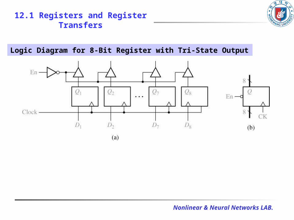
Logic Diagram for 8-Bit Register with Tri-State Output
Nonlinear & Neural Networks LAB.
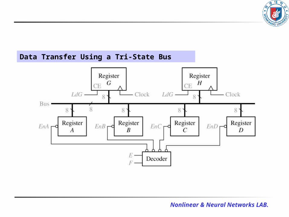
Data Transfer Using a Tri-State Bus

Nonlinear & Neural Networks LAB.
12.1 Registers and Register Transfers
How data can be transferred?
The operation can be summarized as follows:
).or (in stored is ,11 If
).or (in stored is ,10 If
).or (in stored is ,01 If
).or (in stored is ,00 If
HGDEF
HGCEF
HGBEF
HGAEF

Nonlinear & Neural Networks LAB.
12.1 Registers and Register Transfers
Parallel Adder with Accumulator
N-Bit Parallel Adder with Accumulator

Nonlinear & Neural Networks LAB.
12.1 Registers and Register Transfers
Adder Cell with Multiplexer (Figure 12-6)
Nonlinear & Neural Networks LAB.
12-2 Shift Registers
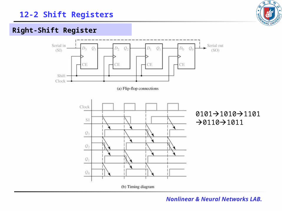
Right-Shift Register
01011010110101101011

Nonlinear & Neural Networks LAB.
12-2 Shift Registers
8-Bit Serial-in, Serial-out Shift Register

Nonlinear & Neural Networks LAB.
12-2 Shift Registers
Typical Timing Diagram for Shift Register

Nonlinear & Neural Networks LAB.
12-2 Shift Registers
Parallel-in, Parallel-Out Right Shift Register

Nonlinear & Neural Networks LAB.
12-2 Shift Registers
Shift Register Operation (Table 12-1)
shiftright Q Q Q SI 1
load Q Q Q Q 1 0
change no Q Q Q Q 0 0
Q Q Q Q (Load) (Shift)
Action StateNext Input
123
0123
0123
0123
LSh

Nonlinear & Neural Networks LAB.
12-2 Shift Registers
Timing Diagram for Shift Register

Nonlinear & Neural Networks LAB.
12-2 Shift Registers
The Next-state equations for the F/F are
10'
0''
0
21'
1''
1
32'
2''
2
3'
3''
3
SI
QShDLShQLShQ
QShDLShQLShQ
QShDLShQLShQ
ShDLShQLShQ

Nonlinear & Neural Networks LAB.
12-2 Shift Registers
Shift Register with Inverted Feedback (Figure 12-12) Johnson Counter
A 3-bit shift register 12-12(a) Successive states 12-12(b)

Nonlinear & Neural Networks LAB.
12.3 Design of Binary Counters
A binary counter using three T F/F to count clock pulses
Synchronous
Binary Counter
(Figure 12-13)
Counting sequence
CBA: 000001010011100101110111000

Nonlinear & Neural Networks LAB.
12.3 Design of Binary Counters
State Table for Binary Counter (Table 12-2)
1 1 1 0 0 0 1 1 1
1 0 0 1 1 1 0 1 1
1 1 0 0 1 1 1 0 1
1 0 0 1 0 1 0 0 1
1 1 1 0 0 1 1 1 0
1 0 0 1 1 0 0 1 0
1 1 0 0 1 0 1 0 0
1 0 0 1 0 0 0 0 0
Inputs Flop-Flip StateNext StatePresent
ABC TTTABCABC
Nonlinear & Neural Networks LAB.
12.3 Design of Binary Counters
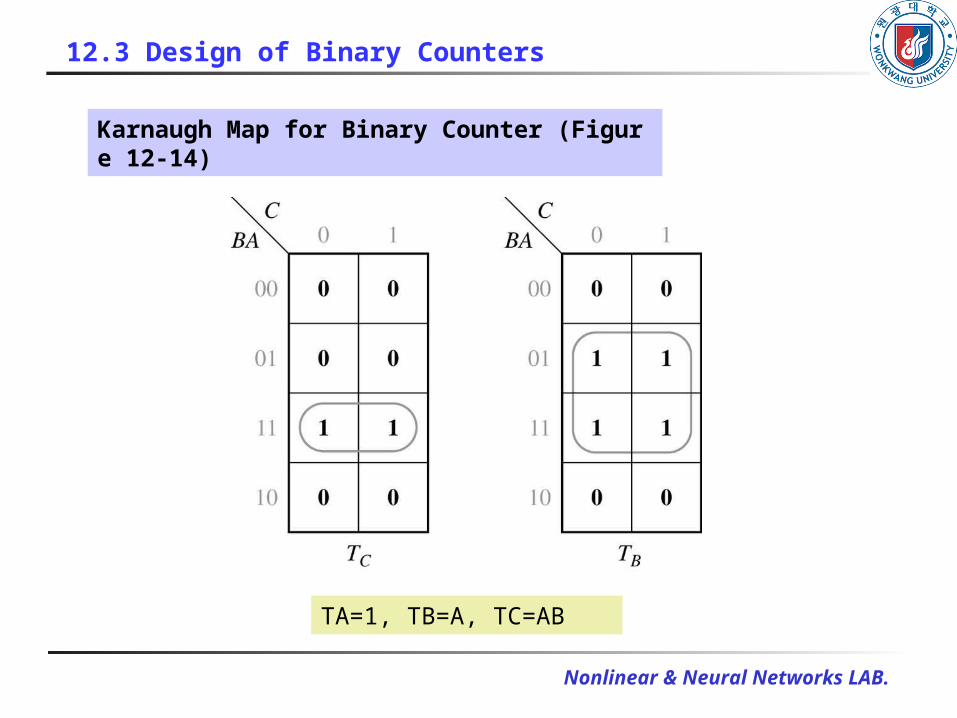
Karnaugh Map for Binary Counter (Figure 12-14)
TA=1, TB=A, TC=AB

Nonlinear & Neural Networks LAB.
12.3 Design of Binary Counters
Binary Counter with D Flip-Flops (Figure 12-15)

Nonlinear & Neural Networks LAB.
12.3 Design of Binary Counters
The D input equations derived from the maps are
BACBACBACCACBBACCD
ABABBABD
AAD
C
B
A
'''''
''
'
)(
Karnaugh Maps for D Flip-Flops (Figure 12-16)
Nonlinear & Neural Networks LAB.
12.3 Design of Binary Counters
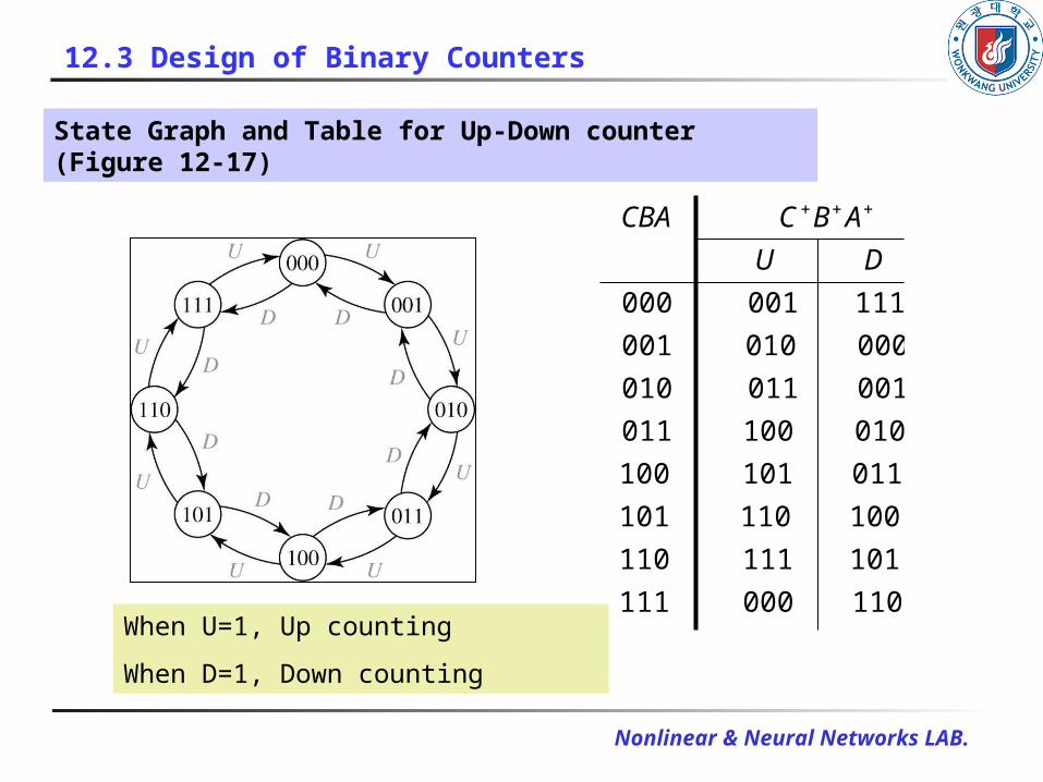
State Graph and Table for Up-Down counter (Figure 12-17)
110 000 111
101 111 110
100 110 101
011 101 100
010 100 011
001 011 010
000 010 001
111 001 000
DU
ABCCBA
When U=1, Up counting
When D=1, Down counting

Nonlinear & Neural Networks LAB.
12.3 Design of Binary Counters
The up-down counter can be implemented using D F/F and gate
Binary Up-Down Counter
(Figure 12-18)

Nonlinear & Neural Networks LAB.
12.3 Design of Binary Counters
The corresponding logic equations are
)(
)(
)(
''
'
ADBUBACCD
DAUABBD
DUAAD
C
B
A
When U=0 and D=1, these equations reduce to
0) when state change (
0) when state change (
cycle)clock every state change ( 1
''
'
'
ABCABCCD
ABABBD
AAAAD
C
B
A

Nonlinear & Neural Networks LAB.
12.3 Design of Binary Counters
Loadable Counter with Count Enable (Figure 12-19)
Loadable counter
(Figure 12-19(a))
Summarizes the counter
operation
(Figure 12-19(b)) 1 statepresent 1 0 1
) ( 0 0 1
)( 1 1
0 0 0 0
N
changenoABC
loadDDD
ABCCtLdClr
ABC
(b)

Nonlinear & Neural Networks LAB.
12.3 Design of Binary Counters
Circuit for Figure 12-19 (Figure 12-20)

Nonlinear & Neural Networks LAB.
12.3 Design of Binary Counters
The next-state equations for the counter of Figure 12-20
ABCtLdDLdCLdDC
ACtLdDLdBLdDB
CtLdDLdALdDA
CinB
BinB
AinA
''
''
''
)(
)(
)(

Nonlinear & Neural Networks LAB.
12.4 Counters for Other Sequences
The sequence of states of a counter is not in straight binary order.
State Graph for Counter
(Figure 12-21)
State Table for Figure 21.21
(Table 12-3)
0 1 0 1 1 1
- - - 0 1 1
- - - 1 0 1
1 1 1 0 0 1
1 1 0 0 1 0
- - - 1 0 0
0 0 1 0 0 0
A B CA B C

Nonlinear & Neural Networks LAB.
12.4 Counters for Other Sequences
The next-state maps in Figure 12-22(a) are easily plotted from inspection of Table 12-3 Use T-F/F
Figure 12-22

Nonlinear & Neural Networks LAB.
12.4 Counters for Other Sequences
Input for T Flip-Flop
(Table 12-4)0 1 1
1 0 1
1 1 0
0 0 0
T Q Q
QQT
Counter Using
T Flip-Flops
(Figure 12-23)

Nonlinear & Neural Networks LAB.
12.4 Counters for Other Sequences
Timing Diagram for Figure 12-23
(Figure 12-24)
State Graph for
Counter
(Figure 12-25)
Nonlinear & Neural Networks LAB.
12.4 Counters for Other Sequences
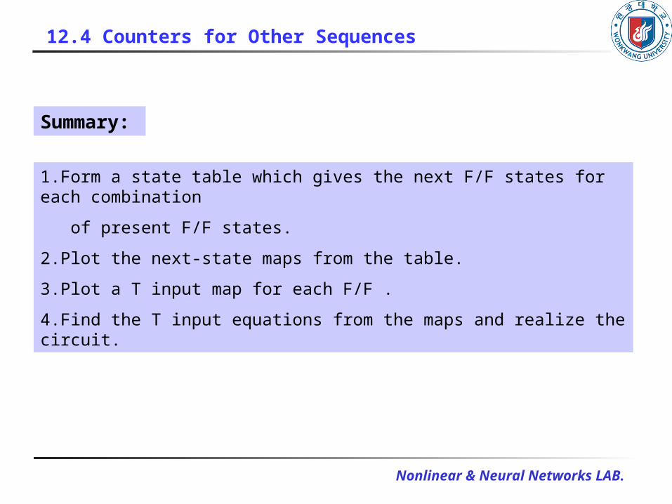
Summary:
1.Form a state table which gives the next F/F states for each combination
of present F/F states.
2.Plot the next-state maps from the table.
3.Plot a T input map for each F/F .
4.Find the T input equations from the maps and realize the circuit.

Nonlinear & Neural Networks LAB.
12.4 Counters for Other Sequences
Counter Design Using D Flip-Flop
Following equations can be read from Figure 12-22(a):
)(
'''
''
BCABACAAD
BACBDBCD
A
BC
Counter of Figure 12-21
Using D Flip-Flops
(Figure 12-26)

Nonlinear & Neural Networks LAB.
12.5 Counter Design Using S-R and J-K Flip-Flops
S-R Flip-Flop Inputs (Table 12-5)
- 1 1 1
- 0 1 1
1 1 0 1
1 0 0 1
0 1 1 0
0 0 1 0
1 1 0 0
0 0 0 0
QQRS
Inputs not allowed
(a)
0 1
0 0 1 1
1 0 0 1
0 1 1 0
1 0
0 0 0 0
SRQQ
(b)
0 1 1
1 0 0 1
0 1 1 0
0 0 0
SRQQ
(c)

Nonlinear & Neural Networks LAB.
12.5 Counter Design Using S-R and J-K Flip-Flops
With columns added for the S and R flip-flop inputs (Table 12-6)
1 0 0 1 0 0 1 0 1 1 1
- - - 0 1 1
- - - 1 0 1
0 1 0 1 0 1 1 1 0 0 1
1 0 1 0 0 0 0 0 1 1 0
0 1 0 0 1 1 0 0 1 0
- - - 1 0 0
0 0 0 1 0 0 1 0 0 0
AABBCC RSRS RSABCABC

Nonlinear & Neural Networks LAB.
12.5 Counter Design Using S-R and J-K Flip-Flops
Counter Design
Using
S-R Flip-Flop

Nonlinear & Neural Networks LAB.
12.5 Counter Design Using S-R and J-K Flip-Flops
0 1 1 1
1 0 1 1
1 1 0 1
1 0 0 1
0 1 1 0
0 0 1 0
1 1 0 0
0 0 0 0
QQKJ
0 1 1
1 0 1
1 1 0
0 0 0
KJQQ
0 1
0 0 1 1
1 1
1 0 0 1
1 1
0 1 1 0
1 0
0 0 0 0
KJQQ
(a) (b) (c)
J-K Flip-Flop Inputs (Table 12-7)

Nonlinear & Neural Networks LAB.
12.5 Counter Design Using S-R and J-K Flip-Flops
1 0 1 0 1 0 1 1 1
- - - 0 1 1
- - - 1 0 1
1 1 0 1 1 1 0 0 1
1 1 0 0 0 0 1 1 0
1 0 0 1 1 0 0 1 0
- - - 1 0 0
0 0 1 0 0 1 0 0 0
AABBCC KJKJ KJABCABC
With columns added for the J and K flip-flop inputs (Table 12-8)

Nonlinear & Neural Networks LAB.
12.6 Derivation of Flip-Flop Input Equations-Summary
Counter of Figure 12-21
Using J-K Flip-Flops
(Figure 12-28)
Nonlinear & Neural Networks LAB.
12.6 Derivation of Flip-Flop Input Equations-Summary
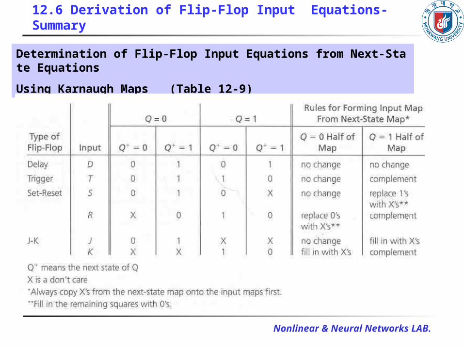
Determination of Flip-Flop Input Equations from Next-State Equations
Using Karnaugh Maps (Table 12-9)

Nonlinear & Neural Networks LAB.
12.6 Derivation of Flip-Flop Input Equations-Summary
Example (illustrating the use of Table 12-9)

Nonlinear & Neural Networks LAB.
12.6 Derivation of Flip-Flop Input Equations-Summary
Derivation of
Flip-Flop Input
Equations Using
4-Variable Maps
(Figure 12-29)