13-counters and registers 1
TRANSCRIPT

7/31/2019 13-Counters and Registers 1
http://slidepdf.com/reader/full/13-counters-and-registers-1 1/17
SEE1223: Digital Electronics6 – Counters and Registers
Zulkifil Md Yusof
Dept. of Microelectronics and Computer Engineering
The Faculty of Electrical Engineering
Universiti Teknologi Malaysia
7/31/2019 13-Counters and Registers 1
http://slidepdf.com/reader/full/13-counters-and-registers-1 2/17
Counter and Registers
• Counters – Asynchronous Counters
– Synchronous Counters
– Design of Synchronous Counters
– 74163 devices
• Registers
– Shift Registers
• SISO, SIPO, PISO, PIPO
– Shift Register Counters
• Johnson and Ring
– 74164, 74165, 74194, and 74195 devices
2/18/2012 A.A.H Ab-Rahman, Z.Md-Yusof 2
7/31/2019 13-Counters and Registers 1
http://slidepdf.com/reader/full/13-counters-and-registers-1 3/17
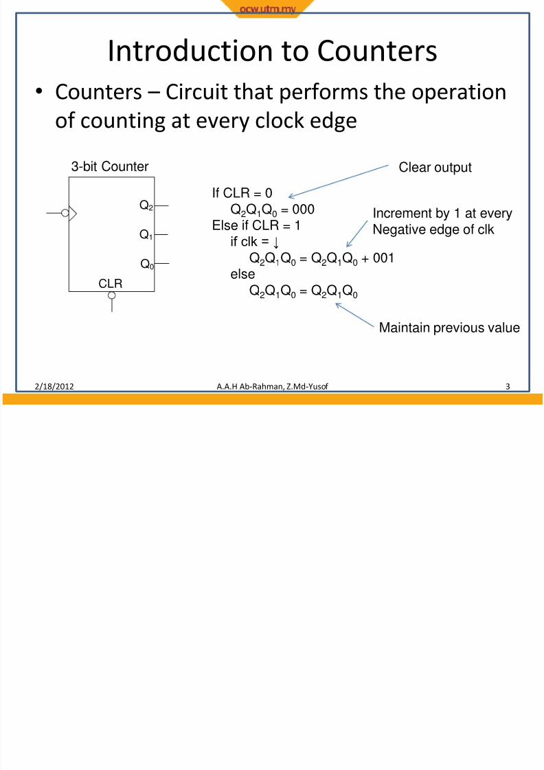
Introduction to Counters
• Counters –
Circuit that performs the operationof counting at every clock edge
2/18/2012 A.A.H Ab-Rahman, Z.Md-Yusof 3
If CLR = 0Q2Q1Q0 = 000
Else if CLR = 1if clk = ↓
Q2Q1Q0 = Q2Q1Q0 + 001else
Q2Q1Q0 = Q2Q1Q0 CLR
Q2
Q1
Q0
3-bit Counter Clear output
Increment by 1 at everyNegative edge of clk
Maintain previous value
7/31/2019 13-Counters and Registers 1
http://slidepdf.com/reader/full/13-counters-and-registers-1 4/17
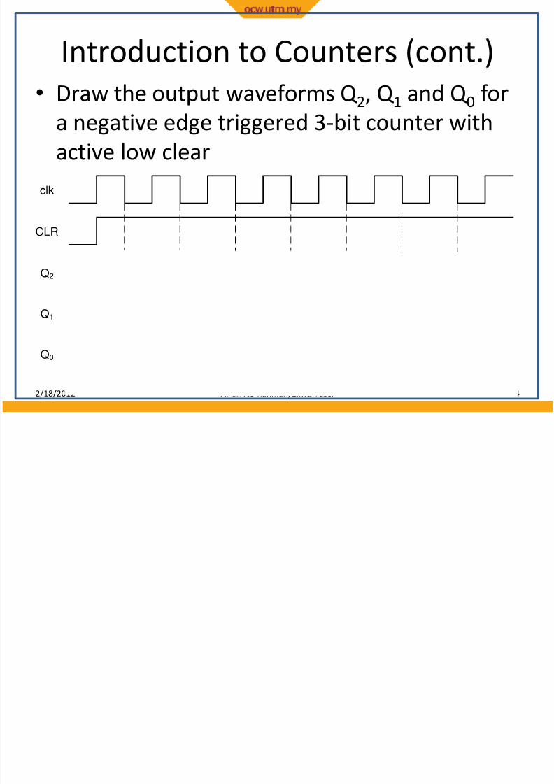
Introduction to Counters (cont.)
• Draw the output waveforms Q 2, Q 1 and Q 0 fora negative edge triggered 3-bit counter with
active low clear
2/18/2012 A.A.H Ab-Rahman, Z.Md-Yusof 4
clk
CLR
Q2
Q1
Q0
7/31/2019 13-Counters and Registers 1
http://slidepdf.com/reader/full/13-counters-and-registers-1 5/17
Introduction to Counters (cont.)
• Counter are designed using flip-flops, typicallythe negative edge triggered
• Counters can be designed as asynchronous orsynchronous
• Asynchronous counters –
The clock is applied onthe first stage. Subsequent stages derive the clockfrom the previous stage
• Synchronous counters – The clock is applied to all
stages using a common clock signal• Synchronous counters perform better than
asynchronous counters, therefore, are widelyused in digital systems
2/18/2012 A.A.H Ab-Rahman, Z.Md-Yusof 5
7/31/2019 13-Counters and Registers 1
http://slidepdf.com/reader/full/13-counters-and-registers-1 6/17
T Q
Q
CLR
T Q
Q
CLR
T Q
Q
CLR
clk
1 1 1
CLR
Q2Q1Q0
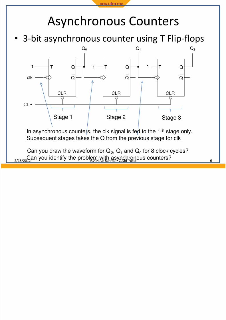
Asynchronous Counters
• 3-bit asynchronous counter using T Flip-flops
2/18/2012 A.A.H Ab-Rahman, Z.Md-Yusof 6
Stage 1 Stage 2 Stage 3
In asynchronous counters, the clk signal is fed to the 1st stage only.Subsequent stages takes the Q from the previous stage for clk
Can you draw the waveform for Q2, Q1 and Q0 for 8 clock cycles?
Can you identify the problem with asynchronous counters?
7/31/2019 13-Counters and Registers 1
http://slidepdf.com/reader/full/13-counters-and-registers-1 7/17
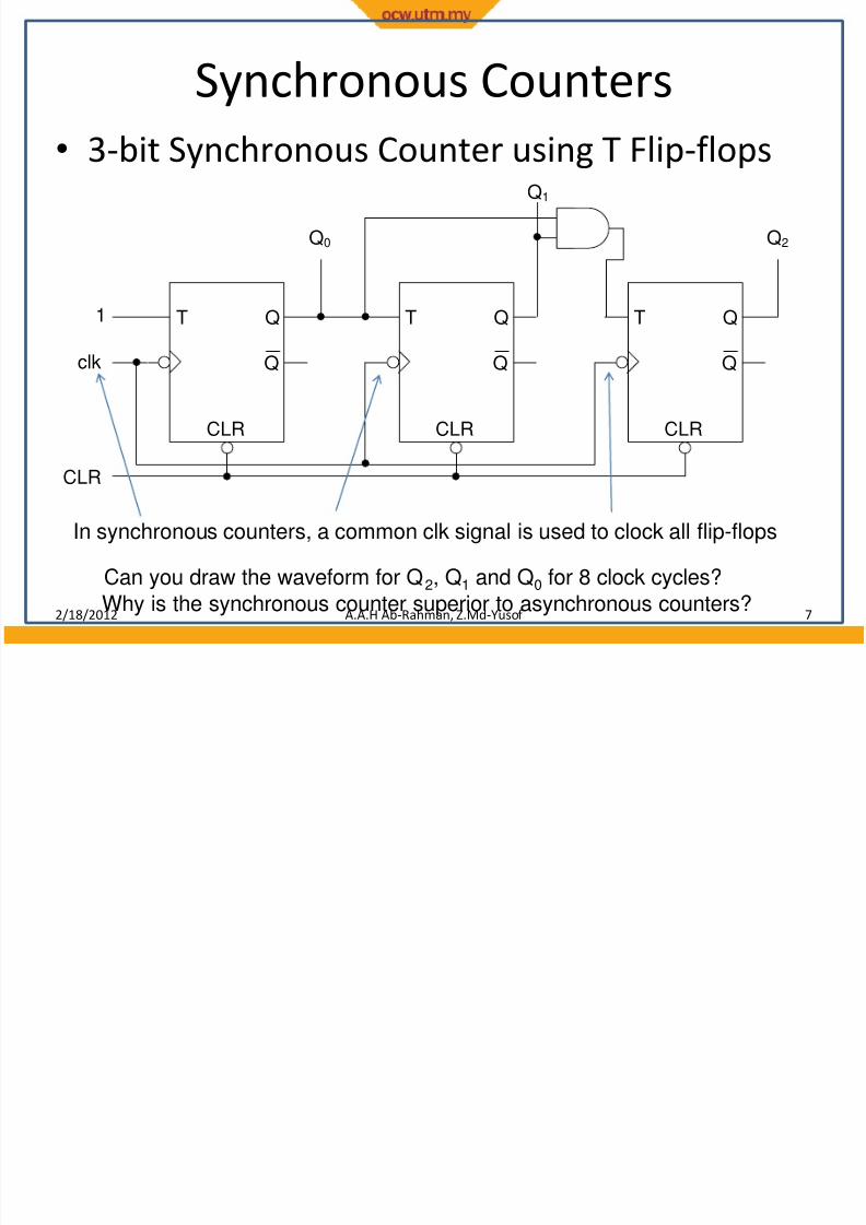
Synchronous Counters
• 3-bit Synchronous Counter using T Flip-flops
2/18/2012 A.A.H Ab-Rahman, Z.Md-Yusof 7
T Q
Q
CLR
T Q
Q
CLR
T Q
Q
CLR
clk
1
CLR
Q2
Q1
Q0
In synchronous counters, a common clk signal is used to clock all flip-flops
Can you draw the waveform for Q2, Q1 and Q0 for 8 clock cycles?
Why is the synchronous counter superior to asynchronous counters?
7/31/2019 13-Counters and Registers 1
http://slidepdf.com/reader/full/13-counters-and-registers-1 8/17
Design of Synchronous Counters
• How to design the 3-bit synchronous counter? – There is a systematic procedure of designing
synchronous counters
• Step 1: Derive the state transition diagram
• Step 2: Derive the next state and state transition table
• Step 3: Using K-Maps, derive the logic expressions
• Step 4: Implement the circuit
2/18/2012 A.A.H Ab-Rahman, Z.Md-Yusof 8
7/31/2019 13-Counters and Registers 1
http://slidepdf.com/reader/full/13-counters-and-registers-1 9/17
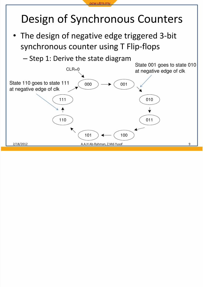
Design of Synchronous Counters
• The design of negative edge triggered 3-bitsynchronous counter using T Flip-flops
– Step 1: Derive the state diagram
2/18/2012 A.A.H Ab-Rahman, Z.Md-Yusof 9
000 001
010
011
101 100
111
110
CLR=0State 001 goes to state 010
at negative edge of clk
State 110 goes to state 111at negative edge of clk
7/31/2019 13-Counters and Registers 1
http://slidepdf.com/reader/full/13-counters-and-registers-1 10/17
Design of Synchronous Counters
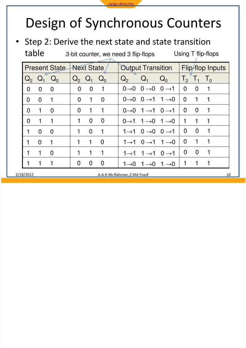
• Step 2: Derive the next state and state transitiontable
2/18/2012 A.A.H Ab-Rahman, Z.Md-Yusof 10
Present State Next State Output Transition Flip-flop Inputs
Q2 Q1 Q0 Q2 Q1 Q0 Q2 Q1 Q0 T2 T1 T0
0 0 0
3-bit counter, we need 3 flip-flops Using T flip-flops
0 0 1 0→0 0 →0 0 →1 0 0 1
0 0 1 0 1 0 0→0 0 →1 1 →0 0 1 1
0 1 0
0 1 1
1 0 0
1 0 1
1 1 0
1 1 1
0 1 1
1 0 0
1 0 1
1 1 0
1 1 1
0 0 0
0→0 1 →1 0 →1
0→1 1 →0 1 →0
1→1 0 →0 0 →1
1→1 0 →1 1 →0
1→1 1 →1 0 →1
1→0 1 →0 1 →0
0 0 1
1 1 1
0 0 1
0 1 1
0 0 1
1 1 1
7/31/2019 13-Counters and Registers 1
http://slidepdf.com/reader/full/13-counters-and-registers-1 11/17
Design of Synchronous Counters
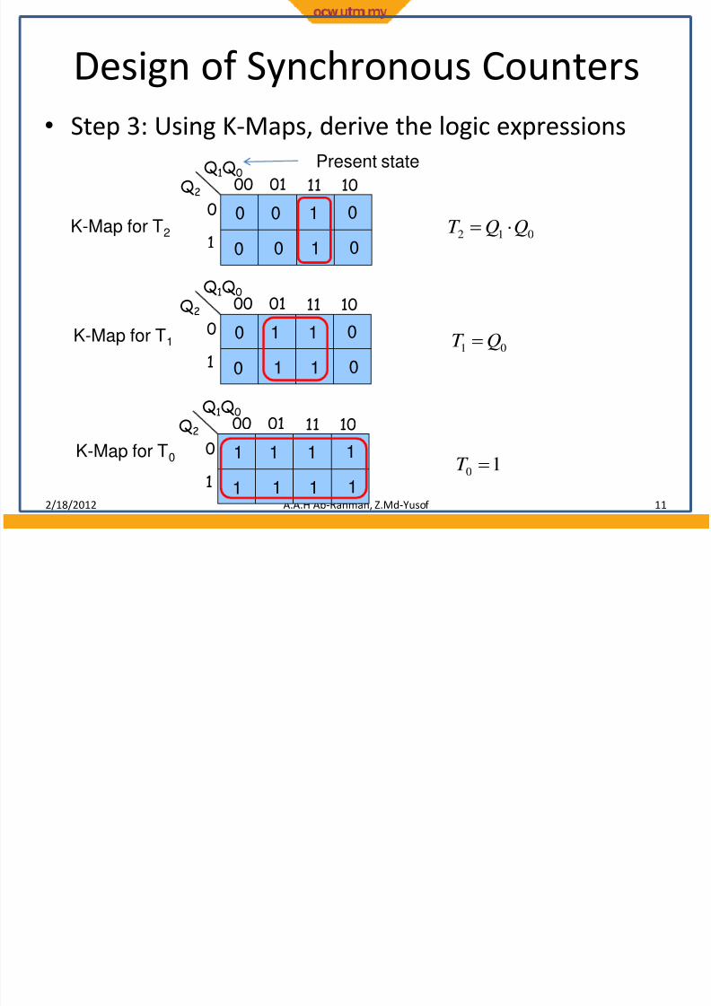
• Step 3: Using K-Maps, derive the logic expressions
2/18/2012 A.A.H Ab-Rahman, Z.Md-Yusof 11
00 01Q1Q0
Q2
0
1
11 10
0 0 1
0 0 1
0
0
K-Map for T2
K-Map for T1
K-Map for T0
00 01Q1Q0
Q2
0
1
11 10
0 1 1
0 1 1
0
0
00 01Q1Q0
Q2
0
1
11 10
1 1 1
1 1 1
1
1
012QQT
01QT
10T
Present state

7/31/2019 13-Counters and Registers 1
http://slidepdf.com/reader/full/13-counters-and-registers-1 12/17
Design of Synchronous Counters
• Step 4: Implement the circuit
2/18/2012 A.A.H Ab-Rahman, Z.Md-Yusof 12
T Q
Q
CLR
T Q
Q
CLR
T Q
Q
CLR
clk
1
CLR
Q2
Q1
Q0
012QQT
01QT 1
0T
Which is the same circuit as before
7/31/2019 13-Counters and Registers 1
http://slidepdf.com/reader/full/13-counters-and-registers-1 13/17
Design of Synchronous Counters
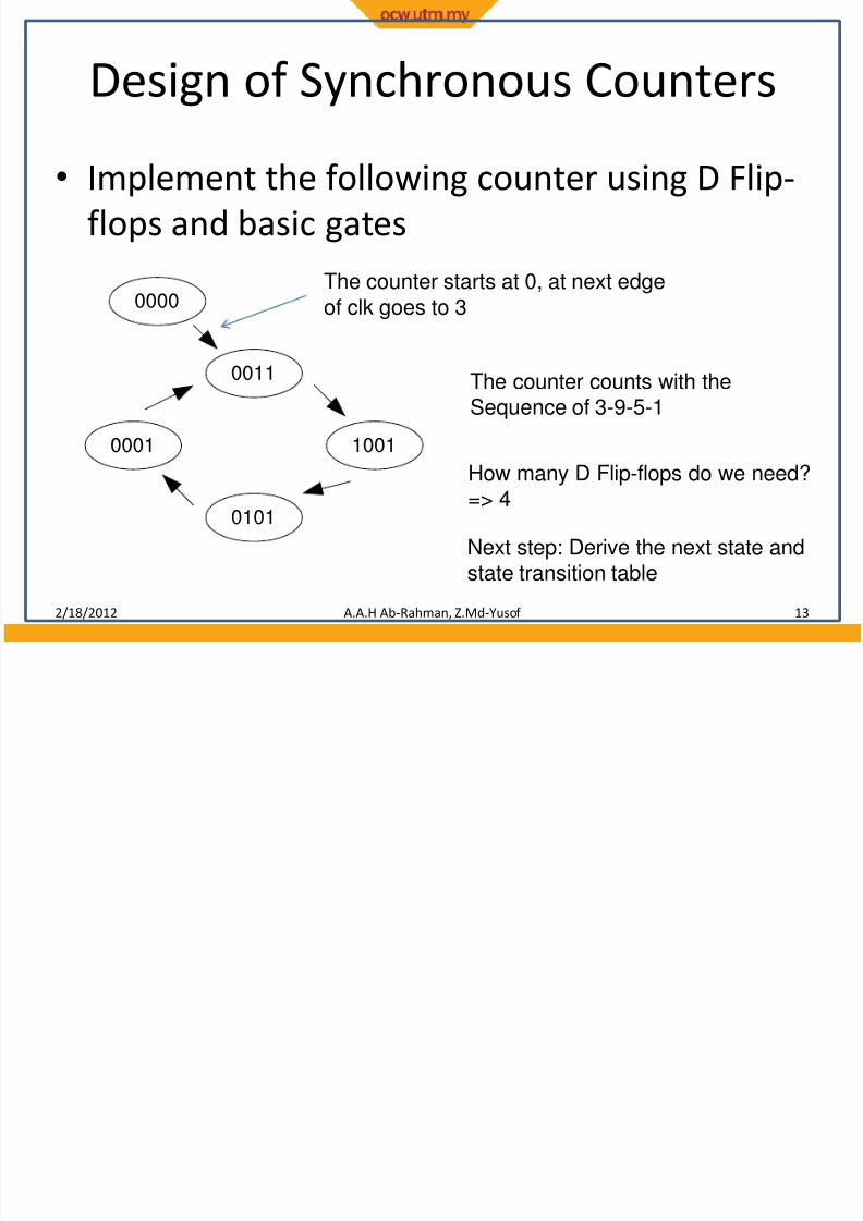
• Implement the following counter using D Flip-
flops and basic gates
2/18/2012 A.A.H Ab-Rahman, Z.Md-Yusof 13
0011
1001
0101
0001
0000
The counter starts at 0, at next edge
of clk goes to 3
The counter counts with theSequence of 3-9-5-1
How many D Flip-flops do we need?=> 4
Next step: Derive the next state andstate transition table
7/31/2019 13-Counters and Registers 1
http://slidepdf.com/reader/full/13-counters-and-registers-1 14/17
Design of Synchronous Counters
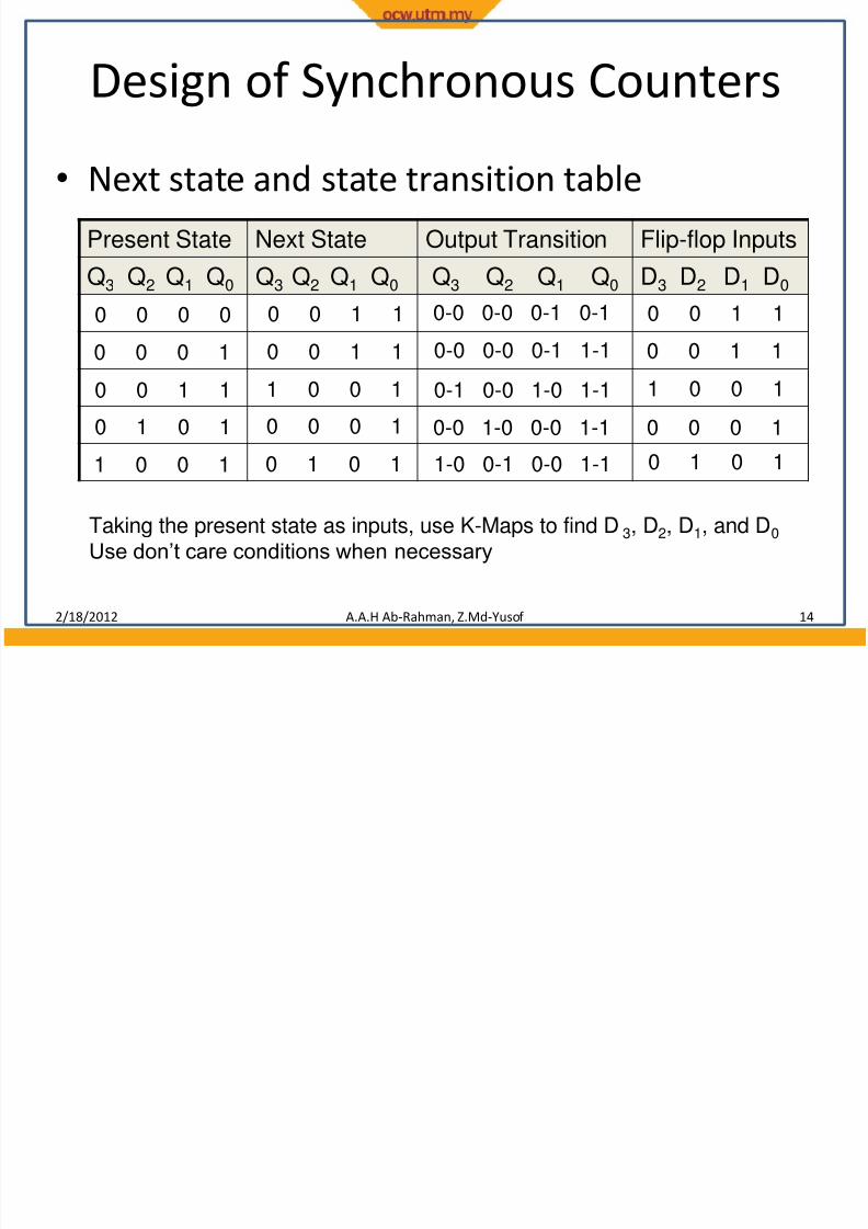
• Next state and state transition table
2/18/2012 A.A.H Ab-Rahman, Z.Md-Yusof 14
Present State Next State Output Transition Flip-flop Inputs
Q3 Q2 Q1 Q0 Q3 Q2 Q1 Q0 Q3 Q2 Q1 Q0 D3 D2 D1 D0
0 0 0 0 0 0 1 1 0-0 0-0 0-1 0-1 0 0 1 1
0 0 0 1 0 0 1 1 0-0 0-0 0-1 1-1 0 0 1 1
0 0 1 1
0 1 0 1
1 0 0 1
1 0 0 1
0 0 0 1
0 1 0 1
0-1 0-0 1-0 1-1
0-0 1-0 0-0 1-1
1-0 0-1 0-0 1-1
1 0 0 1
0 0 0 1
0 1 0 1
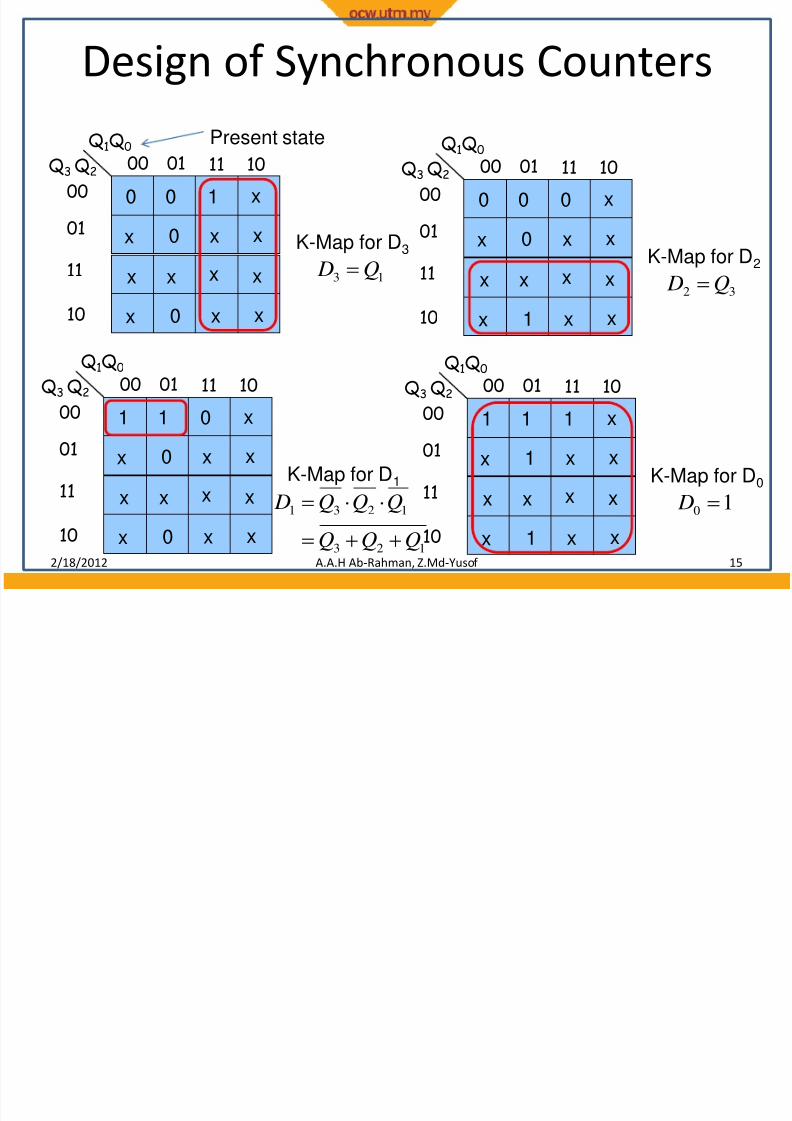
Taking the present state as inputs, use K-Maps to find D3, D2, D1, and D0
Use don’t care conditions when necessary
7/31/2019 13-Counters and Registers 1
http://slidepdf.com/reader/full/13-counters-and-registers-1 15/17
Design of Synchronous Counters
2/18/2012 A.A.H Ab-Rahman, Z.Md-Yusof 15
00 01
00
01
11 10
11
10
0 0 1
x 0 x
x
x
x x x
x 0 x
x
x
Q1Q0
Q3 Q2
K-Map for D3
13 Q D
Present state00 01
00
01
11 10
11
10
0 0 0
x 0 x
x
x
x x x
x 1 x
x
x
Q1Q0
Q3 Q2
K-Map for D2
32 Q D
00 01
00
01
11 10
11
10
1 1 0
x 0 x
x
x
x x x
x 0 x
x
x
Q1Q0
Q3 Q2
K-Map for D1
123
1231
QQQ
QQQ D
00 01
00
01
11 10
11
10
1 1 1
x 1 x
x
x
x x x
x 1 x
x
x
Q1Q0
Q3 Q2
K-Map for D0
10 D
7/31/2019 13-Counters and Registers 1
http://slidepdf.com/reader/full/13-counters-and-registers-1 16/17
D Q
Q
CLR
D Q
Q
CLR
D Q
Q
CLR
D Q
Q
CLR
clk
CLR
Q2Q1Q0 Q3
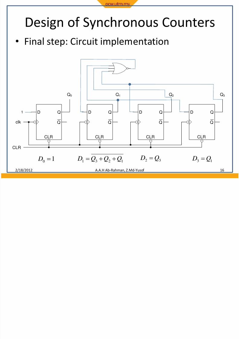
Design of Synchronous Counters
• Final step: Circuit implementation
2/18/2012 A.A.H Ab-Rahman, Z.Md-Yusof 16
1
13Q D 32
Q D 1231
QQQ D 10 D
7/31/2019 13-Counters and Registers 1
http://slidepdf.com/reader/full/13-counters-and-registers-1 17/17
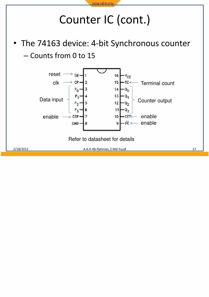
Counter IC (cont.)
• The 74163 device: 4-bit Synchronous counter
– Counts from 0 to 15
2/18/2012 A.A.H Ab-Rahman, Z.Md-Yusof 17
reset
clk
Data input Counter output
Terminal count
enable
enableenable
Refer to datasheet for details