an aerodynamic study of bicycle wheel performance using cfd · an aerodynamic study of bicycle...
TRANSCRIPT
STAR European Conference © 2010 Intelligent Light
An Aerodynamic Study of Bicycle
Wheel Performance using CFD
Matthew N. Godo, Ph.D.FieldView Product Manager
STAR European Conference © 2010 Intelligent Light
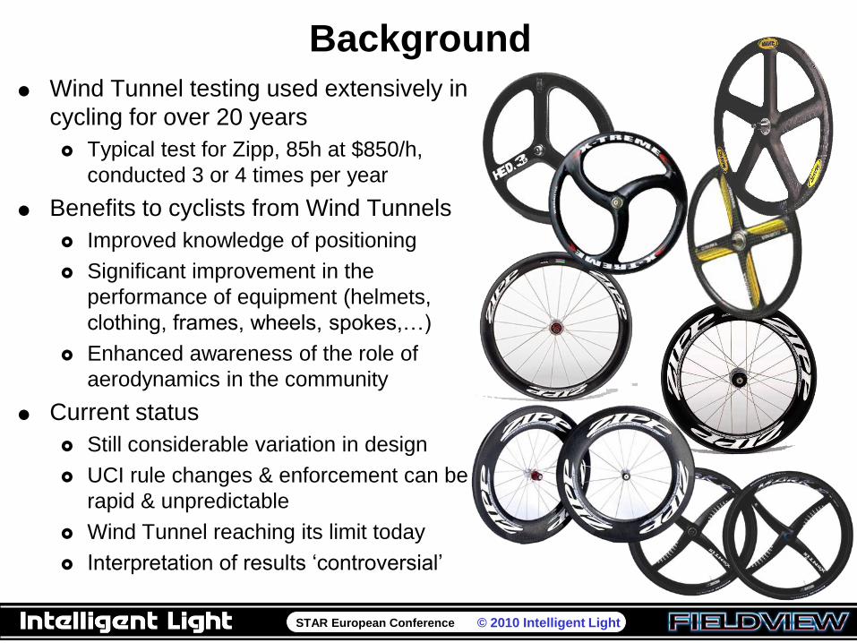
Background
Wind Tunnel testing used extensively in
cycling for over 20 years
Typical test for Zipp, 85h at $850/h,
conducted 3 or 4 times per year
Benefits to cyclists from Wind Tunnels
Improved knowledge of positioning
Significant improvement in the
performance of equipment (helmets,
clothing, frames, wheels, spokes,…)
Enhanced awareness of the role of
aerodynamics in the community
Current status
Still considerable variation in design
UCI rule changes & enforcement can be
rapid & unpredictable
Wind Tunnel reaching its limit today
Interpretation of results „controversial‟
Advertisement ca 2007
STAR European Conference © 2010 Intelligent Light
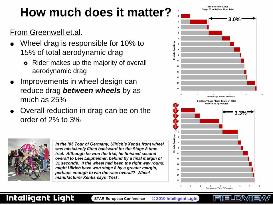
How much does it matter?
From Greenwell et.al.
Wheel drag is responsible for 10% to
15% of total aerodynamic drag
Rider makes up the majority of overall
aerodynamic drag
Improvements in wheel design can
reduce drag between wheels by as
much as 25%
Overall reduction in drag can be on the
order of 2% to 3%
0 1 2 3 4 5
Percentage Time Difference
15
14
13
12
11
10
9
8
7
6
5
4
3
2
1
Fin
ish
Po
sit
ion
Tour de France 2008
Stage 20 Individual Time Trial
3.0%
0 1 2 3 4 5 6 7 8
Percentage Time Difference
15
14
13
12
11
10
9
8
7
6
5
4
3
2
1
Fin
ish
Po
sit
ion
IronManTM Lake Placid Triathlon 2008
Male 45-49 Age Group
3.3%
QQQQQ
In the ‟05 Tour of Germany, Ullrich‟s Xentis front wheel was mistakenly fitted backward for the Stage 8 time trial. Although he won the trial, he finished second overall to Levi Leipheimer, behind by a final margin of 31 seconds. If the wheel had been the right way round, might Ullrich have won stage 8 by a greater margin, perhaps enough to win the race overall? Wheel manufacturer Xentis says „Yes!‟.
STAR European Conference © 2010 Intelligent Light
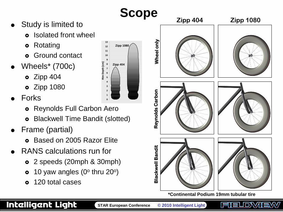
Scope Study is limited to
Isolated front wheel
Rotating
Ground contact
Wheels* (700c)
Zipp 404
Zipp 1080
Forks
Reynolds Full Carbon Aero
Blackwell Time Bandit (slotted)
Frame (partial)
Based on 2005 Razor Elite
RANS calculations run for
2 speeds (20mph & 30mph)
10 yaw angles (0o thru 20o)
120 total cases
Zipp 404 Zipp 1080
Wh
ee
l o
nly
Re
yn
old
s C
arb
on
Bla
ck
we
ll B
an
dit
*Continental Podium 19mm tubular tire
0
1
2
3
4
5
6
7
8
9
10
11
12
13
Rim
Dep
th [
cm
]
Zipp 404
Zipp 1080
STAR European Conference © 2010 Intelligent Light
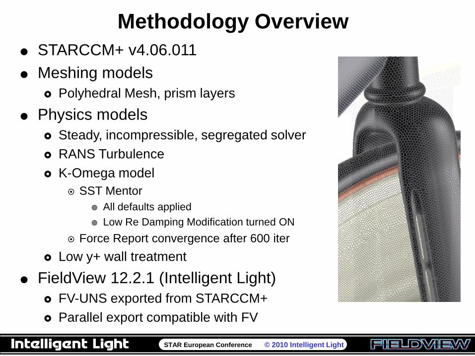
Methodology Overview
STARCCM+ v4.06.011
Meshing models
Polyhedral Mesh, prism layers
Physics models
Steady, incompressible, segregated solver
RANS Turbulence
K-Omega model
SST Mentor
All defaults applied
Low Re Damping Modification turned ON
Force Report convergence after 600 iter
Low y+ wall treatment
FieldView 12.2.1 (Intelligent Light)
FV-UNS exported from STARCCM+
Parallel export compatible with FV
STAR European Conference © 2010 Intelligent Light
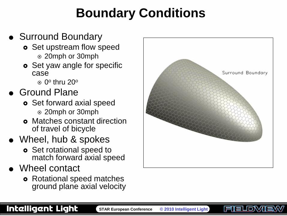
Boundary Conditions
Surround Boundary Set upstream flow speed
20mph or 30mph
Set yaw angle for specific case 0o thru 20o
Ground Plane Set forward axial speed
20mph or 30mph
Matches constant direction of travel of bicycle
Wheel, hub & spokes Set rotational speed to
match forward axial speed
Wheel contact Rotational speed matches
ground plane axial velocity
STAR European Conference © 2010 Intelligent Light
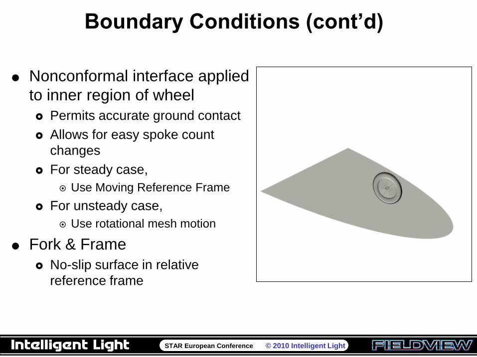
Boundary Conditions (cont’d)
Nonconformal interface applied
to inner region of wheel
Permits accurate ground contact
Allows for easy spoke count
changes
For steady case,
Use Moving Reference Frame
For unsteady case,
Use rotational mesh motion
Fork & Frame
No-slip surface in relative
reference frame
STAR European Conference © 2010 Intelligent Light
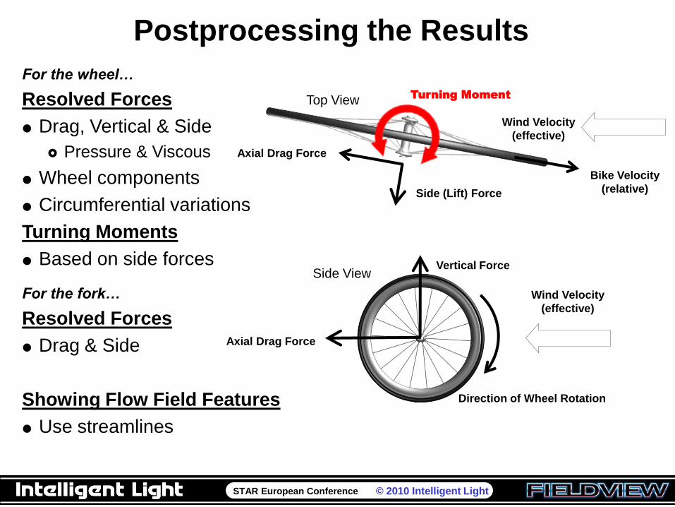
Postprocessing the Results
Side View
Axial Drag Force
Vertical Force
Direction of Wheel Rotation
Wind Velocity
(effective)
Top View
Axial Drag Force
Side (Lift) Force
Bike Velocity
(relative)
Wind Velocity
(effective)
Turning Moment
For the wheel…
Resolved Forces
Drag, Vertical & Side
Pressure & Viscous
Wheel components
Circumferential variations
Turning Moments
Based on side forces
For the fork…
Resolved Forces
Drag & Side
Showing Flow Field Features
Use streamlines
STAR European Conference © 2010 Intelligent Light
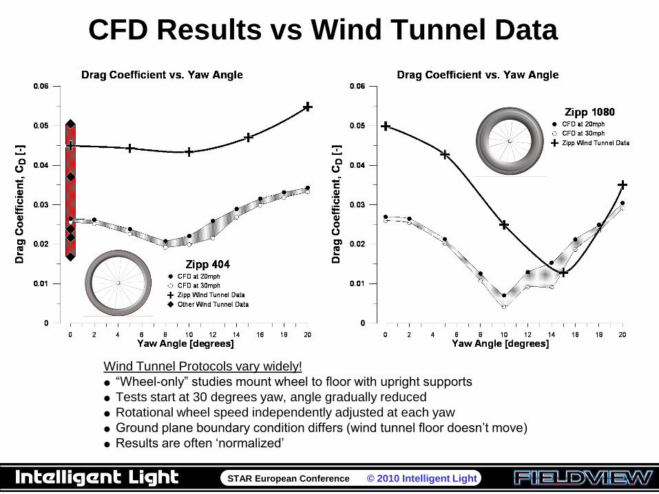
CFD Results vs Wind Tunnel Data
Wind Tunnel Protocols vary widely!
“Wheel-only” studies mount wheel to floor with upright supports
Tests start at 30 degrees yaw, angle gradually reduced
Rotational wheel speed independently adjusted at each yaw
Ground plane boundary condition differs (wind tunnel floor doesn‟t move)
Results are often „normalized‟
STAR European Conference © 2010 Intelligent Light
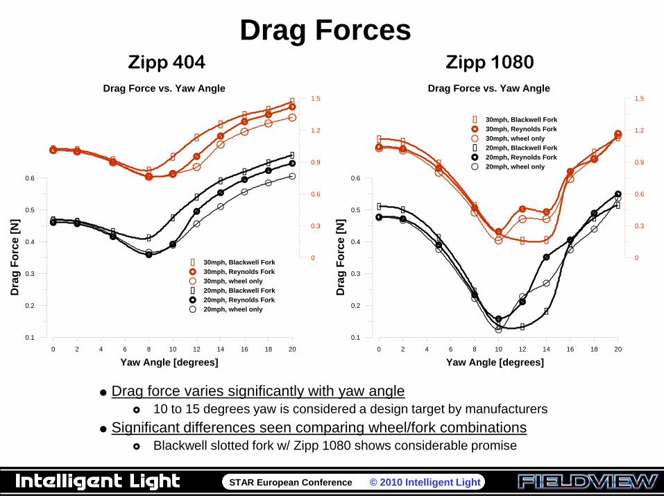
Drag ForcesZipp 404 Zipp 1080
Drag force varies significantly with yaw angle
10 to 15 degrees yaw is considered a design target by manufacturers
Significant differences seen comparing wheel/fork combinations
Blackwell slotted fork w/ Zipp 1080 shows considerable promise
0 2 4 6 8 10 12 14 16 18 20
Yaw Angle [degrees]
0.1
0.2
0.3
0.4
0.5
0.6
Dra
g F
orc
e [
N]
0
0.3
0.6
0.9
1.2
1.5
30mph, Blackwell Fork
30mph, Reynolds Fork
30mph, wheel only
20mph, Blackwell Fork
20mph, Reynolds Fork
20mph, wheel only
Drag Force vs. Yaw Angle
0 2 4 6 8 10 12 14 16 18 20
Yaw Angle [degrees]
0.1
0.2
0.3
0.4
0.5
0.6
Dra
g F
orc
e [
N]
0
0.3
0.6
0.9
1.2
1.5
30mph, Blackwell Fork
30mph, Reynolds Fork
30mph, wheel only
20mph, Blackwell Fork
20mph, Reynolds Fork
20mph, wheel only
Drag Force vs. Yaw Angle
STAR European Conference © 2010 Intelligent Light
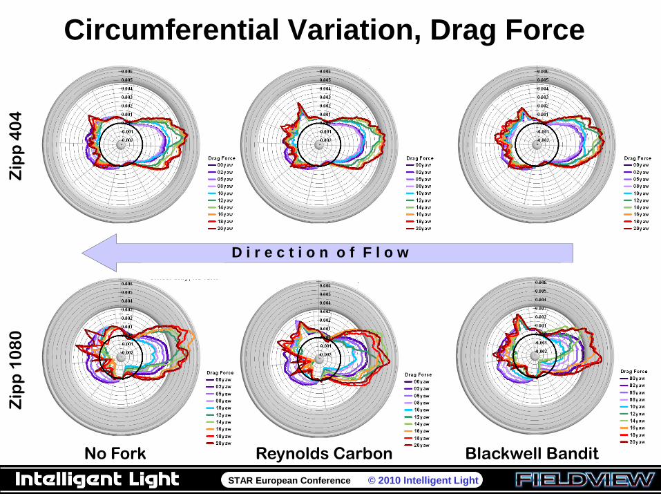
Circumferential Variation, Drag Force
D i r e c t i o n o f F l o w
Zip
p 4
04
Zip
p 1
08
0
No Fork Reynolds Carbon Blackwell Bandit
STAR European Conference © 2010 Intelligent Light
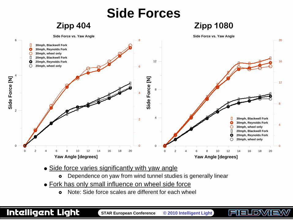
Side Forces
0 2 4 6 8 10 12 14 16 18 20
Yaw Angle [degrees]
0
2
4
6
Sid
e F
orc
e [
N]
0
2
4
6
8
30mph, Blackwell Fork
30mph, Reynolds Fork
30mph, wheel only
20mph, Blackwell Fork
20mph, Reynolds Fork
20mph, wheel only
Side Force vs. Yaw Angle
0 2 4 6 8 10 12 14 16 18 20
Yaw Angle [degrees]
0
4
8
12
Sid
e F
orc
e [
N]
0
4
8
12
16
20
30mph, Blackwell Fork
30mph, Reynolds Fork
30mph, wheel only
20mph, Blackwell Fork
20mph, Reynolds Fork
20mph, wheel only
Side Force vs. Yaw Angle
Zipp 404 Zipp 1080
Side force varies significantly with yaw angle
Dependence on yaw from wind tunnel studies is generally linear
Fork has only small influence on wheel side force
Note: Side force scales are different for each wheel
STAR European Conference © 2010 Intelligent Light
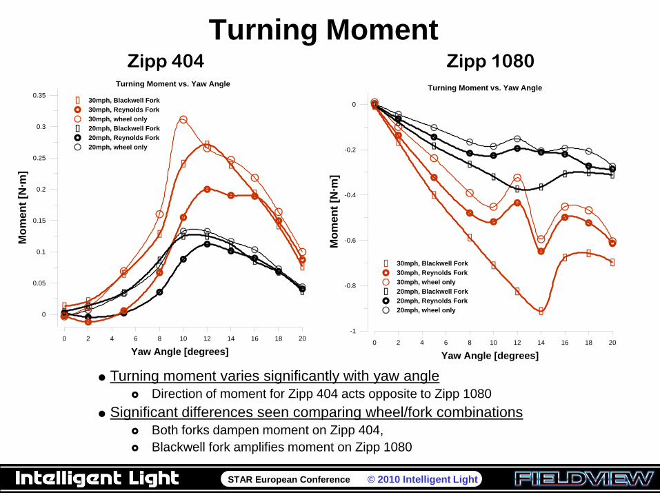
Turning Moment
0 2 4 6 8 10 12 14 16 18 20
Yaw Angle [degrees]
0
0.05
0.1
0.15
0.2
0.25
0.3
0.35
Mo
men
t [N
·m]
30mph, Blackwell Fork
30mph, Reynolds Fork
30mph, wheel only
20mph, Blackwell Fork
20mph, Reynolds Fork
20mph, wheel only
Turning Moment vs. Yaw Angle
0 2 4 6 8 10 12 14 16 18 20
Yaw Angle [degrees]
-1
-0.8
-0.6
-0.4
-0.2
0
Mo
men
t [N
·m]
30mph, Blackwell Fork
30mph, Reynolds Fork
30mph, wheel only
20mph, Blackwell Fork
20mph, Reynolds Fork
20mph, wheel only
Turning Moment vs. Yaw Angle
Zipp 404 Zipp 1080
Turning moment varies significantly with yaw angle
Direction of moment for Zipp 404 acts opposite to Zipp 1080
Significant differences seen comparing wheel/fork combinations
Both forks dampen moment on Zipp 404,
Blackwell fork amplifies moment on Zipp 1080
STAR European Conference © 2010 Intelligent Light
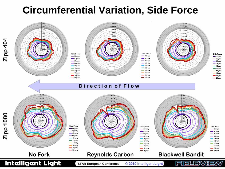
Circumferential Variation, Side ForceZ
ipp
40
4Z
ipp
10
80
No Fork Reynolds Carbon Blackwell Bandit
D i r e c t i o n o f F l o w
STAR European Conference © 2010 Intelligent Light
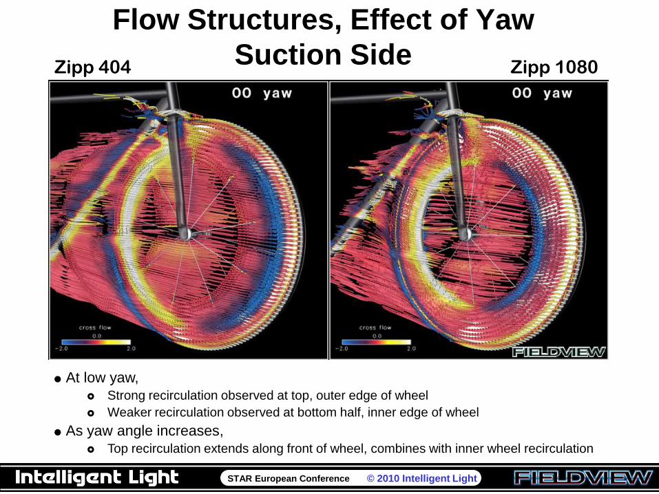
Flow Structures, Effect of Yaw
Suction SideZipp 404 Zipp 1080
At low yaw,
Strong recirculation observed at top, outer edge of wheel
Weaker recirculation observed at bottom half, inner edge of wheel
As yaw angle increases,
Top recirculation extends along front of wheel, combines with inner wheel recirculation
STAR European Conference © 2010 Intelligent Light
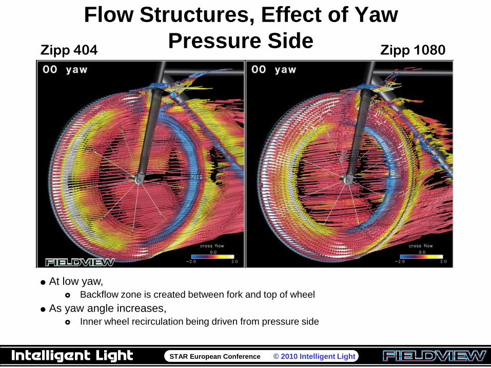
Flow Structures, Effect of Yaw
Pressure SideZipp 404 Zipp 1080
At low yaw,
Backflow zone is created between fork and top of wheel
As yaw angle increases,
Inner wheel recirculation being driven from pressure side
STAR European Conference © 2010 Intelligent Light
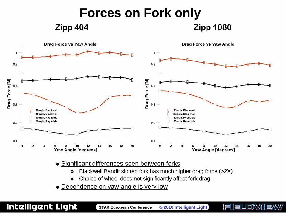
Forces on Fork only
0 2 4 6 8 10 12 14 16 18 20
Yaw Angle [degrees]
0.1
0.2
0.3
0.4
0.9
1
Dra
g F
orc
e [
N]
30mph, Blackwell
20mph, Blackwell
30mph, Reynolds
20mph, Reynolds
Drag Force vs Yaw Angle
0 2 4 6 8 10 12 14 16 18 20
Yaw Angle [degrees]
0.1
0.2
0.3
0.4
0.9
1
Dra
g F
orc
e [
N]
30mph, Blackwell
20mph, Blackwell
30mph, Reynolds
20mph, Reynolds
Drag Force vs Yaw Angle
Zipp 404 Zipp 1080
Significant differences seen between forks
Blackwell Bandit slotted fork has much higher drag force (>2X)
Choice of wheel does not significantly affect fork drag
Dependence on yaw angle is very low
STAR European Conference © 2010 Intelligent Light
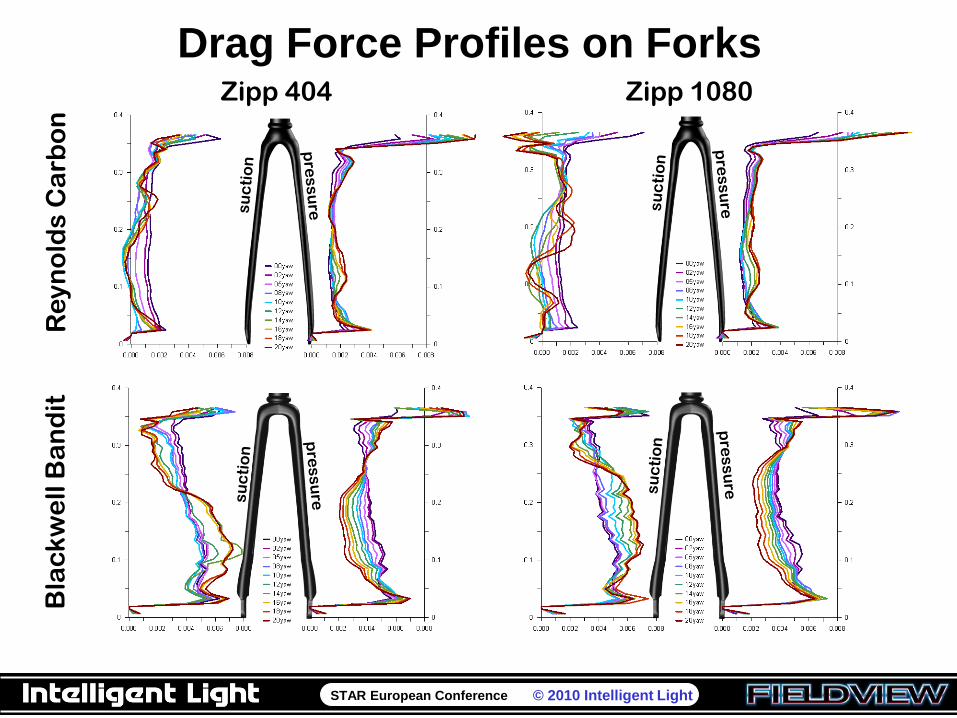
Drag Force Profiles on ForksZipp 404 Zipp 1080
Re
yn
old
s C
arb
on
Bla
ck
we
ll B
an
dit
STAR European Conference © 2010 Intelligent Light
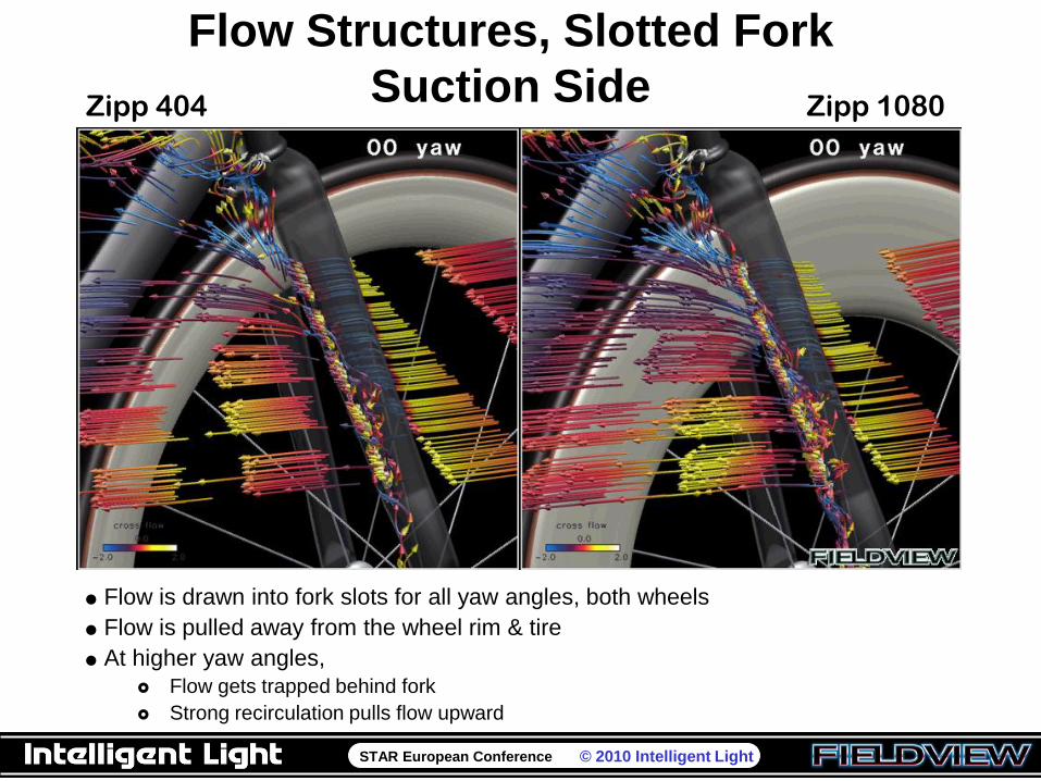
Flow Structures, Slotted Fork
Suction SideZipp 404 Zipp 1080
Flow is drawn into fork slots for all yaw angles, both wheels
Flow is pulled away from the wheel rim & tire
At higher yaw angles,
Flow gets trapped behind fork
Strong recirculation pulls flow upward
STAR European Conference © 2010 Intelligent Light
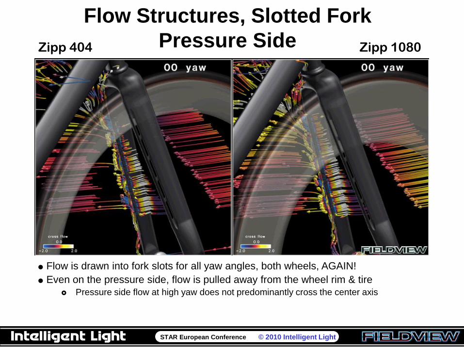
Flow Structures, Slotted Fork
Pressure SideZipp 404 Zipp 1080
Flow is drawn into fork slots for all yaw angles, both wheels, AGAIN!
Even on the pressure side, flow is pulled away from the wheel rim & tire
Pressure side flow at high yaw does not predominantly cross the center axis
STAR European Conference © 2010 Intelligent Light
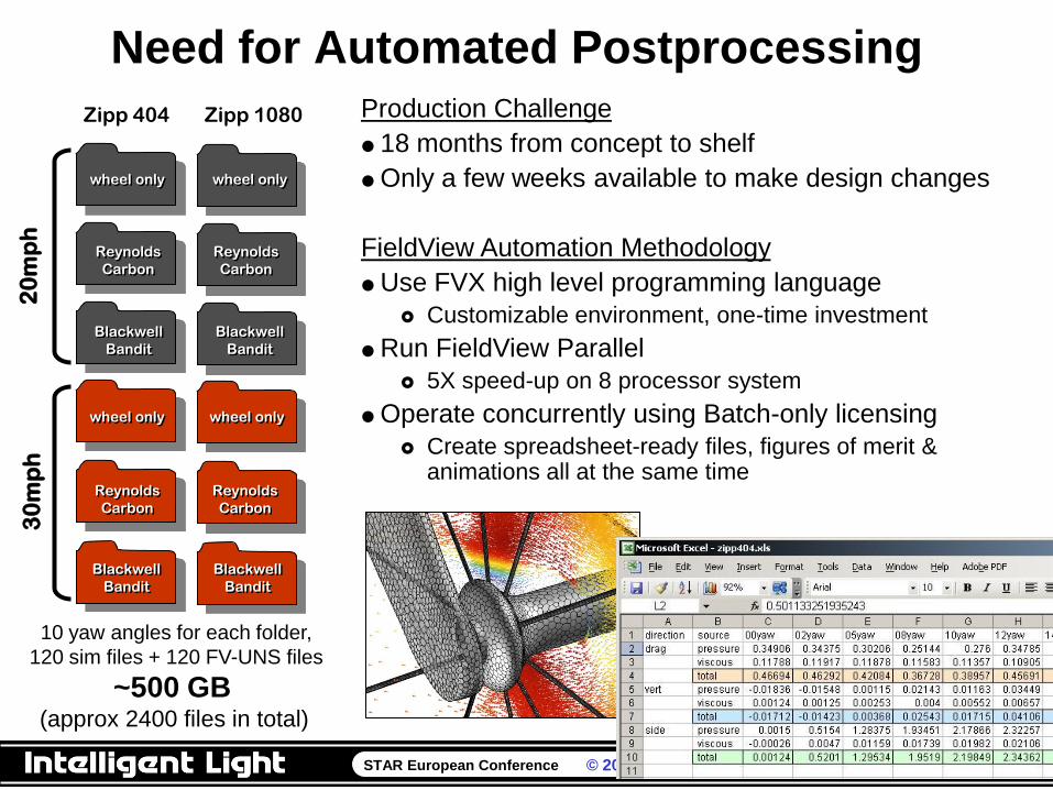
Need for Automated Postprocessing2
0m
ph
30
mp
h
Zipp 404 Zipp 1080
wheel only
wheel onlywheel only
wheel only
Reynolds
Carbon
Reynolds
Carbon
Reynolds
Carbon
Reynolds
Carbon
Blackwell
Bandit
Blackwell
Bandit
Blackwell
Bandit
Blackwell
Bandit
10 yaw angles for each folder,
120 sim files + 120 FV-UNS files
~500 GB (approx 2400 files in total)
Production Challenge
18 months from concept to shelf
Only a few weeks available to make design changes
FieldView Automation Methodology
Use FVX high level programming language
Customizable environment, one-time investment
Run FieldView Parallel
5X speed-up on 8 processor system
Operate concurrently using Batch-only licensing
Create spreadsheet-ready files, figures of merit & animations all at the same time
STAR European Conference © 2010 Intelligent Light
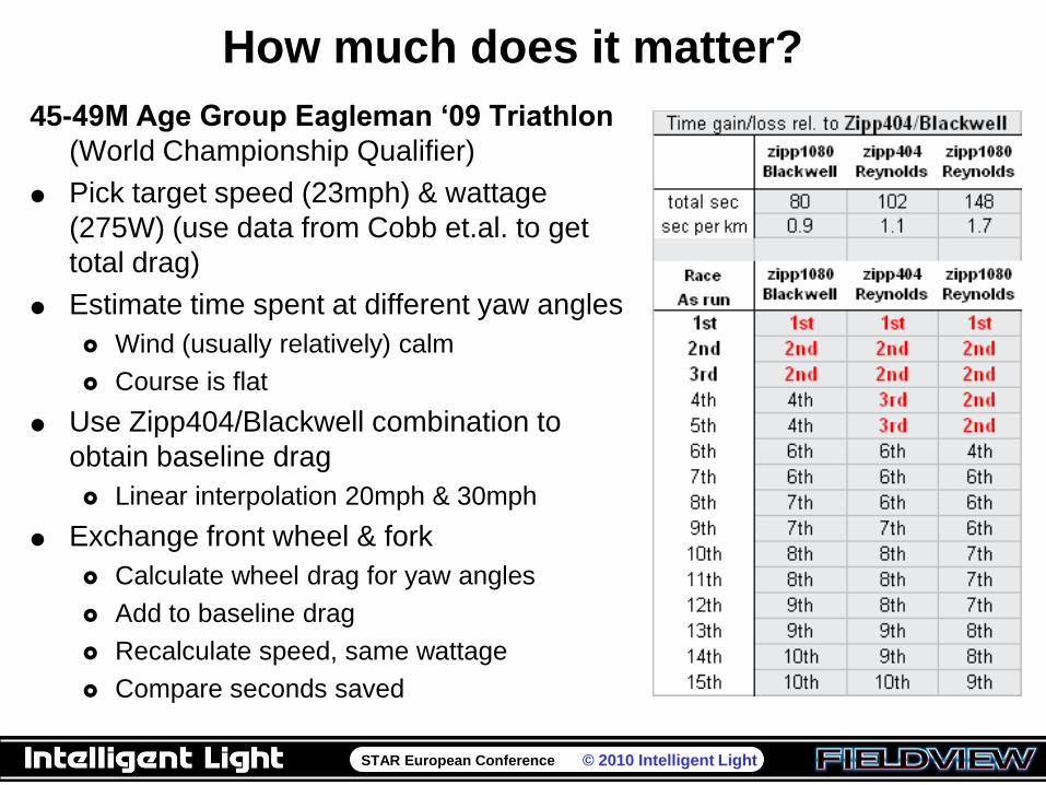
How much does it matter?
45-49M Age Group Eagleman ‘09 Triathlon
(World Championship Qualifier)
Pick target speed (23mph) & wattage
(275W) (use data from Cobb et.al. to get
total drag)
Estimate time spent at different yaw angles
Wind (usually relatively) calm
Course is flat
Use Zipp404/Blackwell combination to
obtain baseline drag
Linear interpolation 20mph & 30mph
Exchange front wheel & fork
Calculate wheel drag for yaw angles
Add to baseline drag
Recalculate speed, same wattage
Compare seconds saved
STAR European Conference © 2010 Intelligent Light
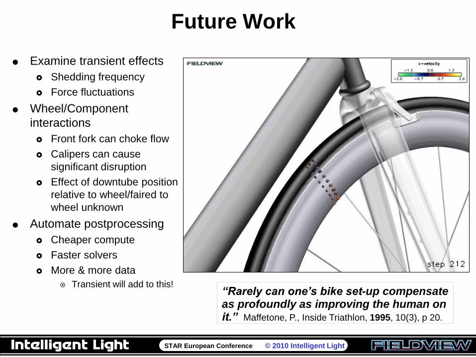
Future Work
Examine transient effects
Shedding frequency
Force fluctuations
Wheel/Component
interactions
Front fork can choke flow
Calipers can cause
significant disruption
Effect of downtube position
relative to wheel/faired to
wheel unknown
Automate postprocessing
Cheaper compute
Faster solvers
More & more data
Transient will add to this!“Rarely can one‟s bike set-up compensate as profoundly as improving the human on it.” Maffetone, P., Inside Triathlon, 1995, 10(3), p 20.