spitfire aerodynamic analysis (cfd)
TRANSCRIPT
CFD – Aerodynamic Analysis
JOSUÉ MARTE GRANADOS RAMOS 965898
LUIS FELIPE PACHECO FLORES 968221
GERARDO BALTIERRA UREÑA 987708
VÍCTOR MANUEL GUTIÉRREZ LÓPEZ 1161698
DANIEL ALFONSO VELÁZQUEZ LECHUGA 1180365
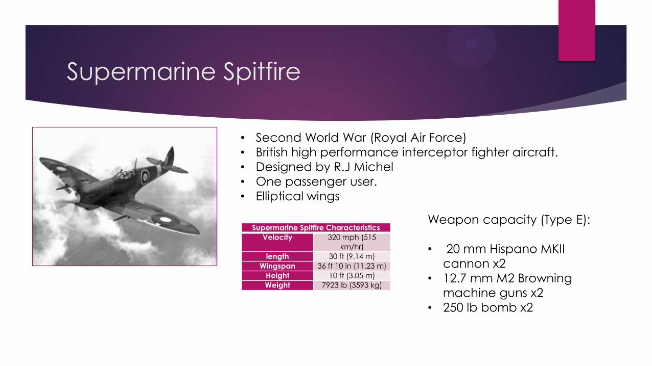
Supermarine Spitfire
• Second World War (Royal Air Force)
• British high performance interceptor fighter aircraft.
• Designed by R.J Michel
• One passenger user.
• Elliptical wings
Supermarine Spitfire Characteristics
Velocity 320 mph (515
km/hr)
length 30 ft (9.14 m)
Wingspan 36 ft 10 in (11.23 m)
Height 10 ft (3.05 m)
Weight 7923 lb (3593 kg)
Weapon capacity (Type E):
• 20 mm Hispano MKII
cannon x2
• 12.7 mm M2 Browning
machine guns x2
• 250 lb bomb x2
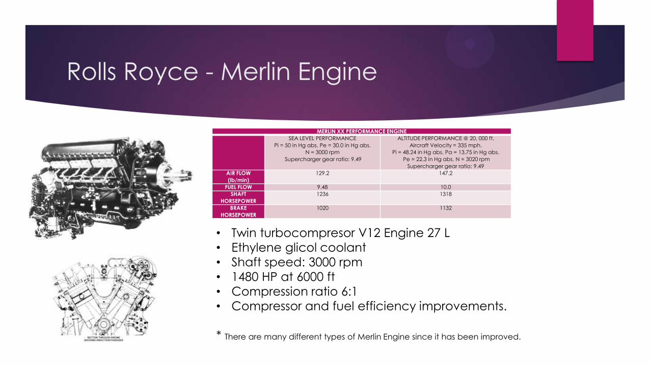
Rolls Royce - Merlin Engine
MERLIN XX PERFORMANCE ENGINE
SEA LEVEL PERFORMANCE
Pi = 50 in Hg abs. Pe = 30.0 in Hg abs.
N = 3000 rpm
Supercharger gear ratio: 9.49
ALTITUDE PERFORMANCE @ 20, 000 ft.
Aircraft Velocity = 335 mph.
Pi = 48.24 in Hg abs. Pa = 13.75 in Hg abs.
Pe = 22.3 in Hg abs. N = 3020 rpm
Supercharger gear ratio: 9.49
AIR FLOW
(lb/min)
129.2 147.2
FUEL FLOW 9.48 10.0
SHAFT
HORSEPOWER
1236 1318
BRAKE
HORSEPOWER
1020 1132
• Twin turbocompresor V12 Engine 27 L
• Ethylene glicol coolant
• Shaft speed: 3000 rpm
• 1480 HP at 6000 ft
• Compression ratio 6:1
• Compressor and fuel efficiency improvements.
* There are many different types of Merlin Engine since it has been improved.
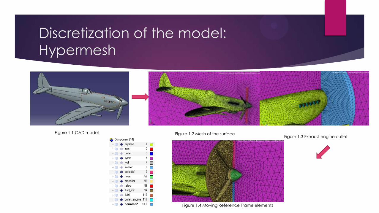
Discretization of the model:
Hypermesh
Figure 1.1 CAD model Figure 1.2 Mesh of the surfaceFigure 1.3 Exhaust engine outlet
Figure 1.4 Moving Reference Frame elements
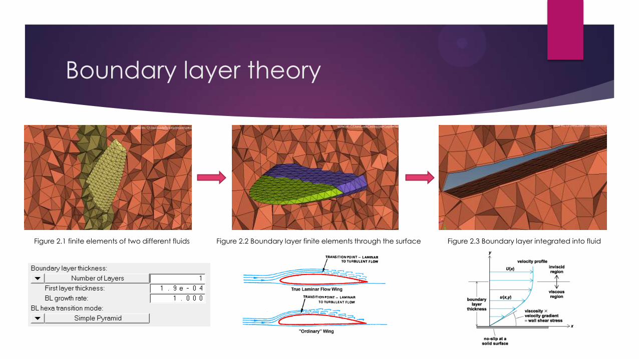
Boundary layer theory
Figure 2.2 Boundary layer finite elements through the surface Figure 2.3 Boundary layer integrated into fluidFigure 2.1 finite elements of two different fluids
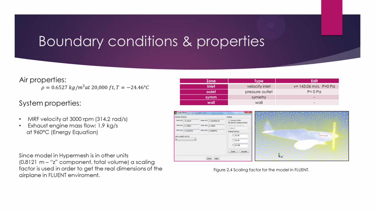
Boundary conditions & properties
Zone Type Edit
Inlet velocity inlet v= 143.06 m/s, P=0 Pa
oulet pressure outlet P= 0 Pa
symm symetry -
wall wall -
Figure 2.4 Scaling factor for the model in FLUENT.
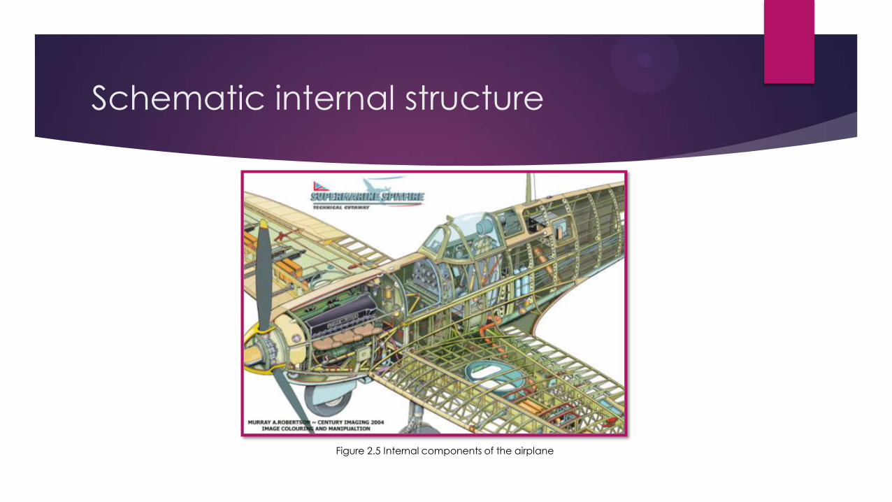
Schematic internal structure
Figure 2.5 Internal components of the airplane
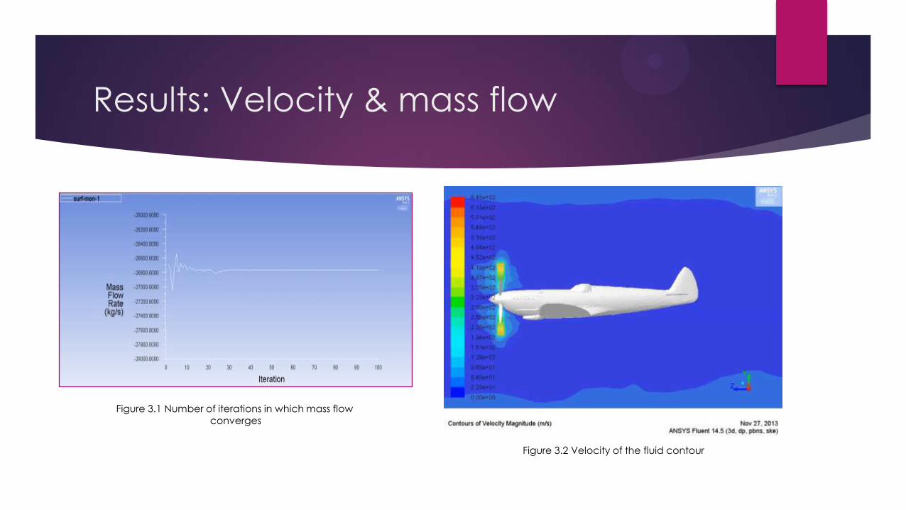
Results: Velocity & mass flow
Figure 3.1 Number of iterations in which mass flowconverges
Figure 3.2 Velocity of the fluid contour
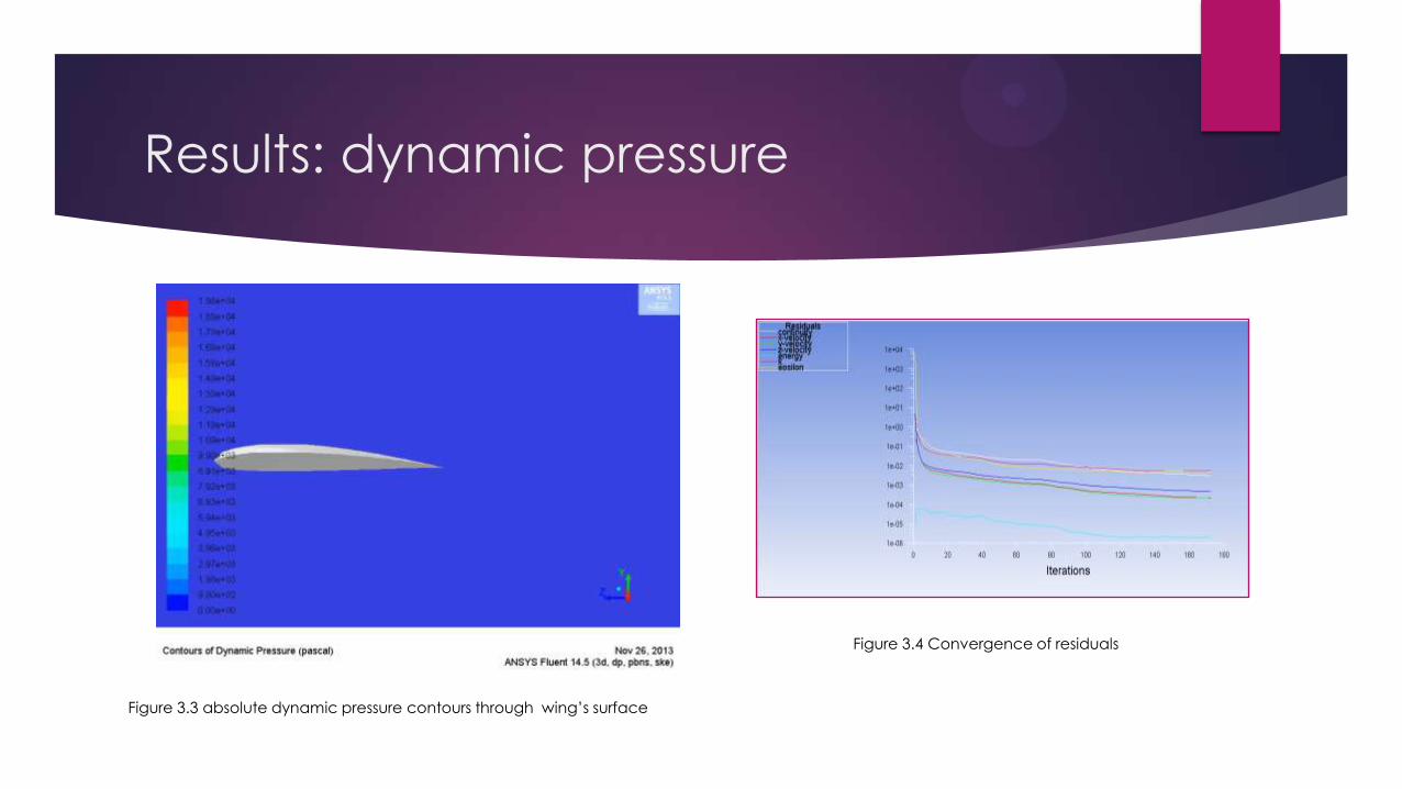
Results: dynamic pressure
Figure 3.4 Convergence of residuals
Figure 3.3 absolute dynamic pressure contours through wing’s surface
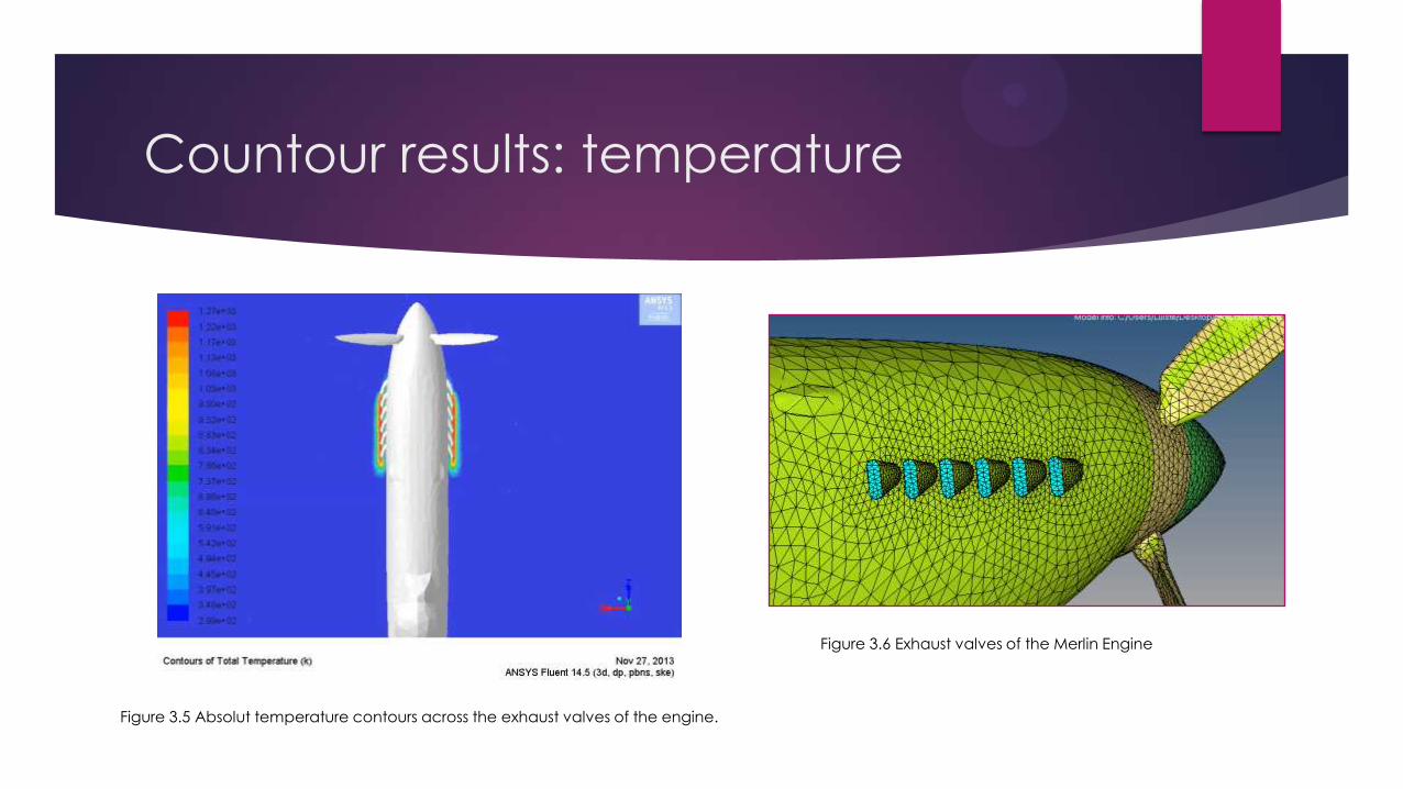
Countour results: temperature
Figure 3.6 Exhaust valves of the Merlin Engine
Figure 3.5 Absolut temperature contours across the exhaust valves of the engine.
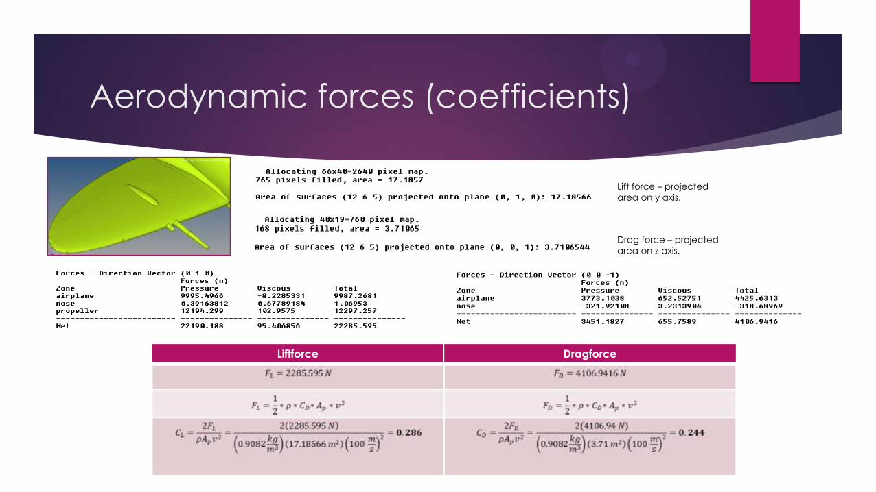
Aerodynamic forces (coefficients)
Drag force – projected
area on z axis.
Lift force – projected
area on y axis.
Liftforce Dragforce
Observations
Weapons contribute to increase the drag force
Density changes at high altitude
Merlin engine was improved in order to achieve better
efficiency
Lift and Drag coefficients are different through the
surface of the aircraft, there are presented the
maximum values.
Total area of the aircraft was considered.
References
White. F (2008). Fluid Mechanics. Mc Graw Hill
Lovesey, A.C (1945). Development of the Rolls-Royce Merlin from 1939 to1945. Retrieved at November 19, 2013 from: http://www.missbardahl.com/engine/hist/rr_merlin_dev.pdf
J. Raymond, R. (2011) Aircraft Engine Performance Analysis at Rolls-Royce ca. 1940. Retrieved at November 28, 2013 from: http://www.enginehistory.org/members/articles/ACEnginePerfAnalysisR-R.shtml
Royal AirForce (2013). Supermarine Spitfire. UK Crown. Retrieved at November 28, 2013 from: http://www.raf.mod.uk/history/supermarinespitfire.cfm