examining the aerodynamic performance of commercial bicycle racing wheels using cfd
TRANSCRIPT
Examining the Aerodynamic Performance of
Commercial Bicycle Racing Wheels using CFD
Matthew N. Godo, Ph.D.
FieldView Product Manager, Intelligent Light
David Corson,
Program Manager - AcuSolve, Altair Engineering
Steve M. Legensky
General Manager, Intelligent Light
Yves-Marie Lefebvre
Sales & Support Engineer, Intelligent Light
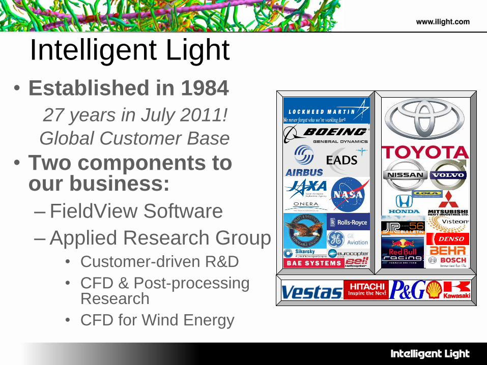
Intelligent Light
• Established in 1984
27 years in July 2011!
Global Customer Base
• Two components to our business:
– FieldView Software
– Applied Research Group • Customer-driven R&D
• CFD & Post-processing Research
• CFD for Wind Energy
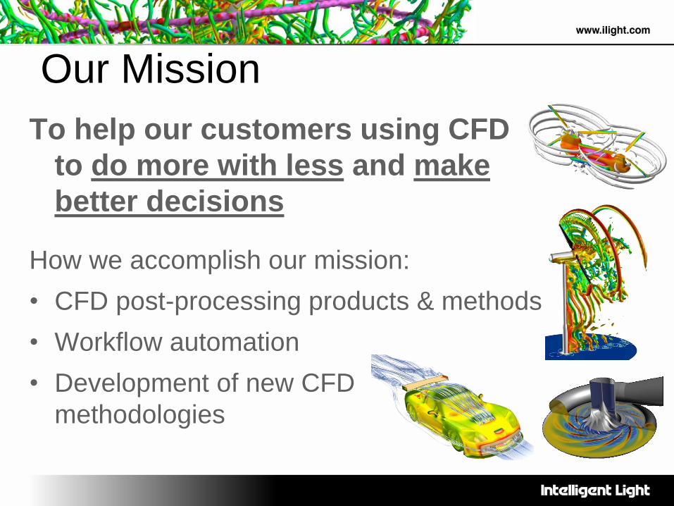
Our Mission
To help our customers using CFD
to do more with less and make
better decisions
How we accomplish our mission:
• CFD post-processing products & methods
• Workflow automation
• Development of new CFD
methodologies
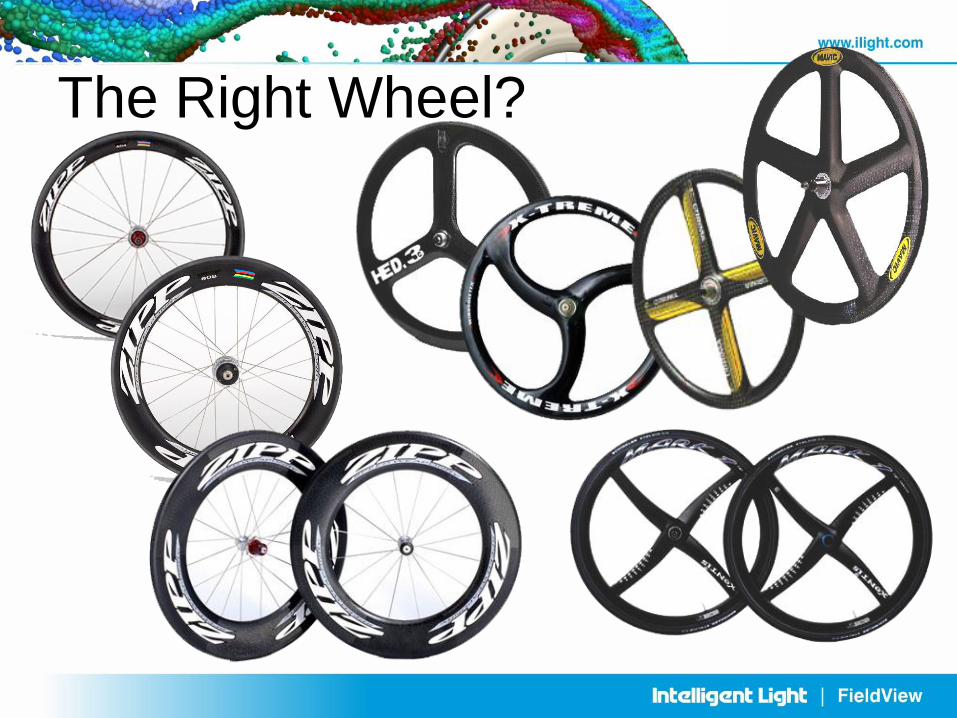
The Right Wheel?
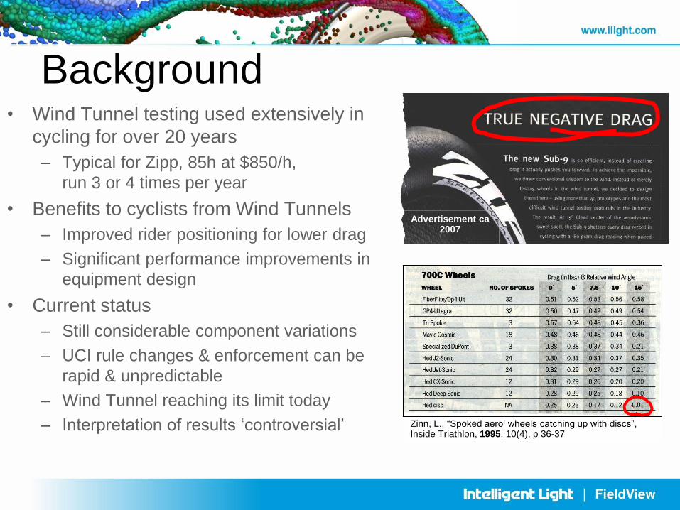
Background • Wind Tunnel testing used extensively in
cycling for over 20 years
– Typical for Zipp, 85h at $850/h,
run 3 or 4 times per year
• Benefits to cyclists from Wind Tunnels
– Improved rider positioning for lower drag
– Significant performance improvements in
equipment design
• Current status
– Still considerable component variations
– UCI rule changes & enforcement can be
rapid & unpredictable
– Wind Tunnel reaching its limit today
– Interpretation of results ‘controversial’ Zinn, L., “Spoked aero’ wheels catching up with discs”, Inside Triathlon, 1995, 10(4), p 36-37
Advertisement ca 2007
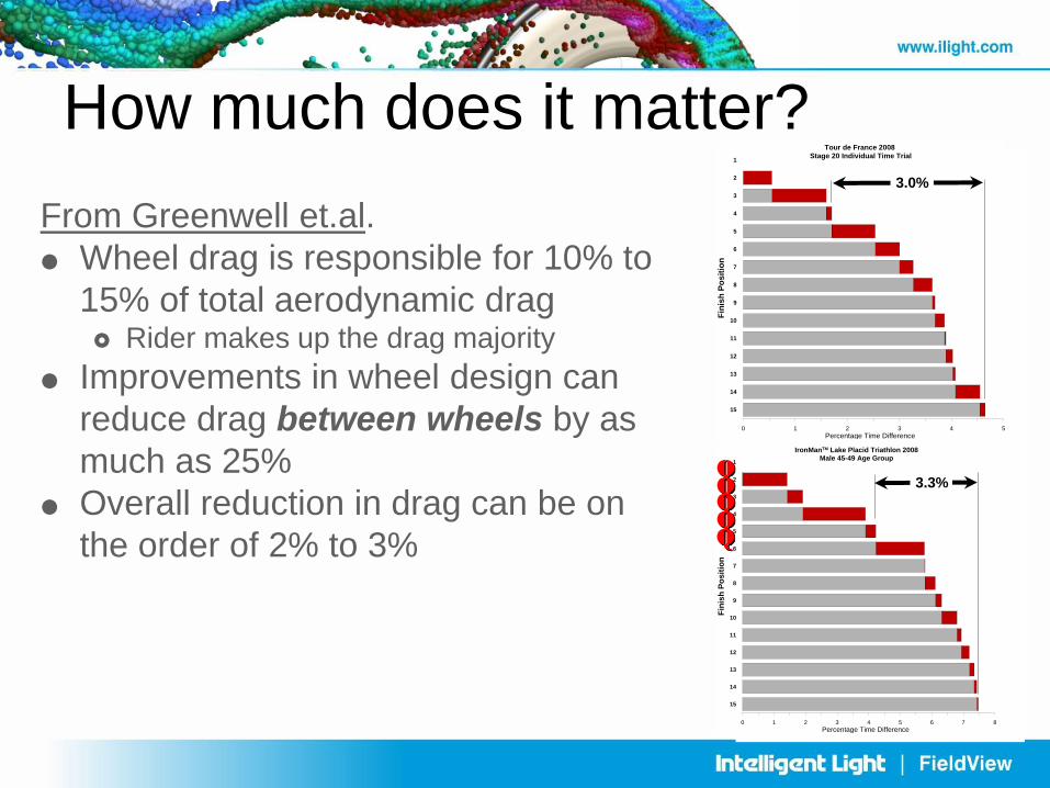
From Greenwell et.al.
Wheel drag is responsible for 10% to
15% of total aerodynamic drag Rider makes up the drag majority
Improvements in wheel design can
reduce drag between wheels by as
much as 25%
Overall reduction in drag can be on
the order of 2% to 3%
0 1 2 3 4 5
Percentage Time Difference
15
14
13
12
11
10
9
8
7
6
5
4
3
2
1
Fin
ish
Po
sit
ion
Tour de France 2008
Stage 20 Individual Time Trial
3.0%
0 1 2 3 4 5 6 7 8
Percentage Time Difference
15
14
13
12
11
10
9
8
7
6
5
4
3
2
1
Fin
ish
Po
sit
ion
IronManTM Lake Placid Triathlon 2008
Male 45-49 Age Group
3.3% Q Q Q Q Q
How much does it matter?
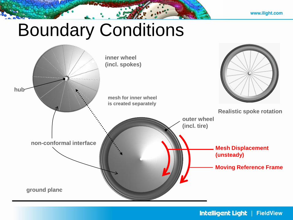
outer wheel
(incl. tire)
inner wheel
(incl. spokes)
non-conformal interface
ground plane
hub
mesh for inner wheel
is created separately
Boundary Conditions
Moving Reference Frame
Mesh Displacement
(unsteady)
Realistic spoke rotation
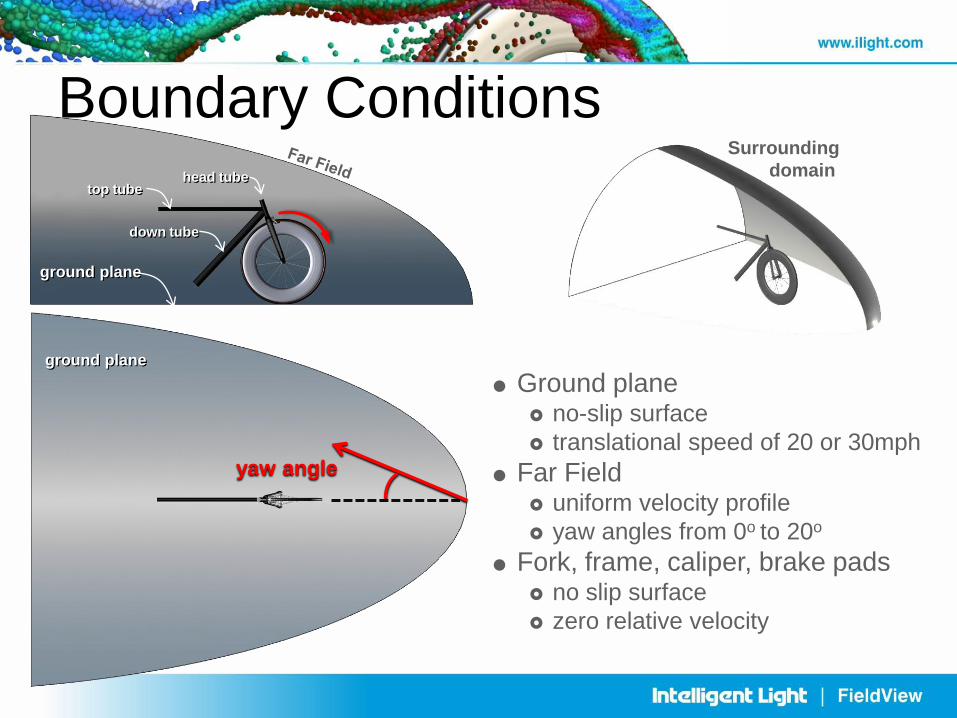
Boundary Conditions
yaw angle
Surrounding
domain
ground plane
top tube
down tube
head tube
ground plane
Ground plane no-slip surface
translational speed of 20 or 30mph
Far Field uniform velocity profile
yaw angles from 0o to 20o
Fork, frame, caliper, brake pads no slip surface
zero relative velocity
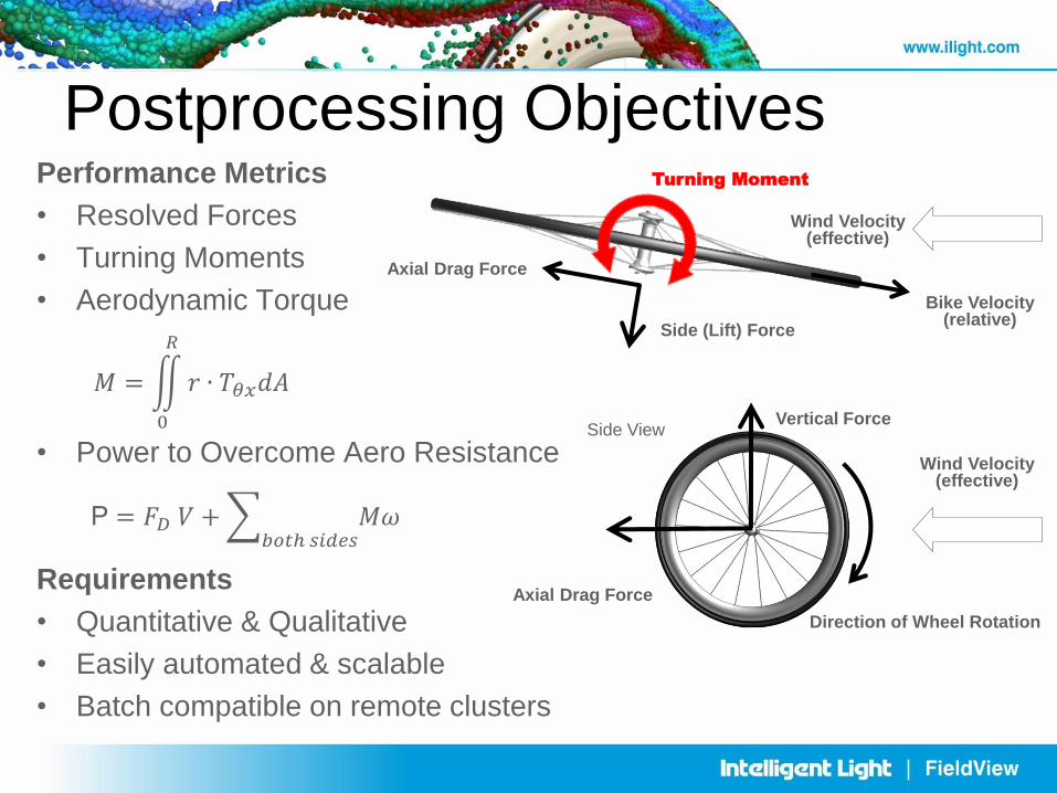
Postprocessing Objectives Performance Metrics
• Resolved Forces
• Turning Moments
• Aerodynamic Torque
• Power to Overcome Aero Resistance
Requirements
• Quantitative & Qualitative
• Easily automated & scalable
• Batch compatible on remote clusters
Side View
Axial Drag Force
Vertical Force
Direction of Wheel Rotation
Wind Velocity (effective)
Top View
Axial Drag Force
Side (Lift) Force
Bike Velocity (relative)
Wind Velocity (effective)
Turning Moment
P = 𝐹𝐷 𝑉 + 𝑀𝜔 𝑏𝑜𝑡ℎ 𝑠𝑖𝑑𝑒𝑠
𝑀 = 𝑟 ∙ 𝑇𝜃𝑥𝑑𝐴
𝑅
0
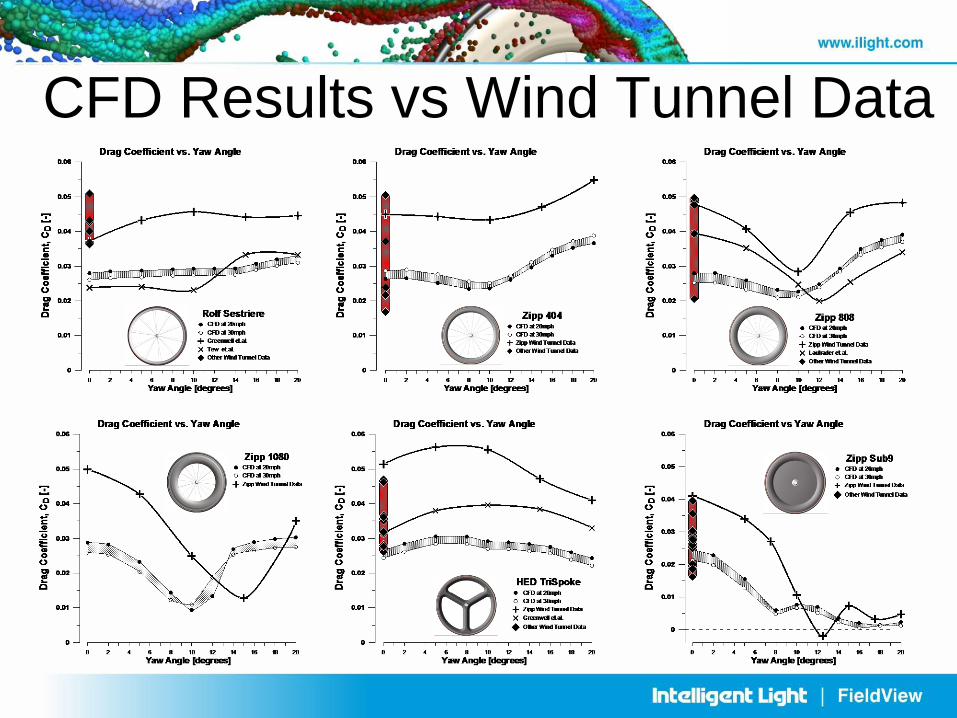
CFD Results vs Wind Tunnel Data
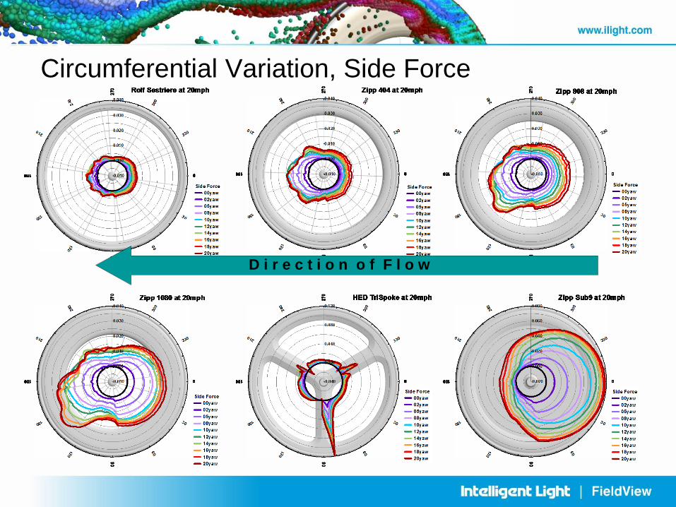
Circumferential Variation, Side Force
D i r e c t i o n o f F l o w
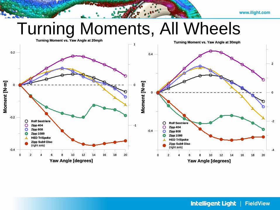
Turning Moments, All Wheels
0 2 4 6 8 10 12 14 16 18 20
Yaw Angle [degrees]
-0.4
0
0.4
Mo
men
t [N
·m]
Rolf Sestriere
Zipp 404
Zipp 808
Zipp 1080
HED TriSpoke
Zipp Sub9 Disc
(right axis)-4
-2
0
2
Turning Moment vs. Yaw Angle at 30mph
0 2 4 6 8 10 12 14 16 18 20
Yaw Angle [degrees]
-0.4
-0.2
0
0.2
Mo
men
t [N
·m]
Rolf Sestriere
Zipp 404
Zipp 808
Zipp 1080
HED TriSpoke
Zipp Sub9 Disc
(right axis)
-1
0
1
Turning Moment vs. Yaw Angle at 20mph
0 2 4 6 8 10 12 14 16 18 20
Yaw Angle [degrees]
-0.4
0
0.4
Mo
men
t [N
·m]
Rolf Sestriere
Zipp 404
Zipp 808
Zipp 1080
HED TriSpoke
Zipp Sub9 Disc
(right axis)-4
-2
0
2
Turning Moment vs. Yaw Angle at 30mph
0 2 4 6 8 10 12 14 16 18 20
Yaw Angle [degrees]
-0.4
-0.2
0
0.2
Mo
men
t [N
·m]
Rolf Sestriere
Zipp 404
Zipp 808
Zipp 1080
HED TriSpoke
Zipp Sub9 Disc
(right axis)
-1
0
1
Turning Moment vs. Yaw Angle at 20mph
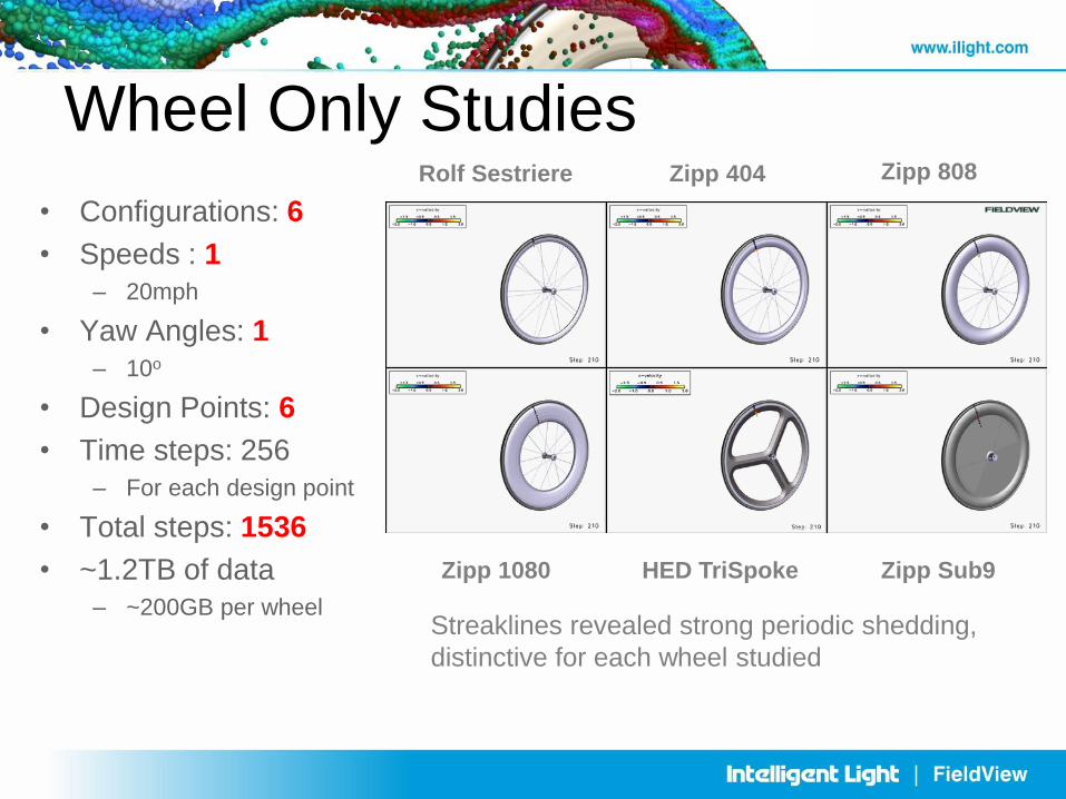
Wheel Only Studies
• Configurations: 6
• Speeds : 1
– 20mph
• Yaw Angles: 1
– 10o
• Design Points: 6
• Time steps: 256
– For each design point
• Total steps: 1536
• ~1.2TB of data
– ~200GB per wheel
Zipp 404
Zipp 1080 HED TriSpoke
Rolf Sestriere Zipp 808
Zipp Sub9
Streaklines revealed strong periodic shedding,
distinctive for each wheel studied
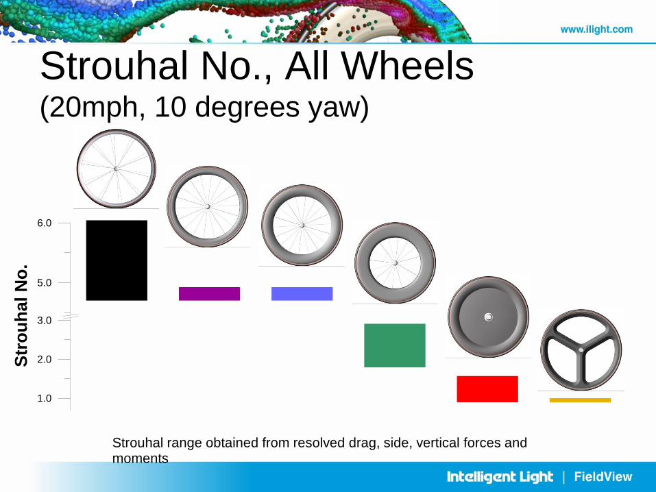
1.0
2.0
3.0
5.0
6.0
Str
ou
hal
No
.
Strouhal range obtained from resolved drag, side, vertical forces and moments
Strouhal No., All Wheels (20mph, 10 degrees yaw)
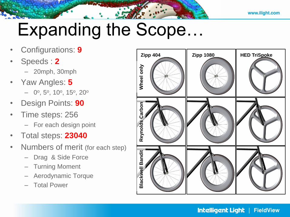
Expanding the Scope… • Configurations: 9
• Speeds : 2
– 20mph, 30mph
• Yaw Angles: 5
– 0o, 5o, 10o, 15o, 20o
• Design Points: 90
• Time steps: 256
– For each design point
• Total steps: 23040
• Numbers of merit (for each step)
– Drag & Side Force
– Turning Moment
– Aerodynamic Torque
– Total Power
Wh
ee
l o
nly
R
eyn
old
s C
arb
on
B
lac
kw
ell
Ban
dit
Zipp 404 Zipp 1080 HED TriSpoke
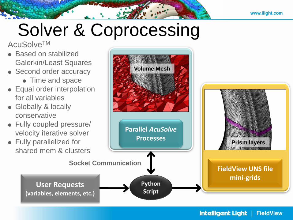
Solver & Coprocessing
Socket Communication
Python Script
User Requests (variables, elements, etc.)
Parallel AcuSolve Processes
Volume Mesh
FieldView UNS file mini-grids
Prism layers
AcuSolveTM
Based on stabilized
Galerkin/Least Squares
Second order accuracy
Time and space
Equal order interpolation
for all variables
Globally & locally
conservative
Fully coupled pressure/
velocity iterative solver
Fully parallelized for
shared mem & clusters
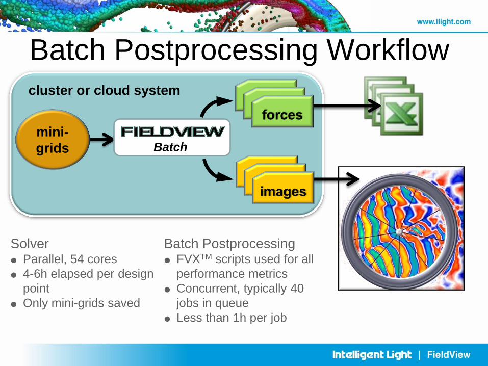
Batch Postprocessing Workflow cluster or cloud system
Batch
mini-
grids
forces forces
XDB XDB
forces
Solver
Parallel, 54 cores
4-6h elapsed per design
point
Only mini-grids saved
Batch Postprocessing
FVXTM scripts used for all
performance metrics
Concurrent, typically 40
jobs in queue
Less than 1h per job
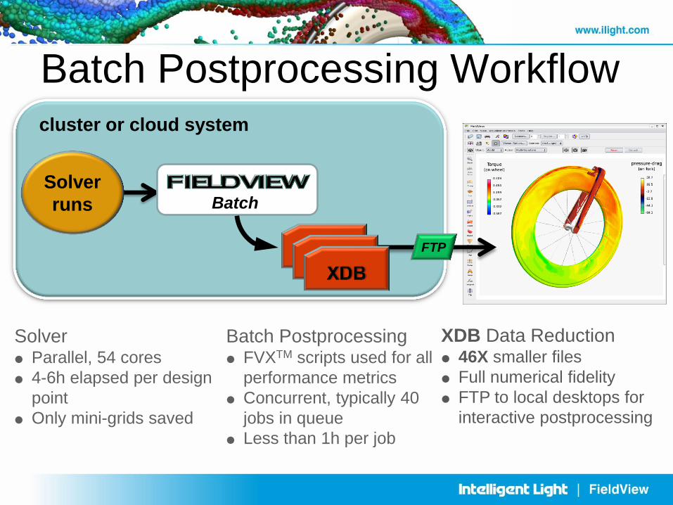
Batch Postprocessing Workflow cluster or cloud system
Batch
Solver
runs
XDB Data Reduction
46X smaller files
Full numerical fidelity
FTP to local desktops for
interactive postprocessing
XDB XDB
FTP
Solver
Parallel, 54 cores
4-6h elapsed per design
point
Only mini-grids saved
Batch Postprocessing
FVXTM scripts used for all
performance metrics
Concurrent, typically 40
jobs in queue
Less than 1h per job
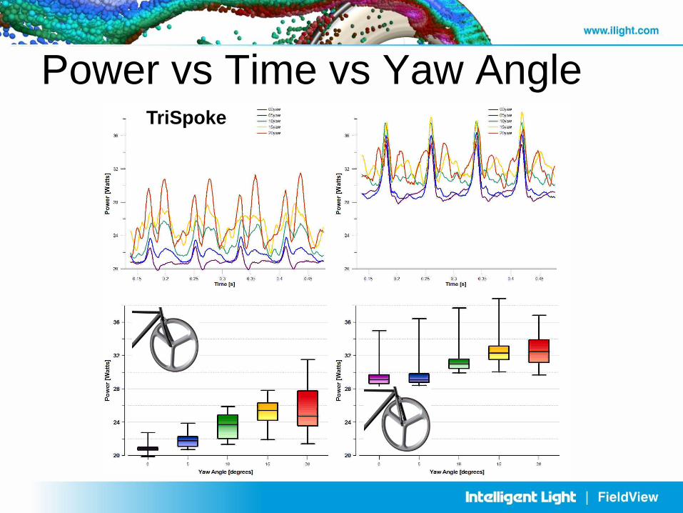
Power vs Time vs Yaw Angle TriSpoke
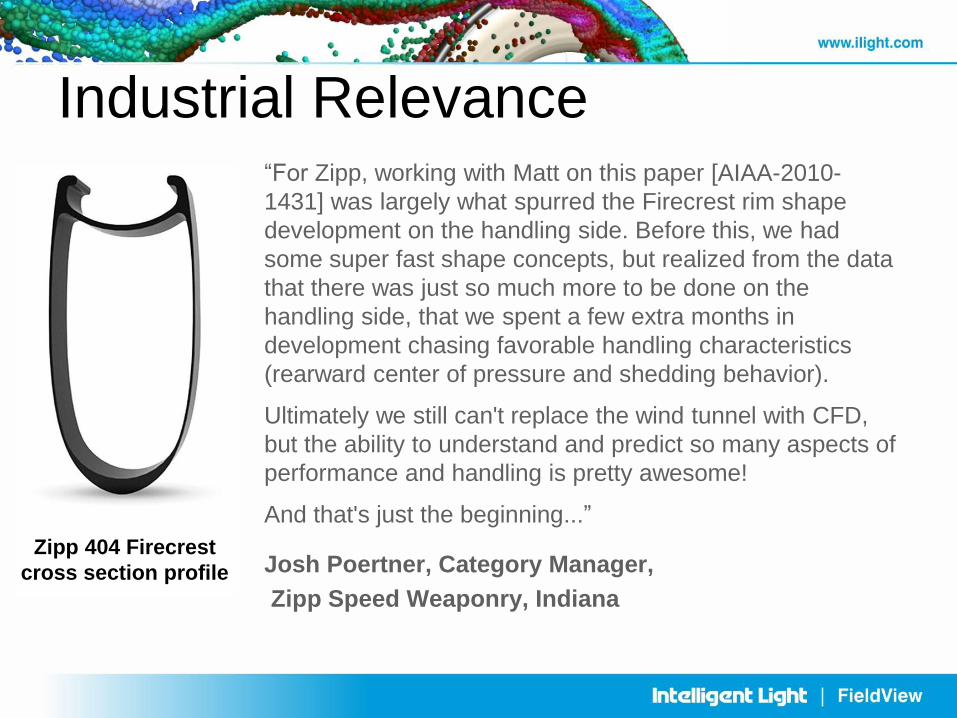
Industrial Relevance “For Zipp, working with Matt on this paper [AIAA-2010-
1431] was largely what spurred the Firecrest rim shape
development on the handling side. Before this, we had
some super fast shape concepts, but realized from the data
that there was just so much more to be done on the
handling side, that we spent a few extra months in
development chasing favorable handling characteristics
(rearward center of pressure and shedding behavior).
Ultimately we still can't replace the wind tunnel with CFD,
but the ability to understand and predict so many aspects of
performance and handling is pretty awesome!
And that's just the beginning...”
Josh Poertner, Category Manager,
Zipp Speed Weaponry, Indiana
Zipp 404 Firecrest
cross section profile