technical specification for public address system … · technical specification for public address...
TRANSCRIPT

3 X 660 MW NORTH KARANPURA STPP
VOLUME – IIB
TECHNICAL SPECIFICATION FOR
PUBLIC ADDRESS SYSTEM
BHEL DOCUMENT NO. : PE-TS-405-557-E001, REV-00
BHARAT HEAVY ELECTRICALS LIMITED POWER SECTOR
PROJECT ENGINEERING MANAGEMENT NOIDA – 201301

Doc. No PE-TS-405-557-E001
3 X 660 MW NORTH KARANPURA STPP Volume: IIB
Section
TECHNICAL SPECIFICATION FOR PUBLIC ADDRESS SYSTEM
Rev. : 00
Page : 1 of 1
CONTENTS
S.NO. CONTENT PAGE NO. VOLUME II B:
1. INSTRUCTIONS TO BIDDERS FOR PREPARING TECHNICAL OFFERS 1
2. PREAMBLE 2 3. SECTION-A
SCOPE OF SUPPLY 1
4. SECTION-B PROJECT INFORMATION 7
5. SECTION-C SPECIFIC TECHNICAL REQUIREMENTS 9 ANNEXURE 1- ZONE WISE DISTRIBUTION OF HANDSET STATIONS & PLOT PLAN 5 ANNEXURE 2- BILL OF QUANTITY 5 ANNEXURE 3- PA SYSTEM DRAWINGS & DOCUMENTS 1 ANNEXURE4-LIST OF DRAWINGS/ DOCUMENTS DISTRIBUTION 1 ANNEXURE 5- QUALITY PLAN 7 ANNEXURE 6- LIST OF TYPE TEST FOR PUBLIC ADDRESS SYSTEM 1
6. SECTION-D STANDARD SPECIFICATION OF PUBLIC ADDRESS SYSTEM 26 DATA SHEET-A 4 DATA SHEET-C 6 TOTAL NO. OF SHEETS = 87 (INCLUDING COVER SHEET,CONTENT SHEET & SEPARATOR SHEETS) IT IS CONFIRMED THAT OUR TECHNICAL OFFER COMPLIES WITH THE SPECIFICATION IN TOTAL & THAT THERE ARE NO TECHNICAL DEVIATIONS. ---------------------------------------------------------------------
BIDDER’S STAMP & SIGNATURE

VOLUME – II B

Doc. No. PE-TS-405-557-E001
3 X 660 MW NORTH KARANPURA STPP Volume Section
IIB
TECHNICAL SPECIFICATION FOR PUBLIC ADDRESS SYSTEM
Rev. : A
Page : 1 of 1
INSTRUCTIONS TO BIDDERS FOR PREPARING TECHNICAL OFFERS
1. Two signed and stamped copies of the following shall be furnished by all bidders as technical offer :
a. Unpriced Price Schedule (Annexure-2A,2B,2C,2D & 2E) with bidder’s
signature and company stamp. b. A copy of this sheet (“Instructions to Bidders for Preparing Technical
Offer”), with bidder’s signature and company stamp. c. A copy of previous sheet (“List of Contents”), with bidder’s signature and
company stamp.
2. No technical submittal such as copies of type test certificates, data Sheets, write-up, drawing, technical literature, etc. is required during tender stage. Any such submission, even if made, shall not be considered as part of offer.
3. Confirmations/ comments (if any) regarding delivery schedules shall be furnished as
part of the commercial offer. Any reference elsewhere/ covering letter of technical offer shall not be considered by BHEL.
4. Any comments/ clarifications on technical/ inspection requirements furnished as part
of bidder’s covering letter shall not be considered by BHEL, and bidder’s offer shall be construed to be in conformance with the specification.
5. Any changes made by the bidder in the price schedule with respect to the item
description/ quantities, notes etc. from those given in Annexure-2 of specification [Bill Of Quantities] shall not be considered (i.e., technical description, quantities, notes etc. as per specification shall prevail).
--------------------------------------------------------------------- BIDDER’S STAMP & SIGNATURE

Doc. No PE-TS-405-557-E001
3 X 660 MW NORTH KARANPURA STPP Volume: IIB
Section
TECHNICAL SPECIFICATION FOR PUBLIC ADDRESS SYSTEM
Rev. : 00
Page : 1 of 2
PREAMBLE 1.0 The Tender documents contain two (2) volumes. The bidder shall meet the requirements of all
the volumes. 1.1 VOLUME - I CONDITIONS OF CONTRACT This consists of four parts as below:- Volume – IA This part contains Instructions to bidders for making bids to BHEL. Volume – IB This part contains General Commercial Conditions of the Tender & includes provision that vender shall be responsible for the quality of item supplied by their sub-vendors. Volume – IC This part contains Special Conditions of Contract. Volume – ID This part contains Commercial conditions for Erection & Commissioning site work, as applicable. 1.2 VOLUME – II TECHNICAL SPECIICATIONS Technical requirements are stipulated in Volume – II, which comprises of:- Volume – IIA General Technical Conditions. Volume – IIB Technical Specification including Drawings, if any. 1.2.1 VOLUME – IIB This volume is sub-divided in to following sections:- Section – A This section outlines the Intent of Specification Section – B This section provides “Projection Information”. Section – C This section indicates Technical Requirements specific to Contract, not covered in Section - D Section – D This section comprises of Technical Specifications of Equipments Complete with Data Sheets A , B , C.

Doc. No PE-TS-405-557-E001
3 X 660 MW NORTH KARANPURA STPP Volume: IIB
Section
TECHNICAL SPECIFICATION FOR PUBLIC ADDRESS SYSTEM
Rev. : 00
Page : 1 of 2
Data sheet - A :- Specific data and other requirements pertaining to the equipments. Data sheet – B :- Indicates data / documents to be furnished at the time of submission of Offer by vendor Data sheet – C :- Indicates data / documents to be furnished after the award of
Contract as per agreed schedule by the vendor (as applicable)

SECTION – A
SCOPE OF SUPPLY

Doc. No PE-TS-405-557-E001
3 X 660 MW NORTH KARANPURA STPP Volume: IIB
Section :A
TECHNICAL SPECIFICATION FOR PUBLIC ADDRESS SYSTEM
Rev. : 00
Page : 1 of 1
SCOPE OF SUPPLY
1. This specification covers the design, manufacture, inspection and testing at manufacturer's works, proper packing and delivery to site, system engineering, testing, erection and commissioning of PUBLIC ADDRESS SYSTEM as mentioned in different sections of this specification for 3 X 660 MW NORTH KARANPURA STPP.
2. It is not the intent to specify herein all the details of design & manufacture.
However, the equipment shall conform in all respects to high standards of design, engineering and workmanship and shall be capable of performing in continuous commercial operation.
3. The general terms and conditions, instructions to bidders and other attachment
referred to elsewhere are hereby made part of the Technical Specification.
4. The bidders shall be responsible for and governed by all requirements stipulated hereinafter.
5. The documents shall be in English language and MKS system of units.
6. Bidder shall quote for all type of PA system items as per specification, failing
which their offer shall be rejected.
7. For every shipment made to site, a shipping list containing item reference (item no. & description as per specification Bill of material of package drawing) and quantity of the same (nos.) shall be provided by the vendor at the time of dispatch of material to site.

SECTION – B
PROJECT INFORMATION

CLAUSE NO.
PROJECT INFORMATION
NORTH KARANPURA STPP
(3 X 660 MW)
EPC PACKAGE
TECHNICAL SPECIFICATION
SECTION – VI, PART-A
BID DOC. NO.:CS-4410-001-2
SUB-SECTION-IB
PROJECT INFORMATION
PAGE
1 OF 10
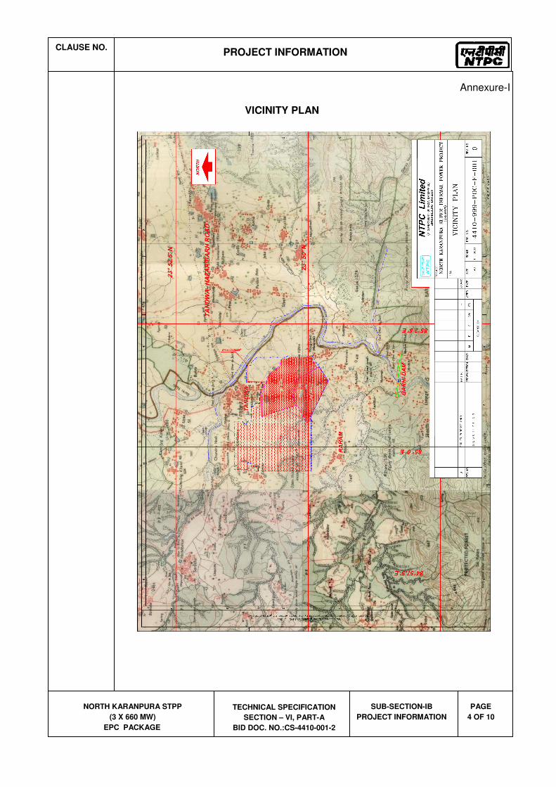
1.00.00 BACKGROUND North Karanpura Super Thermal Power Project (3x660 MW), a pit head coal based thermal
power project, is located in Hazaribagh and Chatra districts of Jharkhand State. Basic inputs i.e. coal, water and land have already been tied up. The project is proposed for the States & Union Territories of Northern, Western and Eastern Regions and the State of Jharkhand.
The capacity of the project is 1980 MW comprising of three (3) units of 660 MW each. 1.01.00 Location and Approach The power project is proposed to be located near Tandwa town in Chatra districts in the
state of Jharkhand on Hazaribagh-Chatra State highway at a distance of about 50 kms from Hazaribagh city. The nearest commercial airport is Ranchi at a distance of 150 kms from project site. The nearest railhead Khalari Railway Station on Ranchi-Garhwa section of Eastern Railways is about 40 kms from project site.
Major rail/road distances from the project site are as under:
City
Distance Approx. (kms)
Ranchi : 150
Khalari : 40
The site is located near Tandwa town having latitude and longitude of about 23
0 50’ N to
23º 52’ N and 840 59’ E to 85º 2’ E respectively. The Vicinity Plan of the project is placed at
Annexure-I. Further to the information given in this sub-section, Bidders are also advised to visit the
project site and collect data on local site conditions.
1.02.00 Land
About 2245 acres of land is being acquired for the project. About 1500 acres of land is under possession/legal possession and out of 1500 acres, about 890 acres of land is to be used for plant, ash dyke and initial enabling township. No additional land is envisaged to be acquired in plant area. About 15 acres of land is envisaged to be acquired in Hazaribagh city for Township. Commissioner, Chatra vide dated 25.05.1999 and 14.06.2000 has given in-principle clearance for NKSTPP.
1.03.00 Water
Make up water available for this project would be about 22 cusec and will be arranged by constructing a dam/reservoir across river Garhi.
1.04.00 Fuel (Coal)
1.04.01 Coal Requirement, Availability and Linkage
Coal requirement for the project is estimated as 10.6 Million Tonne/Annum (MTPA), considering a GCV of 3800 kcal/kg. Ministry of Coal vide letter dated 21.10.99 accorded in-principle coal linkage of 10.00 MTPA subject to ratification by Standing Linkage Committee-Long Term (SLC (LT)), of MOC. SLC (LT) in its meeting held on 15.12.2000 firmed up the coal linkage of 10.24 MTPA for the project. Subsequently, the coal linkage was withdrawn by SLC (LT) in its meeting held on 22/23.10.08.

CLAUSE NO.
PROJECT INFORMATION
NORTH KARANPURA STPP
(3 X 660 MW)
EPC PACKAGE
TECHNICAL SPECIFICATION
SECTION – VI, PART-A
BID DOC. NO.:CS-4410-001-2
SUB-SECTION-IB
PROJECT INFORMATION
PAGE
2 OF 10
Cabinet Committee on Investment (GOI) in its meeting on 20.02.13 decided in-principle to restore the original coal linkage granted to NKSTPP (i.e. from Magadh Coal Block) with the stipulation that the coal supply will commence during the 13th Five Year Plan. MOC vide letter dated 09.05.2013 restored the coal linkage with the stipulation that the coal supply will commence during the 13
th five year plan.
1.04.02 Coal Transportation
Coal from Magadh block of North Karanpura Coalfields is proposed to be transported to the project site through conveyor belt system. One external coal handling plant and one internal coal handling plant are envisaged.
1.05.00 Meteorological Data Important meteorological data from nearest observatory at Hazaribag is placed at
Annexure-II. 1.06.00 Plant Water Scheme
The Plant water scheme is described below.
1.06.01 Condenser Cooling System
It is proposed to adopt Air Cooled Condenser for the project.
1.06.02 Equipment Cooling Water (ECW) System (Unit Auxiliaries)
All plant auxiliaries shall be cooled by De-mineralized water (DM) in a closed circuit. The primary circuit DM water shall be cooled through heat exchangers by auxiliary cooling water system. The hot secondary circuit cooling water shall be cooled in the cooling towers and shall be returned back to the system.
1.06.03 Ash Water System
It is proposed to have HCSD (High concentration Slurry Disposal) system for combined fly ash and bottom ash. No recirculation of ash water from ash disposal area is envisaged.
1.06.04 Other Miscellaneous Water Systems
(a) Raw water shall be used for meeting the Fly ash and bottom ash system requirement etc.
(b) The service water shall be taken from clarified water tank of Pretreatment plant. Service water (wash water) collected from various areas shall be treated using oil water separators, tube settlers, coal settling pits etc. as per requirement and treated water from liquid effluent treatment plant shall be recycled back to the service water system for re-use.
(c) The drinking water requirement of the plant shall be provided from water treatment plant.

CLAUSE NO.
PROJECT INFORMATION
NORTH KARANPURA STPP
(3 X 660 MW)
EPC PACKAGE
TECHNICAL SPECIFICATION
SECTION – VI, PART-A
BID DOC. NO.:CS-4410-001-2
SUB-SECTION-IB
PROJECT INFORMATION
PAGE
3 OF 10
(d) Steam Cycle make-up water, makeup to the primary circuit of ECW (unit auxiliaries) system, boiler fill water and makeup to the hydrogen generation plant shall be provided from Demineralising plant.
(e) The quality of Raw water is enclosed with this sub-section as Annexure-III.
1.07.00 Criteria for Earthquake Resistant Design of Structures and Equipment All power plant structures and equipment, including plant auxiliary structures and
equipment shall be designed for seismic forces as given in the Part - B of this section. 1.08.00 Criteria for Wind Resistant Design of Structures and Equipment All structures and equipment of the power plant, including plant auxiliary structures and
equipment, shall be designed for wind forces as given as given in Part B of this section.
CLAUSE NO.
PROJECT INFORMATION
NORTH KARANPURA STPP
(3 X 660 MW)
EPC PACKAGE
TECHNICAL SPECIFICATION
SECTION – VI, PART-A
BID DOC. NO.:CS-4410-001-2
SUB-SECTION-IB
PROJECT INFORMATION
PAGE
4 OF 10
Annexure-I
VICINITY PLAN

CLAUSE NO.
PROJECT INFORMATION
NORTH KARANPURA STPP
(3 X 660 MW)
EPC PACKAGE
TECHNICAL SPECIFICATION
SECTION – VI, PART-A
BID DOC. NO.:CS-4410-001-2
SUB-SECTION-IB
PROJECT INFORMATION
PAGE
5 OF 10
Annexure-II
CLIMATOLOGICAL TABLE

CLAUSE NO.
TECHNICAL REQUIREMENTS
NORTH KARANPURA STPP
(3 X 660 MW) EPC PACKAGE
TECHNICAL SPECIFICATIONS SECTION – VI, PART-B
SUB-SECTION-B0 GENERAL ELECTRICAL
SPECIFCIATION
PAGE 1 OF 11
1.00.00 General Requirements
1.01.00 For the purpose of design of equipment/systems, an ambient temperature of 50 deg. Centigrade and relative humidity of 95% shall be considered. The equipment shall operate in a highly polluted environment. However, for equipment in air conditioned areas, design ambient temperature shall be 35 deg.C, if 2x100% air conditioning system is provided.
1.02.00 All equipments shall be suitable for rated frequency of 50Hz with a variation of +3% & -5%, and 10% combined variation of voltage and frequency unless specifically brought out in the specification. The step-up voltage level for the project shall be 400 KV. The turbo generator unit will be connected to its own step-up transformers for feeding power into the EHV grid. The overall system shall be designed considering voltage variation of +/- 5% and fault level of 50kA for 400KV and 40kA for 220 KV system. Under black start condition the minimum fault level of 1000 MVA shall be considered at 400KV voltage level and voltage variation at 400kV may be considered as +/-10% till system stabilization.
1.03.00 Contractor shall provide fully compatible electrical system, equipments, accessories and services for the entire station/plant in his scope as well as those specifically required by the Employer.
1.04.00 All the equipment, material and systems shall, in general, conform to the latest edition of relevant National and International Codes & Standards, especially the Indian Statutory Regulations.
1.05.00 The auxiliary AC voltage supply arrangement shall have 33 kV, 11 kV, 3.3KV and 415V systems. It shall be designed to limit voltage variations as given below under worst operating condition:
a) 33KV/11KV/3.3KV (MV) +/- 6%
b) 415 V/240 V +/- 10%
c) 220V DC -15% to +10% However the nominal continuous DC power supply shall be 240V.
1.06.00 The voltage level for motors shall be as follows:
a) Upto 0.2 KW : Single phase 240V AC / 3 phase
415V AC
b) Above 0.2 KW and upto 200 KW : 3 phase, 415V AC
c) Above 200 KW and upto 1500 KW : 3 phase, 3.3 kV AC
d) Above 1500 KW : 11 kV
The bidder may adopt 415V/3.3 KV for the drives rated in the range of 160-210 KW.
For CHP conveyor motor’s rating above 160 kW, 3.3 KV, three phase AC supply is to be used.
The voltage rating of the drives indicated above is for basic guideline. Minor variations in above can be accepted on case to case basis based on techno-economic considerations of the various sub-systems.
Voltage rating for special purpose motors viz, VFD and screw compressors, shall be as per manufacturer’s standard. All the motors ratings on Stacker/ reclaimer shall be 415V ac supply only.
PROJECT INFORMATION

CLAUSE NO.
TECHNICAL REQUIREMENTS
NORTH KARANPURA STPP
(3 X 660 MW) EPC PACKAGE
TECHNICAL SPECIFICATIONS SECTION – VI, PART-B
SUB-SECTION-B0 GENERAL ELECTRICAL
SPECIFCIATION
PAGE 2 OF 11
1.07.00 The preferred AC control supply voltage shall be 110V for all 415 V non breaker controlled feeders. Control supply voltages other than above may be offered by bidder based on the bidder’s standard proven practice.
1.08.00 The designed fault levels for 11 KV & 3.3 KV systems shall be restricted to 40 kA rms for 1 second and 50 kA rms for 1 second for 415 V systems. The 33 KV system equipments shall have a minimum short circuit fault withstand rating of 12.5 kA for 1 second.
1.09.00 The nominal voltage of main DC system shall be 220V. DC batteries shall be designed for continuous float operation with trickle charge, hence all the associated components like batteries, battery chargers, DC motors, relays, contactors, timers etc shall be suitable for continuous operation at the maximum continuous battery float voltage including suitable temperature correction factors. The operational limits of variation of DC voltage is (+)10 % to (-)15%.
In addition, the bidder may propose 110V, 48V or 24V systems as per requirements of control and instrumentation of his equipment and design.
1.10.00 The Contractor shall furnish calculations of maximum loading and fault levels under the most onerous conditions for the various equipment/systems as defined else where in the specification to prove adequacy of their parameters. In case any equipment or system is found to be inadequate, it shall be changed/ modified without any additional liability to the Employer.
1.11.00 Transformer voltage ratios, taps, impedances and tolerances thereon, shall be so optimised so that the auxiliary system voltages under various grid and loading conditions are always within permissible limits and equipment are not subjected to unacceptable voltages during operation and starting of motors such as MDBFP etc. The vector groups of the transformers shall be so selected that all the buses of particular voltage level have same vector within the plant.
1.12.00 In fire hazardous areas like gas/ liquid fuel storage/ handling areas, lighting fixtures, switchgears shall be flame proof.
1.13.00 The responsibility of coordination with electrical agencies /TAC/Pollution control board and obtaining all necessary clearances shall be of the contractor.
2.00.00 Provenness Criteria
Provenness of the Equipment, system, being offered by the bidder should satisfy the criteria Indicated in the “Provenness criteria” indicated elsewhere in the specification.
2.00.00 Electrical scheme for Electrical Power Distribution
The electrical schemes for the project as conceived by the Employer are indicated in Aux Power Supply Drawing No 4410-999-POE-J-001/J002/J003.
The scheme with minor variations to above may also be offered as long as they meet the redundancies indicated in the above drawings and sizing criterion specified.
2.01.00 The power supply shall be designed with unitized and Station load concept. All auxiliaries/systems required for operation of the unit like ID Fan, FD Fan, PA Fan, Coal Mills, BFP, CEP, CW System, ESP, Condenser cooling system, Ash Extraction etc. shall be fed from respective unit’s power supply system. Facilities/auxiliaries/systems required for more than one unit like Coal Handling, Ash Handling, Water System, Make up water, Fuel Oil, Aux Boiler etc. shall be fed from Station/ different unit’s power supply system as shown in the Electrical Single Line Diagram.
PROJECT INFORMATION

SECTION – C
SPECIFIC TECHNICAL REQUIREMENTS

Doc. No PE-TS-405-557-E001
3 X 660 MW NORTH KARANPURA STPP Volume: IIB
Section : C
TECHNICAL SPECIFICATION FOR PUBLIC
ADDRESS SYSTEM
Rev. : 00
Page : 1 of 7
1.0 INTENT OF SPECIFICATION
This specification covers the design, manufacture, assembly, testing and inspection at
vendor’s/sub-vendor’s works, packing, despatch to site, system engineering and erection &
commissioning of central exchange type Public Address System as described in the various
sections of this specification. Public Address System shall generally conform to IS. It is not
the intent to completely specify all details of design and construction herein.
2.0 SCOPE OF SUPPLY AND SERVICES
2.1 The scope of supply and services covers the complete supply of equipment and services for
central exchange type distributed amplifier Public Address System in accordance with the
requirements of various sections of this specification.
2.2 The scope of supply and E & C shall be as per Price Schedule enclosed as Annexure-2.
2.3 Public address system shall be provided for the entire plant including switchyard, CHP, AHP
and other offsite areas.
2.4 Consumables such as cable glands, cable lugs, ferrules, tags, self locking clamps, screws,
supports, fixing hardware and special supporting structure, as required for outdoor/indoor
equipment erection shall be included as part of supply. Wherever the quantity has been
specified as on as required basis, the same are to be supplied on as required basis without
any cost implication to the Contractor from the quoted lump sum price.
2.5 The successful bidder shall furnish the system write-up, complete erection/mounting drawing
for each of the equipment, testing & commissioning procedure for individual equipment and
for complete PA system during contract stage.
2.6 The Bidder's scope shall also include successful demonstration of performance testing
specified herein complete in all respects along with cables, junction boxes, ear th wire and
accessories like standard brackets, nut-bolts, glands, lugs, conduit sleeves, etc., as
required, to complete the proper installation conforming to IS: 1881, IS: 1882 of all the
equipments supplied as covered in this specification.
3.0 TERMINAL POINTS
Incoming power supply to Power Distribution Box (PDB)
4.0 POWER SUPPLY:
The system shall be suitable for operation from 240V AC 1-phase supply. For TG
building central exchange, there will be two UPS supply feeders. In event of failure of
one UPS supply, it will switch automatically to another UPS supply through auto
changeover.In CHP area, PA system shall be fed from UPS system.

Doc. No PE-TS-405-557-E001
3 X 660 MW NORTH KARANPURA STPP Volume: IIB
Section : C
TECHNICAL SPECIFICATION FOR PUBLIC
ADDRESS SYSTEM
Rev. : 00
Page : 2 of 7
5.0 ZONE WISE DISTRIBUTION OF SYSTEM
5.1 PA system shall comprise five separate zones:
a) Zone-I for Unit-1 area
b) Zone-II for Unit-2 area
c) Zone-III for Unit-3 area
d) Zone-IV for common plant area
e) Zone-V for coal handling area with two sub-zones, sub-zone-I and sub-zone-II.
5.2 All the above zones shall be connected with a central exchange to be located in Control
Equipment room of Unit-1. Another exchange to be located in Coal Handling Plant (CHP)
Control room, shall connect all the sub-zones of Coal Handling Plant. The Sub zones of CHP
areas shall be connected to the central exchange through this exchange only.
5.3 There will be three master control stations for central exchange for three units which will be
located in unit control room and another master control station parallel with earlier, shall be
located in shift incharge room. Another master control station shall be located in switchyard
control room. Each zone shall have number of subscriber stations. Each station can do
conversation with other stations and with master control station.
5.4 The master control station for CHP sub-exchange shall be located on CHP control desk. CHP
sub-exchange shall be connected to the central exchange for communication with other zones
from handsets in CHP sub-zones.
5.5 Typical utility block diagram of different zones & their interconnections is enclosed as per
dwg no: PE-DG-405-557-E001. Similarly the system block diagram for PA system is
enclosed as per dwg no: PE-DG-405-557-E002.
6.0 OPERATION:
6.1 Communication within a zone:
The system shall have two independent channels, which function simultaneously for communication viz page channel & party channel. Each of the two modes shall be open line, common talking type. Paging mode shall be used for locating a person and for general instructions. Party mode shall be used for conversation between individuals without broadcasting the same over the loudspeaker. Whenever the 'Press to page' push button is pressed on any of the handset stations, a pleasant chime shall be broadcast over all the loudspeaker except the one associated with that handset station to attract attention. Conversation, in paging mode shall be heard over all loudspeakers except the loudspeaker associated with the handset station whose 'Press to Page' push button is being held in pressed condition. When 'Press to Page' push button is released, the associated handset shall return to party mode.

Doc. No PE-TS-405-557-E001
3 X 660 MW NORTH KARANPURA STPP Volume: IIB
Section : C
TECHNICAL SPECIFICATION FOR PUBLIC
ADDRESS SYSTEM
Rev. : 00
Page : 3 of 7
During party channel mode, page channel is free to receive any announcement. A mute switch is provided to mute the associated loudspeaker, if required when engaged in party channel. Simultaneous operation on both modes, i.e. Some handsets on party channel and some handsets on paging channel, shall be possible without any crosswalk between the two channels. During conversation on 'page' mode within a zone, the centralised equipment/hardware of the associated zone shall have the feature to monitor and identify the handset from where conversation is being continued with the 'page' button depressed and the access code of the person.
6.2 Inter zone communication:
It shall be possible from a station in one zone to communicate with another station in a different zone, both in party/page mode through the master control units only located on each unit control desk at control room and shift Incharge room. Further, it shall be possible to broad cast recorded speech, music etc. over the loudspeakers.Communication/announcements within a zone shall not be heard in loudspeakers of other zones.
7.0 TYPES OF HANDSET STATIONS
Following types of handset stations are envisaged:
a) Type-A: Outdoor Wall/column mounted station with built-in amplifier and horn type
speaker. Degree of protection shall be IP 55 for main plant area and IP-65 for CHP area.
b) Type-B: Indoor desktop mounted station with cone type speaker. Degree of
protection shall be IP 32. c) Type-C: Indoor control desk Flush mounted type station with built-in amplifier and
speaker. Degree of protection shall be IP 32.
Each of the above handset station shall have following: One - telephone handset, One Cradle switch for resetting the handset.,, One "Press to Page" push button, One "Press to Mute Loudspeaker" push button,Pre-amplifier and Power amplifier, Indication for 'POWER SUPPLY ON' and Indication for 'PARTY CHANNEL BUSY’. The Type-A handset shall be inside an enclosure with transparent glass door which can be opened through number padlock only.
d) Type-D: Master control station with built-in amplifier and speaker. Degree of
protection shall be IP 32. e) Type-E: Portable station complete with handset, speaker, amplifier, push buttons,
indication lamps and coupling cable terminated by a plug.
f) Type-S: Socket for Portable Handset

Doc. No PE-TS-405-557-E001
3 X 660 MW NORTH KARANPURA STPP Volume: IIB
Section : C
TECHNICAL SPECIFICATION FOR PUBLIC
ADDRESS SYSTEM
Rev. : 00
Page : 4 of 7
Handset transmitter/microphone shall be noise canceling type and all switches and pushbuttons provided on the handset station shall be of encapsulated contact type. Handset transmitter/microphone shall have filters to protect from dust. Each handset shall be provided with one meter (extended) retractable coiled type of cable. All handsets shall have a compact , robust, rust resistant, shock resistant body.
The wall/column mounting handset stations shall be tamper-proof, using internal anchoring bolts and peculiar (e.g. triangular head, counter-sunk) screws which can be loosened only with special keys.
8.0 TECHNICAL PARAMETERS
For overall installation bandwidth (+/-3 dB) shall be 400-6000 Hz.
For amplifier bandwidth (+/-3 dB) shall be 200-10,000 Hz. Total harmonic distribution shall
not be more than 1% at rated output at 1 kHz. Signal/Noise ratio shall be 60 dB.
For microphone bandwidth (+/-3 dB) shall be 200-7000 Hz. Type shall be noise cancelling
type.
For outdoor wall/column mounted horn type loudspeakers capacity and bandwidth (+/-3 dB)
shall be 15W (RMS) and 500-4500 Hz respectively.
For indoor wall/column mounted cone type loudspeakers, capacity and bandwidth (+/-3 dB)
shall be 4W (RMS) and 200-7000 Hz respectively.
All handset stations and their components shall be capable of continuous satisfactory
operation at an ambient temperature of 55 degree centigrade.
9.0 Amplifiers shall be solid state, class-B, Push-pull type, in built with the handset fully
conforming to IS: 1301 & IS: 10426 or equivalent international standard. Amplifiers shall
have 0-100% volume control setting. with facility for coarse and fine setting alongwith
following controls which shall be located inside the Handset Station. - Input sensitivity
control, Receiver volume control, Bass cut filter and Anti side tone control feature.
10.0 CENTRAL EXCHANGE: Central exchange shall be wide band microprocessor based
having associated circuitry for calling station identification and of modular design. This
exchange shall consist of all the necessary control hardware, required for operation,
monitoring, protection, indication, switching, testing, measurement of all the voltages and
load conditions of the entire system, facility for checking of the operation of all the stations
and quality of speech from the master control units etc. Systems bandwidth shall be at least
200-10 kHz (±10 dB) and shall not alter frequency response of the open line system. All the
central exchange shall be enclosed in a freestanding cabinet to be located in control
equipment room all the cable entries shall be from bottom only. Further, all the programming
tools that will be required to program/reprogram the system shall also be provided. Central
exchange shall be able to cater all the specified zones along with the ability to interconnect at
least ten (10) more zones for future expansion.

Doc. No PE-TS-405-557-E001
3 X 660 MW NORTH KARANPURA STPP Volume: IIB
Section : C
TECHNICAL SPECIFICATION FOR PUBLIC
ADDRESS SYSTEM
Rev. : 00
Page : 5 of 7
11.0 MASTER CONTROL UNIT: Master Control Units shall be microprocessor based and of
modular design. These units shall be table top type along with luminous miniature push
buttons for interzone communications,alarm tone generation, fire alarm tone generation etc.
12.0 JUNCTION BOXES:
All junction boxes (JB) shall be made of Fibreglass reinforced polyester material with
thickness 4 mm, door handle, self-locking with common key, door gasket shall be of
synthetic rubber & provided with rail mounted cage clamp type terminal blocks suitable for
conductor size upto 2.5 mm2. A M6 earthing stud shall be provided.Degree of protection
shall be IP 55 minimum for indoor & IP-65 for outdoor applications. The mounting clamps
& accessories shall be suitable for mounting on walls, columns, structures etc. The brackets,
bolts, nuts, screws, glands required for erection shall be of SS. Colour shall be RAL 7305.
13.0 SIGNAL LOOP LENGTH
The signal loop length will be around 4 Km in unit area, around 8 Km in coal handling plant
area and around 7 Km in common plant area from the central exchange. Further, the distance
between two stations in areas other than unit may be more than 1 Km. Bidder shall provide
necessary repeaters, power supply modules etc to meet the requirement of the same.
14. COLOUR OF EQUIPMENT
Paint shades for all equipments are subjected to BHEL/customer approval during contract
stage without commercial implications. All painting shall be through powder coated epoxy
base paint.
15. CABLES & CABLING
15.1 The cables shall be armoured FRLS type. Colour of the outersheath shall be YELLOW.
Following power, signal & loudspeaker cables will be used:
a) Power cable : 3C-2.5 mm2 Cu armoured.
b) Signal cable : 4P-0.5 mm2 (7/0.3mm) Cu overall screened armoured.
c) Loud speaker cable: 2P-0.5 mm2 (7/0.3mm) Cu overall screened armoured.
15.2 The cable size between MDF to SDF will be 24P-0.5 mm2 / 12P-0.5 mm2 as per
requirement.
15.3 The PA system cables will be laid in ready trays routed in different areas of power plant for
power & signal cables. Power cable will run in separate trays, similarly the signal cables will
run in separate trays.
Doc. No PE-TS-405-557-E001
3 X 660 MW NORTH KARANPURA STPP Volume: IIB
Section : C
TECHNICAL SPECIFICATION FOR PUBLIC
ADDRESS SYSTEM
Rev. : 00
Page : 6 of 7
15.4 Cable glands shall be double compression type.
16.0 ACOUSTIC HOOD:
An industrial type free standing, floor mounted acoustic hood will be provided in noisy area
like Turbine Hall , BFPs, Mill Area etc. The acoustic hood will be made of MS 1.6mm thick/
FRP material 4mm thick. The design noise level within the hood shall be limited to a
maximum of 60 dB SIL.
17.0 INTERFACES WITH EXISTING EXCHANGE:
PA system central exchange and/or Master Control Unit shall be interfaced with the existing
Telephone Exchange so that it shall be possible to communicate with any station in any zone
from any telephone set through Central Exchange and/or Master Control Unit.
Earthing shall be through GI Wire
18.0 PA system shall be interfaced with fire alarm panel. Bidder’s to provide neccesary provision
for the same in schemes.
19.0 Tentative Locations in different zones for different type of handset stations and loudspeakers
and the plot plan of the plant has been attached as annexure 1. Final zonewise locations for
various handsets shall be decided during detailed engineering.
20.0 Bidder shall furnish separately the power supply requirements (in watts) for both central
exchanges along with different stations attached to each exchange to decide the feeder size.
21.0 Design engineering includes submission of data sheets of each equipment along with GA
drawings, technical write-up of the system, schemes & interconnection dwgs as per
equipment layout in different zones, various schedules and bill of material. Mounting
arrangement drawings of different equipments, testing & commissioning guidelines,
operation & maintenance manuals for complete system.
22.0 Makes of equipment/components shall be subject to BHEL/OWNER approval during detailed
engineering. However, bidder shall furnish the list of makes along with the offer.
23.0 After completion of work at site, bidder shall prepare ‘AS BUILT and O&M Manuals’. The
number of copies of documents/data to be submitted as distribution print shall be as per
enclosed Annexure-4.
24.0 INSPECTION & TESTING
24.1 All equipment shall be subjected to routine test as per relevant standards.
Doc. No PE-TS-405-557-E001
3 X 660 MW NORTH KARANPURA STPP Volume: IIB
Section : C
TECHNICAL SPECIFICATION FOR PUBLIC
ADDRESS SYSTEM
Rev. : 00
Page : 7 of 7
24.2 A sample copy of Quality Plan is enclosed (as Annexure-5) with the specification for
compliance. During detailed engineering, the bidder shall furnish this QP for
purchaser/customer approval. The changes in the Quality Plan (QP) during customer
approval shall be without any implication on cost and delivery.
24.3 The bidder shall furnish the type tests certificates as specified in the specification (Annexure
6) for purchaser/customer review/acceptance. If type tests are found non-satisfactory then the
bidder has to carry out the type test without any price and delivery implication to BHEL.
24.4 For all components / materials, for which Type tests have not been specified in the
specification, only type test reports shall be furnished by the bidder. In absence of such type
tests reports or in case such reports are not found to be meeting the specification/standards
requirements, bidder shall conduct, free of cost to the purchaser, all such type tests according
to the relevant standards and reports shall be submitted to the owner for approval.
25.0 OTHER IMPORTANT CONSIDERATIONS:-
25.1 For price comparison purpose Annexure-2(A ,B & C) shall be considered.
25.2 In case of clash of requirement between section-C and section-D, the requirement of section-
C will prevail.
25.3 Following to be furnished with the technical bid:
Unpriced Price Schedule (Annexure-2A,2B,2C,2D &2E) with bidder’s signature and
company stamp.
A copy of this sheet (“Instructions to Bidders for Preparing Technical Offer”), with
bidder’s signature and company stamp.
A copy of previous sheet (“List of Contents”), with bidder’s signature and company
stamp.
25.4 DOCUMENTS TO BE FURNISHED BY THE SUCCESSFUL BIDDER in addition to those
specified in Section D. GA Drawings with applicable technical details and other
drawings/documents as per attached drawing schedule (Annexure 3) shall be furnished after
award of contract.


Doc. No PE-TS-405-557-E001
3 X 660 MW NORTH KARANPURA STPP Volume: IIB
Section
TECHNICAL SPECIFICATION FOR PUBLIC ADDRESS SYSTEM
Rev. : 00
Page : 1 of 1
ANNEXURE-1 ZONE WISE DISTRIBUTION OF HANDSET STATIONS: 1. Zone I/II/III
Sl. No. Description Total Qty Type
1 ESP Control Room 1 B
2 ID Fan‐A 1 A
3 ID Fan‐B 1 A
4 Boiler Elevations 9 A
5 FD/PA Fan‐A 1 A
6 FD/PA Fan‐B 1 A
7 Near ESP Structure 1 A
8 Near Dearator 1 A
9 * Near TDBFP/HPHeater 1 A
10 * TG Hall 2 A
11 * Near TG Main Oil Tank 1 A
12 * Near MDBFP/LPH 1 A
13 Charger/UPS room (8.5 mtrs) 1 S
14 Near Gas cylinder room 1 A
15 Near TG Seal oil unit 1 A
16 Near Hotwell 1 A
17 Near Clean oil/Dirty oil tank 1 A
18 Control fluid room 1 A
19 Boiler MCC Room 1 B
20 LT Switchgear Room 1 B
21 MV Switchgear Room 1 B
22 CCR (On UCD) 2 C
23 CER 1 B
24 Shift Incharge Room 1 S
25 C&I Shift Engr Room 1 S
26 Programmer Room 1 S
27* Mill area (Left) 1 A
28* Mill area(Right) 1 A
29 ACC MCC Room
1 B
30 TG Hall A row
2 S
31 CCR 1 D

Doc. No PE-TS-405-557-E001
3 X 660 MW NORTH KARANPURA STPP Volume: IIB
Section
TECHNICAL SPECIFICATION FOR PUBLIC ADDRESS SYSTEM
Rev. : 00
Page : 2 of 1
Notes- 1. Handset stations at Sr. no. marked with “*” will be provided with acoustic
hood. Also, 1 acoustic hoods shall be provided at 1 boiler elevation also which shall be decided during detailed engineering.
2. Exact location of handset stations on boiler platform shall be decided during detailed engineering.
3. Zone-IV( Common Area)
Sl. No. Description Total Qty Type
1 Air Compressor House 1 A
2 DM Plant Area 1 A
3 PT Plant Area 1 A
4 Chlorination Plant 1 A
5 Fire Water Pump House (FWPH) 1 A
6 Ash Silo Control Room 1 B
7 Switchyard CR 1 B
8 ACW P/H 1 A
9 Chimney 1 A
10 CPU Regeneration Building 1 A
11 Transformer Yard 1 A
12 FO Pump House 1 A
13 Service Building 1 B
14 Mill Reject compressor house 1 A
15 STP 1 A
16 H2 Plant building 1 A
17 Administrative building 1 B
18 Water System Control Room 1 B
19 AHP Control Room 1 B
20 Ash water pump house 1 B
21 Transport air compressor house 1 A
22 Ash slurry pump house 1 A
23 Fire station 1 A
24 Switchyad bay 1 A
25 Workshop 1 A
26 ACC Area 1 A
27 Shift In charge room 1 D
28 Switchyard Control Room 1 D
29 Canteen 1 A

Doc. No PE-TS-405-557-E001
3 X 660 MW NORTH KARANPURA STPP Volume: IIB
Section
TECHNICAL SPECIFICATION FOR PUBLIC ADDRESS SYSTEM
Rev. : 00
Page : 3 of 1
NOTES:
1. These are tentative locations, Exact location of handset stations shall be decided during detailed engineering.
3 Zone V- CHP Area
Sl. No. Description Tot al Qty Type
1 Bunker Floors 4 A
2 CHP CR 1 C
3 Machinery Wells 4 A
4 MCC Rooms 3 B
5 Pent Houses 6 A
6 Pump Houses 1 A
7 TPs 14 A
8 wagon triplers 6 A
9 Crusher Houses 5 A
10 Track Hopper (at different points) 3 A
11 Reclaimer hopper 2 A
12
other locations (to be decided during detailed engg.) 15 A
13 CHP CR 1 D
Notes- 1. Exact location of handset stations shall be decided during detailed engineering.


BILL OF QUANTITY

Item No.
DESCRIPTION QUANTITY Unit
1 Central exchange for unit & common area with integratedMDF/MJB* Microprocessor controlled, digital, programmablecentral control unit (CCU) equiped for 176 stations and ability tointerconnect atleast 10 more zones for future expansion.
1 No.
2 Central exchange for CHP area with integrated MDF/MJB*Microprocessor controlled, digital, programmable central controlunit (CCU) equiped for 80 stations.
1 No.
3 Master Control Station (MCS) Built-in mic & speaker, handset 6 Nos.
4 Flush mounted station (FMS) Built-in mic & speaker, handset 10 Nos.
5 Desktop Station Built-in mic & speaker, handset 32 Nos.
6 Extension amplifier for FMS and desktop station 42 Nos.
7 Wall/column mounted, weatherproof field call station with handset and built-in power amplifier with 15W (RMS) and provided with Enclosure with transparent glass door which can be opened through number padlock only**
(i) For main plant area with DOP IP-55 110 Nos.
(ii) For CHP area with DOP IP-65 60 Nos.
8 Sub-distribution frame (SDF) 24 pairs * 32 Nos.
9 Portable handset station with multi-pin plug 6 Nos.
10 Socket box for Portable handset station 30 Nos.
11 Wall/ column mounted 4W Cone type loudspeaker 42 Nos.
12 Wall/ column mounted 15W Horn type loudspeaker
(i) For main plant area with DOP IP-55 110 Nos.
(ii) For CHP area with DOP IP-65 60 Nos.
13 Power junction box
(i) For indoor area with DOP IP 55 43 Nos.
(ii) For outdoor area with DOP IP 65 172 Nos.
14 Signal junction box 48 Nos.
15 Weather protecting canopy for field call station 6 Nos.
16 Sound protecting floor mounted Acoustic hood 24 Nos.
17 Power distribution box 2 Nos.
18 Special tools and tackles 1 lot
19 E & C spares 1 set
20 Additional item which is not appearing in BHEL's unpriced price schedule format/BOQ but is required for the completeness of system (bidder to give detailed description of same alongwith prices or state nil)
1 lot
Include signal line booster in sufficient nos.( if applicable)
Remarks
3X660 MW North Karanpura STPP - Bill of Quantity for Main Items for Public Address System(SUPPLY)
SUPPLY (Rs)
(A) MAIN EQUIPMENT
ANNEXURE- 2 A
Total Ex-works
MAKE MODEL NO. Unit Ex-works
NOTES:
1. Bidder must indicate the make & model number of each item else the offer can not be evaluated.2. The unit rates of supply for all equipment quoted by the bidder shall be firm for a variation of quantities limited to:
a) ±20% of total order value till finalization of engineering details & BOQ.b) +10% of the total order value in addition to (a) above, till the completion of job.
3. Design and engineering charges shall form part of main equipment.4. Main equipment Items, which are not applicable for their system, bidder to mention in "Remarks" column and same shall appear in the unpriced copy of the bid also.5. Any additional item/equipment if required(as per system quoted by the bidder), bidder shall quote it separately with their unit rate & quanities at S. No 20 above. 6. * Bidder shall quote either SCHEME I or SCHEME II of Section D. Whichever is not applicable Bidder shall write N/A infront of that item.7. Bidder to furnish list of special tools & tackles and E & C spares alongwith the offer.8. **Bidder to furnish breakup of unit prices for S. No. 7 (i) & (ii) above in annexure 2 D.

Item No.
DESCRIPTION
1 Central exchange for unit & common area with integratedMDF/MJB* Microprocessor controlled, digital, programmablecentral control unit (CCU) equiped for 176 stations and abilityto interconnect atleast 10 more zones for future expansion.
1 No.
2 Central exchange for CHP area with integrated MDF/MJB*Microprocessor controlled, digital, programmable central controlunit (CCU) equiped for 80 stations.
1 No.
3 Master Control Station (MCS) Built-in mic & speaker, handset 6 Nos.
4 Flush mounted station (FMS) Built-in mic & speaker, handset 10 Nos.
5 Desktop Station Built-in mic & speaker, handset 32 Nos.
6 Extension amplifier for FMS and desktop station 42 Nos.
7 Wall/column mounted, weatherproof field call station with handset and built-in power amplifier with 15W (RMS) and provided with Enclosure with transparent glass door which can be opened through number padlock only **
170 Nos.
8 Sub-distribution frame (SDF) 24 pairs * 32 Nos.
9 Socket box for Portable handset station 30 Nos.
10 Wall/ column mounted 4W Cone type loudspeaker 42 Nos.
11 Wall/ column mounted 15W Horn type loudspeaker 170 Nos.
12 Power junction box 215 Nos.
13 Signal junction box 48 Nos.
14 Weather protecting canopy for field call station 6 Nos.
15 Sound protecting floor mounted Acoustic hood 24 Nos.
16 Power distribution box 2 Nos.
17 E & C of any additional item which is not appearing in BHEL'sunpriced price schedule format/BOQ but is required for thecompleteness of system (bidder to give detailed description ofsame alongwith prices or state nil)
1
lot
ANNEXURE- 2 B
3X660 MW North Karanpura STPP - Price Schedule E & C for Public Address System
QUANTITY Unit
E & C(Rs) Remarks
(B) ERECTION & COMMISSIONING Unit Total
NOTES:1. The unit rates of E&C for all equipment quoted by the bidder shall be firm for a variation of quantities limited to:
a) ±20% of total order value till finalization of engineering details & BOQ.b) +10% of the total order value in addition to (a) above, till the completion of job.
2. Fabrication & painting of support structure for various equipment shall be in bidders scope. However, structural steel will be free issue from BHEL.3. Instruments required for testing & commissioning shall be arranged by the bidder.
4. Cables laying is not in the scope of the bidder (except the local cable from JB to station). However, termination of cables on bidder's equipment is in bidder's scope.
5 * Bidder shall quote either SCHEME I or SCHEME II of Section D. Whichever is not applicable Bidder shall write N/A infront of that item.6. **Bidder to furnish breakup of E & C unit prices for S. No. 7 above in annexure 2 D.

S. NO. ITEM
QUANTITY Unit Ex-works(in Rs)
Total Ex-works (in Rs)
HANDSETS
(i) Handset with cord for outdoor station 10 nos.
(ii)
Handset with cord for indoor station (desk top
mounted) 2 nos.
(iii) Handset with cord indoor flush mounted 1 no.
(iv) Portable Handset 1 no.LOUDSPEAKERS
(i) Outdoor horn type loudspeaker 10 nos.
(ii) Indoor cone type loudspeaker 2 nos.
(iii) Cradle switch 2 nos. of each type
(iv) Push buttons of all types and model. 2 nos. of each type
(v)
Amplifier PCB with all components
mounted for wall mounted Handset
station 10% of each type
(vi)
Extension Amplifier PCB with all
components mounted for wall mounted
Handset station (in case different from (v)
above) 2 nos. of each type
(vii) JB’s of Handset. 2 nos.
(viii) JB’s of Loudspeaker 2 nos.
(ix) Electronic modules of all types.
10% of each type and
model
ANNEXURE- 2 C
3X660 MW North Karanpura STPP - Bill of Quantity for Mandatory Spares for Public Address System

Item No. DESCRIPTION Unit SUPPLY (Rs) E & C (Rs)
7 A Wall/column mounted, weatherproof field call station with handset and built-in power amplifier with 15W (RMS)
(i) For main plant area with DOP IP-55 Nos.
(ii) For CHP area with DOP IP-65 Nos.
7 B Enclosure with transparent glass door which can be opened through number padlock only
Nos.
Unit prices
ANNEXURE- 2 D
3X660 MW North Karanpura STPP
Unit Ex-works
(A) MAIN EQUIPMENT

ITEM DESCRIPTION QTY UNITUNIT RATE ( EX- WORKS)
(a) RECOMMENDED SPARES FOR 3 YEARS OF OPERATION
I SET
NOTE : Bidder to furnish the detailed list of recommended spares with their Unit rate & quantities alongwith the offer.
PRICE SCHEDULE (RECOMMENDED SPARES FOR 3 YEARS OF OPERATION) - OPTIONAL
ANNEXURE- 2 E
3X660 MW North Karanpura STPP

Sl.No BHEL DRAWING NO. TITLE
1 PE-V0-405-557-E001 DATA SHEET FOR PA SYSTEM
2 PE-V0-405-557-E002 SYSTEM DESCRIPTION WITH CABLES & EARTHING DETAILS
3 PE-V0-405-557-E003 PA SYSTEM O&M MANUAL
1 PE-V0-405-557-E101GA OF CENTRAL EXCHANGE (WITH INTEGRATED MDF/MJB) FOR UNIT & COMMON AREA
2 PE-V0-405-557-E102GA OF CENTRAL EXCHANGE( WITH INTEGRATED MDF/MJB) FOR CHP AREA
3 PE-V0-405-557-E103 GA OF DESKTOP MOUNTED STATION
4 PE-V0-405-557-E104 GA OF MASTER CONTROL STATION
5 PE-V0-405-557-E105 GA OF FLUSH MOUNTED STATION
7 PE-V0-405-557-E107GA OF FIELD STATION WITH ENCLOSURE WITH TRANSPARENT GLASS DOOR WHICH CAN BE OPENED THROUGH NUMBER PADLOCK
8 PE-V0-405-557-E108 GA OF PORTABLE STATION
9 PE-V0-405-557-E109 GA OF SOCKET FOR PORTABLE STATION
10 PE-V0-405-557-E110 GA OF 4W CONE TYPE LOUD SPEAKER
11 PE-V0-405-557-E111 GA OF 15W HORN TYPE LOUD SPEAKER
13 PE-V0-405-557-E113 GA OF SUB DISTRIBUTION FRAME (SDF) 24 PAIRS
14 PE-V0-405-557-E114 GA OF EXTENSION AMPLIFIER
15 PE-V0-405-557-E115 GA OF SOUND PROTECTING (ACOUSTIC) HOOD (FLOOR MOUNTED)
16 PE-V0-405-557-E116 GA OF CANOPY FOR FIELD STATION
17 PE-V0-405-557-E117 GA OF POWER DISTRIBUTION BOX
18 PE-V0-405-557-E118 GA OF POWER JUNCTION BOX
19 PE-V0-405-557-E119 GA OF SIGNAL BOX
20 PE-V0-405-557-E120 GA MOUNTING ARRANGEMENT DWG
1 PE-V0-405-557-E201 QUALITY PLAN FOR PA SYSTEM
1 PE-V0-405-557-E301 BLOCK DIAGRAM FOR PA SYSTEM
2 PE-V0-405-557-E302 INTERCONNECTION DIAGRAM FOR PA SYSTEM
3 PE-V0-405-557-E303 CABLE LISTING FOR PA SYSTEM
1 PE-V0-405-557-E401 TYPE TEST PROCEDURES FOR PA SYSTEM
2 PE-V0-405-557-E402 TYPE TEST REPORTS FOR PA SYSTEM
3 X 660 MW NORTH KARANPURA STPP - PA SYSTEM [LIST OF DOCUMENTS & NUMBERING]ANNEXURE-3
Page 1 of 1


QUALITY PLAN

SL. COMPONENT & CHARACTERSTICS CLASS TYPE QUANTUM REFERENCE ACCEPTANCE FORMAT OF REMARKSNO. OPERATIONS OF OF DOCUMENT NORMS RECORD
CHECK CHECK M B C1 2 3 4 5 6 7 8 9 D* ** 10 11
1.0 PRODUCT1.1 Master Control Station
(MCS) & Desk Top Station1 Aesthetic Major Visual 100% App.Drg. App.Drg./I. Rep. I. Report P W W
2 Mechanical Major Dim. 100% App.Drg. App.Drg./I. Rep. I. Report P W W
3 ElectricalRated input voltage P W W
Rated output voltage P W W
THD at 1 KHz. P W W
Frequency Response P V V
Input impednce at 1KHz. P W W
Signal to Noise Ratio P W W1.1.1 (Electronic Modules) 5 Burn in test at 50 deg.for
48 hours in energised condition.
Major Electrical 100% BYTE/PA/QP/04/001 REV-00
BYTE/PA/QP/04/001 REV - 00
I. Report P W V
Major I. ReportApprovedData Sheet &BYTE/PA/QP/04/002,REV0
Approved Data Sheet&BYTE/PA/QP/04/002,REV 0
BYTECOMMUNICATIO
N PVT LTD
BHEL LEGEND: * RECORDS IDENTIFIED WITH "TICK" SHALL BE ESSENTAILLY INCLUDED BY CONTRACTOR IN QADOCUMENTATION. ** M:
NTPC DOC NO.:9464-108-01PE-PVQ-Q-061
PROJECT :2X500 MW ANPARA-D TPSITEM : Public Address System
BHEL DOC NO: PE-VO-298-557-E201 UNIT-6&7
REV. : 01PACKAGE : Main Plant Package
SUB-SYSTEM: Master Control
AGENCY
MANUFACTURING QUALITY PLAN
100%Electrical
DATE : 17.02.2011Station (MCS)PAGE : 1 OF 5
MAIN SUPPLIER : BHEL
NTPC/BHEL to witness on 5% samples selected at Random.
MANUFACTURER'S NAME & ADDRESSByte Communications Pvt LtdPlot No.91, Phase -IV, Udyog Vihar, Gurgaon, Haryana -122 015Tele: 91-124-2348760,2348761
FORBHELUSE
MANUFACTURER/SUB-
CONTRACTOR
CONTRACTOR
SIGNATUREREVIEWED BY APPROVED BY APPROVAL SEAL
N PVT LTD OCU N ON. :MANUFACTURER/SUB-CONTRACTOR B: BHEL NOMINATED INSPECTION AGENCY, C:CUSTOMER/CONSUMER NOMINATED AGENCY.
MANUFACTURER'S NAME & ADDRESSByte Communications Pvt LtdPlot No.91, Phase -IV, Udyog Vihar, Gurgaon, Haryana -122 015Tele: 91-124-2348760,2348761
Approved TP
Approved TP
Approved TP
Approved TP

SL. COMPONENT & CHARACTERSTICS CLASS TYPE QUANTUM REFERENCE ACCEPTANCE FORMAT OF REMARKSNO. OPERATIONS OF OF DOCUMENT NORMS RECORD
CHECK CHECK M B C1 2 3 4 5 6 7 8 9 D* ** 10 11
1.2 Central Exchange 1 Aesthetic Major Visual 100% App.Drg. App.Drg. I. Report P W W
2 Mechanical Dim. 100% App.Drg. App. Drg. I. Report P W W
3 ElectricalRated input voltage P W WRated output voltage P W W
1.2.1 (Electronic Modules) 4 Burn in test at 50 deg. C for 48 hours in energised condition.
Major Electrical 100% BYTE/PA/QP/04/001 REV-00
BYTE/PA/QP/04/001 REV - 00
I. Report P W W
FORBHELUSE REVIEWED BY APPROVED BY APPROVAL SEAL
SIGNATURE
NTPC DOC NO.:9464-108-01PE-PVQ-Q-061
AGENCY
NTPC/BHEL to witness voltage level at Min 5 points randomly
BYTE/PA/QP/04/007 REV-00
I. Report
LEGEND: * RECORDS IDENTIFIED WITH "TICK" SHALL BE ESSENTAILLY INCLUDED BY CONTRACTOR IN QADOCUMENTATION. ** M: MANUFACTURER/SUB-CONTRACTOR B: BHEL NOMINATED INSPECTION AGENCY, C:CUSTOMER/CONSUMER NOMINATED AGENCY.
DATE : 17.02.2011 MAIN SUPPLIER : BHELPAGE : 1 OF 5
BHEL DOC NO: PE-VO-298-557-E201 PACKAGE : Main Plant PackageSUB-SYSTEM: Central Exchange REV. : 01
MANUFACTURING QUALITY PLAN PROJECT :2X500 MW ANPARA-D TPSITEM : Public Address System UNIT-6&7
BYTE/PA/QP/04/007 REV-00
MANUFACTURER/SUB-
CONTRACTOR
Major Electrical 100%
CONTRACTOR
BYTECOMMUNICATIO
N PVT LTD
BHEL
MANUFACTURER'S NAME & ADDRESSByte Communications Pvt LtdPlot No.91, Phase -IV, Udyog Vihar, Gurgaon, Haryana -122 015Tele: 91-124-2348760,2348761
MANUFACTURER'S NAME & ADDRESSByte Communications Pvt LtdPlot No.91, Phase -IV, Udyog Vihar, Gurgaon, Haryana -122 015Tele: 91-124-2348760,2348761
Approved TP
Approved TP
Approved TP
Approved TP

SL. COMPONENT & CHARACTERSTICS CLASS TYPE QUANTUM REFERENCE ACCEPTANCE FORMAT OF REMARKSNO. OPERATIONS OF OF DOCUMENT NORMS RECORD
CHECK CHECK M B C1 2 3 4 5 6 7 8 9 D* ** 10 11
2.0 PRODUCT2.1. 1 Aesthetic Major Visual 100% App.Drg. App.Drg./I. Rep. I. Report P W W
2 Mechanical Major Dim. 100% App.Drg. App.Drg./I. Rep. I. Report P W W
3 HV/IR Major Electrical 100% BYTE/PA/QP/04/006 REV-00
BYTE/PA/QP/04/006 REV-00
I. Report P W W
2.2. FIELD CALL STATION, PORTABLE STATION SL 1004D
1 Aesthetic Major Visual 100% App.Drg. App.Drg./I. Rep. I. Report P W W
2 Mechanical Major Dim. 100% App.Drg. App.Drg. I. Report P W W
3 ElectricalRated input voltage P W W
Rated output voltage P W W
THD at 1 KHz. P W W
Frequency Response P V V
Signal to Noise Ratio P W W
Input impedance at 1 KHz
P W W
Major
NTPC/BHEL to witness on 5 samples selected at random of each type per Lot.
100%Electrical
NTPC/BHEL to witness on 5% samples selected at Random.
BYTE/PA/QP/04/003 REV-00
I. ReportApproved Data Sheet/BYTE/PA/QP/04/003 REV - 00
DATE : 17.02.2011 MAIN SUPPLIER : BHELPAGE : 1 OF 5
J.BOX.( Loudspeaker), Looping J. Box., Main J. Box, Main Distribution Box, MDF, Socket Box for Portable station.
SUB-SYSTEM: J. Box.(Loud Speaker), Looping JB, MDB, Socket Box for portable Station, Field Call Station, SL1004D
AGENCY
BHEL DOC NO: PE-VO-298-557-E201 PACKAGE : Main Plant PackageREV. : 01
PROJECT :2X500 MW ANPARA-D TPSITEM : Public Address System UNIT-6&7MANUFACTURING QUALITY PLANMANUFACTURER'S NAME &
ADDRESSByte Communications Pvt LtdPlot No.91, Phase -IV, Udyog Vihar, Gurgaon, Haryana -122 015Tele: 91-124-2348760,2348761
MANUFACTURER'S NAME & ADDRESSByte Communications Pvt LtdPlot No.91, Phase -IV, Udyog Vihar, Gurgaon, Haryana -122 015Tele: 91-124-2348760,2348761
FORBHELUSE REVIEWED BY APPROVED BY APPROVAL SEAL
SIGNATURE
BYTECOMMUNICATIO
N PVT LTD
BHEL LEGEND: * RECORDS IDENTIFIED WITH "TICK" SHALL BE ESSENTAILLY INCLUDED BY CONTRACTOR IN QADOCUMENTATION. ** M: MANUFACTURER/SUB-CONTRACTOR B: BHEL NOMINATED INSPECTION AGENCY, C:CUSTOMER/CONSUMER NOMINATED AGENCY.
NTPC DOC NO.:9464-108-01PE-PVQ-Q-061
MANUFACTURER/SUB-
CONTRACTOR
CONTRACTOR
MANUFACTURER'S NAME & ADDRESSByte Communications Pvt LtdPlot No.91, Phase -IV, Udyog Vihar, Gurgaon, Haryana -122 015Tele: 91-124-2348760,2348761
MANUFACTURER'S NAME & ADDRESSByte Communications Pvt LtdPlot No.91, Phase -IV, Udyog Vihar, Gurgaon, Haryana -122 015Tele: 91-124-2348760,2348761
Approved TP
Approved TP
Approved TP
Approved TP

SL. COMPONENT & CHARACTERSTICS CLASS TYPE QUANTUM REFERENCE ACCEPTANCE FORMAT OF REMARKSNO. OPERATIONS OF OF DOCUMENT NORMS RECORD
CHECK CHECK M B C1 2 3 4 5 6 7 8 9 D* ** 10 11
2.3 EXTENSION AMPLIFIER 1 Aesthetic Major Visual 100% App.Drg. App.Drg./I. Rep. I. Report P W W
2 Mechanical Major Dim. 100% App.Drg. App.Drg./I. Rep. I. Report P W W
3 Electrical
Rated output power P W W
THD at 1 Khz. P W W
Frequency Response P V V
Signal to noise ratio P W W
HV/IR P W W2.4 CONE TYPE SPEAKER,
HORN LOUD SPEAKER1 Aesthetic Major Visual 100% App.Drg. App.Drg.I. Rep. I. Report P W W NTPC/BHEL witness on 5
sample/ Lot2 Mechanicl Major Dim. 100% App.Drg. App.Drg.I. Rep. I. Report P W W
3 ElectricalDC Resistance P W W
4 Functional test
ITEM : Public Address System
MAIN SUPPLIER : BHEL
App. Data Sheet/ BYTE/PA/QP/04/005 REV-00
I. Report
P W W
Major Electrical 100% App. Data Sheet/BYTE/PA/QP/
UNIT-6&7PACKAGE : Main Plant Package
100% Approved Data Sheet/BYTE/PA/QP/04/004 REV-00
Approved Data Sheet/ BYTE/PA/QP/04/004 REV-00
SUB-SYSTEM: Extension
Electrical
REV. : 01DATE : 17.02.2011
Horn Loud Speaker PAGE : 1 OF 5Amplifier ,Cone type speaker,
BHEL DOC NO: PE-VO-298-557-E201
AGENCY
Input sensitivity at 1KHz
Input impedance at 1 KHz
NTPC/BHEL to witness 3 samples/ Lot selected at random.I. Report
P W WMajor
MANUFACTURING QUALITY PLAN PROJECT :2X500 MW ANPARA-D TPSMANUFACTURER'S NAME & ADDRESSByte Communications Pvt LtdPlot No.91, Phase -IV, Udyog Vihar, Gurgaon, Haryana -122 015Tele: 91-124-2348760,2348761
MANUFACTURER'S NAME & ADDRESSByte Communications Pvt LtdPlot No.91, Phase -IV, Udyog Vihar, Gurgaon, Haryana -122 015Tele: 91-124-2348760,2348761
4 Functional testSPL at rated output P W W
Sweep test response P W W
FORBHELUSE
/005 REV 00BYTE/PA/QP/04/005 REV-00
REVIEWED BY APPROVED BY APPROVAL SEAL
CONTRACTOR
SIGNATURE
MANUFACTURER/SUB-
CONTRACTOR
BYTECOMMUNICATIO
N PVT LTD
BHEL NTPC DOC NO.:9464-108-01PE-PVQ-Q-061LEGEND: * RECORDS IDENTIFIED WITH "TICK" SHALL BE ESSENTAILLY INCLUDED BY CONTRACTOR IN QADOCUMENTATION. ** M: MANUFACTURER/SUB-CONTRACTOR B: BHEL NOMINATED INSPECTION AGENCY, C:CUSTOMER/CONSUMER NOMINATED AGENCY
MANUFACTURER'S NAME & ADDRESSByte Communications Pvt LtdPlot No.91, Phase -IV, Udyog Vihar, Gurgaon, Haryana -122 015Tele: 91-124-2348760,2348761
MANUFACTURER'S NAME & ADDRESSByte Communications Pvt LtdPlot No.91, Phase -IV, Udyog Vihar, Gurgaon, Haryana -122 015Tele: 91-124-2348760,2348761
Approved TP
Approved TP
Approved TP
Approved TP

SL. COMPONENT & CHARACTERSTICS CLASS TYPE QUANTUM REFERENCE ACCEPTANCE FORMAT OF REMARKSNO. OPERATIONS OF OF DOCUMENT NORMS RECORD
CHECK CHECK M B C1 2 3 4 5 6 7 8 9 D* ** 10 11
3.0 1 Aesthetic Major Visual 100% App.Drg. App.Drg. I. Report P W W
2 Mechanical Major Dim. 100% App.Drg. App.Drg. I. Report P W W4.0 Integrated Testing on PA
System1 Functional Major Visual 100%
Party call P W W
Paging call P W W
Busy tone P W W
Alert tone P W W
AGENCY
PROJECT :2X500 MW ANPARA-D TPSMANUFACTURING QUALITY PLAN UNIT-6&7ITEM : Public Address System
PAGE : 1 OF 5
REV. : 01
NTPC DOC NO.:9464-108-01PE-PVQ-Q-061BYTE BHEL LEGEND: * RECORDS IDENTIFIED WITH
Canopy Sound Protecting Hood DATE : 17.02.2011 MAIN SUPPLIER : BHEL
Note- For Mandatory Spare BHEL has to forword C.O.C for issuence of MDCC.
BHEL DOC NO: PE-VO-298-557-E201 PACKAGE : Main Plant Package
NTPC/BHEL to witness 3 samples of each type.
SUB-SYSTEM: Weather prot.
Weather protectiong canopy, sound protecting hood
BYTE/PA/QP/04/007 REV-00
BYTE/PA/QP/04/007 REV-00
I. Report NTPC/BHEL to witness on 5 no. of stations or Min 5 % connected to central exchange.
5.0 TYPE TEST Report Review of type test clearence
from NTPC/BHEL Engg. -
CHP and Customer
MANUFACTURER'S NAME & ADDRESSByte Communications Pvt LtdPlot No.91, Phase -IV, Udyog Vihar, Gurgaon, Haryana -122 015Tele: 91-124-2348760,2348761
MANUFACTURER'S NAME & ADDRESSByte Communications Pvt LtdPlot No.91, Phase -IV, Udyog Vihar, Gurgaon, Haryana -122 015Tele: 91-124-2348760,2348761
FORBHELUSE
Q Q
MANUFACTURER/SUB-
CONTRACTOR
CONTRACTOR
SIGNATUREREVIEWED BY APPROVED BY APPROVAL SEAL
BYTECOMMUNICATIO
N PVT LTD
BHEL LEGEND: RECORDS IDENTIFIED WITH"TICK" SHALL BE ESSENTAILLY INCLUDED BY CONTRACTOR IN QADOCUMENTATION. ** M: MANUFACTURER/SUB-CONTRACTOR B: BHEL NOMINATED INSPECTION AGENCY, C:CUSTOMER/CONSUMER NOMINATED AGENCY.
MANUFACTURER'S NAME & ADDRESSByte Communications Pvt LtdPlot No.91, Phase -IV, Udyog Vihar, Gurgaon, Haryana -122 015Tele: 91-124-2348760,2348761
MANUFACTURER'S NAME & ADDRESSByte Communications Pvt LtdPlot No.91, Phase -IV, Udyog Vihar, Gurgaon, Haryana -122 015Tele: 91-124-2348760,2348761
Approved TP
Approved TP

CLAUSE NO. QUALITY ASSURANCE
NORTH KARANPURA STPP (3 X 660 MW)
EPC PACKAGE
TECHNICAL SPECIFICATION SECTION-VI, PART-B
BID DOC NO.:CS-4410-001-2
SUB-SECTION-E-68 PUBLIC ADDRESS SYSTEM
Page 1 of 1
PUBLIC ADDRESS SYSTEM TESTS ITEMS T
est a
s pe
r st
anda
rd (
A)
Ser
vice
feat
ure
like
call
stat
ion
iden
tific
atio
n, p
age
/par
ty
com
mun
icat
ion,
com
mun
icat
ion
betw
een
zone
s et
c.(A
)
Sys
tem
ban
d w
idth
(A
)
Effe
ct o
f inp
ut v
olta
ge v
aria
tion
(A)
Reg
ulat
ion
of o
utpu
t (A
)
HV
/IR(R
)
Public address system *
Hand Set Stations(IS-9302 Part-III) /IEC-268-3/IS 2147
Y
Amplifiers ( IS-9302 Part-II)/ IEC-268-2/IS 10426
Y
Loud Speaker(IS-9302 Part-IV) /IEC-268-3/ IS 2147
Y
Power Supplies Y
Y Y
Central Exchange / Integrated testing
Y Y Y
EPABX As per (DOT/TEC)/Spec Y R-Routine Test A- Acceptance Test Y – Test applicable Note: 1) Detailed procedure of Environmental Stress Screening test shall be as per
Quality Assurance Programme in General Technical Conditions 2) This is an indicative list of tests/checks. The manufacturer is to furnish a detailed
quality plan indicating the Practices and Procedure adopted along with relevant supporting documents.

Environmental Stress Screening
All solid state electronic system / equipment / sub assembly shall be free from infant mortile components. For establishing the compliance to this requirement, the contractor / sub – contractor should meet the following.
1) The Contractor / Sub – contractor shall furnish the established procedure being followed for eliminating infant mortile components. The procedure followed by the Contractor / Sub – contractor should be substantiated along with the statistical figures to validate the procedure being followed. The necessary details as required under this clause shall be furnished at the stage of QP finalization.
Or In case the Contractor / Sub – contractor do not have any established procedure to eliminate infant mortile components then two or 10% whichever is less, most densely populated Panels shall be tested for Elevated Temperature Cycle Test as per the following procedure. Elevated Temperature Test Cycle During the elevated temperature test which shall be for 48 hours, the ambient temperature shall be maintained at 50° C. The equipment shall be interconnected with devices and kept under energized conditions so as to repeatedly perform all operations it is expected to perform in actual service with load on various components being equal to those which will be experienced in actual service. During the elevated temperature test the cubicle doors shall be closed (or shall be in the position same as they are supposed to be in the field) and inside temperature in the zone of highest heat dissipating components / modules shall be monitored. The temperature rise inside the cubicle should not exceed 10° C above the ambient temperature at 50° C. In case of any failure during the test cycle, the further course of action should be mutually discussed for demonstrating the intent of the above requirement.
2) Burn in Test Cycle The test shall be conducted on all the panels fully assembled and wired including the panels having undergone the above mentioned elevated temperature test. The period of Burn in Test Cycle shall be 120 hrs and process shall be similar to the elevated temperature test as above except that the temperature shall be reduced to the ambient temperature prevalent at that time. During the above tests, the process I/O and other load on the system shall be simulated by simulated inputs and in the case of control systems; the process which is to be controlled shall also be simulated. Testing of individual components or modules shall not be acceptable. During the Burn in Test the cubicle doors shall be closed (or shall be in the position same as they are supposed to be in the field) and inside temperature in the zone of highest heat dissipating components / modules shall be monitored. The temperature rise inside the cubicle should not exceed 10° C above the ambient temperature.

ANNEXURE-6
LIST OF TYPE TEST FOR PUBLIC ADDRESS SYSTEM
High frequency radiated magnetic field test IEC 61000-4-3
Electrostatic discharge test IEC 61000-4-2
Susceptibility test IEC 61000-4-6
Vibration test IEC 60068-2-6
Dry heat & damp heat test IEC 60068-2-2 & IEC 60068-2-30
2
Field call stations, Junction box, power distribution box, Central Exchange, Master Control station, Desktop station, Flush mounted station, MDF/MJB (if not integated in central exchange)
DOP test (dust test & water test) Relevant IS / IEC NO YES
· Type tests as per IS: 9302 Part- IV IS: 9302 Part- IV
Sound pressure level (SPL) before & after DOP test (dust test & water test)
Relevant IS / IEC
Type tests as per IS: 9302 Part- IV IS: 9302 Part- IV · Dry heat & damp heat test IEC 60068-2-2 & IEC 60068-2-30
Dry heat & damp heat test IEC 60068-2-2 & IEC 60068-2-30 Vibration test IEC 60068-2-6 Electrostatic discharge test IEC 61000-4-2 Electromagnetic immunity test As per relevant standard Surge protection test IEC 61000-4-5 RF immunity test As per relevant standard
6 Amplifier · Type tests as per IS: 9302 Part- II IS: 9302 Part- II NO YES
7 Microphones · Type tests as per IS: 9302 Part- III IS: 9302 Part- III NO YES
Cone type speaker3 NO YES
4 Horn type speaker NO YES
5 Field Call station NO YES
Sound pressure level (SPL) before & after DOP test (dust test & water test)
Relevant IS / IEC
1 Central Exchange NO YES
Surge protection test IEC 61000-4-5
S No Equipment Type test description Referred standardTest to be
specifically conducted (Yes/No)
BHEL/Customer's approval Req. on test certificate (Yes/No)
SECTION – D
STANDARD SPECIFICATION FOR
PA SYSTEM

TITLE
Technical Specification for
PUBLIC ADDRESS SYSTEM
SPECIFICATION NO. PE-SS-999-557-E001
VOLUME II B
SECTION D
REV 01 DATE 23/03/2012
SHEET 1 OF 26
PE
M-6
666-
0
PUBLIC ADDRESS SYSTEM
SPECIFICATION NO. PE-TS-999-557-E001, Rev. 1

TITLE
Technical Specification for
PUBLIC ADDRESS SYSTEM
SPECIFICATION NO. PE-SS-999-557-E001
VOLUME II B
SECTION D
REV 01 DATE 23/03/2012
SHEET 2 OF 26
PE
M-6
666-
0
SUPPLY

TITLE
Technical Specification for
PUBLIC ADDRESS SYSTEM
SPECIFICATION NO. PE-SS-999-557-E001
VOLUME II B
SECTION D
REV 01 DATE 23/03/2012
SHEET 3 OF 26
PE
M-6
666-
0
CONTENTS
1.0 GENERAL 2.0 CODES AND STANDARDS 3.0 DESIGN REQUIREMENTS (CONCEPTUAL VIEW) 4.0 POWER SUPPLY AND GROUNDING 5.0 SYSTEM DESIGN ENGINEERING 5.1 ENGINEERING INPUTS 5.2 ENGINEERING OUTPUTS 6.0 CONSTRUCTIONAL FEATURES
6.1 CENTRAL EXCHANGE
6.2 MAIN DISTRIBUTION FRAME (MDF) 6.3 SUB DISTRIBUTION FRAME (SDF) 6.4 MAIN JUNCTION BOX (MJB) 6.5 DISTRIBUTED AMPLIFYING SYSTEM
6.6 HANDSET STATIONS
6.7 LOUD SPEAKERS
6.8 JUNCTION BOXES
6.9 MAIN DISTRIBUTION BOARD (MDB)
6.10 WEATHER PROTECTION CANOPY
6.11 SIGNAL LOOP LENTH
6.12 CABLES AND CABLING
6.13 ENCLOSURES FOR INSTRUMENTS
6.14 INTERFACING WITH EXISTING EXCHANGE
6.15 OTHER
6.16 COMMON REQUIREMENTS OF VARIOUS EQUIPMENT OF SUPPLY
6.16.1 Surface Treatment 6.16.2 Labels
TITLE
Technical Specification for
PUBLIC ADDRESS SYSTEM
SPECIFICATION NO. PE-SS-999-557-E001
VOLUME II B
SECTION D
REV 01 DATE 23/03/2012
SHEET 4 OF 26
PE
M-6
666-
0
6.16.3 Earthing 6.16.4 Packing 7.0 INSPECTION AND TESTING 7.1 INSPECTION 7.2 TESTING 7.2.1 Tests at Works 7.2.2 Site Tests 7.2.3 General Requirements of Site Testing 8.0 PRICES 9.0 PERFORMANCE GUARANTEES 10.0 INSTALLATION AND MAINTAINANCE MANUAL 11.0 DOCUMENTATION 11.1 DOCUMENTS TO BE FURNISHED WITH THE BID 11.2 DOCUMENTS TO BE FURNISHED BY THE SUCCESSFUL BIDDER ALONG WITH DATA SHEET C 11.3 DOCUMENTS TO BE FURNISHED BY THE VENDOR DURING DETAILED ENGINEERING STAGE

TITLE
Technical Specification for
PUBLIC ADDRESS SYSTEM
SPECIFICATION NO. PE-SS-999-557-E001
VOLUME II B
SECTION D
REV 01 DATE 23/03/2012
SHEET 5 OF 26
PE
M-6
666-
0
1.0 GENERAL
1.1 The scope of this specification covers engineering, design, manufacturing, inspection & testing at works, packing, supply, delivery, unloading and handling at site of Public Address System for efficient and trouble free operation after installing the same at site.
1.2 Engineering: The “Engineering” shall broadly cover the detailed design of PA System as per the
requirements of this specification, selection of equipment, materials, estimation of quantities etc. and preparation of all drawings necessary for the erection of the system. Complete engineering shall be as per the guidelines of purchaser and shall be subject to the approval.
1.3 It is not the intent to specify complete details of design and construction of equipment. However, the
equipment shall conform in all respects to acceptable standards of design, engineering and workmanship and shall be capable of performing the required duties in a manner acceptable to purchaser, who shall be entitled to reject any work or materials, which in his opinion is not in conformity with the duty requirements.
1.4 Review of the bidder’s documents by the purchaser shall not relieve the bidder from his responsibility for
the design and supply. 1.5 The Bidder shall guarantee satisfactory performance of the equipment under stipulated variations of voltage
and frequency. The design and manufacture shall be such that equipments/components of same type and rating shall be interchangeable.
1.6 Bill of Quantities is enclosed in Section C. 1.7 Exclusions: Unless mentioned otherwise in Section C,
1.7.1 Civil foundations of central exchange, main distribution frames, main distribution boards & civil works like foundations and cable trenches are excluded from the scope of bidder.
1.7.2 Supply of Armoured/ unarmoured power cables, screened control cables 1.7.3 laying of cables, conduits and grounding materials
1.8 In case of any deviation, the bidder shall indicate the same clause-by-clause in the enclosed “Schedule of
Deviations”. In the absence of duly filled schedule it will be construed that the bid conforms strictly to the specification.
2.0 CODES AND STANDARDS 2.1 The equipment covered under this specification shall be designed, constructed and tested in accordance with
latest revisions of applicable codes/ standards. 2.2 The equipments furnished under this specification shall conform to the latest revisions of the following
standards. IS10426 PA System amplifiers-recommendations for minimum performance requirements and
PA System amplifiers-recommendations for general requirements. IS1882 PA system-code of practice for out door installations.
IS1881 Indoor amplifying and sound reinforcement system-code of practice for installation.
IS1031 Method of measurements on loudspeaker and loud speakers systems.
IS2382 Recommended mounting dimensions of loud speakers.

TITLE
Technical Specification for
PUBLIC ADDRESS SYSTEM
SPECIFICATION NO. PE-SS-999-557-E001
VOLUME II B
SECTION D
REV 01 DATE 23/03/2012
SHEET 6 OF 26
PE
M-6
666-
0
IS9302 Characteristics and Methods of Measurement for sound System equipment.
IS616 Code of safety requirement for mains operated electronic and related apparatus.
IS7741 Specification for loudspeaker.
IS13947
Degrees of protection provided by enclosures for low voltage switchgear and control gear.
IS9537
Specification for conduits for Electrical (Part-I, II) installation/wiring
Equivalent IEC in lies of IS are also acceptable. The system shall be adequately protected from signal and power line noise and meet the Surge Withstand Capability (SWC) requirements of ANSI C37.90 A/IEEE standard 472-1989 equivalent.
3.0 DESIGN REQUIREMENTS (CONCEPTUAL VIEW) 3.1 The PA system shall essentially comprise of a number of communication handset stations each of which
will be provided with a telephone handset, amplifier, hook micro-switch (if provided, will be spring return to normal type), loudspeaker muting switch (spring return to normal or push button type Volume control, any other associated equipment and the loud speaker.
3.2 The PA system shall be of two channel open type having facilities for simultaneous communication on two
modes namely ‘PAGING’ and ‘PRIVATE’ without any interference. 3.3 On the PAGING MODE, conversation shall be heard over the loud speakers for all to hear and this shall
normally be used to locate people and also to convey messages of general nature. 3.4 On the PRIVATE MODE, conversation shall not be heard over the loud speakers, but it shall be carried
over the telephone handsets. This mode shall be used for actual conversation, exchange of information and issue of specific instructions.
3.5 ZONE WISE DISTRIBUTION OF SYSTEM
The central exchange type PA system shall comprise of a number of separate zones as specified in section-C. The various zones shall be connected with a central exchange to be located In Control room/Control Equipment room. There will be a corresponding number of master control stations. Each zone shall have number of subscriber stations. Each station can do conversation with other stations and with master control station.
3.6 Communication within a zone 3.6.1 It shall be possible to make a paging call by lifting the hand set hook switch / hand free mode by pressing
the page switch on all call / selected group basis. This shall initiate a call attention tone to be transmitted to all the speakers and gets off automatically after a preset time. The paging message shall then be transmitted over all the loudspeakers when the paging person shall speak in the microphone of the handset. While paging under this channel it shall be possible to mute the loudspeaker near the paging handset to eliminate the acoustic feed back. The page switch shall then be released to allow the paged person to come to the nearest hand set station. After lifting the handset off the hook of the nearest handset station it shall be possible for the paged persons to carry on the conversation on the private mode with the party. The system shall have the conference facility in either of the channels by any no. of persons by simply lifting the handset off the hook and selecting the required channel

TITLE
Technical Specification for
PUBLIC ADDRESS SYSTEM
SPECIFICATION NO. PE-SS-999-557-E001
VOLUME II B
SECTION D
REV 01 DATE 23/03/2012
SHEET 7 OF 26
PE
M-6
666-
0
3.6.2 The system shall have minimum following features: Normal call- Communication between two handsets within(ref S.N. 3.4 Above) Paging_-Ref S.N. 3.3 above All call- All the field stations terminated on the MCD can be contacted by using this feature. Group
call- More than two handsets should be able to join the conversation Priority call- Reset feature on MCD, using this feature an existing conversation can be superseded
for making any emergency announcement Interfacing facility with existing PA system/EPBAX System
3.6.3 Unless requested to be routed through the central exchange, announcements/ communication within a zone
shall not be audible in other zones. 3.7 Interzone communication 3.7.1 Each of the zones shall be connected to a central exchange. 3.7.2 For sub-zones of zone, all the communication facilities like paging and party mode communication as
described above between the two sub-zones shall be possible as if any have now become a single zone. 3.7.3 It shall be possible to communicate from a station in one zone to another station of different zone through a
master control unit to be located on unit control desk. Another master control unit, in parallel with earlier ones, shall be located in shift incharge room. Further, suitable interface with telephone exchange (existing/new) shall be provided so that it shall be possible to communicate with any station in any zone through master control unit from any telephone set. The central exchange shall have the capacity of future expansion in number of stations, as specified in section-C. diagnostic facility of individual equipment shall be provided.
4.0 POWER SUPPLY AND GROUNDING 4.1 Unless specified otherwise in Data Sheet-A, the system shall be suitable for operation from 240V AC 1-
phase UPS supply. There will be two feeders of 240V AC 1-phase UPS supply. In event of failure of one UPS supply, it will switch automatically to another UPS supply.
4.2 All panels, desks, cabinet shall be provided with a continuous bare copper ground bus. The ground bus shall
be bolted / welded to the panel structure and efficiently ground the entire structure. 4.3 If microprocessor control, monitoring and information system or backup control system requires its own
unique and isolated grounding requirements, then these requirement should be clearly stated and shall be provided, so as to ensure proper operation of the above mentioned system.
4.4 Connections of cables and changeover facility for power supply connections shall be the scope of the vendor. 5.0 SYSTEM DESIGN ENGINEERING

TITLE
Technical Specification for
PUBLIC ADDRESS SYSTEM
SPECIFICATION NO. PE-SS-999-557-E001
VOLUME II B
SECTION D
REV 01 DATE 23/03/2012
SHEET 8 OF 26
PE
M-6
666-
0
5.1 ENGINEERING INPUTS: Complete engineering shall be done by the vendor on the basis of following
documents to be furnished by purchaser: a) Area wise allocation of handsets & loudspeakers and their type. b) Layout drawings of areas. 5.2 ENGINEERING OUTPUTS: Vendor shall prepare and submit following documents and drawings for
purchaser’s approval:
a) Technical write-up (system Description). b) Bill of quantities for all items. c) GA drawing cum technical datasheet of all the equipments as per BOQ. d) Mounting arrangement drawings. e) Interconnection diagram showing the interconnection among Main Distribution Box, Master
Handset Station, JBs, Handsets, Loud Speakers and also covering the sizes of cable. f) Conductor sizes of cables and wires with voltage drop calculations. g) Cable schedule. h) Testing and commissioning guidelines i) O& M Manuals j) Type test report k) Test procedure if required
6.0 CONSTRUCTIONAL FEATURES
Public Address system shall comprise of central exchange, Handset stations, master control stations along with their associated distributed amplifier and loud speakers, Main distribution box/Junction box, a number of communication handset stations along with their associated loud speakers and other associated equipment. Details of each of these and other items required to make the system complete are furnished below.
6.1 CENTRAL EXCHANGE
Microprocessor controlled electronic exchange unit is stored programme controlled (SPC) unit with distributive processing. Switching shall be fully digital using Time Division Multiplexing (TDM) and Pulse Amplitude Modulation (PAM)/Space switching technique. The fully digital switching provides higher number of simultaneous communication links, better reliability, advanced features with no cross talk and other problems related to conventional systems.
The electronic exchange is a central control unit (CCU) comprising of rack, power supply arrangement, and control processors with control wiring. In the CCU, microprocessor controls the operation and power supplies of the system. Central Exchange shall have modular type construction for the purpose of easy expansion, maintenance, operation and fault detection. The racks are the modular mechanical structures mounted in a cabinet.
Central exchange shall be wide band microprocessor based modular design. This exchange shall consist of all the necessary control hardware, required for operation, monitoring, protection, indication, switching, testing, measurement of all the voltages and load conditions of the entire system, facility for checking of the operation of all the stations and quality of speech from the master control units etc. All the card etc. shall be plug in type. Solder less termination shall be provided for every wiring. Systems bandwidth shall be at least 200-10 kHz (±10 dB) and shall not alter frequency response of the open line system. The various oscillators for the ring tone, all tones shall be mounted inside the exchange and shall be complete in all respects. The central exchange shall be enclosed in a freestanding cabinet to be located in control equipment room all the cable entries shall be from bottom only. The working of the

TITLE
Technical Specification for
PUBLIC ADDRESS SYSTEM
SPECIFICATION NO. PE-SS-999-557-E001
VOLUME II B
SECTION D
REV 01 DATE 23/03/2012
SHEET 9 OF 26
PE
M-6
666-
0
system shall be noiseless such that the same can be installed in the office area.
Further, all the programming tools that will be required to program/reprogram the system shall also be provided. Unless otherwise specified in Section C, Main Distribution Frame (MDF) /MJB as specified below at 6.2 shall form part of the central exchange cabinet ie Central exchange shall be suitable for terminating signal cables directly from Handset stations. SCHEME I:
6.2 MAIN DISTRIBUTION FRAME (MDF) 6.2.1 The main distribution frame (MDF) shall consist of two sides. On one side the cables from exchange
equipment shall be brought and terminated, on the other side the cables from extension stations are brought and terminated. Thus providing interconnections through jumper wires. The MDF connectors shall have screwless cage clamp (WAGO) type terminals.
6.2.2 The MDF shall be suitable for wall/floor mounting and shall be flexible by way of connecting any
extension line to any other exchange line. 6.2.3 The MDF shall be complete with fuse mountings and shall be fitted with delayed action fused on the
extension side. It shall be complete with requisite number of test jack assemblies on the exchange side.
6.2.4 The MDF shall be dust proof and shall be suitable for floor/ wall mounting along with all facilities and hardwares. The mounting shall be done by means of nuts and rawl plug of appropriated size. Degree of protection shall be IP-55.
6.3 SUB-DISTRIBUTION FRAME (SDF) 6.3.1 The sub-distribution frame (SDF) shall be of 24 pairs with screwless cage clamp (WAGO) type terminals
module. SDF shall be of minimum 14 SWG MS sheet enclosed over suitable angle iron framework with base channel, pedestal etc as required for outdoor installation with flush/wall mounting arrangement. Degree of protection shall be IP-55. SCHEME II :
6.4 MAIN JUNCTION BOX
6.4.1 Main Junction Box shall have provision for cable termination for looping of handsets. Handsets with in zone are connected in serial connection and will be terminated to MJB. The MJB will establish link between handsets and central exchange. Maximum 10 No’s handset can be connected in one serial connection of MJB with limitation upto 1.5Km loop length exceeding which signal line booster shall be provided.
6.5 DISTRIBUTED AMPLIFYING SYSTEM
The amplifier system shall be distributed type i.e. each handset station/ loudspeaker shall have its own preamplifier, line amplifiers (wherever required, shall be provided for long line signal transmission) and power amplifiers to suit the loudspeaker capacity. The system shall be as below:
a) Unit amplifying system shall be designed to deliver the wattage of connected load in the unit
system. b) The amplifiers shall be designed for high quality amplification. The amplifiers shall be class-B

TITLE
Technical Specification for
PUBLIC ADDRESS SYSTEM
SPECIFICATION NO. PE-SS-999-557-E001
VOLUME II B
SECTION D
REV 01 DATE 23/03/2012
SHEET 10 OF 26
PE
M-6
666-
0
push- pull type as per IS616, IS10426 or equivalent and the range of frequency response shall not make the amplifiers liable to pick up low and high frequency noise which might disturb the original
speech reproduction. Frequency response shall be as per Data Sheet A. c) The amplifiers shall be heavy-duty type. d) The amplifiers shall be of solid-state electronic type and compact in construction. e) Pre-amplifying stages shall be furnished to make it suitable for operation with low level input such as microphone. f) Suitable arrangement shall be provided for amplifiers as well as preamplifier, to cut down the power requirement during standby or idling time in order to minimise open line hum as well as unnecessary loss of power. h) Controls to be provided.
i. 0 - 100% volume control setting with facility of coarse and fine setting. ii. Input sensitivity control.
All these controls shall be located inside the handset station. i) Wherever a number of loud speakers are connected to one handset, suitable amplifier shall be provided. j) Amplifier set of a handset station shall be complete with power amplifier, voltage stabiliser, mike preamplifier, etc. and housed in the control box of handset station. k) The various amplifiers shall be modular in construction (preferably card type edge connectors) for ease of maintenance and trouble shooting.
6.6 HANDSET STATIONS 6.6.1 The following type of handset stations shall be offered as per BOQ:
a) Desk mounted master type b) Desk mounted indoor type c) Wall/ Column mounted indoor type d) Wall/ Column mounted outdoor type e) Portable handsets
6.6.2 Facilities a) Master Station:
Master Control Units shall be microprocessor based and of modular design. These units shall be mosaic grid compatible flush mountable/table mounted type along with flexible goose neck type microphone, luminous miniature push buttons for interzone communications, alarm tone generation, fire alarm tone generation etc.
However, master control unit for CHP zone (if required) shall be table/desktop monitoring
type. The master station of each group shall have following operational features: i. Originate calls within its own group on “Normal” as well as on “Priority” basis. ii. Communicate with handset stations of a particular group. iii. Call handset stations of all groups on “All Call Basis”. iv. Facility for generating and introducing the siren tone in page channel. b) Handset Station: Each of the handset stations shall have the following facilities:

TITLE
Technical Specification for
PUBLIC ADDRESS SYSTEM
SPECIFICATION NO. PE-SS-999-557-E001
VOLUME II B
SECTION D
REV 01 DATE 23/03/2012
SHEET 11 OF 26
PE
M-6
666-
0
i. Originate and receive calls within its own group. ii. Receive calls from any of the group masters.
iii. Communicate with handset stations as well as the group master of other group via his group master station. Each handset station shall have following: (i) One (1) - telephone handset. (ii) One (1) - Cradle switch for resetting the handset. (iii) One (1) - “Press to Page” push button. (iv) One (1) - “Press to Mute Loudspeaker” push button. (v) Pre-amplifier and Power amplifier. (vi) Indication for “A.C. SUPPLY ON”. (vii) Indication for “PARTY CHANNEL BUSY”.
6.6.3 Material
a) The desk/ wall mounted indoor handsets shall be of elegant look and be made of die cast aluminium/ mild steel/ fibre glass/ reinforced polyester or any other material subject to prior approval of purchaser.
b) Wall mounted outdoor handsets shall be made of high impact polystyrene/ fibre glass/ reinforced polyester or any other suitable material to prevent it from breaking due to fall or rough handling etc.
c) However the material of handsets shall be subject to purchaser’s approval. 6.6.4 The outdoor wall/ column mounted handsets shall be of weatherproof construction and shall be
provided with neoprene gaskets. Suitable pilfer protection of wall/ column mounted handset stations shall be provided with the help of internal anchoring bolts and special (e.g. triangular) screws which can be operated only by special spanners.
Outdoor handsets shall be provided with lockable type cover for protection against pilferage. Alternatively, pilfer protected wall/column mounted handset stations with built-in microphone/ loudspeaker shall be provided. Vendor to provide either or both the alternatives as specified in BOQ.
6.6.5 Wall/ column mounted instruments shall be heavy duty type and shall also be suitable for dust and noise
laden atmosphere. 6.6.6 Desk mounting type (indoor) and wall mounting column type (outdoor) handset stations shall have a
degree of protection as follows: Indoor desktop mounted - IP32 Outdoor (including CHP Area) Wall/column mounted - IP55
6.6.7 All the switches, including the hook switch shall be encapsulated dustproof micro-switches. Alternatively, in place of micro-switches, reed relays/ tactile push switches can be offered. Any other suitable mechanism may be used subject to prior approval of purchaser (before placement of order). All switches shall be suitably protected from the prevalent atmosphere and shall have an extremely long life.
6.6.8 Each handset shall be provided with sensitive dynamic noise cancelling type retractable coil type of
cord of length not less than 1.2 metres when stretched. 6.6.9 The amplifier units in the handset station shall be plug-in type so that maintenance of the faulty unit can
be done without much downtime. These amplifiers shall be of special design suitable for industrial use such that while providing high line drive audio signal, it shall also provide a special anti side tone

TITLE
Technical Specification for
PUBLIC ADDRESS SYSTEM
SPECIFICATION NO. PE-SS-999-557-E001
VOLUME II B
SECTION D
REV 01 DATE 23/03/2012
SHEET 12 OF 26
PE
M-6
666-
0
circuit. 6.6.10 The db level of the announcement at any station by its own handset shall be lower than the
announcement at the same station by any other handset. This shall be provided to ensure that after all the line losses, the db level of announcement from any other station at a particular station is not less than the db level of announcement of that station itself. Vendor shall demonstrate the above at site.
6.6.11 For intelligibility of the human speech, the microphones of the handsets shall be noise cancelling along
with directional features by providing necessary acoustic tailoring of frequency response for external noise. Frequency response and type of microphone shall be as per Data Sheet A.
6.6.12 The handset shall be mounted on or within a control box complete with matching transformer, cradle
switch, page switch, loud speaker mute switch, power indication lamp, terminal strips, call master switches etc. The handset shall also contain amplifying system of the station. “Private Channel Busy” indication shall also be provided.
6.6.13 Power terminals shall be shrouded. Isolating switch & fuses for incoming power supplies shall be
mounted inside handset. 6.6.14 Portable Handsets/ Sockets
a) For portable handsets, multi-pin sockets with inbuilt power supply unit shall be provided. Multi-pin socket shall be suitable for outdoor operation with IP55 degree of protection.
b) Degree of protection of portable handsets shall be as specified in Data Sheet A. c) Portable handsets shall be light in weight(upto 5Kg) but sturdy in design and shall be housed in
a weather proof enclosure with shoulder straps. d) Separate provision of power supply for portable hansdet will not be provided by BHEL e) Length of connecting wire from socket to portable handset should be 5 meter minimum.
6.7 LOUD SPEAKERS 6.7.1 Re-entrant type
a) Re-entrant horn type speakers shall be provided with line matching transformer, and bracket suitable for wall/ column mounting.
b) Material and degree of protection shall be as specified in Data Sheet A. c) For distributed system, volume level adjustment shall be provided at handset if the line-
matching transformer is not provided. d) The mounting bracket shall be with adjustable base suitable for vertical movement. However, it
shall be possible to change the axis of rotation by loosening the screws. Firm fixing arrangement with spring lock washers shall be provided.
e) Other technical parameters for re-entrant horn type speakers shall be as per Data Sheet A. 6.7.2 Cone Type
a) Permanent magnet, cone type speaker with line matching transformer shall be housed in a sturdy metal cabinet suitable for wall/ column or ceiling mounting as specified in the schedules and drawings.
b) Material and degree of protection shall be as specified in Data Sheet A. c) For distributed system, volume level adjustment will be provided at handset if the line-matching
transformer is not provided. d) The cabinet shall have grilled metal faceplate to diffuse high frequencies and prevent damage to
the speaker. Housing shall be treated with acoustic under-coats to prevent resonance. e) Other technical parameters for cone type speakers shall be as specified in Data Sheet A.

TITLE
Technical Specification for
PUBLIC ADDRESS SYSTEM
SPECIFICATION NO. PE-SS-999-557-E001
VOLUME II B
SECTION D
REV 01 DATE 23/03/2012
SHEET 13 OF 26
PE
M-6
666-
0
6.8 JUNCTION BOXES 6.8.1 Type of Junction Boxes
a) Power Junction Box: This type of junction box shall be used for looping of incoming and outgoing power cables for handset stations.
b) Signal Junction Box: If required, this type of junction box shall be used for looping of incoming and outgoing signal cables for handset stations.
If Signal JB is not the part of Power junction Box it should be provided for Desktop station, flush mounted and master control station separately. In case Power Junction Box can accommodate Signal cable termination and power cable termination both then Bidder shall not quote for SJB.
Number of ways 12/24/36/48/64/72/96/128 with 20% spare terminals Material & thickness Fibre glass reinforced polyester (FRP) 4 mm thick/ Mild Steel (MS) 2mm
thick/ Al LM6 3 mm thick Surface Hot dip galvanised(except for Al Alloy LM6 which shall be painted ) Type Screwed at all four corners for door. Door handle shall be of stainless steel
(SS). Self-locking . Door gasket shall be of synthetic rubber Mounting clamps & Accessories
Suitable for mounting on walls / columns / structures etc. The brackets bolts, nuts, screws, glands and lugs required for erection shall be of brass.
Type of terminal block
Rail mounted maxitermi or cage-clamp type suitable for conductor size upto 2.5 mm2. A M6 earthing stud shall be provided
Protection class IP-55 (minimum) for all applications including CHP AREA.
6.8.2 It shall be possible to isolate any part of the circuit during maintenance/ testing without affecting the
other circuits. 6.9 MAIN DISTRIBUTION BOARD (POWER Distribution Board) 6.9.1 Main distribution board shall be used for distribution of incoming power supply to different loops.
Construction of main distribution board shall be similar to other junction boxes. Degree of protection and material shall be as specified in Data Sheet A.
6.9.2 Main distribution Board shall consist of two separate units:
a) Auto changeover Box Auto changeover box shall have provision for terminating incoming AC normal and UPS supply and the outgoing line to PA System distribution box. Suitable switch-fuse units/MCB shall be provided independently for both the incoming supplies. Heavy-duty auto changeover contactor(s) and indicating lamps for “Supply Healthy” indication shall be provided. Vendor to ensure that no supply paralleling or fault coupling occurs during changeover.
b) Distribution box Distribution box shall be used for distribution of power supply to the different loops. Suitable number of outgoing switch-fuses and incoming switches shall be provided.
Auto changeover box and distribution box may be accommodated in a single box. Main distribution box shall be of MS sheet with thickness 16 SWG. MDB shall have provisions of two inputs with auto changeover and 12 outputs (minimum), MCB at input and MCB & HRC fuse at output.
6.10 PDB shall be wall/column mounted. Necessary glands required for cable entry shall be provided along with PDB.WEATHER PROTECTING CANOPY / ACOUSTIC HOOD

TITLE
Technical Specification for
PUBLIC ADDRESS SYSTEM
SPECIFICATION NO. PE-SS-999-557-E001
VOLUME II B
SECTION D
REV 01 DATE 23/03/2012
SHEET 14 OF 26
PE
M-6
666-
0
6.10.1 WEATHER PROTECTING CANOPY
Weather protecting canopy shall be provided for outdoor field call station to meet the DOP IP-65 for CHP area and IP-55 for all other outdoor areas. The canopy shall be made of 18SWG MS/ 1.75 mm minimum glass fiber material to house the field call stations.
6.10.2 ACOUSTIC HOOD
The handset stations in the noisy areas like turbine Hall, BFP, firing floor, mill area, etc., shall be housed in Acoustic hoods. The acoustic hood will be made of MS material(Minimum 1.6mm thick)/FRP material(3 mm thick), identical to panels, paint finish . An industrial type free standing, wall mounted hood shall be used for providing the above requirements. The design noise level within the hood shall be limited to a maximum of 60 dB SIL. The Stations envisaged inside the acoustic hood shall not be provided with canopy.
6.10.3 ACOUSTIC BOOTH : Sound protecting Industrial type free standing booth Floor mounted Acoustic booth shall be 850(L)X700(W)X2200(H) mm and made of MS 1.6mm thick/ FRP material 4mm thick. The degree of protection for acoustic booth shall be IP -55. Hinged door entry shall be provided. Suitable table /Mounting arrangement shall be provided inside the booth for mounting the handset.
6.11 SIGNAL LOOP LENGTH
The signal loop length will be around 4 Km in unit area, around 8 Km in coal handling plant area and around 7 Km in common plant area from the central exchange. Further, the distance between two stations in areas other than unit may be more than 1 Km. Bidder shall provide necessary repeaters, power supply modules etc to meet the requirement of the same. No. of Repeaters will be indicated in BOQ section C/
6.12 CABLES & CABLING
Following power, signal & loudspeaker cables will be used: a) Power cable : 3C-2.5 mm2 Cu armoured. b) Signal cable : 4P-0.5 mm2 (7/0.3mm) Cu overall screened armoured. c) Loud speaker cable : 2P-0.5 mm2 (7/0.3mm) Cu overall screened armoured. The cable size between MDF to SDF will 24P-0.5 mm2 / 12P-0.5 mm2 as per requirement.
If different size of cable is required, bidder must intimate in their offer. 6.12.1 The PA system cables will be laid in ready trays routed in different areas of power plant for power &
signal cables. Power cable will run in separate trays, similarly the signal cables will run in separate trays. 6.13 ENCLOSURE FOR INSTRUMENTS & OTHER EQUIPMENTS
Unless otherwise indicated with the equipment, all panels, desks, cabinets and enclosures furnished shall at least comply with the requirements of protection classes as indicated below: Indoor air-conditioned (AC) areas - IP22 Indoor non air-conditioned (AC) areas - IP42 Ventilated enclosures - IP42 Non-Ventilated - IP54 Outdoor(included CHP) - IP55
The design of panels, cabinets, enclosures and packaging density of components mounted therein shall be such that the temperature rise does not exceed 100 C above the ambient under the worst conditions. All panels/ cabinets housing electronic equipment in non-air-conditioned area shall be provided with redundant cooling fans along with filters.

TITLE
Technical Specification for
PUBLIC ADDRESS SYSTEM
SPECIFICATION NO. PE-SS-999-557-E001
VOLUME II B
SECTION D
REV 01 DATE 23/03/2012
SHEET 15 OF 26
PE
M-6
666-
0
6.14 INTERFACE WITH EXISTING EXCHANGE:
PA system central exchange for the unit will be interfaced with existing/new EPABX/ PA System. 6.15 OTHER 6.15.1 Locations in different zones for different type of handset stations and loudspeakers are indicated in
Section – C. 6.15.2 Bidder shall furnish separately the power supply requirements (in watts) for both central exchanges
along with different stations attached to each exchange to decide the feeder size. 6.15.3 Makes of equipment/ components shall be subject to purchaser’s approval during detailed engineering.
However, bidder shall furnish the list of makes along with the offer. 6.15.4 Three sets of hard as well soft copies (in pdf form) of dwg/ documents will be required for the
purchaser’s review/ approval. 6.15.5 After completion of work at site, bidder shall prepare “AS BUILT DRAWINGS” and “O&M Manuals”
as per distribution list enclosed with Section – C. 6.16 COMMON REQUIREMENTS OF VARIOUS EQUIPMENT OF SUPPLY 6.16.1 Surface Treatment 6.16.1.1 Painting:
a) Pre-treatment: In the first step, complete surface shall be cleaned with sand paper and/ or cotton cloth to remove accumulated dust and dirt. Surface pre-treatment shall generally conform to IS: 6005. Pre-treated surface shall be provided with one coat of red oxide paint.
b) Surface Finish: Two coats of abrasion resistant, anticorrosive synthetic enamel shall be applied on the pre-treated surface. Second coat shall be applied only when the first coat has completely dried-up. Surface finish after the painting shall be smooth, uniform and free from spots.
c) Thickness of paint shall be 80 microns. 6.16.1.2 COLOUR OF EQUIPMENT
Following colour paint shade shall be followed for different items. All painting shall be through powder coated epoxy base paint.
Central Exchange Interior and exterior : As per project requirement Any misc. item including wall mounted MDB in CCR/EER area : As per project requirement Field Stations, junction boxes, horn type speakers, extension amplifier and cone type speakers, Flush mounted, desktop and master stations
: As per project requirement /As per manufacture standard color shade
weather protecting canopy, acoustic hood ,MDB : As per project requirement
6.16.1.3 Galvanizing
a) Pre-treatment: In the first step, complete surface shall be cleaned with sand paper and/ or cotton cloth to remove accumulated dust and dirt. Surface pre-treatment shall be done before galvanization, which shall conform to the requirements of IS: 6005.
b) Surface-Finish: Articles shall be hot dip galvanized after fabrication, surface cleaning and pre-treatment. The galvanizing shall be done according to IS: 2629. The galvanizing shall be

TITLE
Technical Specification for
PUBLIC ADDRESS SYSTEM
SPECIFICATION NO. PE-SS-999-557-E001
VOLUME II B
SECTION D
REV 01 DATE 23/03/2012
SHEET 16 OF 26
PE
M-6
666-
0
uniform, clean, smooth, continuous and free from acid spots. If the galvanizing of the samples is found defective, the entire batch of steel will have to be regalvanized at vendor’s cost.
c) Weight and thickness of zinc deposited shall not be less than 610 gm/m2 and 75 microns respectively. The purchaser reserves the right to measure the thickness of zinc deposit by an Elkometer or any other instrument acceptable to purchaser and reject any component, which shows thickness of zinc at any location to be less than the value specified.
6.16.2 Labels
All components whether mounted inside or on the surface of the main equipment, shall have identifying references as per the arrangement drawings and wiring diagrams. The labels shall be of non-rusting metal or 3 ply lamicoid and shall have white inscriptions on black background. The label size shall be subject to the purchaser’s approval.
6.16.3 Earthing 6.16.3.1 Earthing of all sheet metallic parts of enclosures of all equipments covered in this specification which
are non-current carrying shall be bonded to an earth stud provided in the equipment. The Contractor shall ensure that proper earthing terminals are provided in all equipment covered in this specification.
6.16.3.2 Earthing of cabling system: Armour of cables shall be earthed at both ends of cable.
For earthing of power supply cable, an additional core shall be provided or else a continuous ground conductor of 16 SWG GI wire shall be run along each conduit run.
6.16.3.3 The supply and installation of all earthing wires, earthing plates and other materials for earthing the
entire PA System shall be under the scope of the Contractor. The Contractor shall properly earth the system so that there is no interference in the communication system due to electromagnetic noise.
6.16.4 Packing
The material shall be packed as per manufacturer’s standard to ensure the protection against mechanical damage, jerks, rain etc. during transit and for a prolonged period of storage. Packing procedure shall be subject to the purchaser’s approval.
7.0 INSPECTION AND TESTING
7.1 INSPECTION 7.1.1 The following stages of manufacture shall be stage inspected by Purchaser or his duly authorised
representative. a) Inspection of manufacturing processes such as shearing, punching, bending, welding,
galvanizing, painting etc. b) Inspection of finished products. c) Inspection of packing material and procedure.
7.1.2 All materials, components and equipments covered under this specification shall be procured,
manufactured, inspected and tested as per the purchaser’s standards and quality plan of vendor duly approved by purchaser.

TITLE
Technical Specification for
PUBLIC ADDRESS SYSTEM
SPECIFICATION NO. PE-SS-999-557-E001
VOLUME II B
SECTION D
REV 01 DATE 23/03/2012
SHEET 17 OF 26
PE
M-6
666-
0
7.1.3 All material used for the construction of the equipment shall be new and shall be in accordance with the requirements of this specification. Materials utilized shall be those, which have established themselves for use in such applications.
7.1.4 All acceptance and routine tests as per relevant standards and specification shall be carried out by the
manufacturer. Charges for all these routine and acceptance tests for all the materials shall be deemed to be included in the bid price.
7.1.5 Bidder shall prepare and submit along with the bid the quality plan on the prescribed format. Quality plan shall include details of quality control and testing at different stages of manufacture, testing of completely assembled items.
7.2 TESTING 7.2.1 Tests at Works 7.2.1.1 The supplier shall perform all tests necessary to ensure that the material and workmanship conform to the
relevant standards and that such tests are adequate to demonstrate that the equipment will comply with the requirements of this specification. Copy of the standards/ test methods to which the tests will be conducted are to be furnished during detailed engineering stage.
7.2.1.2 Test certificates shall be submitted for purchaser’s approval before despatch of the equipment. The
purchaser may witness the test at supplier’s works, for which sufficient advance notice shall be given before testing.
7.2.1.3 The following tests shall be conducted as acceptance tests at manufacturer’s works:
a) Printed Circuit Boards Following tests are to be performed on different PCBs and those shall also conform to approved Quality Plan:
i. Burn-in test for all PCBs (Routine test) ii Climatic and Durability tests (Vibration, dry heat test, damp heat cycle, low temperature and transportation)
b) Amplifier & Handset i. Rated output power ii. Rated input voltage iii. Power consumption iv. Current drain v. Harmonic distortion vi. Input/ Output Impedance vii. Insulation resistance
c) Speakers
All the speakers shall be tested as per IS: 7741. Apart from these during assembly, the components like transistors, ICs, resistances, capacitors, switches, relays etc. shall be tested and a certificate shall be obtained from the manufacturer which may be verified by others.
d) Junction Boxes All junction boxes shall be checked for 100% IR, HV and dimensional checks.
e) Tests for painting The painting of articles shall meet the requirements of IS: 1477 (Part 1 & Part 2) in general. f) Tests for galvanizing
Weight, thickness and uniformity of zinc, coating shall be determined in accordance with IS: 6745 and IS: 2633 shall conform to the specification requirements.

TITLE
Technical Specification for
PUBLIC ADDRESS SYSTEM
SPECIFICATION NO. PE-SS-999-557-E001
VOLUME II B
SECTION D
REV 01 DATE 23/03/2012
SHEET 18 OF 26
PE
M-6
666-
0
7.2.2 Site Tests 7.2.2.1 After assembly, all major equipment together are to be site tested to establish the workability of the
system at site. 7.2.2.2 Following tests are to be performed at site:
a) Insulation resistance, HV test for cables. b) Rated output power. c) Performance of PAGE and PRIVATE channels for all equipments in the
entire Public Address System. d) Proper functioning of auto-changeover unit. e) Test to ensure that db level of announcement at any station by its own
handset shall be lower than announcement at the same station by any other handset.
7.2.2.3 Bidder to perform all site tests as per the Field Quality Plan. During contract stage bidder to furnish
details of these tests & the standards to which these conform for purchasers approval. 7.2.3 General Requirements of Site Testing 7.2.3.1 The Owner may ask for any tests at site which in his opinion are necessary to determine that the works
comply with the specification, manufacturer’s instruction or the applicable IS code of installation. The
Contractor shall be responsible for conducting the tests and shall bear the cost of such additional tests. 7.2.3.2 The contractor shall have to bring all testing equipment & instruments to carry out the job. All
instruments shall be calibrated to the satisfaction of the Engineer before actual testing and tests shall be conducted by qualified & experienced personnel.
7.2.3.3 All documents/ records regarding test data and all other measured values shall be submitted to Engineer
for approval and subsequent record and reference. The results of all tests shall conform to the specification requirements as well as any specific performance data guaranteed during finalisation of contract.
7.2.4 Type test Type test reports should be furnished as per enclosed Annexure A of Quality plan.
9.0 PRICES 9.0.1 The bidder shall quote his prices for equipment of complete Public Address System, supply, as per BOQ
format enclosed with Section – C.
9.0.2 The unit rates of supply for all equipment and service quoted by the bidder shall be firm for a variation of quantities limited to:
a. ±20% of total order value till finalisation of engineering details & BOQ. b. +10% of the total order value in addition to (a) above, till the completion of job.
9.0.3 Purchaser reserves the right to delete/add any equipment or services from the bidder’s scope and, for
price adjustment in such cases, unit prices quoted by the bidder will be considered. 9.0.4 The bidder shall furnish unpriced “Price Schedule” of all equipment and services, as per BOQ along with
the technical bid.
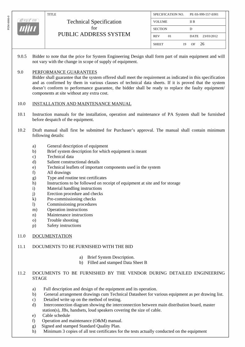
TITLE
Technical Specification for
PUBLIC ADDRESS SYSTEM
SPECIFICATION NO. PE-SS-999-557-E001
VOLUME II B
SECTION D
REV 01 DATE 23/03/2012
SHEET 19 OF 26
PE
M-6
666-
0
9.0.5 Bidder to note that the price for System Engineering Design shall form part of main equipment and will not vary with the change in scope of supply of equipment.
9.0 PERFORMANCE GUARANTEES
Bidder shall guarantee that the system offered shall meet the requirement as indicated in this specification and as confirmed by them in various clauses of technical data sheets. If it is proved that the system doesn’t conform to performance guarantee, the bidder shall be ready to replace the faulty equipment/ components at site without any extra cost.
10.0 INSTALLATION AND MAINTENANCE MANUAL 10.1 Instruction manuals for the installation, operation and maintenance of PA System shall be furnished
before despatch of the equipment. 10.2 Draft manual shall first be submitted for Purchaser’s approval. The manual shall contain minimum
following details: a) General description of equipment b) Brief system description for which equipment is meant c) Technical data d) Salient constructional details e) Technical leaflets of important components used in the system f) All drawings g) Type and routine test certificates h) Instructions to be followed on receipt of equipment at site and for storage i) Material handling instructions j) Erection procedure and checks k) Pre-commissioning checks l) Commissioning procedures m) Operation instructions n) Maintenance instructions o) Trouble shooting p) Safety instructions 11.0 DOCUMENTATION 11.1 DOCUMENTS TO BE FURNISHED WITH THE BID
a) Brief System Description. b) Filled and stamped Data Sheet B
11.2 DOCUMENTS TO BE FURNISHED BY THE VENDOR DURING DETAILED ENGINEERING
STAGE
a) Full description and design of the equipment and its operation. b) General arrangement drawings cum Technical Datasheet for various equipment as per drawing list.
c) Detailed write up on the method of testing. d) Interconnection diagram showing the interconnection between main distribution board, master station(s), JBs, handsets, loud speakers covering the size of cable. e) Cable schedule f) Operation and maintenance (O&M) manual. g) Signed and stamped Standard Quality Plan. h) Minimum 3 copies of all test certificates for the tests actually conducted on the equipment

TITLE
Technical Specification for
PUBLIC ADDRESS SYSTEM
SPECIFICATION NO. PE-SS-999-557-E001
VOLUME II B
SECTION D
REV 01 DATE 23/03/2012
SHEET 20 OF 26
PE
M-6
666-
0

TITLE
Technical Specification for
PUBLIC ADDRESS SYSTEM
SPECIFICATION NO. PE-SS-999-557-E001
VOLUME II B
SECTION D
REV 01 DATE 23/03/2012
SHEET 21 OF 26
PE
M-6
666-
0
Erection and Commissioning

TITLE
Technical Specification for
PUBLIC ADDRESS SYSTEM
SPECIFICATION NO. PE-SS-999-557-E001
VOLUME II B
SECTION D
REV 01 DATE 23/03/2012
SHEET 22 OF 26
PE
M-6
666-
0
CONTENTS 1.0 GENERAL 2.0 CODES AND STANDARDS 3.0 INSTALLATION 3.1 PA SYSTEM EQUIPMENT INSTALLATION 3.2 ITEMS OF SUPPLY FOR CABLING INSTALLATION WORK
3.3 INSTALLATION OF CABLES AND CONDUITS 3.4 ADDITIONAL POINTS OF CONSIDERATION 4.0 QUANTITY MEASUREMENT AND WASTAGE ALLOWANCE 4.1 MEASUREMENT OF QUANTITIES 4.2 CUTTING AND WASTAGE ALLOWANCE 5.0 TESTING 5.1 SITE TESTS 5.2 GENERAL REQUIREMENTS OF SITE TESTING 6.0 PRICES 6.1 GENERAL
6.2 UNIT PRICES OF INSTALLATION WORK

TITLE
Technical Specification for
PUBLIC ADDRESS SYSTEM
SPECIFICATION NO. PE-SS-999-557-E001
VOLUME II B
SECTION D
REV 01 DATE 23/03/2012
SHEET 23 OF 26
PE
M-6
666-
0
1.0 GENERAL The scope of this specification covers handling and storage at site; installation, testing and commissioning of Public Address System for efficient and trouble free operation after installing the same at site.
2.0 CODES AND STANDARDS
The installation shall comply with all currently applicable statutes, regulations and safety codes in the locality where the equipment will be installed. Nothing in this specification shall be construed to relieve the vendor of his responsibility.
3.0 INSTALLATION
The contractor shall carry out total installation work as per the requirements of the specification and instructions of Engineer.
3.1 PA SYSTEM EQUIPMENT INSTALLATION 3.1.1 Installation of PA System equipment shall include erection, connection, grounding, testing and
commissioning of the equipment. Installation activity shall also include provision of all fittings, supports, hangers and other accessories which are not specifically mentioned but are required to complete the installation work.
3.1.2 Equipment shall be brought to the place of work only at the time of erection. Unpacking, handling,
assembling and erection shall be as per the guidelines of installation manual and Field Quality Plan. 3.1.3 Erection shall commence in an area only after the clearance has been obtained from the Engineer. Vendor
shall ensure that all activities, which are liable to damage the equipment in that area, have been completed.
3.1.4 The drilling and welding of building steel work for fixing supports and brackets shall not be done without
the prior approval of Engineer. 3.1.5 Wherever drilling and welding of building steel work for fixing supports and brackets is done, the same
shall be re-painted and restored to the same paint shade as per site requirement at no extra cost to purchaser.
3.2 ITEMS OF SUPPLY FOR CABLING INSTALLATION WORK The supply of below listed items shall be considered to be part of cabling installation work: 3.2.1 Cable glands
Cable glands shall be single or double compression type. Material of glands shall be brass. Nickel plating shall be provided if indicated in Data Sheet A. Rubber components used in the gland shall be of neoprene. Name/ trade name of manufacturer, type no. and applicable range of outer diameter of cable shall be engraved/ printed on the cable gland.
3.2.2 Cable lugs
Cable lugs shall be of tinned copper. Name/ trade name and size shall be engraved/ printed on each cable lug.
3.2.3 Self Locking Clamps
Clamps shall be of nylon material having self-locking feature when the cord is looped. They shall be provided with manual lock release. Clamp cord shall not move in the backward direction once it has been locked, unless the lock release is depressed.
3.2.4 Ferrules
Ferrules shall be required for individual core of cables hence they shall be suitable for the insulated

TITLE
Technical Specification for
PUBLIC ADDRESS SYSTEM
SPECIFICATION NO. PE-SS-999-557-E001
VOLUME II B
SECTION D
REV 01 DATE 23/03/2012
SHEET 24 OF 26
PE
M-6
666-
0
conductor diameter. They shall be of plastic material. Numbering on the ferrules shall be engraved type. Colour of base shall be yellow and that of engraving shall be black. Engrave colouring shall be of durable quality to match the entire life of the plant. Engraving shall be legible from a distance of 600 mm. Ferrules shall be interlocked type such that the interlocked ferrules take the shape of tube with complete ferrule number marked in a straight line.
3.2.5 Tags
For identification, cables shall be provided with cable number tags of durable fibre, aluminium or stainless steel sheets. Cable numbers shall be engraved type in case of aluminium or stainless steel tags, and printed type in case of fibre sheet. Tags shall be of durable quality of size 60mm x 12mm with a tie hole at each end and shall be provided with non-corrosive wire of sufficient strength for tagging.
3.3 INSTALLATION OF CABLES AND CONDUITS 3.3.1 All cables shall be provided with identification tags indicating the cable numbers in accordance with the
cable circuit schedule. Tags shall be fixed at both ends of cables and on both sides of floor/ wall crossings.
3.3.2 All cable entries in the equipment shall be sealed by cable glands. 3.3.3 Power cable terminations shall be carried out in such a manner as to avoid strain on the terminals by
providing suitable clamps near the terminals. 3.3.4 Control cable cores entering the equipment or control panels shall be neatly bunched and strapped with
PVC perforated tapes/ nylon ties and suitably supported to keep them in position at the terminal block. Copper conductor control cables shall be terminated directly into screw type terminals provided in the equipment.
3.3.5 Wherever control cables are to be terminated by means of terminal lugs, the same shall be of tinned
copper compression type. 3.3.6 All spare cores shall be connected to spare terminals wherever possible. If spare terminals are not
available, spare cores shall be neatly dressed and suitably taped at both ends. 3.3.7 Individual cores of control cables shall have ferrules for identification. Ferrule numbers shall be provided
as per the control schemes and other related documents supplied by the purchaser. 3.4 ADDITIONAL POINTS OF CONSIDERATION 3.4.1 The installation work shall be carried out in a neat workman-like manner by skilled, experienced and
competent workmen. 3.4.2 Installation shall be properly coordinated at site with other services and wherever necessary suitable
adjustment shall be made to avoid interference with any part of the building, structures, equipment, utilities and services. Any such adjustment shall be done with the approval of Engineer.
3.4.3 All materials being supplied or consumed during erection by the vendor in the process of erection work
shall be of the best quality and according to the relevant standards. All materials shall be got inspected and approved by the Engineer before the same is used for erection work.
3.4.4 Any work like chipping/ breaking of existing structure like walls, floors, fabrications, etc. shall be done after taking prior approval of Engineer.
3.4.5 Any wrong erection shall be removed & re-erected promptly to comply with the design requirements to
the satisfaction of Engineer. Re-erection shall be done at no extra cost to the purchaser.

TITLE
Technical Specification for
PUBLIC ADDRESS SYSTEM
SPECIFICATION NO. PE-SS-999-557-E001
VOLUME II B
SECTION D
REV 01 DATE 23/03/2012
SHEET 25 OF 26
PE
M-6
666-
0
3.4.6 While testing and commissioning, if the system is observed to be not functioning, it shall be the
responsibility of the contractor to check, rectify and demonstrate that the defect has been removed to the satisfaction of purchaser.
3.4.7 Before energisation of system, physical inspection shall be carried out and all foreign bodies shall be
removed and loose connecting bolts etc. shall be tightened. 4.0 QUANTITY MEASUREMENT AND WASTAGE ALLOWANCE 4.1 MEASUREMENT OF QUANTITIES 4.1.1 For all payment purposes, measurement shall be made on the basis of the execution drawings/ physical
measurements. Physical measurements shall be made by the contractor in the presence of the Engineer. 4.1.2 Wastage allowance shall be kept in consideration while making material appropriation of supplied items. 4.2 CUTTING AND WASTAGE ALLOWANCE
Vendor shall carefully plan the cutting schedule of each cable drum such that wastages are minimised and any resultant short lengths can be used where appropriate route lengths are available.
5.0 TESTING 5.1 Site Tests 5.1.1 After assembly, all major equipment together are to be site tested to establish the workability of the
system at site. 5.1.1.1 Following tests are to be performed at site:
a) Insulation resistance, HV test for cables. b) Rated output power. c) Performance of PAGE and PRIVATE channels for all equipments in the entire Public Address
System. d) Proper functioning of auto-changeover unit. e) Test to ensure that db level of announcement at any station by its own handset shall be lower than
announcement at the same station by any other handset. 5.1.1.2 Bidder to perform all site tests as per the Field Quality Plan. During contract stage bidder to furnish
details of these tests & the standards to which these conform for purchasers approval. 5.2 General Requirements of Site Testing 5.2.2.1 The Owner may ask for any tests at site which in his opinion are necessary to determine that the works
comply with the specification, manufacturer’s instruction or the applicable IS code of installation. The Contractor shall be responsible for conducting the tests and shall bear the cost of such additional tests.
5.2.2.2 The contractor shall have to bring all testing equipment & instruments to carry out the job. All
instruments shall be calibrated to the satisfaction of the Engineer before actual testing and tests shall be conducted by qualified & experienced personnel.
5.2.2.3 All documents/ records regarding test data and all other measured values shall be submitted to Engineer for approval and subsequent record and reference. The results of all tests shall conform to the specification requirements as well as any specific performance data guaranteed during finalisation of contract.

TITLE
Technical Specification for
PUBLIC ADDRESS SYSTEM
SPECIFICATION NO. PE-SS-999-557-E001
VOLUME II B
SECTION D
REV 01 DATE 23/03/2012
SHEET 26 OF 26
PE
M-6
666-
0
6.0 PRICES
6.1 GENERAL
Unit prices listed out in this clause shall be applicable for payment to the contractor for activities covered under this specification. The following shall be kept in consideration while quoting the prices:
6.2 UNIT PRICES OF INSTALLATION WORK
Detailed requirement for all the items are given in the specifications, Data Sheet A and Annexures. a) Unit price of installation shall include transportation of materials from Vendor’s/ Owner’s storage yard
to work site, handling, testing before erection, testing after erection and commissioning of materials including supply and installation of all associated materials (including support materials) and consumables, carrying out of all associated minor civil works and furnishing of all skilled/ unskilled labour, supervisory and commissioning staff.
b) Price of earth connections are to be included in the erection price of equipment as above. c) No separate prices shall be applicable for termination of cables. Cable termination shall include
drilling of gland plates, fixing of glands, ferrules and lugs and connection to the equipment. d) Purchaser reserves the right to delete/ add any of the equipment or services from the bidder’s scope of
work. e) The unit prices quoted shall be for supply and/ or installation as explained in detail in the clauses in
subsequent paragraphs. No other prices shall be applicable for the purpose of payment. f) While quoting the prices for installation, the following shall be considered as part of job:
i. Cable glands and lugs ii. Clamps, ferrules, aluminium/ stainless steel tags as per the project requirements
iii. Fasteners like nuts, bolts, washers, spring washers, rawl plugs, anchoring bolts and lugs etc.
iv. Conduit plugs, gaskets, couplers, and insulated bushings iv. Sealing compounds for wall and floor openings v. Consumables like enamels, cold zinc paint, electrodes for welding etc.
vi. Materials for minor civil works g) The following shall be arranged by the contractor at no extra cost:
i. All unskilled and skilled labour ii. All supervisory and commissioning staff iii. All facilities/ equipment for site fabrication such as cutting, bending and drilling equipment iv. Welding set(s) v. Material handling equipment vi. All special tools and tackles for erection viii. All testing equipment
h) Requirement of Quality Plan and Field Quality Plan shall be considered in the quoted prices. i) E & C spares required shall be part of E & C charges. j) Instruments required fro testing & commissioning shall be arranged by the contractor and shall be
taken back after E & C. k) Fabrication and painting of support structures of various equipments shall be in contractor’s scope.
However structural steel shall be free issue by BHEL.

DATASHEET A
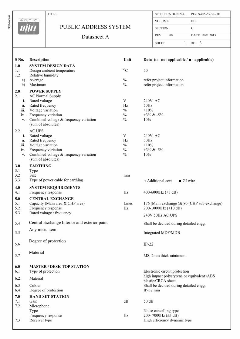
TITLE
PUBLIC ADDRESS SYSTEM
Datasheet A
SPECIFICATION NO. PE-TS-405-557-E-001
VOLUME IIB
SECTION C
REV 00 DATE 19.01.2015
SHEET 1 OF 3
PE
M-6
666-
0
S No.
Description
Unit
Data (□ - not applicable / ■ - applicable)
1.0 SYSTEM DESIGN DATA 1.1 Design ambient temperature OC 50 1.2 Relative humidity
a) Average % refer project information b) Maximum % refer project information
2.0 POWER SUPPLY 2.1 AC Normal Supply
i. Rated voltage V 240V AC ii. Rated frequency Hz 50Hz
iii. Voltage variation % ±10% iv. Frequency variation % +3% & -5% v. Combined voltage & frequency variation % 10%
(sum of absolutes)
2.2 AC UPS i. Rated voltage V 240V AC
ii. Rated frequency Hz 50Hz iii. Voltage variation % ±10% iv. Frequency variation % +3% & -5% v. Combined voltage & frequency variation % 10%
(sum of absolutes)
3.0 EARTHING 3.1 Type 3.2 Size mm 3.3 Type of power cable for earthing □ Additional core ■ GI wire
4.0 SYSTEM REQUIREMENTS 4.1 Frequency response Hz 400-6000Hz (±3 dB)
5.0 CENTRAL EXCHANGE 5.1 Capacity (Main area & CHP area) Lines 176 (Main exchange )& 80 (CHP sub-exchange) 5.2 Frequency response Hz 200-10000Hz (±10 dB) 5.3 Rated voltage / frequency
240V 50Hz AC UPS
5.4 Central Exchange Interior and exterior paint Shall be decided during detailed engg.
5.5 Any misc. item
Integrated MDF/MDB
5.6 Degree of protection
IP-22
5.7 Material
MS, 2mm thick minimum
6.0 MASTER / DESK TOP STATION 6.1 Type of protection Electronic circuit protection
6.2 Material high impact polystyrene or equivalent /ABS plastic/CRCA sheet
6.3 Colour Shall be decided during detailed engg. 6.4 Degree of protection IP-32 min
7.0 HAND SET STATION 7.1 Gain dB 50 dB 7.2 Microphone Type Noise cancelling type Frequency response Hz 200- 7000Hz (±3 dB) 7.3 Receiver type High efficiency dynamic type

TITLE
PUBLIC ADDRESS SYSTEM
Datasheet A
SPECIFICATION NO. PE-TS-405-557-E-001
VOLUME IIB
SECTION C
REV 00 DATE 19.01.2015
SHEET 2 OF 3
PE
M-6
666-
0
S No.
Description
Unit
Data (□ - not applicable / ■ - applicable)
7.4 Enclosure material, thickness
■ Al (3 mm) ■ FRP (4 mm■PVC (3 mm) ■high impact polystyrene or equivalent
7.5 Degree of protection IP-55 for main plant area.IP-65 for CHP area 7.6 Paint shade Shall be decided during detailed engg. 7.7 Type of mounting Wall / column mounting
8.0 AMPLIFIER 8.1 Class Class-B push-pull type 8.2 Frequency response Hz 200 -10000 Hz (±3 dB) 8.3 Total harmonic distribution at 1000 Hz % Not more than 1% 8.4 Signal to noise ratio dB 60dB 8.5 Supply voltage Volt 240 V AC 8.6 Enclosure material, thickness Aluminium, 3 mm 8.7 Degree of protection IP-55 8.8 Paint shade Shall be decided during detailed engg.
9.0 HORN TYPE LOUD SPEAKER 9.1 Power Handling capacity Watts 15 watts (rms) minimum 9.2 Frequency response Hz 500-4500 Hz (±3 dB) 9.3 Sound pressure level at 1k Hz at 1Mtr dB 102 Db (min) 9.4 Bell diameter 10 inch minimum 9.5 Enclosure material 18 SWG Aluminium (Spin) 9.6 Degree of protection IP-55 for main plant area , IP-65 for CHP area 9.7 Paint shade Shall be decided during detailed engg.
10.0 CONE TYPE LOUD SPEAKER 10.1 Power Handling capacity Watts 4 watts (rms) minimum 10.2 Frequency response Hz 200-7000 Hz (±3 dB) 10.3 Sound pressure level at 1k Hz at 1Mtr dB 84 dB (min) 10.4 Enclosure material 16 SWG MS sheet (Spin) 10.5 Degree of protection IP-52 10.6 Paint shade for all areas Shall be decided during detailed engg 10.7 Paint shade for CCR/EER Shall be decided during detailed engg
11.0 JUNCTION BOX(POWER/SIGNAL) 11.1 Degree of protection IP-55 for indoor & IP-65 for outdoor 11.2
Enclosure material & thickness ■ FRP, 4MM
11.3 Paint shade RAL 7305
12.0 POWER DISTRIBUTION BOX 12.1 Capacity 2 inputs( Auto change over switch) & 32 outputs 12.2 Enclosure material 16 SWG MS Sheet 12.3 Degree of protection IP-55 12.4 Paint shade As per manufacturer’s standard practice 12.5 Paint finish Powder coated, textured 12.6 MCB provided ■YES □ No
13.0 Signal Loop Length 13.1 Unit area km 4 13.2 CHP/LHS area km 8 13.3 Common area km 7
14.0 Scope 14.1 Cables Free issue by BHEL 14.2 Conduits Free issue by BHEL

TITLE
PUBLIC ADDRESS SYSTEM
Datasheet A
SPECIFICATION NO. PE-TS-405-557-E-001
VOLUME IIB
SECTION C
REV 00 DATE 19.01.2015
SHEET 3 OF 3
PE
M-6
666-
0
S No.
Description
Unit
Data (□ - not applicable / ■ - applicable)
14.3 Cable trays and support structure BHEL
15.0 Type Tests 15.1 Type tests to be conducted for this contract, despite availability of valid & acceptable test certificates
□ Yes ■No (Type test certificate should be furnished )
15.2 If yes, list of type tests to be conducted 16.0 Special tools & tackles 16.1Special tools & tackles to be quoted for this contract ■ Yes □ No
16.2 If yes, list of Special tools & tackles Bidder to furnish the list

TITLE
3 X 660 MW NORTH KARANPURA STPP
PUBLIC ADDRESS SYSTEM
SPECIFICATION NO. PE-TS-405-557-E-001
VOLUME IIB
SECTION D
REV 0 DATE 19.01.2015
SHEET 1 OF 1
ANNEXURE 6
List of applicable codes & standards 1.0 The equipment covered under this specification shall be designed, constructed and tested in accordance with latest revisions of applicable codes/ standards. 2.0 The equipments furnished under this specification shall conform to the latest revisions of the following standards.
IS10426 PA System amplifiers-recommendations for minimum performance requirements and PA System amplifiers-recommendations for general requirements.
IS1882 PA system-code of practice for out door installations.
IS1881 Indoor amplifying and sound reinforcement system-code of practice for installation.
IS1031 Method of measurements on loudspeaker and loud speakers systems.
IS2382 Recommended mounting dimensions of loud speakers.
IS9302 Characteristics and Methods of Measurement for sound System equipment.
IS616 Code of safety requirement for mains operated electronic and related apparatus.
IS7741(Part-I,II and III) Specification for loudspeaker.
IS9000 Basic environmental testing procedures for electric and electronic items.
IS2147 Degree of protection provided by enclosures for low voltage switchgear and control gear.
IS9537(Part-I and II) IS:1301 IS:1982 IS:732 IS:2667
Specification for conduits for Electrical (Part-I, II) installation/wiring. Code of safety requirement for electric mains operated audio amplifiers Code of practice for outdoor installation of PA system Code of practice of electrical wiring installations (System voltage not exceeding 650 volts) Fittings for rigid steel conduits for electrical wiring
The system shall be adequately protected from signal and power line noise and meet the Surge Withstand Capability (SWC) requirements of ANSI C37.90 A/IEEE standard 472-1989 or equivalent.

DATASHEET C

TITLE
3 X 660 MW NORTH KARANPURA STPP
PUBLIC ADDRESS SYSTEM
Datasheet C
SPECIFICATION NO. PE-TS-405-557-E-001
VOLUME IIB
SECTION D
REV 0 DATE 19.01.2015
SHEET 1 OF 6
PE
M-6
66
6-0
S.NO. DESCRIPTION PARTICULARS UNIT
1.0 SYSTEM DESIGN DATA
1.1 Design ambient temperature : oC
2.0 APPLICABLE STANDARDS
2.1 Whether all standards : [ ] Yes [ ] No
specified in Annexure I of
Data Sheet A followed
3.0 COMPLETE SYSTEM REQUIREMENTS
a) Frequency response : Hz
b) Hum & noise level or :
signal to noise level
4.0 SCOPE OF SYSTEM DESIGN : [ ] Included
ENGINEERING [ ] Excluded
5.0 POWER SUPPLY
5.1 Whether the system suitable : [ ] Yes [ ] No
for operation for power supply
details given in specification
and Data Sheet A.
5.2 Power supply requirement at : kVA
240V AC
6.0 CONSTRUCTIONAL REQUIREMENTS
6.1 AMPLIFIERS : Pre- Line Loud Speaker
(To be furnished Amplifier Amplifier Amplifier
separately for each type
of amplifier)
a) Name of the manufacturer :
b) Type and manufacturer’s :
catalogue no.
c) Power supply details :
d) Full load consumption(VA) :
e) Rated load/ (W/Ohm) :
output impedance
f) Max. ambient conditions :
g) Output voltage (V) :
h) Frequency response (Hz) :
i) Total harmonic (%) :
j) Noise level (db) :
k) Power band width (Hz) :
l) Construction :
m) Controls provided
i. Cont. variable : [ ] Yes [ ] No

TITLE
3 X 660 MW NORTH KARANPURA STPP
PUBLIC ADDRESS SYSTEM
Datasheet C
SPECIFICATION NO. PE-TS-405-557-E-001
VOLUME IIB
SECTION D
REV 0 DATE 19.01.2015
SHEET 2 OF 6
PE
M-6
66
6-0
S.NO. DESCRIPTION PARTICULARS UNIT
volume control
ii. Standby and idle : [ ] Yes [ ] No
time power supply
cut-off arrangement
arrangement
iii. Bass & treble : [ ] Yes [ ] No
control
n) Sensitivity w.r.t. (mV) :
nominal output
o) Output connections :
p) Indications :
6.2 HANDSETS
6.2.1 Master Handset Station(s)
a) Name of the manufacturer :
b) Type and manufacturer’s :
catalogue no.
c) Material :
d) Degree of protection :
e) Surface treatment :
f) Whether all features : [ ] Yes [ ] No
provided on master
handset station as per
specification requirements
g) Type of circuit :
protection
h) Mounting arrangement :
i) Dimensions (L*D*H) : mm
j) Weight : kg
6.2.2 HANDSETS (To be furnished Outdoor/ Indoor
separately for each type) Indoor desk mtd
Wall mtd
a) Name of the manufacturer :
b) Type and manufacturer’s :
catalogue no.
c) Material :
d) Impedance of the : Ohm
transmitter
e) Frequency response of : Hz
the transmitter
f) Impedance of the receiver : Ohm
g) Receiver output : mV
h) Receiver frequency : Hz
response
i) Details of provision for :
noise cancellation features
j) Details of provision for :
directional features
k) Whether all features : [ ] Yes [ ] No
provided on handset

TITLE
3 X 660 MW NORTH KARANPURA STPP
PUBLIC ADDRESS SYSTEM
Datasheet C
SPECIFICATION NO. PE-TS-405-557-E-001
VOLUME IIB
SECTION D
REV 0 DATE 19.01.2015
SHEET 3 OF 6
PE
M-6
66
6-0
S.NO. DESCRIPTION PARTICULARS UNIT
station as per
specification requirements
l) Degree of protection :
m) Surface treatment :
n) Mounting :
o) Dimension with control : mm
box (L*D*H)
p) Weight : kg
6.3 LOUDSPEAKERS (To be furnished Reentrant Cone
separately for each type)
a) Name of the manufacturer :
b) Type and manufacturer’s :
catalogue no.
c) Material :
d) Degree of protection :
e) Surface treatment
i. Exterior surface :
ii. Interior surface :
f) Impedance matching volts : Ohm
(Transformer details)
g) Output power
i. rms : Watt
ii. Peak : Watt
h) Frequency response : Hz
i) Cut-off frequency : Hz
j) Sound level at 1000 Hz :
db/watt mtr. distance
k) Controls provided :
l) Bell diameter : mm
m) Acoustic length : mm
n) Dispersion angle : Deg.
o) Speaker diameter : mm
p) Weight : kg
6.4 MAIN DISTRIBUTION BOX
a) Name of the manufacturer :
b) Type :
c) Construction :
d) Material :
e) Sheet steel thickness : mm
f) Number of ways :
g) Degree of protection :
h) Surface treatment :
i) Dimensions (L*D*H) : mm
6.5 JUNCTION BOX (to be furnished JB-1 JB-2 JB-3
separately for each type)
a) Name of the manufacturer :
b) Type :
c) Construction :
d) Material :
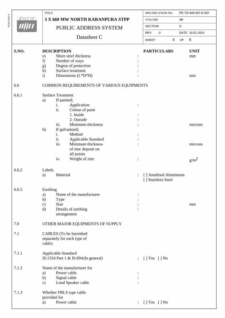
TITLE
3 X 660 MW NORTH KARANPURA STPP
PUBLIC ADDRESS SYSTEM
Datasheet C
SPECIFICATION NO. PE-TS-405-557-E-001
VOLUME IIB
SECTION D
REV 0 DATE 19.01.2015
SHEET 4 OF 6
PE
M-6
66
6-0
S.NO. DESCRIPTION PARTICULARS UNIT
e) Sheet steel thickness : mm
f) Number of ways :
g) Degree of protection :
h) Surface treatment :
i) Dimensions (L*D*H) : mm
6.6 COMMON REQUIREMENTS OF VARIOUS EQUIPMENTS
6.6.1 Surface Treatment
a) If painted;
i. Application :
ii. Colour of paint
1. Inside :
2. Outside :
iii. Minimum thickness : microns
b) If galvanized;
i. Method :
ii. Applicable Standard :
iii. Minimum thickness : microns
of zinc deposit on
all points
iv. Weight of zinc : g/m2
6.6.2 Labels
a) Material : [ ] Anodised Aluminium
[ ] Stainless Steel
6.6.3 Earthing
a) Name of the manufacturer :
b) Type :
c) Size : mm
d) Details of earthing :
arrangement
7.0 OTHER MAJOR EQUIPMENTS OF SUPPLY
7.1 CABLES (To be furnished
separately for each type of
cable)
7.1.1 Applicable Standard
IS:1554 Part 1 & IS:694 (In general) : [ ] Yes [ ] No
7.1.2 Name of the manufacturer for
a) Power cable :
b) Signal cable :
c) Loud Speaker cable :
7.1.3 Whether FRLS type cable
provided for
a) Power cable : [ ] Yes [ ] No
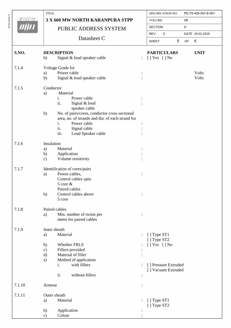
TITLE
3 X 660 MW NORTH KARANPURA STPP
PUBLIC ADDRESS SYSTEM
Datasheet C
SPECIFICATION NO. PE-TS-405-557-E-001
VOLUME IIB
SECTION D
REV 0 DATE 19.01.2015
SHEET 5 OF 6
PE
M-6
66
6-0
S.NO. DESCRIPTION PARTICULARS UNIT
b) Signal & loud speaker cable : [ ] Yes [ ] No
7.1.4 Voltage Grade for
a) Power cable : Volts
b) Signal & loud speaker cable : Volts
7.1.5 Conductor
a) Material
i. Power cable :
ii. Signal & loud :
speaker cable
b) No. of pairs/cores, conductor cross sectional
area, no. of strands and dia. of each strand for
i. Power cable :
ii. Signal cable :
iii. Loud Speaker cable :
7.1.6 Insulation
a) Material :
b) Application :
c) Volume resistivity :
7.1.7 Identification of cores/pairs
a) Power cables, :
Control cables upto
5 core &
Paired cables
b) Control cables above :
5 core
7.1.8 Paired cables
a) Min. number of twists per :
metre for paired cables
7.1.9 Inner sheath
a) Material : [ ] Type ST1
[ ] Type ST2
b) Whether FRLS : [ ] Yes [ ] No
c) Fillers provided :
d) Material of filler :
e) Method of application
i. with fillers : [ ] Pressure Extruded
[ ] Vacuum Extruded
ii. without fillers :
7.1.10 Armour :
7.1.11 Outer sheath
a) Material : [ ] Type ST1
[ ] Type ST2
b) Application :
c) Colour :

TITLE
3 X 660 MW NORTH KARANPURA STPP
PUBLIC ADDRESS SYSTEM
Datasheet C
SPECIFICATION NO. PE-TS-405-557-E-001
VOLUME IIB
SECTION D
REV 0 DATE 19.01.2015
SHEET 6 OF 6
PE
M-6
66
6-0
S.NO. DESCRIPTION PARTICULARS UNIT
7.1.12 Characteristics of FRLS sheath
a) Oxygen index (min.)
b) Temp. index (min.) :
c) Acid gas generation (max.) :
d) Smoke density rating (max.) :
7.1.13 Progressive sequential length marking provided : [ ] Yes [ ] No
on outer sheath
7.2 CONDUITS
a) Name of the manufacturer :
b) Type :
c) Gauge :
d) Size : mm
7.3 ITEMS OF SUPPLY FOR CABLING INSTALLATION WORK
7.3.1 Cable Glands
a) Type : [ ] Single compression
[ ] Double compression
b) Whether Nickel plating done : [ ] Yes [ ] No
8.0 DOCUMENTATION
Whether following documents enclosed :
a) Full description and design of the equipment : [ ] Yes [ ] No
and its operation.
b) Dimensional and mounting details of all : [ ] Yes [ ] No
equipments.
c) General arrangement drawings for handset : [ ] Yes [ ] No
station (all types), loud speakers (all types),
JBs, Auto changeover Box, distribution box etc.
d) Auto changeover switching scheme. : [ ] Yes [ ] No
e) Bill of quantities of cables, JB boxes, : [ ] Yes [ ] No
conduits etc.
f) Detailed write up on the method of testing. : [ ] Yes [ ] No
g) Copies as specified in Section C of all test : [ ] Yes [ ] No
certificates for the tests actually conducted
on the equipment.
h) Final Quality Plan (enclosed in Vol III) : [ ] Yes [ ] No
i) Field quality plan : [ ] Yes [ ] No