technical specification for - nibm motorized... · technical specification of motorised rmu page 2...
TRANSCRIPT

Technical Specification of Motorised RMU Page 1 of 28
TECHNICAL SPECIFICATION
FOR
22 kV and 11 kV
Motorised RING MAIN
UNIT

Technical Specification of Motorised RMU Page 2 of 28
TECHNICAL SPECIFICATION FOR 22 and 11 KV RING MAIN UNIT SWITCHGEAR TABLE OF CONTENTS
1.0 SCOPE 2.0 GENERAL 3.0 STANDARDS 4.0 THE STANDARDS MENTIONED ABOVE ARE AVAILABLE FROM 5.0 CLIMATE CONDITIONS 6.0 RMU OUTDOOR METAL CLAD 7.0 TAKE OFF TERMINAL UNITS FOR FUTURE AUTOMATION 8.0 ISOLATOR (LOAD BREAK TYPE) 9.0 EARTHING OF LOAD BREAK ISOLATORS AND DISTRIBUTION
TRANSFORMER BREAKERS 10.0 DISTRIBUTION TRANSFORMER BREAKER (Vacuum Circuit) 11.0 BUSHINGS 12.0 CABLE BOXES 13.0 CABLE TESTING FACILITY 14.0 VOLTAGE INDICATOR LAMPS AND PHASE COMPARATORS 15.0 EXTENSIBLE 16.0 WIRING AND TERMINALS 17.0 EARTHING 18.0 ACCESSORIES & SPARES 19.0 TESTING OF EQUIPMENT & ACCESSORIES 20.0 TESTS 21.0 INSPECTION 22.0 QUALITY ASSURANCE PLAN 23.0 TRAINING 24.0 SCADA CONNECTIVITY 25.0 DOCUMENTATION and DRAWINGS 26.0 NAME PLATE 27.0 FAULT PASSAGE INDICATOR 28.0 TROPICALISATION 29.0 PROTOTYPE SAMPLES 30.0 MOTORISATION 31.0 METERING 32.0 SCHEDULES 33.0 GUARANTEED TECHNICAL PARTICULARS 34.0 TECHNICAL SPECIFICATION FOR RMU
ANNEXURES 1 TO 6

Technical Specification of Motorised RMU Page 3 of 28
TECHNICAL SPECIFICATION FOR MAINTENANCE FREE 11 KV and 22 kV RING MAIN
UNIT SWITCHGEAR 1.0. SCOPE
Design, Engineering, Manufacture, assembly, Stage testing, inspection and testing before supply and delivery at site, Erection, Installation, testing & Commissioning of Ring Main units outdoor type SF6 filled , with various combinations of load break isolators & breakers. The RMUs should be provided with necessary take off terminal units for future automations and all these units should be shielded in a outdoor metal-body for making them suitable for outdoor use. The insulation/dielectric media inside the stainless steel welded tank should be SF6 gas. The RMUS should be of extensible type on both sides with provision of attaching/connecting with SNAP FIT arrangement W/o External Busbars additional load break switches and circuit breakers in future wherever required.
1.1 This Specification provides for design, manufacture, inspection and testing before despatch, packing and delivery F.O.R.(Destination) of SF6 insulated RMUs with necessary take off terminal units for future automations, other accessories and auxiliaries equipments and mandatory spares, described herein and required for their satisfactory operation.
1.2. The objective of the RMUs is for extremely small construction width, compact, maintenance free, independent of climate, easy installation, operational reliability, Safe and easy to operate, minimum construction cost, minimum site work and minimum space requirement.
1.3. The RMUs shall conform in all respects to high standards Of Engineering design, workmanship and latest revisions of relevant standards at the time of offer.
1.4. The type of the 11 KV and 22 kV circuit breaker shall be VCB and insulating medium for load break isolators, Earth switch, 11 KV and 22 kV Buses and other associated equipments should be SF6 gas.
.
2.1 GENERAL The Ring Main Unit shall be installed at 11 KV and 22 kV junction points to have
continuous supply by isolating faulty sections. The RMU shall be extensible on both sides and consists of the following combinations of load break switches and Circuit

Technical Specification of Motorised RMU Page 4 of 28
breakers for a nominal voltage of 12 KV for 11 kV RMU and 24 kV for 22 kV RMU using SF6 gas as insulating and Vacuum as arc quenching medium.
The RMU and combination shall be tropicalised and outdoor metal enclosed type. The RMU metal parts shall be of high thickness, high tensile steel which must be grit/short blasted, thermally sprayed with Zinc alloy, phosphate or should follow the 7 tank pre-treatment process and be subsequently painted with polyurethane based powder paint. The overall paint layer thickness shall be not less than 80 microns.
Relevant IE rules for clearances, safety and operation inside the enclosure shall be applicable. The enclosure shall be IP54 and type tested from recognized laboratories by National Accreditation Board of Laboratories (NABL).
All live parts except for the cable connections in the cable compartments shall be insulated with SF6 gas. The SF6 gas tank shall be made of TIG welded stainless steel, to have the best weld quality. The gas cubicle shall be metal enclosed with stainless steel of minimum 2 mm thickness and should be provided with a pressure relief arrangement away from operator. The gas tank shall be of completely welded construction. The connection of different welded sections of gas tank by gasket and bolts, to form a RMU chamber is not acceptable. Both the load break switches and the tee off circuit breaker shall be suitable for motorization in future. The cable box of isolators and circuit breakers both should be of front access type. The side and rear access cable box are not preferred as they require greater space for cable connection and maintenance at site. Any accidental over pressure inside the sealed chamber shall be limited by the opening of a pressure-limiting device in the rear-bottom part of the enclosure. Gas will be release to the rear of the switchboard away from the operator and should be directed towards the bottom, into the trench to ensure safety of the operating personnel and the pedestrians / civilians. All the manual operations should be carried out on the front of the switchboard.
The Entire units of RMU shall be enclosed in a single compact metal clad, outdoor
enclosure suitable for all weather conditions. The switchgear/steel gas tank shall be filled with SF6 as per IEC/IS Standards relative pressure to ensure the insulation and breaking functions. The steel gas tank must be sealed for life and shall meet the “Sealed pressure system” criteria in accordance with the IEC 298 standard. The RMU must be a system for which no handling of gas is required throughout the 20 years of service life.
The RMU shall have a design such that in the event of an internal arc fault, the operator shall be safe. This should be in accordance with IEC 298 and relevant Test certificates shall be submitted with the Tender. The RMU shall be tested for an internal arc rating of 21 kA for 1 Sec. Suitable temperature rise test on the RMU shall be carried out & test reports shall be submitted with tender for technical bid evaluation.
Each switchboard shall be identified by an appropriately sized label, which clearly indicates the functional units and their electrical characteristics.

Technical Specification of Motorised RMU Page 5 of 28
The switchgear and switchboard shall be designed so that the position of the different devices is visible to the operator on the front of the switchboard and operations are visible as well.
The entire system shall be totally encapsulated. There shall be no access to exposed conductors. In accordance with the standards in effect, the switchboards shall be designed so as to prevent access to all live parts during operation without the use of tools.
The entire 11 KV and 22 kV RMU are insulated by inert gas (SF6) suitable for operating voltage up to 12 KV and 24 kV respectively. The 11 KV and 22 kV circuit breakers must be VCB breaker. It is necessary to fit an absorption material in the tank to absorb the moisture from the SF6 gas. The SF6 insulating medium shall be constantly monitored via a temperature compensating gas pressure indicator offering a indication at different temperature ranges, like -25, 0, 20, 40, 60 deg centigrade, having distinctive RED and GREEN zones for safe operation.
All the RMUs must be routine tested for the following at factory in India:-
• Micro-ohm test for the assembly inside the tank. • Circuit breaker analyzer test so as to ensure the simultaneous closing of all poles
for VCB. • SF6 gas leak test. • Partial Discharge test on the complete gas tank so as to be assure of the proper
insulation level and high product life. • High voltage withstand. • Secondary test to ensure the proper functioning of the live line indicators, fault
passage indicators and relays.
Sulphur Hex fluoride Gas(SF6 GAS) The SF6 gas shall comply with IEC 376,376A,and 376B and shall be suitable in all
respects for use in 11 KV and 22 kV RMUs under the operating conditions. The SF6 shall be tested for purity, dew point air hydrolysable fluorides and water content as per IEC 376,376A and 376B and test certificate shall be furnished to the owner indicating all the tests as per IEC 376 for each Lot of SF6 Gas.
3.0 STANDARDS
Unless otherwise specified elsewhere in this Specification, the RMU, Switchboard (Switchgear), Load break isolators, Instrument Transformers and other associated accessories shall conform to the latest revisions and amendments there of to the following standards.
1) IEC 60 298/IEC 62 271-200/IS 12729:1988 - General requirement for Metal Enclosed Switchgear
2) IEC60129/IEC62271-102/IS 9921 - Alternating current disconnector’s (Load break isolators) and earthing switch
3) IEC 62 271-100/IEC 60 056/IS 13118:1991 - Specification for alternating IEC 62 271-200 current circuit breakers.

Technical Specification of Motorised RMU Page 6 of 28
4) IEC 62 271-1/IEC 60694 - Panel design, SF6/Vacuum Circuit Breakers
5) IEC 60044-1/IEC 60185/IS 2705:1992 - Current Transformer
7) IEC 60265/IS 9920:1981 - High voltage switches.
8) IEC 376 - Filling of SF6 gas in RMU.
9) IEC 60273/IS :2099 - Dimension of Indoor & Outdoor post insulators
with voltage > 1000 Volts.
10)IEC 60529/IS 13947(Part-1) - Degree of protection provided by
enclosures for low voltage switchgear and
control gear.
11) Indian Electricity Rules/Bills
Equipment meeting with the requirements of any other authoritative standards, which ensures equal or better quality than the standard mentioned above shall also be acceptable. If the equipments, offered by the Bidder conform to other standards, salient points of difference between the standards adopted and the specific standards shall be clearly brought out in relevant schedule. In case of any difference between provisions of these standards and provisions of this specification, the provisions contained in this specification shall prevail. One copy of such standards with authentic English Translations shall be furnished along with the offer.(Hard copy)
4.0. THE STANDARDS MENTIONED ABOVE ARE AVAILABLE FROM:
REFERENCE/ NAME AND ADDRESS FROM WHICH THE ABBREVIATION STANDARDS ARE AVAILABLE
IEC INTERNATIONAL ELECTRO-TECHNICAL
COMMISSION,
BUREAU CENTRAL DE LA COMMISSION, ELECTRO TECHNIQUE INTERNATIONAL, 1, RUE DE VEREMBE, GENEVA, SWITZERLAND.
ISO INTERNATIONAL STANDARD ORGANISATION
SPECIFIC REQUIREMENTS IN RMU:-
The RMUs going to be installed in the field network , will be hooked with SCADA Through RTUs and hence , RMUs used shall be compatible with scada

Technical Specification of Motorised RMU Page 7 of 28
5.0. CLIMATE CONDITIONS The climatic conditions under which the equipment should operate satisfactory
are as under:
Maximum ambient air temperature : 45 deg. C
Minimum ambient air temperature : 10 deg.C
Maximum daily average ambient air temperature : 40 C
Maximum humidity : 80%
Altitude above M.S.L. (maximum) : 1000 metres
Average annual rainfall(mm) : 925
Max. wind pressure(Kg/sq.m) : 200
Seismic level(Horizontal accn.) : 0.3 g
Iso-ceraunic level(Days per Year) : 50
Average thunder storm days per annum : 50
6.0. RMU OUTDOOR METAL CLAD ENCLOSURE.
The RMU enclosure must be a metallic, it shall follows an industrialized process of manufacturing. The RMU and combination shall be tropicalized and outdoor metal enclosed type. The RMU metal parts shall be of high thickness, high tensile steel which must be grit/short blasted, thermally sprayed with Zinc alloy, phosphate or should follow the 7 tank pre-treatment process and be subsequently painted with polyurethane based powder paint. The overall paint layer thickness shall be not less than 80 microns. The rating of enclosure shall be suitable for operation on three phase, three wire, 11 KV and 22 kV, 50 cycles, A.C. System with short-time current rating of 20KA for 3 seconds with RMU Panels.
The enclosure should have two access doors one for the operation and relay monitoring and other for the cable access. Both the doors should have the locking facility.
7.0. TAKE OFF TERMINAL UNITS FOR FUTURE AUTOMATION :
The RMU should be provided with necessary take off terminal units for future automations, located in the front recesses / LV cubical of the RMU.
8.0. ISOLATORS (LOAD BREAK TYPE)
The load break isolators for Incoming and Outgoing supply must be provided. These should be fully insulated by SF6 gas. The load break isolators shall consist of 630 Amp fault making/load breaking spring assisted ring switches, each with integral fault making earth switches. The switch shall be naturally interlocked to prevent the the main and earth switch being switched ‘ON’ at the same time. The selection of the main and earth switch is made by a lever on the facia, which is allowed to move only if the main or earth switch is in the off position. The load break isolators should have the facility for future remote operation. Each load break switch shall be of the triple pole,

Technical Specification of Motorised RMU Page 8 of 28
simultaneously operated, non automatic type with quick break contacts and with integral earthing arrangement.
The isolating distance between the OFF and the ON position in the isolator
should be more than 80mm, so as to have enough isolating distance for ensuring safety during DC injection for Cable testing.
9.0 EARTHING OF ISOLATORS AND DISTRIBUTION TRANSFORMER BREAKERS
(EARTH SWITCH) Necessary arrangements are provided at Load break isolators / Distribution
Transformer Breaker for selecting Earth position. Mechanical interlocking systems shall prevent the RMU function from being operated from the ‘ON’ to ‘Earth’ on position without going through the ‘OFF’ position.
10.0 DISTRIBUTION TRANSFORMER BREAKER (VACUUM)
The VCB breaker for the controlling of DT must be provided inside welded
stainless steel SF6 gas tank with the outdoor metal clad enclosure. The VCB circuit breaker must be a spring assisted three positions with integral
fault making earth switch. The selection of the main/earth switch lever on the facia, which is allowed to move only if the main or earth switches is in the off position. The manual operation of the circuit breaker shall not have an effect on the trip spring. This should only be discharged under a fault (electrical) trip; the following manual reset operation should recharge the trip spring and reset the circuit breaker mechanism in the main off position.
The circuit breaker shall be fitted with a mechanical flag, which shall operate in the event of a fault (electrical) trip occurring. The ‘tripped’ flag should be an unambiguous
colour differing from any other flag or mimic.Both the circuit breaker and ring switches are operated by the same unidirectional handle. The protection on the circuit breaker shall comprise of the following components:-
- 3 class X protection CT’s, - a low burden trip coil and - a self powered (No external DC or AC source required) IDMT protection relays (Numeric/Micro processor based) 3 x over current and earth fault element shall be Definite Time type relay . The protection system should be suitable for protecting transformers of rated power from 250 KVA on wards. The relay should be housed within a pilot cable box accessible.
11.0 BUSHINGS
The units are fitted with the standardized bushings that comply with IEC standards. All the bushings are the same height from the ground and are protected by a cable cover.
12.0 CABLE BOXES
All the cable boxes shall be air insulated suitable for dry type cable terminations and should have front access only. Side and rear cable entry / access should be avoided,

Technical Specification of Motorised RMU Page 9 of 28
so not to have extra space at site for cable connection and cable testing. The cable boxes at each of the two ring switches should be suitable for accepting HV cables of sizes 3c x 185/3c x 300 sq.mm and circuit breaker cable suitable up to 3c x 185 sq.mm. The cable boxes for an isolator in it’s standard design should have sufficient space for connecting two cables per phase. Necessary Right angle Boot should be supplied to the cable terminations .The type of the Right angle Boot should be cold applied insulating Boot.
13.0 CABLE TESTING FACILITY It shall be possible to test the cable after opening the cable boxes. The cable
boxes should open only after operation of the earth switch. Thus ensuring the earthing of the cables prior to performing the cable testing with DC injection.
14.0. VOLTAGE INDICATOR LAMPS AND PHASE COMPARATORS
The RMU shall be equipped with a voltage indication to indicate whether or not there is voltage on the cable. There should be a facility to check the synchronization of phases with the use of external device. It shall be possible for the each of the function of the RMU to be equipped with a permanent voltage indication as per IEC 601958 to indicate whether or not there is voltage on the cables.
15.0. EXTENSIBLE
Each combination of RMU shall have the provision for extension by load break isolators / breakers in future, with suitable accessories and necessary Bus Bar. The equipment shall be well designed to avoid any kind of extension / trunking chamber for connecting and housing extensible Busbars. Extensible isolators and circuit breakers shall be individually housed in separate SF6 gas enclosures. Multiple devices inside single gas tank / enclosure will not be acceptable. In case of extensible circuit breakers, the Breaker should be capable of necessary short circuit operations as per IEC at 20 KA, and the Breaker should have a rated current carrying capacity of 200 A.
16.0. WIRING & TERMINALS:
The wiring should be of high standard and should be able to withstand the tropical weather conditions. All the wiring and terminals (including take off terminals for future automation, DC, Control wiring), Spare terminals shall be provided by the contractor. The wiring cable must be standard single-core non-sheathed, Core marking (ferrules), stripped with non-notching tools and fitted with end sleeves, marked in accordance with the circuit diagram with printed adhesive marking strips.
The wiring should be of high standard and should be able to withstand the tropical weather conditions. All wiring shall be provided with single core multistrand copper conductor wires with P.V.C insulation.
The wiring shall be carried out using multi-strand copper conductor super flexible PVC insulated wires of 650/1100V Grade for AC Power, DC Control and CT circuits. Suitable colored wires shall be used for phase identification and interlocking type ferrules shall be provided at both ends of the wires for wire identification. Terminal should be suitably protected to eliminate sulphating. Connections and terminal should be able to withstand vibrations. The terminal blocks should be stud

Technical Specification of Motorised RMU Page 10 of 28
type for controls and disconnecting link type terminals for CT leads with suitable spring washer and lock nuts.
Flexible wires shall be used for wiring of devices on moving parts such as swinging Panels (Switch Gear) or panel doors. Panel wiring shall be securely supported, neatly arranged readily accessible and connected to equipment terminals, terminal blocks and wiring gutters. The cables shall be uniformly bunched and tied by means of PVC belts and carried in a PVC carrying trough.
The position of PVC carrying trough and wires should not give any hindrance for fixing or removing relay casing, switches etc., Wire termination shall be made with solder less crimping type of tinned copper lugs. Core identification plastic ferrules marked to correspond with panel wiring diagram shall be fitted with both ends of each wire. Ferrules shall fit tightly on the wire when disconnected. The wire number shown on the wiring shall be in accordance with the IS.375.
All wires directly connected to trip circuits of breaker or devices shall be distinguished by addition of a red color unlettered ferrule.
Inter-connections to adjacent Panels (Switch Gear) shall be brought out to a separate set of Terminal blocks located near the slots or holes to be provided at the top portion of the panel. Arrangements shall be made for easy connections to adjacent Panels (Switch Gear) at site and wires for this purpose shall be provided and bunched inside the panel. The bus wire shall run at the top of the panel. Terminal block with isolating links should be provided for bus wire. At least 10% of total terminals shall be provided as spare for further connections. Wiring shall be done for all the contacts available in the relay and other equipment and brought out to the terminal blocks for spare contacts. Color code for wiring is preferable in the following colours.
Voltage supply Red, Yellow, Blue for phase and Black for Neutral CT circuits similar to the above DC circuits Grey for both positive and negative 250V AC circuits Black for both phase and neutral Earthing Green
The wiring shall be in accordance to the wiring diagram for proper functioning of the connected equipment. Terminal blocks shall not be less than 650V grade and shall be piece-molded type with insulation barriers. The terminal shall hold the wires in the tight position by bolts and nuts with lock washers. The terminal blocks shall be arranged in vertical formation at an inclined angle with sufficient space between terminal blocks for easy wiring. The terminals are to be marked with the terminal number in accordance with the circuit diagram and terminal diagram. The terminals should not have any function designation and are of the tension spring and plug-in type.
17.0. EARTHING
The RMU outdoor metal clad, Switch Gear, Load break isolators, Vacuum circuit breakers shall be equipped with an earth bus securely fixed along the base of the RMU. The size of the earth bus shall be made of IEC/IS standards with tinned copper flat for RMU and M.S.Flat for Distribution Transformer, earth spike and neutral earthing. Necessary terminal clamps and connectors shall be included in the scope of supply.
Technical Specification of Motorised RMU Page 11 of 28
All metal parts of the switchgear which do not belong to main circuit and which can collect electric charges causing dangerous effect shall be connected to the earthing conductor made of copper having CS area of minimum 75 mm″. Each end of conductor shall be terminated by M12/equivalent quality and type of terminal for connection to earth system installation. Earth conductor location shall not obstruct access to cable terminations. The following items are to be connected to the main earth conductor by rigid or copper conductors having a minimum cross section of 75 mm″ (a) earthing switches (b) Cable sheath or screen (c) capacitors used in voltage control devices, if any.
The metallic cases of the relays, instruments and other panel mounted Equipment shall be connected to the earth bus by independent copper wires of size shall be made of IEC/IS standards. The colour code of earthing wire shall be green. Earthing wires shall be connected on the terminals with suitable clamp connectors and soldering shall not be permitted.
18.0 ACCESSORIES & SPARES:
The following spares and accessories shall be supplied along with the main equipments at free of costs. This shall not be included in the price schedule. 1) Charging lever for operating load break isolators & circuit breaker of each RMU. 2) The pressure gauges indications – 1 numbers
Provision shall be made for padlocking the load break switches/ Circuit breaker, and the earthing switches in either open or closed position with lock & master key.
19.0.TESTING OF EQUIPMENT & ACCESSORIES:
Provision for testing CTs, Relays, Breakers and Cables shall be made available. Procedure and schedule for Periodical & Annual testings of equipments, relays, etc. shall be provided by the supplier.
20.0. TESTS:
20.1.TYPE TEST The Tenderers should, along with the tender documents, submit copies of all
Type test certificate of their make in full shape as confirming to relevant ISS/IEC of latest issue obtained from a International/National Govt. Lab/Recognized laboratory.
The above type test certificates should accompany the drawings for the materials duly signed by the institution who has type test certificate. The details of type test certificate as per Schedule F.
20.2 ACCEPTANCE AND ROUTINE TESTS
All acceptance and routine tests as stipulated in the latest IEC- shall be carried out by the supplier in the presence of NIBM representative. The supplier shall give at
least 7 days advance intimation to the NIBM to enable them to depute their representative for witnessing the tests. The partial discharge shall be carried out as
routine test on each and every completely assembled RMU gas tank and not on a sample basis. As this test checks and guarantees for the high insulation level and thus
the complete life of switchgear.

Technical Specification of Motorised RMU Page 12 of 28
20.3. ADDITIONAL TESTS The NIBM reserves the right for carrying out any other tests of a reasonable
nature at the works of the supplier/laboratory or at any other recognized laboratory/research institute in addition to the above mentioned type, acceptance and routine tests at the cost of the NIBM to satisfy that the material complies with the intent of this specification.
20.4. PRE-COMMISSIONING TESTS
All the pre-commissioning tests will be carried out in the presence of the NIBM engineer and necessary drawing manual and periodical test tools shall be arranged to be supplied. During the above tests the contractor’s representative should be present till the RMUs are put in to service. 21.0. INSPECTION:
The inspection may be carried out by the NIBM at any stage of manufacture. The supplier shall grant free access to NIBM representative at a reasonable time when
the work is in progress. Inspection and acceptance of any equipment under this specification by the NIBM shall not relieve the supplier of his obligation of furnishing
equipment in accordance with the specification and shall not prevent subsequent rejection if the equipment is found to be defective.
The supplier shall keep the NIBM informed in advance, about the manufacturing programme so that arrangement can be made for inspection. The NIBM reserves the
right to insist for witnessing the acceptance/routine testing of the bought out items. The NIBM has rights to inspect the supplier’s premises for each and every consignment for
type & routine test. No material shall be dispatched from its point of manufacture unless the material has been satisfactorily inspected and tested / unless the same is waived by the NIBM in writing.
22.1. QUALITY ASSURANCE PLAN: The bidder shall invariably furnish following information along with his offer / in
case of event of order. (i) Statement giving list of important raw materials including but not
limited to (a) Contact material (b) Insulation (c) Sealing material (d) Contactor, limit switches, etc. in control cabinet.
Name of sub-suppliers for the raw materials, list of standards according to which the raw materials are tested, list of test normally carried out on raw materials in
presence of Bidder’s representative, copies of test certificates.
(ii) Information and copies of test certificates as in (i) above in respect of bought out accessories.

Technical Specification of Motorised RMU Page 13 of 28
iii) List of areas in manufacturing process, where stage inspections are normally carried out for quality control and details of such tests and inspections.
iv) Special features provided in the equipment to make it maintenance free.
v) List of testing equipment available with the Bidder for final testing of R mus and associated combinations vis-à-vis, the type, special, acceptance and routine tests specified in the relevant standards. These limitations shall be very clearly brought out in the relevant schedule i.e. schedule of deviations from specified test requirements. The supplier shall, within 15days from the date of receipt of Purchase Order submit following information to the NIBM.
i) List of raw materials as well bought out accessories and the names of sub-
suppliers selected from those furnished along with offer. ii) Necessary test certificates of the raw material and bought out accessories.
iii) Quality Assurance Plan (QAP) with hold points for NIBM inspection. The quality assurance plan and hold points shall be discussed between the NIBM
and supplier before the QAP is finalised.
The supplier shall submit the routine test certificates of bought out items and raw material, at the time of routine testing of the fully assembled breaker.
23.0 TRAINING:
The supplier shall give rigorous training to the engineers & staff at the site for 2 days in attending trouble shooting and maintenance .
24.1. SCADA CONNECTIVITY: - SPECIFIC REQUIREMENT FOR SCADA CONNECTIVITY
A) Following DMS requirement shall be fulfilled: 1. FPI shall be provided per isolator 2. DC control supply system should be 24VDC. 3. Battery charger to cater load of minimum 10 motorised operation cycles (CLOSE-
OPEN) in absence of battery. 4. Battery to cater load of minimum 10 motorised operation cycles (CLOSE-OPEN) in
absence of battery charger. The battery backup should be minimum of 2Hrs 5. Availability of MCB's for battery charger supply, RMU Motor supply & FRTU supply
(Minimum 2 Amp circuit for future use of FRTU). 6. Individual control circuit of isolator/CB/BC to have point of isolation/protection. 7. Individual motor circuit of isolator/CB/BC to have point of isolation/protection. 8. RMU shall have minimum protection of IP54 with gland plate & knock outs. Provision
for control cable entry should preferably be from Right/ Left top through LV cable box & shall be independent of HV isolator/CB/BC status. It should be vermin proof.
9. Control cable gland plate shall be independent of power cable gland plate. 10. A point of earthing for control cables shall be electrically isolated from power cable
earthing. 11. Ambient temperature of 50 degree C max. Allowable temperature rise of battery &
battery charger above ambient 40 degree C

Technical Specification of Motorised RMU Page 14 of 28
12. Local / Remote switch shall be provided on all the isolator & breaker panels for selection of controls
13. CT & PT terminals for all the circuit breakers only.
B) Following is the list of I/O requirements for RMU modules. Please note that all DI & DO should be potential free contacts.
a) List of potential free contacts for Isolator (Terminals shall be provided):
Digital Indications 1. Isolator ON 2. Isolator OFF 3. Isolator Earth switch Status (ON/OFF) 4. FPI Operated 5. LOCAL/REMOTE switch position
List of commands
1. Isolator Close 2. Isolator Open 3. FPI reset
b) List of potential free contacts for Circuit Breaker / Bus coupler (Terminals shall be provided):
Digital Indications
1. Circuit Breaker ON 2. Circuit Breaker OFF 3. Auto trip 4. LOCAL/REMOTE switch position
List of commands
1. CB Close 2. CB Open
C) Requirement for Multifunction Meters (MFMs):
Terminals shall be provided for CT and PT connections. Space may be provided for MFM mounting inside control panel.
D) List of potential free signals for AUXILIARY:
Digital Indications 1. RMU Battery charger fail 2. Battery Low indication 2. SF6 low

Technical Specification of Motorised RMU Page 15 of 28
25.0 DOCUMENTATION and DRAWINGS All drawings shall conform to relevant International Standards Organization (ISO)
Specification. All drawings shall be in ink and suitable for microfilming. The tenderer shall submit along with his tender dimensional general
arrangement drawings of the equipments, illustrative and descriptive literature in triplicate for various items in the RMUs which are all essentially required for future automation.
i) Schematic diagram of the RMU panel ii) Instruction manuals iii) Catalogues of spares recommended with drawing to indicate each items of spares iv) List of spares and special tools recommended by the supplier. v) Copies of Type Test Certificates as per latest IS/IEC. vi) Drawings of equipments, relays, control wiring circuit, etc. vii) Foundation drawings of RMU and D.T.Structure. viii) Dimensional drawings of each material used for item Vii. ix) Actual single line diagram of RMU/RMUs with or without Extra combinations shall be
made displayed on the front portion of the RMU so as to carry out the operations easily.
The following should be supplied to each consignee circle along with the initial supply of the equipments ordered.
2 copies of printed and bound volumes of operation, maintenance and erection manuals in English along with the copies of approved drawings and type test reports etc.
26.0. NAME PLATE: Each RMU and its associated equipments shall be provided with a nameplate
legible and indelibly marked with at least the following information. (a) Name of manufacturer (b) Type, design and serial number (c) Rated voltage and current (d) Rated frequency (e) Rated symmetrical breaking capacity (f) Rated making capacity (g) Rated short time current and its duration (h) Purchase Order number and date (i) Month and Year of suppl (j) Rated lighting impulse withstand voltage (k) Feeder name(Incoming and Out going),DTs Structure name,11000Volts
Dangers etc.
NOTE: i) The word rated need not appear on the name plate. Recognized abbreviations may be used to express the above particulars.

Technical Specification of Motorised RMU Page 16 of 28
ii)Whether the circuit breaker is fitted with closing/tripping devices necessitating an auxiliary supply shall be stated either on the circuit breaker name plate or any other acceptable position.
27.0. FAULT PASSAGE INDICATORS (FPI): These shall facilitate quick detection of faulty section of line. The fault
indication may be on the basis of monitoring fault current flow through the device. The unit should be self-contained requiring no auxiliary power supply. The FPI shall be integral part of RMU. The FPI shall have LCD/LED display, automatic reset facility.The sensors to be bushing mounted. FPI Shall be provided per Isolator
28.0. TROPICALISATION
Due regard should be given to the climatic conditions under which the equipment is to work. Ambient temperature normally vary between 20 °C and 32 °C, although direct sun temperature may reach 50 °C. The climate is humid and rapid variations occur, relative humidity between 60% and 90% being frequently recorded, but these values generally correspond to the lower ambient temperatures. The equipment should also be designed to prevent ingrees of vermin, accidental contact with live parts and to minimize the ingress of dust and dirt. The use of materials which may be liable to attack by termites and other insects should be avoided.
29. PROTOTYPE SAMPLE:
The successful bidders should manufacture 3 Nos. of prototype RMUs as per the specification and keep ready at their works for the purpose of sample inspection and testing. The MSEDCL at their option may sent a team of Engineers to the works. Prior intimation of this inspection may not be given to the Bidder.
30. Motorisation : All the functions within the RMU i.e Isolators / Breakers should be fitted with motor mechanism and closing coil making it suitable to make it ON from remote.
Control Supply and Auxillaries : Following Auxillaries has to considered
(i) Shunt trip coil – 24VDC for Isolators and Breakers (ii) Closing Coil – 24VDC (iii) Motor Mechanism – 24VDC (iv) 6NO+6NC – Potential free auxillary contacts for breakers / isolator (v) Auxillary supply should be – 24VDC (vi) Battery/ Battery charger with battery back up of atleast 1hours (Vii) Local / Remote switch for breaker and Isolators
31 Metering: Seperate Metering Module consisting of bus connected PTs And
metering CTs to be provided for VCB function along with Provision of installing Multifuction meter to be provided. The PTs and CTs provided shall made up of epoxy cast resin with an Accuracy class of 0.5. The CT ratio shall be as per transformer Rating. The metering is required only in breaker functions.

Technical Specification of Motorised RMU Page 17 of 28
32. SCHEDULES:
32.1 The tenderer shall fill-in the following schedules which is part and parcel of the tender specification and offer. If the schedules are not submitted duly filled-in with the offer, the offer shall be liable for rejection.
Schedule 'A'(Annexures I to 6) ... Guaranteed and technical particulars. Schedule 'B' ... Schedule of Tenderer's experience.
32.2 Any additional information may be furnished separately by the tenderer, if felt
necessary by him.
33.0 GUARANTEED TECHNICAL PARTICULARS 33.1 The bidder should fill up the details in schedule A – ‘Guaranteed Technical Particulars’ and the statement such as “as per drawing enclosed”, “as per MSEDCL requirement”, “as per IS”, “as per specification” etc. shall be considered as details
not furnished and such offers will be rejected.

Technical Specification of Motorised RMU Page 18 of 28
34.0. TECHNICAL SPECIFICATION FOR RMU A) 11 kV RMU I. 11KV Bus Bar
Current Carrying Capacity : 630 Amps. Short time rating current for 3 secs. : 20 KA Insulation of bus bar : SF6 Bus bar connections : Anti-oxide grease
II. Parameters for Switch Gear of DT and load break isolators Type : Metal enclosed No of Phases 3 No. of poles 3 Rated voltage :12 KV Operating voltage :11 KV(+10% to –20%) Rated lightning impulse withstand voltage :75 KV Rated power frequency withstand voltage :28 KV Insulating gas :SF6 Rated filling level for insulation :As Per IEC. Max.permissible site altitude at the above gas pressures :≤1000m (The operating pressure has to be adjusted for greater altitudes)
Isolating distance between ON and OFF position in isolator :80 mm (min). Rated short time current :20 KA. Rated short time :3s Rated peak withstand current :50 KA. No of operations in Short circuit :15Nos (minimum)
Operating mechanism: Circuit breaker with spring assisted anti reflex
mechanism. Rated current (Bus) :630 A Rated current (breaker) :200 A(Depending on
Transformer Rating) Circuit Breaker interrupter :SF6/VCB Rated frequency : 50 Hz Rated operating sequence :O-3min- CO
Number of mechanical/Remote operations for earthing As per IEC & Ring switches & Number of mechanical/ 60298 remote operations for circuit breakers

Technical Specification of Motorised RMU Page 19 of 28
B) 22 kV RMU I. 22 KV Bus Bar
Current Carrying Capacity : 630 Amps. Short time rating current for 3 secs. : 20 KA Insulation of bus bar : SF6 Bus bar connections : Anti-oxide grease
II. Parameters for Switch Gear of DT and load break isolators Type : Metal enclosed No of Phases 3 No. of poles 3 Rated voltage :24 KV Operating voltage :22 KV(+10% to –20%) Rated lightning impulse withstand voltage :125 KV Peak Rated power frequency withstand voltage :50 KV Insulating gas :SF6 Rated filling level for insulation :As Per IEC. Max.permissible site altitude at the above gas pressures :≤1000m (The operating pressure has to be adjusted for greater altitudes)
Isolating distance between ON and OFF position in isolator :80 mm (min). Rated short time current :20 KA. Rated short time :3s Rated peak withstand current :50 KA. No of operations in Short circuit :15Nos (minimum)
Operating mechanism: Circuit breaker with spring assisted anti reflex
mechanism. Rated current (Bus) :630 A Rated current (breaker) :200A(Depending on Transformer
Rating) Circuit Breaker interrupter :SF6/VCB Rated frequency : 50 Hz Rated operating sequence :O-3min- CO
Number of mechanical/Remote operations for earthing As per IEC & Ring switches & Number of mechanical/ 60298 remote operations for circuit breakers

Technical Specification of Motorised RMU Page 20 of 28
III. PRINCIPAL FEATURES
Sl No
DESCRIPTION DT breaker
1 Circuit label Yes 2 Mimic diagram Yes 3 Supply voltage indication Yes 4 Current Transformer Yes 5 Self Powered based Microprocessor based
IDMT Relay (3OL)/EL Yes
6 Anti – Reflexing Relay Yes
7 Interlock to defeat the operation of the line side earthing when the line side isolator is ON.
Yes
8 Interlock to defeat the operation of the earthing when the breaker is in service position and is ON.
Yes
9 Breaker ON/OFF indication Yes 10 Spring Charge indication / Spring assisted
mechanism. Yes
11 Fault Tripping indication Yes 12 Bus bar end caps Yes 13 Whether the SF6 gas pressure gauge
indicator and filling arrangement. Yes
14 Whether the spring assisted mechanism with operating handle for ON/OFF.
Yes
15 Whether the earth positions with arrangement for padlocking in each position and independent manual operation with mechanically operated indicator are provided
Yes
16 RMUs are provided with necessary take off terminals for future automation.
Yes

Technical Specification of Motorised RMU Page 21 of 28
IV. Earthing switch for 11 KV Line side Isolation and DT
Rated short time current :20 KA. Rated short time :3s Rated peak withstand current :50 KA Interlocking facility: 1) Between 11 KV LiŶe side isolatod ͚ON͟& Earthing.
2) Between 11 KV DT side breaker on close condition & Earthing.
V. Earthing switch for 22 KV Line side Isolation and DT
Rated short time current :20 KA. Rated short time :3s Rated peak withstand current :50 KA Interlocking facility: 1) Between 22 KV LiŶe side isolatoƌ ͚ON͟& EaƌthiŶg.
2) Between 22 KV DT side breaker on close condition & Earthing.
Vi. Current Transformers for breaker
CT Type : Tape wound
CT Description :The CTs of DT breaker shall be
suitable for sensing the minimum primary variable current in the order of 10-100 A (Depending on Transformer rating) and the secondary current for the CT is 1 A. The CT shall be housed in outside SF6 chamber for testing and Maintenance
Accuracy Class : class X/5P10 protection
Rated burden : Suitable for self-powered relay.
Technical Specification of Motorised RMU Page 22 of 28
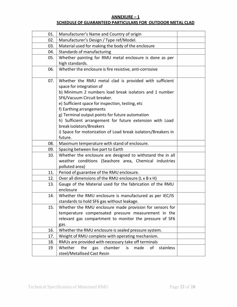
ANNEXURE – 1 SCHEDULE OF GUARANTEED PARTICULARS FOR OUTDOOR METAL CLAD
01. Manufacturer’s Name and Country of origin 02. Manufacturer’s Design / Type ref/Model. 03. Material used for making the body of the enclosure 04. Standards of manufacturing 05. Whether painting for RMU metal enclosure is done as per
high standards.
06. Whether the enclosure is fire resistive, anti-corrosive
07. Whether the RMU metal clad is provided with sufficient space for integration of b) Minimum 2 numbers load break isolators and 1 number SF6/Vacuum Circuit breaker. e) Sufficient space for inspection, testing, etc f) Earthing arrangements g) Terminal output points for future automation h) Sufficient arrangement for future extension with Load break isolators/Breakers i) Space for motorization of Load break isolators/Breakers in future.
08. Maximum temperature with stand of enclosure. 09. Spacing between live part to Earth 10. Whether the enclosure are designed to withstand the in all
weather conditions (Seashore area, Chemical industries polluted area)
11. Period of guarantee of the RMU enclosure. 12. Over all dimensions of the RMU enclosure (L x B x H) 13. Gauge of the Material used for the fabrication of the RMU
enclosure
14. Whether the RMU enclosure is manufactured as per IEC/IS standards to hold SF6 gas without leakage.
15. Whether the RMU enclosure made provision for sensors for temperature compensated pressure measurement in the relevant gas compartment to monitor the pressure of SF6 gas.
16. Whether the RMU enclosure is sealed pressure system. 17. Weight of RMU complete with operating mechanism. 18. RMUs are provided with necessary take off terminals 19 Whether the gas chamber is made of stainless
steel/Metallised Cast Resin

Technical Specification of Motorised RMU Page 23 of 28
ANNEXURE – 2 SCHEDULE OF GUARANTEED PARTICULARS FOR DT BREAKER
01. Manufacturer’s Name and Country of origin 02. Manufacturer’s Design / Type ref/Model. 03. Material used for making the body of the breaker 04. Standards of manufacturing 05. Whether the breakers are manufactured as per
IEC/IS standards
06. Maximum temperature with stand of the breakers
07. 1)Spacing between live part to Earth inside the breaker 2)Spacing between poles
08. Period of guarantee of the breaker 09. Rated frequency 10. Rated voltage 11. Highest system voltage 12. Rated current 13. Short time current rating with duration 14. Certificate or report of short circuit type test 15. Rated operating duty cycle 16. Short circuit breaking current
(a)Symmetrical (b)Symmetrical at rated voltage ©Asymmetrical at rated voltage (i)Per Phase (ii)Average (d)DC Component
17. Arcing time (At rated breaking current) in ms.
18. Opening time
19. Total break time in milli sec. (a)At 10% rated interrupting capacity (b)At rated interrupting capacity
20. Breaking Current (a)Rated out of phase current (b)Rated cable charging current (c )Rated kilometric fault level (d)Rated capacitor breaking current
21. Make time in ms. 22. Maximum temperature rise over ambient
(a)Main contacts Terminals

Technical Specification of Motorised RMU Page 24 of 28
23. Rated restriking voltage at 100% and 50% rated capacity. (a)Amplitude factor (b)Phase factor ©Natural frequency (d)R.R.R.V.(Volts/micro sec.)
24. Dry 1 minute power frequency withstand test voltage (a)Between line terminal and earth KV RMS (b)Between terminals with breaker contacts open KV RMS.
25. 1.2/50 full wave impulse withstand test voltage (a)Between line terminal and earth KVp. (b)Between terminals with breaker contacts open KVp.
26. SF6 /VCB interrupter make 27. Contact separation distance 28. Type of main contacts 29. Contact pressure 30. Contact resistance 31. Life of the interrupter (in number of operations) 32. (i)Tripping at rated current
(ii)Tripping at maximum fault current. (Allowable maximum erotion 3 mm) (iii)Mechanical operations.
33. Details of main contacts making contact with the breaker truck with the panel
34. Control circuit voltage AC/DC. 35. Whether trip free or not 36. Whether all the interlocks provided

Technical Specification of Motorised RMU Page 25 of 28
ANNEXURE – 3 SCHEDULE OF GUARANTEED PARTICULARS FOR LOAD BREAK ISOLATORS & EARTHING
ARRANGEMENTS
SL.NO. DESCRIPTION ISOLATORS EARTHING SWITCH FOR DT & ISOLATOR
01. Manufacturer’s Name and Country of origin 02. Manufacturer’s Design / Type ref/Model. 03. Material used for making the body of the
isolators .
04. Standards of manufacturing 05. Whether the isolators & earth positions are
manufactured as per IEC/IS standards
06. Maximum temperature with stand of the isolators & earth switches
07. 1)Spacing between live part to Earth 2)Spacing between fixed and moving contacts in the open position.
08. Period of guarantee of the isolators 09. Rated frequency 10. Rated voltage 11. Highest system voltage 12. Rated current 13. Short time current rating with duration 14. Certificate or report of short circuit type test 15. Rated operating duty cycle 16. Short circuit breaking current 17. Arcing time (At rated breaking current) in ms. 18. Opening time 19 Whether all the interlocks provided 20 Whether Sufficient arrangements are made to
operate the isolators through SCADA in future, also to be ensured for provision of space for accommodation of motor in future
21 Fault passage indicator 1)Type/Model 2)Self powered Yes/No 3)Current readings 4)Fault currents 5)Phase currents

Technical Specification of Motorised RMU Page 26 of 28
ANNEXURE – 4 SCHEDULE OF GUARANTEED PARTICULARS FOR CURRENT TRANSFORMERS
01. Manufacturer’s Name and Country
of origin Required
02. Manufacturer’s Design / Type ref/Model.
Bidder to specify
03. Applicable Standards 04. 1)Type of CT
2)Ratio
05. Rated Primary current 06. Rated secondary current 07. Rated frequency 08. Transformation ratio 09. Number of cores 10. Rated output
(a) For Core-I
11. Class of insulation 12. Class of accuracy For Protection
13. Short time current rating and its duration
14. Secondary resistance at 70 Deg °C 15. Continuous over load (percentage) 16. One minute power frequency dry
withstand voltage
17. 1.2/50 micro sec. impulse withstand test voltage
18. One minute power frequency withstand test voltage on secondary
19. Instrument safety factor 20. Type of primary winding 21. Literature/leaflets pamphlets
about the current transformer offered
22. Period of guarantee

Technical Specification of Motorised RMU Page 27 of 28
ANNEXURE – 5 SHEDULE OF GUARANTEED TECHNICAL PARTICULARS FOR SELF POWERED MICRO PROCESSOR BASED NUMERICAL RELAYS
01. Manufacturer’s Name and Country of origin 02. Manufacturer’s Design / Type ref/Model. 03. Applicable Standards 04. CurrentSetting
range for (a)Overcurrent relay
IDMT
(b)Earthfault Element
Definite Time
05. Whether the relay has the in-built facilities of IDMT, OL, EL
06. Details of IDMT Characteristics
07. Accuracy for different settings and limits of errors
08. Whether Alpha numeric / LED display 09. Whether compatible for 1 A CT Secondary 10. Whether draw out type 11. Types of case 12. Reset time 13. Burden of relay 14. Maximum and Minimum, operating ambient
air temp.
15. Whether technical literature pamphlets about the relay offered.
16. Period of guarantee. 17. Certificate of Proof for Electro Magnetic
Interference.

Technical Specification of Motorised RMU Page 28 of 28
ANNEXURE – 6
SCHEDULE OF GUARANTEED TECHNICAL PARTICULARS FOR DRAWINGS.
The contractor shall supply the following drawings.
01. RMU 02. General arrangement drawing of panels in station 03. Engineering drawing for each panel including
foundation details
04. Wiring schedule 05. Terminal block arrangement drawing 06. Descriptive operation and maintenance manual for
individual items such as relays, meters, switches recorders etc.
07. Any other drawing required for complete understanding of the equipments supplied.
Three copies of the drawings shall be submitted to this office for approval.
Six copies of the approved drawings and pamphlets shall be supplied to this office. One copy of the approved drawing and pamphlets for the panels pertaining to each substation shall be supplied to the field engineers. These drawings and pamphlets shall be supplied in a neat bound book suitable for easy reading and frequent use. In addition reproducible tracing of the various drawings shall be supplied to this office.