results of the parameter studies and prioritization for ... scp0-ga-2010-265754 rivas_bam_...
TRANSCRIPT

RIVAS
SCP0-GA-2010-265754
RIVAS_BAM_ WP3_D3_3_V04 Page 1 of 50 15/05/12
RIVAS
Railway Induced Vibration Abatement Solutions
Collaborative project
Results of the parameter studies and prioritization for prototype
construction for slab track
Deliverable D3.3
Submission date: 17/05/2012
Project Coordinator:
Bernd Asmussen
International Union of Railways (UIC)
RIVAS
SCP0-GA-2010-265754
RIVAS_BAM_ WP3_D3_3_V04 Page 2 of 50 15/05/12
Title Results of the parameter studies and prioritization for prototype construction for slab track
Domain WP 3, Task 3.4
Date 15/05/2012
Author/Authors Lutz Auersch (BAM)
Partner ALSTOM, BAM, DB, D2S, ER, RailOne
Document Code RIVAS_BAM_ WP3_D3_3_V04
Version 03
Status Final
Dissemination level:
Project co-funded by the European Commission within the Seventh Framework Programme
Dissemination Level
PU Public X
PP Restricted to other programme participants (including the Commission Services)
RE Restricted to a group specified by the consortium (including the Commission) Services)
CO Confidential, only for members of the consortium (including the Commission Services)
Document history
Revision Date Description
1 30/03/2012 First Draft
2 30/04/2012 Second Draft
3 07/05/2012 Third Draft
4 15/05/2012 Final

RIVAS
SCP0-GA-2010-265754
RIVAS_BAM_ WP3_D3_3_V04 Page 3 of 50 15/05/12
1. EXECUTIVE SUMMARY
Slab tracks with wide sleepers on under sleeper pads have been investigated in a parameter
study using a finite-element boundary-element method. The slab track is modelled in detail
by the finite element method. The infinite soil is modelled by the boundary element method
as a homogeneous half-space. The track-soil system is coupled with a rigid wheelset mass
so that the vehicle-track interaction is included. Transfer functions are calculated in
frequency domain without and with vehicle-track interaction, the compliance of the track and
the mobilities of the soil at different distances from the track. Finally, the ratios between the
ground vibration amplitudes with and without mitigation measure are calculated to quantify
the effectiveness of the mitigation measure.
A slab track with an under sleeper pad of a stiffness of kS = 50 106 N/m, which can also be
expressed as a stiffness per area of kS’’ = 3.6 107 N/m3 = 0.036 N/mm3, yields a vehicle-track
resonance frequency of 32 Hz. Whereas the vibration at this frequency are amplified, higher
frequencies are reduced. The insertion loss of this solution is up to 25 dB at 80 Hz for the
ground vibrations in comparison to the reference slab track system (GETRAC system without
sleeper pads but with soft rail pads).
The stiffness of the under sleeper pad has a strong influence on the vibration reduction. The
softest sleeper pad yields the lowest vehicle-track resonance frequency and the best
reduction of the ground vibration. The influence of other parameters has been examined,
such as the stiffness of the rail pads, the stiffness of the slab material, the stiffness of the
sleeper material, and the distance between the sleepers. All these parameters show no or
only a minor influence on the mitigation effect.
As a conclusion, a wide sleeper slab track with under sleeper pads is recommended for
further testing with under sleeper pads as soft as possible and with the highest possible
sleeper mass. The stiffness of the rail pads can be chosen according to acoustical
requirements.

RIVAS
SCP0-GA-2010-265754
RIVAS_BAM_ WP3_D3_3_V04 Page 4 of 50 15/05/12
2. TABLE OF CONTENTS
1. Executive summary ........................................................................................................ 3
2. Table of contents ............................................................................................................ 4
3. Introduction .................................................................................................................... 6
4. Methods of vehicle-track-soil interaction ......................................................................... 8
4.1 Finite-element boundary-element method ............................................................... 8
4.2 Vehicle-track interaction .......................................................................................... 8
4.3 Validation of the methods ........................................................................................ 9
5. Parameter study ............................................................................................................10
5.1 Model of the track and the vehicle ..........................................................................10
5.2 Parameters of the track ..........................................................................................10
5.3 Output quantities ....................................................................................................12
6. Results for the reference track.......................................................................................13
7. Results for slab tracks with wide sleepers on sleeper pads ...........................................14
8. Complementary results .................................................................................................15
8.1 Variation of the rail pad stiffness.............................................................................15
8.2 Variation of the slab stiffness ..................................................................................15
8.3 Variation of the sleeper stiffness.............................................................................15
8.4 Variation of the sleeper distance ............................................................................16
9. Conclusion ....................................................................................................................17
10. References ................................................................................................................18
11. Appendix A – The track model ...................................................................................20
12. Appendix B – Results of the reference slab track .......................................................23
13. Appendix C – Results of the slab track with different under sleeper pads ..................26
14. Appendix D – Insertion loss compared to the reference ballast track .........................32

RIVAS
SCP0-GA-2010-265754
RIVAS_BAM_ WP3_D3_3_V04 Page 5 of 50 15/05/12
15. Appendix E – Complementary results of slab tracks with sleeper pads of 50 kN/mm .37
16. Appendix F – The GETRAC system without and with under sleeper pads .................50

RIVAS
SCP0-GA-2010-265754
RIVAS_BAM_ WP3_D3_3_V04 Page 6 of 50 15/05/12
3. INTRODUCTION
Train-induced vibrations are becoming a growing problem all over Europe. The European
research project “Railway induced vibration abatement solutions (RIVAS)” is focussed on
measures to be applied at the source, at the track, in the transmission and propagation path
and at the vehicles. The work package 3 “Mitigation measures track” includes the task 3.4
which is concerned with “Mitigation measures for slab track” [9]. A combined finite-element
boundary-element model is used to investigate the vibration reduction potential of different
solutions. The influence of the following components, sleeper pads, rail pads, sleeper and
slab stiffness, and the sleeper distance is analysed.
The comparison of different slab track systems will be given in Deliverable 3.11 whereas the
present report concentrates on a particular slab track, the GETRAC system with under
sleeper pads (Figure 16-1). The GETRAC system is characterised as a pre-stressed mono-
block sleeper equipped with an under sleeper pad and laid on a stiff asphalt slab. The wide
sleepers of this slab track system provide a higher elastically supported mass than other slab
track systems (e.g. Sonneville LVT). The higher sleeper mass has been identified as
beneficial for the vibration abatement in Deliverable 3.2.
Tracks with under sleeper pads have been investigated in a wide parameter study in
Deliverable 3.2 for ballasted tracks [8]. It has been found that the parameters with the
strongest influence on the reduction of ground vibration
the stiffness of the under sleeper pad,
the mass of the sleeper,
and the width of the sleeper.
Other parameters, such as
the stiffness of the rail pads,
the bending stiffness of the track,
the stiffness of the ballast,
the sub-soil, the soil, and the layering of the soil
showed no or only a minor influence on the mitigation effect. Most of these results can also
be used for the slab track considered in this report. These parameter variations are not
repeated here, but some more parameters such as
the stiffness of the rail sleeper pad,
the stiffness of the sleeper,
RIVAS
SCP0-GA-2010-265754
RIVAS_BAM_ WP3_D3_3_V04 Page 7 of 50 15/05/12
the stiffness of the slab,
and the distance between the sleepers
are checked for their influence on the mitigation of ground vibrations.
The structure of the report is as follows. The summary, table of content and introduction are
numbered as sections 1, 2, and 3. Section 4 describes the methods of calculation using the
available references, the finite element method for the track, the boundary element method
for the infinitely extended soil, and the interaction with a rigid body model of the vehicle.
Section 5 gives an overview on the parametric study. Section 6 presents the results for the
reference track, Section 7 the results for the isolated slab tracks on different sleeper pads,
and Section 8 the results of the parameter variations. The effectiveness of the mitigation
measures is evaluated by the ratio of the ground vibrations for the isolated slab track and the
reference track. Section 9 presents the conclusions.
RIVAS
SCP0-GA-2010-265754
RIVAS_BAM_ WP3_D3_3_V04 Page 8 of 50 15/05/12
4. METHODS OF VEHICLE-TRACK-SOIL
INTERACTION
4.1 FINITE-ELEMENT BOUNDARY-ELEMENT METHOD
The track-soil systems are modelled by the combined finite-element boundary-element
method [1, 5, 7]. The track including the rails, rail pads, sleepers, under sleeper pads, and
the slab is modelled by the finite element method whereas the infinitely extended soil is
modelled by the boundary element method. The dynamic stiffness matrix of the soil is
established by using the Green’s functions of an elastic layered half-space [3, 7]. All
calculations (Green’s functions, boundary matrix and finite element matrices) are performed
in frequency domain. Special additional methods (within the FEBEM) have been developed
for infinite tracks [6] which are also applied to this study.
The results of a FEBEM calculation are the frequency-dependent compliance uR/FT of the
track (rail displacements uR divided by the dynamic harmonic wheelset load FT on the track)
and mobility vi/FT of the soil (ground particle velocity divided by the dynamic harmonic
wheelset load FT on the track).
4.2 VEHICLE-TRACK INTERACTION
The influence of the vehicle on the ground vibration can be calculated in a second step in
frequency domain as well [4]. The compliance of the track is inverted to the track stiffness
KT = (uR/FT’)-1. A corresponding dynamic stiffness KV of the vehicle can be calculated by
multi-body dynamics [2]. It can be approximated by the inertia of the wheelset KV = -mW2 in
the frequency range of interest. The vehicle is excited by the irregularities s of the track
(alignment and rail roughness) and the vehicle (out-of-roundness and roughness of the
wheel).
The transfer function between the irregularities s and the force FT on the track can be
calulated as
VT
VTT
KK
KK
s
F
The vehicle-track interaction can also be expressed as

RIVAS
SCP0-GA-2010-265754
RIVAS_BAM_ WP3_D3_3_V04 Page 9 of 50 15/05/12
VT
T
V
T
KK
K
F
F
if the force FV = -KVs is used which is generated by the vehicle and the irregularities in case
of a rigid track.
After the vehicle-track interaction is solved, the ground vibration can be calculated by
multiplying the vehicle-track transfer function and the mobilities of the soil
VT
T
T
i
V
T
T
i
V
i
KK
K
F
v
F
F
F
v
F
v
.
At the end, two different tracks (isolated and un-isolated track) are compared by comparing
the vibration at the same soil point xi. The velocity ratio vi,U /vi,I of the un-isolated and isolated
track can be built by the transfer functions without specifying the excitation
IVT
T
T
i
UVT
T
T
i
V
Ii
V
Ui
Ii
Ui
KK
K
F
v
KK
K
F
v
F
v
F
v
v
v
,
,
,
,
,
,
.
4.3 VALIDATION OF THE METHODS
The present methods of track dynamics and vehicle-track interaction have been used since
1982 [10] for many reports and publications. They have been verified by comparison with
other methods [11] and with several measurements [2, 4, 5, 10].
The methods are used for a single fixed axle load, not for moving train sets. This is sufficient
to determine the frequency-dependent efficiency of the mitigation measures to reduce the
ground response to dynamic loads. Effects on the excitation of the ground vibration such as
reduced track errors and a reduced stiffness variation (parametrical excitation) are not
discussed here, see [2, 4] for corresponding methods and results. Additional software tools
have been developed by BAM for the prediction of railway induced vibration.

RIVAS
SCP0-GA-2010-265754
RIVAS_BAM_ WP3_D3_3_V04 Page 10 of 50 15/05/12
5. PARAMETER STUDY
5.1 MODEL OF THE TRACK AND THE VEHICLE
Figure 11-1 to Figure 11-3 show the finite element model of the track which has a length of
6.68 m. It consists of two rails, eleven sleepers with rail pads and under sleeper pads, a slab,
and the infinite soil. End elements at the rails approximate the behaviour of an infinite track.
The track is excited by a dynamic harmonic axle load (a pair of vertical forces) which acts on
the rails above the central sleeper.
The only vehicle parameter is
the wheelset mass mW = 1500 kg
5.2 PARAMETERS OF THE TRACK
A slab track with wide sleepers on under sleeper pads with the following parameters is
analysed:
bending stiffness of the rails (UIC60) EI = 2 x 2.1 1011 x 3.0 10-5 Nm2 = 12.6 106 Nm2,
mass per length of the rails m’R = 2 x 60 kg/m,
distance of the rail pads d = 0.6 m
stiffness of the rail pads kR = 300 106 N/m,
modulus of elasticity of the sleepers ES = 3 1010 N/m2,
mass density of the sleepers S = 2.5 103 kg/m3,
length of the sleepers aS = 2.6 m,
height of the sleepers hS = 0.2 m,
width of the sleepers bS = 0.52 m ,
stiffness of the sleeper pads kS = 50 106 N/m,
width of the slab aB1 = 3.2 m,
height of the slab hB = 0.3 m,
elasticity modulus of the slab EP = 4 109 N/m2,

RIVAS
SCP0-GA-2010-265754
RIVAS_BAM_ WP3_D3_3_V04 Page 11 of 50 15/05/12
shear modulus of the soil G = 8 107 N/m2,
shear wave velocity of the soil vS = 200 m/s
mass density of the soil = 2 103 kg/m3,
Poisson’s ratio of the soil = 0.33,
hysteretic damping of the soil D = 2.5 %,
hysteretic damping of the elastic elements DP = DS = 10 %.
The following parameter variations are performed in this deliverable:
stiffness of the sleeper pads kS = 25, 50, 100, 200 106 N/m,
stiffness of the rail pads kR = 300, 1000 106 N/m,
elasticity modulus of the slab EP = 0.48, 1, 4, 10, 30 109 N/m2,
modulus of elasticity of the sleepers ES = 1.5, 3, 6 1010 N/m2,
distance of the rail pads d = 0.6, 0.65 m.
More parameter variations, for example variations of the sub-soil, the soil, and the layering of
the soil have been analysed in Deliverable 3.2 for ballasted tracks. The minor influence on
the reduction of ground vibration could also apply for isolated slab tracks.
The stiffness of the under sleeper pads
kS = 25, 50, 100, 200 106 N/m
can also be expressed as a stiffness per area
k’’S = 18, 36, 72, 144 106 N/m3 or
k’’S = 0.018, 0.036, 0.072, 0.144 N/mm3 (according to DIN 45673).
For real under sleeper pads, it must be observed that they have different stiffnesses for the
high static load and the small additional dynamic loads. The dynamic stiffness values must
be applied for the reduction of the ground vibration due to dynamic loads.
A slab track without sleeper pads is calculated as a reference slab track. The reference slab
track has the same parameters as given before but it has no under sleeper pads. The
stiffness of the rail pads is taken as
kR = 40 106 N/m,

RIVAS
SCP0-GA-2010-265754
RIVAS_BAM_ WP3_D3_3_V04 Page 12 of 50 15/05/12
so that the reference slab track has a realistic compliance. (In addition, the reference ballast
track of Deliverable 3.2 is used in Appendix D to facilitate more comparisons.)
5.3 OUTPUT QUANTITIES
The following quantities are presented as the results of the track-soil and the vehicle-track
interaction:
The compliance uR/FT or uR/FV of the track, without and with vehicle-track interaction,
the mobility vi/FT or vi/FV of the soil at 4, 8, 16, and 32 m from the centre of the track, without
and with vehicle-track interaction,
and the ground vibration ratios vi,U /vi,I (insertion loss of the slab track with under sleeper pad)
at 4, 8, 16, and 32 m from the centre of the track.
All ground vibration ratios vi,U /vi,I and all ground vibrations (mobilities vi/F) in Appendix C and
E are calculated with vehicle-track interaction.

RIVAS
SCP0-GA-2010-265754
RIVAS_BAM_ WP3_D3_3_V04 Page 13 of 50 15/05/12
6. RESULTS FOR THE REFERENCE TRACK
At first, the results of the FEBEM calculation without any vehicle-track interaction are shown
in Figure 12-1a. The track compliance is almost constant at uR/FT = 6 10-9 m/N for all
frequencies. That means a rail displacement of 0.6 mm under a 100 kN axle load. At
frequencies higher than 100 Hz, a weak increase of the compliance is observed. The
mobilities of the soil (Figure 12-2a) show some characteristic changes in the frequency range
of interest. At first, the soil mobilities increase with frequency up to 40 Hz. At higher
frequencies, the mobilities turn to be constant or decreasing which is due to the material
damping of the soil, which has its strongest effect on the far-field points of the soil, and due
to the distribution of the excitation force across the track.
The compliance of the track and the dynamic stiffness of the vehicle (wheelset) yield the
vehicle-track transfer function. The compliance of the track is multiplied by this vehicle track
transfer function in Figure 12-1b, and including the vehicle track interaction yields
considerably different results. Due to the soft rail pads of the reference track, a clear vehicle-
track resonance can be observed at 50 Hz and a strong reduction of rail displacements at
higher frequencies. The soil mobilities are multiplied by the vehicle-track transfer function in
Figure 12-2b, and the soil mobilities at 4, 8, 16, and 32 m show the same vehicle-track
resonance at 50 Hz and the strong decrease at higher frequencies as the rail compliance
with vehicle-track interaction.

RIVAS
SCP0-GA-2010-265754
RIVAS_BAM_ WP3_D3_3_V04 Page 14 of 50 15/05/12
7. RESULTS FOR SLAB TRACKS WITH WIDE
SLEEPERS ON SLEEPER PADS
The most important parameter to reduce the train induced ground vibration by under sleeper
pads is the stiffness of the pads. The stiffness of the under sleeper pads is varied as kS = 25,
50, 100, 200 106 N/m. Stiffer under sleeper pads are possible, but they have almost no
positive effect below 100 Hz.
The softest under sleeper pad yields a track compliance higher than 0.01 mm/kN (1 mm per
100 kN axle load, Figure 13-1a). Stiffer under sleeper pads are below this value. All
investigated under sleeper pads have track-pad resonances below 160 Hz, starting at 25 Hz
for the softest and ending at 80 Hz for the stiffest sleeper pad. Including the wheelset mass
yields a somewhat lower vehicle-track resonance frequency between 22 and 50 Hz (Figure
13-1b). The same lower resonance frequencies are found for the ground vibrations at the
different distances (Figure 13-2 and Figure 13-3). The resonance amplification has lower
values in case of stiffer sleeper pads. After the resonance, a strong decrease of the transfer
functions is observed. The softest under sleeper pads yield the strongest reduction. The
reduction is quantified by the ratio of the ground vibration of the reference track to the ground
vibration of the slab track with sleeper pads (Figure 13-4 and Figure 13-5). These ratios
(insertion losses) start at the value 1 (0 dB) at low frequencies. They decrease until the
vehicle-track resonance of the isolated track is reached at 25 to 40 Hz. A strong increase
follows up to 64 or 80 Hz where the maximum value of the insertion loss is found. At higher
frequencies, the insertion loss varies around lower values. For the stiffness kS = 50 106 N/m
of the sleeper pad, the highest insertion loss is around 20 dB at 64 or 80 Hz. The maximum
insertion loss is higher for the softest pad stiffness (20 to 30 dB) and lower for the stiffer
sleeper pads. It is also higher for the far-field points where the sleeper pad of
kS = 50 106 N/m yields an insertion loss of 25 dB. The high insertion loss values are due to
the resonance of the reference slab track and changes of the load distribution which have
different effects at different distances from the track. Therefore, the insertion loss should be
assured by using different observation points (Figure 13-4 and Figure 13-5) and different
reference tracks (see Appendix D). The minimum of the insertion loss due to the vehicle-
track resonance of the isolated track is smallest for the softest sleeper pad reaching a value
of -10 dB.
RIVAS
SCP0-GA-2010-265754
RIVAS_BAM_ WP3_D3_3_V04 Page 15 of 50 15/05/12
8. COMPLEMENTARY RESULTS
The analyses in the following Sections have been done to check if the effectiveness of the
under sleeper pads is influenced by certain parameters. The stiffness of the under sleeper
pad is kept constant at kS = 50 106 N/m.
8.1 VARIATION OF THE RAIL PAD STIFFNESS
In deliverable 3.2 of RIVAS [8], it has been found that a soft rail pad could give a worse
efficiency of soft sleeper pads. Therefore, the isolated slab track is also calculated with a
stiffer rail pad of kR = 1000 kN/mm to check whether the rail pad of kR = 300 kN/mm is
already stiff enough to achieve the optimum effect of the under sleeper pad. As a result, the
static displacement is reduced by 1 % if the stiff rail pads are used (Figure 15-1). Some small
differences can be found at high frequencies for the track compliance as well as for the soil
mobilities in Figure 15-2 and Figure 15-3, but there is no clear tendency that the stiffer rail
pads can improve the mitigation.
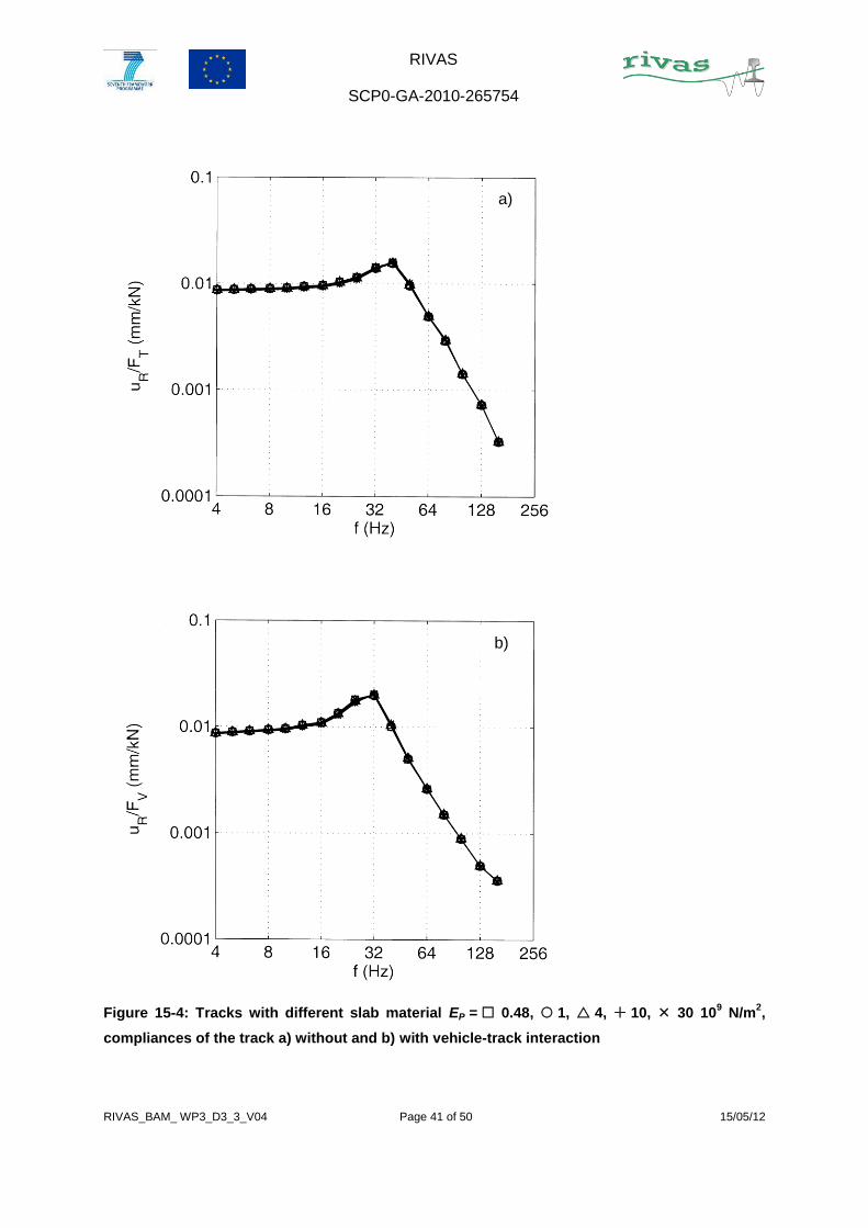
8.2 VARIATION OF THE SLAB STIFFNESS
The slab material has been varied in a wide range. The elasticity modulus of three different
asphalt materials has been chosen, and in addition a higher elasticity modulus (the elasticity
modulus of concrete) and a lower elasticity modulus (comparable to the elasticity modulus of
a stiff ballast) are taken in to account. The compliances of the tracks with different slab
materials are identical (Figure 15-4). The differences are found for the ground vibration at
high frequencies above 50 Hz (Figure 15-5 and Figure 15-6). The differences are usually in
the order of the different elastic moduli, but the stiffest slab material yields at some
frequencies the highest and at some frequencies the lowest value. A general tendency, that
a stiffer slab material can improve the mitigation effect of the under sleeper pads, must be
denied. A similar minor influence on the track and ground vibration might be expected for the
slab mass.
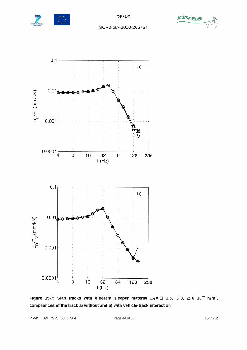
8.3 VARIATION OF THE SLEEPER STIFFNESS
The elasticity modulus of concrete varies in certain limits. In the present report a wider range
of stiffness values, 1.5 to 6 1010 N/m2, has been examined to find clearer effects. Some small

RIVAS
SCP0-GA-2010-265754
RIVAS_BAM_ WP3_D3_3_V04 Page 16 of 50 15/05/12
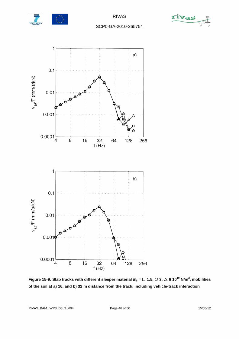
differences have been found in Figure 15-7 to Figure 15-9 for frequencies above 80 Hz. At
80 Hz, the stiffest material yields the highest amplitudes whereas at 160 Hz, the softest
material has the highest amplitudes of the three materials. There is no clear order of
amplitudes, and the differences vary with frequency. So it is concluded that there is an
influence of the sleeper stiffness but without a clear advantage for the stiffer or softer
material.
8.4 VARIATION OF THE SLEEPER DISTANCE
On Figure 15-10 to Figure 15-12 two sleeper distances are compared, d = 0.6 m and 0.65 m.
The displacements above the sleeper differ by 4 %. The ground vibration curves are almost
identical. So it is concluded that the small variation of the sleeper distance of less than 10 %
yields only negligible changes in the behaviour and effectiveness of the under sleeper pads.
The distance between the sleepers has an influence on the parametric excitation which has
not been studied here.

RIVAS
SCP0-GA-2010-265754
RIVAS_BAM_ WP3_D3_3_V04 Page 17 of 50 15/05/12
9. CONCLUSION
Slab tracks with wide sleepers on under sleeper pads have been investigated in a parameter
study using a finite-element boundary-element method. The influence of different parameters
on the reduction of the ground vibration has been investigated.
The stiffness of the under sleeper pad has a strong influence on the vibration
reduction. The softest sleeper pad yields the lowest vehicle-track resonance
frequency and the best reduction of the ground vibration. For example, the sleeper
pad stiffness of kS = 50 106 N/m yields a vehicle-track resonance frequency of 32 Hz
and a maximum insertion loss of 25 dB at 80 Hz.
The influence of other parameters has been examined, such as
the stiffness of the rail pads,
the stiffness of the slab material,
the stiffness of the sleeper material,
and the distance between the sleepers.
All these parameters show no or only a minor influence on the mitigation effect.
These results are complementary to the results in Deliverable 3.2 for ballasted tracks on
sleeper pads where
the mass of the sleeper,
and the width of the sleeper
showed a positive effect on the vibration reduction, and
the stiffness of the sub-soil,
the stiffness and the layering of the soil
showed no or only a minor influence on the mitigation effect.
As a conclusion, a wide sleeper slab track with under sleeper pads is recommended for
further testing with under sleeper pads as soft as possible and with the highest possible
sleeper mass. The stiffness of the rail pads can be chosen according to acoustical
requirements.

RIVAS
SCP0-GA-2010-265754
RIVAS_BAM_ WP3_D3_3_V04 Page 18 of 50 15/05/12
10. REFERENCES
[1] L. Auersch, G. Schmid: A simple boundary element formulation and its application to
wavefield excited soil-structure interaction. Earthquake Engineering and Structural
Dynamics 19, 1990, 931-947.
[2] L. Auersch: Zur Parametererregung des Rad-Schiene-Systems: Berechnung der
Fahrzeug-Fahrweg-Untergrund-Dynamik und experimentelle Verifikation am
Hochgeschwindigkeitszug Intercity Experimental. Ingenieur-Archiv 60, 1990, 141-156.
[3] L. Auersch: Wave propagation in layered soil: theoretical solution in wavenumber
domain and experimental results of hammer and railway traffic excitation. Journal of
Sound and Vibration 173, 1994, 233-264.
[4] L. Auersch: The excitation of ground vibration by rail traffic: Theory of vehicle-track-
soil interaction and measurements on high-speed lines. Journal of Sound and
Vibration 284, 2005, 103-132.
[5] L. Auersch: Dynamics of the railway track and the underlying soil: the boundary-
element solution, theoretical results and their experimental verification. Vehicle
System Dynamics 43, 2005, 671-695.
[6] L. Auersch: Dynamic axle loads on tracks with and without ballast mats – numerical
results of three-dimensional vehicle-track-soil models. Journal of Rail and Rapid
Transit 220, 2006, 169-183.
[7] L. Auersch: Wave propagation in the elastic half-space due to an interior load and its
application to ground vibration problems and buildings on pile foundations. Soil
Dynamics and Earthquake Engineering 30, 2010, 925–936.
[8] L. Auersch: Mitigation measures for ballasted tracks – sleeper, sleeper pads and
substructure – results from the finite-element boundary-element method. Appendix B
in B. Faure, E. Bongini, BAM, KUL: Results of the parameter studies and prioritization
for prototype construction for ballasted track. Deliverable 3.2 of RIVAS, 2012.
[9] „Railway Induced Vibration Abatement Solutions“, Description of Work. Collaborative
project for theme SST.2010.1.1-3. “Attenuation of ground-borne vibration affecting
residents near railway lines” in the seventh framework programme.

RIVAS
SCP0-GA-2010-265754
RIVAS_BAM_ WP3_D3_3_V04 Page 19 of 50 15/05/12
[10] W. Rücker: Dynamic interaction of a railroad-bed with the subsoil. Proc. Conf. Soil
Dynamics and Earthquake Engineering. Southampton 1982, 435-448.
[11] W. Rücker, L. Auersch, M. Baeßler, K. Knothe, K. Popp, S. Savidis, G. Schmid: A
Comparative Study of Results from Numerical Track-Subsoil Calculations. In: K.
Popp, W. Schiehlen (eds.); Lecture Notes in Applied Mechanics “System Dynamics
and Long-Term Behaviour of Railway Vehicles, Track and Subgrade”, Berlin:
Springer-Verlag, 2003, 471-488.

RIVAS
SCP0-GA-2010-265754
RIVAS_BAM_ WP3_D3_3_V04 Page 20 of 50 15/05/12
11. APPENDIX A – THE TRACK MODEL
Figure 11-1: Finite-element-model of the slab track
Rail Rail pad Sleeper Sleeper pad Slab

RIVAS
SCP0-GA-2010-265754
RIVAS_BAM_ WP3_D3_3_V04 Page 21 of 50 15/05/12
Figure 11-2: Finite-element-model of the slab track, top view

RIVAS
SCP0-GA-2010-265754
RIVAS_BAM_ WP3_D3_3_V04 Page 22 of 50 15/05/12
Figure 11-3: Finite-element-model of the slab track, view along and across the track
Rail Rail pad Sleeper Sleeper pad Slab

RIVAS
SCP0-GA-2010-265754
RIVAS_BAM_ WP3_D3_3_V04 Page 23 of 50 15/05/12
12. APPENDIX B – RESULTS OF THE REFERENCE
SLAB TRACK

RIVAS
SCP0-GA-2010-265754
RIVAS_BAM_ WP3_D3_3_V04 Page 24 of 50 15/05/12
Figure 12-1: Reference track, compliance of the track a) without and b) with vehicle-track
interaction
b)
a)

RIVAS
SCP0-GA-2010-265754
RIVAS_BAM_ WP3_D3_3_V04 Page 25 of 50 15/05/12
Figure 12-2: Reference track, mobilities of the soil at 4, 8, 16, 32 m, a) without and
b) with vehicle-track interaction
b)
a)

RIVAS
SCP0-GA-2010-265754
RIVAS_BAM_ WP3_D3_3_V04 Page 26 of 50 15/05/12
13. APPENDIX C – RESULTS OF THE SLAB TRACK
WITH DIFFERENT UNDER SLEEPER PADS

RIVAS
SCP0-GA-2010-265754
RIVAS_BAM_ WP3_D3_3_V04 Page 27 of 50 15/05/12
Figure 13-1: Slab tracks on different under sleeper pads, kS = 25, 50, 100, 200 kN/mm,
compliances of the track a) without and b) with vehicle-track interaction
b)
a)

RIVAS
SCP0-GA-2010-265754
RIVAS_BAM_ WP3_D3_3_V04 Page 28 of 50 15/05/12
Figure 13-2: Slab tracks on different under sleeper pads, kS = 25, 50, 100, 200 kN/mm,
mobilities of the soil at a) 4, b) 8 m distance from the track, including vehicle-track interaction
b)
a)

RIVAS
SCP0-GA-2010-265754
RIVAS_BAM_ WP3_D3_3_V04 Page 29 of 50 15/05/12
Figure 13-3: Slab tracks on different under sleeper pads, kS = 25, 50, 100, 200 kN/mm,
mobilities of the soil at a) 16, and b) 32 m distance from the track, including vehicle-track
interaction
b)
a)

RIVAS
SCP0-GA-2010-265754
RIVAS_BAM_ WP3_D3_3_V04 Page 30 of 50 15/05/12
Figure 13-4: Slab tracks on different under sleeper pads, kS = 25, 50, 100, 200 kN/mm,
insertion loss (reference slab track divided by isolated slab track) of the ground vibration at
a) 4, b) 8 m distance from the track
b)
a)

RIVAS
SCP0-GA-2010-265754
RIVAS_BAM_ WP3_D3_3_V04 Page 31 of 50 15/05/12
Figure 13-5: Slab tracks on different under sleeper pads, kS = 25, 50, 100, 200 kN/mm,
insertion loss (reference slab track divided by isolated slab track) of the ground vibration at
a) 16, and b) 32 m distance from the track
b)
a)

RIVAS
SCP0-GA-2010-265754
RIVAS_BAM_ WP3_D3_3_V04 Page 32 of 50 15/05/12
14. APPENDIX D – INSERTION LOSS COMPARED TO
THE REFERENCE BALLAST TRACK
The results for the slab track are additionally compared to the ballasted reference track which
is defined in the deliverable 3.2 “Mitigation for ballasted tracks” [8].

RIVAS
SCP0-GA-2010-265754
RIVAS_BAM_ WP3_D3_3_V04 Page 33 of 50 15/05/12
Figure 14-1: Slab tracks on different under sleeper pads, kS = 25, 50, 100, 200 kN/mm,
insertion loss (reference ballast track divided by isolated slab track) of the ground vibration at
a) 4, b) 8 m distance from the track

RIVAS
SCP0-GA-2010-265754
RIVAS_BAM_ WP3_D3_3_V04 Page 34 of 50 15/05/12
Figure 14-2: Slab tracks on different under sleeper pads, kS = 25, 50, 100, 200 kN/mm,
insertion loss (reference ballast track divided by isolated slab track) of the ground vibration at
a) 16, b) 32 m distance from the track

RIVAS
SCP0-GA-2010-265754
RIVAS_BAM_ WP3_D3_3_V04 Page 35 of 50 15/05/12
Figure 14-3: Reference slab track, insertion loss (reference ballast track divided by reference
slab track) of the ground vibration at a) 4, b) 8 m distance from the track

RIVAS
SCP0-GA-2010-265754
RIVAS_BAM_ WP3_D3_3_V04 Page 36 of 50 15/05/12
Figure 14-4: Reference slab track, insertion loss (reference ballast track divided by reference
slab track) of the ground vibration at a) 16, b) 32 m distance from the track

RIVAS
SCP0-GA-2010-265754
RIVAS_BAM_ WP3_D3_3_V04 Page 37 of 50 15/05/12
15. APPENDIX E – COMPLEMENTARY RESULTS OF
SLAB TRACKS WITH
SLEEPER PADS OF 50 KN/MM

RIVAS
SCP0-GA-2010-265754
RIVAS_BAM_ WP3_D3_3_V04 Page 38 of 50 15/05/12
Figure 15-1: Tracks with different rail pads kR = 300, 1000 kN/mm, compliances of the track
a) without and b) with vehicle-track interaction
b)
a)

RIVAS
SCP0-GA-2010-265754
RIVAS_BAM_ WP3_D3_3_V04 Page 39 of 50 15/05/12
Figure 15-2: Tracks with different rail pads kR = 300, 1000 kN/mm, mobilities of the soil at
a) 4, b) 8 m distance from the track, including vehicle-track interaction
b)
a)

RIVAS
SCP0-GA-2010-265754
RIVAS_BAM_ WP3_D3_3_V04 Page 40 of 50 15/05/12
Figure 15-3: Tracks with different rail pads kR = 300, 1000 kN/mm, mobilities of the soil at
a) 16, and b) 32 m distance from the track, including vehicle-track interaction
b)
a)
RIVAS
SCP0-GA-2010-265754
RIVAS_BAM_ WP3_D3_3_V04 Page 41 of 50 15/05/12
Figure 15-4: Tracks with different slab material EP = 0.48, 1, 4, 10, 30 109 N/m
2,
compliances of the track a) without and b) with vehicle-track interaction
b)
a)

RIVAS
SCP0-GA-2010-265754
RIVAS_BAM_ WP3_D3_3_V04 Page 42 of 50 15/05/12
Figure 15-5: Tracks with different slab material EP = 0.48, 1, 4, 10, 30 109 N/m
2,
mobilities of the soil at a) 4, and b) 8 m distance from the track, including vehicle-track
interaction
b)
a)

RIVAS
SCP0-GA-2010-265754
RIVAS_BAM_ WP3_D3_3_V04 Page 43 of 50 15/05/12
Figure 15-6: Tracks with different slab material EP = 0.48, 1, 4, 10, 30 109 N/m
2,
mobilities of the soil at a) 16, and b) 32 m distance from the track, including vehicle-track
interaction
b)
a)
RIVAS
SCP0-GA-2010-265754
RIVAS_BAM_ WP3_D3_3_V04 Page 44 of 50 15/05/12
Figure 15-7: Slab tracks with different sleeper material ES = 1.5, 3, 6 1010
N/m2,
compliances of the track a) without and b) with vehicle-track interaction
b)
a)

RIVAS
SCP0-GA-2010-265754
RIVAS_BAM_ WP3_D3_3_V04 Page 45 of 50 15/05/12
Figure 15-8: Slab tracks with different sleeper material ES = 1.5, 3, 6 1010
N/m2, mobilities
of the soil at a) 4, b) 8 m distance from the track, including vehicle-track interaction
b)
a)
RIVAS
SCP0-GA-2010-265754
RIVAS_BAM_ WP3_D3_3_V04 Page 46 of 50 15/05/12
Figure 15-9: Slab tracks with different sleeper material ES = 1.5, 3, 6 1010
N/m2, mobilities
of the soil at a) 16, and b) 32 m distance from the track, including vehicle-track interaction
b)
a)

RIVAS
SCP0-GA-2010-265754
RIVAS_BAM_ WP3_D3_3_V04 Page 47 of 50 15/05/12
Figure 15-10: Slab tracks with different sleeper distances d = 0.6, 0.65 m, compliances of
the track a) without and b) with vehicle-track interaction
b)
a)

RIVAS
SCP0-GA-2010-265754
RIVAS_BAM_ WP3_D3_3_V04 Page 48 of 50 15/05/12
Figure 15-11: Slab tracks with different sleeper distances d = 0.6, 0.65 m, mobilities of the
soil at a) 4, and b) 8 m distance from the track, including vehicle-track interaction
b)
a)

RIVAS
SCP0-GA-2010-265754
RIVAS_BAM_ WP3_D3_3_V04 Page 49 of 50 15/05/12
Figure 15-12: Slab tracks with different sleeper distances d = 0.6, 0.65 m, mobilities of the
soil at a) 16, and b) 32 m distance from the track, including vehicle-track interaction
b)
a)

RIVAS
SCP0-GA-2010-265754
RIVAS_BAM_ WP3_D3_3_V04 Page 50 of 50 15/05/12
16. APPENDIX F – THE GETRAC SYSTEM WITHOUT
AND WITH UNDER SLEEPER PADS
a)
b)
Figure 16-1: The GETRAC System a) without and b) with under sleeper pads