vipa networking solutions€¦ · · 2016-03-154.4 using traffic prioritization..... 57 4.4.1 the...
TRANSCRIPT

PNS | 911-2PNx0 | ManualHB165 | PNS | 911-2PNx0 | GB | 16-06
VIPA Networking Solutions
PROFINET Switches PN5-RD/PN8-RD

911-2PNx0_000_PN5/8-RD,1,GB - © 2016
VIPA GmbHOhmstr. 491074 HerzogenaurachTelephone: +49 9132 744-0Fax: +49 9132 744-1864Email: [email protected]: www.vipa.com
Table of contents1 General...................................................................................... 6
1.1 Copyright © VIPA GmbH ................................................... 61.2 About this manual.............................................................. 71.3 Safety information.............................................................. 8
2 Hardware Installation............................................................. 102.1 Panel Layout.................................................................... 102.2 Mounting Dimensions....................................................... 112.3 DIN-Rail Mounting............................................................ 112.4 Wall Mounting (optional).................................................. 122.5 ATEX Information............................................................. 122.6 Wiring Requirements........................................................ 132.7 Grounding the Switch....................................................... 132.8 Wiring the Relay Contact................................................. 142.9 Wiring the Redundant Power Inputs................................ 142.10 Communication Connections......................................... 152.10.1 10/100BaseT(X) Ethernet Port Connection................. 152.10.2 100BaseFX Ethernet Port Connection........................ 162.11 Redundant Power Inputs................................................ 172.12 Relay Contact................................................................. 172.13 Turbo Ring DIP Switch Settings..................................... 182.14 LED Indicators................................................................ 192.15 Auto MDI/MDI-X Connection.......................................... 202.16 Specifications................................................................. 20
3 Getting Started....................................................................... 233.1 Serial Console Configuration (115200, None, 8, 1,
VT100)............................................................................. 233.2 Configuration by Telnet Console...................................... 273.3 Configuration by Web Browser........................................ 303.4 Disabling Telnet and Browser Access.............................. 31
4 Featured Functions................................................................ 334.1 Configuring Basic Settings............................................... 334.1.1 System Identification..................................................... 334.1.2 Password...................................................................... 354.1.3 Accessible IP List.......................................................... 364.1.4 Port Settings.................................................................. 374.1.5 Network Parameters..................................................... 404.1.6 GARP Timer Parameters.............................................. 444.1.7 System Time Settings................................................... 454.1.8 Turbo Ring DIP Switch.................................................. 474.1.9 System File Update....................................................... 484.1.10 Restart......................................................................... 504.1.11 Reset to Factory Default............................................. 514.2 Loop Protection................................................................ 514.3 Configuring SNMP........................................................... 524.3.1 SNMP Read/Write Settings........................................... 534.3.2 Trap Settings................................................................. 554.3.3 Private MIB Information................................................. 56
VIPA Networking Solutions Table of contents
HB165 | PNS | 911-2PNx0 | GB | 16-06 3
4.4 Using Traffic Prioritization................................................ 574.4.1 The Traffic Prioritization Concept.................................. 574.4.2 Configuring Traffic Prioritization.................................... 604.5 Using Virtual LAN............................................................. 634.5.1 The Virtual LAN (VLAN) Concept.................................. 634.5.2 Sample Applications of VLANs Using VIPA switches. . . 664.5.3 VLAN Settings............................................................... 674.5.4 VLAN Table................................................................... 694.6 Using Multicast Filtering................................................... 704.6.1 The Concept of Multicast Filtering................................. 704.6.2 Configuring IGMP Snooping......................................... 734.6.3 Static Multicast MAC Addresses................................... 764.6.4 Configuring GMRP........................................................ 764.6.5 GMRP Table................................................................. 774.7 Using Bandwidth Management........................................ 784.7.1 Configuring Bandwidth Management............................ 784.8 Using Auto Warning......................................................... 824.8.1 Configuring Email Warning........................................... 834.8.2 Configuring Relay Warning........................................... 864.9 Using Line-Swap-Fast-Recovery..................................... 884.9.1 Configuring Line-Swap Fast Recovery.......................... 884.10 Using Set Device IP....................................................... 894.10.1 Configuring Set Device IP........................................... 904.10.2 Configuring DHCP Relay Agent.................................. 904.11 Using Diagnosis............................................................. 934.11.1 Mirror Port................................................................... 934.11.2 Ping............................................................................. 944.11.3 LLDP Function............................................................ 954.12 Using Monitor................................................................. 964.12.1 Monitor by Switch........................................................ 964.12.2 Monitor by Port............................................................ 964.13 Using the MAC Address Table....................................... 974.14 Using Event Log............................................................. 984.15 Using Syslog.................................................................. 99
5 Communication Redundancy............................................. 1015.1 Introduction to Communication Redundancy................. 1015.2 Turbo Ring..................................................................... 1035.2.1 The Turbo Ring Concept............................................. 1035.2.2 Setting up "Turbo Ring" or "Turbo Ring V2"................ 1035.2.3 Configuring “Turbo Ring” and “Turbo Ring V2”........... 1105.3 Turbo Chain................................................................... 1185.3.1 The Turbo Chain Concept........................................... 1185.3.2 Setting Up Turbo Chain............................................... 1195.3.3 Configuring "Turbo Chain"........................................... 1195.4 STP/RSTP/MSTP........................................................... 1225.4.1 The STP/RSTP/MSTP Concept.................................. 1225.4.2 STP Example.............................................................. 1255.4.3 Using STP on a Network with Multiple VLANs............ 1265.4.4 Configuring STP/RSTP............................................... 127
VIPA Networking SolutionsTable of contents
HB165 | PNS | 911-2PNx0 | GB | 16-06 4
5.4.5 Configuration Limits of STP/RSTP.............................. 1296 Industrial Protocols ............................................................ 131
6.1 MODBUS/TCP MAP...................................................... 1316.1.1 Introduction................................................................. 1316.1.2 Data Format and Function Code................................. 1316.1.3 Configuring MODBUS/TCP on VIPA Switches........... 1316.1.4 MODBUS Data Map and Information Interpretation of
VIPA Switches............................................................. 1326.2 EtherNet/IP..................................................................... 1426.3 PROFINET I/O............................................................... 1426.3.1 Introduction................................................................. 1426.3.2 PROFINET Environmental Introductions.................... 1436.3.3 Configuring PROFINET I/O on VIPA Switches........... 1446.3.4 Addressing of I/O Data in PROFINET I/O Based on
Slot and Sub-Slots...................................................... 1446.3.5 PROFINET Attributes.................................................. 1456.3.6 Siemens STEP®7 Integration...................................... 1506.3.7 Monitoring the Switch.................................................. 166
VIPA Networking Solutions Table of contents
HB165 | PNS | 911-2PNx0 | GB | 16-06 5
1 General1.1 Copyright © VIPA GmbH
This document contains proprietary information of VIPA and is not tobe disclosed or used except in accordance with applicable agree-ments.This material is protected by the copyright laws. It may not be repro-duced, distributed, or altered in any fashion by any entity (eitherinternal or external to VIPA), except in accordance with applicableagreements, contracts or licensing, without the express written con-sent of VIPA and the business management owner of the material.For permission to reproduce or distribute, please contact: VIPA,Gesellschaft für Visualisierung und Prozessautomatisierung mbHOhmstraße 4, D-91074 Herzogenaurach, GermanyTel.: +49 9132 744 -0Fax.: +49 9132 744-1864EMail: [email protected]://www.vipa.com
Every effort has been made to ensure that the informationcontained in this document was complete and accurate atthe time of publishing. Nevertheless, the authors retain theright to modify the information.This customer document describes all the hardware unitsand functions known at the present time. Descriptions maybe included for units which are not present at the customersite. The exact scope of delivery is described in therespective purchase contract.
Hereby, VIPA GmbH declares that the products and systems are incompliance with the essential requirements and other relevant provi-sions. Conformity is indicated by the CE marking affixed to theproduct.
For more information regarding CE marking and Declaration of Con-formity (DoC), please contact your local VIPA customer serviceorganization.
All Rights Reserved
CE Conformity Declara-tion
Conformity Information
VIPA Networking SolutionsGeneralCopyright © VIPA GmbH
HB165 | PNS | 911-2PNx0 | GB | 16-06 6
VIPA, SLIO, System 100V, System 200V, System 300V, System300S, System 400V, System 500S and Commander Compact areregistered trademarks of VIPA Gesellschaft für Visualisierung undProzessautomatisierung mbH.SPEED7 is a registered trademark of profichip GmbH.SIMATIC, STEP, SINEC, TIA Portal, S7-300 and S7-400 are regis-tered trademarks of Siemens AG.Microsoft and Windows are registered trademarks of Microsoft Inc.,USA.Portable Document Format (PDF) and Postscript are registered trade-marks of Adobe Systems, Inc.All other trademarks, logos and service or product marks specifiedherein are owned by their respective companies.
Contact your local VIPA Customer Service Organization representa-tive if you wish to report errors or questions regarding the contents ofthis document. If you are unable to locate a customer service centre,contact VIPA as follows:VIPA GmbH, Ohmstraße 4, 91074 Herzogenaurach, GermanyTelefax: +49 9132 744-1204EMail: [email protected]
Contact your local VIPA Customer Service Organization representa-tive if you encounter problems with the product or have questionsregarding the product. If you are unable to locate a customer servicecentre, contact VIPA as follows:VIPA GmbH, Ohmstraße 4, 91074 Herzogenaurach, GermanyTel.: +49 9132 744-1150 (Hotline)EMail: [email protected]
1.2 About this manualThis manual describes the Teleservice module 911-2PNx0 fromVIPA. It contains a description of the structure, project engineeringand deployment.
Product Order number as of state: HW FWPN5-RD/PN8-RD 911-2PNx0 01 3.5.4
The manual is targeted at users who have a background in automa-tion technology.
The manual consists of chapters. Every chapter provides a self-con-tained description of a specific topic.
Trademarks
Information productsupport
Technical support
Objective and contents
Target audience
Structure of the manual
VIPA Networking Solutions General
About this manual
HB165 | PNS | 911-2PNx0 | GB | 16-06 7
The following guides are available in the manual:n An overall table of contents at the beginning of the manualn References with page numbers
The manual is available in:n printed form, on papern in electronic form as PDF-file (Adobe Acrobat Reader)
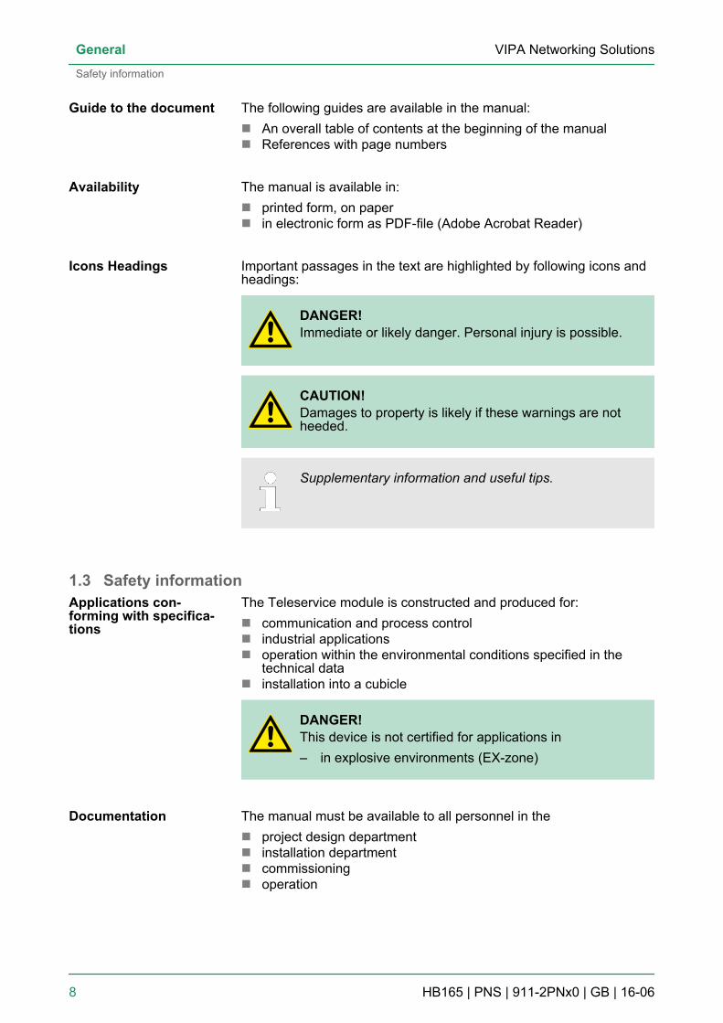
Important passages in the text are highlighted by following icons andheadings:
DANGER!Immediate or likely danger. Personal injury is possible.
CAUTION!Damages to property is likely if these warnings are notheeded.
Supplementary information and useful tips.
1.3 Safety informationThe Teleservice module is constructed and produced for:n communication and process controln industrial applicationsn operation within the environmental conditions specified in the
technical datan installation into a cubicle
DANGER!This device is not certified for applications in– in explosive environments (EX-zone)
The manual must be available to all personnel in then project design departmentn installation departmentn commissioningn operation
Guide to the document
Availability
Icons Headings
Applications con-forming with specifica-tions
Documentation
VIPA Networking SolutionsGeneral
Safety information
HB165 | PNS | 911-2PNx0 | GB | 16-06 8
CAUTION!The following conditions must be met before using orcommissioning the components described in thismanual:– Hardware modifications to the process control system
should only be carried out when the system has beendisconnected from power!
– Installation and hardware modifications only by prop-erly trained personnel.
– The national rules and regulations of the respectivecountry must be satisfied (installation, safety, EMC ...)
National rules and regulations apply to the disposal of the unit!Disposal
VIPA Networking Solutions General
Safety information
HB165 | PNS | 911-2PNx0 | GB | 16-06 9
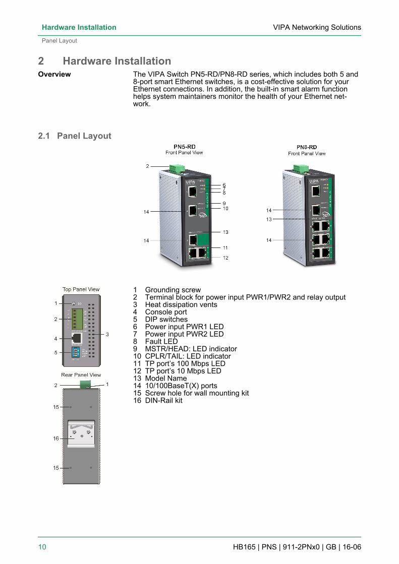
2 Hardware InstallationThe VIPA Switch PN5-RD/PN8-RD series, which includes both 5 and8-port smart Ethernet switches, is a cost-effective solution for yourEthernet connections. In addition, the built-in smart alarm functionhelps system maintainers monitor the health of your Ethernet net-work.
2.1 Panel Layout
1 Grounding screw2 Terminal block for power input PWR1/PWR2 and relay output3 Heat dissipation vents4 Console port5 DIP switches6 Power input PWR1 LED7 Power input PWR2 LED8 Fault LED9 MSTR/HEAD: LED indicator10 CPLR/TAIL: LED indicator11 TP port’s 100 Mbps LED12 TP port’s 10 Mbps LED13 Model Name14 10/100BaseT(X) ports15 Screw hole for wall mounting kit16 DIN-Rail kit
Overview
VIPA Networking SolutionsHardware Installation
Panel Layout
HB165 | PNS | 911-2PNx0 | GB | 16-06 10
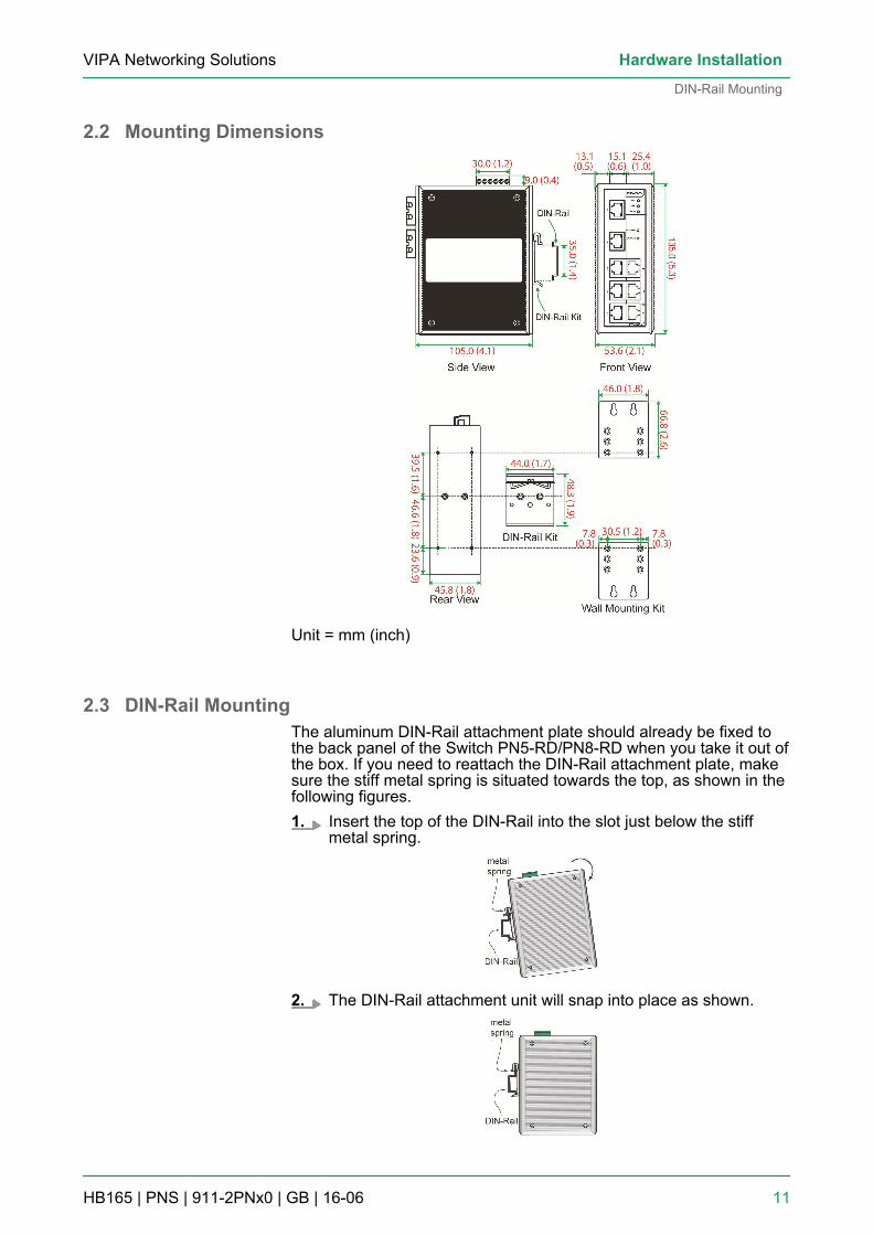
2.2 Mounting Dimensions
Unit = mm (inch)
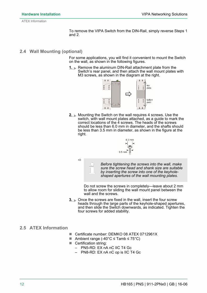
2.3 DIN-Rail MountingThe aluminum DIN-Rail attachment plate should already be fixed tothe back panel of the Switch PN5-RD/PN8-RD when you take it out ofthe box. If you need to reattach the DIN-Rail attachment plate, makesure the stiff metal spring is situated towards the top, as shown in thefollowing figures.1. Insert the top of the DIN-Rail into the slot just below the stiff
metal spring.
2. The DIN-Rail attachment unit will snap into place as shown.
VIPA Networking Solutions Hardware Installation
DIN-Rail Mounting
HB165 | PNS | 911-2PNx0 | GB | 16-06 11
To remove the VIPA Switch from the DIN-Rail, simply reverse Steps 1and 2.
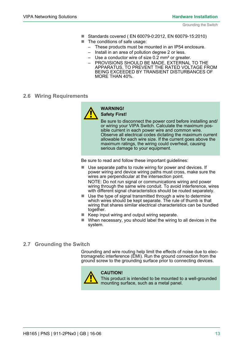
2.4 Wall Mounting (optional)For some applications, you will find it convenient to mount the Switchon the wall, as shown in the following figures.1. Remove the aluminum DIN-Rail attachment plate from the
Switch’s rear panel, and then attach the wall mount plates withM3 screws, as shown in the diagram at the right.
2. Mounting the Switch on the wall requires 4 screws. Use theswitch, with wall mount plates attached, as a guide to mark thecorrect locations of the 4 screws. The heads of the screwsshould be less than 6.0 mm in diameter, and the shafts shouldbe less than 3.5 mm in diameter, as shown in the figure at theright.
ðBefore tightening the screws into the wall, makesure the screw head and shank size are suitableby inserting the screw into one of the keyhole-shaped apertures of the wall mounting plates.
Do not screw the screws in completely—leave about 2 mmto allow room for sliding the wall mount panel between thewall and the screws.
3. Once the screws are fixed in the wall, insert the four screwheads through the large parts of the keyhole-shaped apertures,and then slide the Switch downwards, as indicated. Tighten thefour screws for added stability.
2.5 ATEX Informationn Certificate number: DEMKO 08 ATEX 0712961Xn Ambient range (-40°C ≤ Tamb ≤ 75°C)n Certification string:
– PN5-RD: EX nA nC IIC T4 Gc– PN8-RD: EX nA nC op is IIC T4 Gc
VIPA Networking SolutionsHardware Installation
ATEX Information
HB165 | PNS | 911-2PNx0 | GB | 16-06 12
n Standards covered ( EN 60079-0:2012, EN 60079-15:2010)n The conditions of safe usage:
– These products must be mounted in an IP54 enclosure.– Install in an area of pollution degree 2 or less.– Use a conductor wire of size 0.2 mm² or greater.– PROVISIONS SHOULD BE MADE, EXTERNAL TO THE
APPARATUS, TO PREVENT THE RATED VOLTAGE FROMBEING EXCEEDED BY TRANSIENT DISTURBANCES OFMORE THAN 40%.
2.6 Wiring Requirements
WARNING!Safety First!Be sure to disconnect the power cord before installing and/or wiring your VIPA Switch. Calculate the maximum pos-sible current in each power wire and common wire.Observe all electrical codes dictating the maximum currentallowable for each wire size. If the current goes above themaximum ratings, the wiring could overheat, causingserious damage to your equipment.
Be sure to read and follow these important guidelines:n Use separate paths to route wiring for power and devices. If
power wiring and device wiring paths must cross, make sure thewires are perpendicular at the intersection point.NOTE: Do not run signal or communications wiring and powerwiring through the same wire conduit. To avoid interference, wireswith different signal characteristics should be routed separately.
n Use the type of signal transmitted through a wire to determinewhich wires should be kept separate. The rule of thumb is thatwiring that shares similar electrical characteristics can be bundledtogether.
n Keep input wiring and output wiring separate.n When necessary, you should label the wiring to all devices in the
system.
2.7 Grounding the SwitchGrounding and wire routing help limit the effects of noise due to elec-tromagnetic interference (EMI). Run the ground connection from theground screw to the grounding surface prior to connecting devices.
CAUTION!This product is intended to be mounted to a well-groundedmounting surface, such as a metal panel.
VIPA Networking Solutions Hardware Installation
Grounding the Switch
HB165 | PNS | 911-2PNx0 | GB | 16-06 13
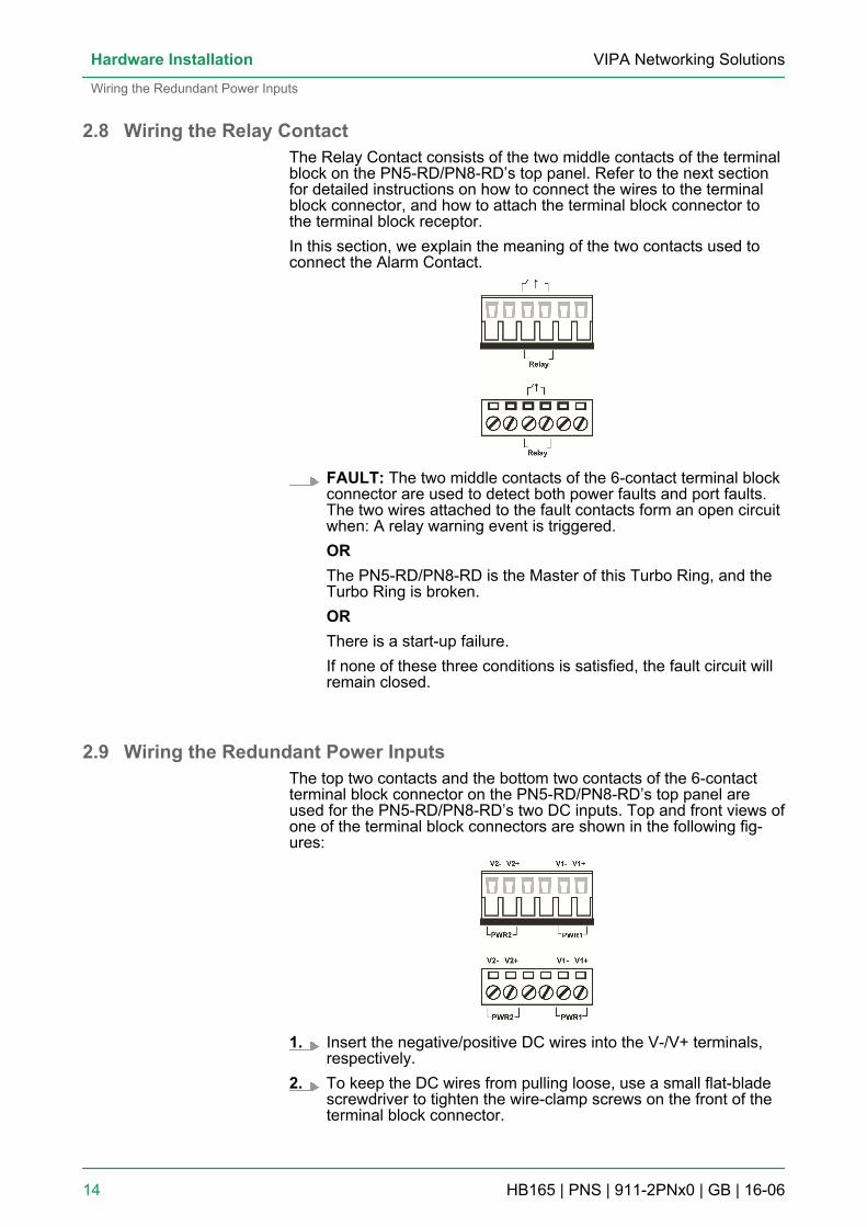
2.8 Wiring the Relay ContactThe Relay Contact consists of the two middle contacts of the terminalblock on the PN5-RD/PN8-RD’s top panel. Refer to the next sectionfor detailed instructions on how to connect the wires to the terminalblock connector, and how to attach the terminal block connector tothe terminal block receptor.In this section, we explain the meaning of the two contacts used toconnect the Alarm Contact.
FAULT: The two middle contacts of the 6-contact terminal blockconnector are used to detect both power faults and port faults.The two wires attached to the fault contacts form an open circuitwhen: A relay warning event is triggered.ORThe PN5-RD/PN8-RD is the Master of this Turbo Ring, and theTurbo Ring is broken.ORThere is a start-up failure.If none of these three conditions is satisfied, the fault circuit willremain closed.
2.9 Wiring the Redundant Power InputsThe top two contacts and the bottom two contacts of the 6-contactterminal block connector on the PN5-RD/PN8-RD’s top panel areused for the PN5-RD/PN8-RD’s two DC inputs. Top and front views ofone of the terminal block connectors are shown in the following fig-ures:
1. Insert the negative/positive DC wires into the V-/V+ terminals,respectively.
2. To keep the DC wires from pulling loose, use a small flat-bladescrewdriver to tighten the wire-clamp screws on the front of theterminal block connector.
VIPA Networking SolutionsHardware Installation
Wiring the Redundant Power Inputs
HB165 | PNS | 911-2PNx0 | GB | 16-06 14
3. Insert the plastic terminal block connector prongs into the ter-minal block receptor, which is located on the Switch’s top panel.ð
CAUTION!Before connecting the PN5-RD/PN8-RD to theDC power inputs, make sure the DC powersource voltage is stable.
2.10 Communication ConnectionsPN8-RD models have 5, 6, or 8 10/100BaseT(X) Ethernet ports, and3, 2, or 0 (zero) 100BaseFX (SC/ST-type connector) fiber ports. PN5-RD models have 3 or 5 10/100BaseT(X) Ethernet ports, and 2 or 0(zero) 100 BaseFX (SC/ST-type connector) fiber ports.
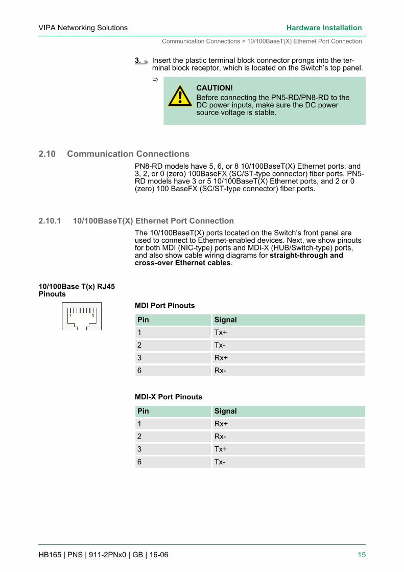
2.10.1 10/100BaseT(X) Ethernet Port ConnectionThe 10/100BaseT(X) ports located on the Switch’s front panel areused to connect to Ethernet-enabled devices. Next, we show pinoutsfor both MDI (NIC-type) ports and MDI-X (HUB/Switch-type) ports,and also show cable wiring diagrams for straight-through andcross-over Ethernet cables.
MDI Port Pinouts
Pin Signal1 Tx+
2 Tx-
3 Rx+
6 Rx-
MDI-X Port Pinouts
Pin Signal1 Rx+
2 Rx-
3 Tx+
6 Tx-
10/100Base T(x) RJ45Pinouts
VIPA Networking Solutions Hardware Installation
Communication Connections > 10/100BaseT(X) Ethernet Port Connection
HB165 | PNS | 911-2PNx0 | GB | 16-06 15
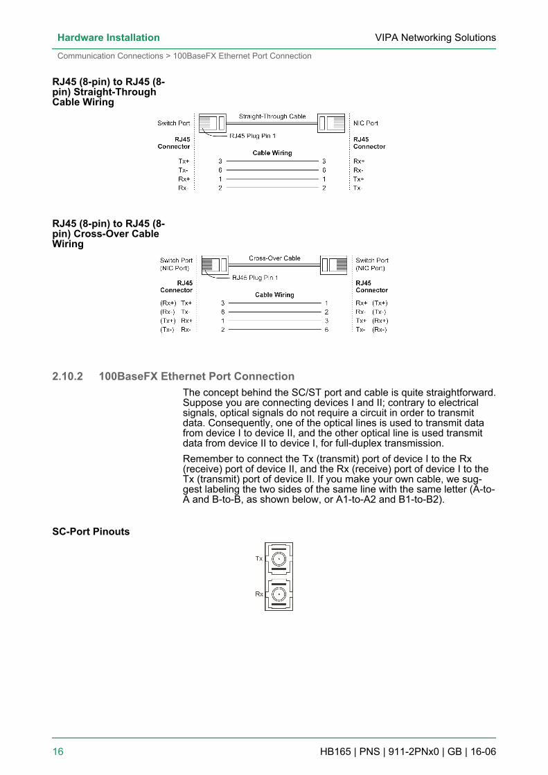
2.10.2 100BaseFX Ethernet Port ConnectionThe concept behind the SC/ST port and cable is quite straightforward.Suppose you are connecting devices I and II; contrary to electricalsignals, optical signals do not require a circuit in order to transmitdata. Consequently, one of the optical lines is used to transmit datafrom device I to device II, and the other optical line is used transmitdata from device II to device I, for full-duplex transmission.Remember to connect the Tx (transmit) port of device I to the Rx(receive) port of device II, and the Rx (receive) port of device I to theTx (transmit) port of device II. If you make your own cable, we sug-gest labeling the two sides of the same line with the same letter (A-to-A and B-to-B, as shown below, or A1-to-A2 and B1-to-B2).
RJ45 (8-pin) to RJ45 (8-pin) Straight-ThroughCable Wiring
RJ45 (8-pin) to RJ45 (8-pin) Cross-Over CableWiring
SC-Port Pinouts
VIPA Networking SolutionsHardware Installation
Communication Connections > 100BaseFX Ethernet Port Connection
HB165 | PNS | 911-2PNx0 | GB | 16-06 16
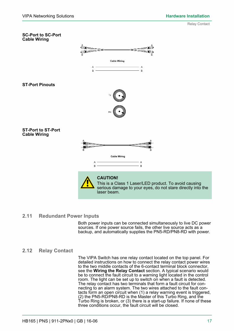
CAUTION!This is a Class 1 Laser/LED product. To avoid causingserious damage to your eyes, do not stare directly into thelaser beam.
2.11 Redundant Power InputsBoth power inputs can be connected simultaneously to live DC powersources. If one power source fails, the other live source acts as abackup, and automatically supplies the PN5-RD/PN8-RD with power.
2.12 Relay ContactThe VIPA Switch has one relay contact located on the top panel. Fordetailed instructions on how to connect the relay contact power wiresto the two middle contacts of the 6-contact terminal block connector,see the Wiring the Relay Contact section. A typical scenario wouldbe to connect the fault circuit to a warning light located in the controlroom. The light can be set up to switch on when a fault is detected.The relay contact has two terminals that form a fault circuit for con-necting to an alarm system. The two wires attached to the fault con-tacts form an open circuit when (1) a relay warning event is triggered,(2) the PN5-RD/PN8-RD is the Master of this Turbo Ring, and theTurbo Ring is broken, or (3) there is a start-up failure. If none of thesethree conditions occur, the fault circuit will be closed.
SC-Port to SC-PortCable Wiring
ST-Port Pinouts
ST-Port to ST-PortCable Wiring
VIPA Networking Solutions Hardware Installation
Relay Contact
HB165 | PNS | 911-2PNx0 | GB | 16-06 17
2.13 Turbo Ring DIP Switch SettingsPN5-RD/PN8-RD series switches are plug-and-play managed redun-dant Ethernet switches. The proprietary Turbo Ring protocol wasdeveloped by VIPA to provide better network reliability and fasterrecovery time. VIPA Turbo Ring’s recovery time is less than 300 ms(Turbo Ring) or 20 ms (Turbo Ring V2) —compared to a 3 to 5-minute recovery time for commercial switches—decreasing the pos-sible loss caused by network failures in an industrial setting. Thereare 4 Hardware DIP Switches for Turbo Ring on the top panel of thePN5-RD/PN8-RD that can be used to set up the Turbo Ring easilywithin seconds. If you do not want to use a hardware DIP switch toset up Turbo Ring, you can use a web browser, Telnet, or console todisable this function.
Refer to the Turbo Ring DIP Switch section and UsingCommunication Redundancy section in the user’smanual for detailed information about the settings andusage of Turbo Ring and Turbo Ring V2.
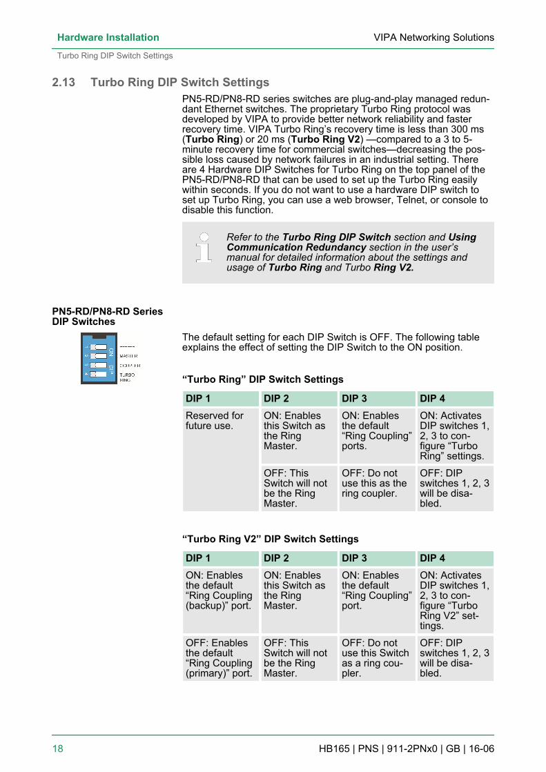
The default setting for each DIP Switch is OFF. The following tableexplains the effect of setting the DIP Switch to the ON position.
“Turbo Ring” DIP Switch Settings
DIP 1 DIP 2 DIP 3 DIP 4Reserved forfuture use.
ON: Enablesthis Switch asthe RingMaster.
ON: Enablesthe default“Ring Coupling”ports.
ON: ActivatesDIP switches 1,2, 3 to con-figure “TurboRing” settings.
OFF: ThisSwitch will notbe the RingMaster.
OFF: Do notuse this as thering coupler.
OFF: DIPswitches 1, 2, 3will be disa-bled.
“Turbo Ring V2” DIP Switch Settings
DIP 1 DIP 2 DIP 3 DIP 4ON: Enablesthe default“Ring Coupling(backup)” port.
ON: Enablesthis Switch asthe RingMaster.
ON: Enablesthe default“Ring Coupling”port.
ON: ActivatesDIP switches 1,2, 3 to con-figure “TurboRing V2” set-tings.
OFF: Enablesthe default“Ring Coupling(primary)” port.
OFF: ThisSwitch will notbe the RingMaster.
OFF: Do notuse this Switchas a ring cou-pler.
OFF: DIPswitches 1, 2, 3will be disa-bled.
PN5-RD/PN8-RD SeriesDIP Switches
VIPA Networking SolutionsHardware Installation
Turbo Ring DIP Switch Settings
HB165 | PNS | 911-2PNx0 | GB | 16-06 18
If you do not enable any of the PN5-RD/PN8-RD switchesto be the Ring Master, the Turbo Ring protocol will auto-matically choose the PN5-RD/PN8-RD with the smallestMAC address range to be the Ring Master. If you acciden-tally enable more than one PN5-RD/PN8-RD to be theRing Master, these PN5-RD/PN8-RD switches will auto-negotiate to determine which switch will be the RingMaster.
To switch on the Master or Coupler functions of the DIPswitch, you need to enable the Turbo Ring Pole first.
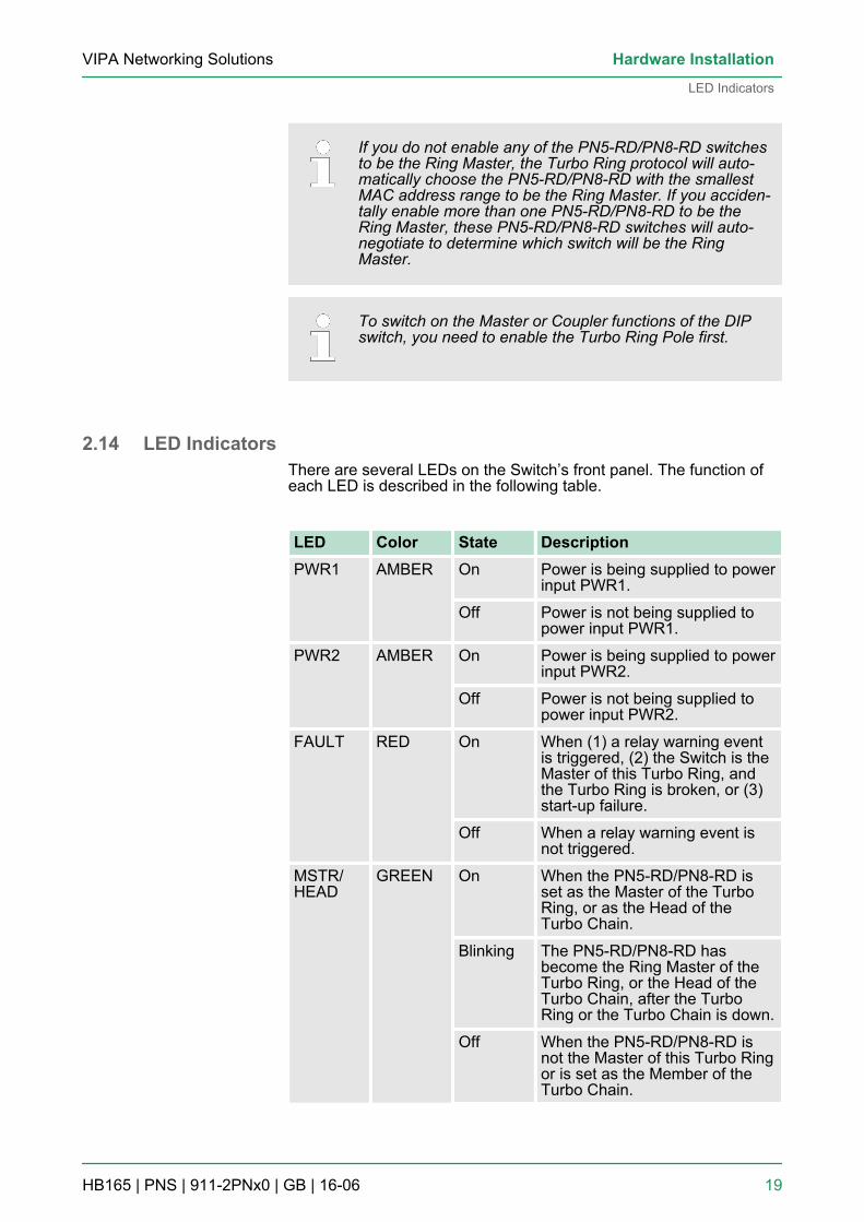
2.14 LED IndicatorsThere are several LEDs on the Switch’s front panel. The function ofeach LED is described in the following table.
LED Color State DescriptionPWR1 AMBER On Power is being supplied to power
input PWR1.
Off Power is not being supplied topower input PWR1.
PWR2 AMBER On Power is being supplied to powerinput PWR2.
Off Power is not being supplied topower input PWR2.
FAULT RED On When (1) a relay warning eventis triggered, (2) the Switch is theMaster of this Turbo Ring, andthe Turbo Ring is broken, or (3)start-up failure.
Off When a relay warning event isnot triggered.
MSTR/HEAD
GREEN On When the PN5-RD/PN8-RD isset as the Master of the TurboRing, or as the Head of theTurbo Chain.
Blinking The PN5-RD/PN8-RD hasbecome the Ring Master of theTurbo Ring, or the Head of theTurbo Chain, after the TurboRing or the Turbo Chain is down.
Off When the PN5-RD/PN8-RD isnot the Master of this Turbo Ringor is set as the Member of theTurbo Chain.
VIPA Networking Solutions Hardware Installation
LED Indicators
HB165 | PNS | 911-2PNx0 | GB | 16-06 19
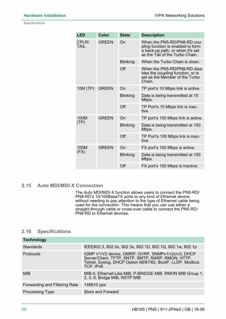
LED Color State DescriptionCPLR/TAIL
GREEN On When the PN5-RD/PN8-RD cou-pling function is enabled to forma back-up path, or when it's setas the Tail of the Turbo Chain.
Blinking When the Turbo Chain is down.
Off When the PN5-RD/PN8-RD disa-bles the coupling function, or isset as the Member of the TurboChain.
10M (TP) GREEN On TP port’s 10 Mbps link is active.
Blinking Data is being transmitted at 10Mbps.
Off TP Port’s 10 Mbps link is inac-tive.
100M(TP)
GREEN On TP port’s 100 Mbps link is active.
Blinking Data is being transmitted at 100Mbps.
Off TP Port’s 100 Mbps link is inac-tive.
100M(FX)
GREEN On FX port’s 100 Mbps is active.
Blinking Data is being transmitted at 100Mbps.
Off FX port’s 100 Mbps is inactive.
2.15 Auto MDI/MDI-X ConnectionThe Auto MDI/MDI-X function allows users to connect the PN5-RD/PN8-RD’s 10/100BaseTX ports to any kind of Ethernet device,without needing to pay attention to the type of Ethernet cable beingused for the connection. This means that you can use either astraight-through cable or cross-over cable to connect the PN5-RD/PN8-RD to Ethernet devices.
2.16 SpecificationsTechnologyStandards IEEE802.3, 802.3u, 802.3x, 802.1D, 802.1Q, 802.1w, 802.1p
Protocols IGMP V1/V2 device, GMRP, GVRP, SNMPv1/v2c/v3, DHCPServer/Client, TFTP, SNTP, SMTP, RARP, RMON, HTTP,Telnet, Syslog, DHCP Option 66/67/82, BootP, LLDP, ModbusTCP, IPv6
MIB MIB-II, Ethernet-Like MIB, P-BRIDGE MIB, RMON MIB Group 1,2, 3, 9, Bridge MIB, RSTP MIB
Forwarding and Filtering Rate 148810 pps
Processing Type Store and Forward
VIPA Networking SolutionsHardware Installation
Specifications
HB165 | PNS | 911-2PNx0 | GB | 16-06 20
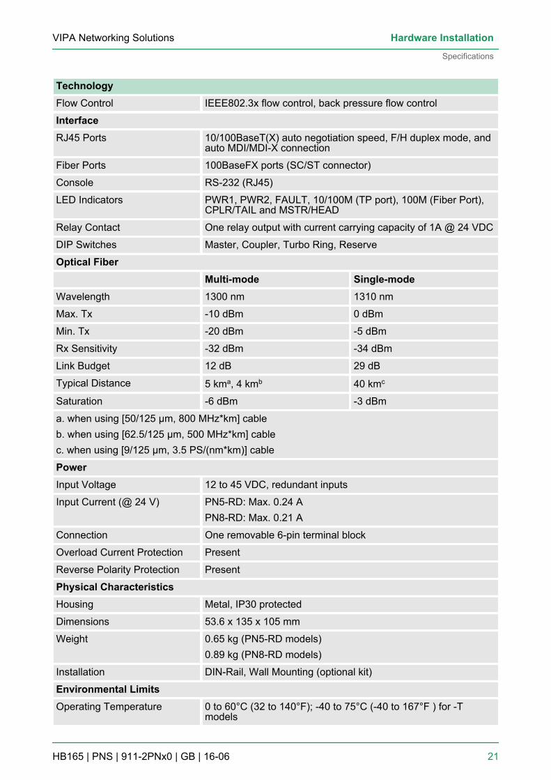
TechnologyFlow Control IEEE802.3x flow control, back pressure flow control
InterfaceRJ45 Ports 10/100BaseT(X) auto negotiation speed, F/H duplex mode, and
auto MDI/MDI-X connection
Fiber Ports 100BaseFX ports (SC/ST connector)
Console RS-232 (RJ45)
LED Indicators PWR1, PWR2, FAULT, 10/100M (TP port), 100M (Fiber Port),CPLR/TAIL and MSTR/HEAD
Relay Contact One relay output with current carrying capacity of 1A @ 24 VDC
DIP Switches Master, Coupler, Turbo Ring, Reserve
Optical Fiber Multi-mode Single-modeWavelength 1300 nm 1310 nm
Max. Tx -10 dBm 0 dBm
Min. Tx -20 dBm -5 dBm
Rx Sensitivity -32 dBm -34 dBm
Link Budget 12 dB 29 dB
Typical Distance 5 kma, 4 kmb 40 kmc
Saturation -6 dBm -3 dBm
a. when using [50/125 μm, 800 MHz*km] cableb. when using [62.5/125 μm, 500 MHz*km] cablec. when using [9/125 μm, 3.5 PS/(nm*km)] cable
PowerInput Voltage 12 to 45 VDC, redundant inputs
Input Current (@ 24 V) PN5-RD: Max. 0.24 APN8-RD: Max. 0.21 A
Connection One removable 6-pin terminal block
Overload Current Protection Present
Reverse Polarity Protection Present
Physical CharacteristicsHousing Metal, IP30 protected
Dimensions 53.6 x 135 x 105 mm
Weight 0.65 kg (PN5-RD models)0.89 kg (PN8-RD models)
Installation DIN-Rail, Wall Mounting (optional kit)
Environmental LimitsOperating Temperature 0 to 60°C (32 to 140°F); -40 to 75°C (-40 to 167°F ) for -T
models
VIPA Networking Solutions Hardware Installation
Specifications
HB165 | PNS | 911-2PNx0 | GB | 16-06 21
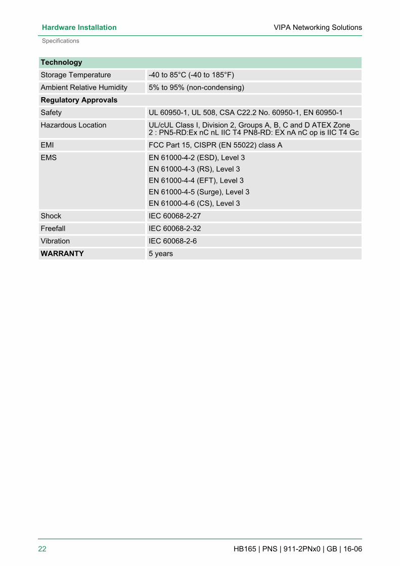
TechnologyStorage Temperature -40 to 85°C (-40 to 185°F)
Ambient Relative Humidity 5% to 95% (non-condensing)
Regulatory ApprovalsSafety UL 60950-1, UL 508, CSA C22.2 No. 60950-1, EN 60950-1
Hazardous Location UL/cUL Class I, Division 2, Groups A, B, C and D ATEX Zone2 : PN5-RD:Ex nC nL IIC T4 PN8-RD: EX nA nC op is IIC T4 Gc
EMI FCC Part 15, CISPR (EN 55022) class A
EMS EN 61000-4-2 (ESD), Level 3EN 61000-4-3 (RS), Level 3EN 61000-4-4 (EFT), Level 3EN 61000-4-5 (Surge), Level 3EN 61000-4-6 (CS), Level 3
Shock IEC 60068-2-27
Freefall IEC 60068-2-32
Vibration IEC 60068-2-6
WARRANTY 5 years
VIPA Networking SolutionsHardware Installation
Specifications
HB165 | PNS | 911-2PNx0 | GB | 16-06 22
3 Getting StartedIn this chapter we explain how to install a VIPA switch for the firsttime. There are three ways to access the VIPA switch’s configurationsettings: serial console, Telnet console, or web console. If you do notknow the VIPA switch’s IP address, you can open the serial consoleby connecting the VIPA switch to a PC’s COM port with a short serialcable. You can open the Telnet or web console over an Ethernet LANor over the Internet. The following topics are covered in this chapter:n Serial Console Configuration (115200, None, 8, 1, VT100)n Configuration by Telnet Consolen Configuration by Web Browsern Disabling Telnet and Browser Access
3.1 Serial Console Configuration (115200, None, 8, 1, VT100)
– You cannot connect to the serial and Telnet console atthe same time.
– You can connect to the web console and another con-sole (serial or Telnet) at the same time. However, westrongly recommend that you do NOT do so. Followingthis advice will allow you to maintain better control overthe VIPA switch’s configuration.
We recommend using PComm Terminal Emulator whenopening the serial console. This software can be down-loaded free of charge from the VIPA website.
VIPA Networking Solutions Getting Started
Serial Console Configuration (115200, None, 8, 1, VT100)
HB165 | PNS | 911-2PNx0 | GB | 16-06 23
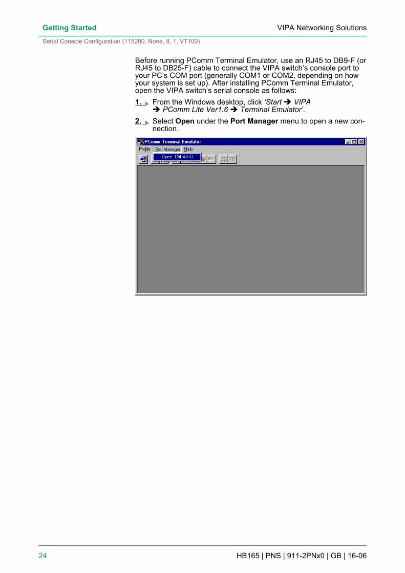
Before running PComm Terminal Emulator, use an RJ45 to DB9-F (orRJ45 to DB25-F) cable to connect the VIPA switch’s console port toyour PC’s COM port (generally COM1 or COM2, depending on howyour system is set up). After installing PComm Terminal Emulator,open the VIPA switch’s serial console as follows:1. From the Windows desktop, click ‘Start è VIPA
è PComm Lite Ver1.6 è Terminal Emulator’.2. Select Open under the Port Manager menu to open a new con-
nection.
VIPA Networking SolutionsGetting Started
Serial Console Configuration (115200, None, 8, 1, VT100)
HB165 | PNS | 911-2PNx0 | GB | 16-06 24
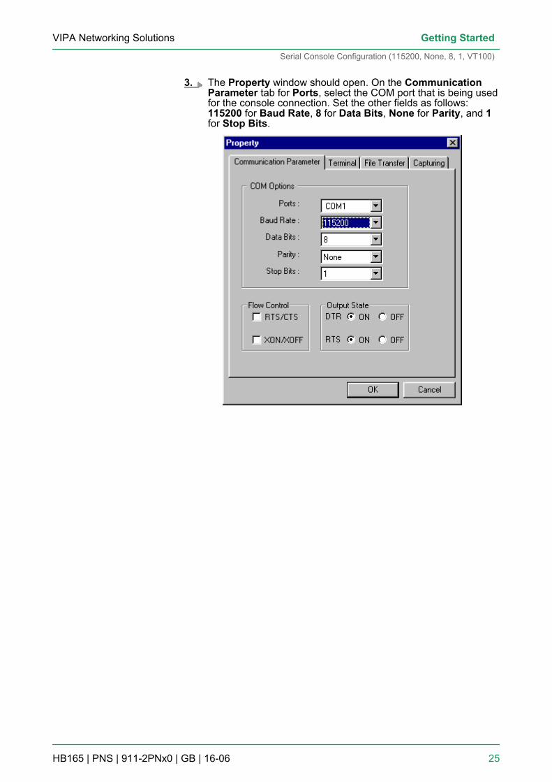
3. The Property window should open. On the CommunicationParameter tab for Ports, select the COM port that is being usedfor the console connection. Set the other fields as follows:115200 for Baud Rate, 8 for Data Bits, None for Parity, and 1for Stop Bits.
VIPA Networking Solutions Getting Started
Serial Console Configuration (115200, None, 8, 1, VT100)
HB165 | PNS | 911-2PNx0 | GB | 16-06 25
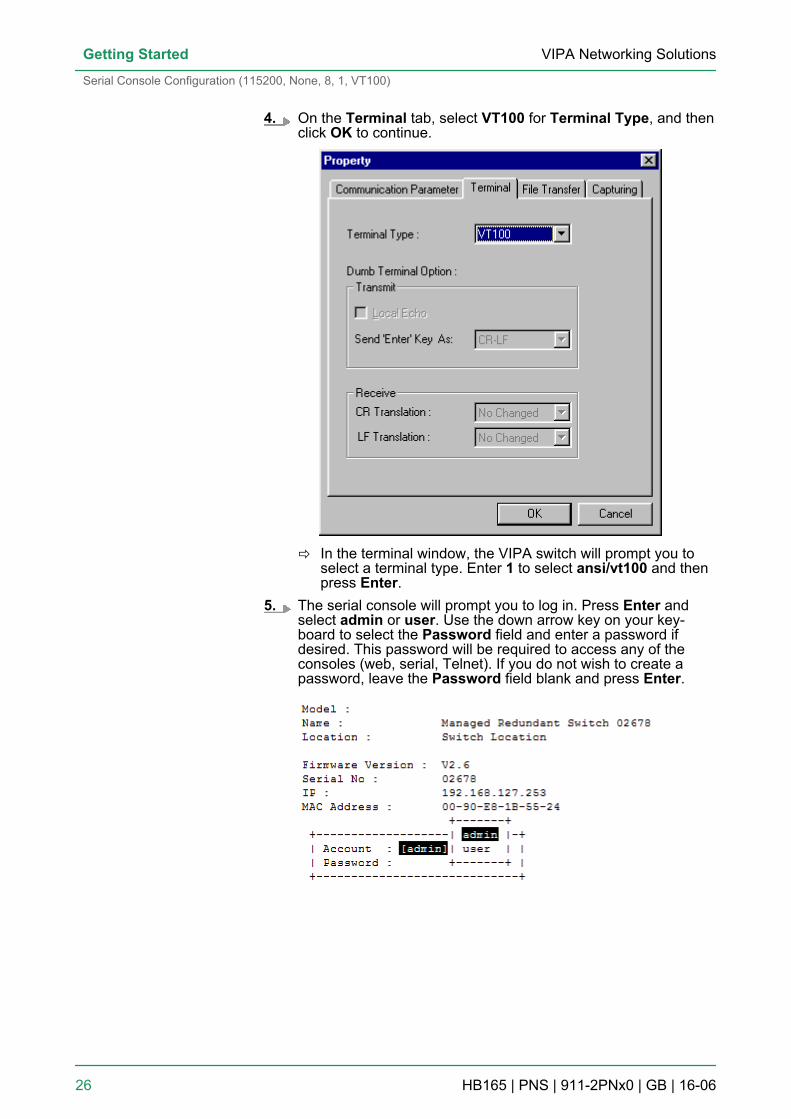
4. On the Terminal tab, select VT100 for Terminal Type, and thenclick OK to continue.
ð In the terminal window, the VIPA switch will prompt you toselect a terminal type. Enter 1 to select ansi/vt100 and thenpress Enter.
5. The serial console will prompt you to log in. Press Enter andselect admin or user. Use the down arrow key on your key-board to select the Password field and enter a password ifdesired. This password will be required to access any of theconsoles (web, serial, Telnet). If you do not wish to create apassword, leave the Password field blank and press Enter.
VIPA Networking SolutionsGetting Started
Serial Console Configuration (115200, None, 8, 1, VT100)
HB165 | PNS | 911-2PNx0 | GB | 16-06 26
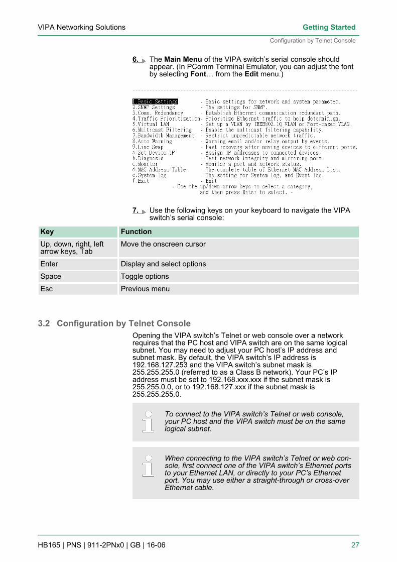
6. The Main Menu of the VIPA switch’s serial console shouldappear. (In PComm Terminal Emulator, you can adjust the fontby selecting Font… from the Edit menu.)
7. Use the following keys on your keyboard to navigate the VIPAswitch’s serial console:
Key FunctionUp, down, right, leftarrow keys, Tab
Move the onscreen cursor
Enter Display and select options
Space Toggle options
Esc Previous menu
3.2 Configuration by Telnet ConsoleOpening the VIPA switch’s Telnet or web console over a networkrequires that the PC host and VIPA switch are on the same logicalsubnet. You may need to adjust your PC host’s IP address andsubnet mask. By default, the VIPA switch’s IP address is192.168.127.253 and the VIPA switch’s subnet mask is255.255.255.0 (referred to as a Class B network). Your PC’s IPaddress must be set to 192.168.xxx.xxx if the subnet mask is255.255.0.0, or to 192.168.127.xxx if the subnet mask is255.255.255.0.
To connect to the VIPA switch’s Telnet or web console,your PC host and the VIPA switch must be on the samelogical subnet.
When connecting to the VIPA switch’s Telnet or web con-sole, first connect one of the VIPA switch’s Ethernet portsto your Ethernet LAN, or directly to your PC’s Ethernetport. You may use either a straight-through or cross-overEthernet cable.
VIPA Networking Solutions Getting Started
Configuration by Telnet Console
HB165 | PNS | 911-2PNx0 | GB | 16-06 27
The VIPA switch’s default IP address is 192.168.127.253.
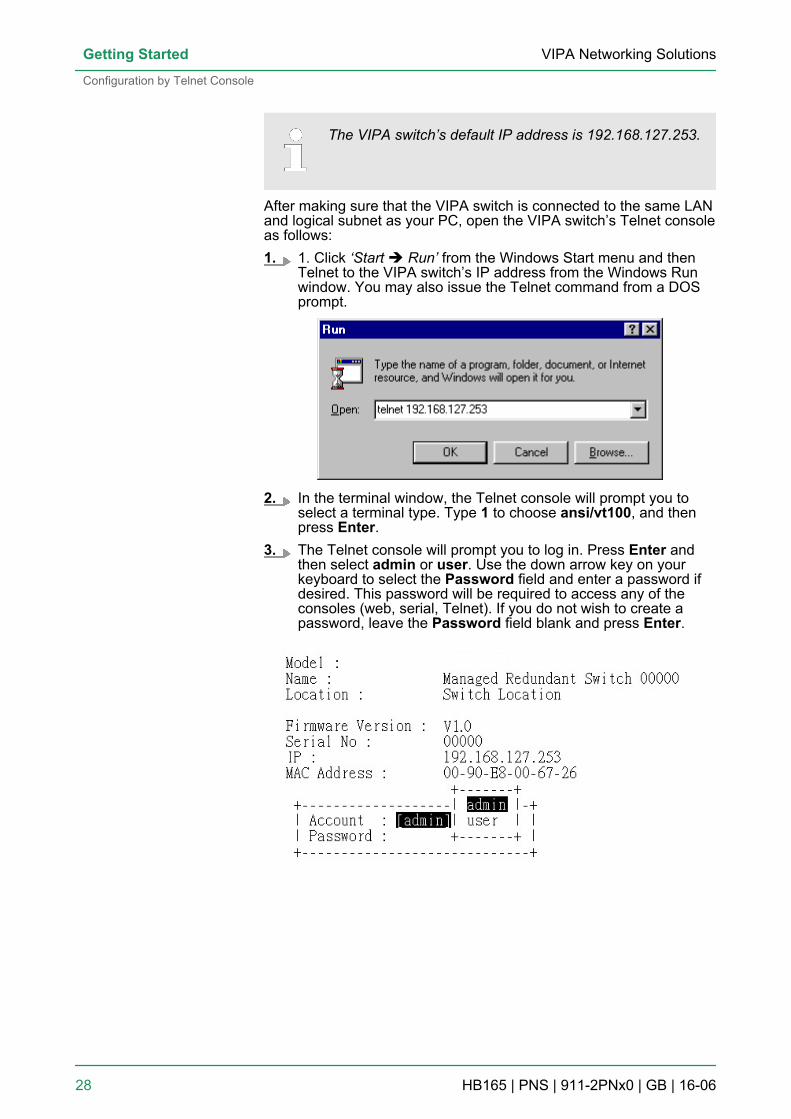
After making sure that the VIPA switch is connected to the same LANand logical subnet as your PC, open the VIPA switch’s Telnet consoleas follows:1. 1. Click ‘Start è Run’ from the Windows Start menu and then
Telnet to the VIPA switch’s IP address from the Windows Runwindow. You may also issue the Telnet command from a DOSprompt.
2. In the terminal window, the Telnet console will prompt you toselect a terminal type. Type 1 to choose ansi/vt100, and thenpress Enter.
3. The Telnet console will prompt you to log in. Press Enter andthen select admin or user. Use the down arrow key on yourkeyboard to select the Password field and enter a password ifdesired. This password will be required to access any of theconsoles (web, serial, Telnet). If you do not wish to create apassword, leave the Password field blank and press Enter.
VIPA Networking SolutionsGetting Started
Configuration by Telnet Console
HB165 | PNS | 911-2PNx0 | GB | 16-06 28
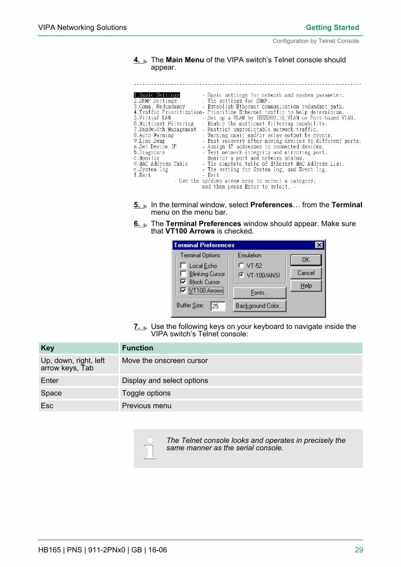
4. The Main Menu of the VIPA switch’s Telnet console shouldappear.
5. In the terminal window, select Preferences… from the Terminalmenu on the menu bar.
6. The Terminal Preferences window should appear. Make surethat VT100 Arrows is checked.
7. Use the following keys on your keyboard to navigate inside theVIPA switch’s Telnet console:
Key FunctionUp, down, right, leftarrow keys, Tab
Move the onscreen cursor
Enter Display and select options
Space Toggle options
Esc Previous menu
The Telnet console looks and operates in precisely thesame manner as the serial console.
VIPA Networking Solutions Getting Started
Configuration by Telnet Console
HB165 | PNS | 911-2PNx0 | GB | 16-06 29
3.3 Configuration by Web BrowserThe VIPA switch’s web console is a convenient platform for modifyingthe configuration and accessing the built-in monitoring and networkadministration functions. You can open the VIPA switch’s web con-sole using a standard web browser, such as Internet Explorer.
To connect to the VIPA switch’s Telnet or web console,your PC host and the VIPA switch must be on the samelogical subnet.
If the VIPA switch is configured for other VLAN settings,you must make sure your PC host is on the managementVLAN.
When connecting to the VIPA switch’s Telnet or web con-sole, first connect one of the VIPA switch’s Ethernet portsto your Ethernet LAN, or directly to your PC’s Ethernetport. You may use either a straight-through or cross-overEthernet cable.
The VIPA switch’s default IP address is 192.168.127.253.
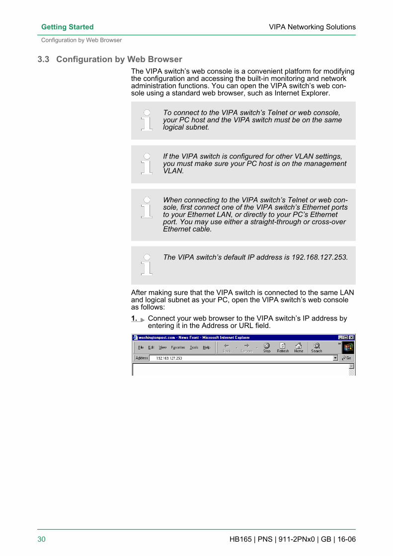
After making sure that the VIPA switch is connected to the same LANand logical subnet as your PC, open the VIPA switch’s web consoleas follows:1. Connect your web browser to the VIPA switch’s IP address by
entering it in the Address or URL field.
VIPA Networking SolutionsGetting Started
Configuration by Web Browser
HB165 | PNS | 911-2PNx0 | GB | 16-06 30
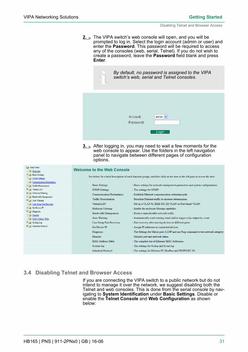
2. The VIPA switch’s web console will open, and you will beprompted to log in. Select the login account (admin or user) andenter the Password. This password will be required to accessany of the consoles (web, serial, Telnet). If you do not wish tocreate a password, leave the Password field blank and pressEnter.
By default, no password is assigned to the VIPAswitch’s web, serial and Telnet consoles.
3. After logging in, you may need to wait a few moments for theweb console to appear. Use the folders in the left navigationpanel to navigate between different pages of configurationoptions.
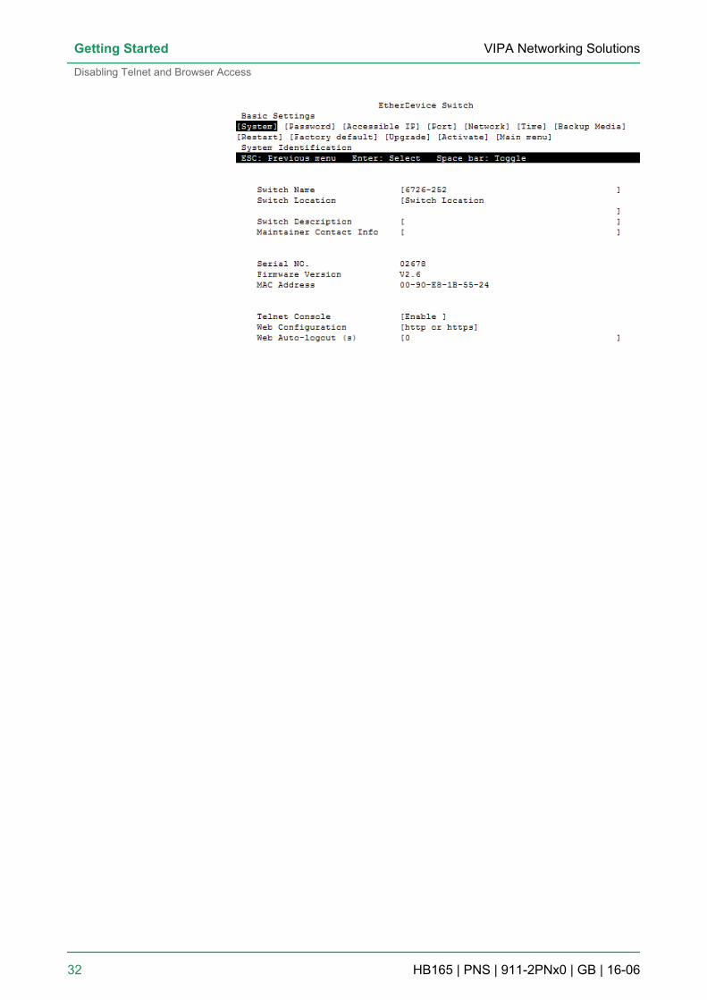
3.4 Disabling Telnet and Browser AccessIf you are connecting the VIPA switch to a public network but do notintend to manage it over the network, we suggest disabling both theTelnet and web consoles. This is done from the serial console by nav-igating to System Identification under Basic Settings. Disable orenable the Telnet Console and Web Configuration as shownbelow:
VIPA Networking Solutions Getting Started
Disabling Telnet and Browser Access
HB165 | PNS | 911-2PNx0 | GB | 16-06 31
VIPA Networking SolutionsGetting Started
Disabling Telnet and Browser Access
HB165 | PNS | 911-2PNx0 | GB | 16-06 32
4 Featured FunctionsIn this chapter, we explain how to access the VIPA switch’s variousconfiguration, monitoring, and administration functions. These func-tions can be accessed by serial, Telnet, or web console. The serialconsole can be used if you do not know the VIPA switch’s IP addressand requires that you connect the VIPA switch to a PC COM port.The Telnet and web consoles can be opened over an Ethernet LANor the Internet. The web console is the most user-friendly interface forconfiguring a VIPA switch. In this chapter, we use the web consoleinterface to introduce the functions. There are only a few differencesbetween the web console, serial console, and Telnet console.The following topics are covered in this chapter:n Configuring Basic Settingsn Loop Protectionn Configuring SNMPn Using Traffic Prioritizationn Using Virtual LANn Using Multicast Filteringn Using Bandwidth Managementn Using Auto Warningn Using Line-Swap-Fast-Recoveryn Using Set Device IPn Using Diagnosisn Using Monitorn Using the MAC Address Tablen Using Event Logn Using Syslog
4.1 Configuring Basic SettingsThe Basic Settings section includes the most common settingsrequired by administrators to maintain and control a VIPA switch.
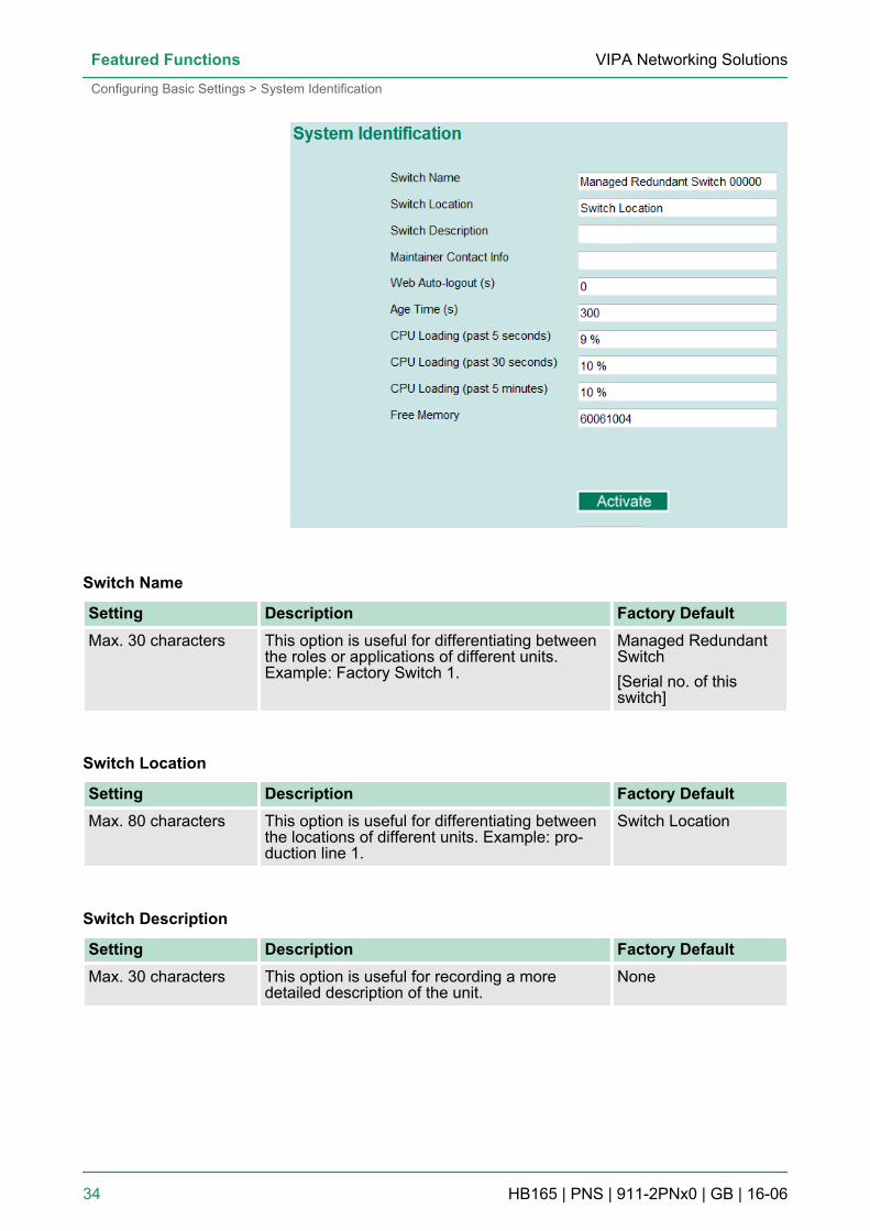
4.1.1 System IdentificationSystem Identification items are displayed at the top of the web con-sole and will be included in alarm emails. You can configure theSystem Identification items to make it easier to identify differentswitches that are connected to your network.
VIPA Networking Solutions Featured Functions
Configuring Basic Settings > System Identification
HB165 | PNS | 911-2PNx0 | GB | 16-06 33
Switch Name
Setting Description Factory DefaultMax. 30 characters This option is useful for differentiating between
the roles or applications of different units.Example: Factory Switch 1.
Managed RedundantSwitch[Serial no. of thisswitch]
Switch Location
Setting Description Factory DefaultMax. 80 characters This option is useful for differentiating between
the locations of different units. Example: pro-duction line 1.
Switch Location
Switch Description
Setting Description Factory DefaultMax. 30 characters This option is useful for recording a more
detailed description of the unit.None
VIPA Networking SolutionsFeatured Functions
Configuring Basic Settings > System Identification
HB165 | PNS | 911-2PNx0 | GB | 16-06 34
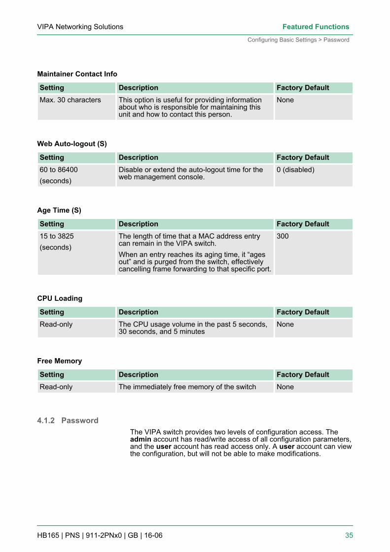
Maintainer Contact Info
Setting Description Factory DefaultMax. 30 characters This option is useful for providing information
about who is responsible for maintaining thisunit and how to contact this person.
None
Web Auto-logout (S)
Setting Description Factory Default60 to 86400(seconds)
Disable or extend the auto-logout time for theweb management console.
0 (disabled)
Age Time (S)
Setting Description Factory Default15 to 3825(seconds)
The length of time that a MAC address entrycan remain in the VIPA switch.When an entry reaches its aging time, it “agesout” and is purged from the switch, effectivelycancelling frame forwarding to that specific port.
300
CPU Loading
Setting Description Factory DefaultRead-only The CPU usage volume in the past 5 seconds,
30 seconds, and 5 minutesNone
Free Memory
Setting Description Factory DefaultRead-only The immediately free memory of the switch None
4.1.2 PasswordThe VIPA switch provides two levels of configuration access. Theadmin account has read/write access of all configuration parameters,and the user account has read access only. A user account can viewthe configuration, but will not be able to make modifications.
VIPA Networking Solutions Featured Functions
Configuring Basic Settings > Password
HB165 | PNS | 911-2PNx0 | GB | 16-06 35
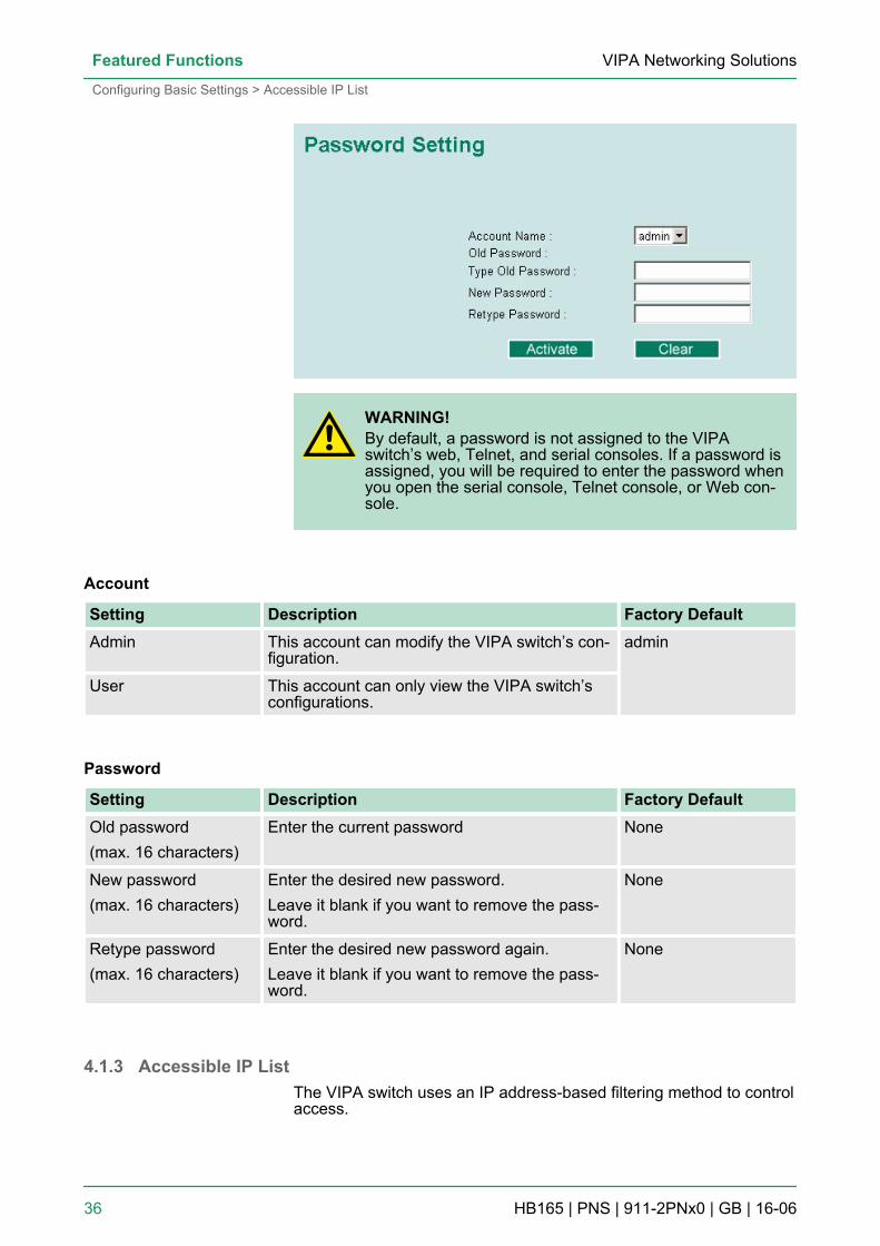
WARNING!By default, a password is not assigned to the VIPAswitch’s web, Telnet, and serial consoles. If a password isassigned, you will be required to enter the password whenyou open the serial console, Telnet console, or Web con-sole.
Account
Setting Description Factory DefaultAdmin This account can modify the VIPA switch’s con-
figuration.admin
User This account can only view the VIPA switch’sconfigurations.
Password
Setting Description Factory DefaultOld password(max. 16 characters)
Enter the current password None
New password(max. 16 characters)
Enter the desired new password.Leave it blank if you want to remove the pass-word.
None
Retype password(max. 16 characters)
Enter the desired new password again.Leave it blank if you want to remove the pass-word.
None
4.1.3 Accessible IP ListThe VIPA switch uses an IP address-based filtering method to controlaccess.
VIPA Networking SolutionsFeatured Functions
Configuring Basic Settings > Accessible IP List
HB165 | PNS | 911-2PNx0 | GB | 16-06 36
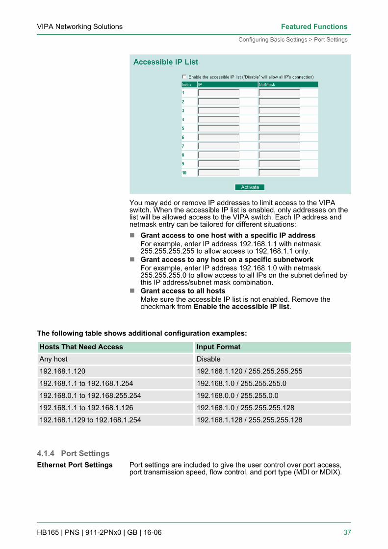
You may add or remove IP addresses to limit access to the VIPAswitch. When the accessible IP list is enabled, only addresses on thelist will be allowed access to the VIPA switch. Each IP address andnetmask entry can be tailored for different situations:n Grant access to one host with a specific IP address
For example, enter IP address 192.168.1.1 with netmask255.255.255.255 to allow access to 192.168.1.1 only.
n Grant access to any host on a specific subnetworkFor example, enter IP address 192.168.1.0 with netmask255.255.255.0 to allow access to all IPs on the subnet defined bythis IP address/subnet mask combination.
n Grant access to all hostsMake sure the accessible IP list is not enabled. Remove thecheckmark from Enable the accessible IP list.
The following table shows additional configuration examples:
Hosts That Need Access Input FormatAny host Disable
192.168.1.120 192.168.1.120 / 255.255.255.255
192.168.1.1 to 192.168.1.254 192.168.1.0 / 255.255.255.0
192.168.0.1 to 192.168.255.254 192.168.0.0 / 255.255.0.0
192.168.1.1 to 192.168.1.126 192.168.1.0 / 255.255.255.128
192.168.1.129 to 192.168.1.254 192.168.1.128 / 255.255.255.128
4.1.4 Port SettingsPort settings are included to give the user control over port access,port transmission speed, flow control, and port type (MDI or MDIX).
Ethernet Port Settings
VIPA Networking Solutions Featured Functions
Configuring Basic Settings > Port Settings
HB165 | PNS | 911-2PNx0 | GB | 16-06 37
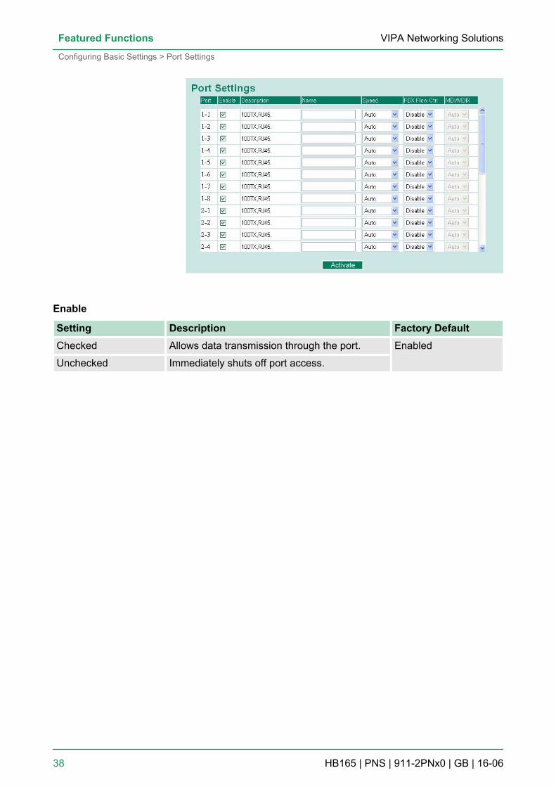
Enable
Setting Description Factory DefaultChecked Allows data transmission through the port. Enabled
Unchecked Immediately shuts off port access.
VIPA Networking SolutionsFeatured Functions
Configuring Basic Settings > Port Settings
HB165 | PNS | 911-2PNx0 | GB | 16-06 38
WARNING!If a connected device or sub-network is wreaking havoc onthe rest of the network, the Disable option underAdvanced Settings/Port gives the administrator a quickway to shut off access through this port immediately.
Description
Setting Description Factory DefaultMedia type Displays the media type for each module’s port N/A
Name
Setting Description Factory DefaultMax. 63 characters Specifies an alias for the port to help adminis-
trators differentiate between different ports.Example: PLC 1
None
Speed
Setting Description Factory DefaultAuto Allows the port to use the IEEE 802.3u protocol
to negotiate with connected devices.The port and connected devices will determinethe best speed for that connection.
Auto
1G-FullChoose one of these fixed speed options if theconnected Ethernet device has trouble auto-negotiating for line speed.
100M-Full
100M-Half
10M-Full
10M-Half
VIPA Networking Solutions Featured Functions
Configuring Basic Settings > Port Settings
HB165 | PNS | 911-2PNx0 | GB | 16-06 39
This setting enables or disables flow control for the port when theport’s Speed is set to Auto. The final result will be determined by theAuto process between the VIPA switch and connected devices.
Setting Description Factory DefaultEnable Enables flow control for this port when the
port’s Speed is set to Auto.Disabled
Disable Disables flow control for this port when theport’s Speed is set to Auto.
MDI/MDIX
Setting Description Factory DefaultAuto Allows the port to auto-detect the port type of
the connected Ethernet device and change theport type accordingly.
Auto
MDI Choose MDI or MDIX if the connected Ethernetdevice has trouble auto-negotiating for porttype.MDIX
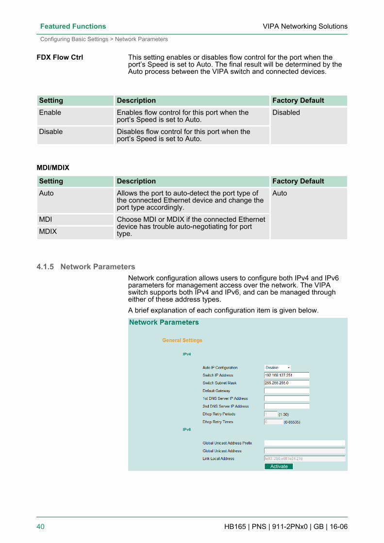
4.1.5 Network ParametersNetwork configuration allows users to configure both IPv4 and IPv6parameters for management access over the network. The VIPAswitch supports both IPv4 and IPv6, and can be managed througheither of these address types.A brief explanation of each configuration item is given below.
FDX Flow Ctrl
VIPA Networking SolutionsFeatured Functions
Configuring Basic Settings > Network Parameters
HB165 | PNS | 911-2PNx0 | GB | 16-06 40
The IPv4 settings include the switch’s IP address and subnet mask,as well as the IP address of the default gateway. In addition, inputcells are provided for the IP addresses of a 1st and 2nd DNS server.
Auto IP Configuration
Setting Description Factory DefaultDisable The VIPA switch’s IP address must be set man-
ually.Disable
By DHCP The VIPA switch’s IP address will be assignedautomaticallyby the network’s DHCP server.
By BootP The VIPA switch’s IP address will be assignedautomaticallyby the network’s BootP server.
Switch IP Address
Setting Description Factory DefaultIP address for theVIPA switch
Assigns the VIPA switch’s IP address on aTCP/IP network.
192.168.127.253
Switch Subnet Mask
Setting Description Factory DefaultSubnet mask forthe VIPA switch
Identifies the type of network the VIPA switch isconnected to(e.g., 255.255.0.0 for a Class B network,or 255.255.255.0 for a Class C network).
255.255.255.0
Default Gateway
Setting Description Factory DefaultIP address forgateway
Specifies the IP address of the router that con-nects the LAN to an outside network.
None
IP4
VIPA Networking Solutions Featured Functions
Configuring Basic Settings > Network Parameters
HB165 | PNS | 911-2PNx0 | GB | 16-06 41
DNS IP Address
Setting Description Factory DefaultIP address for1st DNS server
Specifies the IP address of the DNS serverused by your network. After specifying the DNSserver’s IP address, you can use the VIPAswitch’s URL to open the web console insteadof entering the IP address.
None
IP address for2nd DNS server
Specifies the IP address of the secondary DNSserver used by your network. The VIPA switchwill use the secondary DNS server if the firstDNS server fails to connect.
None
DHCP Retry Periods
Setting Description Factory Default1 to 30 Users can configure the DHCP retry period
manually1
DHCP Retry Times
Setting Description Factory Default0 to 65535 Users can configure the times of DHCP retry
manually0
VIPA Networking SolutionsFeatured Functions
Configuring Basic Settings > Network Parameters
HB165 | PNS | 911-2PNx0 | GB | 16-06 42
The IPv6 settings include two distinct address types—Link-Local Uni-cast addresses and Global Unicast addresses. A Link-Local addressmakes the switch accessible over IPv6 for all devices attached to thesame local subnet. To connect to a larger network with multiple seg-ments, the switch must be configured with a Global Unicast address.
Global Unicast Address Prefix (Prefix Length: 64 bits) Default Gateway
Setting Description Factory DefaultGlobal UnicastAddress Prefix
The prefix value must be formatted according tothe RFC 2373 “IPv6 Addressing Architecture”using 8 colon-separated 16-bit hexadecimalvalues. One double colon may be used in theaddress to indicate the appropriate number ofzeros required to fill the undefined fields.
None
Global Unicast Address
Setting Description Factory DefaultNone Displays the IPv6 Global Unicast address. The
network portion of the Global Unicast addresscan be configured by specifying the Global Uni-cast Prefix and using an EUI-64 interface ID inthe low order 64 bits. The host portion of theGlobal Unicast address is automatically gener-ated using the modified EUI-64 form of theinterface identifier (Switch’s MAC address).
None
Link-Local Address
Setting Description Factory DefaultNone The network portion of the Link-Local address
is FE80 and the host portion of the Link-Localaddress is automatically generated using themodified EUI-64 form of the interface identifier(Switch’s MAC address)
None
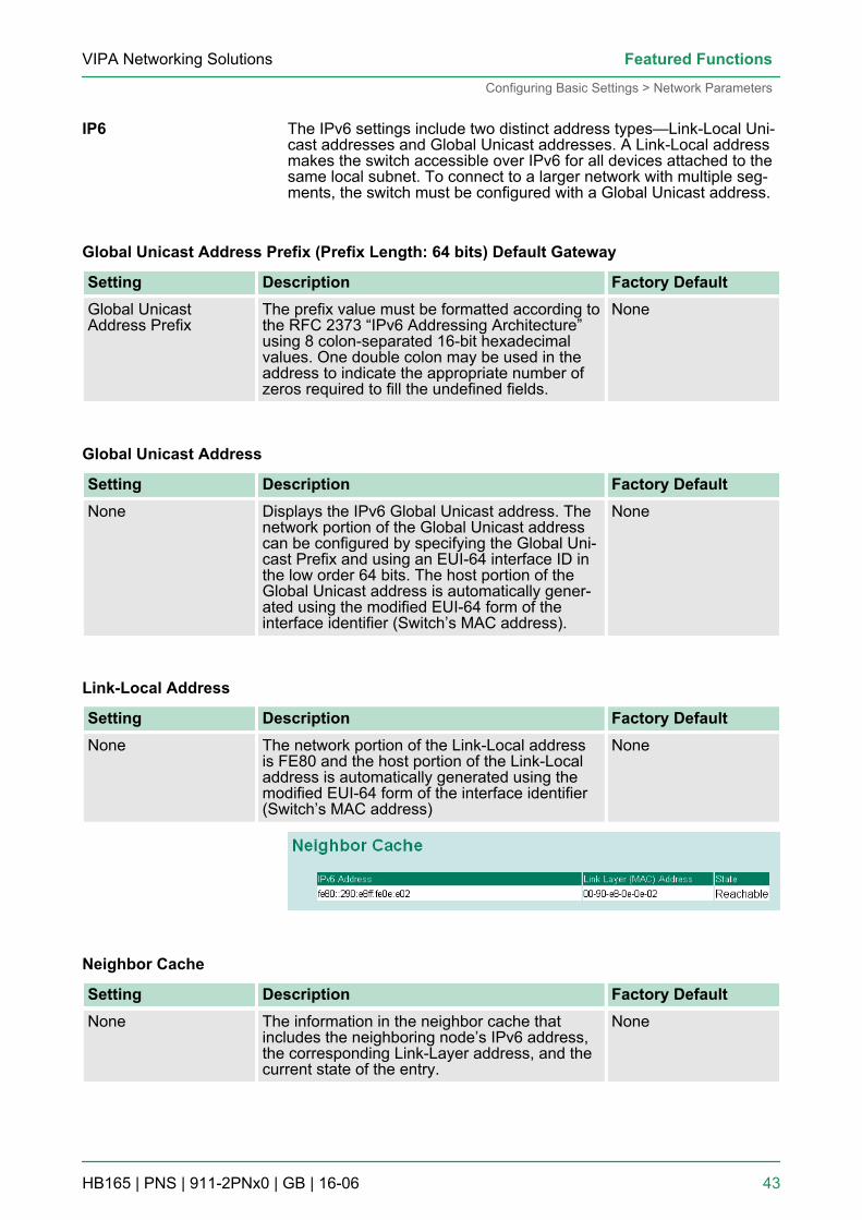
Neighbor Cache
Setting Description Factory DefaultNone The information in the neighbor cache that
includes the neighboring node’s IPv6 address,the corresponding Link-Layer address, and thecurrent state of the entry.
None
IP6
VIPA Networking Solutions Featured Functions
Configuring Basic Settings > Network Parameters
HB165 | PNS | 911-2PNx0 | GB | 16-06 43
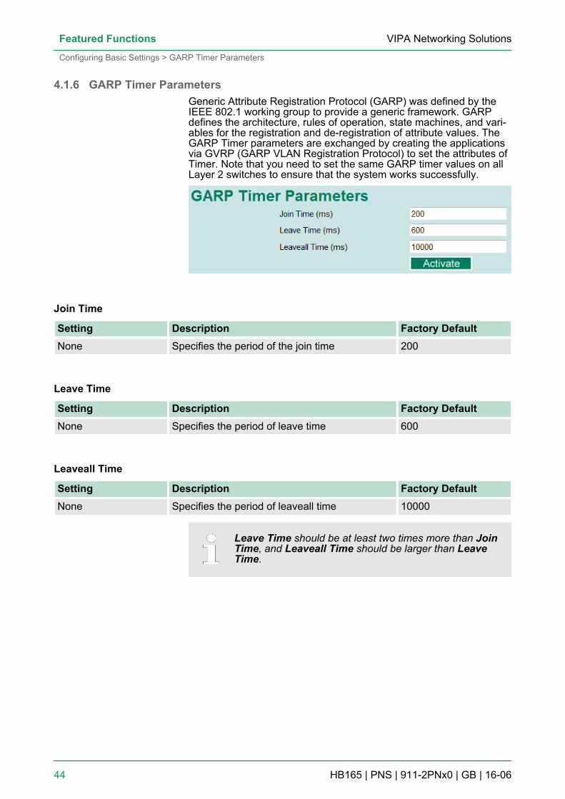
4.1.6 GARP Timer ParametersGeneric Attribute Registration Protocol (GARP) was defined by theIEEE 802.1 working group to provide a generic framework. GARPdefines the architecture, rules of operation, state machines, and vari-ables for the registration and de-registration of attribute values. TheGARP Timer parameters are exchanged by creating the applicationsvia GVRP (GARP VLAN Registration Protocol) to set the attributes ofTimer. Note that you need to set the same GARP timer values on allLayer 2 switches to ensure that the system works successfully.
Join Time
Setting Description Factory DefaultNone Specifies the period of the join time 200
Leave Time
Setting Description Factory DefaultNone Specifies the period of leave time 600
Leaveall Time
Setting Description Factory DefaultNone Specifies the period of leaveall time 10000
Leave Time should be at least two times more than JoinTime, and Leaveall Time should be larger than LeaveTime.
VIPA Networking SolutionsFeatured Functions
Configuring Basic Settings > GARP Timer Parameters
HB165 | PNS | 911-2PNx0 | GB | 16-06 44
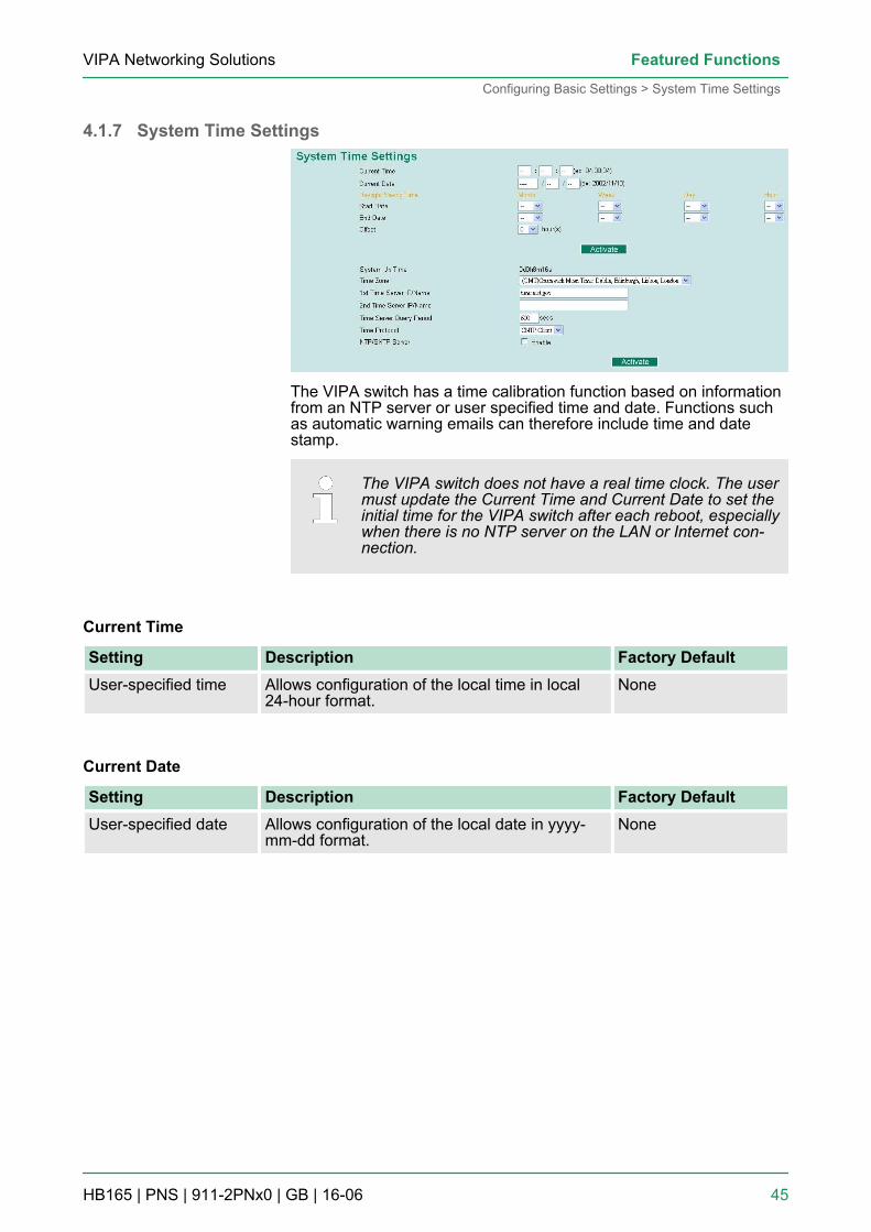
4.1.7 System Time Settings
The VIPA switch has a time calibration function based on informationfrom an NTP server or user specified time and date. Functions suchas automatic warning emails can therefore include time and datestamp.
The VIPA switch does not have a real time clock. The usermust update the Current Time and Current Date to set theinitial time for the VIPA switch after each reboot, especiallywhen there is no NTP server on the LAN or Internet con-nection.
Current Time
Setting Description Factory DefaultUser-specified time Allows configuration of the local time in local
24-hour format.None
Current Date
Setting Description Factory DefaultUser-specified date Allows configuration of the local date in yyyy-
mm-dd format.None
VIPA Networking Solutions Featured Functions
Configuring Basic Settings > System Time Settings
HB165 | PNS | 911-2PNx0 | GB | 16-06 45
The Daylight Saving Time settings are used to automatically set theVIPA switch’s time forward according to national standards.
Start Date
Setting Description Factory DefaultUser-specified date Specifies the date that Daylight Saving Time
begins.None
End Date
Setting Description Factory DefaultUser-specified date Specifies the date that Daylight Saving Time
ends.None
Offset
Setting Description Factory DefaultUser-specified hour Specifies the number of hours that the time
should be set forward during Daylight SavingTime.
None
Indicates how long the VIPA switch remained up since the last coldstart. The up time is indicated in seconds.
Time Zone
Setting Description Factory DefaultTime zone Specifies the time zone, which is used to deter-
mine the local time offset from GMT (Green-wich Mean Time).
GMT(Greenwich MeanTime)
Daylight Saving Time
System Up Time
VIPA Networking SolutionsFeatured Functions
Configuring Basic Settings > System Time Settings
HB165 | PNS | 911-2PNx0 | GB | 16-06 46
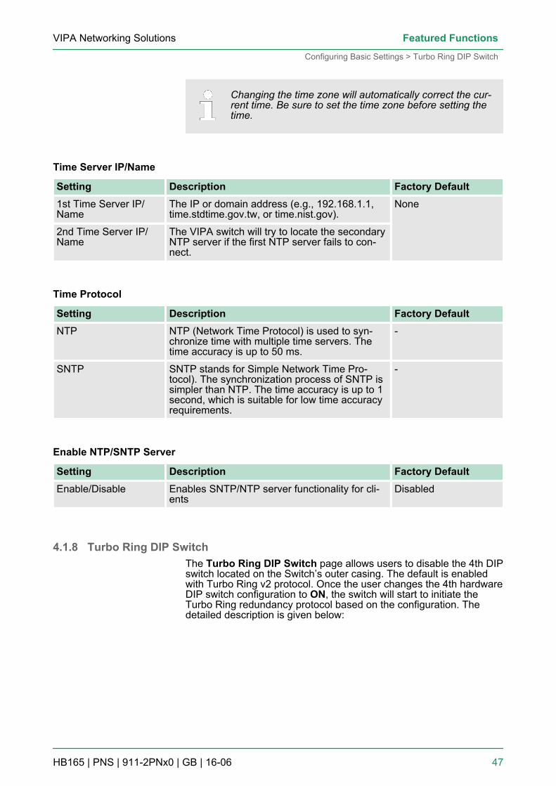
Changing the time zone will automatically correct the cur-rent time. Be sure to set the time zone before setting thetime.
Time Server IP/Name
Setting Description Factory Default1st Time Server IP/Name
The IP or domain address (e.g., 192.168.1.1,time.stdtime.gov.tw, or time.nist.gov).
None
2nd Time Server IP/Name
The VIPA switch will try to locate the secondaryNTP server if the first NTP server fails to con-nect.
Time Protocol
Setting Description Factory DefaultNTP NTP (Network Time Protocol) is used to syn-
chronize time with multiple time servers. Thetime accuracy is up to 50 ms.
-
SNTP SNTP stands for Simple Network Time Pro-tocol). The synchronization process of SNTP issimpler than NTP. The time accuracy is up to 1second, which is suitable for low time accuracyrequirements.
-
Enable NTP/SNTP Server
Setting Description Factory DefaultEnable/Disable Enables SNTP/NTP server functionality for cli-
entsDisabled
4.1.8 Turbo Ring DIP SwitchThe Turbo Ring DIP Switch page allows users to disable the 4th DIPswitch located on the Switch’s outer casing. The default is enabledwith Turbo Ring v2 protocol. Once the user changes the 4th hardwareDIP switch configuration to ON, the switch will start to initiate theTurbo Ring redundancy protocol based on the configuration. Thedetailed description is given below:
VIPA Networking Solutions Featured Functions
Configuring Basic Settings > Turbo Ring DIP Switch
HB165 | PNS | 911-2PNx0 | GB | 16-06 47
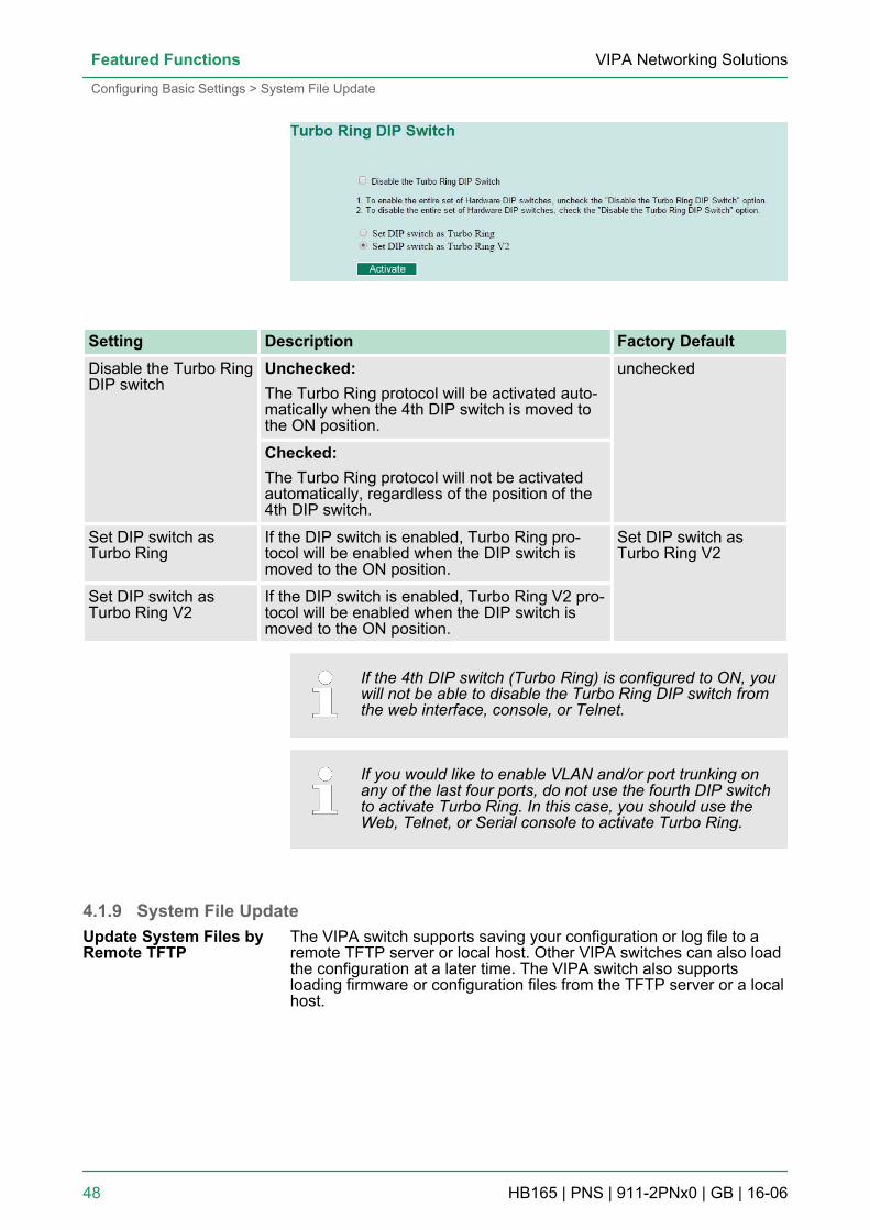
Setting Description Factory DefaultDisable the Turbo RingDIP switch
Unchecked:The Turbo Ring protocol will be activated auto-matically when the 4th DIP switch is moved tothe ON position.
unchecked
Checked:The Turbo Ring protocol will not be activatedautomatically, regardless of the position of the4th DIP switch.
Set DIP switch asTurbo Ring
If the DIP switch is enabled, Turbo Ring pro-tocol will be enabled when the DIP switch ismoved to the ON position.
Set DIP switch asTurbo Ring V2
Set DIP switch asTurbo Ring V2
If the DIP switch is enabled, Turbo Ring V2 pro-tocol will be enabled when the DIP switch ismoved to the ON position.
If the 4th DIP switch (Turbo Ring) is configured to ON, youwill not be able to disable the Turbo Ring DIP switch fromthe web interface, console, or Telnet.
If you would like to enable VLAN and/or port trunking onany of the last four ports, do not use the fourth DIP switchto activate Turbo Ring. In this case, you should use theWeb, Telnet, or Serial console to activate Turbo Ring.
4.1.9 System File UpdateThe VIPA switch supports saving your configuration or log file to aremote TFTP server or local host. Other VIPA switches can also loadthe configuration at a later time. The VIPA switch also supportsloading firmware or configuration files from the TFTP server or a localhost.
Update System Files byRemote TFTP
VIPA Networking SolutionsFeatured Functions
Configuring Basic Settings > System File Update
HB165 | PNS | 911-2PNx0 | GB | 16-06 48
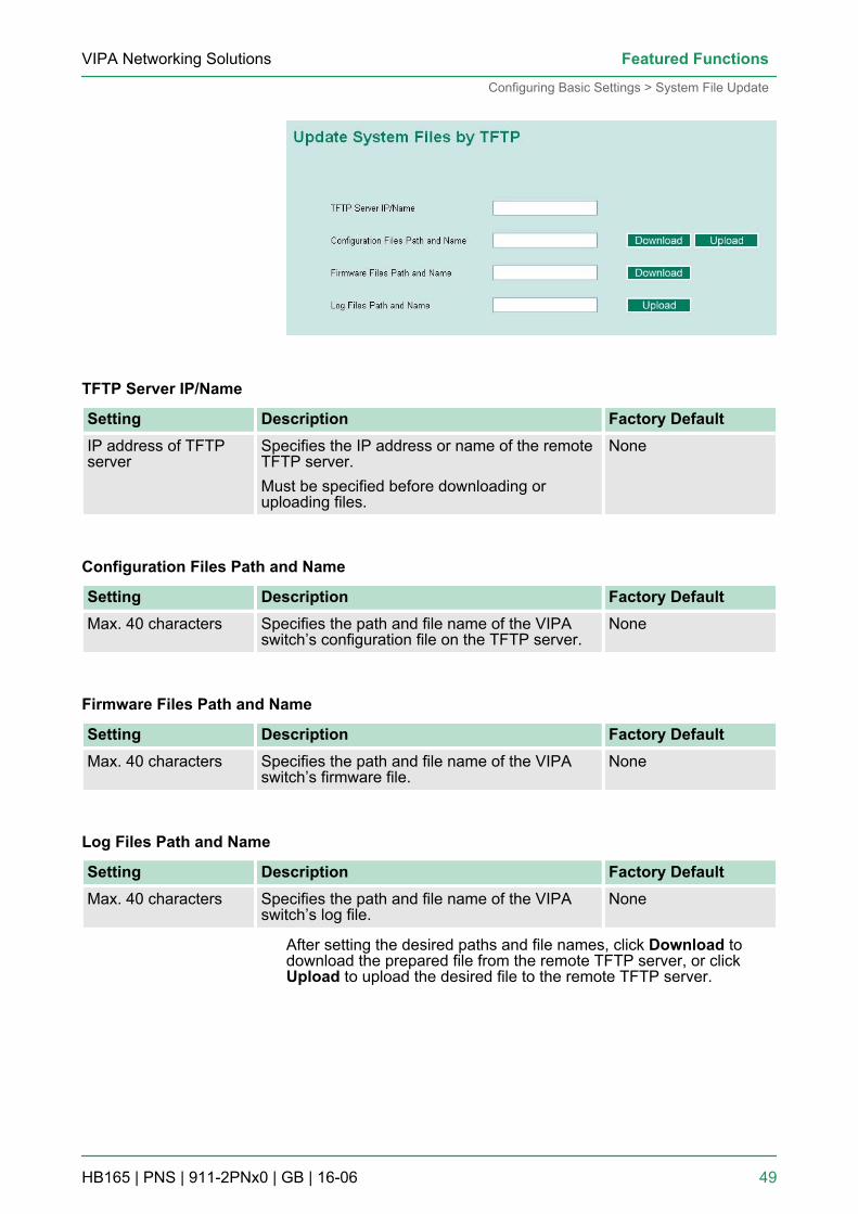
TFTP Server IP/Name
Setting Description Factory DefaultIP address of TFTPserver
Specifies the IP address or name of the remoteTFTP server.Must be specified before downloading oruploading files.
None
Configuration Files Path and Name
Setting Description Factory DefaultMax. 40 characters Specifies the path and file name of the VIPA
switch’s configuration file on the TFTP server.None
Firmware Files Path and Name
Setting Description Factory DefaultMax. 40 characters Specifies the path and file name of the VIPA
switch’s firmware file.None
Log Files Path and Name
Setting Description Factory DefaultMax. 40 characters Specifies the path and file name of the VIPA
switch’s log file.None
After setting the desired paths and file names, click Download todownload the prepared file from the remote TFTP server, or clickUpload to upload the desired file to the remote TFTP server.
VIPA Networking Solutions Featured Functions
Configuring Basic Settings > System File Update
HB165 | PNS | 911-2PNx0 | GB | 16-06 49
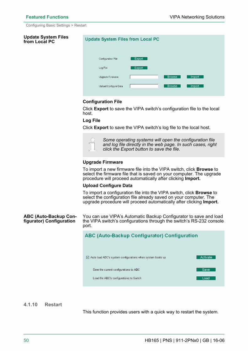
Configuration FileClick Export to save the VIPA switch’s configuration file to the localhost.Log FileClick Export to save the VIPA switch’s log file to the local host.
Some operating systems will open the configuration fileand log file directly in the web page. In such cases, rightclick the Export button to save the file.
Upgrade FirmwareTo import a new firmware file into the VIPA switch, click Browse toselect the firmware file that is saved on your computer. The upgradeprocedure will proceed automatically after clicking Import.Upload Configure DataTo import a configuration file into the VIPA switch, click Browse toselect the configuration file already saved on your computer. Theupgrade procedure will proceed automatically after clicking Import.
You can use VIPA’s Automatic Backup Configurator to save and loadthe VIPA switch’s configurations through the switch’s RS-232 consoleport.
4.1.10 RestartThis function provides users with a quick way to restart the system.
Update System Filesfrom Local PC
ABC (Auto-Backup Con-figurator) Configuration
VIPA Networking SolutionsFeatured Functions
Configuring Basic Settings > Restart
HB165 | PNS | 911-2PNx0 | GB | 16-06 50
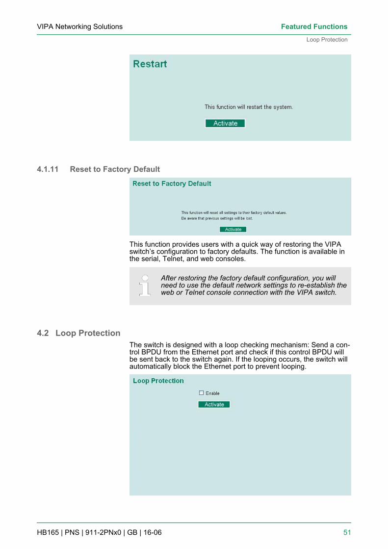
4.1.11 Reset to Factory Default
This function provides users with a quick way of restoring the VIPAswitch’s configuration to factory defaults. The function is available inthe serial, Telnet, and web consoles.
After restoring the factory default configuration, you willneed to use the default network settings to re-establish theweb or Telnet console connection with the VIPA switch.
4.2 Loop ProtectionThe switch is designed with a loop checking mechanism: Send a con-trol BPDU from the Ethernet port and check if this control BPDU willbe sent back to the switch again. If the looping occurs, the switch willautomatically block the Ethernet port to prevent looping.
VIPA Networking Solutions Featured Functions
Loop Protection
HB165 | PNS | 911-2PNx0 | GB | 16-06 51
Check the Enable box and click Activate to enable the Loop protec-tion.
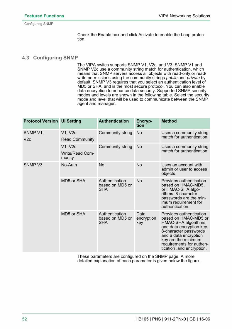
4.3 Configuring SNMPThe VIPA switch supports SNMP V1, V2c, and V3. SNMP V1 andSNMP V2c use a community string match for authentication, whichmeans that SNMP servers access all objects with read-only or read/write permissions using the community strings public and private bydefault. SNMP V3 requires that you select an authentication level ofMD5 or SHA, and is the most secure protocol. You can also enabledata encryption to enhance data security. Supported SNMP securitymodes and levels are shown in the following table. Select the securitymode and level that will be used to communicate between the SNMPagent and manager.
Protocol Version UI Setting Authentication Encryp-tion
Method
SNMP V1,V2c
V1, V2cRead Community
Community string No Uses a community stringmatch for authentication.
V1, V2cWrite/Read Com-munity
Community string No Uses a community stringmatch for authentication.
SNMP V3 No-Auth No No Uses an account withadmin or user to accessobjects
MD5 or SHA Authenticationbased on MD5 orSHA
No Provides authenticationbased on HMAC-MD5,or HMAC-SHA algo-rithms. 8-characterpasswords are the min-imum requirement forauthentication.
MD5 or SHA Authenticationbased on MD5 orSHA
Dataencryptionkey
Provides authenticationbased on HMAC-MD5 orHMAC-SHA algorithms,and data encryption key.8-character passwordsand a data encryptionkey are the minimumrequirements for authen-tication .and encryption.
These parameters are configured on the SNMP page. A moredetailed explanation of each parameter is given below the figure.
VIPA Networking SolutionsFeatured Functions
Configuring SNMP
HB165 | PNS | 911-2PNx0 | GB | 16-06 52
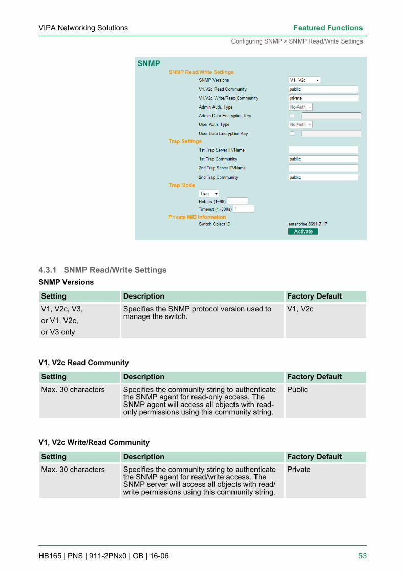
4.3.1 SNMP Read/Write SettingsSNMP Versions
Setting Description Factory DefaultV1, V2c, V3,or V1, V2c,or V3 only
Specifies the SNMP protocol version used tomanage the switch.
V1, V2c
V1, V2c Read Community
Setting Description Factory DefaultMax. 30 characters Specifies the community string to authenticate
the SNMP agent for read-only access. TheSNMP agent will access all objects with read-only permissions using this community string.
Public
V1, V2c Write/Read Community
Setting Description Factory DefaultMax. 30 characters Specifies the community string to authenticate
the SNMP agent for read/write access. TheSNMP server will access all objects with read/write permissions using this community string.
Private
VIPA Networking Solutions Featured Functions
Configuring SNMP > SNMP Read/Write Settings
HB165 | PNS | 911-2PNx0 | GB | 16-06 53
For SNMP V3, two levels of privilege are available accessing theVIPA switch. Admin privilege provides access and authorization toread and write the MIB file. User privilege allows reading of the MIBfile only.
Admin Auth. Type (for SNMP V1, V2c, V3, and V3 only)
Setting Description Factory DefaultNoAuth Allows the admin account to access objects
without authentication.No
MD5- Auth Authentication will be based on the HMAC-MD5algorithms.8-character passwords are the minimumrequirement for authentication.
No
SHA-Auth Authentication will be based on the HMAC-SHAalgorithms.8-character passwords are the minimumrequirement for authentication.
No
Admin Data Encryption Key (for SNMP V1, V2c, V3, and V3 only)
Setting Description Factory DefaultEnable Enables data encryption using the specified
data encryption key(between 8 and 30 characters).
No
Disable Specifies that data will not be encrypted. No
User Auth. Type (for SNMP V1, V2c, V3 and V3 only)
Setting Description Factory DefaultNo-Auth Allows the admin account and user account to
access objects without authentication.No
MD5-Auth Authentication will be based on the HMAC-MD5algorithms.8-character passwords are the minimumrequirement for authentication.
No
SHA-Auth Authentication will be based on the HMAC-SHAalgorithms.8-character passwords are the minimumrequirement for authentication.
No
VIPA Networking SolutionsFeatured Functions
Configuring SNMP > SNMP Read/Write Settings
HB165 | PNS | 911-2PNx0 | GB | 16-06 54
User Data Encryption Key (for SNMP V1, V2c, V3 and V3 only)
Setting Description Factory DefaultEnable Enables data encryption using the specified
data encryption key(between 8 and 30 characters).
No
Disable No data encryption No
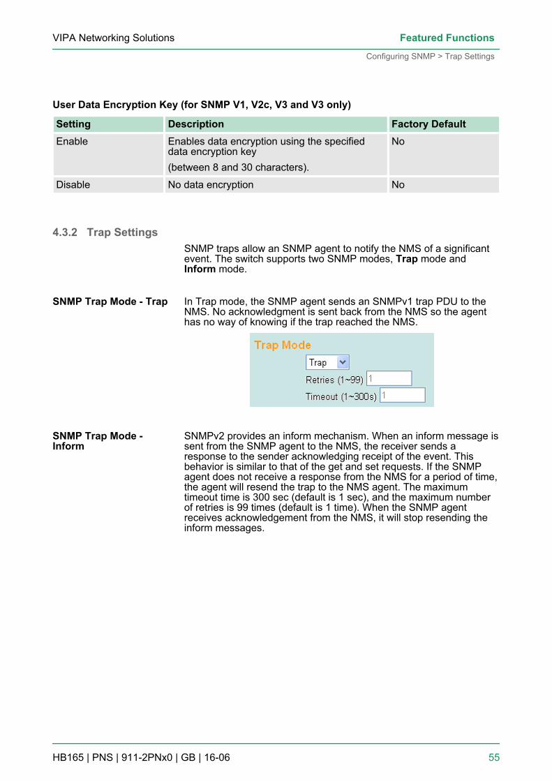
4.3.2 Trap SettingsSNMP traps allow an SNMP agent to notify the NMS of a significantevent. The switch supports two SNMP modes, Trap mode andInform mode.
In Trap mode, the SNMP agent sends an SNMPv1 trap PDU to theNMS. No acknowledgment is sent back from the NMS so the agenthas no way of knowing if the trap reached the NMS.
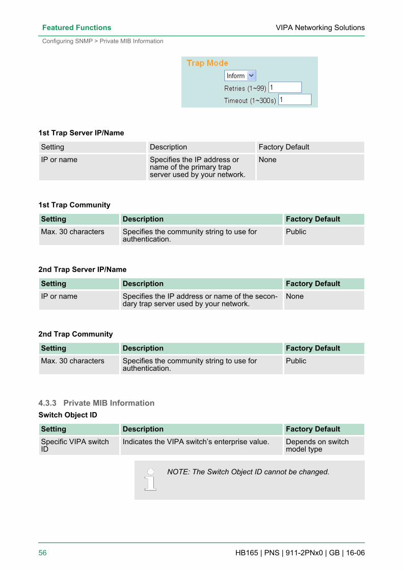
SNMPv2 provides an inform mechanism. When an inform message issent from the SNMP agent to the NMS, the receiver sends aresponse to the sender acknowledging receipt of the event. Thisbehavior is similar to that of the get and set requests. If the SNMPagent does not receive a response from the NMS for a period of time,the agent will resend the trap to the NMS agent. The maximumtimeout time is 300 sec (default is 1 sec), and the maximum numberof retries is 99 times (default is 1 time). When the SNMP agentreceives acknowledgement from the NMS, it will stop resending theinform messages.
SNMP Trap Mode - Trap
SNMP Trap Mode -Inform
VIPA Networking Solutions Featured Functions
Configuring SNMP > Trap Settings
HB165 | PNS | 911-2PNx0 | GB | 16-06 55
1st Trap Server IP/Name
Setting Description Factory Default
IP or name Specifies the IP address orname of the primary trapserver used by your network.
None
1st Trap Community
Setting Description Factory DefaultMax. 30 characters Specifies the community string to use for
authentication.Public
2nd Trap Server IP/Name
Setting Description Factory DefaultIP or name Specifies the IP address or name of the secon-
dary trap server used by your network.None
2nd Trap Community
Setting Description Factory DefaultMax. 30 characters Specifies the community string to use for
authentication.Public
4.3.3 Private MIB InformationSwitch Object ID
Setting Description Factory DefaultSpecific VIPA switchID
Indicates the VIPA switch’s enterprise value. Depends on switchmodel type
NOTE: The Switch Object ID cannot be changed.
VIPA Networking SolutionsFeatured Functions
Configuring SNMP > Private MIB Information
HB165 | PNS | 911-2PNx0 | GB | 16-06 56
4.4 Using Traffic PrioritizationThe VIPA switch’s traffic prioritization capability provides Quality ofService (QoS) to your network by making data delivery more reliable.You can prioritize traffic on your network to ensure that high prioritydata is transmitted with minimum delay. Traffic can be controlled by aset of rules to obtain the required Quality of Service for your network.The rules define different types of traffic and specify how each typeshould be treated as it passes through the switch. The VIPA switchcan inspect both IEEE 802.1p/1Q layer 2 CoS tags, and even layer 3TOS information to provide consistent classification of the entire net-work. The VIPA switch’s QoS capability improves the performanceand determinism of industrial networks for mission critical applica-tions.
4.4.1 The Traffic Prioritization ConceptTraffic prioritization allows you to prioritize data so that time-sensitiveand system-critical data can be transferred smoothly and with minimaldelay over a network. The benefits of using traffic prioritization are:n Improve network performance by controlling a wide variety of
traffic and managing congestion.n Assign priorities to different categories of traffic. For example, set
higher priorities for time-critical or business-critical applications.n Provide predictable throughput for multimedia applications, such
as video conferencing or voice over IP, and minimize traffic delayand jitter.
n Improve network performance as the amount of traffic grows.Doing so will reduce costs since it will not be necessary to keepadding bandwidth to the network.
Traffic prioritization uses the four traffic queues that are present inyour VIPA switch to ensure that high priority traffic is forwarded on adifferent queue from lower priority traffic. Traffic prioritization providesQuality of Service (QoS) to your network.VIPA switch traffic prioritization depends on two industry-standardmethods:n IEEE 802.1D—a layer 2 marking scheme.n Differentiated Services (DiffServ)—a layer 3 marking scheme.
VIPA Networking Solutions Featured Functions
Using Traffic Prioritization > The Traffic Prioritization Concept
HB165 | PNS | 911-2PNx0 | GB | 16-06 57
n The IEEE Std 802.1D, 1998 Edition marking scheme, which is anenhancement to IEEE Std 802.1D, enables Quality of Service onthe LAN. Traffic service levels are defined in the IEEE 802.1Q 4-byte tag, which is used to carry VLAN identification as well asIEEE 802.1p priority information. The 4-byte tag immediately fol-lows the destination MAC address and Source MAC address.
n The IEEE Std 802.1D, 1998 Edition priority marking schemeassigns an IEEE 802.1p priority level between 0 and 7 to eachframe. The priority marking scheme determines the level ofservice that this type of traffic should receive. Refer to the tablebelow for an example of how different traffic types can be mappedto the eight IEEE 802.1p priority levels.
IEEE 802.1p PriorityLevel
IEEE 802.1D Traffic Type
0 Best Effort (default)
1 Background
2 Standard (spare)
3 Excellent Effort (business critical)
4 Controlled Load (streaming multimedia)
5 Video (interactive media); less than 100 milliseconds of latency and jitter
6 Voice (interactive voice); less than 10 milliseconds of latency and jitter
7 Network Control Reserved traffic
Even though the IEEE 802.1D standard is the most widely used pri-oritization scheme in the LAN environment, it still has some restric-tions:n It requires an additional 4-byte tag in the frame, which is normally
optional for Ethernet networks. Without this tag, the schemecannot work.
n The tag is part of the IEEE 802.1Q header, so to implement QoSat layer 2, the entire network must implement IEEE 802.1Q VLANtagging.
n It is only supported on a LAN and not across routed WAN links,since the IEEE 802.1Q tags are removed when the packets passthrough a router.
DiffServ is a Layer 3 marking scheme that uses the DiffServ CodePoint (DSCP) field in the IP header to store the packet priority infor-mation. DSCP is an advanced intelligent method of traffic markingthat allows you to choose how your network prioritizes different typesof traffic. DSCP uses 64 values that map to user-defined servicelevels, allowing you to establish more control over network traffic.The advantages of DiffServ over IEEE 802.1D are:n You can configure how you want your switch to treat selected
applications and types of traffic by assigning various grades ofnetwork service to them.
n No extra tags are required in the packet.
IEEE 802.1D TrafficMarking
Differentiated Services(DiffServ) TrafficMarking
VIPA Networking SolutionsFeatured Functions
Using Traffic Prioritization > The Traffic Prioritization Concept
HB165 | PNS | 911-2PNx0 | GB | 16-06 58
n DSCP uses the IP header of a packet to preserve priority acrossthe Internet.
n DSCP is backwards compatible with IPV4 TOS, which allowsoperation with existing devices that use a layer 3 TOS enabledprioritization scheme.
VIPA switches classify traffic based on layer 2 of the OSI 7 layermodel, and the switch prioritizes received traffic according to the pri-ority information defined in the received packet. Incoming traffic isclassified based upon the IEEE 802.1D frame and is assigned to theappropriate priority queue based on the IEEE 802.1p service levelvalue defined in that packet. Service level markings (values) aredefined in the IEEE 802.1Q 4-byte tag, and consequently traffic willonly contain 802.1p priority markings if the network is configured withVLANs and VLAN tagging. The traffic flow through the switch is asfollows:n A packet received by the VIPA switch may or may not have an
802.1p tag associated with it. If it does not, then it is given adefault 802.1p tag (which is usually 0). Alternatively, the packetmay be marked with a new 802.1p value, which will result in allknowledge of the old 802.1p tag being lost.
n Because the 802.1p priority levels are fixed to the traffic queues,the packet will be placed in the appropriate priority queue, readyfor transmission through the appropriate egress port. When thepacket reaches the head of its queue and is about to be trans-mitted, the device determines whether or not the egress port istagged for that VLAN. If it is, then the new 802.1p tag is used inthe extended 802.1D header.
n The VIPA switch will check a packet received at the ingress portfor IEEE 802.1D traffic classification, and then prioritize it basedon the IEEE 802.1p value (service levels) in that tag. It is this802.1p value that determines which traffic queue the packet ismapped to.
The hardware of VIPA switches has multiple traffic queues that allowpacket prioritization to occur. Higher priority traffic can pass throughthe VIPA switch without being delayed by lower priority traffic. Aseach packet arrives in the VIPA switch, it passes through any ingressprocessing (which includes classification, marking/re-marking), and isthen sorted into the appropriate queue. The switch then forwardspackets from each queue. VIPA switches support two differentqueuing mechanisms:n Weight Fair: This method services all the traffic queues, giving
priority to the higher priority queues. Under most circumstances,the Weight Fair method gives high priority precedence over lowpriority, but in the event that high priority traffic does not reach thelink capacity, lower priority traffic is not blocked.
n Strict: This method services high traffic queues first; low priorityqueues are delayed until no more high priority data needs to besent. The Strict method always gives precedence to high priorityover low priority.
Traffic Prioritization
Traffic Queues
VIPA Networking Solutions Featured Functions
Using Traffic Prioritization > The Traffic Prioritization Concept
HB165 | PNS | 911-2PNx0 | GB | 16-06 59
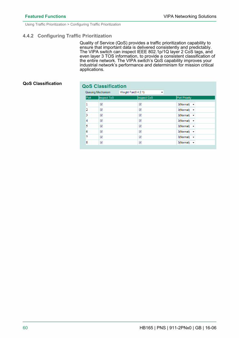
4.4.2 Configuring Traffic PrioritizationQuality of Service (QoS) provides a traffic prioritization capability toensure that important data is delivered consistently and predictably.The VIPA switch can inspect IEEE 802.1p/1Q layer 2 CoS tags, andeven layer 3 TOS information, to provide a consistent classification ofthe entire network. The VIPA switch’s QoS capability improves yourindustrial network’s performance and determinism for mission criticalapplications.
QoS Classification
VIPA Networking SolutionsFeatured Functions
Using Traffic Prioritization > Configuring Traffic Prioritization
HB165 | PNS | 911-2PNx0 | GB | 16-06 60
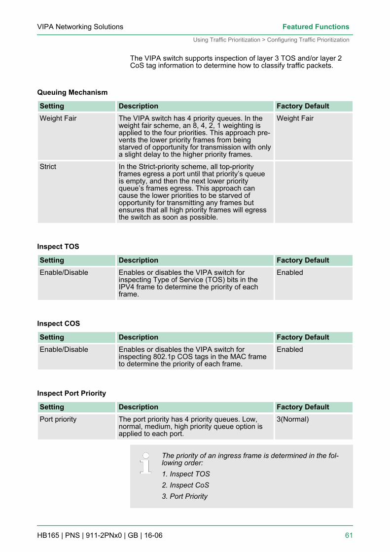
The VIPA switch supports inspection of layer 3 TOS and/or layer 2CoS tag information to determine how to classify traffic packets.
Queuing Mechanism
Setting Description Factory DefaultWeight Fair The VIPA switch has 4 priority queues. In the
weight fair scheme, an 8, 4, 2, 1 weighting isapplied to the four priorities. This approach pre-vents the lower priority frames from beingstarved of opportunity for transmission with onlya slight delay to the higher priority frames.
Weight Fair
Strict In the Strict-priority scheme, all top-priorityframes egress a port until that priority’s queueis empty, and then the next lower priorityqueue’s frames egress. This approach cancause the lower priorities to be starved ofopportunity for transmitting any frames butensures that all high priority frames will egressthe switch as soon as possible.
Inspect TOS
Setting Description Factory DefaultEnable/Disable Enables or disables the VIPA switch for
inspecting Type of Service (TOS) bits in theIPV4 frame to determine the priority of eachframe.
Enabled
Inspect COS
Setting Description Factory DefaultEnable/Disable Enables or disables the VIPA switch for
inspecting 802.1p COS tags in the MAC frameto determine the priority of each frame.
Enabled
Inspect Port Priority
Setting Description Factory DefaultPort priority The port priority has 4 priority queues. Low,
normal, medium, high priority queue option isapplied to each port.
3(Normal)
The priority of an ingress frame is determined in the fol-lowing order:1. Inspect TOS2. Inspect CoS3. Port Priority
VIPA Networking Solutions Featured Functions
Using Traffic Prioritization > Configuring Traffic Prioritization
HB165 | PNS | 911-2PNx0 | GB | 16-06 61
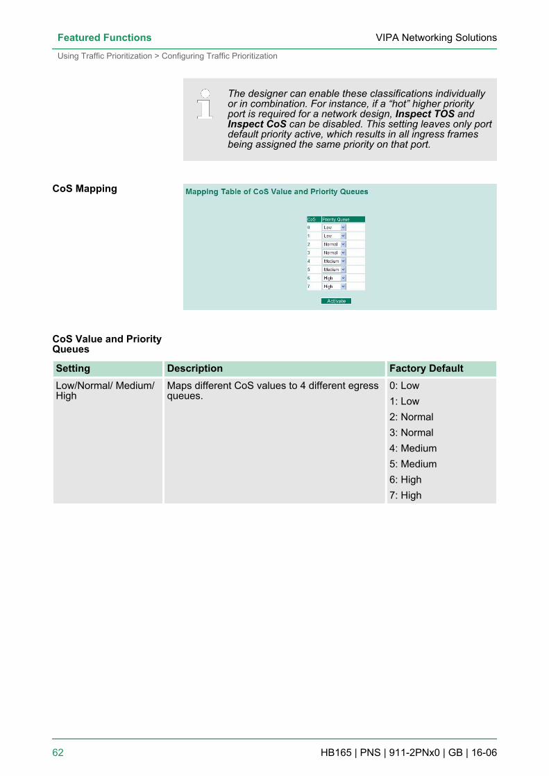
The designer can enable these classifications individuallyor in combination. For instance, if a “hot” higher priorityport is required for a network design, Inspect TOS andInspect CoS can be disabled. This setting leaves only portdefault priority active, which results in all ingress framesbeing assigned the same priority on that port.
Setting Description Factory DefaultLow/Normal/ Medium/High
Maps different CoS values to 4 different egressqueues.
0: Low1: Low2: Normal3: Normal4: Medium5: Medium6: High7: High
CoS Mapping
CoS Value and PriorityQueues
VIPA Networking SolutionsFeatured Functions
Using Traffic Prioritization > Configuring Traffic Prioritization
HB165 | PNS | 911-2PNx0 | GB | 16-06 62
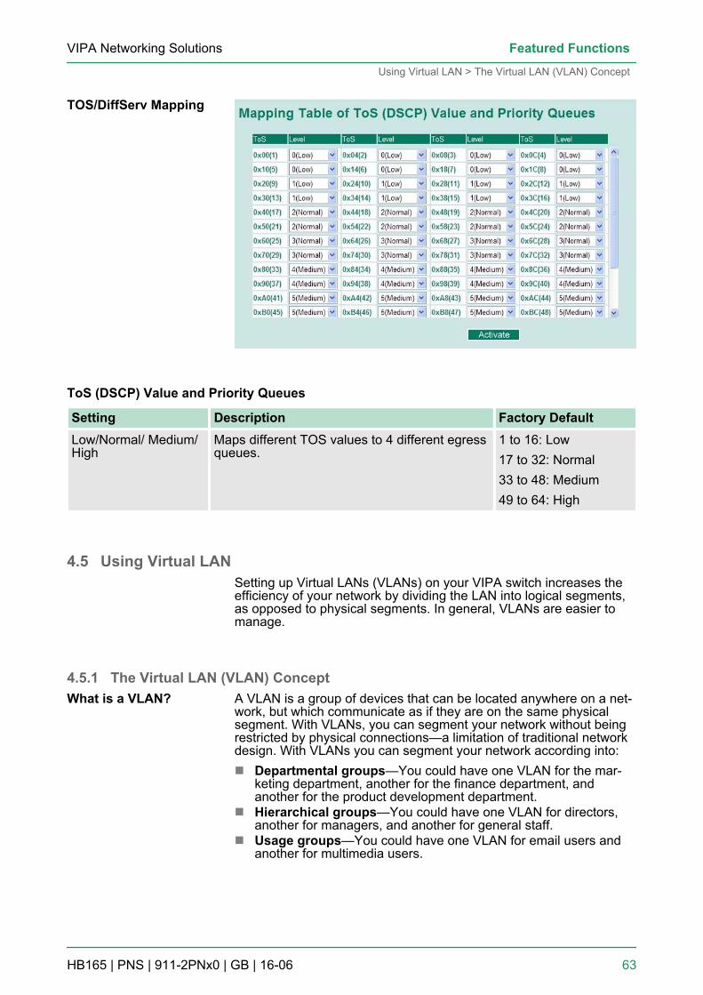
ToS (DSCP) Value and Priority Queues
Setting Description Factory DefaultLow/Normal/ Medium/High
Maps different TOS values to 4 different egressqueues.
1 to 16: Low17 to 32: Normal33 to 48: Medium49 to 64: High
4.5 Using Virtual LANSetting up Virtual LANs (VLANs) on your VIPA switch increases theefficiency of your network by dividing the LAN into logical segments,as opposed to physical segments. In general, VLANs are easier tomanage.
4.5.1 The Virtual LAN (VLAN) ConceptA VLAN is a group of devices that can be located anywhere on a net-work, but which communicate as if they are on the same physicalsegment. With VLANs, you can segment your network without beingrestricted by physical connections—a limitation of traditional networkdesign. With VLANs you can segment your network according into:n Departmental groups—You could have one VLAN for the mar-
keting department, another for the finance department, andanother for the product development department.
n Hierarchical groups—You could have one VLAN for directors,another for managers, and another for general staff.
n Usage groups—You could have one VLAN for email users andanother for multimedia users.
TOS/DiffServ Mapping
What is a VLAN?
VIPA Networking Solutions Featured Functions
Using Virtual LAN > The Virtual LAN (VLAN) Concept
HB165 | PNS | 911-2PNx0 | GB | 16-06 63
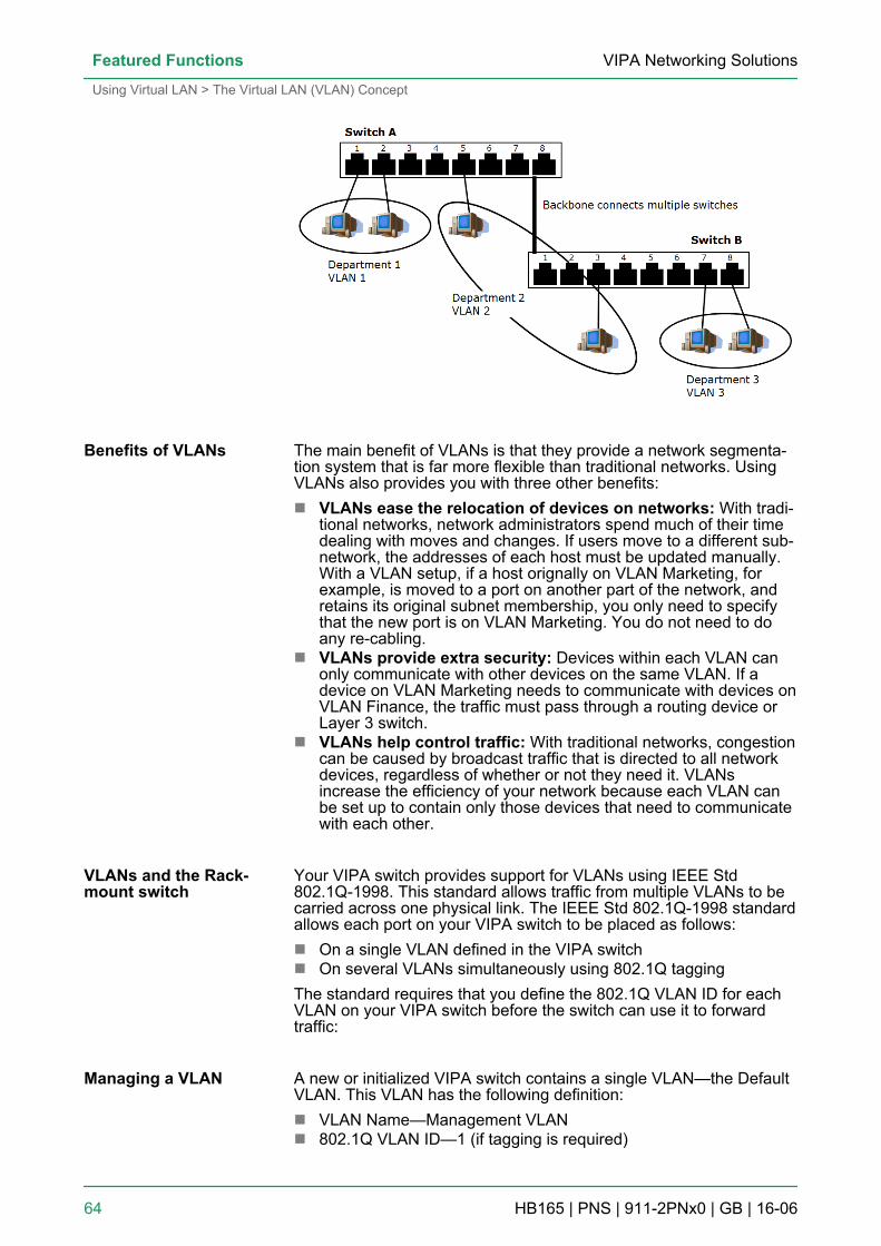
The main benefit of VLANs is that they provide a network segmenta-tion system that is far more flexible than traditional networks. UsingVLANs also provides you with three other benefits:n VLANs ease the relocation of devices on networks: With tradi-
tional networks, network administrators spend much of their timedealing with moves and changes. If users move to a different sub-network, the addresses of each host must be updated manually.With a VLAN setup, if a host orignally on VLAN Marketing, forexample, is moved to a port on another part of the network, andretains its original subnet membership, you only need to specifythat the new port is on VLAN Marketing. You do not need to doany re-cabling.
n VLANs provide extra security: Devices within each VLAN canonly communicate with other devices on the same VLAN. If adevice on VLAN Marketing needs to communicate with devices onVLAN Finance, the traffic must pass through a routing device orLayer 3 switch.
n VLANs help control traffic: With traditional networks, congestioncan be caused by broadcast traffic that is directed to all networkdevices, regardless of whether or not they need it. VLANsincrease the efficiency of your network because each VLAN canbe set up to contain only those devices that need to communicatewith each other.
Your VIPA switch provides support for VLANs using IEEE Std802.1Q-1998. This standard allows traffic from multiple VLANs to becarried across one physical link. The IEEE Std 802.1Q-1998 standardallows each port on your VIPA switch to be placed as follows:n On a single VLAN defined in the VIPA switchn On several VLANs simultaneously using 802.1Q taggingThe standard requires that you define the 802.1Q VLAN ID for eachVLAN on your VIPA switch before the switch can use it to forwardtraffic:
A new or initialized VIPA switch contains a single VLAN—the DefaultVLAN. This VLAN has the following definition:n VLAN Name—Management VLANn 802.1Q VLAN ID—1 (if tagging is required)
Benefits of VLANs
VLANs and the Rack-mount switch
Managing a VLAN
VIPA Networking SolutionsFeatured Functions
Using Virtual LAN > The Virtual LAN (VLAN) Concept
HB165 | PNS | 911-2PNx0 | GB | 16-06 64
All the ports are initially placed on this VLAN, and it is the only VLANthat allows you to access the management software of the VIPAswitch over the network.
If devices connected to a VLAN need to communicate to devices on adifferent VLAN, a router or Layer 3 switching device with connectionsto both VLANs needs to be installed. Communication between VLANscan only take place if they are all connected to a routing or Layer 3switching device.
The VIPA switch supports 802.1Q VLAN tagging, a system thatallows traffic for multiple VLANs to be carried on a single physical link(backbone, trunk). When setting up VLANs you need to understandwhen to use untagged and tagged membership of VLANs. Simply put,if a port is on a single VLAN it can be an untagged member, but if theport needs to be a member of multiple VLANs, tagged membershipmust be defined. A typical host (e.g., clients) will be untagged mem-bers of one VLAN, defined as an Access Port in a VIPA switch, whileinter-switch connections will be tagged members of all VLANs,defined as a Trunk Port in a VIPA switch. The IEEE Std802.1Q-1998 defines how VLANs operate within an open packet-switched network. An 802.1Q compliant packet carries additionalinformation that allows a switch to determine which VLAN the portbelongs to. If a frame is carrying the additional information, it is knownas a tagged frame. To carry multiple VLANs across a single physicallink (backbone, trunk), each packet must be tagged with a VLANidentifier so that the switches can identify which packets belong inwhich VLAN. To communicate between VLANs, a router must beused.The VIPA switch supports three types of VLAN port settings:n Access Port: The port connects to a single device that is not
tagged. The user must define the default port PVID that assignswhich VLAN the device belongs to. Once the ingress packet ofthis Access Port egresses to another Trunk Port (the port needsall packets to carry tag information), the VIPA switch will insert thisPVID into this packet so the next 802.1Q VLAN switch can recog-nize it.
n Trunk Port: The port connects to a LAN that consists of untaggeddevices, tagged devices and/or switches and hubs. In general, thetraffic of the Trunk Port must have a Tag. Users can also assign aPVID to a Trunk Port. The untagged packet on the Trunk Port willbe assigned the port default PVID as its VID.
n Hybrid Port: The port is similar to a Trunk port, except users canexplicitly assign tags to be removed from egress packets.
The following section illustrates how to use these ports to set up dif-ferent applications.
CommunicationBetween VLANs
VLANs: Tagged andUntagged Membership
VIPA Networking Solutions Featured Functions
Using Virtual LAN > The Virtual LAN (VLAN) Concept
HB165 | PNS | 911-2PNx0 | GB | 16-06 65
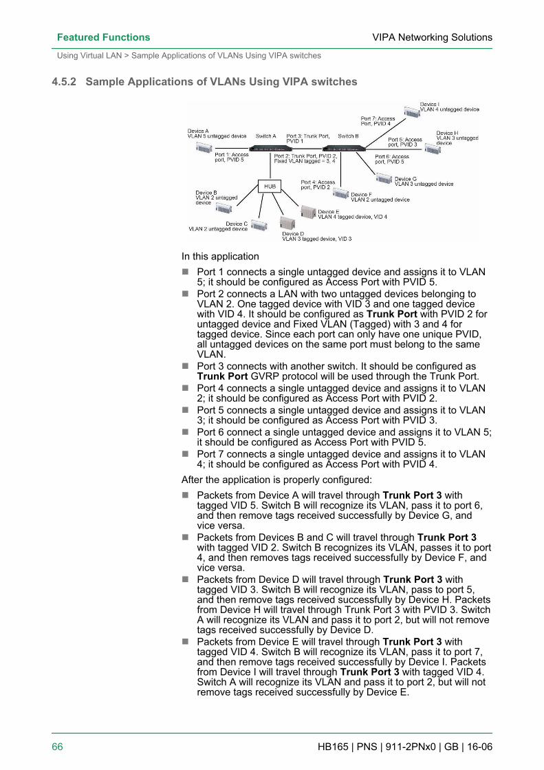
4.5.2 Sample Applications of VLANs Using VIPA switches
In this applicationn Port 1 connects a single untagged device and assigns it to VLAN
5; it should be configured as Access Port with PVID 5.n Port 2 connects a LAN with two untagged devices belonging to
VLAN 2. One tagged device with VID 3 and one tagged devicewith VID 4. It should be configured as Trunk Port with PVID 2 foruntagged device and Fixed VLAN (Tagged) with 3 and 4 fortagged device. Since each port can only have one unique PVID,all untagged devices on the same port must belong to the sameVLAN.
n Port 3 connects with another switch. It should be configured asTrunk Port GVRP protocol will be used through the Trunk Port.
n Port 4 connects a single untagged device and assigns it to VLAN2; it should be configured as Access Port with PVID 2.
n Port 5 connects a single untagged device and assigns it to VLAN3; it should be configured as Access Port with PVID 3.
n Port 6 connect a single untagged device and assigns it to VLAN 5;it should be configured as Access Port with PVID 5.
n Port 7 connects a single untagged device and assigns it to VLAN4; it should be configured as Access Port with PVID 4.
After the application is properly configured:n Packets from Device A will travel through Trunk Port 3 with
tagged VID 5. Switch B will recognize its VLAN, pass it to port 6,and then remove tags received successfully by Device G, andvice versa.
n Packets from Devices B and C will travel through Trunk Port 3with tagged VID 2. Switch B recognizes its VLAN, passes it to port4, and then removes tags received successfully by Device F, andvice versa.
n Packets from Device D will travel through Trunk Port 3 withtagged VID 3. Switch B will recognize its VLAN, pass to port 5,and then remove tags received successfully by Device H. Packetsfrom Device H will travel through Trunk Port 3 with PVID 3. SwitchA will recognize its VLAN and pass it to port 2, but will not removetags received successfully by Device D.
n Packets from Device E will travel through Trunk Port 3 withtagged VID 4. Switch B will recognize its VLAN, pass it to port 7,and then remove tags received successfully by Device I. Packetsfrom Device I will travel through Trunk Port 3 with tagged VID 4.Switch A will recognize its VLAN and pass it to port 2, but will notremove tags received successfully by Device E.
VIPA Networking SolutionsFeatured Functions
Using Virtual LAN > Sample Applications of VLANs Using VIPA switches
HB165 | PNS | 911-2PNx0 | GB | 16-06 66
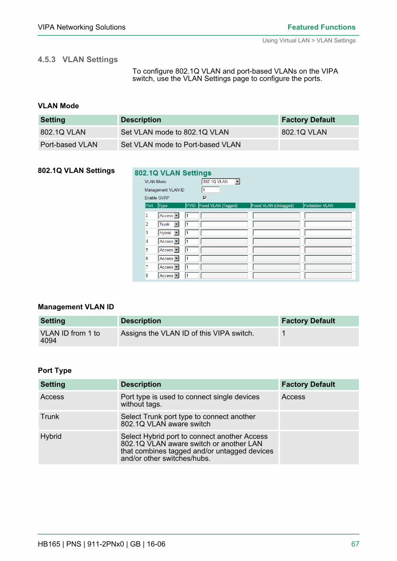
4.5.3 VLAN SettingsTo configure 802.1Q VLAN and port-based VLANs on the VIPAswitch, use the VLAN Settings page to configure the ports.
VLAN Mode
Setting Description Factory Default802.1Q VLAN Set VLAN mode to 802.1Q VLAN 802.1Q VLAN
Port-based VLAN Set VLAN mode to Port-based VLAN
Management VLAN ID
Setting Description Factory DefaultVLAN ID from 1 to4094
Assigns the VLAN ID of this VIPA switch. 1
Port Type
Setting Description Factory DefaultAccess Port type is used to connect single devices
without tags.Access
Trunk Select Trunk port type to connect another802.1Q VLAN aware switch
Hybrid Select Hybrid port to connect another Access802.1Q VLAN aware switch or another LANthat combines tagged and/or untagged devicesand/or other switches/hubs.
802.1Q VLAN Settings
VIPA Networking Solutions Featured Functions
Using Virtual LAN > VLAN Settings
HB165 | PNS | 911-2PNx0 | GB | 16-06 67
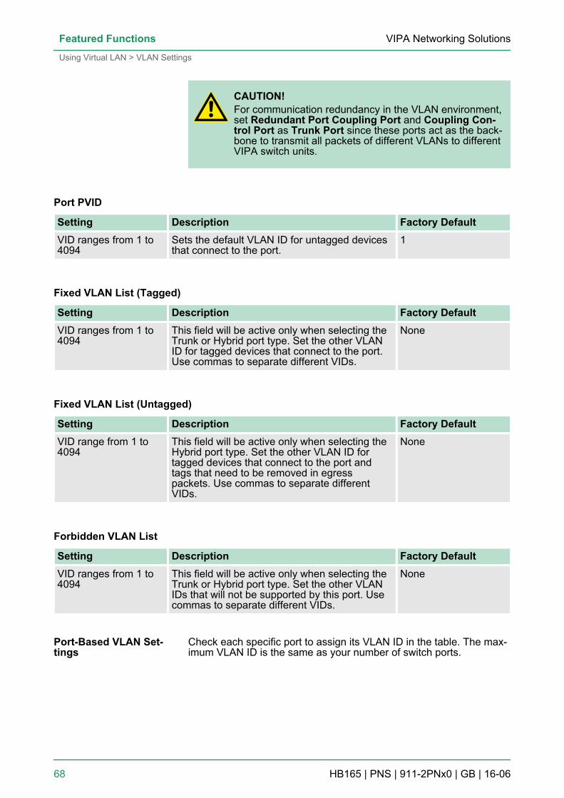
CAUTION!For communication redundancy in the VLAN environment,set Redundant Port Coupling Port and Coupling Con-trol Port as Trunk Port since these ports act as the back-bone to transmit all packets of different VLANs to differentVIPA switch units.
Port PVID
Setting Description Factory DefaultVID ranges from 1 to4094
Sets the default VLAN ID for untagged devicesthat connect to the port.
1
Fixed VLAN List (Tagged)
Setting Description Factory DefaultVID ranges from 1 to4094
This field will be active only when selecting theTrunk or Hybrid port type. Set the other VLANID for tagged devices that connect to the port.Use commas to separate different VIDs.
None
Fixed VLAN List (Untagged)
Setting Description Factory DefaultVID range from 1 to4094
This field will be active only when selecting theHybrid port type. Set the other VLAN ID fortagged devices that connect to the port andtags that need to be removed in egresspackets. Use commas to separate differentVIDs.
None
Forbidden VLAN List
Setting Description Factory DefaultVID ranges from 1 to4094
This field will be active only when selecting theTrunk or Hybrid port type. Set the other VLANIDs that will not be supported by this port. Usecommas to separate different VIDs.
None
Check each specific port to assign its VLAN ID in the table. The max-imum VLAN ID is the same as your number of switch ports.
Port-Based VLAN Set-tings
VIPA Networking SolutionsFeatured Functions
Using Virtual LAN > VLAN Settings
HB165 | PNS | 911-2PNx0 | GB | 16-06 68
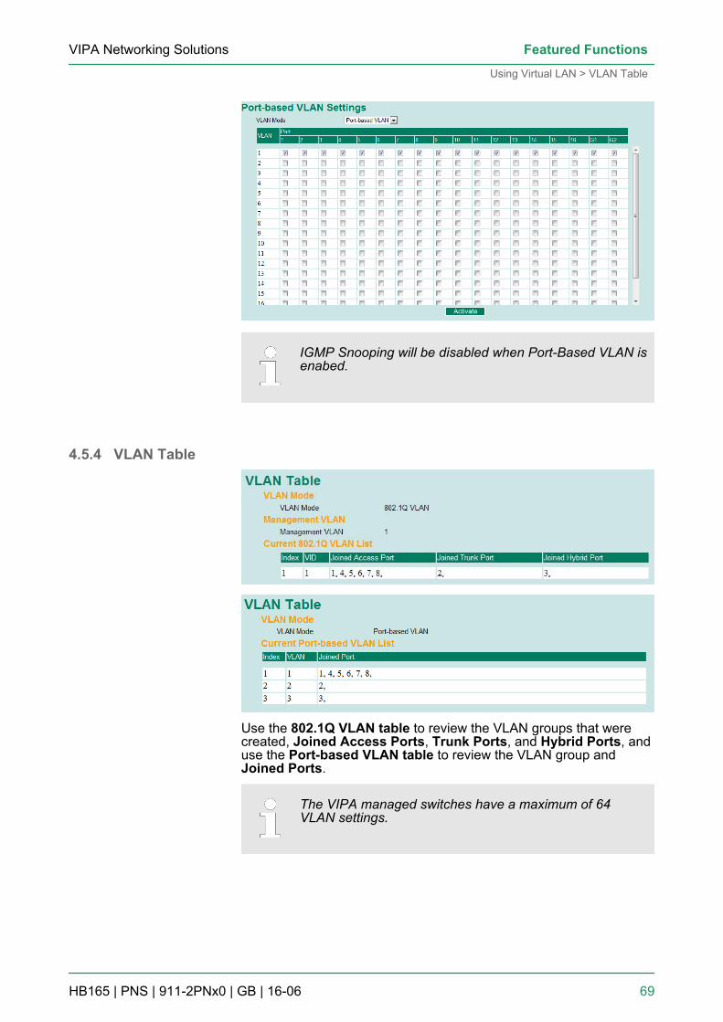
IGMP Snooping will be disabled when Port-Based VLAN isenabed.
4.5.4 VLAN Table
Use the 802.1Q VLAN table to review the VLAN groups that werecreated, Joined Access Ports, Trunk Ports, and Hybrid Ports, anduse the Port-based VLAN table to review the VLAN group andJoined Ports.
The VIPA managed switches have a maximum of 64VLAN settings.
VIPA Networking Solutions Featured Functions
Using Virtual LAN > VLAN Table
HB165 | PNS | 911-2PNx0 | GB | 16-06 69
4.6 Using Multicast FilteringMulticast filtering improves the performance of networks that carrymulticast traffic. This section explains multicasts, multicast filtering,and how multicast filtering can be implemented on your VIPA switch.
4.6.1 The Concept of Multicast FilteringA multicast is a packet sent by one host to multiple hosts. Only thosehosts that belong to a specific multicast group will receive the multi-cast. If the network is set up correctly, a multicast can only be sent toan end-station or a subset of end-stations on a LAN or VLAN thatbelong to the multicast group. Multicast group members can be dis-tributed across multiple subnets, so that multicast transmissions canoccur within a campus LAN or over a WAN. In addition, networks thatsupport IP multicast send only one copy of the desired informationacross the network until the delivery path that reaches group mem-bers diverges. To make more efficient use of network bandwidth, it isonly at these points that multicast packets are duplicated and for-warded. A multicast packet has a multicast group address in the des-tination address field of the packet’s IP header.
The benefits of using IP multicast are:n It uses the most efficient, sensible method to deliver the same
information to many receivers with only one transmission.n It reduces the load on the source (for example, a server) since it
will not need to produce several copies of the same data.n It makes efficient use of network bandwidth and scales well as the
number of multicast group members increases.n Works with other IP protocols and services, such as Quality of
Service (QoS).Multicast transmission makes more sense and is more efficient thanunicast transmission for some applications. For example, multicastsare often used for video-conferencing, since high volumes of trafficmust be sent to several end-stations at the same time, but wherebroadcasting the traffic to all end-stations would cause a substantialreduction in network performance. Furthermore, several industrialautomation protocols, such as Allen-Bradley, EtherNet/IP, SiemensProfibus, and Foundation Fieldbus HSE (High Speed Ethernet), usemulticast. These industrial Ethernet protocols use publisher/sub-scriber communications models by multicasting packets that couldflood a network with heavy traffic. IGMP Snooping is used to prunemulticast traffic so that it travels only to those end destinations thatrequire the traffic, reducing the amount of traffic on the Ethernet LAN.
What is an IP Multicast?
Benefits of Multicast
VIPA Networking SolutionsFeatured Functions
Using Multicast Filtering > The Concept of Multicast Filtering
HB165 | PNS | 911-2PNx0 | GB | 16-06 70
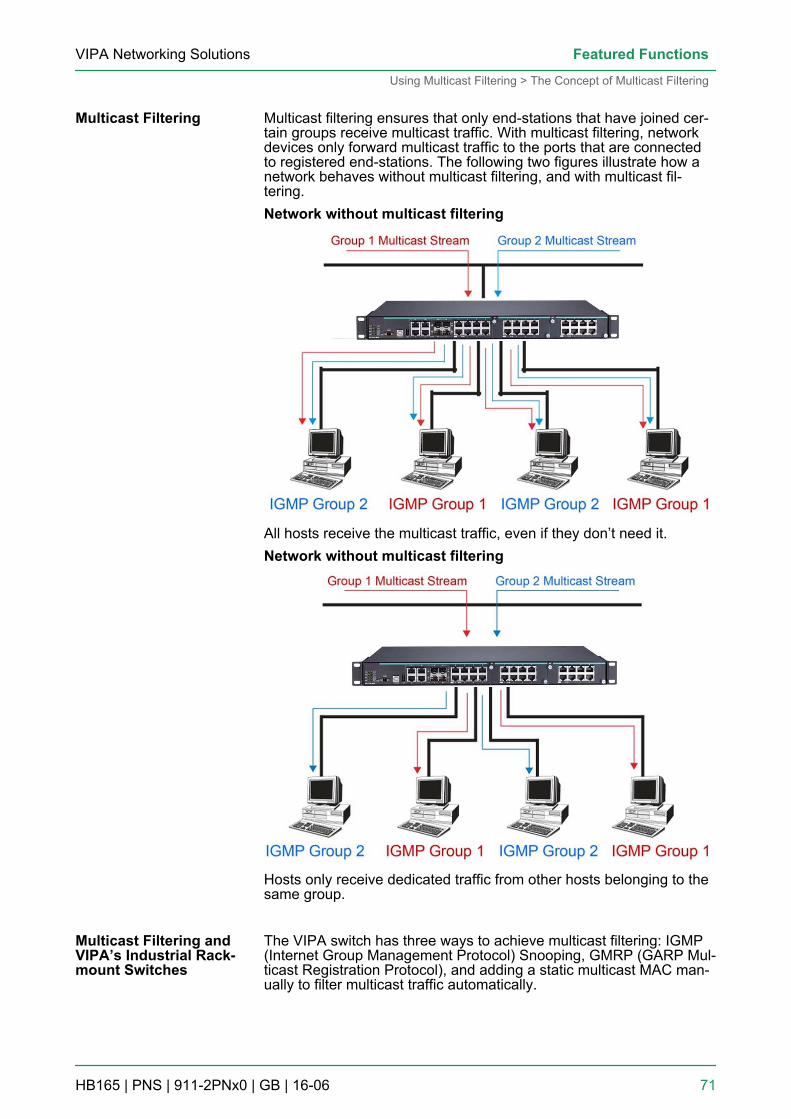
Multicast filtering ensures that only end-stations that have joined cer-tain groups receive multicast traffic. With multicast filtering, networkdevices only forward multicast traffic to the ports that are connectedto registered end-stations. The following two figures illustrate how anetwork behaves without multicast filtering, and with multicast fil-tering.Network without multicast filtering
All hosts receive the multicast traffic, even if they don’t need it.Network without multicast filtering
Hosts only receive dedicated traffic from other hosts belonging to thesame group.
The VIPA switch has three ways to achieve multicast filtering: IGMP(Internet Group Management Protocol) Snooping, GMRP (GARP Mul-ticast Registration Protocol), and adding a static multicast MAC man-ually to filter multicast traffic automatically.
Multicast Filtering
Multicast Filtering andVIPA’s Industrial Rack-mount Switches
VIPA Networking Solutions Featured Functions
Using Multicast Filtering > The Concept of Multicast Filtering
HB165 | PNS | 911-2PNx0 | GB | 16-06 71
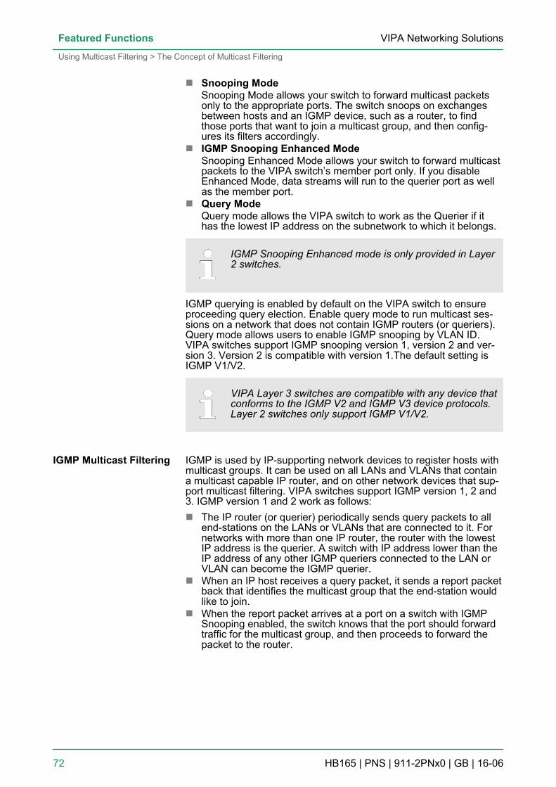
n Snooping ModeSnooping Mode allows your switch to forward multicast packetsonly to the appropriate ports. The switch snoops on exchangesbetween hosts and an IGMP device, such as a router, to findthose ports that want to join a multicast group, and then config-ures its filters accordingly.
n IGMP Snooping Enhanced ModeSnooping Enhanced Mode allows your switch to forward multicastpackets to the VIPA switch’s member port only. If you disableEnhanced Mode, data streams will run to the querier port as wellas the member port.
n Query ModeQuery mode allows the VIPA switch to work as the Querier if ithas the lowest IP address on the subnetwork to which it belongs.
IGMP Snooping Enhanced mode is only provided in Layer2 switches.
IGMP querying is enabled by default on the VIPA switch to ensureproceeding query election. Enable query mode to run multicast ses-sions on a network that does not contain IGMP routers (or queriers).Query mode allows users to enable IGMP snooping by VLAN ID.VIPA switches support IGMP snooping version 1, version 2 and ver-sion 3. Version 2 is compatible with version 1.The default setting isIGMP V1/V2.
VIPA Layer 3 switches are compatible with any device thatconforms to the IGMP V2 and IGMP V3 device protocols.Layer 2 switches only support IGMP V1/V2.
IGMP is used by IP-supporting network devices to register hosts withmulticast groups. It can be used on all LANs and VLANs that containa multicast capable IP router, and on other network devices that sup-port multicast filtering. VIPA switches support IGMP version 1, 2 and3. IGMP version 1 and 2 work as follows:n The IP router (or querier) periodically sends query packets to all
end-stations on the LANs or VLANs that are connected to it. Fornetworks with more than one IP router, the router with the lowestIP address is the querier. A switch with IP address lower than theIP address of any other IGMP queriers connected to the LAN orVLAN can become the IGMP querier.
n When an IP host receives a query packet, it sends a report packetback that identifies the multicast group that the end-station wouldlike to join.
n When the report packet arrives at a port on a switch with IGMPSnooping enabled, the switch knows that the port should forwardtraffic for the multicast group, and then proceeds to forward thepacket to the router.
IGMP Multicast Filtering
VIPA Networking SolutionsFeatured Functions
Using Multicast Filtering > The Concept of Multicast Filtering
HB165 | PNS | 911-2PNx0 | GB | 16-06 72
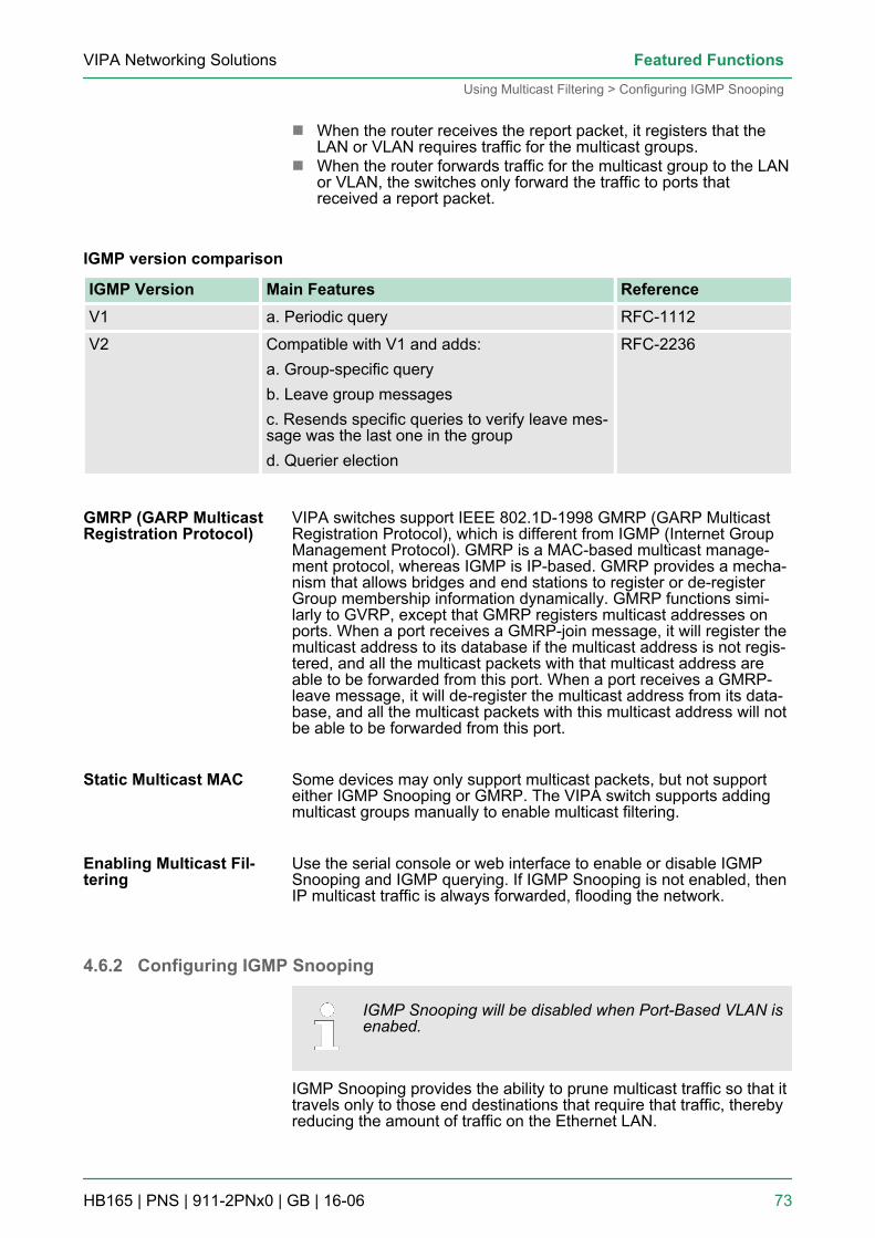
n When the router receives the report packet, it registers that theLAN or VLAN requires traffic for the multicast groups.
n When the router forwards traffic for the multicast group to the LANor VLAN, the switches only forward the traffic to ports thatreceived a report packet.
IGMP version comparison
IGMP Version Main Features ReferenceV1 a. Periodic query RFC-1112
V2 Compatible with V1 and adds:a. Group-specific queryb. Leave group messagesc. Resends specific queries to verify leave mes-sage was the last one in the groupd. Querier election
RFC-2236
VIPA switches support IEEE 802.1D-1998 GMRP (GARP MulticastRegistration Protocol), which is different from IGMP (Internet GroupManagement Protocol). GMRP is a MAC-based multicast manage-ment protocol, whereas IGMP is IP-based. GMRP provides a mecha-nism that allows bridges and end stations to register or de-registerGroup membership information dynamically. GMRP functions simi-larly to GVRP, except that GMRP registers multicast addresses onports. When a port receives a GMRP-join message, it will register themulticast address to its database if the multicast address is not regis-tered, and all the multicast packets with that multicast address areable to be forwarded from this port. When a port receives a GMRP-leave message, it will de-register the multicast address from its data-base, and all the multicast packets with this multicast address will notbe able to be forwarded from this port.
Some devices may only support multicast packets, but not supporteither IGMP Snooping or GMRP. The VIPA switch supports addingmulticast groups manually to enable multicast filtering.
Use the serial console or web interface to enable or disable IGMPSnooping and IGMP querying. If IGMP Snooping is not enabled, thenIP multicast traffic is always forwarded, flooding the network.
4.6.2 Configuring IGMP Snooping
IGMP Snooping will be disabled when Port-Based VLAN isenabed.
IGMP Snooping provides the ability to prune multicast traffic so that ittravels only to those end destinations that require that traffic, therebyreducing the amount of traffic on the Ethernet LAN.
GMRP (GARP MulticastRegistration Protocol)
Static Multicast MAC
Enabling Multicast Fil-tering
VIPA Networking Solutions Featured Functions
Using Multicast Filtering > Configuring IGMP Snooping
HB165 | PNS | 911-2PNx0 | GB | 16-06 73
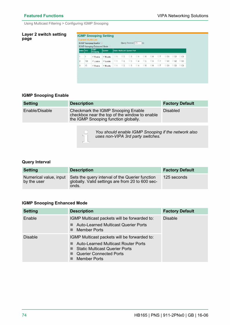
IGMP Snooping Enable
Setting Description Factory DefaultEnable/Disable Checkmark the IGMP Snooping Enable
checkbox near the top of the window to enablethe IGMP Snooping function globally.
Disabled
You should enable IGMP Snooping if the network alsouses non-VIPA 3rd party switches.
Query Interval
Setting Description Factory DefaultNumerical value, inputby the user
Sets the query interval of the Querier functionglobally. Valid settings are from 20 to 600 sec-onds.
125 seconds
IGMP Snooping Enhanced Mode
Setting Description Factory DefaultEnable IGMP Multicast packets will be forwarded to:
n Auto-Learned Multicast Querier Portsn Member Ports
Disable
Disable IGMP Multicast packets will be forwarded to:n Auto-Learned Multicast Router Portsn Static Multicast Querier Portsn Querier Connected Portsn Member Ports
Layer 2 switch settingpage
VIPA Networking SolutionsFeatured Functions
Using Multicast Filtering > Configuring IGMP Snooping
HB165 | PNS | 911-2PNx0 | GB | 16-06 74
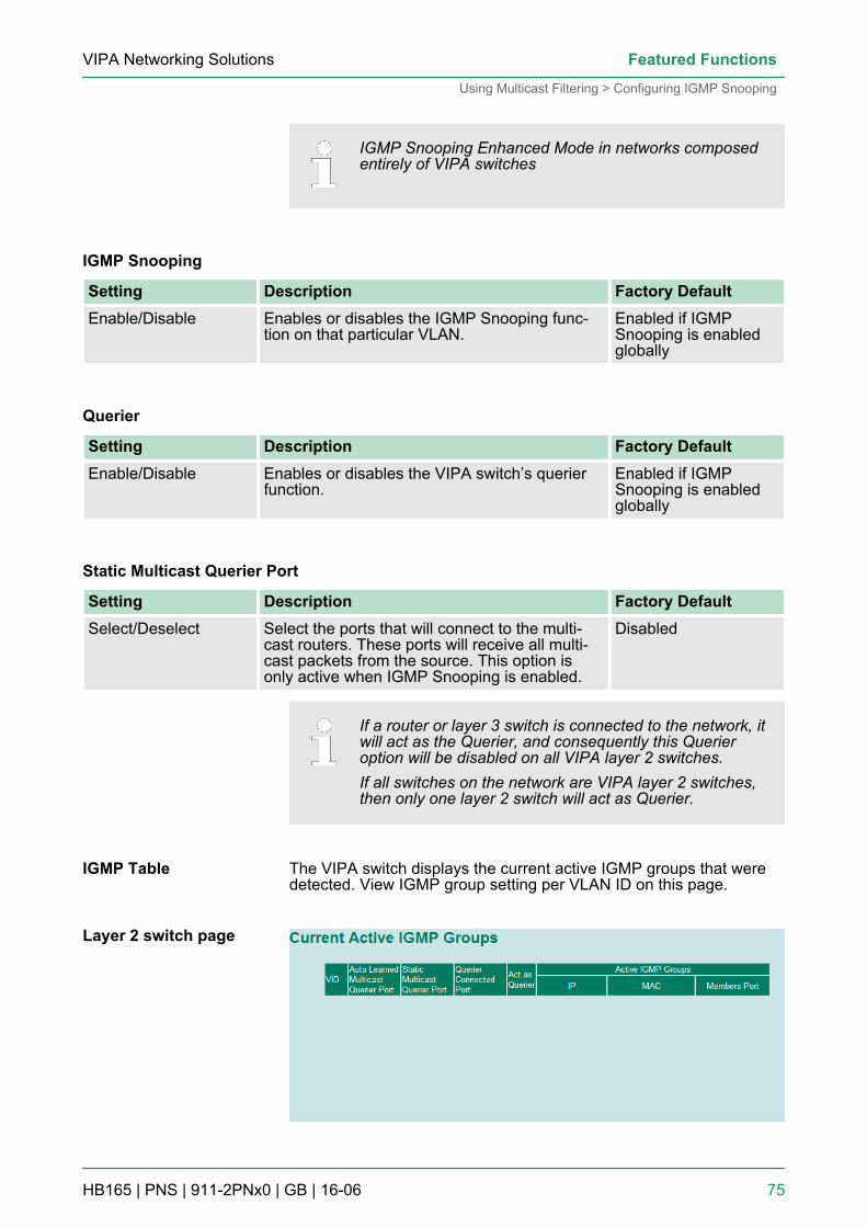
IGMP Snooping Enhanced Mode in networks composedentirely of VIPA switches
IGMP Snooping
Setting Description Factory DefaultEnable/Disable Enables or disables the IGMP Snooping func-
tion on that particular VLAN.Enabled if IGMPSnooping is enabledglobally
Querier
Setting Description Factory DefaultEnable/Disable Enables or disables the VIPA switch’s querier
function.Enabled if IGMPSnooping is enabledglobally
Static Multicast Querier Port
Setting Description Factory DefaultSelect/Deselect Select the ports that will connect to the multi-
cast routers. These ports will receive all multi-cast packets from the source. This option isonly active when IGMP Snooping is enabled.
Disabled
If a router or layer 3 switch is connected to the network, itwill act as the Querier, and consequently this Querieroption will be disabled on all VIPA layer 2 switches.If all switches on the network are VIPA layer 2 switches,then only one layer 2 switch will act as Querier.
The VIPA switch displays the current active IGMP groups that weredetected. View IGMP group setting per VLAN ID on this page.
IGMP Table
Layer 2 switch page
VIPA Networking Solutions Featured Functions
Using Multicast Filtering > Configuring IGMP Snooping
HB165 | PNS | 911-2PNx0 | GB | 16-06 75
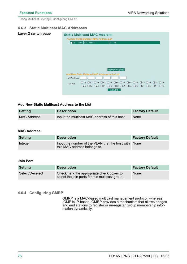
4.6.3 Static Multicast MAC Addresses
Add New Static Multicast Address to the List
Setting Description Factory DefaultMAC Address Input the multicast MAC address of this host. None
MAC Address
Setting Description Factory DefaultInteger Input the number of the VLAN that the host with
this MAC address belongs to.None
Join Port
Setting Description Factory DefaultSelect/Deselect Checkmark the appropriate check boxes to
select the join ports for this multicast group.None
4.6.4 Configuring GMRPGMRP is a MAC-based multicast management protocol, whereasIGMP is IP-based. GMRP provides a mechanism that allows bridgesand end stations to register or un-register Group membership infor-mation dynamically.
Layer 2 switch page
VIPA Networking SolutionsFeatured Functions
Using Multicast Filtering > Configuring GMRP
HB165 | PNS | 911-2PNx0 | GB | 16-06 76
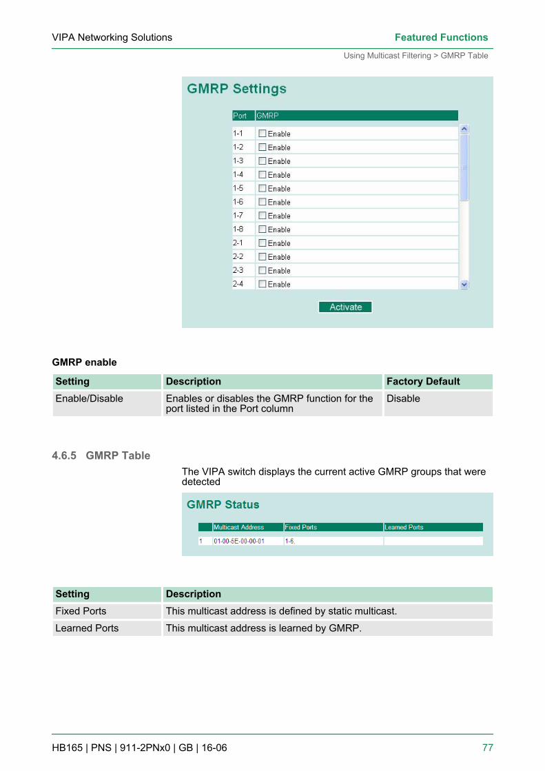
GMRP enable
Setting Description Factory DefaultEnable/Disable Enables or disables the GMRP function for the
port listed in the Port columnDisable
4.6.5 GMRP TableThe VIPA switch displays the current active GMRP groups that weredetected
Setting DescriptionFixed Ports This multicast address is defined by static multicast.
Learned Ports This multicast address is learned by GMRP.
VIPA Networking Solutions Featured Functions
Using Multicast Filtering > GMRP Table
HB165 | PNS | 911-2PNx0 | GB | 16-06 77
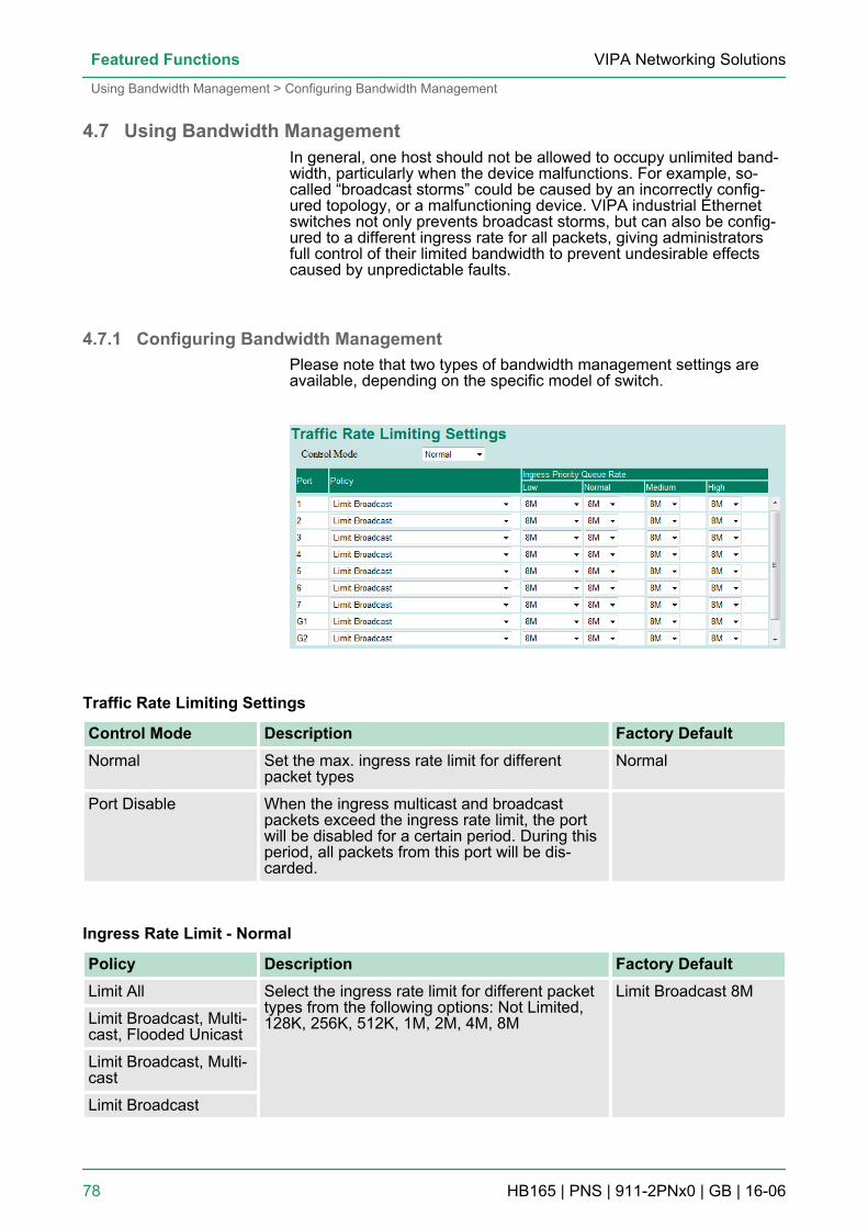
4.7 Using Bandwidth ManagementIn general, one host should not be allowed to occupy unlimited band-width, particularly when the device malfunctions. For example, so-called “broadcast storms” could be caused by an incorrectly config-ured topology, or a malfunctioning device. VIPA industrial Ethernetswitches not only prevents broadcast storms, but can also be config-ured to a different ingress rate for all packets, giving administratorsfull control of their limited bandwidth to prevent undesirable effectscaused by unpredictable faults.
4.7.1 Configuring Bandwidth ManagementPlease note that two types of bandwidth management settings areavailable, depending on the specific model of switch.
Traffic Rate Limiting Settings
Control Mode Description Factory DefaultNormal Set the max. ingress rate limit for different
packet typesNormal
Port Disable When the ingress multicast and broadcastpackets exceed the ingress rate limit, the portwill be disabled for a certain period. During thisperiod, all packets from this port will be dis-carded.
Ingress Rate Limit - Normal
Policy Description Factory DefaultLimit All Select the ingress rate limit for different packet
types from the following options: Not Limited,128K, 256K, 512K, 1M, 2M, 4M, 8M
Limit Broadcast 8M
Limit Broadcast, Multi-cast, Flooded Unicast
Limit Broadcast, Multi-cast
Limit Broadcast
VIPA Networking SolutionsFeatured Functions
Using Bandwidth Management > Configuring Bandwidth Management
HB165 | PNS | 911-2PNx0 | GB | 16-06 78
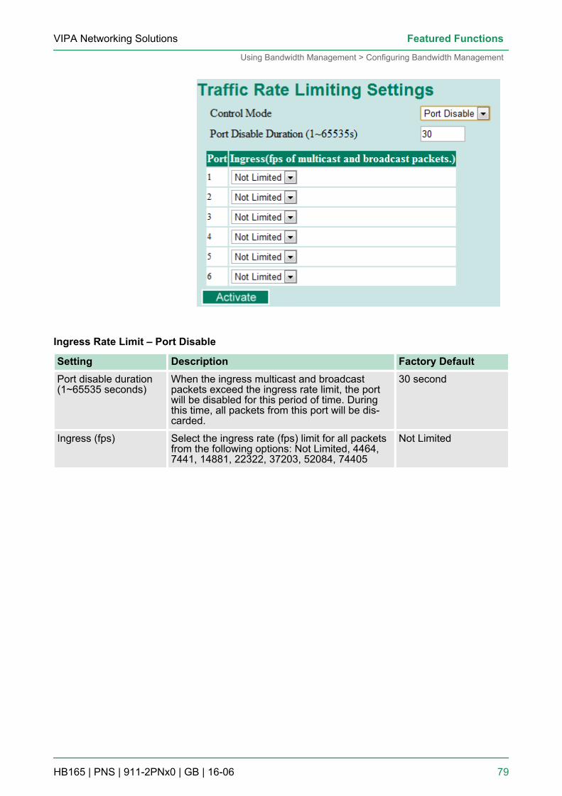
Ingress Rate Limit – Port Disable
Setting Description Factory DefaultPort disable duration(1~65535 seconds)
When the ingress multicast and broadcastpackets exceed the ingress rate limit, the portwill be disabled for this period of time. Duringthis time, all packets from this port will be dis-carded.
30 second
Ingress (fps) Select the ingress rate (fps) limit for all packetsfrom the following options: Not Limited, 4464,7441, 14881, 22322, 37203, 52084, 74405
Not Limited
VIPA Networking Solutions Featured Functions
Using Bandwidth Management > Configuring Bandwidth Management
HB165 | PNS | 911-2PNx0 | GB | 16-06 79
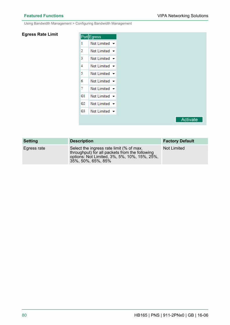
Setting Description Factory DefaultEgress rate Select the ingress rate limit (% of max.
throughput) for all packets from the followingoptions: Not Limited, 3%, 5%, 10%, 15%, 25%,35%, 50%, 65%, 85%
Not Limited
Egress Rate Limit
VIPA Networking SolutionsFeatured Functions
Using Bandwidth Management > Configuring Bandwidth Management
HB165 | PNS | 911-2PNx0 | GB | 16-06 80
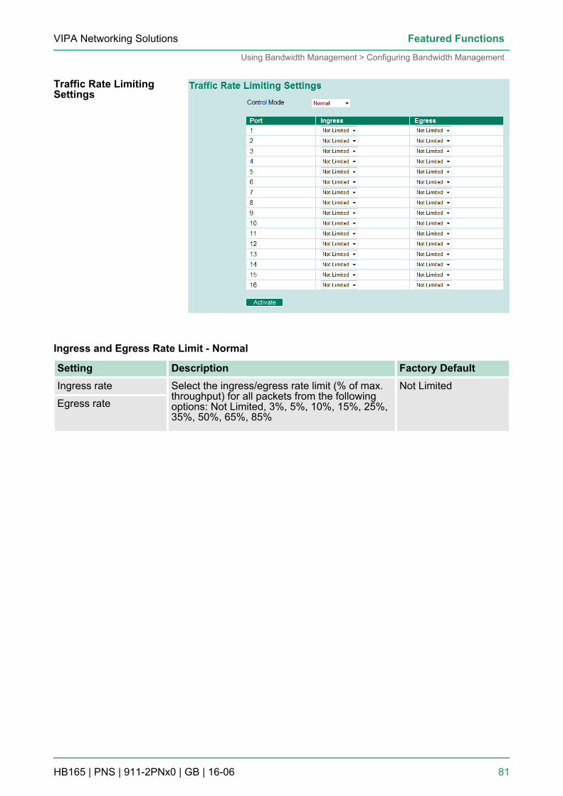
Ingress and Egress Rate Limit - Normal
Setting Description Factory DefaultIngress rate Select the ingress/egress rate limit (% of max.
throughput) for all packets from the followingoptions: Not Limited, 3%, 5%, 10%, 15%, 25%,35%, 50%, 65%, 85%
Not Limited
Egress rate
Traffic Rate LimitingSettings
VIPA Networking Solutions Featured Functions
Using Bandwidth Management > Configuring Bandwidth Management
HB165 | PNS | 911-2PNx0 | GB | 16-06 81
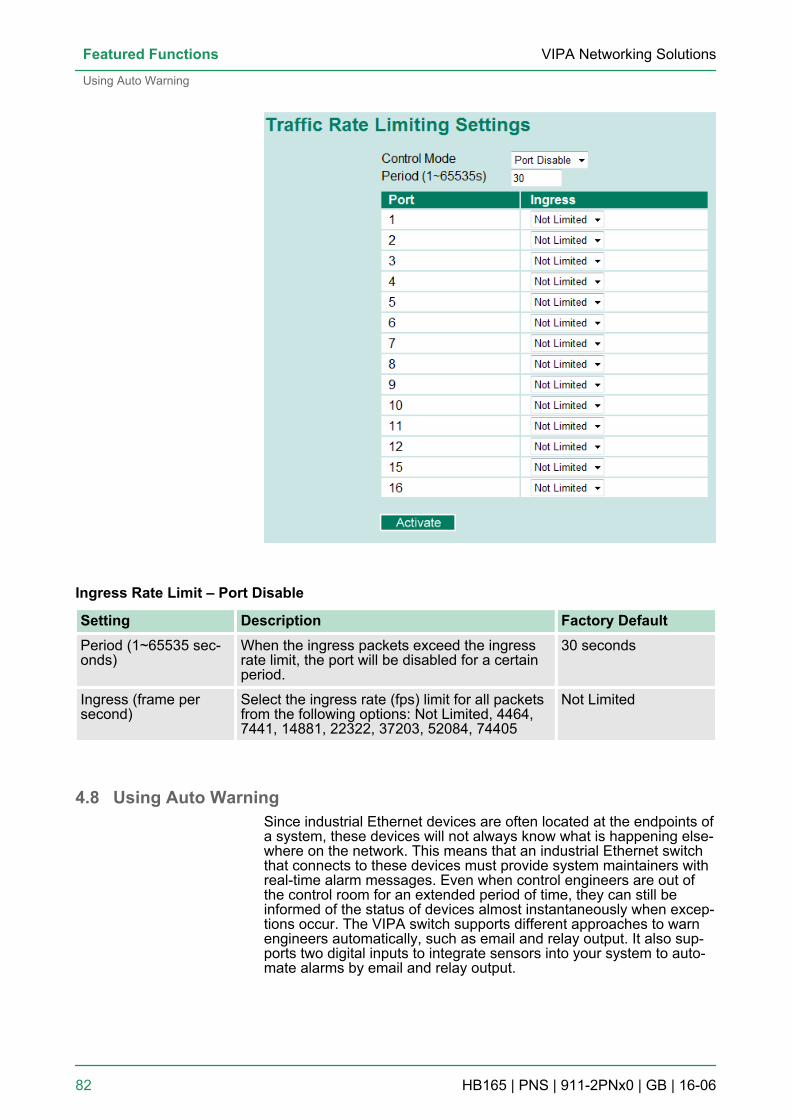
Ingress Rate Limit – Port Disable
Setting Description Factory DefaultPeriod (1~65535 sec-onds)
When the ingress packets exceed the ingressrate limit, the port will be disabled for a certainperiod.
30 seconds
Ingress (frame persecond)
Select the ingress rate (fps) limit for all packetsfrom the following options: Not Limited, 4464,7441, 14881, 22322, 37203, 52084, 74405
Not Limited
4.8 Using Auto WarningSince industrial Ethernet devices are often located at the endpoints ofa system, these devices will not always know what is happening else-where on the network. This means that an industrial Ethernet switchthat connects to these devices must provide system maintainers withreal-time alarm messages. Even when control engineers are out ofthe control room for an extended period of time, they can still beinformed of the status of devices almost instantaneously when excep-tions occur. The VIPA switch supports different approaches to warnengineers automatically, such as email and relay output. It also sup-ports two digital inputs to integrate sensors into your system to auto-mate alarms by email and relay output.
VIPA Networking SolutionsFeatured Functions
Using Auto Warning
HB165 | PNS | 911-2PNx0 | GB | 16-06 82
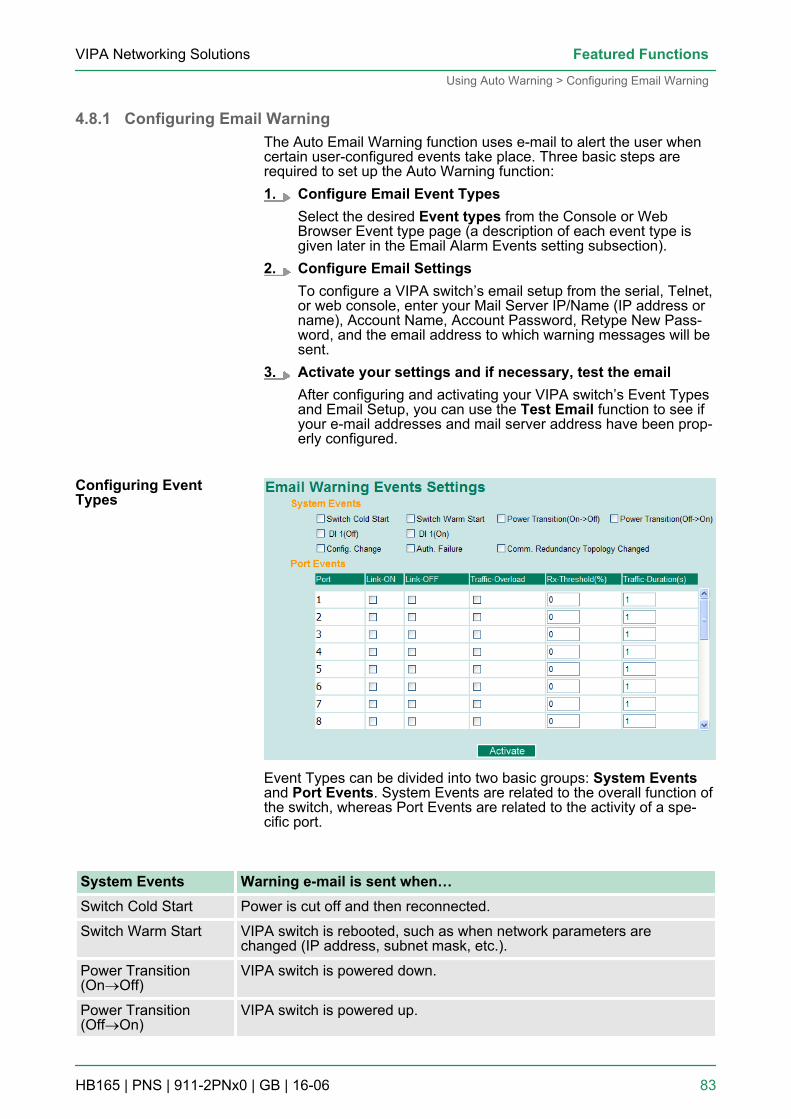
4.8.1 Configuring Email WarningThe Auto Email Warning function uses e-mail to alert the user whencertain user-configured events take place. Three basic steps arerequired to set up the Auto Warning function:1. Configure Email Event Types
Select the desired Event types from the Console or WebBrowser Event type page (a description of each event type isgiven later in the Email Alarm Events setting subsection).
2. Configure Email SettingsTo configure a VIPA switch’s email setup from the serial, Telnet,or web console, enter your Mail Server IP/Name (IP address orname), Account Name, Account Password, Retype New Pass-word, and the email address to which warning messages will besent.
3. Activate your settings and if necessary, test the emailAfter configuring and activating your VIPA switch’s Event Typesand Email Setup, you can use the Test Email function to see ifyour e-mail addresses and mail server address have been prop-erly configured.
Event Types can be divided into two basic groups: System Eventsand Port Events. System Events are related to the overall function ofthe switch, whereas Port Events are related to the activity of a spe-cific port.
System Events Warning e-mail is sent when…Switch Cold Start Power is cut off and then reconnected.
Switch Warm Start VIPA switch is rebooted, such as when network parameters arechanged (IP address, subnet mask, etc.).
Power Transition(On®Off)
VIPA switch is powered down.
Power Transition(Off®On)
VIPA switch is powered up.
Configuring EventTypes
VIPA Networking Solutions Featured Functions
Using Auto Warning > Configuring Email Warning
HB165 | PNS | 911-2PNx0 | GB | 16-06 83
System Events Warning e-mail is sent when…DI1/DI2 (On®Off) Digital Input 1/2 is triggered by on to off transition
DI1/DI2 (Off®On) Digital Input 1/2 is triggered by off to on transition
Configuration ChangeActivated
Any configuration item has been changed.
Authentication Failure An incorrect password was entered.
Comm. RedundancyTopology Changed
If any Spanning Tree Protocol switches have changed their position(applies only to the root of the tree). If the Master of the Turbo Ring haschanged or the backup path is activated.
Port Events Warning e-mail is sent when…Link-ON The port is connected to another device.
Link-OFF The port is disconnected (e.g., the cable is pulled out, or the opposingdevice shuts down).
Traffic-Overload The port’s traffic surpasses the Traffic-Threshold for that port (providedthis item is Enabled).
Traffic-Threshold (%) Enter a nonzero number if the port’s Traffic-Overload item is Enabled.
Traffic-Duration (sec.) A Traffic-Overload warning is sent every Traffic-Duration seconds if theaverage Traffic-Threshold is surpassed during that time period.
The Traffic-Overload, Traffic-Threshold (%), and Traffic-Duration (sec.) Port Event items are related. If you Enablethe Traffic-Overload event, then be sure to enter a non-zero Traffic-Threshold percentage, as well as a Traffic-Duration between 1 and 300 seconds.
The sender of warning e-mail messages will have the fol-lowing form:Managed-Redundant-Switch-00000@Switch_Locationwhere Managed-Redundant-Switch-00000 is the defaultSwitch Name, 00000 is the VIPA switch’s serial number,and Switch_Location is the default Server Location. Referto the Basic Settings section to see how to modify SwitchName and Switch Location.
VIPA Networking SolutionsFeatured Functions
Using Auto Warning > Configuring Email Warning
HB165 | PNS | 911-2PNx0 | GB | 16-06 84
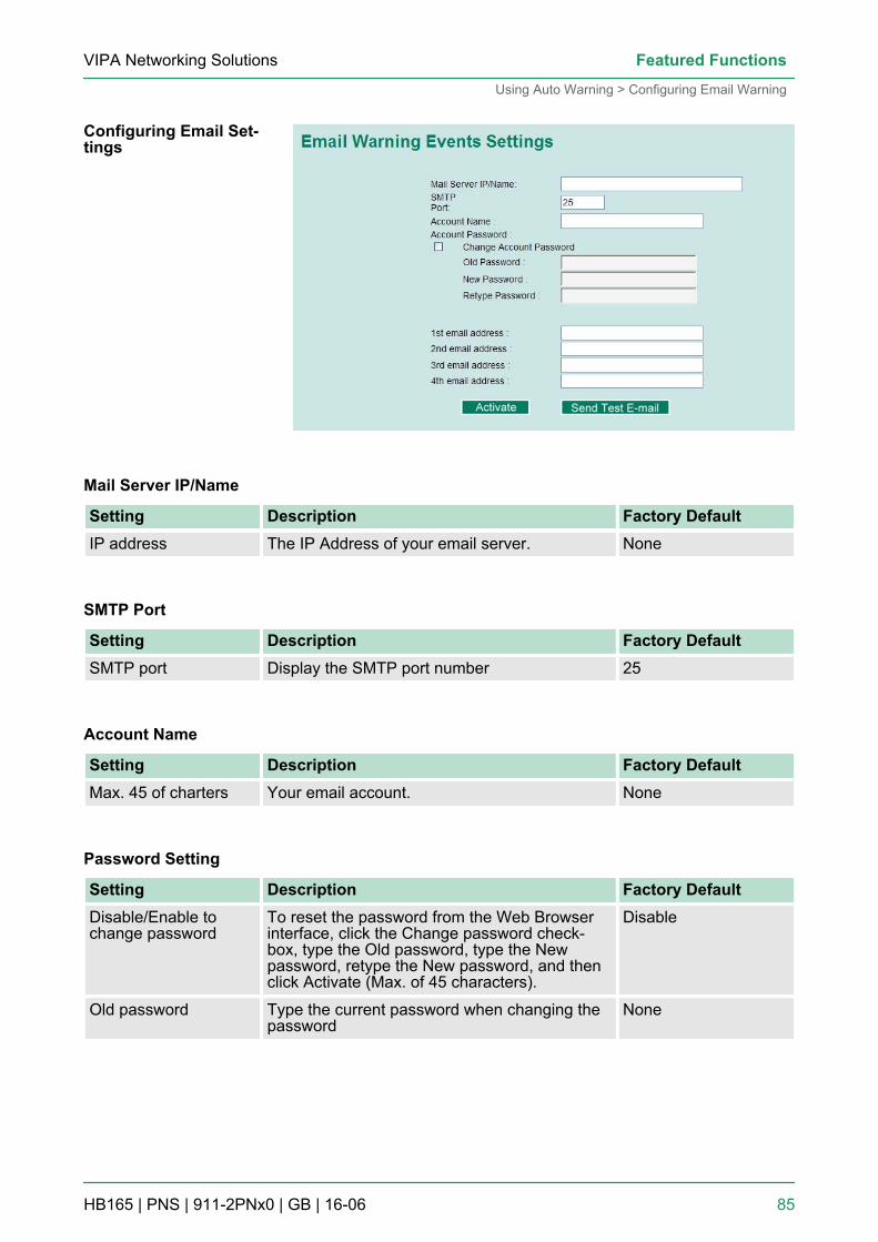
Mail Server IP/Name
Setting Description Factory DefaultIP address The IP Address of your email server. None
SMTP Port
Setting Description Factory DefaultSMTP port Display the SMTP port number 25
Account Name
Setting Description Factory DefaultMax. 45 of charters Your email account. None
Password Setting
Setting Description Factory DefaultDisable/Enable tochange password
To reset the password from the Web Browserinterface, click the Change password check-box, type the Old password, type the Newpassword, retype the New password, and thenclick Activate (Max. of 45 characters).
Disable
Old password Type the current password when changing thepassword
None
Configuring Email Set-tings
VIPA Networking Solutions Featured Functions
Using Auto Warning > Configuring Email Warning
HB165 | PNS | 911-2PNx0 | GB | 16-06 85
Setting Description Factory DefaultNew password Type new password when enabled to change
password; Max. 45 characters.None
Retype password If you type a new password in the Passwordfield, you will be required to retype the pass-word in the Retype new password field beforeupdating the new password.
None
Email Address
Setting Description Factory DefaultMax. of 30 characters You can set up to 4 email addresses to receive
alarm emails from the VIPA switch.None
After you complete the email settings, you should first click Activateto activate those settings, and then press the Send Test Email buttonto verify that the settings are correct.
Auto warning e-mail messages will be sent through anauthentication protected SMTP server that supports theCRAM-MD5, LOGIN, and PAIN methods of SASL (SimpleAuthentication and Security Layer) authentication mecha-nism.We strongly recommend not entering your Account Nameand Account Password if auto warning e-mail messagescan be delivered without using an authentication mecha-nism.
4.8.2 Configuring Relay WarningThe Auto Relay Warning function uses relay output to alert the userwhen certain user-configured events take place. There are two basicsteps required to set up the Relay Warning function:1. Configure Relay Event Types
Select the desired Event types from the Console or WebBrowser Event type page (a description of each event type isgiven later in the Relay Alarm Events setting subsection).
2. Activate your settingsAfter completing the configuration procedure, you will need toactivate your VIPA switch’s Relay Event Types.
Send Test Email
VIPA Networking SolutionsFeatured Functions
Using Auto Warning > Configuring Relay Warning
HB165 | PNS | 911-2PNx0 | GB | 16-06 86
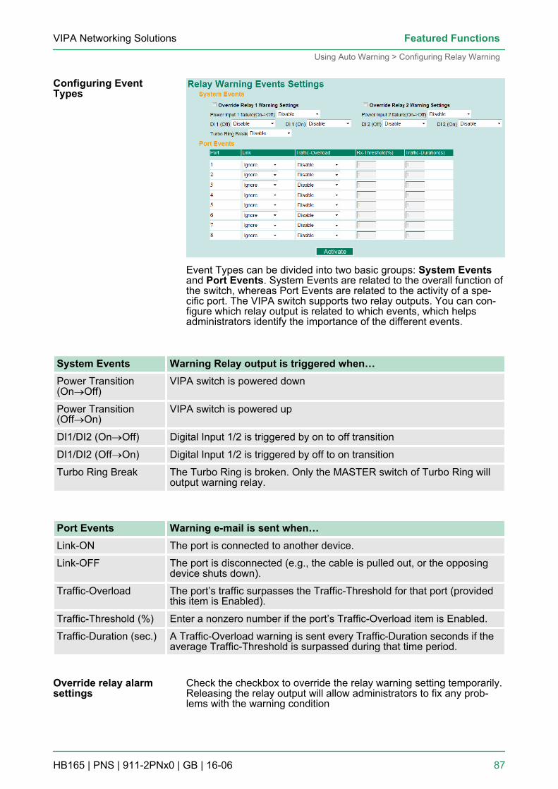
Event Types can be divided into two basic groups: System Eventsand Port Events. System Events are related to the overall function ofthe switch, whereas Port Events are related to the activity of a spe-cific port. The VIPA switch supports two relay outputs. You can con-figure which relay output is related to which events, which helpsadministrators identify the importance of the different events.
System Events Warning Relay output is triggered when…Power Transition(On®Off)
VIPA switch is powered down
Power Transition(Off®On)
VIPA switch is powered up
DI1/DI2 (On®Off) Digital Input 1/2 is triggered by on to off transition
DI1/DI2 (Off®On) Digital Input 1/2 is triggered by off to on transition
Turbo Ring Break The Turbo Ring is broken. Only the MASTER switch of Turbo Ring willoutput warning relay.
Port Events Warning e-mail is sent when…Link-ON The port is connected to another device.
Link-OFF The port is disconnected (e.g., the cable is pulled out, or the opposingdevice shuts down).
Traffic-Overload The port’s traffic surpasses the Traffic-Threshold for that port (providedthis item is Enabled).
Traffic-Threshold (%) Enter a nonzero number if the port’s Traffic-Overload item is Enabled.
Traffic-Duration (sec.) A Traffic-Overload warning is sent every Traffic-Duration seconds if theaverage Traffic-Threshold is surpassed during that time period.
Check the checkbox to override the relay warning setting temporarily.Releasing the relay output will allow administrators to fix any prob-lems with the warning condition
Configuring EventTypes
Override relay alarmsettings
VIPA Networking Solutions Featured Functions
Using Auto Warning > Configuring Relay Warning
HB165 | PNS | 911-2PNx0 | GB | 16-06 87
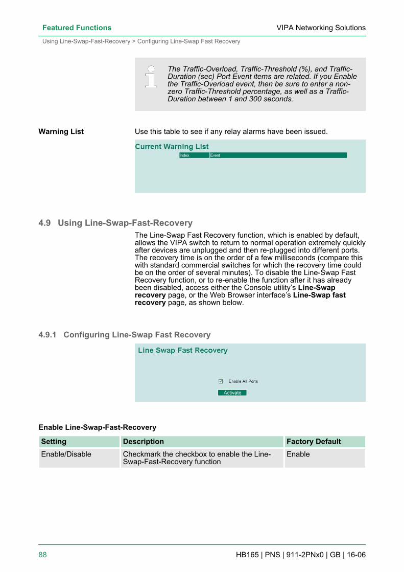
The Traffic-Overload, Traffic-Threshold (%), and Traffic-Duration (sec) Port Event items are related. If you Enablethe Traffic-Overload event, then be sure to enter a non-zero Traffic-Threshold percentage, as well as a Traffic-Duration between 1 and 300 seconds.
Use this table to see if any relay alarms have been issued.
4.9 Using Line-Swap-Fast-RecoveryThe Line-Swap Fast Recovery function, which is enabled by default,allows the VIPA switch to return to normal operation extremely quicklyafter devices are unplugged and then re-plugged into different ports.The recovery time is on the order of a few milliseconds (compare thiswith standard commercial switches for which the recovery time couldbe on the order of several minutes). To disable the Line-Swap FastRecovery function, or to re-enable the function after it has alreadybeen disabled, access either the Console utility’s Line-Swaprecovery page, or the Web Browser interface’s Line-Swap fastrecovery page, as shown below.
4.9.1 Configuring Line-Swap Fast Recovery
Enable Line-Swap-Fast-Recovery
Setting Description Factory DefaultEnable/Disable Checkmark the checkbox to enable the Line-
Swap-Fast-Recovery functionEnable
Warning List
VIPA Networking SolutionsFeatured Functions
Using Line-Swap-Fast-Recovery > Configuring Line-Swap Fast Recovery
HB165 | PNS | 911-2PNx0 | GB | 16-06 88
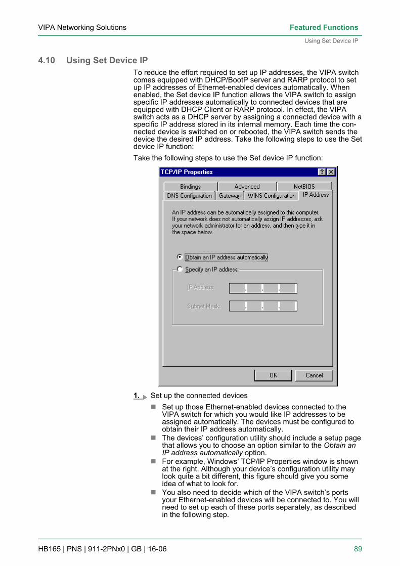
4.10 Using Set Device IPTo reduce the effort required to set up IP addresses, the VIPA switchcomes equipped with DHCP/BootP server and RARP protocol to setup IP addresses of Ethernet-enabled devices automatically. Whenenabled, the Set device IP function allows the VIPA switch to assignspecific IP addresses automatically to connected devices that areequipped with DHCP Client or RARP protocol. In effect, the VIPAswitch acts as a DHCP server by assigning a connected device with aspecific IP address stored in its internal memory. Each time the con-nected device is switched on or rebooted, the VIPA switch sends thedevice the desired IP address. Take the following steps to use the Setdevice IP function:Take the following steps to use the Set device IP function:
1. Set up the connected devicesn Set up those Ethernet-enabled devices connected to the
VIPA switch for which you would like IP addresses to beassigned automatically. The devices must be configured toobtain their IP address automatically.
n The devices’ configuration utility should include a setup pagethat allows you to choose an option similar to the Obtain anIP address automatically option.
n For example, Windows’ TCP/IP Properties window is shownat the right. Although your device’s configuration utility maylook quite a bit different, this figure should give you someidea of what to look for.
n You also need to decide which of the VIPA switch’s portsyour Ethernet-enabled devices will be connected to. You willneed to set up each of these ports separately, as describedin the following step.
VIPA Networking Solutions Featured Functions
Using Set Device IP
HB165 | PNS | 911-2PNx0 | GB | 16-06 89
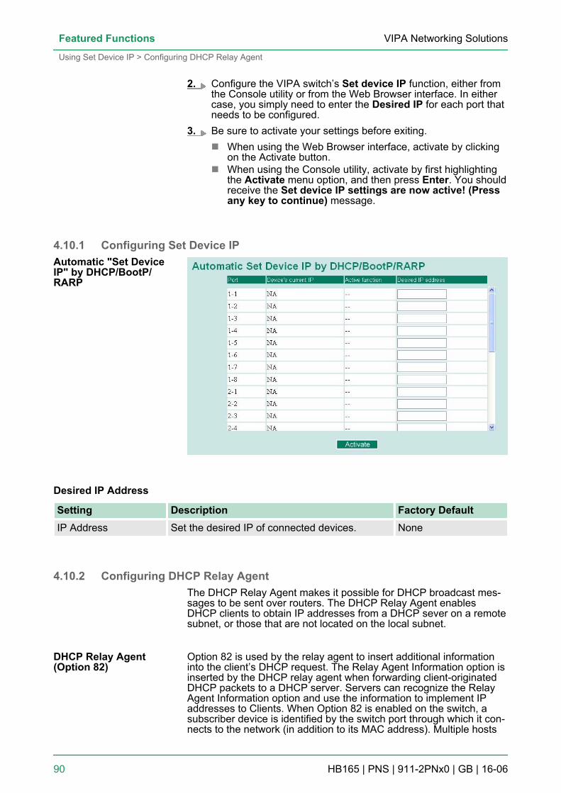
2. Configure the VIPA switch’s Set device IP function, either fromthe Console utility or from the Web Browser interface. In eithercase, you simply need to enter the Desired IP for each port thatneeds to be configured.
3. Be sure to activate your settings before exiting.n When using the Web Browser interface, activate by clicking
on the Activate button.n When using the Console utility, activate by first highlighting
the Activate menu option, and then press Enter. You shouldreceive the Set device IP settings are now active! (Pressany key to continue) message.
4.10.1 Configuring Set Device IP
Desired IP Address
Setting Description Factory DefaultIP Address Set the desired IP of connected devices. None
4.10.2 Configuring DHCP Relay AgentThe DHCP Relay Agent makes it possible for DHCP broadcast mes-sages to be sent over routers. The DHCP Relay Agent enablesDHCP clients to obtain IP addresses from a DHCP sever on a remotesubnet, or those that are not located on the local subnet.
Option 82 is used by the relay agent to insert additional informationinto the client’s DHCP request. The Relay Agent Information option isinserted by the DHCP relay agent when forwarding client-originatedDHCP packets to a DHCP server. Servers can recognize the RelayAgent Information option and use the information to implement IPaddresses to Clients. When Option 82 is enabled on the switch, asubscriber device is identified by the switch port through which it con-nects to the network (in addition to its MAC address). Multiple hosts
Automatic "Set DeviceIP" by DHCP/BootP/RARP
DHCP Relay Agent(Option 82)
VIPA Networking SolutionsFeatured Functions
Using Set Device IP > Configuring DHCP Relay Agent
HB165 | PNS | 911-2PNx0 | GB | 16-06 90
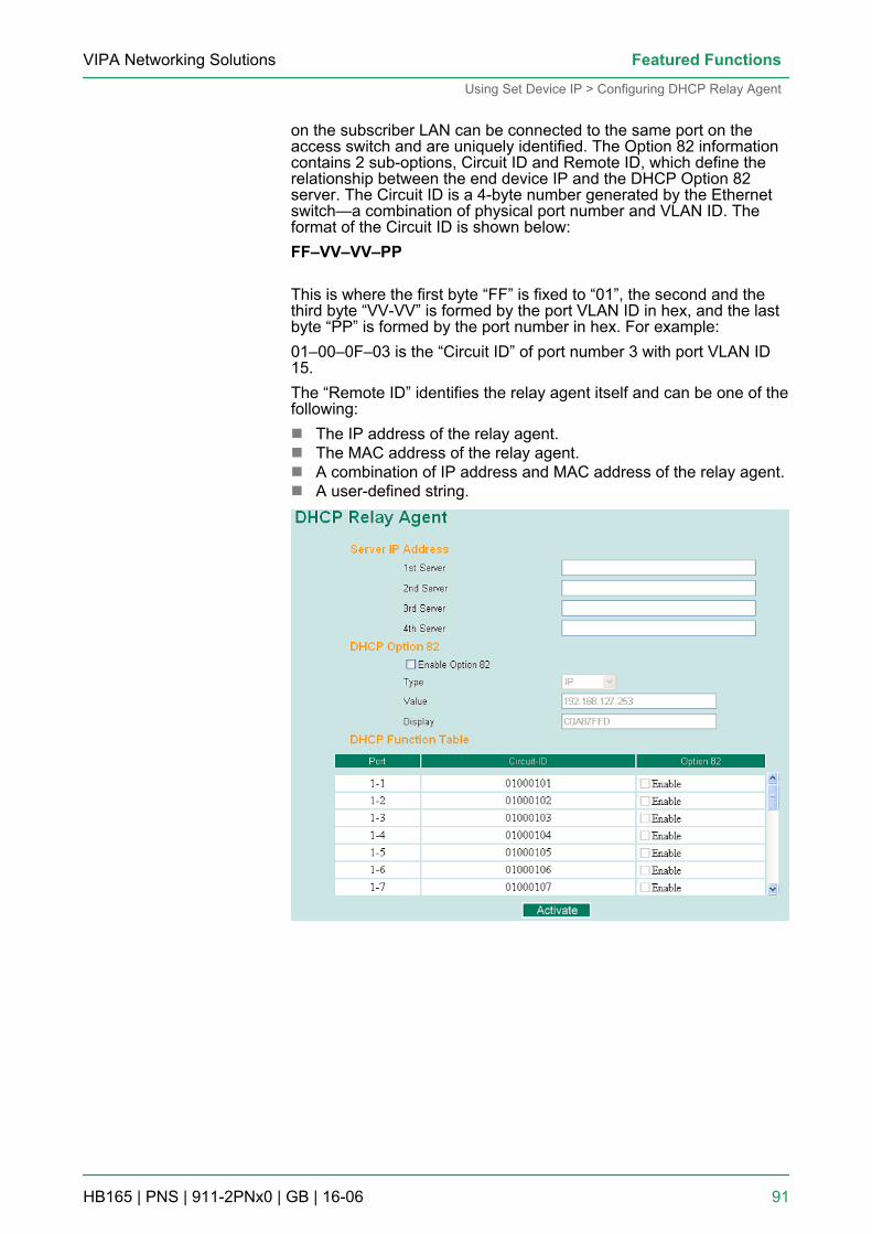
on the subscriber LAN can be connected to the same port on theaccess switch and are uniquely identified. The Option 82 informationcontains 2 sub-options, Circuit ID and Remote ID, which define therelationship between the end device IP and the DHCP Option 82server. The Circuit ID is a 4-byte number generated by the Ethernetswitch—a combination of physical port number and VLAN ID. Theformat of the Circuit ID is shown below:FF–VV–VV–PP
This is where the first byte “FF” is fixed to “01”, the second and thethird byte “VV-VV” is formed by the port VLAN ID in hex, and the lastbyte “PP” is formed by the port number in hex. For example:01–00–0F–03 is the “Circuit ID” of port number 3 with port VLAN ID15.The “Remote ID” identifies the relay agent itself and can be one of thefollowing:n The IP address of the relay agent.n The MAC address of the relay agent.n A combination of IP address and MAC address of the relay agent.n A user-defined string.
VIPA Networking Solutions Featured Functions
Using Set Device IP > Configuring DHCP Relay Agent
HB165 | PNS | 911-2PNx0 | GB | 16-06 91
1st Server
Setting Description Factory DefaultIP address for the 1stDHCP server
Assigns the IP address of the 1st DHCP serverthat the switch tries to access.
None
2nd Server
Setting Description Factory DefaultIP address for the 2ndDHCP server
Assigns the IP address of the 2nd DHCP serverthat the switch tries to access.
None
3rd Server
Setting Description Factory DefaultIP address for the 3rdDHCP server
Assigns the IP address of the 3rd DHCP serverthat the switch tries to access.
None
4th Server
Setting Description Factory DefaultIP address for the 4thDHCP server
Assigns the IP address of the 4th DHCP serverthat the switch tries to access.
None
Enable Option 82
Setting Description Factory DefaultEnable or Disable Enable or disable the DHCP Option 82 function. Disable
Type
Setting Description Factory DefaultIP Uses the switch’s IP address as the remote ID
sub.IP
MAC Uses the switch’s MAC address as the remoteID sub.
IP
Server IP Address
DHCP Option 82
VIPA Networking SolutionsFeatured Functions
Using Set Device IP > Configuring DHCP Relay Agent
HB165 | PNS | 911-2PNx0 | GB | 16-06 92
Setting Description Factory DefaultClient-ID Uses a combination of the switch’s MAC
address and IP address as the remote ID sub.IP
Other Uses the user-designated ID sub. IP
Value
Setting Description Factory DefaultMax. 12 characters Displays the value that was set. Complete this
field if type is set to Other.Switch IP address
Display
Setting Description Factory Defaultread-only The actual hexadecimal value configured in the
DHCP server for the Remote-ID. This value isautomatically generated according to the Valuefield. Users cannot modify it.
COA87FFD
Enable
Setting Description Factory DefaultEnable or Disable Enable or disable the DHCP Option 82 function
for this port.Disable
4.11 Using DiagnosisThe VIPA switch provides three important tools for administrators todiagnose network systems.
4.11.1 Mirror PortThe Mirror Port function can be used to monitor data being trans-mitted through a specific port. This is done by setting up another port(the mirror port) to receive the same data being transmitted from, orboth to and from, the port under observation. Using a mirror portallows the network administrator to sniff the observed port to keeptabs on network activity.
DHCP Function Table
VIPA Networking Solutions Featured Functions
Using Diagnosis > Mirror Port
HB165 | PNS | 911-2PNx0 | GB | 16-06 93
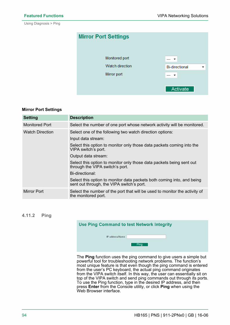
Mirror Port Settings
Setting DescriptionMonitored Port Select the number of one port whose network activity will be monitored.
Watch Direction Select one of the following two watch direction options:Input data stream:Select this option to monitor only those data packets coming into theVIPA switch’s port.Output data stream:Select this option to monitor only those data packets being sent outthrough the VIPA switch’s port.Bi-directional:Select this option to monitor data packets both coming into, and beingsent out through, the VIPA switch’s port.
Mirror Port Select the number of the port that will be used to monitor the activity ofthe monitored port.
4.11.2 Ping
The Ping function uses the ping command to give users a simple butpowerful tool for troubleshooting network problems. The function’smost unique feature is that even though the ping command is enteredfrom the user’s PC keyboard, the actual ping command originatesfrom the VIPA switch itself. In this way, the user can essentially sit ontop of the VIPA switch and send ping commands out through its ports.To use the Ping function, type in the desired IP address, and thenpress Enter from the Console utility, or click Ping when using theWeb Browser interface.
VIPA Networking SolutionsFeatured Functions
Using Diagnosis > Ping
HB165 | PNS | 911-2PNx0 | GB | 16-06 94
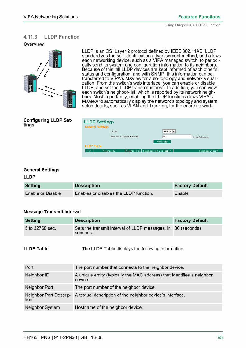
4.11.3 LLDP Function
LLDP is an OSI Layer 2 protocol defined by IEEE 802.11AB. LLDPstandardizes the self-identification advertisement method, and allowseach networking device, such as a VIPA managed switch, to periodi-cally send its system and configuration information to its neighbors.Because of this, all LLDP devices are kept informed of each other’sstatus and configuration, and with SNMP, this information can betransferred to VIPA’s MXview for auto-topology and network visuali-zation. From the switch’s web interface, you can enable or disableLLDP, and set the LLDP transmit interval. In addition, you can vieweach switch’s neighbor-list, which is reported by its network neigh-bors. Most importantly, enabling the LLDP function allows VIPA’sMXview to automatically display the network’s topology and systemsetup details, such as VLAN and Trunking, for the entire network.
LLDP
Setting Description Factory DefaultEnable or Disable Enables or disables the LLDP function. Enable
Message Transmit Interval
Setting Description Factory Default5 to 32768 sec. Sets the transmit interval of LLDP messages, in
seconds.30 (seconds)
The LLDP Table displays the following information:
Port The port number that connects to the neighbor device.
Neighbor ID A unique entity (typically the MAC address) that identifies a neighbordevice.
Neighbor Port The port number of the neighbor device.
Neighbor Port Descrip-tion
A textual description of the neighbor device’s interface.
Neighbor System Hostname of the neighbor device.
Overview
Configuring LLDP Set-tings
General Settings
LLDP Table
VIPA Networking Solutions Featured Functions
Using Diagnosis > LLDP Function
HB165 | PNS | 911-2PNx0 | GB | 16-06 95
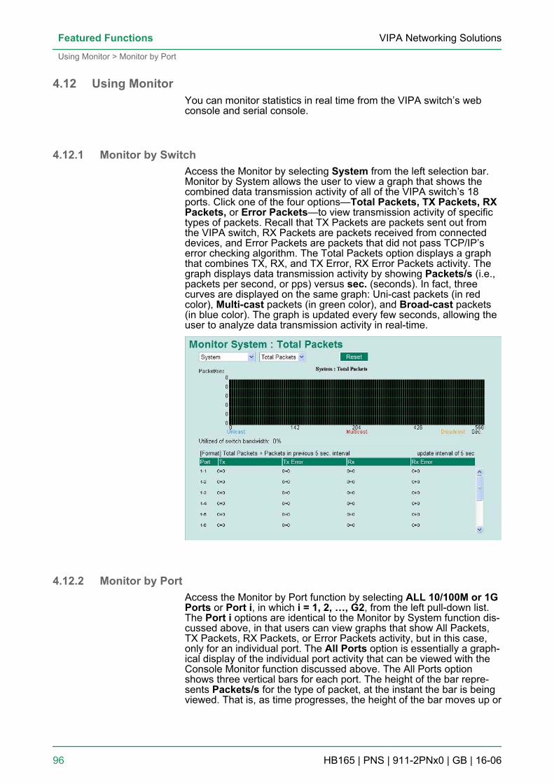
4.12 Using MonitorYou can monitor statistics in real time from the VIPA switch’s webconsole and serial console.
4.12.1 Monitor by SwitchAccess the Monitor by selecting System from the left selection bar.Monitor by System allows the user to view a graph that shows thecombined data transmission activity of all of the VIPA switch’s 18ports. Click one of the four options—Total Packets, TX Packets, RXPackets, or Error Packets—to view transmission activity of specifictypes of packets. Recall that TX Packets are packets sent out fromthe VIPA switch, RX Packets are packets received from connecteddevices, and Error Packets are packets that did not pass TCP/IP’serror checking algorithm. The Total Packets option displays a graphthat combines TX, RX, and TX Error, RX Error Packets activity. Thegraph displays data transmission activity by showing Packets/s (i.e.,packets per second, or pps) versus sec. (seconds). In fact, threecurves are displayed on the same graph: Uni-cast packets (in redcolor), Multi-cast packets (in green color), and Broad-cast packets(in blue color). The graph is updated every few seconds, allowing theuser to analyze data transmission activity in real-time.
4.12.2 Monitor by PortAccess the Monitor by Port function by selecting ALL 10/100M or 1GPorts or Port i, in which i = 1, 2, …, G2, from the left pull-down list.The Port i options are identical to the Monitor by System function dis-cussed above, in that users can view graphs that show All Packets,TX Packets, RX Packets, or Error Packets activity, but in this case,only for an individual port. The All Ports option is essentially a graph-ical display of the individual port activity that can be viewed with theConsole Monitor function discussed above. The All Ports optionshows three vertical bars for each port. The height of the bar repre-sents Packets/s for the type of packet, at the instant the bar is beingviewed. That is, as time progresses, the height of the bar moves up or
VIPA Networking SolutionsFeatured Functions
Using Monitor > Monitor by Port
HB165 | PNS | 911-2PNx0 | GB | 16-06 96
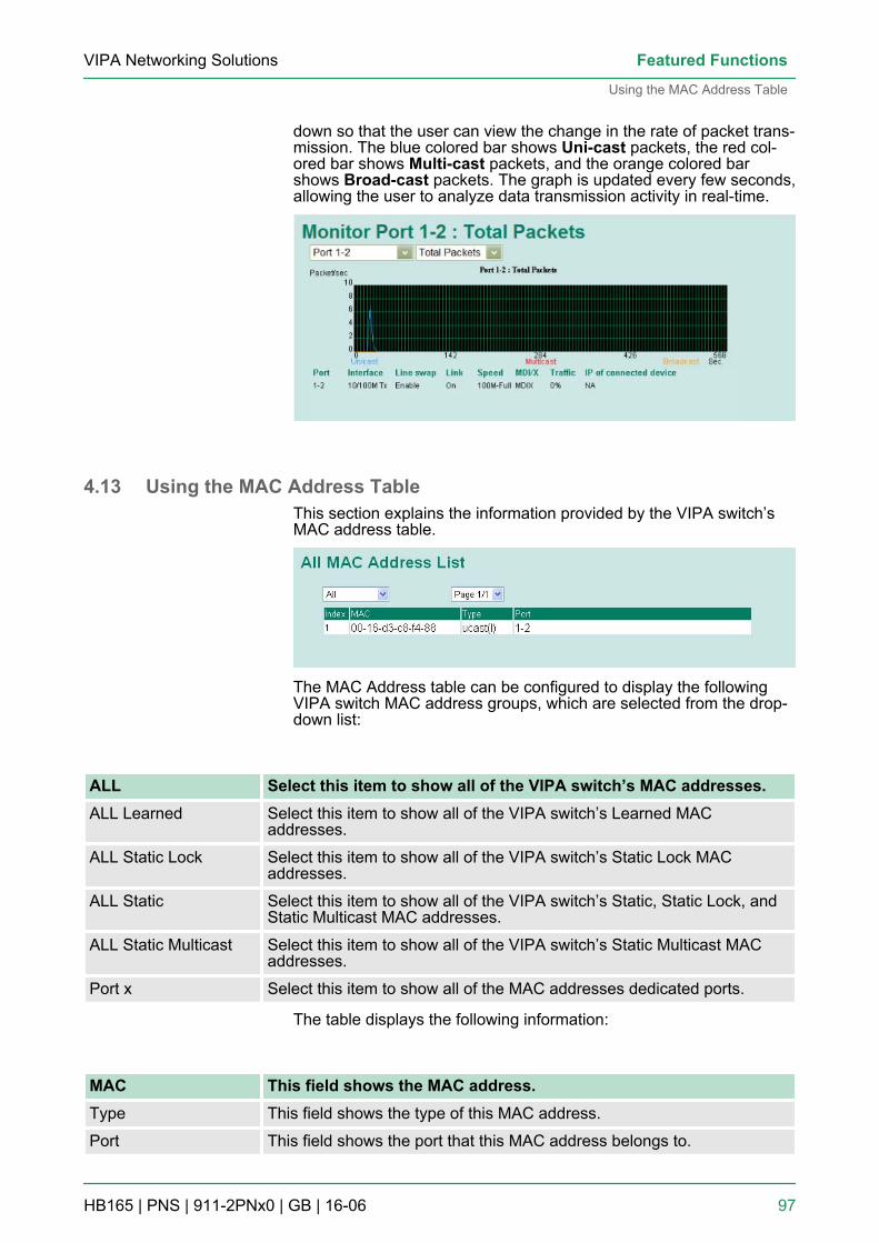
down so that the user can view the change in the rate of packet trans-mission. The blue colored bar shows Uni-cast packets, the red col-ored bar shows Multi-cast packets, and the orange colored barshows Broad-cast packets. The graph is updated every few seconds,allowing the user to analyze data transmission activity in real-time.
4.13 Using the MAC Address TableThis section explains the information provided by the VIPA switch’sMAC address table.
The MAC Address table can be configured to display the followingVIPA switch MAC address groups, which are selected from the drop-down list:
ALL Select this item to show all of the VIPA switch’s MAC addresses.ALL Learned Select this item to show all of the VIPA switch’s Learned MAC
addresses.
ALL Static Lock Select this item to show all of the VIPA switch’s Static Lock MACaddresses.
ALL Static Select this item to show all of the VIPA switch’s Static, Static Lock, andStatic Multicast MAC addresses.
ALL Static Multicast Select this item to show all of the VIPA switch’s Static Multicast MACaddresses.
Port x Select this item to show all of the MAC addresses dedicated ports.
The table displays the following information:
MAC This field shows the MAC address.Type This field shows the type of this MAC address.
Port This field shows the port that this MAC address belongs to.
VIPA Networking Solutions Featured Functions
Using the MAC Address Table
HB165 | PNS | 911-2PNx0 | GB | 16-06 97
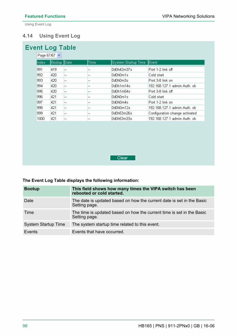
4.14 Using Event Log
The Event Log Table displays the following information:
Bootup This field shows how many times the VIPA switch has beenrebooted or cold started.
Date The date is updated based on how the current date is set in the BasicSetting page.
Time The time is updated based on how the current time is set in the BasicSetting page.
System Startup Time The system startup time related to this event.
Events Events that have occurred.
VIPA Networking SolutionsFeatured Functions
Using Event Log
HB165 | PNS | 911-2PNx0 | GB | 16-06 98
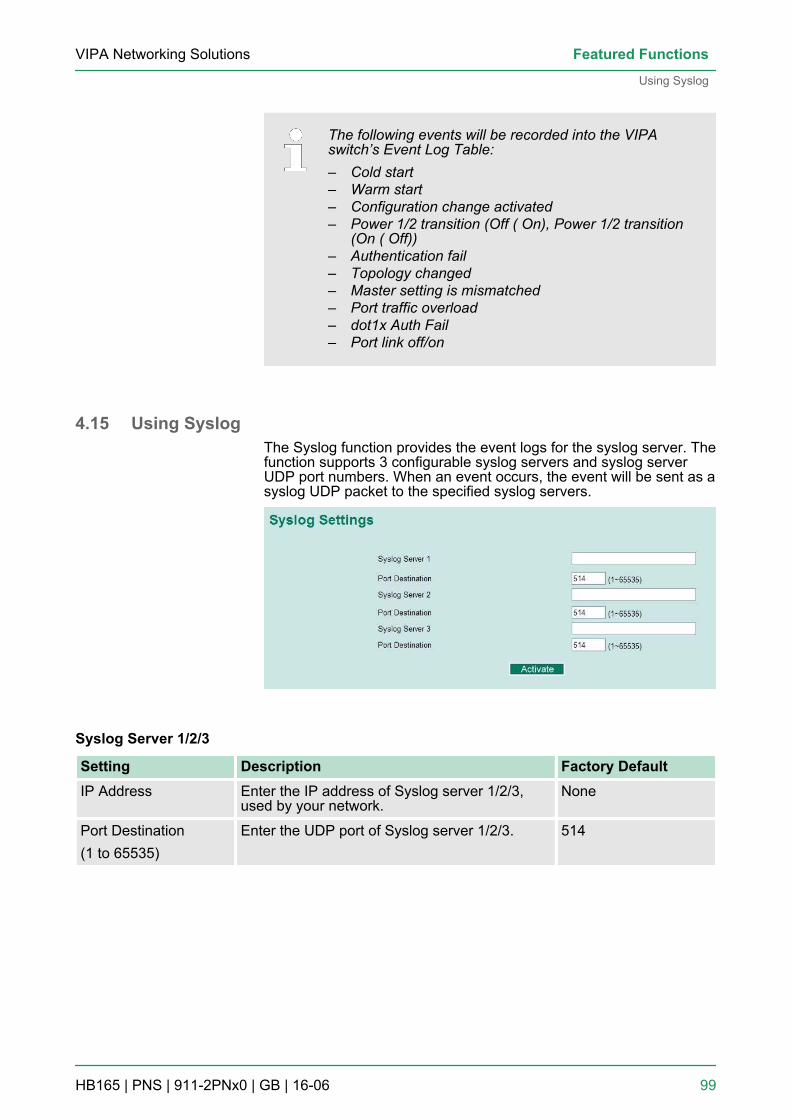
The following events will be recorded into the VIPAswitch’s Event Log Table:– Cold start– Warm start– Configuration change activated– Power 1/2 transition (Off ( On), Power 1/2 transition
(On ( Off))– Authentication fail– Topology changed– Master setting is mismatched– Port traffic overload– dot1x Auth Fail– Port link off/on
4.15 Using SyslogThe Syslog function provides the event logs for the syslog server. Thefunction supports 3 configurable syslog servers and syslog serverUDP port numbers. When an event occurs, the event will be sent as asyslog UDP packet to the specified syslog servers.
Syslog Server 1/2/3
Setting Description Factory DefaultIP Address Enter the IP address of Syslog server 1/2/3,
used by your network.None
Port Destination(1 to 65535)
Enter the UDP port of Syslog server 1/2/3. 514
VIPA Networking Solutions Featured Functions
Using Syslog
HB165 | PNS | 911-2PNx0 | GB | 16-06 99
The following events will be recorded into the VIPAswitch’s Event Log table, and will then be sent to thespecified Syslog Server:– Cold start– Warm start– Configuration change activated– Power 1/2 transition (Off ( On), Power 1/2 transition
(On ( Off))– Authentication fail– Topology changed– Master setting is mismatched– Port traffic overload– dot1x Auth Fail– Port link off/on
VIPA Networking SolutionsFeatured Functions
Using Syslog
HB165 | PNS | 911-2PNx0 | GB | 16-06 100
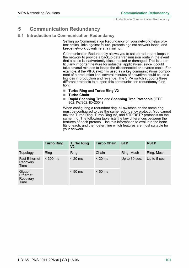
5 Communication Redundancy5.1 Introduction to Communication Redundancy
Setting up Communication Redundancy on your network helps pro-tect critical links against failure, protects against network loops, andkeeps network downtime at a minimum.Communication Redundancy allows you to set up redundant loops inthe network to provide a backup data transmission route in the eventthat a cable is inadvertently disconnected or damaged. This is a par-ticularly important feature for industrial applications, since it couldtake several minutes to locate the disconnected or severed cable. Forexample, if the VIPA switch is used as a key communications compo-nent of a production line, several minutes of downtime could cause abig loss in production and revenue. The VIPA switch supports threedifferent protocols to support this communication redundancy func-tion:n Turbo Ring and Turbo Ring V2n Turbo Chainn Rapid Spanning Tree and Spanning Tree Protocols (IEEE
802.1W/802.1D-2004)When configuring a redundant ring, all switches on the same ringmust be configured to use the same redundancy protocol. You cannotmix the Turbo Ring, Turbo Ring V2, and STP/RSTP protocols on thesame ring. The following table lists the key differences between thefeatures of each protocol. Use this information to evaluate the bene-fits of each, and then determine which features are most suitable foryour network.
Turbo Ring Turbo RingV2
Turbo Chain STP RSTP
Topology Ring Ring Chain Ring, Mesh Ring, Mesh
Fast EthernetRecoveryTime
< 300 ms < 20 ms < 20 ms Up to 30 sec. Up to 5 sec.
GigabitEthernetRecoveryTime
< 50 ms < 50 ms
VIPA Networking Solutions Communication Redundancy
Introduction to Communication Redundancy
HB165 | PNS | 911-2PNx0 | GB | 16-06 101
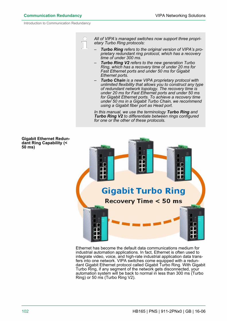
All of VIPA’s managed switches now support three propri-etary Turbo Ring protocols:– Turbo Ring refers to the original version of VIPA’s pro-
prietary redundant ring protocol, which has a recoverytime of under 300 ms.
– Turbo Ring V2 refers to the new generation TurboRing, which has a recovery time of under 20 ms forFast Ethernet ports and under 50 ms for GigabitEthernet ports.
– Turbo Chain is a new VIPA proprietary protocol withunlimited flexibility that allows you to construct any typeof redundant network topology. The recovery time isunder 20 ms for Fast Ethernet ports and under 50 msfor Gigabit Ethernet ports. To achieve a recovery timeunder 50 ms in a Gigabit Turbo Chain, we recommendusing a Gigabit fiber port as Head port.
In this manual, we use the terminology Turbo Ring andTurbo Ring V2 to differentiate between rings configuredfor one or the other of these protocols.
Ethernet has become the default data communications medium forindustrial automation applications. In fact, Ethernet is often used tointegrate video, voice, and high-rate industrial application data trans-fers into one network. VIPA switches come equipped with a redun-dant Gigabit Ethernet protocol called Gigabit Turbo Ring. With GigabitTurbo Ring, if any segment of the network gets disconnected, yourautomation system will be back to normal in less than 300 ms (TurboRing) or 50 ms (Turbo Ring V2).
Gigabit Ethernet Redun-dant Ring Capability (<50 ms)
VIPA Networking SolutionsCommunication Redundancy
Introduction to Communication Redundancy
HB165 | PNS | 911-2PNx0 | GB | 16-06 102
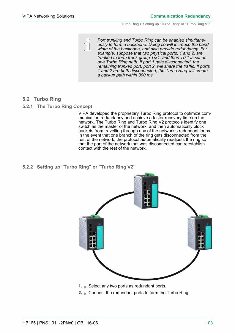
Port trunking and Turbo Ring can be enabled simultane-ously to form a backbone. Doing so will increase the band-width of the backbone, and also provide redundancy. Forexample, suppose that two physical ports, 1 and 2, aretrunked to form trunk group Trk1, and then Trk1 is set asone Turbo Ring path. If port 1 gets disconnected, theremaining trunked port, port 2, will share the traffic. If ports1 and 2 are both disconnected, the Turbo Ring will createa backup path within 300 ms.
5.2 Turbo Ring5.2.1 The Turbo Ring Concept
VIPA developed the proprietary Turbo Ring protocol to optimize com-munication redundancy and achieve a faster recovery time on thenetwork. The Turbo Ring and Turbo Ring V2 protocols identify oneswitch as the master of the network, and then automatically blockpackets from travelling through any of the network’s redundant loops.In the event that one branch of the ring gets disconnected from therest of the network, the protocol automatically readjusts the ring sothat the part of the network that was disconnected can reestablishcontact with the rest of the network.
5.2.2 Setting up "Turbo Ring" or "Turbo Ring V2"
1. Select any two ports as redundant ports.2. Connect the redundant ports to form the Turbo Ring.
VIPA Networking Solutions Communication Redundancy
Turbo Ring > Setting up "Turbo Ring" or "Turbo Ring V2"
HB165 | PNS | 911-2PNx0 | GB | 16-06 103
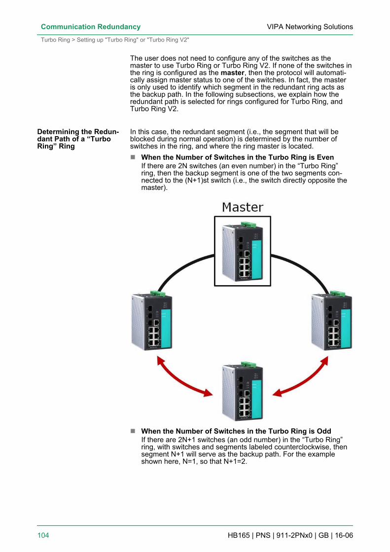
The user does not need to configure any of the switches as themaster to use Turbo Ring or Turbo Ring V2. If none of the switches inthe ring is configured as the master, then the protocol will automati-cally assign master status to one of the switches. In fact, the masteris only used to identify which segment in the redundant ring acts asthe backup path. In the following subsections, we explain how theredundant path is selected for rings configured for Turbo Ring, andTurbo Ring V2.
In this case, the redundant segment (i.e., the segment that will beblocked during normal operation) is determined by the number ofswitches in the ring, and where the ring master is located.n When the Number of Switches in the Turbo Ring is Even
If there are 2N switches (an even number) in the “Turbo Ring”ring, then the backup segment is one of the two segments con-nected to the (N+1)st switch (i.e., the switch directly opposite themaster).
n When the Number of Switches in the Turbo Ring is OddIf there are 2N+1 switches (an odd number) in the “Turbo Ring”ring, with switches and segments labeled counterclockwise, thensegment N+1 will serve as the backup path. For the exampleshown here, N=1, so that N+1=2.
Determining the Redun-dant Path of a “TurboRing” Ring
VIPA Networking SolutionsCommunication Redundancy
Turbo Ring > Setting up "Turbo Ring" or "Turbo Ring V2"
HB165 | PNS | 911-2PNx0 | GB | 16-06 104
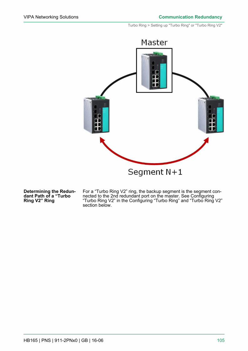
For a “Turbo Ring V2” ring, the backup segment is the segment con-nected to the 2nd redundant port on the master. See Configuring“Turbo Ring V2” in the Configuring “Turbo Ring” and “Turbo Ring V2”section below.
Determining the Redun-dant Path of a “TurboRing V2” Ring
VIPA Networking Solutions Communication Redundancy
Turbo Ring > Setting up "Turbo Ring" or "Turbo Ring V2"
HB165 | PNS | 911-2PNx0 | GB | 16-06 105
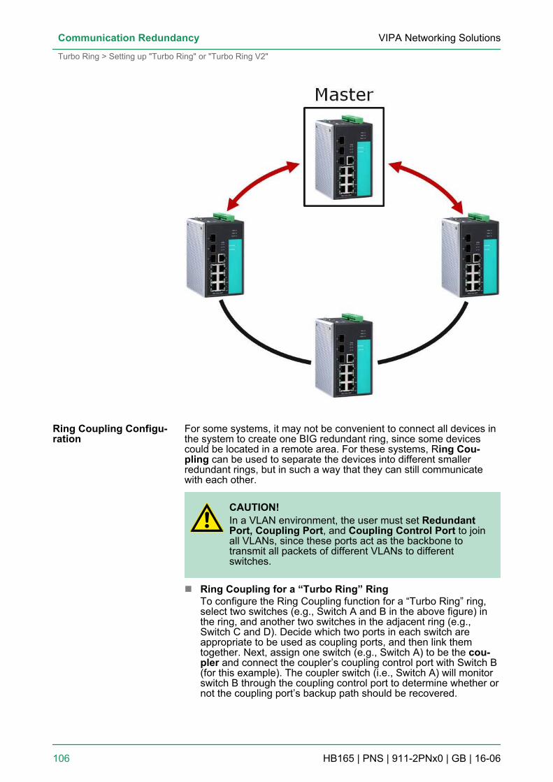
For some systems, it may not be convenient to connect all devices inthe system to create one BIG redundant ring, since some devicescould be located in a remote area. For these systems, Ring Cou-pling can be used to separate the devices into different smallerredundant rings, but in such a way that they can still communicatewith each other.
CAUTION!In a VLAN environment, the user must set RedundantPort, Coupling Port, and Coupling Control Port to joinall VLANs, since these ports act as the backbone totransmit all packets of different VLANs to differentswitches.
n Ring Coupling for a “Turbo Ring” RingTo configure the Ring Coupling function for a “Turbo Ring” ring,select two switches (e.g., Switch A and B in the above figure) inthe ring, and another two switches in the adjacent ring (e.g.,Switch C and D). Decide which two ports in each switch areappropriate to be used as coupling ports, and then link themtogether. Next, assign one switch (e.g., Switch A) to be the cou-pler and connect the coupler’s coupling control port with Switch B(for this example). The coupler switch (i.e., Switch A) will monitorswitch B through the coupling control port to determine whether ornot the coupling port’s backup path should be recovered.
Ring Coupling Configu-ration
VIPA Networking SolutionsCommunication Redundancy
Turbo Ring > Setting up "Turbo Ring" or "Turbo Ring V2"
HB165 | PNS | 911-2PNx0 | GB | 16-06 106
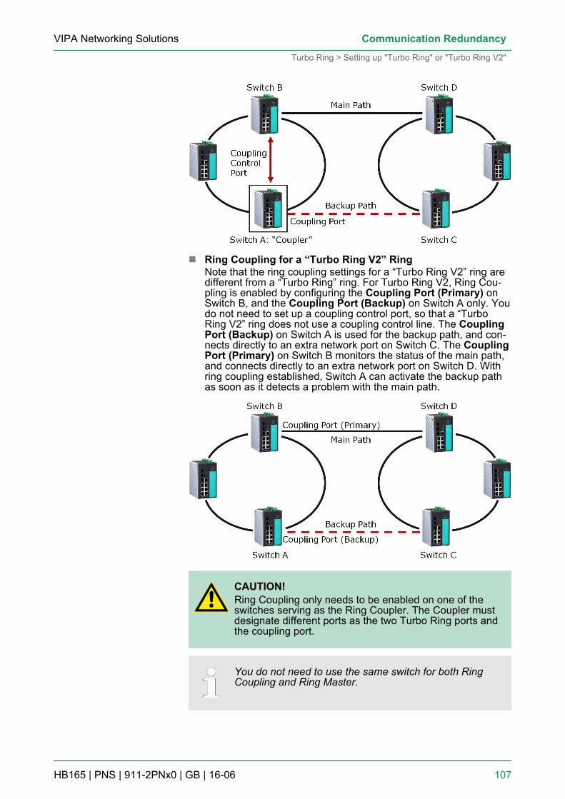
n Ring Coupling for a “Turbo Ring V2” RingNote that the ring coupling settings for a “Turbo Ring V2” ring aredifferent from a “Turbo Ring” ring. For Turbo Ring V2, Ring Cou-pling is enabled by configuring the Coupling Port (Primary) onSwitch B, and the Coupling Port (Backup) on Switch A only. Youdo not need to set up a coupling control port, so that a “TurboRing V2” ring does not use a coupling control line. The CouplingPort (Backup) on Switch A is used for the backup path, and con-nects directly to an extra network port on Switch C. The CouplingPort (Primary) on Switch B monitors the status of the main path,and connects directly to an extra network port on Switch D. Withring coupling established, Switch A can activate the backup pathas soon as it detects a problem with the main path.
CAUTION!Ring Coupling only needs to be enabled on one of theswitches serving as the Ring Coupler. The Coupler mustdesignate different ports as the two Turbo Ring ports andthe coupling port.
You do not need to use the same switch for both RingCoupling and Ring Master.
VIPA Networking Solutions Communication Redundancy
Turbo Ring > Setting up "Turbo Ring" or "Turbo Ring V2"
HB165 | PNS | 911-2PNx0 | GB | 16-06 107
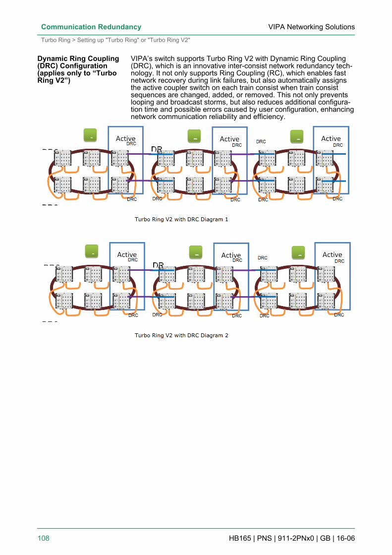
VIPA’s switch supports Turbo Ring V2 with Dynamic Ring Coupling(DRC), which is an innovative inter-consist network redundancy tech-nology. It not only supports Ring Coupling (RC), which enables fastnetwork recovery during link failures, but also automatically assignsthe active coupler switch on each train consist when train consistsequences are changed, added, or removed. This not only preventslooping and broadcast storms, but also reduces additional configura-tion time and possible errors caused by user configuration, enhancingnetwork communication reliability and efficiency.
Dynamic Ring Coupling(DRC) Configuration(applies only to “TurboRing V2”)
VIPA Networking SolutionsCommunication Redundancy
Turbo Ring > Setting up "Turbo Ring" or "Turbo Ring V2"
HB165 | PNS | 911-2PNx0 | GB | 16-06 108

Note that the dynamic ring coupling settings are only supported by“Turbo Ring V2”.n Turbo Ring V2 with DRC (Dyanmic Ring Coupling)
– DRC Group 1 requires one or two switches as members of aring (Diagram 1: Left side of ring A, B, C; or Diagram 2: Leftside of ring A, C, and right side of ring B).
– DRC Group 2 requires one or two switches as members of aring (Diagram 1: Right side of ring A, B, C; or Diagram 2: Rightside of ring A, C and left side of ring B).
– Ring Coupler – Scenario 1:Linking all members of DRC group 1 to the member of theanother ring DRC group 2 (Diagram 1: The left side DRCgroup 1 of ring C coupled to right side DRC group 2 of ring B);or linking all members of DRC group 1 to the member of theanother ring DRC group 1 (Diagram 2: The right side of DRCgroup 1 of ring B coupled to the left side of DRC group 1 ofring C); or no connection to DRC group 1 (Diagram 1: The leftside DRC group 1 of ring A).
– (4) Ring Coupler – Scenario 2:By linking all members of DRC group 2 to the member of theanother ring DRC group 1 (Diagram 1: The right side DRCgroup 2 of ring A coupler to left side DRC group 1 of ring B) orby linking all members of DRC group 2 to the member of theanother ring DRC group 2 (Diagram 2: The right side DRCgroup 2 of ring A coupler to left side DRC group 2 of ring B) orno connection of the DRC group 2 (Diagram 2: The right sideDRC group 2 of ring C)
– After all cable connections complete, the DRC protocol willstart convergence and automatically assign one DRC group ofthe ring as Active DRC group.
CAUTION!The ports which support bypass function cannot be usedin redundant protocol like STP, RSTP, MSTP, Turbo Ring,Turbo Ring v2, Turbo Ring V2 with DRC (Dyanmic RingCoupling) and Turbo Chain.
Bypass function is used to apply on linear topology only.
The dual-ring option provides another ring coupling configuration, inwhich two adjacent rings share one switch. This type of configurationis ideal for applications that have inherent cabling difficulties.n Dual-Ring for a “Turbo Ring V2” Ring
Dual-Ring Configuration(applies only to “TurboRing V2”)
VIPA Networking Solutions Communication Redundancy
Turbo Ring > Setting up "Turbo Ring" or "Turbo Ring V2"
HB165 | PNS | 911-2PNx0 | GB | 16-06 109
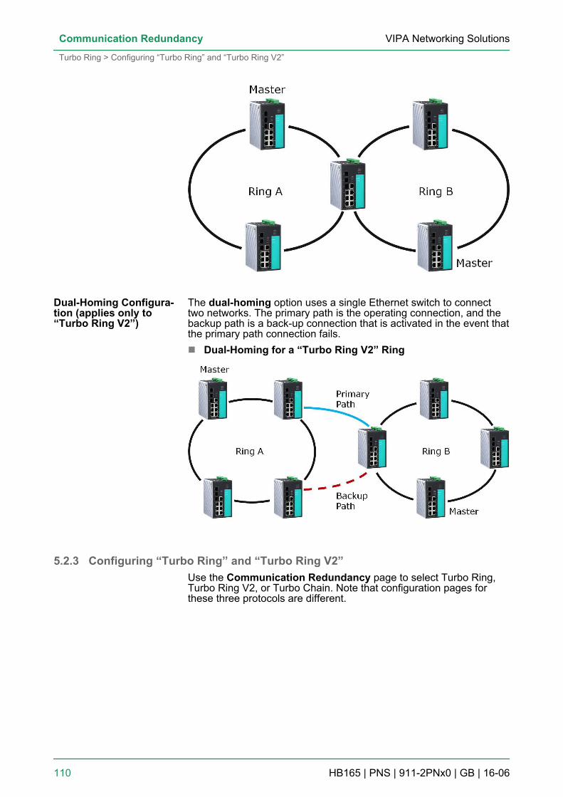
The dual-homing option uses a single Ethernet switch to connecttwo networks. The primary path is the operating connection, and thebackup path is a back-up connection that is activated in the event thatthe primary path connection fails.n Dual-Homing for a “Turbo Ring V2” Ring
5.2.3 Configuring “Turbo Ring” and “Turbo Ring V2”Use the Communication Redundancy page to select Turbo Ring,Turbo Ring V2, or Turbo Chain. Note that configuration pages forthese three protocols are different.
Dual-Homing Configura-tion (applies only to“Turbo Ring V2”)
VIPA Networking SolutionsCommunication Redundancy
Turbo Ring > Configuring “Turbo Ring” and “Turbo Ring V2”
HB165 | PNS | 911-2PNx0 | GB | 16-06 110
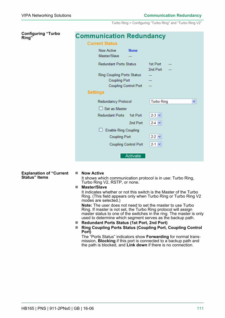
n Now ActiveIt shows which communication protocol is in use: Turbo Ring,Turbo Ring V2, RSTP, or none.
n Master/SlaveIt indicates whether or not this switch is the Master of the TurboRing. (This field appears only when Turbo Ring or Turbo Ring V2modes are selected.)Note: The user does not need to set the master to use TurboRing. If master is not set, the Turbo Ring protocol will assignmaster status to one of the switches in the ring. The master is onlyused to determine which segment serves as the backup path.
n Redundant Ports Status (1st Port, 2nd Port)n Ring Coupling Ports Status (Coupling Port, Coupling Control
Port)The “Ports Status” indicators show Forwarding for normal trans-mission, Blocking if this port is connected to a backup path andthe path is blocked, and Link down if there is no connection.
Configuring “TurboRing”
Explanation of “CurrentStatus” Items
VIPA Networking Solutions Communication Redundancy
Turbo Ring > Configuring “Turbo Ring” and “Turbo Ring V2”
HB165 | PNS | 911-2PNx0 | GB | 16-06 111
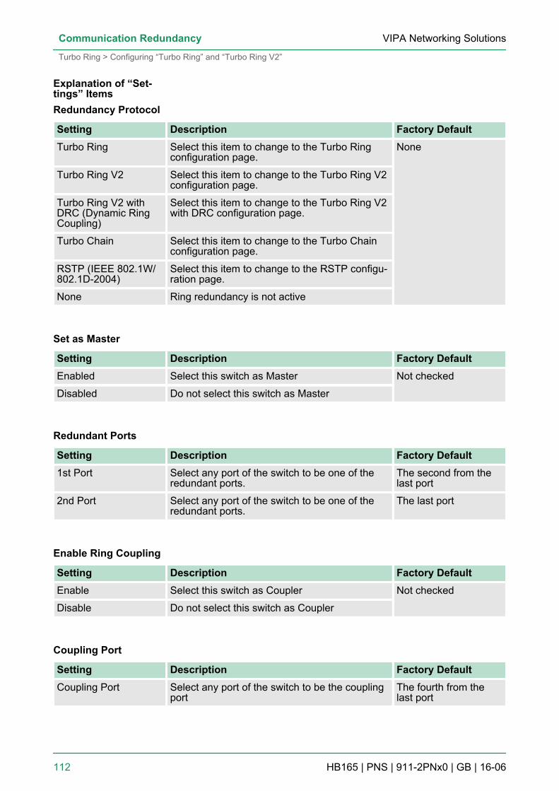
Redundancy Protocol
Setting Description Factory DefaultTurbo Ring Select this item to change to the Turbo Ring
configuration page.None
Turbo Ring V2 Select this item to change to the Turbo Ring V2configuration page.
Turbo Ring V2 withDRC (Dynamic RingCoupling)
Select this item to change to the Turbo Ring V2with DRC configuration page.
Turbo Chain Select this item to change to the Turbo Chainconfiguration page.
RSTP (IEEE 802.1W/802.1D-2004)
Select this item to change to the RSTP configu-ration page.
None Ring redundancy is not active
Set as Master
Setting Description Factory DefaultEnabled Select this switch as Master Not checked
Disabled Do not select this switch as Master
Redundant Ports
Setting Description Factory Default1st Port Select any port of the switch to be one of the
redundant ports.The second from thelast port
2nd Port Select any port of the switch to be one of theredundant ports.
The last port
Enable Ring Coupling
Setting Description Factory DefaultEnable Select this switch as Coupler Not checked
Disable Do not select this switch as Coupler
Coupling Port
Setting Description Factory DefaultCoupling Port Select any port of the switch to be the coupling
portThe fourth from thelast port
Explanation of “Set-tings” Items
VIPA Networking SolutionsCommunication Redundancy
Turbo Ring > Configuring “Turbo Ring” and “Turbo Ring V2”
HB165 | PNS | 911-2PNx0 | GB | 16-06 112
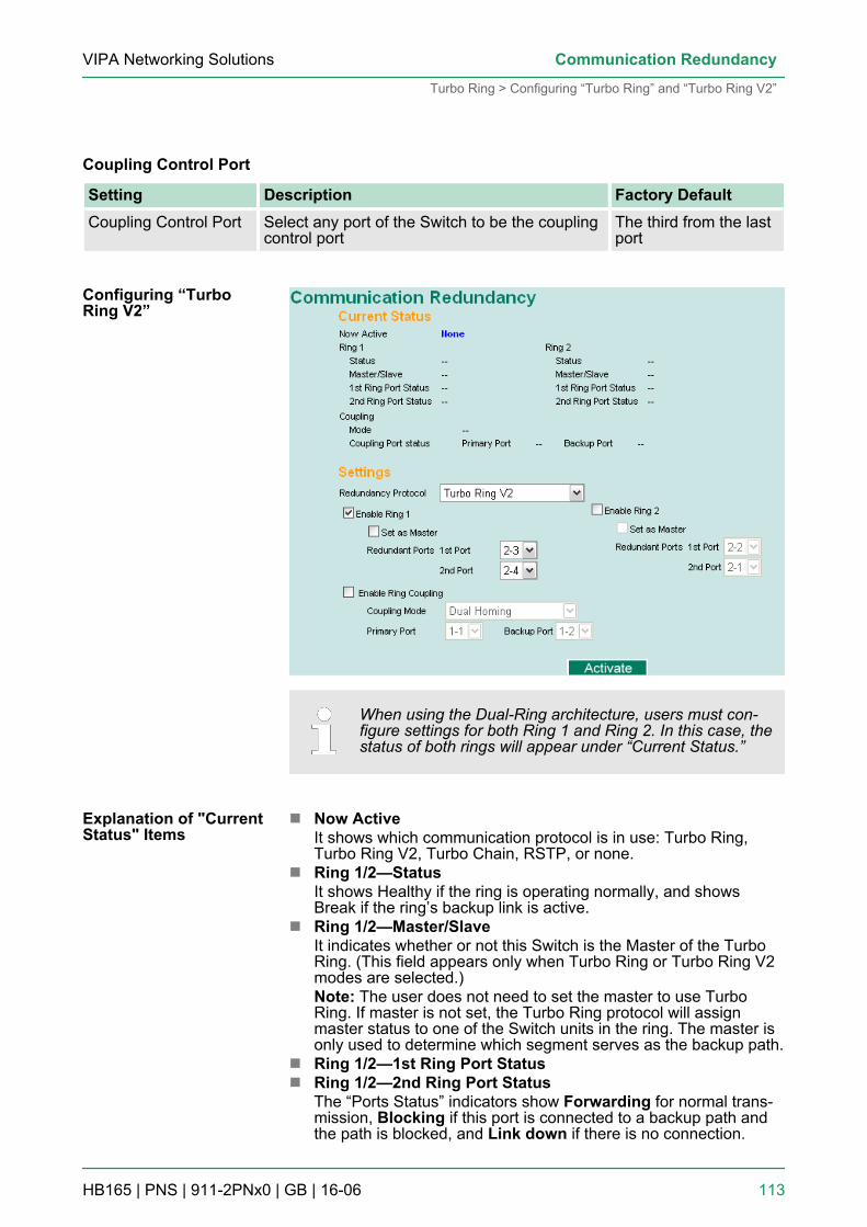
Coupling Control Port
Setting Description Factory DefaultCoupling Control Port Select any port of the Switch to be the coupling
control portThe third from the lastport
When using the Dual-Ring architecture, users must con-figure settings for both Ring 1 and Ring 2. In this case, thestatus of both rings will appear under “Current Status.”
n Now ActiveIt shows which communication protocol is in use: Turbo Ring,Turbo Ring V2, Turbo Chain, RSTP, or none.
n Ring 1/2—StatusIt shows Healthy if the ring is operating normally, and showsBreak if the ring’s backup link is active.
n Ring 1/2—Master/SlaveIt indicates whether or not this Switch is the Master of the TurboRing. (This field appears only when Turbo Ring or Turbo Ring V2modes are selected.)Note: The user does not need to set the master to use TurboRing. If master is not set, the Turbo Ring protocol will assignmaster status to one of the Switch units in the ring. The master isonly used to determine which segment serves as the backup path.
n Ring 1/2—1st Ring Port Statusn Ring 1/2—2nd Ring Port Status
The “Ports Status” indicators show Forwarding for normal trans-mission, Blocking if this port is connected to a backup path andthe path is blocked, and Link down if there is no connection.
Configuring “TurboRing V2”
Explanation of "CurrentStatus" Items
VIPA Networking Solutions Communication Redundancy
Turbo Ring > Configuring “Turbo Ring” and “Turbo Ring V2”
HB165 | PNS | 911-2PNx0 | GB | 16-06 113
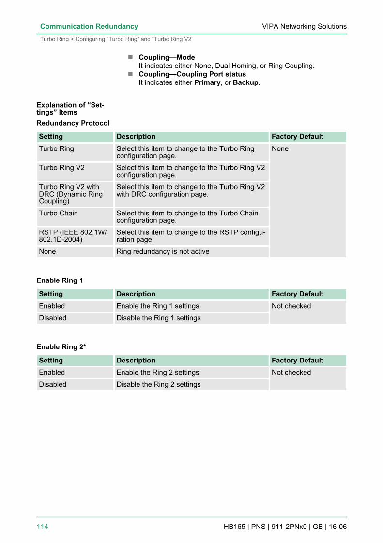
n Coupling—ModeIt indicates either None, Dual Homing, or Ring Coupling.
n Coupling—Coupling Port statusIt indicates either Primary, or Backup.
Redundancy Protocol
Setting Description Factory DefaultTurbo Ring Select this item to change to the Turbo Ring
configuration page.None
Turbo Ring V2 Select this item to change to the Turbo Ring V2configuration page.
Turbo Ring V2 withDRC (Dynamic RingCoupling)
Select this item to change to the Turbo Ring V2with DRC configuration page.
Turbo Chain Select this item to change to the Turbo Chainconfiguration page.
RSTP (IEEE 802.1W/802.1D-2004)
Select this item to change to the RSTP configu-ration page.
None Ring redundancy is not active
Enable Ring 1
Setting Description Factory DefaultEnabled Enable the Ring 1 settings Not checked
Disabled Disable the Ring 1 settings
Enable Ring 2*
Setting Description Factory DefaultEnabled Enable the Ring 2 settings Not checked
Disabled Disable the Ring 2 settings
Explanation of “Set-tings” Items
VIPA Networking SolutionsCommunication Redundancy
Turbo Ring > Configuring “Turbo Ring” and “Turbo Ring V2”
HB165 | PNS | 911-2PNx0 | GB | 16-06 114
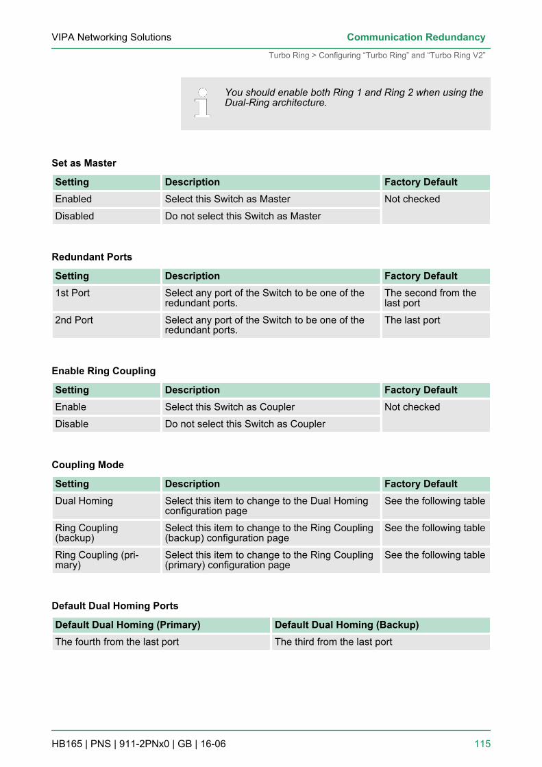
You should enable both Ring 1 and Ring 2 when using theDual-Ring architecture.
Set as Master
Setting Description Factory DefaultEnabled Select this Switch as Master Not checked
Disabled Do not select this Switch as Master
Redundant Ports
Setting Description Factory Default1st Port Select any port of the Switch to be one of the
redundant ports.The second from thelast port
2nd Port Select any port of the Switch to be one of theredundant ports.
The last port
Enable Ring Coupling
Setting Description Factory DefaultEnable Select this Switch as Coupler Not checked
Disable Do not select this Switch as Coupler
Coupling Mode
Setting Description Factory DefaultDual Homing Select this item to change to the Dual Homing
configuration pageSee the following table
Ring Coupling(backup)
Select this item to change to the Ring Coupling(backup) configuration page
See the following table
Ring Coupling (pri-mary)
Select this item to change to the Ring Coupling(primary) configuration page
See the following table
Default Dual Homing Ports
Default Dual Homing (Primary) Default Dual Homing (Backup)The fourth from the last port The third from the last port
VIPA Networking Solutions Communication Redundancy
Turbo Ring > Configuring “Turbo Ring” and “Turbo Ring V2”
HB165 | PNS | 911-2PNx0 | GB | 16-06 115
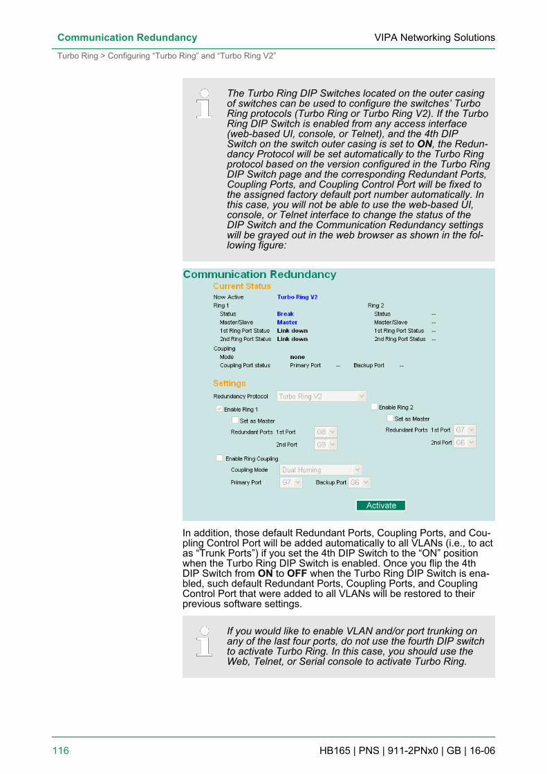
The Turbo Ring DIP Switches located on the outer casingof switches can be used to configure the switches’ TurboRing protocols (Turbo Ring or Turbo Ring V2). If the TurboRing DIP Switch is enabled from any access interface(web-based UI, console, or Telnet), and the 4th DIPSwitch on the switch outer casing is set to ON, the Redun-dancy Protocol will be set automatically to the Turbo Ringprotocol based on the version configured in the Turbo RingDIP Switch page and the corresponding Redundant Ports,Coupling Ports, and Coupling Control Port will be fixed tothe assigned factory default port number automatically. Inthis case, you will not be able to use the web-based UI,console, or Telnet interface to change the status of theDIP Switch and the Communication Redundancy settingswill be grayed out in the web browser as shown in the fol-lowing figure:
In addition, those default Redundant Ports, Coupling Ports, and Cou-pling Control Port will be added automatically to all VLANs (i.e., to actas “Trunk Ports”) if you set the 4th DIP Switch to the “ON” positionwhen the Turbo Ring DIP Switch is enabled. Once you flip the 4thDIP Switch from ON to OFF when the Turbo Ring DIP Switch is ena-bled, such default Redundant Ports, Coupling Ports, and CouplingControl Port that were added to all VLANs will be restored to theirprevious software settings.
If you would like to enable VLAN and/or port trunking onany of the last four ports, do not use the fourth DIP switchto activate Turbo Ring. In this case, you should use theWeb, Telnet, or Serial console to activate Turbo Ring.
VIPA Networking SolutionsCommunication Redundancy
Turbo Ring > Configuring “Turbo Ring” and “Turbo Ring V2”
HB165 | PNS | 911-2PNx0 | GB | 16-06 116
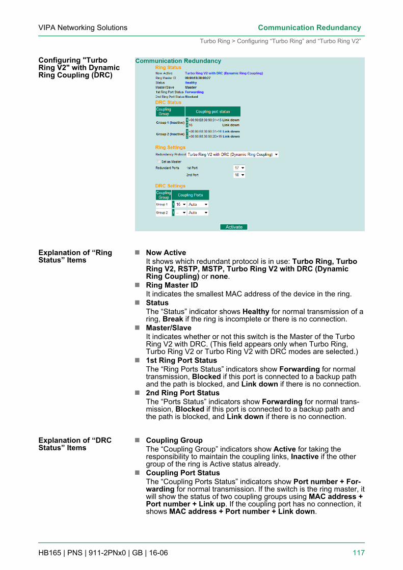
n Now ActiveIt shows which redundant protocol is in use: Turbo Ring, TurboRing V2, RSTP, MSTP, Turbo Ring V2 with DRC (DynamicRing Coupling) or none.
n Ring Master IDIt indicates the smallest MAC address of the device in the ring.
n StatusThe “Status” indicator shows Healthy for normal transmission of aring, Break if the ring is incomplete or there is no connection.
n Master/SlaveIt indicates whether or not this switch is the Master of the TurboRing V2 with DRC. (This field appears only when Turbo Ring,Turbo Ring V2 or Turbo Ring V2 with DRC modes are selected.)
n 1st Ring Port StatusThe “Ring Ports Status” indicators show Forwarding for normaltransmission, Blocked if this port is connected to a backup pathand the path is blocked, and Link down if there is no connection.
n 2nd Ring Port StatusThe “Ports Status” indicators show Forwarding for normal trans-mission, Blocked if this port is connected to a backup path andthe path is blocked, and Link down if there is no connection.
n Coupling GroupThe “Coupling Group” indicators show Active for taking theresponsibility to maintain the coupling links, Inactive if the othergroup of the ring is Active status already.
n Coupling Port StatusThe “Coupling Ports Status” indicators show Port number + For-warding for normal transmission. If the switch is the ring master, itwill show the status of two coupling groups using MAC address +Port number + Link up. If the coupling port has no connection, itshows MAC address + Port number + Link down.
Configuring "TurboRing V2" with DynamicRing Coupling (DRC)
Explanation of “RingStatus” Items
Explanation of “DRCStatus” Items
VIPA Networking Solutions Communication Redundancy
Turbo Ring > Configuring “Turbo Ring” and “Turbo Ring V2”
HB165 | PNS | 911-2PNx0 | GB | 16-06 117
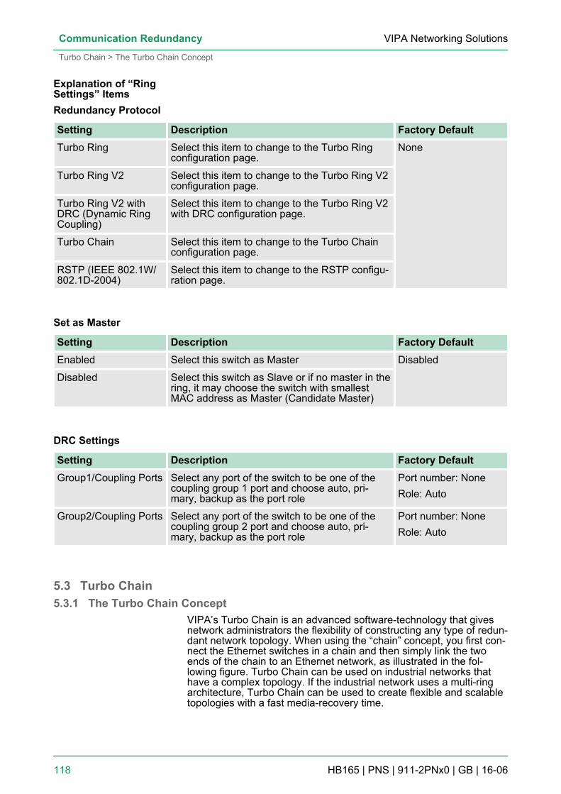
Redundancy Protocol
Setting Description Factory DefaultTurbo Ring Select this item to change to the Turbo Ring
configuration page.None
Turbo Ring V2 Select this item to change to the Turbo Ring V2configuration page.
Turbo Ring V2 withDRC (Dynamic RingCoupling)
Select this item to change to the Turbo Ring V2with DRC configuration page.
Turbo Chain Select this item to change to the Turbo Chainconfiguration page.
RSTP (IEEE 802.1W/802.1D-2004)
Select this item to change to the RSTP configu-ration page.
Set as Master
Setting Description Factory DefaultEnabled Select this switch as Master Disabled
Disabled Select this switch as Slave or if no master in thering, it may choose the switch with smallestMAC address as Master (Candidate Master)
DRC Settings
Setting Description Factory DefaultGroup1/Coupling Ports Select any port of the switch to be one of the
coupling group 1 port and choose auto, pri-mary, backup as the port role
Port number: NoneRole: Auto
Group2/Coupling Ports Select any port of the switch to be one of thecoupling group 2 port and choose auto, pri-mary, backup as the port role
Port number: NoneRole: Auto
5.3 Turbo Chain5.3.1 The Turbo Chain Concept
VIPA’s Turbo Chain is an advanced software-technology that givesnetwork administrators the flexibility of constructing any type of redun-dant network topology. When using the “chain” concept, you first con-nect the Ethernet switches in a chain and then simply link the twoends of the chain to an Ethernet network, as illustrated in the fol-lowing figure. Turbo Chain can be used on industrial networks thathave a complex topology. If the industrial network uses a multi-ringarchitecture, Turbo Chain can be used to create flexible and scalabletopologies with a fast media-recovery time.
Explanation of “RingSettings” Items
VIPA Networking SolutionsCommunication Redundancy
Turbo Chain > The Turbo Chain Concept
HB165 | PNS | 911-2PNx0 | GB | 16-06 118
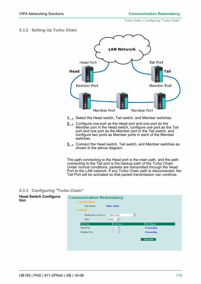
5.3.2 Setting Up Turbo Chain
1. Select the Head switch, Tail switch, and Member switches.2. Configure one port as the Head port and one port as the
Member port in the Head switch, configure one port as the Tailport and one port as the Member port in the Tail switch, andconfigure two ports as Member ports in each of the Memberswitches.
3. Connect the Head switch, Tail switch, and Member switches asshown in the above diagram.
The path connecting to the Head port is the main path, and the pathconnecting to the Tail port is the backup path of the Turbo Chain.Under normal conditions, packets are transmitted through the HeadPort to the LAN network. If any Turbo Chain path is disconnected, theTail Port will be activated so that packet transmission can continue.
5.3.3 Configuring "Turbo Chain"Head Switch Configura-tion
VIPA Networking Solutions Communication Redundancy
Turbo Chain > Configuring "Turbo Chain"
HB165 | PNS | 911-2PNx0 | GB | 16-06 119
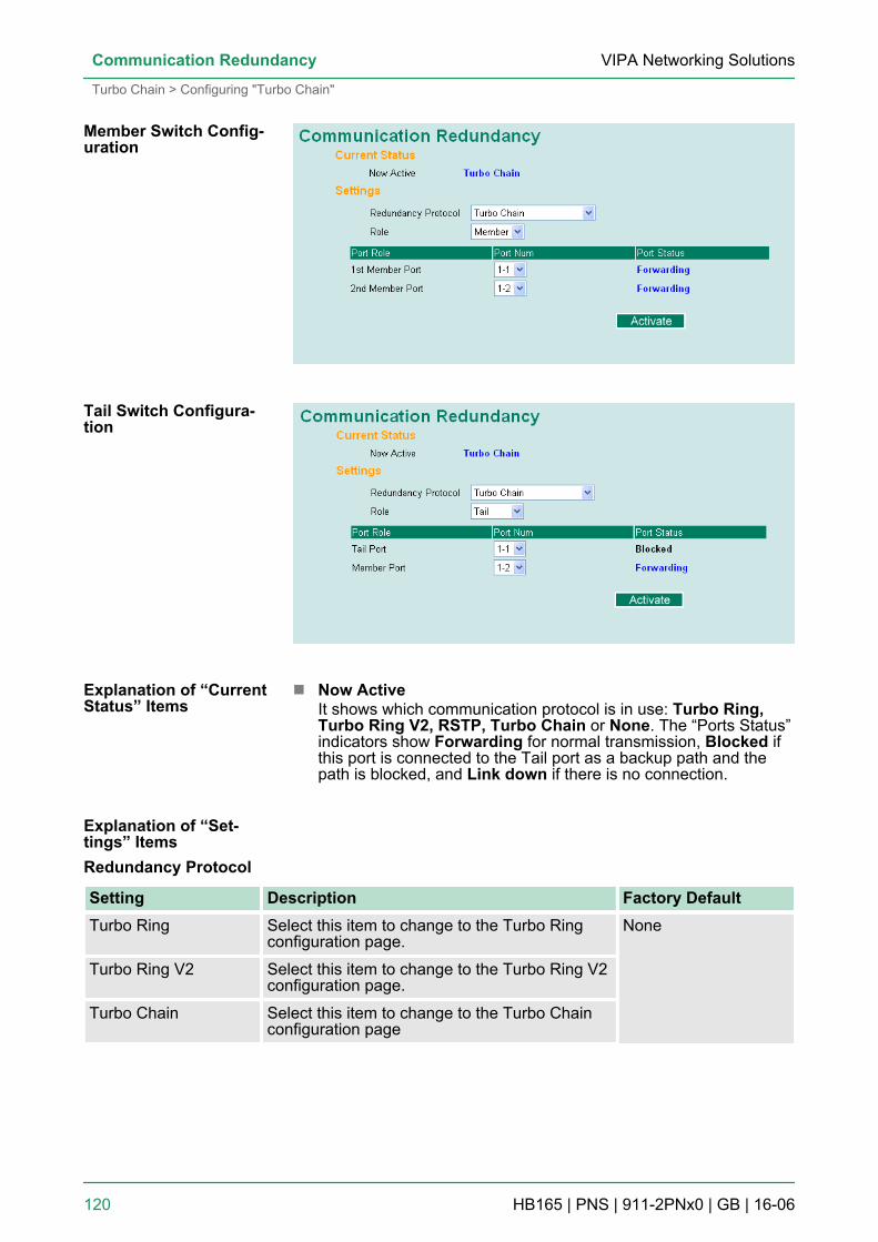
n Now ActiveIt shows which communication protocol is in use: Turbo Ring,Turbo Ring V2, RSTP, Turbo Chain or None. The “Ports Status”indicators show Forwarding for normal transmission, Blocked ifthis port is connected to the Tail port as a backup path and thepath is blocked, and Link down if there is no connection.
Redundancy Protocol
Setting Description Factory DefaultTurbo Ring Select this item to change to the Turbo Ring
configuration page.None
Turbo Ring V2 Select this item to change to the Turbo Ring V2configuration page.
Turbo Chain Select this item to change to the Turbo Chainconfiguration page
Member Switch Config-uration
Tail Switch Configura-tion
Explanation of “CurrentStatus” Items
Explanation of “Set-tings” Items
VIPA Networking SolutionsCommunication Redundancy
Turbo Chain > Configuring "Turbo Chain"
HB165 | PNS | 911-2PNx0 | GB | 16-06 120
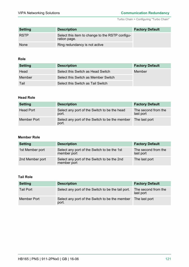
Setting Description Factory DefaultRSTP Select this item to change to the RSTP configu-
ration page.
None Ring redundancy is not active
Role
Setting Description Factory DefaultHead Select this Switch as Head Switch Member
Member Select this Switch as Member Switch
Tail Select this Switch as Tail Switch
Head Role
Setting Description Factory DefaultHead Port Select any port of the Switch to be the head
port.The second from thelast port
Member Port Select any port of the Switch to be the memberport.
The last port
Member Role
Setting Description Factory Default1st Member port Select any port of the Switch to be the 1st
member portThe second from thelast port
2nd Member port Select any port of the Switch to be the 2ndmember port
The last port
Tail Role
Setting Description Factory DefaultTail Port Select any port of the Switch to be the tail port. The second from the
last port
Member Port Select any port of the Switch to be the memberport.
The last port
VIPA Networking Solutions Communication Redundancy
Turbo Chain > Configuring "Turbo Chain"
HB165 | PNS | 911-2PNx0 | GB | 16-06 121
5.4 STP/RSTP/MSTP5.4.1 The STP/RSTP/MSTP Concept
Spanning Tree Protocol (STP) was designed to help reduce link fail-ures on a network, and provide an automatic means of avoidingloops. This is particularly important for networks that have a compli-cated architecture, since unintended loops in the network can causebroadcast storms. VIPA switches’ STP feature is disabled by default.To be completely effective, you must enable RSTP/STP on everyVIPA switch connected to your network.Rapid Spanning Tree Protocol (RSTP) implements the Spanning TreeAlgorithm and Protocol defined by IEEE 802.1D-2004. RSTP providesthe following benefits:n The topology of a bridged network will be determined much more
quickly compared to STP.n RSTP is backward compatible with STP, making it relatively easy
to deploy. For example:– Defaults to sending 802.1D style BPDUs if packets with this
format are received.– STP (802.1D) and RSTP (802.1w) can operate on different
ports of the same switch, which is particularly helpful whenswitch ports connect to older equipment such as legacyswitches.
You get essentially the same functionality with RSTP and STP. Tosee how the two systems differ, see the Differences between STPand RSTP section in this chapter.
The STP protocol is part of the IEEE Std 802.1D, 2004Edition bridge specification. The following explanationuses “bridge” instead of “switch.”
STP (802.1D) is a bridge-based system that is used to implementparallel paths for network traffic. STP uses a loop-detection processto:n Locate and then disable less efficient paths (i.e., paths that have a
lower bandwidth).n Enable one of the less efficient paths if a more efficient path fails.The figure below shows a network made up of three LANs separatedby three bridges. Each segment uses at most two paths to communi-cate with the other segments. Since this configuration can give rise toloops, the network will overload if STP is NOT enabled.
What is STP?
VIPA Networking SolutionsCommunication Redundancy
STP/RSTP/MSTP > The STP/RSTP/MSTP Concept
HB165 | PNS | 911-2PNx0 | GB | 16-06 122
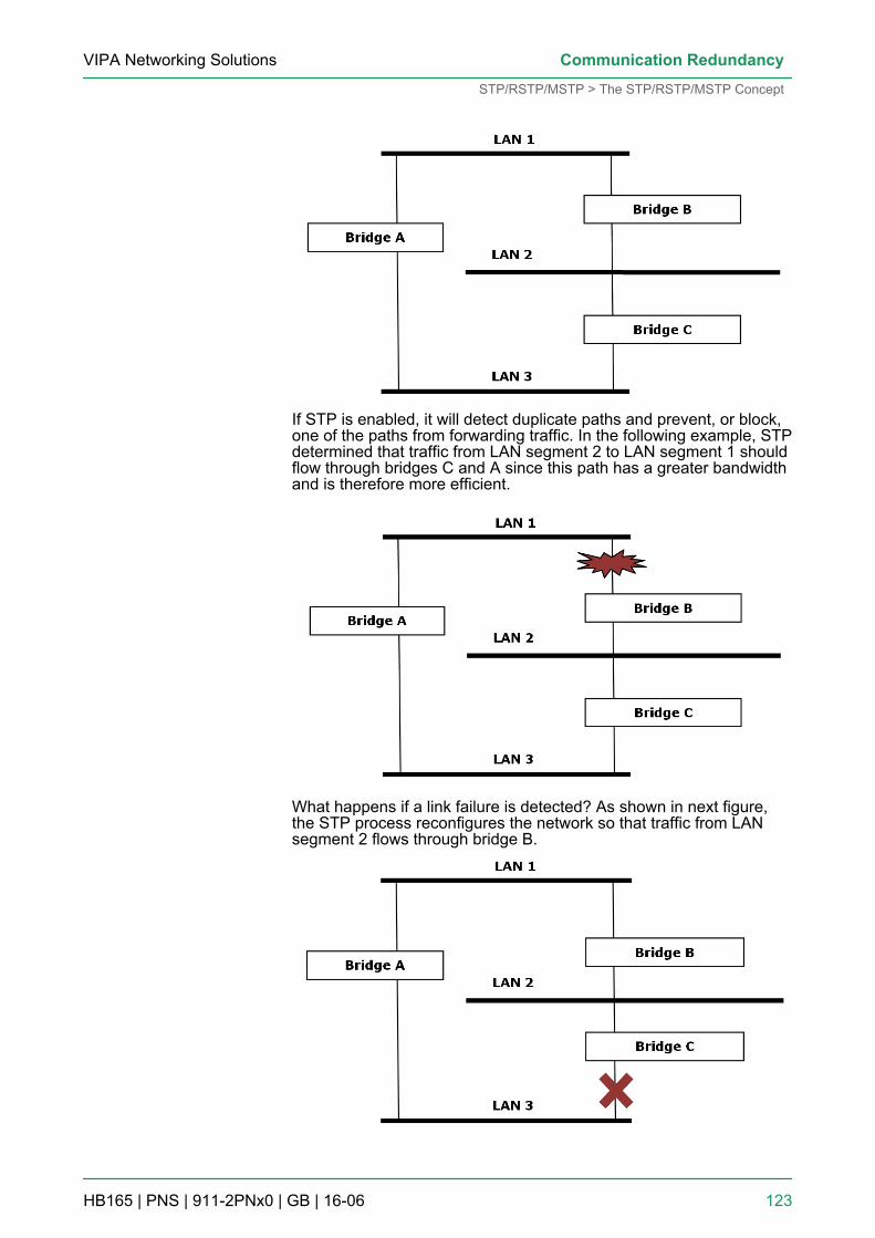
If STP is enabled, it will detect duplicate paths and prevent, or block,one of the paths from forwarding traffic. In the following example, STPdetermined that traffic from LAN segment 2 to LAN segment 1 shouldflow through bridges C and A since this path has a greater bandwidthand is therefore more efficient.
What happens if a link failure is detected? As shown in next figure,the STP process reconfigures the network so that traffic from LANsegment 2 flows through bridge B.
VIPA Networking Solutions Communication Redundancy
STP/RSTP/MSTP > The STP/RSTP/MSTP Concept
HB165 | PNS | 911-2PNx0 | GB | 16-06 123
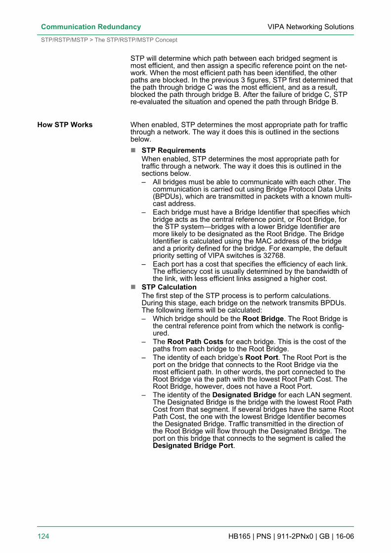
STP will determine which path between each bridged segment ismost efficient, and then assign a specific reference point on the net-work. When the most efficient path has been identified, the otherpaths are blocked. In the previous 3 figures, STP first determined thatthe path through bridge C was the most efficient, and as a result,blocked the path through bridge B. After the failure of bridge C, STPre-evaluated the situation and opened the path through Bridge B.
When enabled, STP determines the most appropriate path for trafficthrough a network. The way it does this is outlined in the sectionsbelow.n STP Requirements
When enabled, STP determines the most appropriate path fortraffic through a network. The way it does this is outlined in thesections below.– All bridges must be able to communicate with each other. The
communication is carried out using Bridge Protocol Data Units(BPDUs), which are transmitted in packets with a known multi-cast address.
– Each bridge must have a Bridge Identifier that specifies whichbridge acts as the central reference point, or Root Bridge, forthe STP system—bridges with a lower Bridge Identifier aremore likely to be designated as the Root Bridge. The BridgeIdentifier is calculated using the MAC address of the bridgeand a priority defined for the bridge. For example, the defaultpriority setting of VIPA switches is 32768.
– Each port has a cost that specifies the efficiency of each link.The efficiency cost is usually determined by the bandwidth ofthe link, with less efficient links assigned a higher cost.
n STP CalculationThe first step of the STP process is to perform calculations.During this stage, each bridge on the network transmits BPDUs.The following items will be calculated:– Which bridge should be the Root Bridge. The Root Bridge is
the central reference point from which the network is config-ured.
– The Root Path Costs for each bridge. This is the cost of thepaths from each bridge to the Root Bridge.
– The identity of each bridge’s Root Port. The Root Port is theport on the bridge that connects to the Root Bridge via themost efficient path. In other words, the port connected to theRoot Bridge via the path with the lowest Root Path Cost. TheRoot Bridge, however, does not have a Root Port.
– The identity of the Designated Bridge for each LAN segment.The Designated Bridge is the bridge with the lowest Root PathCost from that segment. If several bridges have the same RootPath Cost, the one with the lowest Bridge Identifier becomesthe Designated Bridge. Traffic transmitted in the direction ofthe Root Bridge will flow through the Designated Bridge. Theport on this bridge that connects to the segment is called theDesignated Bridge Port.
How STP Works
VIPA Networking SolutionsCommunication Redundancy
STP/RSTP/MSTP > The STP/RSTP/MSTP Concept
HB165 | PNS | 911-2PNx0 | GB | 16-06 124
n STP ConfigurationAfter all of the bridges on the network agree on the identity of theRoot Bridge, and all other relevant parameters have been estab-lished, each bridge is configured to forward traffic only between itsRoot Port and the Designated Bridge Ports for the respective net-work segments. All other ports are blocked, which means thatthey will not be allowed to receive or forward traffic.
n STP ReconfigurationOnce the network topology has stabilized, each bridge listens forHello BPDUs transmitted from the Root Bridge at regular intervals.If a bridge does not receive a Hello BPDU after a certain interval(the Max Age time), the bridge assumes that the Root Bridge, or alink between itself and the Root Bridge, has ceased to function.This will trigger the bridge to reconfigure the network to accountfor the change. If you have configured an SNMP trap destination,when the topology of your network changes, the first bridge todetect the change will send out an SNMP trap.
RSTP is similar to STP, but includes additional information in theBPDUs that allow each bridge to confirm that it has taken action toprevent loops from forming when it decides to enable a link to aneighboring bridge. Adjacent bridges connected via point-to-pointlinks will be able to enable a link without waiting to ensure that allother bridges in the network have had time to react to the change.The main benefit of RSTP is that the configuration decision is madelocally rather than network-wide, allowing RSTP to carry out auto-matic configuration and restore a link faster than STP. STP andRSTP spanning tree protocols operate without regard to a network’sVLAN configuration, and maintain one common spanning treethroughout a bridged network. Thus, these protocols map one loop-free, logical topology on a given physical topology. MSTP usesVLANs to create multiple spanning trees in a network, which signifi-cantly improves network resource utilization while maintaining a loop-free environment.
5.4.2 STP ExampleThe LAN shown in the following figure has three segments, with adja-cent segments connected using two possible links. The various STPfactors, such as Cost, Root Port, Designated Bridge Port, andBlocked Port are shown in the figure.
Differences betweenSTP, RSTP, and MSTP
VIPA Networking Solutions Communication Redundancy
STP/RSTP/MSTP > STP Example
HB165 | PNS | 911-2PNx0 | GB | 16-06 125
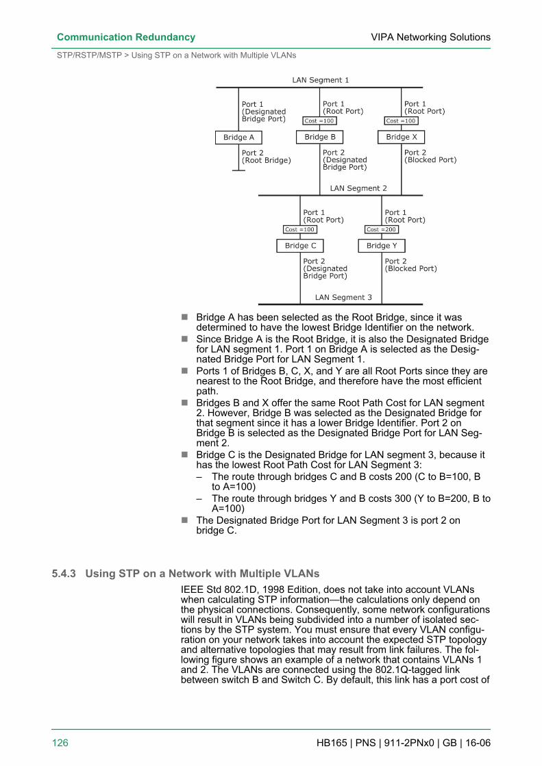
n Bridge A has been selected as the Root Bridge, since it wasdetermined to have the lowest Bridge Identifier on the network.
n Since Bridge A is the Root Bridge, it is also the Designated Bridgefor LAN segment 1. Port 1 on Bridge A is selected as the Desig-nated Bridge Port for LAN Segment 1.
n Ports 1 of Bridges B, C, X, and Y are all Root Ports since they arenearest to the Root Bridge, and therefore have the most efficientpath.
n Bridges B and X offer the same Root Path Cost for LAN segment2. However, Bridge B was selected as the Designated Bridge forthat segment since it has a lower Bridge Identifier. Port 2 onBridge B is selected as the Designated Bridge Port for LAN Seg-ment 2.
n Bridge C is the Designated Bridge for LAN segment 3, because ithas the lowest Root Path Cost for LAN Segment 3:– The route through bridges C and B costs 200 (C to B=100, B
to A=100)– The route through bridges Y and B costs 300 (Y to B=200, B to
A=100)n The Designated Bridge Port for LAN Segment 3 is port 2 on
bridge C.
5.4.3 Using STP on a Network with Multiple VLANsIEEE Std 802.1D, 1998 Edition, does not take into account VLANswhen calculating STP information—the calculations only depend onthe physical connections. Consequently, some network configurationswill result in VLANs being subdivided into a number of isolated sec-tions by the STP system. You must ensure that every VLAN configu-ration on your network takes into account the expected STP topologyand alternative topologies that may result from link failures. The fol-lowing figure shows an example of a network that contains VLANs 1and 2. The VLANs are connected using the 802.1Q-tagged linkbetween switch B and Switch C. By default, this link has a port cost of
VIPA Networking SolutionsCommunication Redundancy
STP/RSTP/MSTP > Using STP on a Network with Multiple VLANs
HB165 | PNS | 911-2PNx0 | GB | 16-06 126
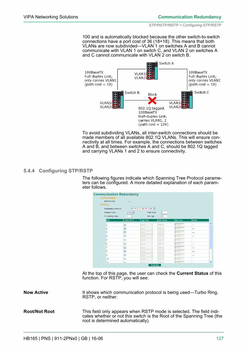
100 and is automatically blocked because the other switch-to-switchconnections have a port cost of 36 (18+18). This means that bothVLANs are now subdivided—VLAN 1 on switches A and B cannotcommunicate with VLAN 1 on switch C, and VLAN 2 on switches Aand C cannot communicate with VLAN 2 on switch B.
To avoid subdividing VLANs, all inter-switch connections should bemade members of all available 802.1Q VLANs. This will ensure con-nectivity at all times. For example, the connections between switchesA and B, and between switches A and C, should be 802.1Q taggedand carrying VLANs 1 and 2 to ensure connectivity.
5.4.4 Configuring STP/RSTPThe following figures indicate which Spanning Tree Protocol parame-ters can be configured. A more detailed explanation of each param-eter follows.
At the top of this page, the user can check the Current Status of thisfunction. For RSTP, you will see:
It shows which communication protocol is being used—Turbo Ring,RSTP, or neither.
This field only appears when RSTP mode is selected. The field indi-cates whether or not this switch is the Root of the Spanning Tree (theroot is determined automatically).
Now Active
Root/Not Root
VIPA Networking Solutions Communication Redundancy
STP/RSTP/MSTP > Configuring STP/RSTP
HB165 | PNS | 911-2PNx0 | GB | 16-06 127
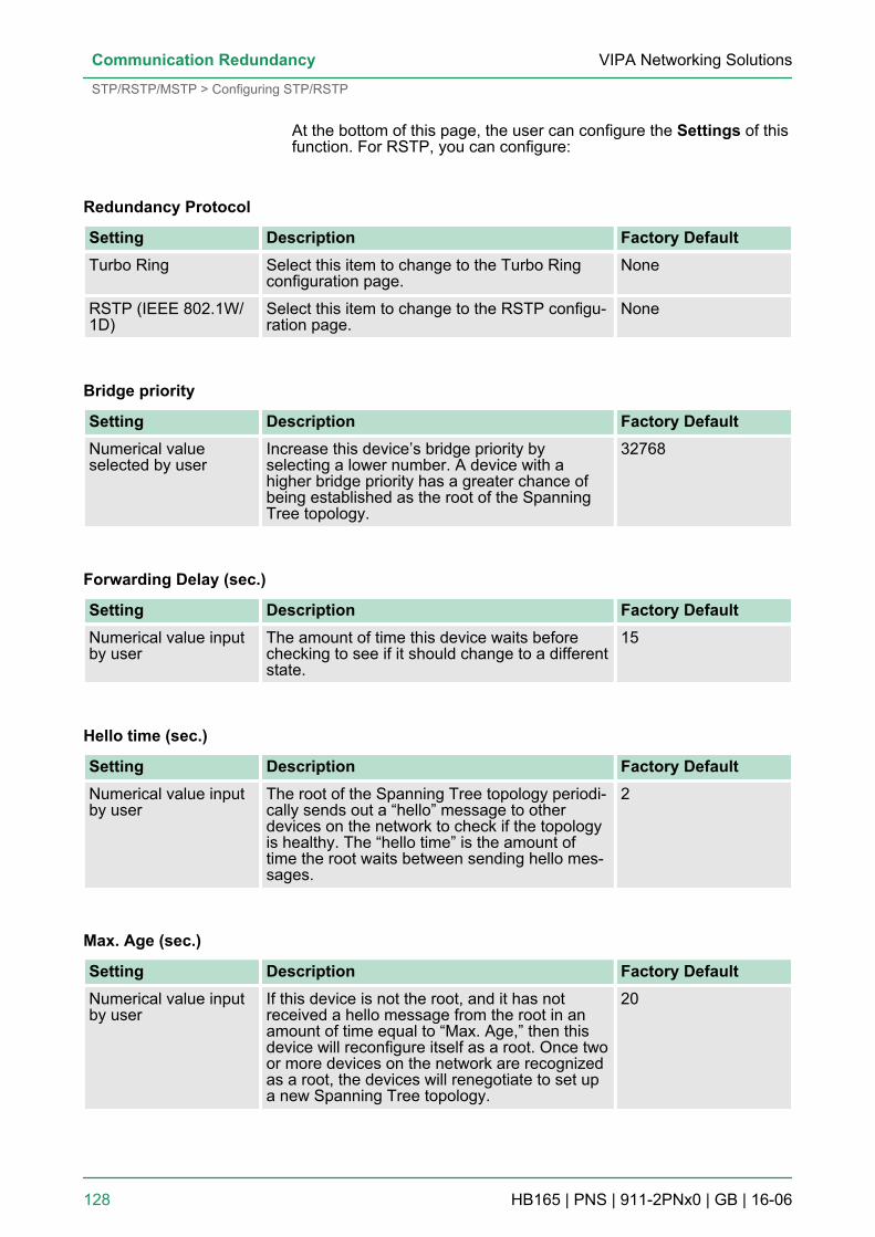
At the bottom of this page, the user can configure the Settings of thisfunction. For RSTP, you can configure:
Redundancy Protocol
Setting Description Factory DefaultTurbo Ring Select this item to change to the Turbo Ring
configuration page.None
RSTP (IEEE 802.1W/1D)
Select this item to change to the RSTP configu-ration page.
None
Bridge priority
Setting Description Factory DefaultNumerical valueselected by user
Increase this device’s bridge priority byselecting a lower number. A device with ahigher bridge priority has a greater chance ofbeing established as the root of the SpanningTree topology.
32768
Forwarding Delay (sec.)
Setting Description Factory DefaultNumerical value inputby user
The amount of time this device waits beforechecking to see if it should change to a differentstate.
15
Hello time (sec.)
Setting Description Factory DefaultNumerical value inputby user
The root of the Spanning Tree topology periodi-cally sends out a “hello” message to otherdevices on the network to check if the topologyis healthy. The “hello time” is the amount oftime the root waits between sending hello mes-sages.
2
Max. Age (sec.)
Setting Description Factory DefaultNumerical value inputby user
If this device is not the root, and it has notreceived a hello message from the root in anamount of time equal to “Max. Age,” then thisdevice will reconfigure itself as a root. Once twoor more devices on the network are recognizedas a root, the devices will renegotiate to set upa new Spanning Tree topology.
20
VIPA Networking SolutionsCommunication Redundancy
STP/RSTP/MSTP > Configuring STP/RSTP
HB165 | PNS | 911-2PNx0 | GB | 16-06 128
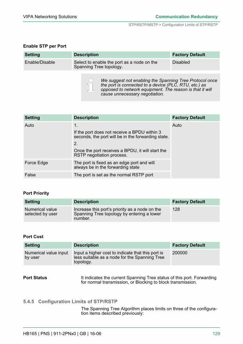
Enable STP per Port
Setting Description Factory DefaultEnable/Disable Select to enable the port as a node on the
Spanning Tree topology.Disabled
We suggest not enabling the Spanning Tree Protocol oncethe port is connected to a device (PLC, RTU, etc.) asopposed to network equipment. The reason is that it willcause unnecessary negotiation.
Setting Description Factory DefaultAuto 1.
If the port does not receive a BPDU within 3seconds, the port will be in the forwarding state.2.Once the port receives a BPDU, it will start theRSTP negotiation process.
Auto
Force Edge The port is fixed as an edge port and willalways be in the forwarding state
False The port is set as the normal RSTP port
Port Priority
Setting Description Factory DefaultNumerical valueselected by user
Increase this port’s priority as a node on theSpanning Tree topology by entering a lowernumber.
128
Port Cost
Setting Description Factory DefaultNumerical value inputby user
Input a higher cost to indicate that this port isless suitable as a node for the Spanning Treetopology.
200000
It indicates the current Spanning Tree status of this port. Forwardingfor normal transmission, or Blocking to block transmission.
5.4.5 Configuration Limits of STP/RSTPThe Spanning Tree Algorithm places limits on three of the configura-tion items described previously:
Port Status
VIPA Networking Solutions Communication Redundancy
STP/RSTP/MSTP > Configuration Limits of STP/RSTP
HB165 | PNS | 911-2PNx0 | GB | 16-06 129
[Eq. 1]: 1 sec ≦ Hello Time ≦ 10 sec[Eq. 2]: 6 sec ≦ Max. Age ≦ 40 sec[Eq. 3]: 4 sec ≦ Forwarding Delay ≦ 30 secThese three variables are further restricted by the following twoinequalities:[Eq. 4]: 2 x (Hello Time + 1 sec) ≦ Max. Age ≦ 2 x (Forwarding Delay– 1 sec)For example, settingHello Time = 5 sec, Max. Age = 20 sec, and Forwarding Delay = 4sec does not violate Eqs. 1 through 3, but does violate Eq. 4, since inthis case, 2 x (Hello Time + 1 sec) = 12 sec, and 2 x (ForwardingDelay – 1 sec) = 6 sec.You can remedy the situation in many ways. One solution is simply toincrease the Forwarding Delay value to at least 11 sec.Perform the following steps to avoid guessing:1. Assign a value to Hello Time and then calculate the left most
part of Eq. 4 to get the lower limit of Max. Age.2. Assign a value to Forwarding Delay and then calculate the right
most part of Eq. 4 to get the upper limit for Max. Age.3. Assign a value to Forwarding Delay that satisfies the conditions.
VIPA Networking SolutionsCommunication Redundancy
STP/RSTP/MSTP > Configuration Limits of STP/RSTP
HB165 | PNS | 911-2PNx0 | GB | 16-06 130
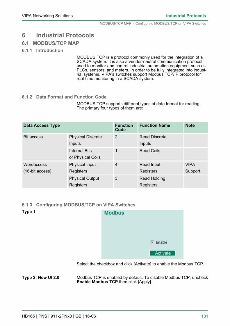
6 Industrial Protocols6.1 MODBUS/TCP MAP6.1.1 Introduction
MODBUS TCP is a protocol commonly used for the integration of aSCADA system. It is also a vendor-neutral communication protocolused to monitor and control industrial automation equipment such asPLCs, sensors, and meters. In order to be fully integrated into indust-rial systems, VIPA’s switches support Modbus TCP/IP protocol forreal-time monitoring in a SCADA system.
6.1.2 Data Format and Function CodeMODBUS TCP supports different types of data format for reading.The primary four types of them are:
Data Access Type FunctionCode
Function Name Note
Bit access Physical DiscreteInputs
2 Read DiscreteInputs
Internal Bitsor Physical Coils
1 Read Coils
Wordaccess(16-bit access)
Physical InputRegisters
4 Read InputRegisters
VIPASupport
Physical OutputRegisters
3 Read HoldingRegisters
6.1.3 Configuring MODBUS/TCP on VIPA Switches
Select the checkbox and click [Activate] to enable the Modbus TCP.
Modbus TCP is enabled by default. To disable Modbus TCP, uncheckEnable Modbus TCP then click [Apply].
Type 1
Type 2: New UI 2.0
VIPA Networking Solutions Industrial Protocols
MODBUS/TCP MAP > Configuring MODBUS/TCP on VIPA Switches
HB165 | PNS | 911-2PNx0 | GB | 16-06 131
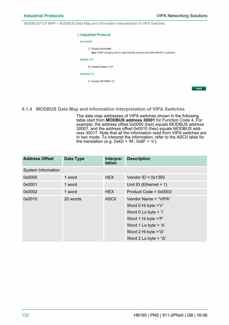
6.1.4 MODBUS Data Map and Information Interpretation of VIPA SwitchesThe data map addresses of VIPA switches shown in the followingtable start from MODBUS address 30001 for Function Code 4. Forexample, the address offset 0x0000 (hex) equals MODBUS address30001, and the address offset 0x0010 (hex) equals MODBUS add-ress 30017. Note that all the information read from VIPA switches arein hex mode. To interpret the information, refer to the ASCII table forthe translation (e.g. 0x4D = ‘M’, 0x6F = ‘o’).
Address Offset Data Type Interpre-tation
Description
System Information
0x0000 1 word HEX Vendor ID = 0x1393
0x0001 1 word Unit ID (Ethernet = 1)
0x0002 1 word HEX Product Code = 0x0003
0x0010 20 words ASCII Vendor Name = “VIPA”Word 0 Hi byte =‘V’Word 0 Lo byte = ‘I’Word 1 Hi byte =‘P’Word 1 Lo byte = ‘A’Word 2 Hi byte =‘\0’Word 2 Lo byte = ‘\0’
VIPA Networking SolutionsIndustrial Protocols
MODBUS/TCP MAP > MODBUS Data Map and Information Interpretation of VIPA Switches
HB165 | PNS | 911-2PNx0 | GB | 16-06 132
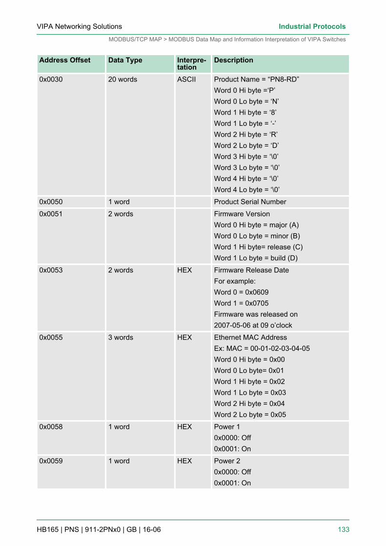
Address Offset Data Type Interpre-tation
Description
0x0030 20 words ASCII Product Name = “PN8-RD”Word 0 Hi byte =‘P’Word 0 Lo byte = ‘N’Word 1 Hi byte = ‘8’Word 1 Lo byte = ‘-’Word 2 Hi byte = ‘R’Word 2 Lo byte = ‘D’Word 3 Hi byte = ‘\0’Word 3 Lo byte = ‘\0’Word 4 Hi byte = ‘\0’Word 4 Lo byte = ‘\0’
0x0050 1 word Product Serial Number
0x0051 2 words Firmware VersionWord 0 Hi byte = major (A)Word 0 Lo byte = minor (B)Word 1 Hi byte= release (C)Word 1 Lo byte = build (D)
0x0053 2 words HEX Firmware Release DateFor example:Word 0 = 0x0609Word 1 = 0x0705Firmware was released on2007-05-06 at 09 o’clock
0x0055 3 words HEX Ethernet MAC AddressEx: MAC = 00-01-02-03-04-05Word 0 Hi byte = 0x00Word 0 Lo byte= 0x01Word 1 Hi byte = 0x02Word 1 Lo byte = 0x03Word 2 Hi byte = 0x04Word 2 Lo byte = 0x05
0x0058 1 word HEX Power 10x0000: Off0x0001: On
0x0059 1 word HEX Power 20x0000: Off0x0001: On
VIPA Networking Solutions Industrial Protocols
MODBUS/TCP MAP > MODBUS Data Map and Information Interpretation of VIPA Switches
HB165 | PNS | 911-2PNx0 | GB | 16-06 133
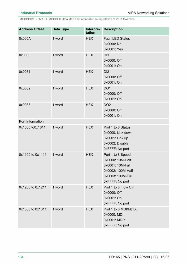
Address Offset Data Type Interpre-tation
Description
0x005A 1 word HEX Fault LED Status0x0000: No0x0001: Yes
0x0080 1 word HEX DI10x0000: Off0x0001: On
0x0081 1 word HEX DI20x0000: Off0x0001: On
0x0082 1 word HEX DO10x0000: Off0x0001: On
0x0083 1 word HEX DO20x0000: Off0x0001: On
Port Information
0x1000 to0x1011 1 word HEX Port 1 to 8 Status0x0000: Link down0x0001: Link up0x0002: Disable0xFFFF: No port
0x1100 to 0x1111 1 word HEX Port 1 to 8 Speed0x0000: 10M-Half0x0001: 10M-Full0x0002: 100M-Half0x0003: 100M-Full0xFFFF: No port
0x1200 to 0x1211 1 word HEX Port 1 to 8 Flow Ctrl0x0000: Off0x0001: On0xFFFF: No port
0x1300 to 0x1311 1 word HEX Port 1 to 8 MDI/MDIX0x0000: MDI0x0001: MDIX0xFFFF: No port
VIPA Networking SolutionsIndustrial Protocols
MODBUS/TCP MAP > MODBUS Data Map and Information Interpretation of VIPA Switches
HB165 | PNS | 911-2PNx0 | GB | 16-06 134
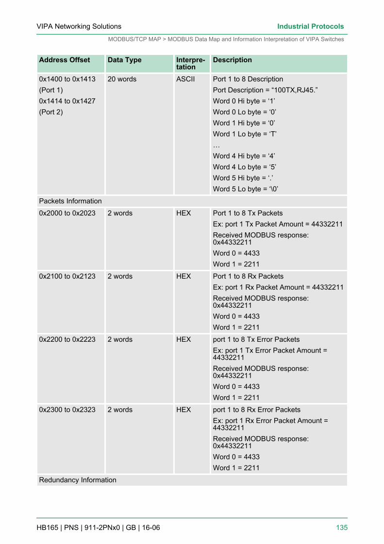
Address Offset Data Type Interpre-tation
Description
0x1400 to 0x1413(Port 1)0x1414 to 0x1427(Port 2)
20 words ASCII Port 1 to 8 DescriptionPort Description = “100TX,RJ45.”Word 0 Hi byte = ‘1’Word 0 Lo byte = ‘0’Word 1 Hi byte = ‘0’Word 1 Lo byte = ‘T’…Word 4 Hi byte = ‘4’Word 4 Lo byte = ‘5’Word 5 Hi byte = ‘.’Word 5 Lo byte = ‘\0’
Packets Information
0x2000 to 0x2023 2 words HEX Port 1 to 8 Tx PacketsEx: port 1 Tx Packet Amount = 44332211Received MODBUS response:0x44332211Word 0 = 4433Word 1 = 2211
0x2100 to 0x2123 2 words HEX Port 1 to 8 Rx PacketsEx: port 1 Rx Packet Amount = 44332211Received MODBUS response:0x44332211Word 0 = 4433Word 1 = 2211
0x2200 to 0x2223 2 words HEX port 1 to 8 Tx Error PacketsEx: port 1 Tx Error Packet Amount =44332211Received MODBUS response:0x44332211Word 0 = 4433Word 1 = 2211
0x2300 to 0x2323 2 words HEX port 1 to 8 Rx Error PacketsEx: port 1 Rx Error Packet Amount =44332211Received MODBUS response:0x44332211Word 0 = 4433Word 1 = 2211
Redundancy Information
VIPA Networking Solutions Industrial Protocols
MODBUS/TCP MAP > MODBUS Data Map and Information Interpretation of VIPA Switches
HB165 | PNS | 911-2PNx0 | GB | 16-06 135
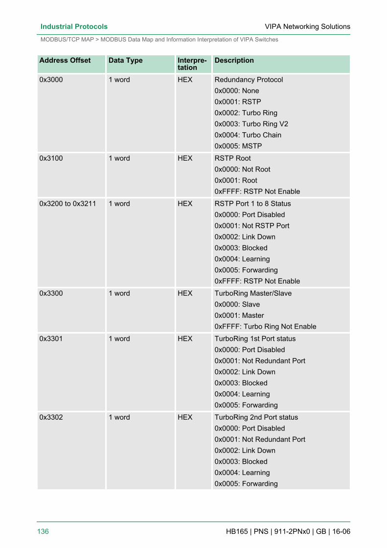
Address Offset Data Type Interpre-tation
Description
0x3000 1 word HEX Redundancy Protocol0x0000: None0x0001: RSTP0x0002: Turbo Ring0x0003: Turbo Ring V20x0004: Turbo Chain0x0005: MSTP
0x3100 1 word HEX RSTP Root0x0000: Not Root0x0001: Root0xFFFF: RSTP Not Enable
0x3200 to 0x3211 1 word HEX RSTP Port 1 to 8 Status0x0000: Port Disabled0x0001: Not RSTP Port0x0002: Link Down0x0003: Blocked0x0004: Learning0x0005: Forwarding0xFFFF: RSTP Not Enable
0x3300 1 word HEX TurboRing Master/Slave0x0000: Slave0x0001: Master0xFFFF: Turbo Ring Not Enable
0x3301 1 word HEX TurboRing 1st Port status0x0000: Port Disabled0x0001: Not Redundant Port0x0002: Link Down0x0003: Blocked0x0004: Learning0x0005: Forwarding
0x3302 1 word HEX TurboRing 2nd Port status0x0000: Port Disabled0x0001: Not Redundant Port0x0002: Link Down0x0003: Blocked0x0004: Learning0x0005: Forwarding
VIPA Networking SolutionsIndustrial Protocols
MODBUS/TCP MAP > MODBUS Data Map and Information Interpretation of VIPA Switches
HB165 | PNS | 911-2PNx0 | GB | 16-06 136
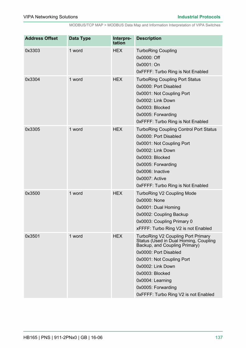
Address Offset Data Type Interpre-tation
Description
0x3303 1 word HEX TurboRing Coupling0x0000: Off0x0001: On0xFFFF: Turbo Ring is Not Enabled
0x3304 1 word HEX TurboRing Coupling Port Status0x0000: Port Disabled0x0001: Not Coupling Port0x0002: Link Down0x0003: Blocked0x0005: Forwarding0xFFFF: Turbo Ring is Not Enabled
0x3305 1 word HEX TurboRing Coupling Control Port Status0x0000: Port Disabled0x0001: Not Coupling Port0x0002: Link Down0x0003: Blocked0x0005: Forwarding0x0006: Inactive0x0007: Active0xFFFF: Turbo Ring is Not Enabled
0x3500 1 word HEX TurboRing V2 Coupling Mode0x0000: None0x0001: Dual Homing0x0002: Coupling Backup0x0003: Coupling Primary 0xFFFF: Turbo Ring V2 is not Enabled
0x3501 1 word HEX TurboRing V2 Coupling Port PrimaryStatus (Used in Dual Homing, CouplingBackup, and Coupling Primary)0x0000: Port Disabled0x0001: Not Coupling Port0x0002: Link Down0x0003: Blocked0x0004: Learning0x0005: Forwarding0xFFFF: Turbo Ring V2 is not Enabled
VIPA Networking Solutions Industrial Protocols
MODBUS/TCP MAP > MODBUS Data Map and Information Interpretation of VIPA Switches
HB165 | PNS | 911-2PNx0 | GB | 16-06 137
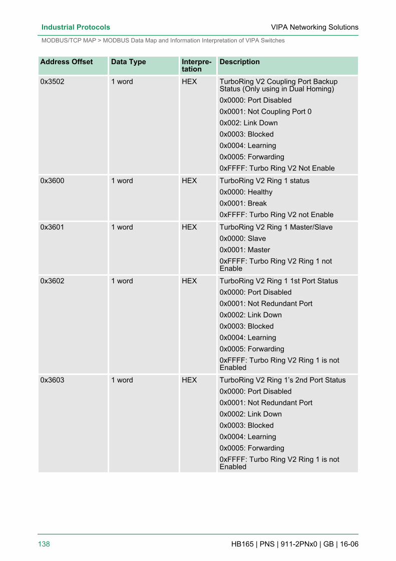
Address Offset Data Type Interpre-tation
Description
0x3502 1 word HEX TurboRing V2 Coupling Port BackupStatus (Only using in Dual Homing)0x0000: Port Disabled0x0001: Not Coupling Port 00x002: Link Down0x0003: Blocked0x0004: Learning0x0005: Forwarding0xFFFF: Turbo Ring V2 Not Enable
0x3600 1 word HEX TurboRing V2 Ring 1 status0x0000: Healthy0x0001: Break0xFFFF: Turbo Ring V2 not Enable
0x3601 1 word HEX TurboRing V2 Ring 1 Master/Slave0x0000: Slave0x0001: Master0xFFFF: Turbo Ring V2 Ring 1 notEnable
0x3602 1 word HEX TurboRing V2 Ring 1 1st Port Status0x0000: Port Disabled0x0001: Not Redundant Port0x0002: Link Down0x0003: Blocked0x0004: Learning0x0005: Forwarding0xFFFF: Turbo Ring V2 Ring 1 is notEnabled
0x3603 1 word HEX TurboRing V2 Ring 1’s 2nd Port Status0x0000: Port Disabled0x0001: Not Redundant Port0x0002: Link Down0x0003: Blocked0x0004: Learning0x0005: Forwarding0xFFFF: Turbo Ring V2 Ring 1 is notEnabled
VIPA Networking SolutionsIndustrial Protocols
MODBUS/TCP MAP > MODBUS Data Map and Information Interpretation of VIPA Switches
HB165 | PNS | 911-2PNx0 | GB | 16-06 138
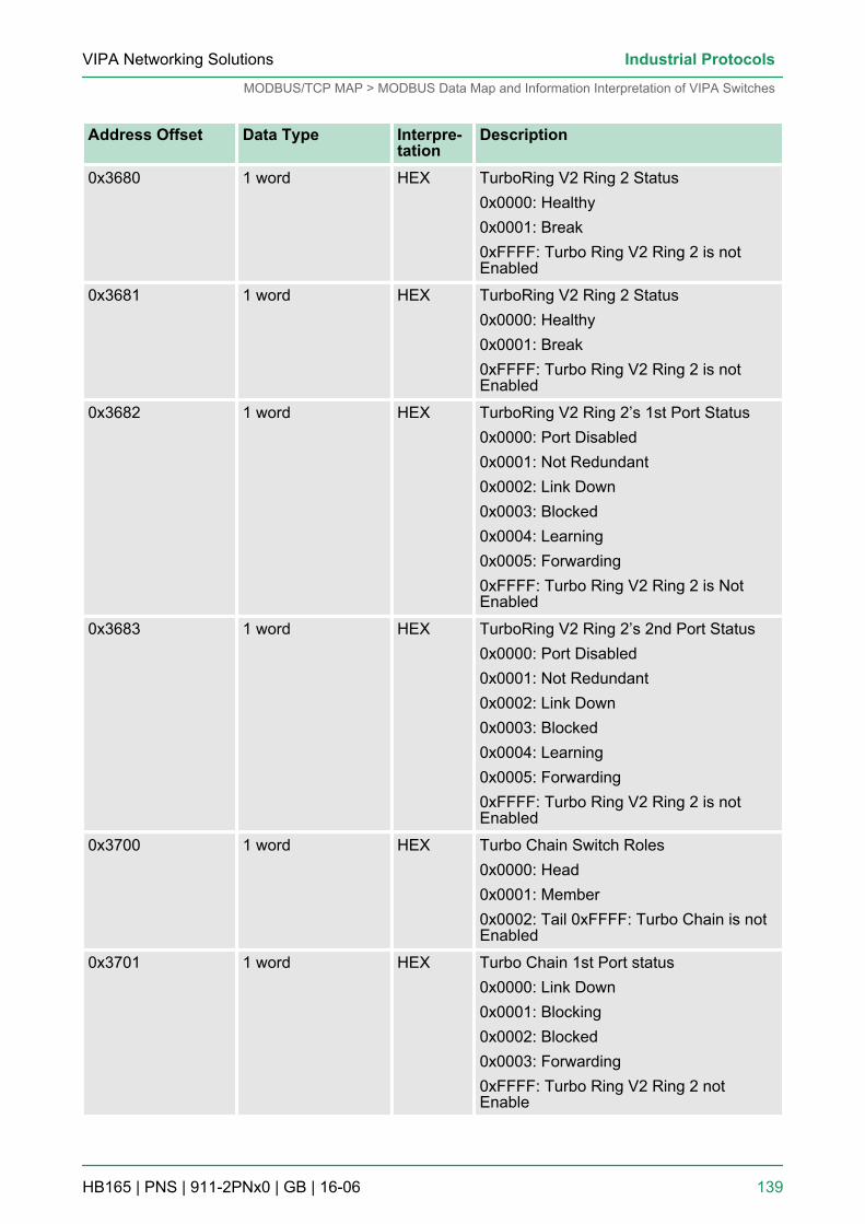
Address Offset Data Type Interpre-tation
Description
0x3680 1 word HEX TurboRing V2 Ring 2 Status0x0000: Healthy0x0001: Break0xFFFF: Turbo Ring V2 Ring 2 is notEnabled
0x3681 1 word HEX TurboRing V2 Ring 2 Status0x0000: Healthy0x0001: Break0xFFFF: Turbo Ring V2 Ring 2 is notEnabled
0x3682 1 word HEX TurboRing V2 Ring 2’s 1st Port Status0x0000: Port Disabled0x0001: Not Redundant0x0002: Link Down0x0003: Blocked0x0004: Learning0x0005: Forwarding0xFFFF: Turbo Ring V2 Ring 2 is NotEnabled
0x3683 1 word HEX TurboRing V2 Ring 2’s 2nd Port Status0x0000: Port Disabled0x0001: Not Redundant0x0002: Link Down0x0003: Blocked0x0004: Learning0x0005: Forwarding0xFFFF: Turbo Ring V2 Ring 2 is notEnabled
0x3700 1 word HEX Turbo Chain Switch Roles0x0000: Head0x0001: Member0x0002: Tail 0xFFFF: Turbo Chain is notEnabled
0x3701 1 word HEX Turbo Chain 1st Port status0x0000: Link Down0x0001: Blocking0x0002: Blocked0x0003: Forwarding0xFFFF: Turbo Ring V2 Ring 2 notEnable
VIPA Networking Solutions Industrial Protocols
MODBUS/TCP MAP > MODBUS Data Map and Information Interpretation of VIPA Switches
HB165 | PNS | 911-2PNx0 | GB | 16-06 139
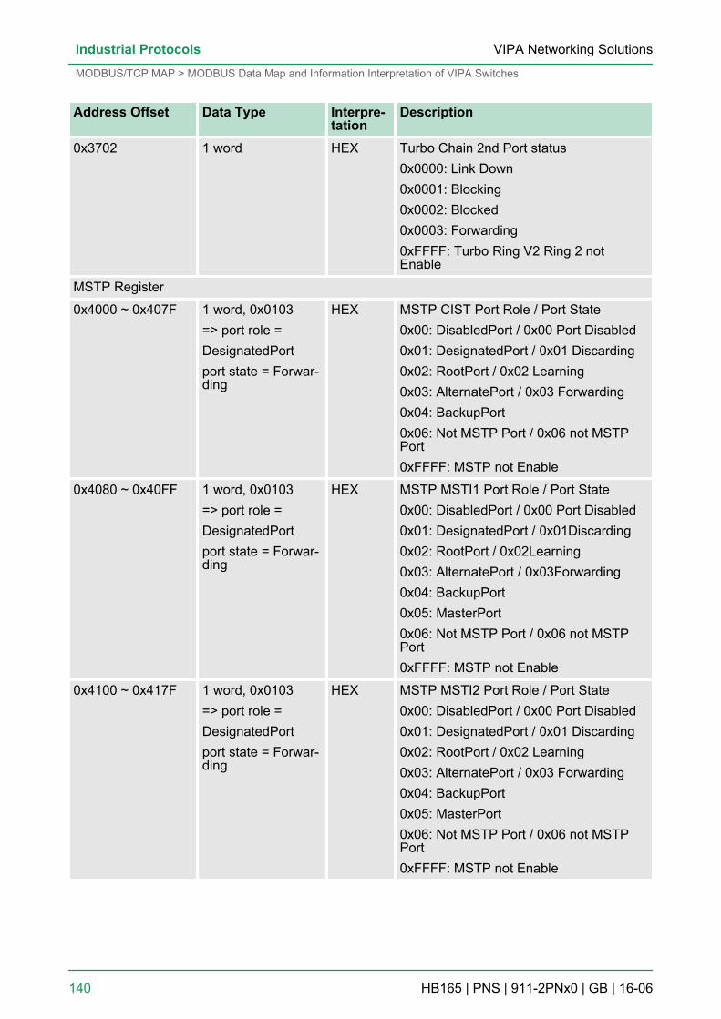
Address Offset Data Type Interpre-tation
Description
0x3702 1 word HEX Turbo Chain 2nd Port status0x0000: Link Down0x0001: Blocking0x0002: Blocked0x0003: Forwarding0xFFFF: Turbo Ring V2 Ring 2 notEnable
MSTP Register
0x4000 ~ 0x407F 1 word, 0x0103=> port role =DesignatedPortport state = Forwar-ding
HEX MSTP CIST Port Role / Port State0x00: DisabledPort / 0x00 Port Disabled0x01: DesignatedPort / 0x01 Discarding0x02: RootPort / 0x02 Learning0x03: AlternatePort / 0x03 Forwarding0x04: BackupPort0x06: Not MSTP Port / 0x06 not MSTPPort0xFFFF: MSTP not Enable
0x4080 ~ 0x40FF 1 word, 0x0103=> port role =DesignatedPortport state = Forwar-ding
HEX MSTP MSTI1 Port Role / Port State0x00: DisabledPort / 0x00 Port Disabled0x01: DesignatedPort / 0x01Discarding0x02: RootPort / 0x02Learning0x03: AlternatePort / 0x03Forwarding0x04: BackupPort0x05: MasterPort0x06: Not MSTP Port / 0x06 not MSTPPort0xFFFF: MSTP not Enable
0x4100 ~ 0x417F 1 word, 0x0103=> port role =DesignatedPortport state = Forwar-ding
HEX MSTP MSTI2 Port Role / Port State0x00: DisabledPort / 0x00 Port Disabled0x01: DesignatedPort / 0x01 Discarding0x02: RootPort / 0x02 Learning0x03: AlternatePort / 0x03 Forwarding0x04: BackupPort0x05: MasterPort0x06: Not MSTP Port / 0x06 not MSTPPort0xFFFF: MSTP not Enable
VIPA Networking SolutionsIndustrial Protocols
MODBUS/TCP MAP > MODBUS Data Map and Information Interpretation of VIPA Switches
HB165 | PNS | 911-2PNx0 | GB | 16-06 140
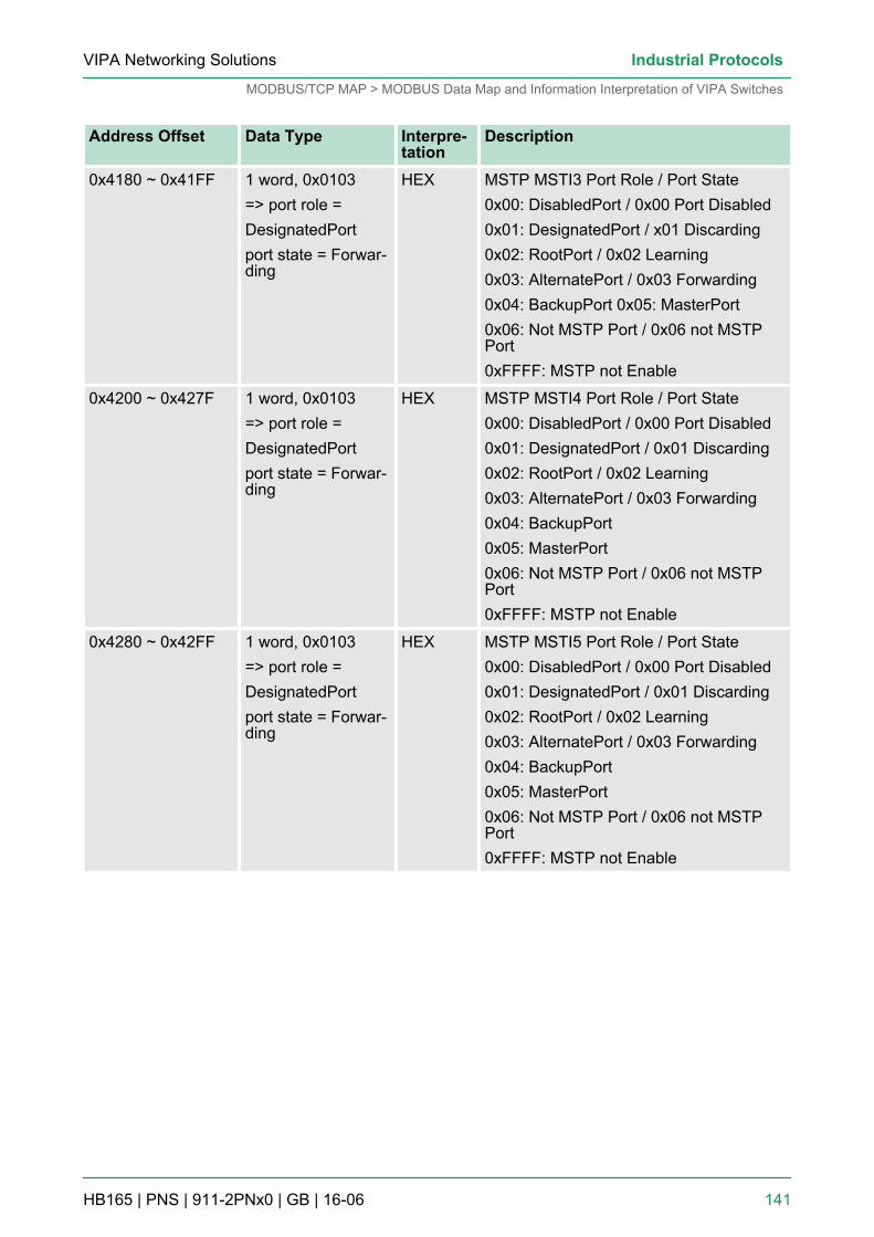
Address Offset Data Type Interpre-tation
Description
0x4180 ~ 0x41FF 1 word, 0x0103=> port role =DesignatedPortport state = Forwar-ding
HEX MSTP MSTI3 Port Role / Port State0x00: DisabledPort / 0x00 Port Disabled0x01: DesignatedPort / x01 Discarding0x02: RootPort / 0x02 Learning0x03: AlternatePort / 0x03 Forwarding0x04: BackupPort 0x05: MasterPort0x06: Not MSTP Port / 0x06 not MSTPPort0xFFFF: MSTP not Enable
0x4200 ~ 0x427F 1 word, 0x0103=> port role =DesignatedPortport state = Forwar-ding
HEX MSTP MSTI4 Port Role / Port State0x00: DisabledPort / 0x00 Port Disabled0x01: DesignatedPort / 0x01 Discarding0x02: RootPort / 0x02 Learning0x03: AlternatePort / 0x03 Forwarding0x04: BackupPort0x05: MasterPort0x06: Not MSTP Port / 0x06 not MSTPPort0xFFFF: MSTP not Enable
0x4280 ~ 0x42FF 1 word, 0x0103=> port role =DesignatedPortport state = Forwar-ding
HEX MSTP MSTI5 Port Role / Port State0x00: DisabledPort / 0x00 Port Disabled0x01: DesignatedPort / 0x01 Discarding0x02: RootPort / 0x02 Learning0x03: AlternatePort / 0x03 Forwarding0x04: BackupPort0x05: MasterPort0x06: Not MSTP Port / 0x06 not MSTPPort0xFFFF: MSTP not Enable
VIPA Networking Solutions Industrial Protocols
MODBUS/TCP MAP > MODBUS Data Map and Information Interpretation of VIPA Switches
HB165 | PNS | 911-2PNx0 | GB | 16-06 141
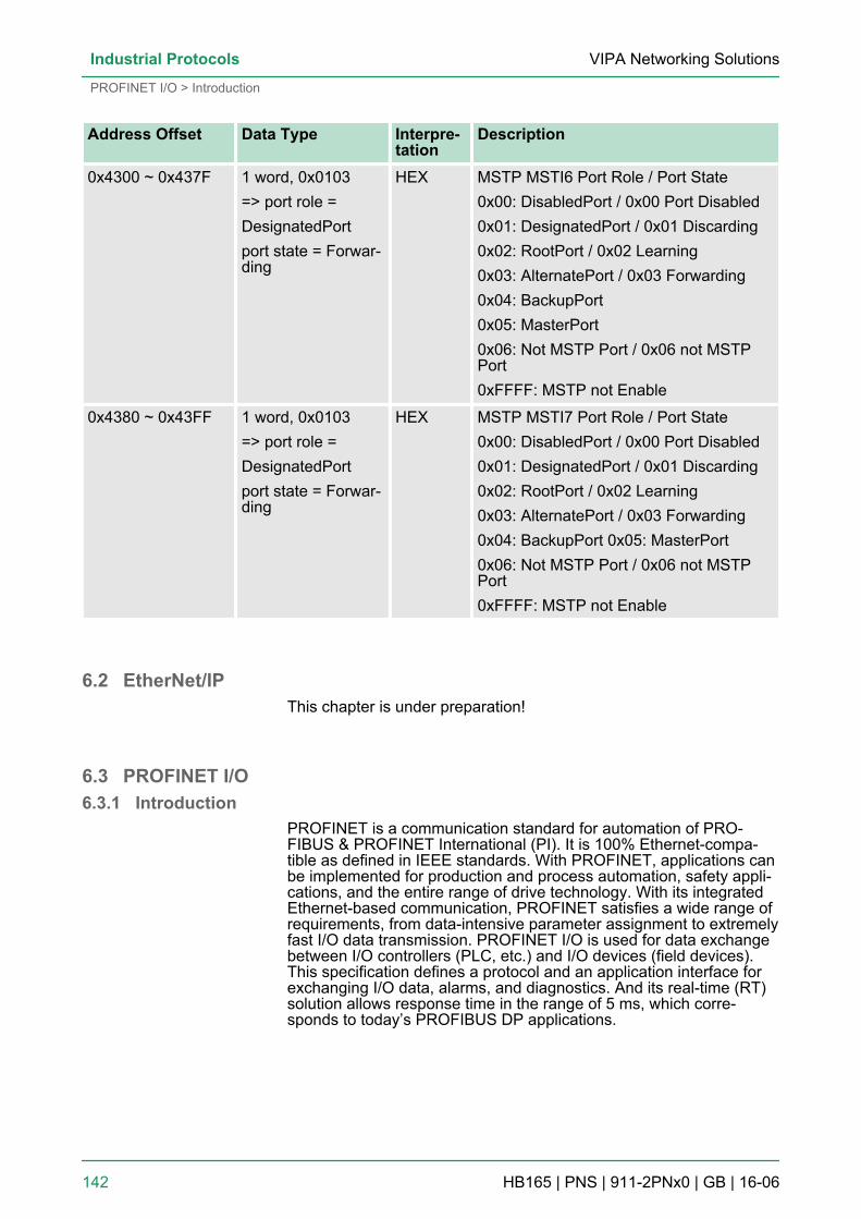
Address Offset Data Type Interpre-tation
Description
0x4300 ~ 0x437F 1 word, 0x0103=> port role =DesignatedPortport state = Forwar-ding
HEX MSTP MSTI6 Port Role / Port State0x00: DisabledPort / 0x00 Port Disabled0x01: DesignatedPort / 0x01 Discarding0x02: RootPort / 0x02 Learning0x03: AlternatePort / 0x03 Forwarding0x04: BackupPort0x05: MasterPort0x06: Not MSTP Port / 0x06 not MSTPPort0xFFFF: MSTP not Enable
0x4380 ~ 0x43FF 1 word, 0x0103=> port role =DesignatedPortport state = Forwar-ding
HEX MSTP MSTI7 Port Role / Port State0x00: DisabledPort / 0x00 Port Disabled0x01: DesignatedPort / 0x01 Discarding0x02: RootPort / 0x02 Learning0x03: AlternatePort / 0x03 Forwarding0x04: BackupPort 0x05: MasterPort0x06: Not MSTP Port / 0x06 not MSTPPort0xFFFF: MSTP not Enable
6.2 EtherNet/IPThis chapter is under preparation!
6.3 PROFINET I/O6.3.1 Introduction
PROFINET is a communication standard for automation of PRO-FIBUS & PROFINET International (PI). It is 100% Ethernet-compa-tible as defined in IEEE standards. With PROFINET, applications canbe implemented for production and process automation, safety appli-cations, and the entire range of drive technology. With its integratedEthernet-based communication, PROFINET satisfies a wide range ofrequirements, from data-intensive parameter assignment to extremelyfast I/O data transmission. PROFINET I/O is used for data exchangebetween I/O controllers (PLC, etc.) and I/O devices (field devices).This specification defines a protocol and an application interface forexchanging I/O data, alarms, and diagnostics. And its real-time (RT)solution allows response time in the range of 5 ms, which corre-sponds to today’s PROFIBUS DP applications.
VIPA Networking SolutionsIndustrial Protocols
PROFINET I/O > Introduction
HB165 | PNS | 911-2PNx0 | GB | 16-06 142
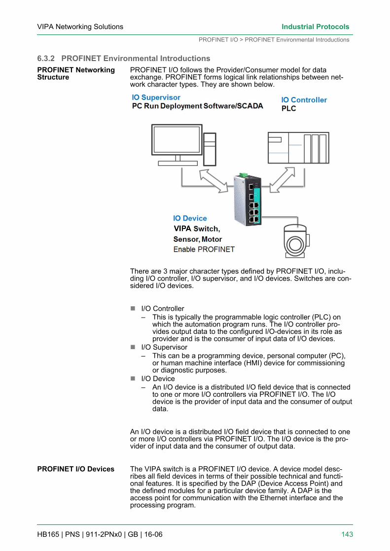
6.3.2 PROFINET Environmental IntroductionsPROFINET I/O follows the Provider/Consumer model for dataexchange. PROFINET forms logical link relationships between net-work character types. They are shown below.
There are 3 major character types defined by PROFINET I/O, inclu-ding I/O controller, I/O supervisor, and I/O devices. Switches are con-sidered I/O devices.
n I/O Controller– This is typically the programmable logic controller (PLC) on
which the automation program runs. The I/O controller pro-vides output data to the configured I/O-devices in its role asprovider and is the consumer of input data of I/O devices.
n I/O Supervisor– This can be a programming device, personal computer (PC),
or human machine interface (HMI) device for commissioningor diagnostic purposes.
n I/O Device– An I/O device is a distributed I/O field device that is connected
to one or more I/O controllers via PROFINET I/O. The I/Odevice is the provider of input data and the consumer of outputdata.
An I/O device is a distributed I/O field device that is connected to oneor more I/O controllers via PROFINET I/O. The I/O device is the pro-vider of input data and the consumer of output data.
The VIPA switch is a PROFINET I/O device. A device model desc-ribes all field devices in terms of their possible technical and functi-onal features. It is specified by the DAP (Device Access Point) andthe defined modules for a particular device family. A DAP is theaccess point for communication with the Ethernet interface and theprocessing program.
PROFINET NetworkingStructure
PROFINET I/O Devices
VIPA Networking Solutions Industrial Protocols
PROFINET I/O > PROFINET Environmental Introductions
HB165 | PNS | 911-2PNx0 | GB | 16-06 143
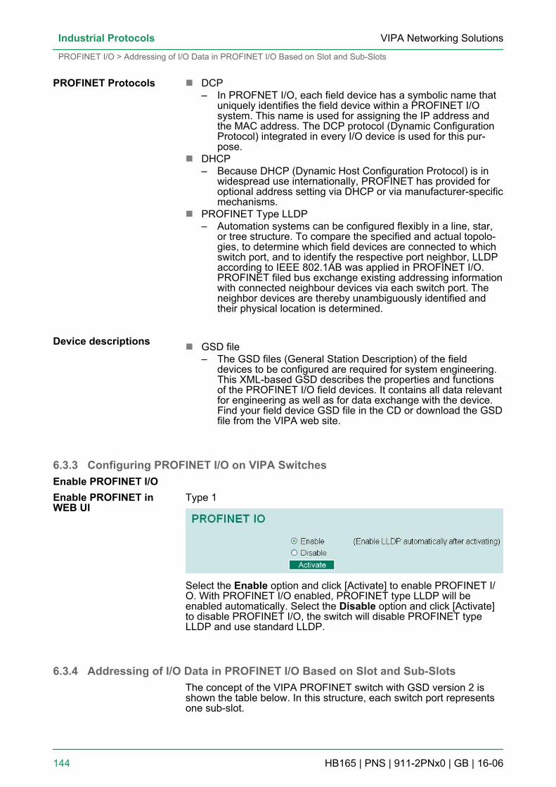
n DCP– In PROFNET I/O, each field device has a symbolic name that
uniquely identifies the field device within a PROFINET I/Osystem. This name is used for assigning the IP address andthe MAC address. The DCP protocol (Dynamic ConfigurationProtocol) integrated in every I/O device is used for this pur-pose.
n DHCP– Because DHCP (Dynamic Host Configuration Protocol) is in
widespread use internationally, PROFINET has provided foroptional address setting via DHCP or via manufacturer-specificmechanisms.
n PROFINET Type LLDP– Automation systems can be configured flexibly in a line, star,
or tree structure. To compare the specified and actual topolo-gies, to determine which field devices are connected to whichswitch port, and to identify the respective port neighbor, LLDPaccording to IEEE 802.1AB was applied in PROFINET I/O.PROFINET filed bus exchange existing addressing informationwith connected neighbour devices via each switch port. Theneighbor devices are thereby unambiguously identified andtheir physical location is determined.
n GSD file– The GSD files (General Station Description) of the field
devices to be configured are required for system engineering.This XML-based GSD describes the properties and functionsof the PROFINET I/O field devices. It contains all data relevantfor engineering as well as for data exchange with the device.Find your field device GSD file in the CD or download the GSDfile from the VIPA web site.
6.3.3 Configuring PROFINET I/O on VIPA Switches
Type 1
Select the Enable option and click [Activate] to enable PROFINET I/O. With PROFINET I/O enabled, PROFINET type LLDP will beenabled automatically. Select the Disable option and click [Activate]to disable PROFINET I/O, the switch will disable PROFINET typeLLDP and use standard LLDP.
6.3.4 Addressing of I/O Data in PROFINET I/O Based on Slot and Sub-SlotsThe concept of the VIPA PROFINET switch with GSD version 2 isshown the table below. In this structure, each switch port representsone sub-slot.
PROFINET Protocols
Device descriptions
Enable PROFINET I/OEnable PROFINET inWEB UI
VIPA Networking SolutionsIndustrial Protocols
PROFINET I/O > Addressing of I/O Data in PROFINET I/O Based on Slot and Sub-Slots
HB165 | PNS | 911-2PNx0 | GB | 16-06 144
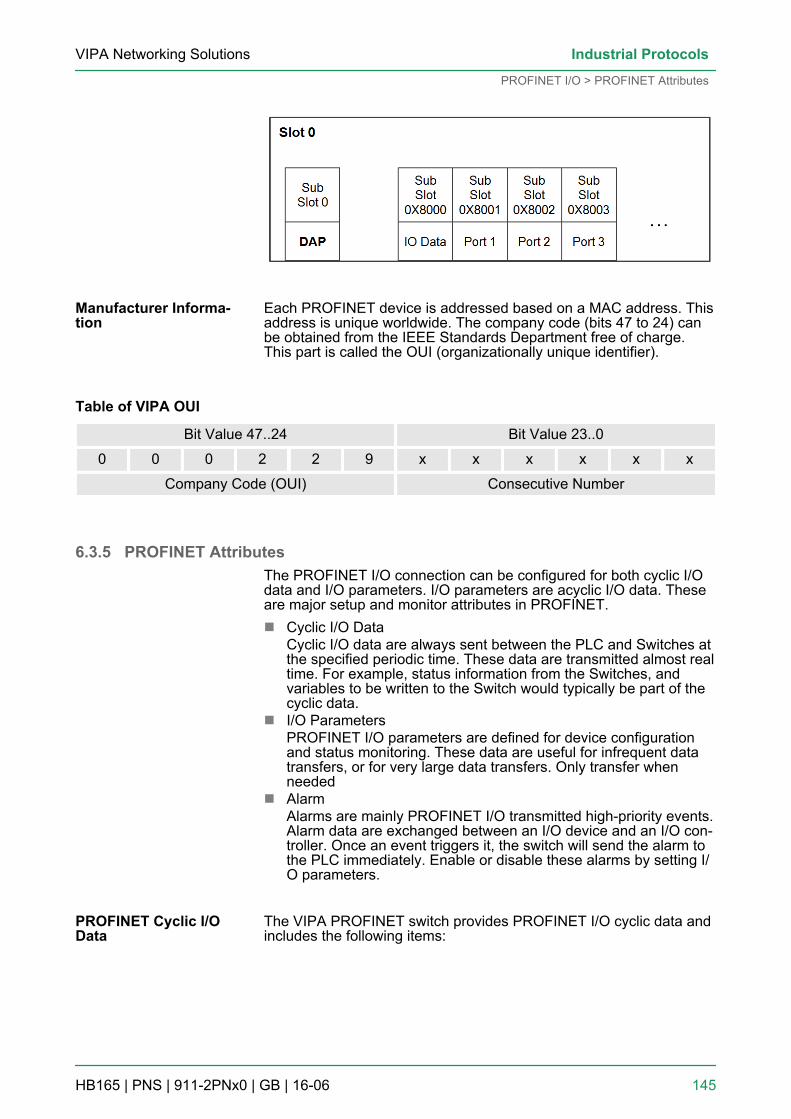
Each PROFINET device is addressed based on a MAC address. Thisaddress is unique worldwide. The company code (bits 47 to 24) canbe obtained from the IEEE Standards Department free of charge.This part is called the OUI (organizationally unique identifier).
Table of VIPA OUI
Bit Value 47..24 Bit Value 23..0
0 0 0 2 2 9 x x x x x x
Company Code (OUI) Consecutive Number
6.3.5 PROFINET AttributesThe PROFINET I/O connection can be configured for both cyclic I/Odata and I/O parameters. I/O parameters are acyclic I/O data. Theseare major setup and monitor attributes in PROFINET.n Cyclic I/O Data
Cyclic I/O data are always sent between the PLC and Switches atthe specified periodic time. These data are transmitted almost realtime. For example, status information from the Switches, andvariables to be written to the Switch would typically be part of thecyclic data.
n I/O ParametersPROFINET I/O parameters are defined for device configurationand status monitoring. These data are useful for infrequent datatransfers, or for very large data transfers. Only transfer whenneeded
n AlarmAlarms are mainly PROFINET I/O transmitted high-priority events.Alarm data are exchanged between an I/O device and an I/O con-troller. Once an event triggers it, the switch will send the alarm tothe PLC immediately. Enable or disable these alarms by setting I/O parameters.
The VIPA PROFINET switch provides PROFINET I/O cyclic data andincludes the following items:
Manufacturer Informa-tion
PROFINET Cyclic I/OData
VIPA Networking Solutions Industrial Protocols
PROFINET I/O > PROFINET Attributes
HB165 | PNS | 911-2PNx0 | GB | 16-06 145
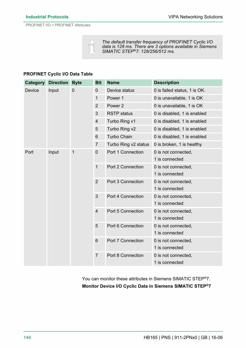
The default transfer frequency of PROFINET Cyclic I/Odata is 128 ms. There are 3 options available in SiemensSIMATIC STEP®7: 128/256/512 ms.
PROFINET Cyclic I/O Data Table
Category Direction Byte Bit Name DescriptionDevice Input 0 0 Device status 0 is failed status, 1 is OK.
1 Power 1 0 is unavailable, 1 is OK
2 Power 2 0 is unavailable, 1 is OK
3 RSTP status 0 is disabled, 1 is enabled
4 Turbo Ring v1 0 is disabled, 1 is enabled
5 Turbo Ring v2 0 is disabled, 1 is enabled
6 Turbo Chain 0 is disabled, 1 is enabled
7 Turbo Ring v2 status 0 is broken, 1 is healthy
Port Input 1 0 Port 1 Connection 0 is not connected,1 is connected
1 Port 2 Connection 0 is not connected,1 is connected
2 Port 3 Connection 0 is not connected,1 is connected
3 Port 4 Connection 0 is not connected,1 is connected
4 Port 5 Connection 0 is not connected,1 is connected
5 Port 6 Connection 0 is not connected,1 is connected
6 Port 7 Connection 0 is not connected,1 is connected
7 Port 8 Connection 0 is not connected,1 is connected
You can monitor these attributes in Siemens SIMATIC STEP®7.Monitor Device I/O Cyclic Data in Siemens SIMATIC STEP®7
VIPA Networking SolutionsIndustrial Protocols
PROFINET I/O > PROFINET Attributes
HB165 | PNS | 911-2PNx0 | GB | 16-06 146
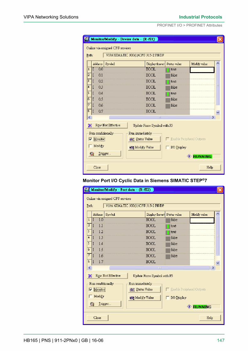
Monitor Port I/O Cyclic Data in Siemens SIMATIC STEP®7
VIPA Networking Solutions Industrial Protocols
PROFINET I/O > PROFINET Attributes
HB165 | PNS | 911-2PNx0 | GB | 16-06 147
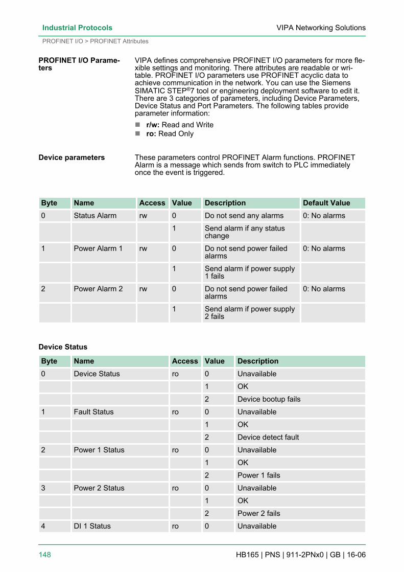
VIPA defines comprehensive PROFINET I/O parameters for more fle-xible settings and monitoring. There attributes are readable or wri-table. PROFINET I/O parameters use PROFINET acyclic data toachieve communication in the network. You can use the SiemensSIMATIC STEP®7 tool or engineering deployment software to edit it.There are 3 categories of parameters, including Device Parameters,Device Status and Port Parameters. The following tables provideparameter information:n r/w: Read and Writen ro: Read Only
These parameters control PROFINET Alarm functions. PROFINETAlarm is a message which sends from switch to PLC immediatelyonce the event is triggered.
Byte Name Access Value Description Default Value0 Status Alarm rw 0 Do not send any alarms 0: No alarms
1 Send alarm if any statuschange
1 Power Alarm 1 rw 0 Do not send power failedalarms
0: No alarms
1 Send alarm if power supply1 fails
2 Power Alarm 2 rw 0 Do not send power failedalarms
0: No alarms
1 Send alarm if power supply2 fails
Device Status
Byte Name Access Value Description0 Device Status ro 0 Unavailable
1 OK
2 Device bootup fails
1 Fault Status ro 0 Unavailable
1 OK
2 Device detect fault
2 Power 1 Status ro 0 Unavailable
1 OK
2 Power 1 fails
3 Power 2 Status ro 0 Unavailable
1 OK
2 Power 2 fails
4 DI 1 Status ro 0 Unavailable
PROFINET I/O Parame-ters
Device parameters
VIPA Networking SolutionsIndustrial Protocols
PROFINET I/O > PROFINET Attributes
HB165 | PNS | 911-2PNx0 | GB | 16-06 148
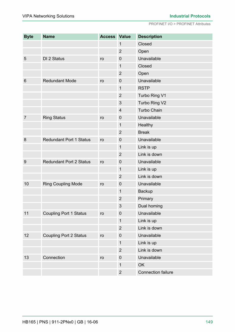
Byte Name Access Value Description 1 Closed
2 Open
5 DI 2 Status ro 0 Unavailable
1 Closed
2 Open
6 Redundant Mode ro 0 Unavailable
1 RSTP
2 Turbo Ring V1
3 Turbo Ring V2
4 Turbo Chain
7 Ring Status ro 0 Unavailable
1 Healthy
2 Break
8 Redundant Port 1 Status ro 0 Unavailable
1 Link is up
2 Link is down
9 Redundant Port 2 Status ro 0 Unavailable
1 Link is up
2 Link is down
10 Ring Coupling Mode ro 0 Unavailable
1 Backup
2 Primary
3 Dual homing
11 Coupling Port 1 Status ro 0 Unavailable
1 Link is up
2 Link is down
12 Coupling Port 2 Status ro 0 Unavailable
1 Link is up
2 Link is down
13 Connection ro 0 Unavailable
1 OK
2 Connection failure
VIPA Networking Solutions Industrial Protocols
PROFINET I/O > PROFINET Attributes
HB165 | PNS | 911-2PNx0 | GB | 16-06 149
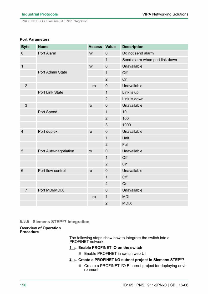
Port Parameters
Byte Name Access Value Description0 Port Alarm
rw 0 Do not send alarm
1 Send alarm when port link down
1
Port Admin Staterw 0 Unavailable
1 Off
2 On
2 ro 0 Unavailable
Port Link State 1 Link is up
2 Link is down
3 ro 0 Unavailable
Port Speed 1 10
2 100
3 1000
4 Port duplex ro 0 Unavailable
1 Half
2 Full
5 Port Auto-negotiation ro 0 Unavailable
1 Off
2 On
6 Port flow control ro 0 Unavailable
1 Off
2 On
7 Port MDI/MDIX 0 Unavailable
ro 1 MDI
2 MDIX
6.3.6 Siemens STEP®7 Integration
The following steps show how to integrate the switch into aPROFINET network:1. Enable PROFINET IO on the switch
n Enable PROFINET in switch web UI2. Create a PROFINET I/O subnet project in Siemens STEP®7
n Create a PROFINET I/O Ethernet project for deploying envi-ronment
Overview of OperationProcedure
VIPA Networking SolutionsIndustrial Protocols
PROFINET I/O > Siemens STEP®7 Integration
HB165 | PNS | 911-2PNx0 | GB | 16-06 150
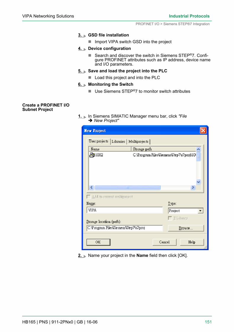
3. GSD file installationn Import VIPA switch GSD into the project
4. Device configurationn Search and discover the switch in Siemens STEP®7. Confi-
gure PROFINET attributes such as IP address, device nameand I/O parameters.
5. Save and load the project into the PLCn Load this project and into the PLC
6. Monitoring the Switchn Use Siemens STEP®7 to monitor switch attributes
1. In Siemens SIMATIC Manager menu bar, click "Fileè New Project"
2. Name your project in the Name field then click [OK].
Create a PROFINET I/OSubnet Project
VIPA Networking Solutions Industrial Protocols
PROFINET I/O > Siemens STEP®7 Integration
HB165 | PNS | 911-2PNx0 | GB | 16-06 151
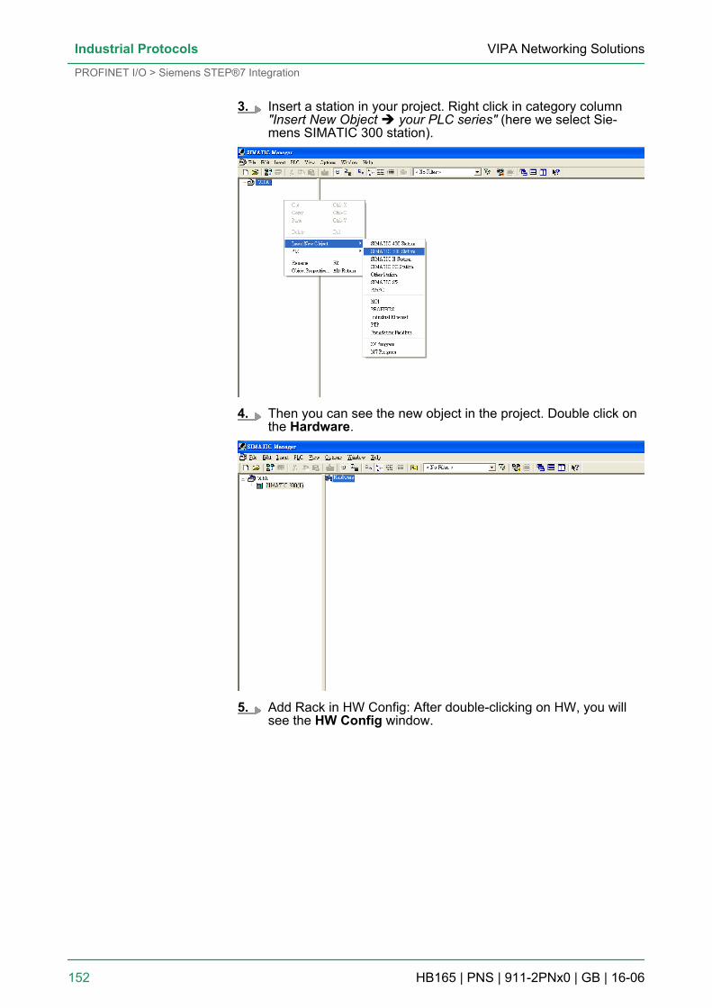
3. Insert a station in your project. Right click in category column"Insert New Object è your PLC series" (here we select Sie-mens SIMATIC 300 station).
4. Then you can see the new object in the project. Double click onthe Hardware.
5. Add Rack in HW Config: After double-clicking on HW, you willsee the HW Config window.
VIPA Networking SolutionsIndustrial Protocols
PROFINET I/O > Siemens STEP®7 Integration
HB165 | PNS | 911-2PNx0 | GB | 16-06 152
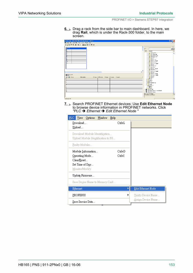
6. Drag a rack from the side bar to main dashboard. In here, wedrag Rail, which is under the Rack-300 folder, to the mainscreen.
7. Search PROFINET Ethernet devices: Use Edit Ethernet Nodeto browse device information in PROFINET networks. Click"PLC è Ethernet è Edit Ethernet Node "
VIPA Networking Solutions Industrial Protocols
PROFINET I/O > Siemens STEP®7 Integration
HB165 | PNS | 911-2PNx0 | GB | 16-06 153
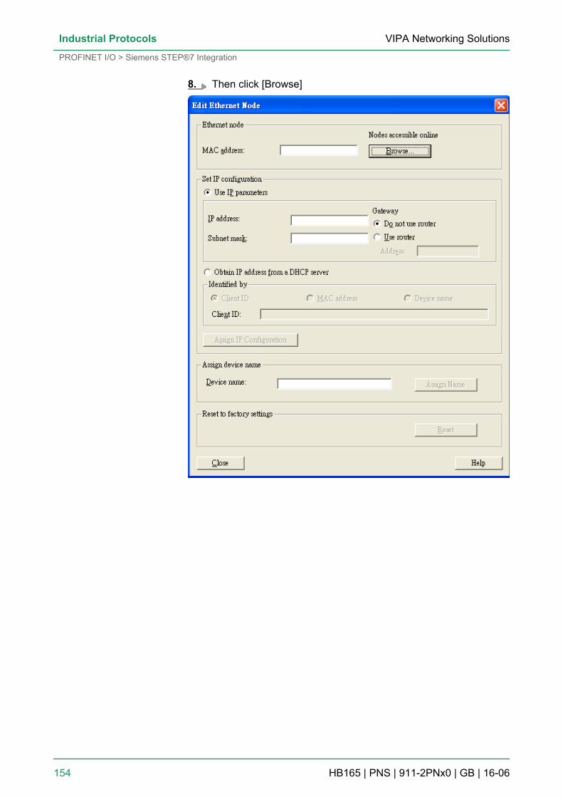
8. Then click [Browse]
VIPA Networking SolutionsIndustrial Protocols
PROFINET I/O > Siemens STEP®7 Integration
HB165 | PNS | 911-2PNx0 | GB | 16-06 154
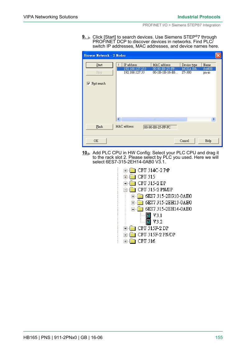
9. Click [Start] to search devices. Use Siemens STEP®7 throughPROFINET DCP to discover devices in networks. Find PLC/switch IP addresses, MAC addresses, and device names here.
10. Add PLC CPU in HW Config: Select your PLC CPU and drag itto the rack slot 2. Please select by PLC you used. Here we willselect 6ES7-315-2EH14-0AB0 V3.1.
VIPA Networking Solutions Industrial Protocols
PROFINET I/O > Siemens STEP®7 Integration
HB165 | PNS | 911-2PNx0 | GB | 16-06 155
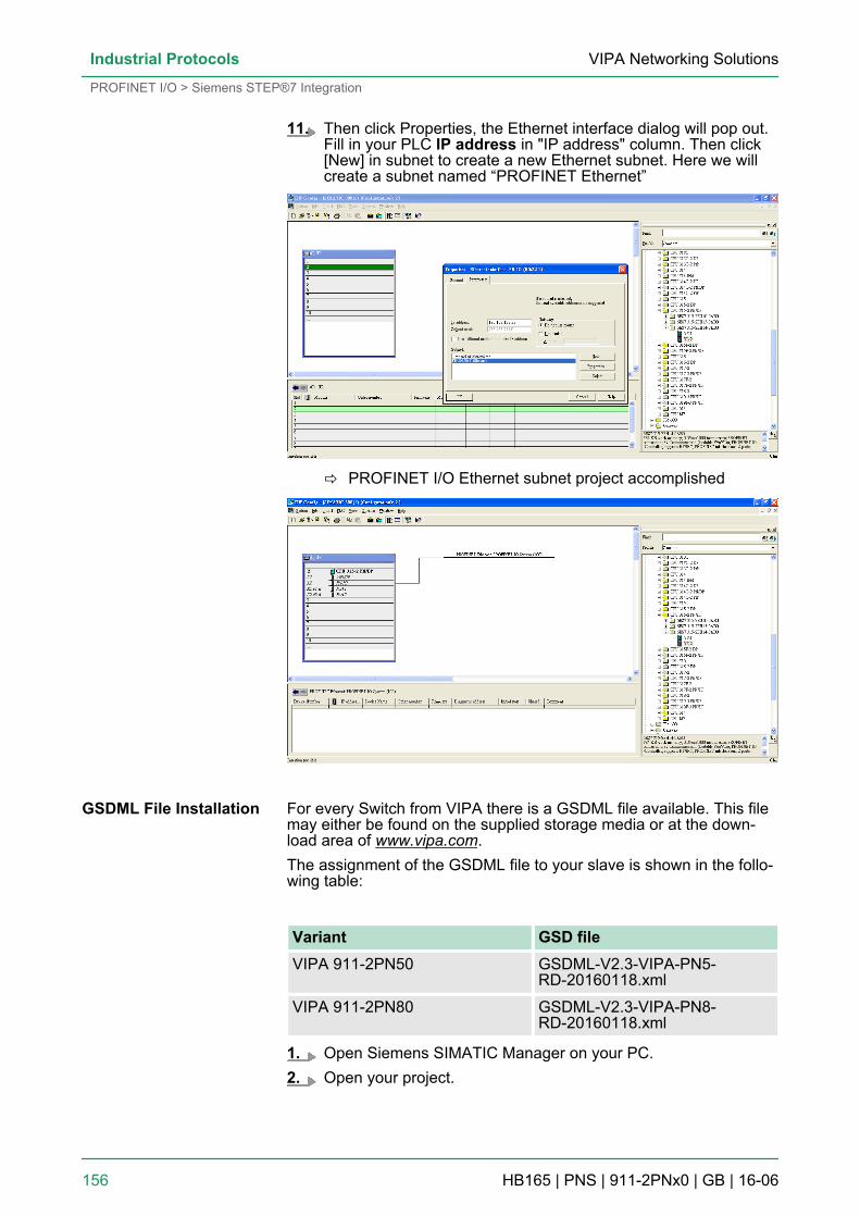
11. Then click Properties, the Ethernet interface dialog will pop out.Fill in your PLC IP address in "IP address" column. Then click[New] in subnet to create a new Ethernet subnet. Here we willcreate a subnet named “PROFINET Ethernet”
ð PROFINET I/O Ethernet subnet project accomplished
For every Switch from VIPA there is a GSDML file available. This filemay either be found on the supplied storage media or at the down-load area of www.vipa.com.The assignment of the GSDML file to your slave is shown in the follo-wing table:
Variant GSD fileVIPA 911-2PN50 GSDML-V2.3-VIPA-PN5-
RD-20160118.xml
VIPA 911-2PN80 GSDML-V2.3-VIPA-PN8-RD-20160118.xml
1. Open Siemens SIMATIC Manager on your PC.2. Open your project.
GSDML File Installation
VIPA Networking SolutionsIndustrial Protocols
PROFINET I/O > Siemens STEP®7 Integration
HB165 | PNS | 911-2PNx0 | GB | 16-06 156
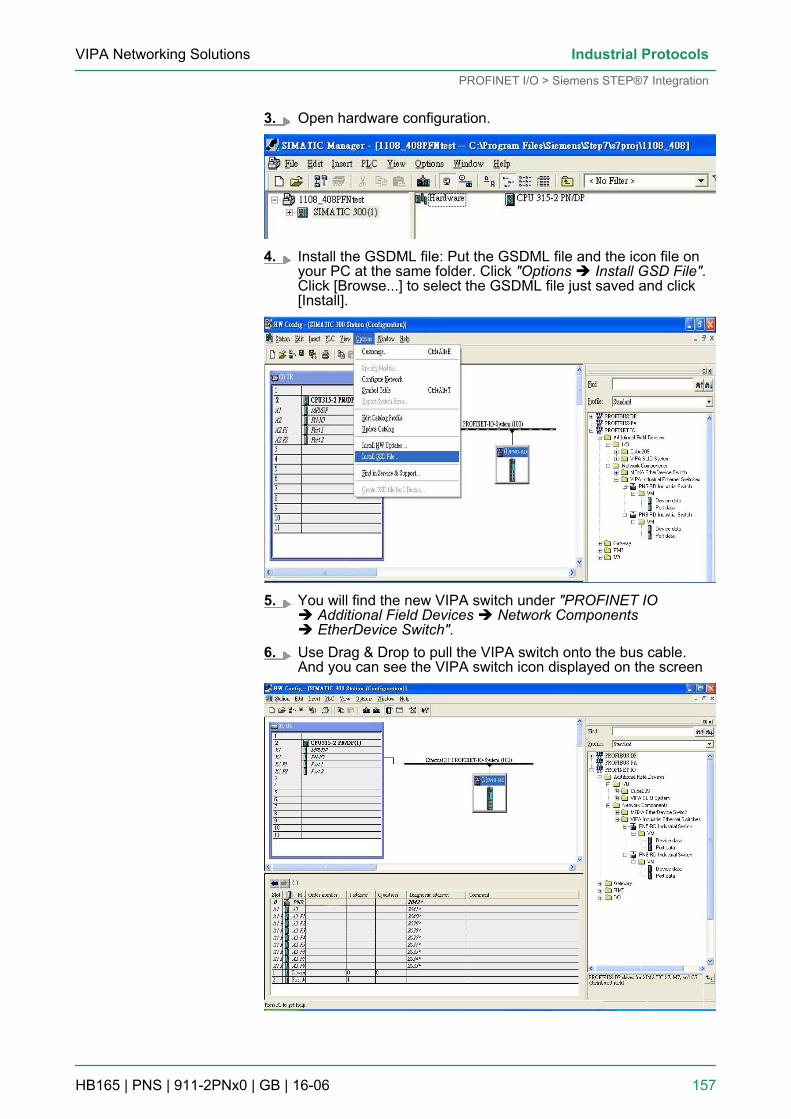
3. Open hardware configuration.
4. Install the GSDML file: Put the GSDML file and the icon file onyour PC at the same folder. Click "Options è Install GSD File".Click [Browse...] to select the GSDML file just saved and click[Install].
5. You will find the new VIPA switch under "PROFINET IOè Additional Field Devices è Network Componentsè EtherDevice Switch".
6. Use Drag & Drop to pull the VIPA switch onto the bus cable.And you can see the VIPA switch icon displayed on the screen
VIPA Networking Solutions Industrial Protocols
PROFINET I/O > Siemens STEP®7 Integration
HB165 | PNS | 911-2PNx0 | GB | 16-06 157
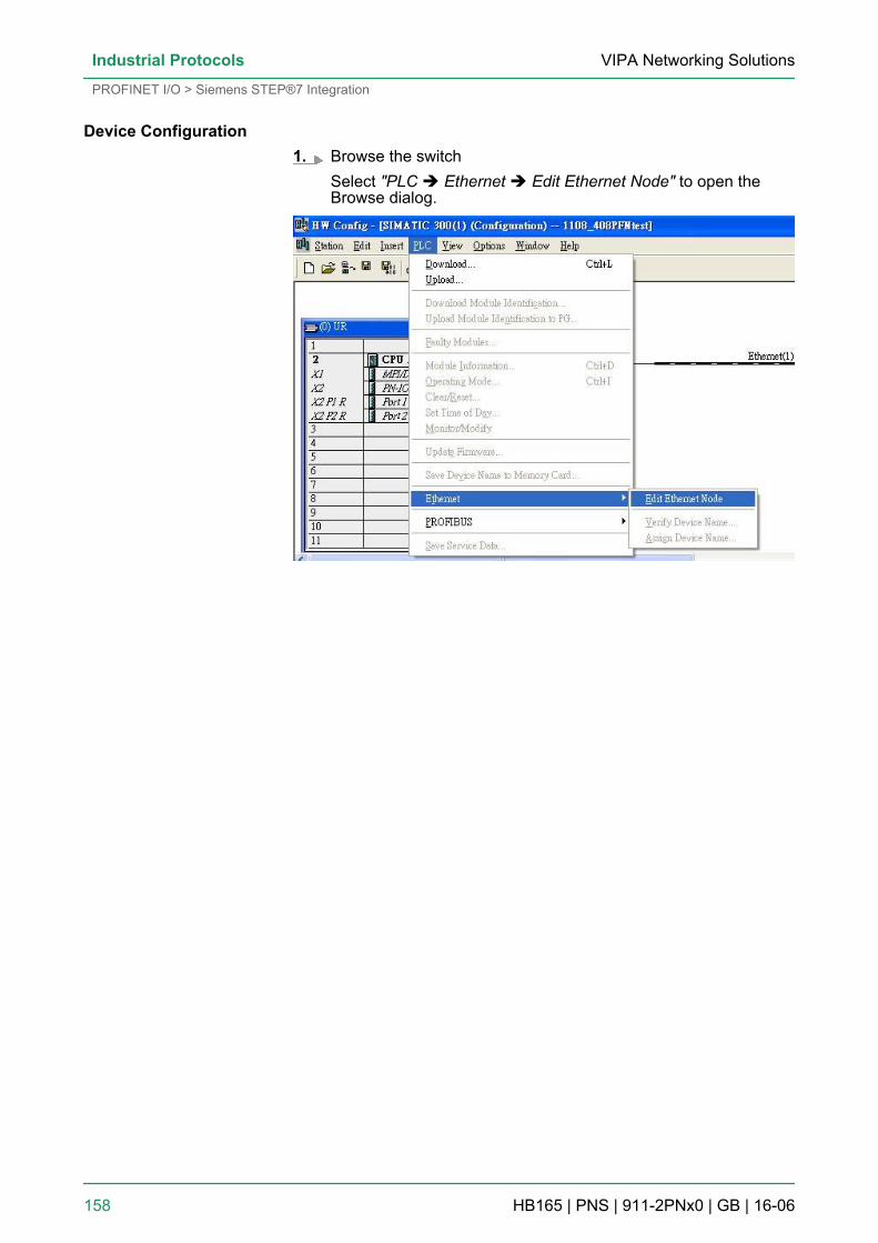
1. Browse the switchSelect "PLC è Ethernet è Edit Ethernet Node" to open theBrowse dialog.
Device Configuration
VIPA Networking SolutionsIndustrial Protocols
PROFINET I/O > Siemens STEP®7 Integration
HB165 | PNS | 911-2PNx0 | GB | 16-06 158
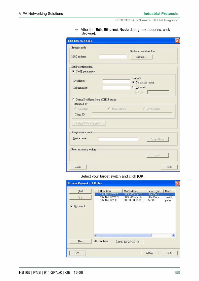
ð After the Edit Ethernet Node dialog box appears, click[Browse].
Select your target switch and click [OK]
VIPA Networking Solutions Industrial Protocols
PROFINET I/O > Siemens STEP®7 Integration
HB165 | PNS | 911-2PNx0 | GB | 16-06 159
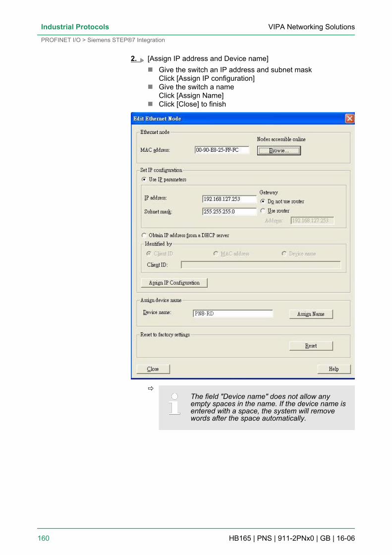
2. [Assign IP address and Device name]n Give the switch an IP address and subnet mask
Click [Assign IP configuration]n Give the switch a name
Click [Assign Name]n Click [Close] to finish
ðThe field "Device name" does not allow anyempty spaces in the name. If the device name isentered with a space, the system will removewords after the space automatically.
VIPA Networking SolutionsIndustrial Protocols
PROFINET I/O > Siemens STEP®7 Integration
HB165 | PNS | 911-2PNx0 | GB | 16-06 160
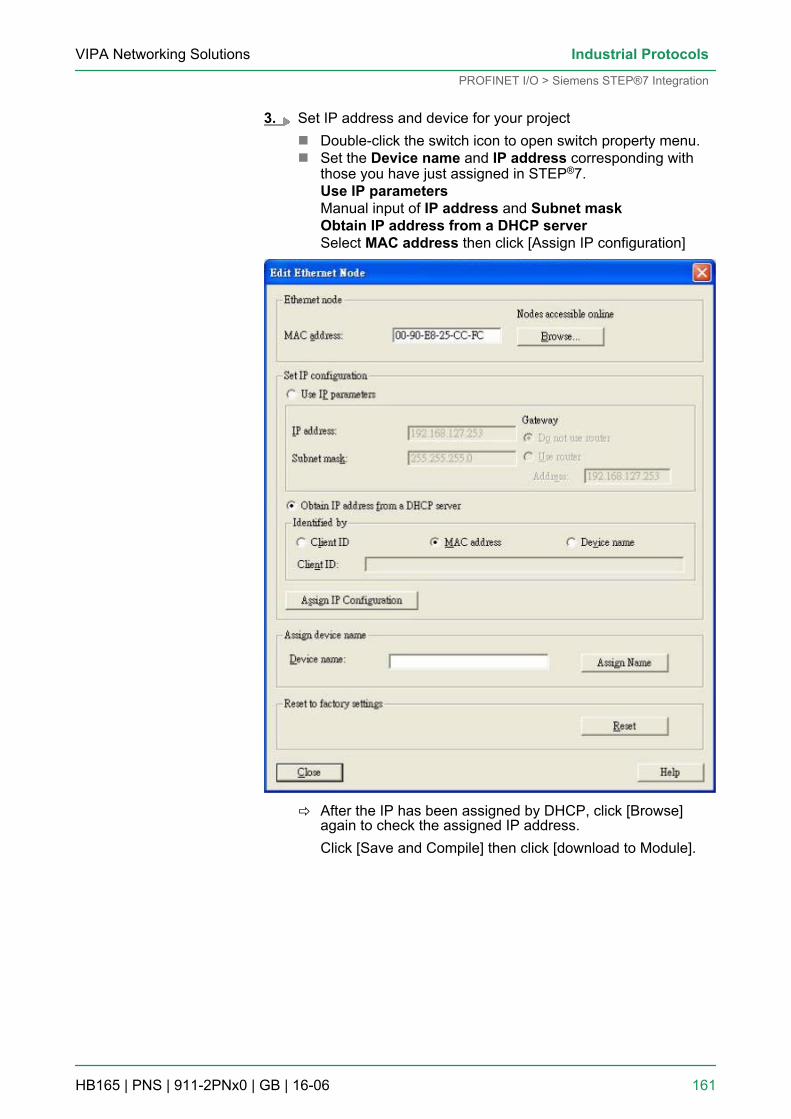
3. Set IP address and device for your projectn Double-click the switch icon to open switch property menu.n Set the Device name and IP address corresponding with
those you have just assigned in STEP®7.Use IP parametersManual input of IP address and Subnet maskObtain IP address from a DHCP serverSelect MAC address then click [Assign IP configuration]
ð After the IP has been assigned by DHCP, click [Browse]again to check the assigned IP address.Click [Save and Compile] then click [download to Module].
VIPA Networking Solutions Industrial Protocols
PROFINET I/O > Siemens STEP®7 Integration
HB165 | PNS | 911-2PNx0 | GB | 16-06 161
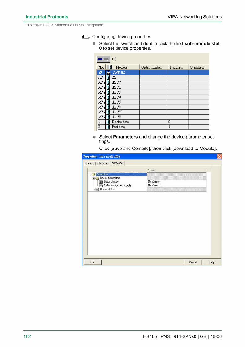
4. Configuring device propertiesn Select the switch and double-click the first sub-module slot
0 to set device properties.
ð Select Parameters and change the device parameter set-tings.Click [Save and Compile], then click [download to Module].
VIPA Networking SolutionsIndustrial Protocols
PROFINET I/O > Siemens STEP®7 Integration
HB165 | PNS | 911-2PNx0 | GB | 16-06 162
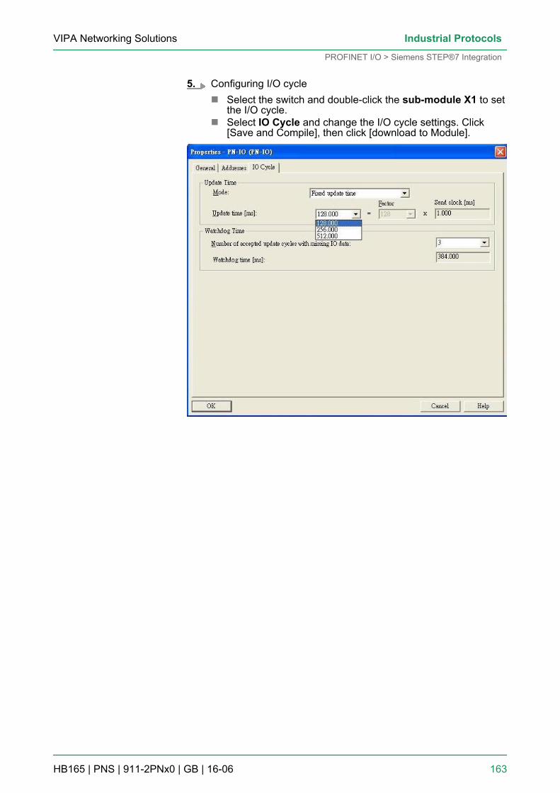
5. Configuring I/O cyclen Select the switch and double-click the sub-module X1 to set
the I/O cycle.n Select IO Cycle and change the I/O cycle settings. Click
[Save and Compile], then click [download to Module].
VIPA Networking Solutions Industrial Protocols
PROFINET I/O > Siemens STEP®7 Integration
HB165 | PNS | 911-2PNx0 | GB | 16-06 163
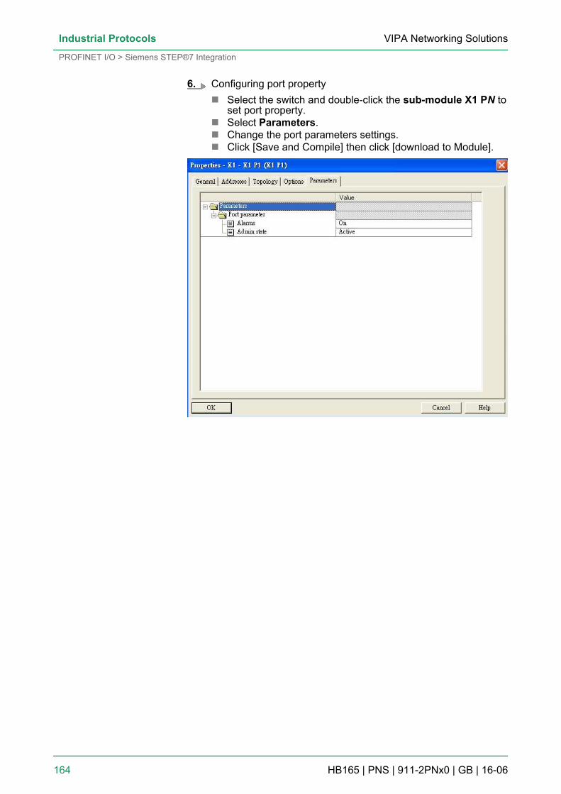
6. Configuring port propertyn Select the switch and double-click the sub-module X1 PN to
set port property.n Select Parameters.n Change the port parameters settings.n Click [Save and Compile] then click [download to Module].
VIPA Networking SolutionsIndustrial Protocols
PROFINET I/O > Siemens STEP®7 Integration
HB165 | PNS | 911-2PNx0 | GB | 16-06 164
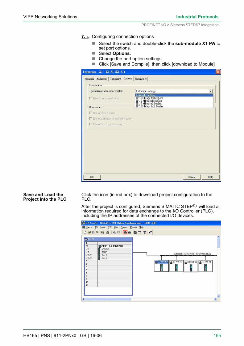
7. Configuring connection optionsn Select the switch and double-click the sub-module X1 PN to
set port options.n Select Options.n Change the port option settings.n Click [Save and Compile], then click [download to Module]
Click the icon (in red box) to download project configuration to thePLC.After the project is configured, Siemens SIMATIC STEP®7 will load allinformation required for data exchange to the I/O Controller (PLC),including the IP addresses of the connected I/O devices.
Save and Load theProject into the PLC
VIPA Networking Solutions Industrial Protocols
PROFINET I/O > Siemens STEP®7 Integration
HB165 | PNS | 911-2PNx0 | GB | 16-06 165
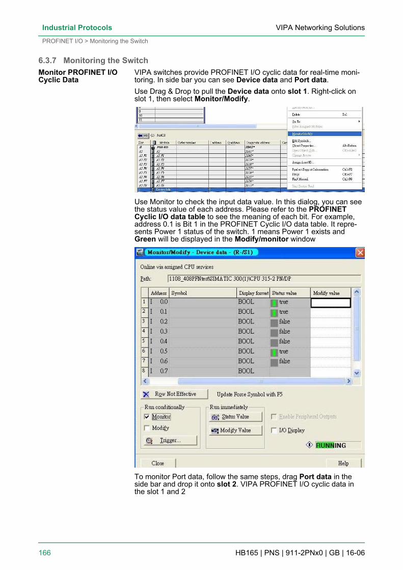
6.3.7 Monitoring the SwitchVIPA switches provide PROFINET I/O cyclic data for real-time moni-toring. In side bar you can see Device data and Port data.Use Drag & Drop to pull the Device data onto slot 1. Right-click onslot 1, then select Monitor/Modify.
Use Monitor to check the input data value. In this dialog, you can seethe status value of each address. Please refer to the PROFINETCyclic I/O data table to see the meaning of each bit. For example,address 0.1 is Bit 1 in the PROFINET Cyclic I/O data table. It repre-sents Power 1 status of the switch. 1 means Power 1 exists andGreen will be displayed in the Modify/monitor window
To monitor Port data, follow the same steps, drag Port data in theside bar and drop it onto slot 2. VIPA PROFINET I/O cyclic data inthe slot 1 and 2
Monitor PROFINET I/OCyclic Data
VIPA Networking SolutionsIndustrial Protocols
PROFINET I/O > Monitoring the Switch
HB165 | PNS | 911-2PNx0 | GB | 16-06 166
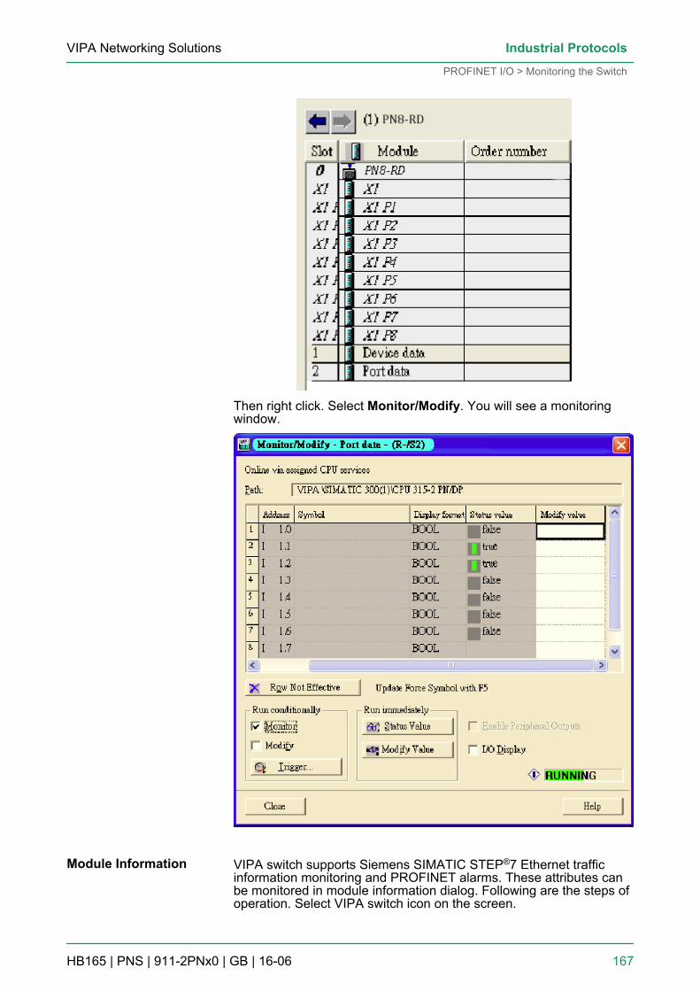
Then right click. Select Monitor/Modify. You will see a monitoringwindow.
VIPA switch supports Siemens SIMATIC STEP®7 Ethernet trafficinformation monitoring and PROFINET alarms. These attributes canbe monitored in module information dialog. Following are the steps ofoperation. Select VIPA switch icon on the screen.
Module Information
VIPA Networking Solutions Industrial Protocols
PROFINET I/O > Monitoring the Switch
HB165 | PNS | 911-2PNx0 | GB | 16-06 167
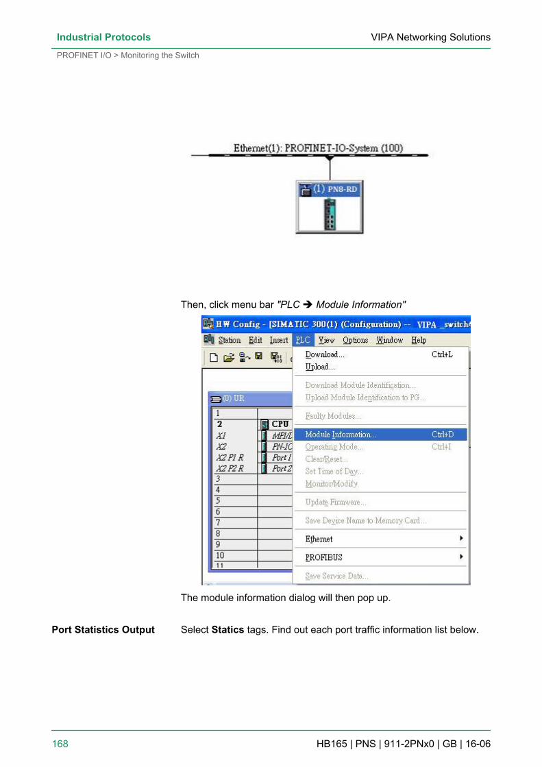
Then, click menu bar "PLC è Module Information"
The module information dialog will then pop up.
Select Statics tags. Find out each port traffic information list below.Port Statistics Output
VIPA Networking SolutionsIndustrial Protocols
PROFINET I/O > Monitoring the Switch
HB165 | PNS | 911-2PNx0 | GB | 16-06 168
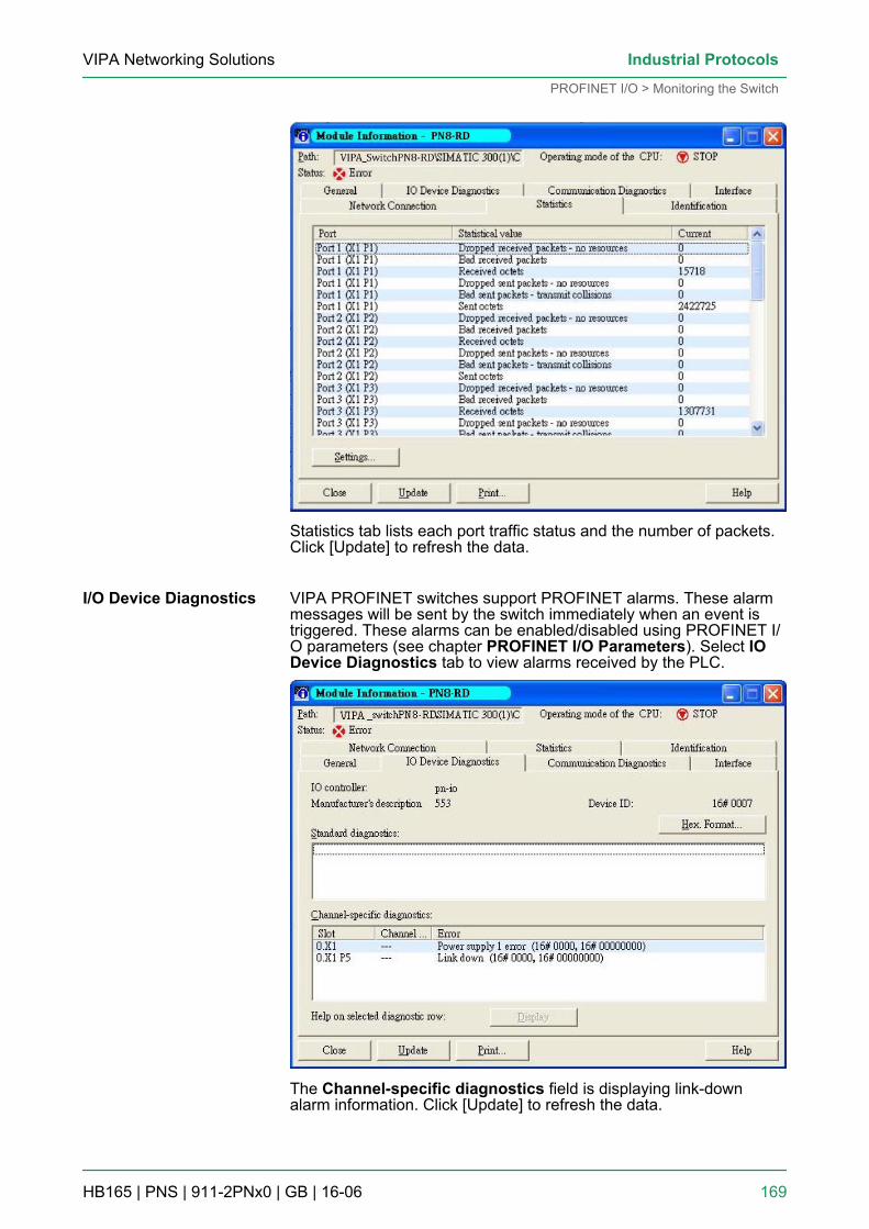
Statistics tab lists each port traffic status and the number of packets.Click [Update] to refresh the data.
VIPA PROFINET switches support PROFINET alarms. These alarmmessages will be sent by the switch immediately when an event istriggered. These alarms can be enabled/disabled using PROFINET I/O parameters (see chapter PROFINET I/O Parameters). Select IODevice Diagnostics tab to view alarms received by the PLC.
The Channel-specific diagnostics field is displaying link-downalarm information. Click [Update] to refresh the data.
I/O Device Diagnostics
VIPA Networking Solutions Industrial Protocols
PROFINET I/O > Monitoring the Switch
HB165 | PNS | 911-2PNx0 | GB | 16-06 169
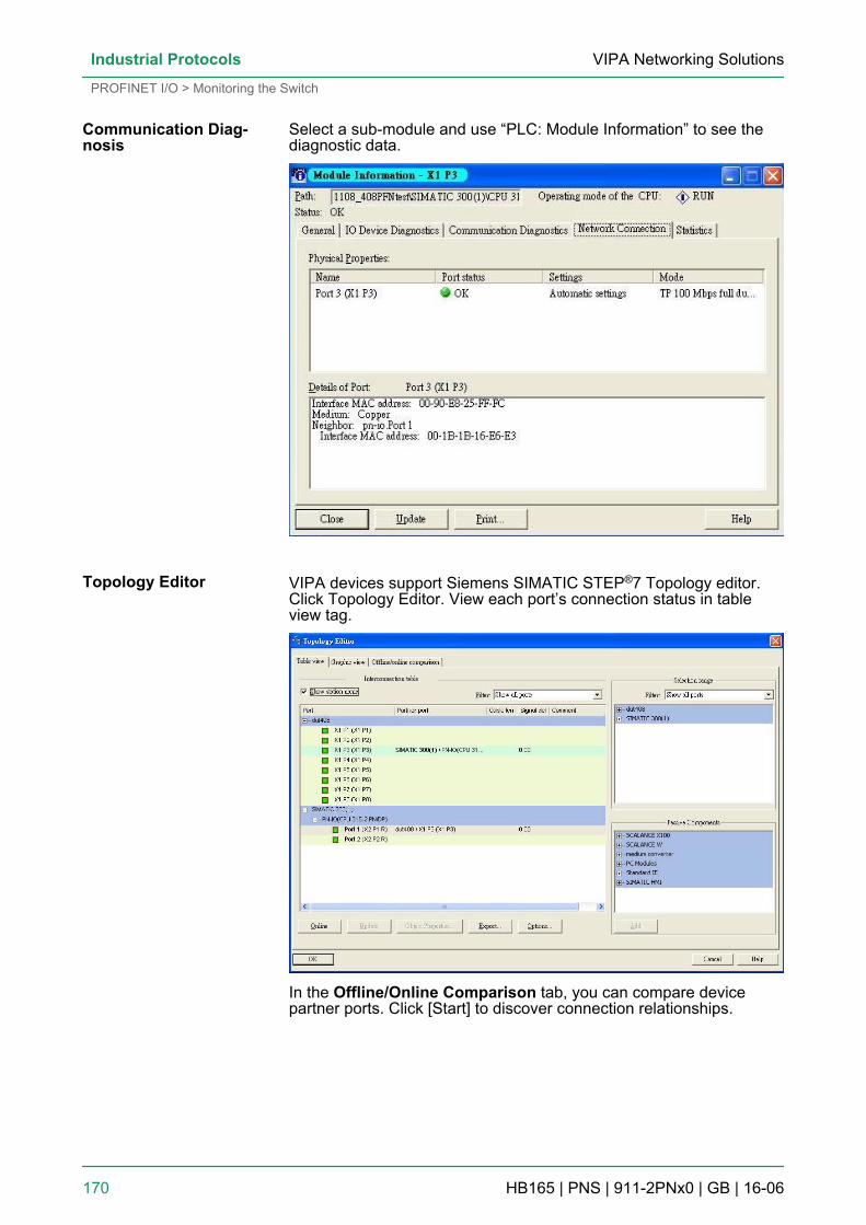
Select a sub-module and use “PLC: Module Information” to see thediagnostic data.
VIPA devices support Siemens SIMATIC STEP®7 Topology editor.Click Topology Editor. View each port’s connection status in tableview tag.
In the Offline/Online Comparison tab, you can compare devicepartner ports. Click [Start] to discover connection relationships.
Communication Diag-nosis
Topology Editor
VIPA Networking SolutionsIndustrial Protocols
PROFINET I/O > Monitoring the Switch
HB165 | PNS | 911-2PNx0 | GB | 16-06 170
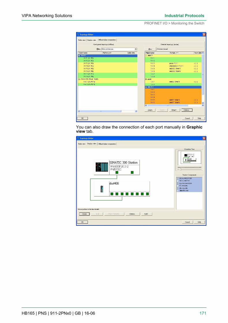
You can also draw the connection of each port manually in Graphicview tab.
VIPA Networking Solutions Industrial Protocols
PROFINET I/O > Monitoring the Switch
HB165 | PNS | 911-2PNx0 | GB | 16-06 171
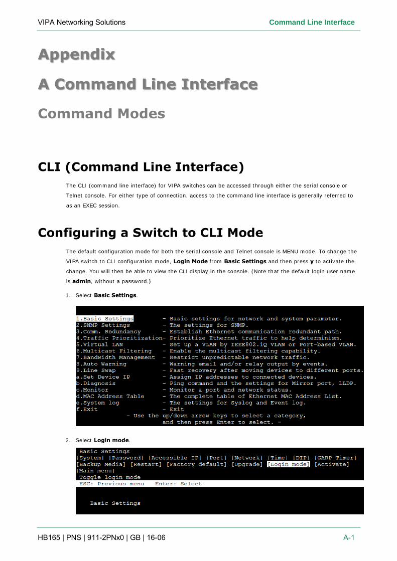
VIPA Networking Solutions Command Line Interface
HB165 | PNS | 911-2PNx0 | GB | 16-06 A-1
Appendix
A Command Line Interface
Command Modes
CLI (Command Line Interface)
The CLI (command line interface) for VIPA switches can be accessed through either the serial console or
Telnet console. For either type of connection, access to the command line interface is generally referred to
as an EXEC session.
Configuring a Switch to CLI Mode
The default configuration mode for both the serial console and Telnet console is MENU mode. To change the
VIPA switch to CLI configuration mode, Login Mode from Basic Settings and then press y to activate the
change. You will then be able to view the CLI display in the console. (Note that the default login user name
is admin, without a password.)
1. Select Basic Settings.
2. Select Login mode.
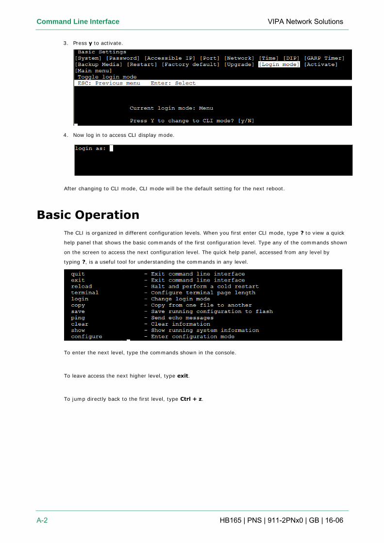
Command Line Interface VIPA Network Solutions
A-2 HB165 | PNS | 911-2PNx0 | GB | 16-06
3. Press y to activate.
4. Now log in to access CLI display mode.
After changing to CLI mode, CLI mode will be the default setting for the next reboot.
Basic Operation
The CLI is organized in different configuration levels. When you first enter CLI mode, type ? to view a quick
help panel that shows the basic commands of the first configuration level. Type any of the commands shown
on the screen to access the next configuration level. The quick help panel, accessed from any level by
typing ?, is a useful tool for understanding the commands in any level.
To enter the next level, type the commands shown in the console.
To leave access the next higher level, type exit.
To jump directly back to the first level, type Ctrl + z.
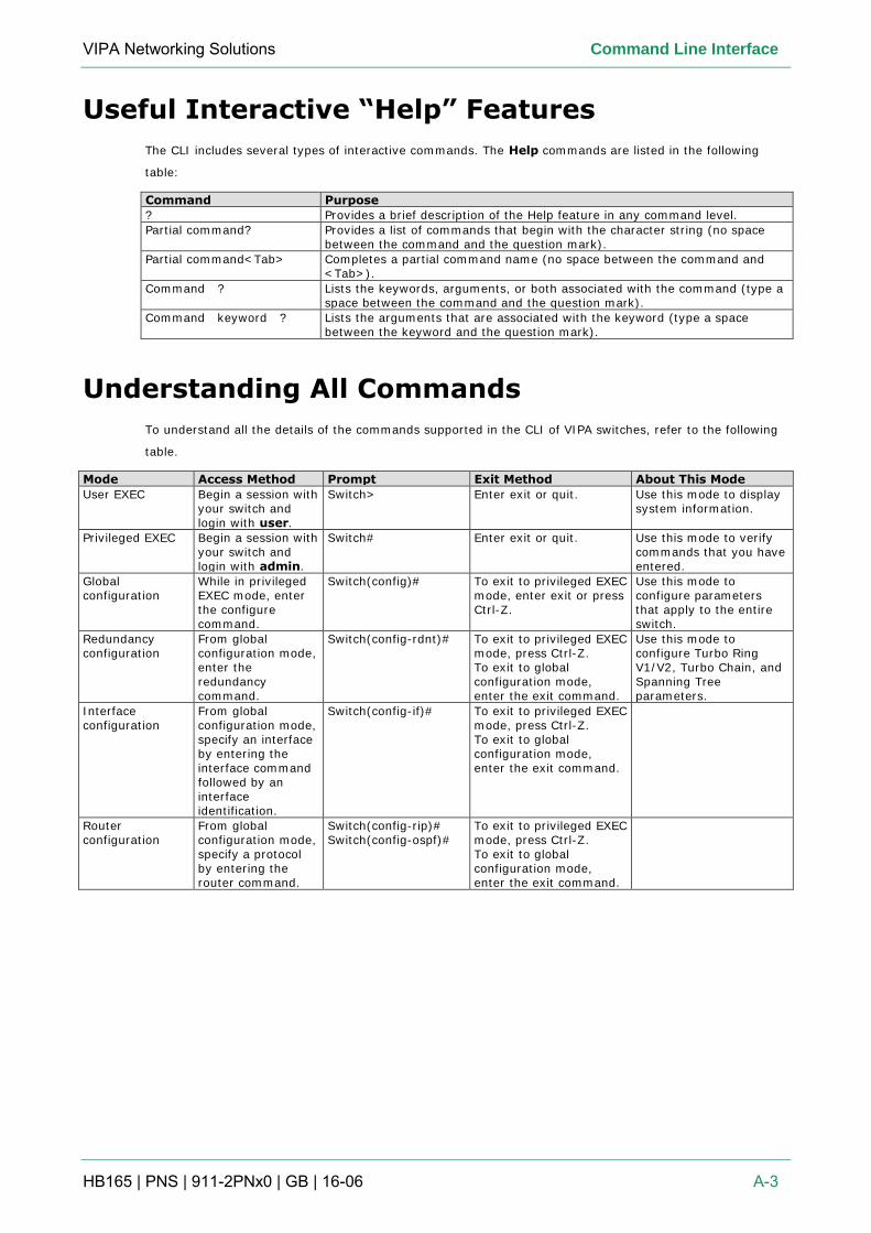
VIPA Networking Solutions Command Line Interface
HB165 | PNS | 911-2PNx0 | GB | 16-06 A-3
Useful Interactive “Help” Features
The CLI includes several types of interactive commands. The Help commands are listed in the following
table:
Command Purpose
? Provides a brief description of the Help feature in any command level.
Partial command? Provides a list of commands that begin with the character string (no space between the command and the question mark).
Partial command<Tab> Completes a partial command name (no space between the command and <Tab>).
Command ? Lists the keywords, arguments, or both associated with the command (type a space between the command and the question mark).
Command keyword ? Lists the arguments that are associated with the keyword (type a space between the keyword and the question mark).
Understanding All Commands
To understand all the details of the commands supported in the CLI of VIPA switches, refer to the following
table.
Mode Access Method Prompt Exit Method About This Mode
User EXEC Begin a session with your switch and login with user.
Switch> Enter exit or quit. Use this mode to display system information.
Privileged EXEC Begin a session with your switch and login with admin.
Switch# Enter exit or quit. Use this mode to verify commands that you have entered.
Global configuration
While in privileged EXEC mode, enter the configure command.
Switch(config)# To exit to privileged EXEC mode, enter exit or press Ctrl-Z.
Use this mode to configure parameters that apply to the entire switch.
Redundancy configuration
From global configuration mode, enter the redundancy command.
Switch(config-rdnt)# To exit to privileged EXEC mode, press Ctrl-Z. To exit to global configuration mode, enter the exit command.
Use this mode to configure Turbo Ring V1/V2, Turbo Chain, and Spanning Tree parameters.
Interface configuration
From global configuration mode, specify an interface by entering the interface command followed by an interface identification.
Switch(config-if)# To exit to privileged EXEC mode, press Ctrl-Z. To exit to global configuration mode, enter the exit command.
Router configuration
From global configuration mode, specify a protocol by entering the router command.
Switch(config-rip)# Switch(config-ospf)#
To exit to privileged EXEC mode, press Ctrl-Z. To exit to global configuration mode, enter the exit command.
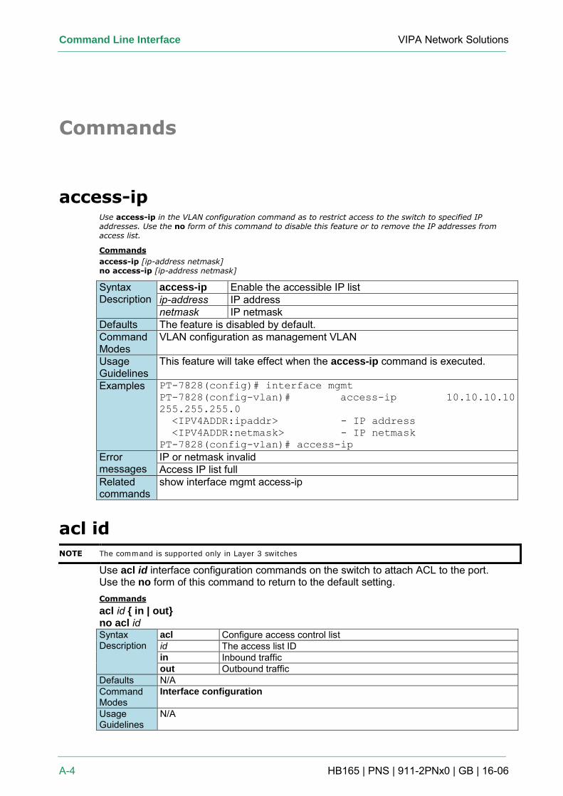
Command Line Interface VIPA Network Solutions
A-4 HB165 | PNS | 911-2PNx0 | GB | 16-06
Commands
access-ip Use access-ip in the VLAN configuration command as to restrict access to the switch to specified IP addresses. Use the no form of this command to disable this feature or to remove the IP addresses from access list.
Commands
access-ip [ip-address netmask] no access-ip [ip-address netmask]
Syntax Description
access-ip Enable the accessible IP list ip-address IP address netmask IP netmask
Defaults The feature is disabled by default. Command Modes
VLAN configuration as management VLAN
Usage Guidelines
This feature will take effect when the access-ip command is executed.
Examples PT-7828(config)# interface mgmt
PT-7828(config-vlan)# access-ip 10.10.10.10
255.255.255.0
<IPV4ADDR:ipaddr> - IP address
<IPV4ADDR:netmask> - IP netmask
PT-7828(config-vlan)# access-ip
Error messages
IP or netmask invalid Access IP list full
Related commands
show interface mgmt access-ip
acl id
NOTE The command is supported only in Layer 3 switches
Use acl id interface configuration commands on the switch to attach ACL to the port. Use the no form of this command to return to the default setting. Commands
acl id { in | out} no acl id Syntax Description
acl Configure access control list id The access list ID
in Inbound traffic
out Outbound traffic
Defaults N/A
Command Modes
Interface configuration
Usage Guidelines
N/A
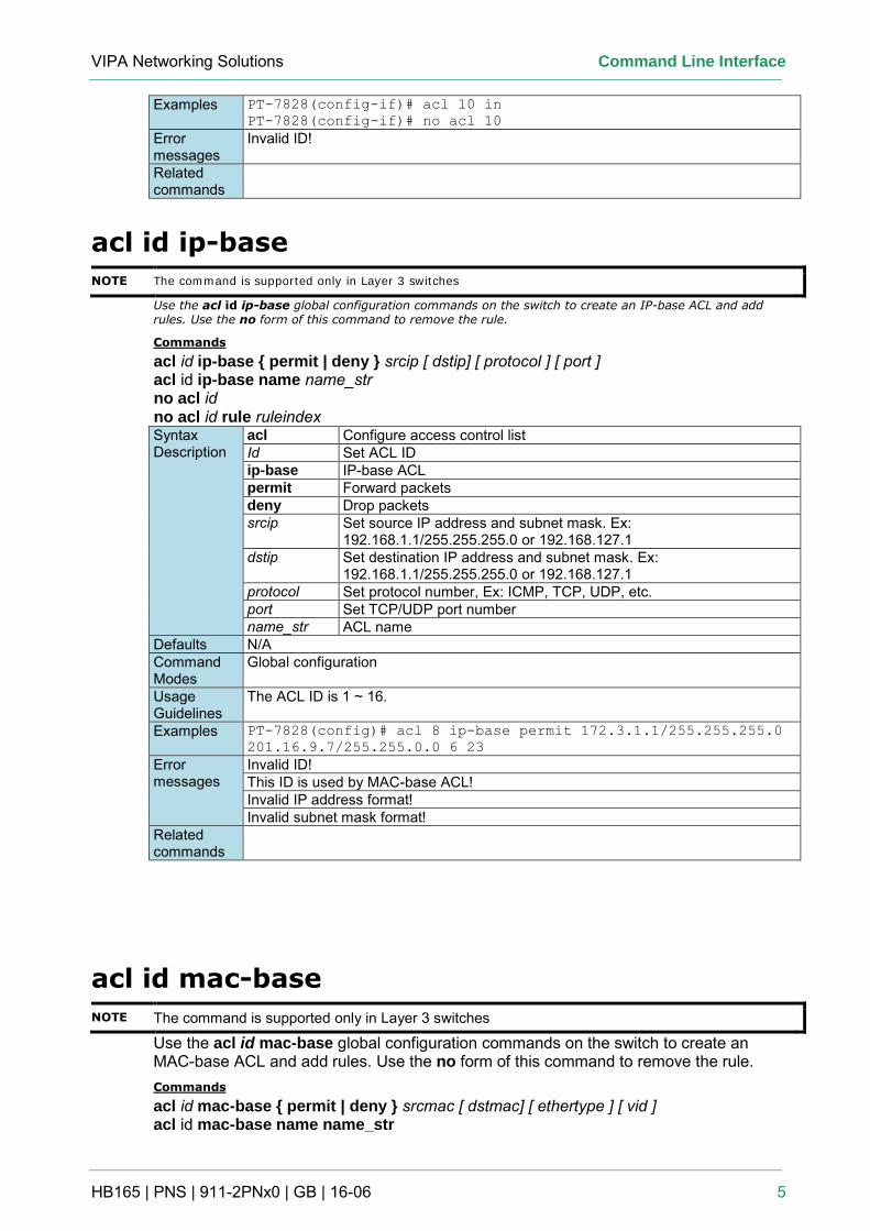
VIPA Networking Solutions Command Line Interface
HB165 | PNS | 911-2PNx0 | GB | 16-06 5
Examples PT-7828(config-if)# acl 10 in
PT-7828(config-if)# no acl 10
Error messages
Invalid ID!
Related commands
acl id ip-base
NOTE The command is supported only in Layer 3 switches Use the acl id ip-base global configuration commands on the switch to create an IP-base ACL and add rules. Use the no form of this command to remove the rule.
Commands
acl id ip-base { permit | deny } srcip [ dstip] [ protocol ] [ port ] acl id ip-base name name_str no acl id no acl id rule ruleindex Syntax Description
acl Configure access control list Id Set ACL ID
ip-base IP-base ACL
permit Forward packets
deny Drop packets
srcip Set source IP address and subnet mask. Ex: 192.168.1.1/255.255.255.0 or 192.168.127.1
dstip Set destination IP address and subnet mask. Ex: 192.168.1.1/255.255.255.0 or 192.168.127.1
protocol Set protocol number, Ex: ICMP, TCP, UDP, etc. port Set TCP/UDP port number name_str ACL name
Defaults N/A
Command Modes
Global configuration
Usage Guidelines
The ACL ID is 1 ~ 16.
Examples PT-7828(config)# acl 8 ip-base permit 172.3.1.1/255.255.255.0
201.16.9.7/255.255.0.0 6 23
Error messages
Invalid ID! This ID is used by MAC-base ACL! Invalid IP address format! Invalid subnet mask format!
Related commands
acl id mac-base
NOTE The command is supported only in Layer 3 switches
Use the acl id mac-base global configuration commands on the switch to create an MAC-base ACL and add rules. Use the no form of this command to remove the rule. Commands
acl id mac-base { permit | deny } srcmac [ dstmac] [ ethertype ] [ vid ] acl id mac-base name name_str
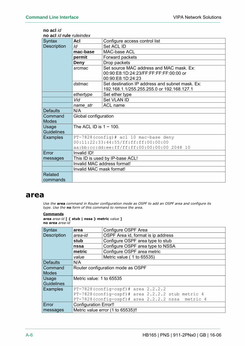
Command Line Interface VIPA Network Solutions
A-6 HB165 | PNS | 911-2PNx0 | GB | 16-06
no acl id no acl id rule ruleindex Syntax Description
Acl Configure access control list Id Set ACL ID mac-base MAC-base ACL permit Forward packets Deny Drop packets srcmac Set source MAC address and MAC mask. Ex:
00:90:E8:1D:24:23/FF:FF:FF:FF:00:00 or 00:90:E8:1D:24:23
dstmac Set destination IP address and subnet mask. Ex: 192.168.1.1/255.255.255.0 or 192.168.127.1
ethertype Set ether type Vid Set VLAN ID name_str ACL name Defaults N/A Command Modes
Global configuration
Usage Guidelines
The ACL ID is 1 ~ 100.
Examples PT-7828(config)# acl 10 mac-base deny
00:11:22:33:44:55/ff:ff:ff:00:00:00
aa:bb:cc:dd:ee:ff/ff:ff:00:00:00:00 2048 10
Error messages
Invalid ID! This ID is used by IP-base ACL!
Invalid MAC address format! Invalid MAC mask format! Related commands
area Use the area command in Router configuration mode as OSPF to add an OSPF area and configure its type. Use the no form of this command to remove the area.
Commands
area area-id [ { stub | nssa } metric value ] no area area-id
Syntax Description
area Configure OSPF Area area-id OSPF Area id, format is ip address stub Configure OSPF area type to stub nssa Configure OSPF area type to NSSA metric Configure OSPF area metric value Metric value ( 1 to 65535)
Defaults N/A Command Modes
Router configuration mode as OSPF
Usage Guidelines
Metric value: 1 to 65535
Examples PT-7828(config-ospf)# area 2.2.2.2
PT-7828(config-ospf)# area 2.2.2.2 stub metric 4
PT-7828(config-ospf)# area 2.2.2.2 nssa metric 4
Error messages
Configuration Error!! Metric value error (1 to 65535)!!
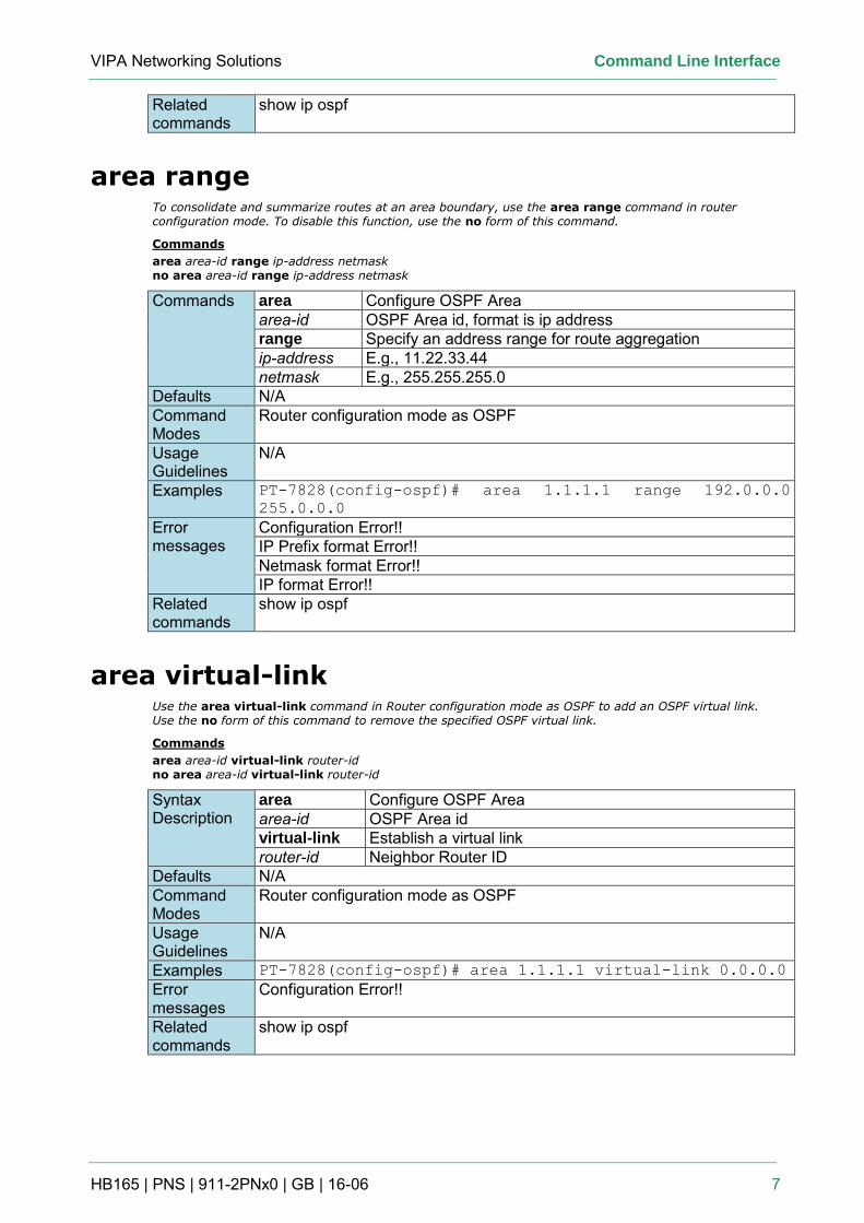
VIPA Networking Solutions Command Line Interface
HB165 | PNS | 911-2PNx0 | GB | 16-06 7
Related commands
show ip ospf
area range To consolidate and summarize routes at an area boundary, use the area range command in router configuration mode. To disable this function, use the no form of this command.
Commands
area area-id range ip-address netmask no area area-id range ip-address netmask
Commands area Configure OSPF Area area-id OSPF Area id, format is ip address range Specify an address range for route aggregation ip-address E.g., 11.22.33.44 netmask E.g., 255.255.255.0
Defaults N/A Command Modes
Router configuration mode as OSPF
Usage Guidelines
N/A
Examples PT-7828(config-ospf)# area 1.1.1.1 range 192.0.0.0
255.0.0.0
Error messages
Configuration Error!! IP Prefix format Error!! Netmask format Error!! IP format Error!!
Related commands
show ip ospf
area virtual-link Use the area virtual-link command in Router configuration mode as OSPF to add an OSPF virtual link. Use the no form of this command to remove the specified OSPF virtual link.
Commands
area area-id virtual-link router-id no area area-id virtual-link router-id
Syntax Description
area Configure OSPF Area area-id OSPF Area id virtual-link Establish a virtual link router-id Neighbor Router ID
Defaults N/A Command Modes
Router configuration mode as OSPF
Usage Guidelines
N/A
Examples PT-7828(config-ospf)# area 1.1.1.1 virtual-link 0.0.0.0
Error messages
Configuration Error!!
Related commands
show ip ospf
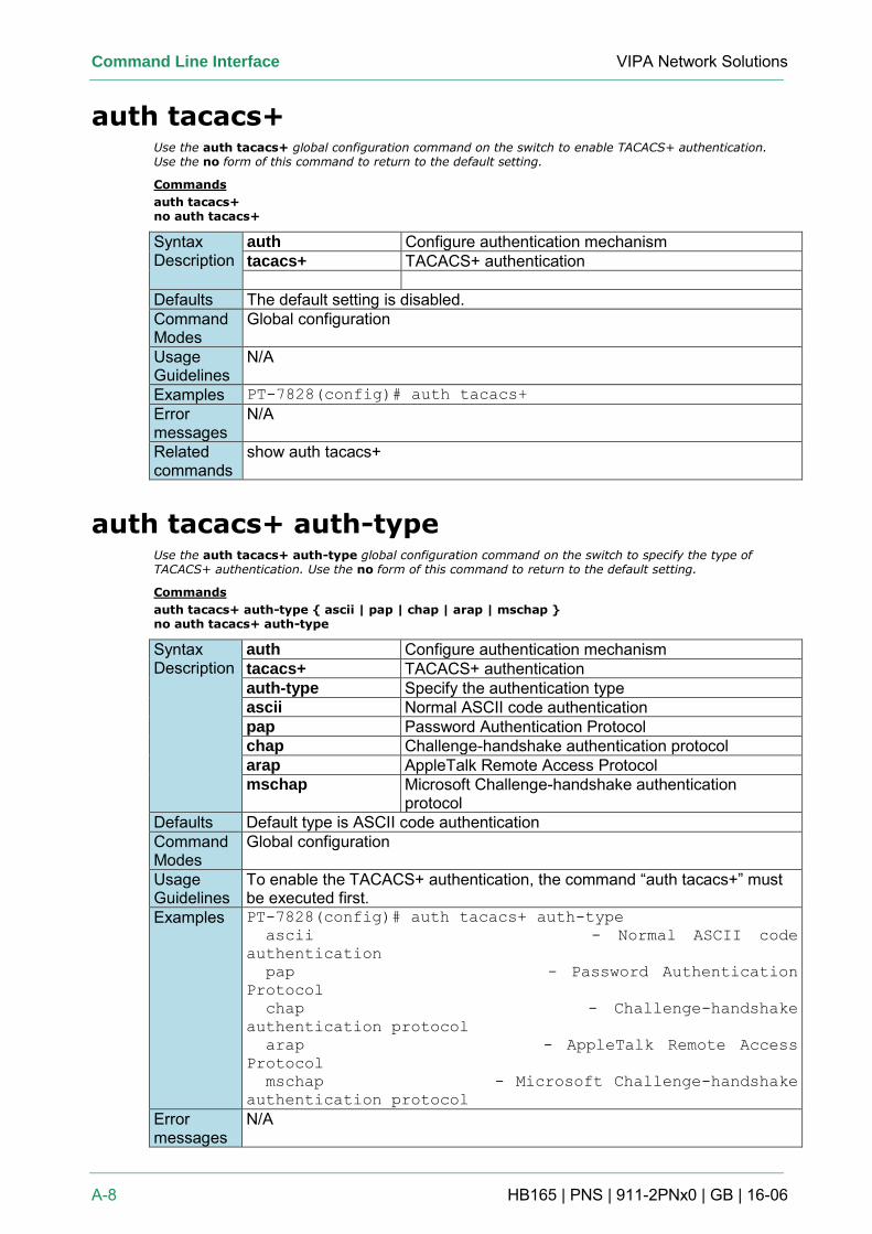
Command Line Interface VIPA Network Solutions
A-8 HB165 | PNS | 911-2PNx0 | GB | 16-06
auth tacacs+ Use the auth tacacs+ global configuration command on the switch to enable TACACS+ authentication. Use the no form of this command to return to the default setting.
Commands
auth tacacs+ no auth tacacs+
Syntax Description
auth Configure authentication mechanism tacacs+ TACACS+ authentication
Defaults The default setting is disabled. Command Modes
Global configuration
Usage Guidelines
N/A
Examples PT-7828(config)# auth tacacs+
Error messages
N/A
Related commands
show auth tacacs+
auth tacacs+ auth-type Use the auth tacacs+ auth-type global configuration command on the switch to specify the type of TACACS+ authentication. Use the no form of this command to return to the default setting.
Commands
auth tacacs+ auth-type { ascii | pap | chap | arap | mschap } no auth tacacs+ auth-type
Syntax Description
auth Configure authentication mechanism tacacs+ TACACS+ authentication auth-type Specify the authentication type ascii Normal ASCII code authentication pap Password Authentication Protocol chap Challenge-handshake authentication protocol arap AppleTalk Remote Access Protocol mschap Microsoft Challenge-handshake authentication
protocol Defaults Default type is ASCII code authentication Command Modes
Global configuration
Usage Guidelines
To enable the TACACS+ authentication, the command “auth tacacs+” must be executed first.
Examples PT-7828(config)# auth tacacs+ auth-type
ascii - Normal ASCII code
authentication
pap - Password Authentication
Protocol
chap - Challenge-handshake
authentication protocol
arap - AppleTalk Remote Access
Protocol
mschap - Microsoft Challenge-handshake
authentication protocol
Error messages
N/A
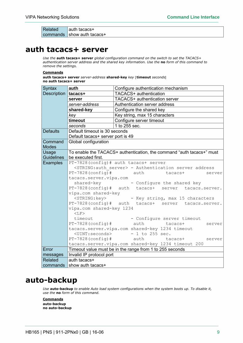
VIPA Networking Solutions Command Line Interface
HB165 | PNS | 911-2PNx0 | GB | 16-06 9
Related commands
auth tacacs+ show auth tacacs+
auth tacacs+ server Use the auth tacacs+ server global configuration command on the switch to set the TACACS+ authentication server address and the shared key information. Use the no form of this command to remove the settings.
Commands
auth tacacs+ server server-address shared-key key [timeout seconds] no auth tacacs+ server
Syntax Description
auth Configure authentication mechanism tacacs+ TACACS+ authentication server TACACS+ authentication server server-address Authentication server address shared-key Configure the shared key key Key string, max 15 characters timeout Configure server timeout seconds 1 to 255 sec.
Defaults Default timeout is 30 seconds Default tacacs+ server port is 49
Command Modes
Global configuration
Usage Guidelines
To enable the TACACS+ authentication, the command “auth tacacs+” must be executed first.
Examples PT-7828(config)# auth tacacs+ server
<STRING:auth_server> - Authentication server address
PT-7828(config)# auth tacacs+ server
tacacs.server.vipa.com
shared-key - Configure the shared key
PT-7828(config)# auth tacacs+ server tacacs.server.
vipa.com shared-key
<STRING:key> - Key string, max 15 characters
PT-7828(config)# auth tacacs+ server tacacs.server.
vipa.com shared-key 1234
<LF>
timeout - Configure server timeout
PT-7828(config)# auth tacacs+ server
tacacs.server.vipa.com shared-key 1234 timeout
<UINT:seconds> - 1 to 255 sec.
PT-7828(config)# auth tacacs+ server
tacacs.server.vipa.com shared-key 1234 timeout 200
Error messages
Timeout value must be in the range from 1 to 255 seconds Invalid IP protocol port
Related commands
auth tacacs+ show auth tacacs+
auto-backup Use auto-backup to enable Auto load system configurations when the system boots up. To disable it, use the no form of this command.
Commands
auto-backup
no auto-backup
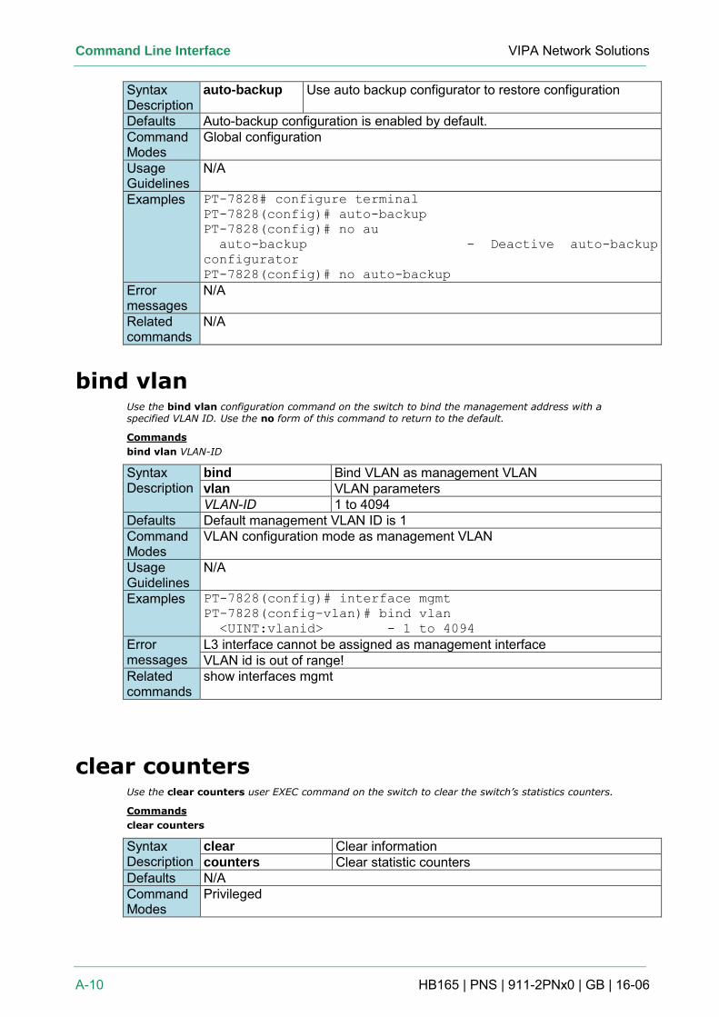
Command Line Interface VIPA Network Solutions
A-10 HB165 | PNS | 911-2PNx0 | GB | 16-06
Syntax Description
auto-backup Use auto backup configurator to restore configuration
Defaults Auto-backup configuration is enabled by default. Command Modes
Global configuration
Usage Guidelines
N/A
Examples PT-7828# configure terminal
PT-7828(config)# auto-backup
PT-7828(config)# no au
auto-backup - Deactive auto-backup
configurator
PT-7828(config)# no auto-backup
Error messages
N/A
Related commands
N/A
bind vlan Use the bind vlan configuration command on the switch to bind the management address with a specified VLAN ID. Use the no form of this command to return to the default.
Commands
bind vlan VLAN-ID
Syntax Description
bind Bind VLAN as management VLAN vlan VLAN parameters VLAN-ID 1 to 4094
Defaults Default management VLAN ID is 1 Command Modes
VLAN configuration mode as management VLAN
Usage Guidelines
N/A
Examples PT-7828(config)# interface mgmt
PT-7828(config-vlan)# bind vlan
<UINT:vlanid> - 1 to 4094
Error messages
L3 interface cannot be assigned as management interface VLAN id is out of range!
Related commands
show interfaces mgmt
clear counters Use the clear counters user EXEC command on the switch to clear the switch’s statistics counters.
Commands
clear counters
Syntax Description
clear Clear information counters Clear statistic counters
Defaults N/A Command Modes
Privileged
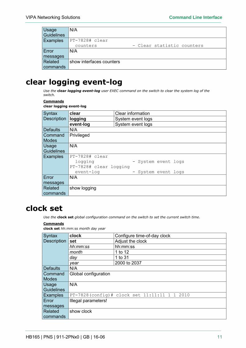
VIPA Networking Solutions Command Line Interface
HB165 | PNS | 911-2PNx0 | GB | 16-06 11
Usage Guidelines
N/A
Examples PT-7828# clear
counters - Clear statistic counters
Error messages
N/A
Related commands
show interfaces counters
clear logging event-log Use the clear logging event-log user EXEC command on the switch to clear the system log of the switch.
Commands
clear logging event-log
Syntax Description
clear Clear information logging System event logs event-log System event logs
Defaults N/A Command Modes
Privileged
Usage Guidelines
N/A
Examples PT-7828# clear
logging - System event logs
PT-7828# clear logging
event-log - System event logs
Error messages
N/A
Related commands
show logging
clock set Use the clock set global configuration command on the switch to set the current switch time.
Commands
clock set hh:mm:ss month day year
Syntax Description
clock Configure time-of-day clock set Adjust the clock hh:mm:ss hh:mm:ss month 1 to 12 day 1 to 31 year 2000 to 2037
Defaults N/A Command Modes
Global configuration
Usage Guidelines
N/A
Examples PT-7828(config)# clock set 11:11:11 1 1 2010
Error messages
Illegal parameters!
Related commands
show clock
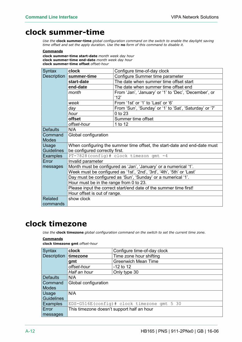
Command Line Interface VIPA Network Solutions
A-12 HB165 | PNS | 911-2PNx0 | GB | 16-06
clock summer-time Use the clock summer-time global configuration command on the switch to enable the daylight saving time offset and set the apply duration. Use the no form of this command to disable it.
Commands
clock summer-time start-date month week day hour clock summer-time end-date month week day hour clock summer-time offset offset-hour
Syntax Description
clock Configure time-of-day clock summer-time Configure Summer time parameter start-date The date when summer time offset start end-date The date when summer time offset end month From ‘Jan’, ‘January’ or ‘1’ to ‘Dec’, ‘December’, or
‘12’ week From ‘1st’ or ‘1’ to ‘Last’ or ‘6’ day From ‘Sun’, ‘Sunday’ or ‘1’ to ‘Sat’, ‘Saturday’ or ‘7’ hour 0 to 23 offset Summer time offset offset-hour 1 to 12
Defaults N/A Command Modes
Global configuration
Usage Guidelines
When configuring the summer time offset, the start-date and end-date must be configured correctly first.
Examples PT-7828(config)# clock timezon gmt -4
Error messages
Invalid parameter Month must be configured as ‘Jan’, ‘January’ or a numerical ‘1’. Week must be configured as ‘1st’, ‘2nd’, ‘3rd’, ‘4th’, ‘5th’ or ‘Last’ Day must be configured as ‘Sun’, ‘Sunday’ or a numerical ‘1’. Hour must be in the range from 0 to 23. Please input the correct start/end date of the summer time first! Hour offset is out of range.
Related commands
show clock
clock timezone Use the clock timezone global configuration command on the switch to set the current time zone.
Commands
clock timezone gmt offset-hour
Syntax Description
clock Configure time-of-day clock timezone Time zone hour shifting gmt Greenwich Mean Time offset-hour -12 to 12 Half an hour Only type 30
Defaults N/A Command Modes
Global configuration
Usage Guidelines
N/A
Examples EDS-G516E(config)# clock timezone gmt 5 30
Error messages
This timezone doesn’t support half an hour
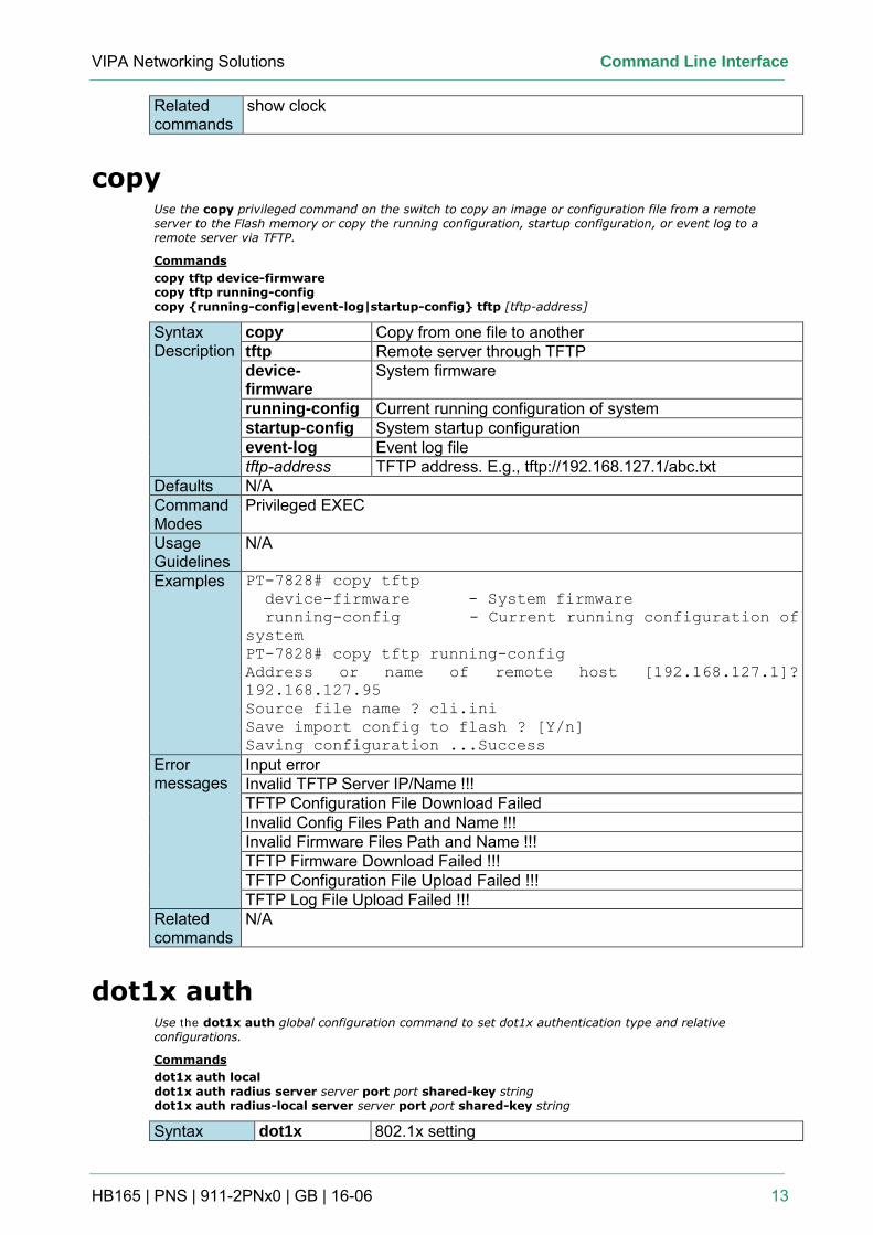
VIPA Networking Solutions Command Line Interface
HB165 | PNS | 911-2PNx0 | GB | 16-06 13
Related commands
show clock
copy Use the copy privileged command on the switch to copy an image or configuration file from a remote server to the Flash memory or copy the running configuration, startup configuration, or event log to a remote server via TFTP.
Commands
copy tftp device-firmware copy tftp running-config copy {running-config|event-log|startup-config} tftp [tftp-address]
Syntax Description
copy Copy from one file to another tftp Remote server through TFTP device-firmware
System firmware
running-config Current running configuration of system startup-config System startup configuration event-log Event log file tftp-address TFTP address. E.g., tftp://192.168.127.1/abc.txt
Defaults N/A Command Modes
Privileged EXEC
Usage Guidelines
N/A
Examples PT-7828# copy tftp
device-firmware - System firmware
running-config - Current running configuration of
system
PT-7828# copy tftp running-config
Address or name of remote host [192.168.127.1]?
192.168.127.95
Source file name ? cli.ini
Save import config to flash ? [Y/n]
Saving configuration ...Success
Error messages
Input error Invalid TFTP Server IP/Name !!! TFTP Configuration File Download Failed Invalid Config Files Path and Name !!! Invalid Firmware Files Path and Name !!! TFTP Firmware Download Failed !!! TFTP Configuration File Upload Failed !!! TFTP Log File Upload Failed !!!
Related commands
N/A
dot1x auth Use the dot1x auth global configuration command to set dot1x authentication type and relative configurations.
Commands
dot1x auth local
dot1x auth radius server server port port shared-key string dot1x auth radius-local server server port port shared-key string
Syntax dot1x 802.1x setting
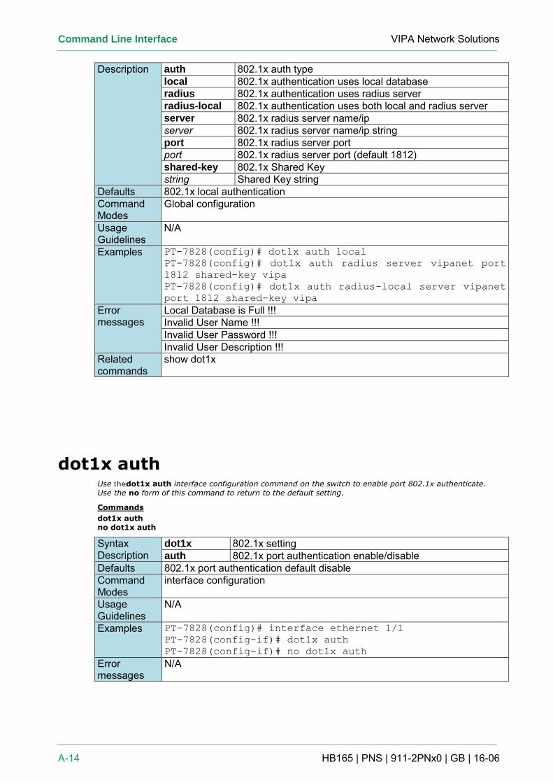
Command Line Interface VIPA Network Solutions
A-14 HB165 | PNS | 911-2PNx0 | GB | 16-06
Description auth 802.1x auth type local 802.1x authentication uses local database radius 802.1x authentication uses radius server radius-local 802.1x authentication uses both local and radius server server 802.1x radius server name/ip server 802.1x radius server name/ip string port 802.1x radius server port port 802.1x radius server port (default 1812) shared-key 802.1x Shared Key string Shared Key string
Defaults 802.1x local authentication Command Modes
Global configuration
Usage Guidelines
N/A
Examples PT-7828(config)# dot1x auth local
PT-7828(config)# dot1x auth radius server vipanet port
1812 shared-key vipa
PT-7828(config)# dot1x auth radius-local server vipanet
port 1812 shared-key vipa
Error messages
Local Database is Full !!! Invalid User Name !!! Invalid User Password !!! Invalid User Description !!!
Related commands
show dot1x
dot1x auth Use thedot1x auth interface configuration command on the switch to enable port 802.1x authenticate. Use the no form of this command to return to the default setting.
Commands
dot1x auth no dot1x auth
Syntax Description
dot1x 802.1x setting auth 802.1x port authentication enable/disable
Defaults 802.1x port authentication default disable Command Modes
interface configuration
Usage Guidelines
N/A
Examples PT-7828(config)# interface ethernet 1/1
PT-7828(config-if)# dot1x auth
PT-7828(config-if)# no dot1x auth
Error messages
N/A
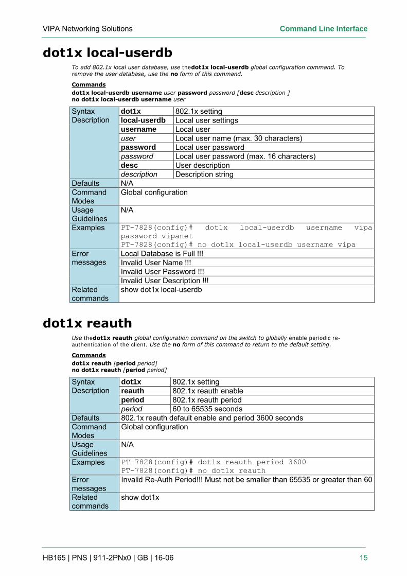
VIPA Networking Solutions Command Line Interface
HB165 | PNS | 911-2PNx0 | GB | 16-06 15
dot1x local-userdb To add 802.1x local user database, use thedot1x local-userdb global configuration command. To remove the user database, use the no form of this command.
Commands
dot1x local-userdb username user password password [desc description ] no dot1x local-userdb username user
Syntax Description
dot1x 802.1x setting local-userdb Local user settings username Local user user Local user name (max. 30 characters) password Local user password password Local user password (max. 16 characters) desc User description description Description string
Defaults N/A Command Modes
Global configuration
Usage Guidelines
N/A
Examples PT-7828(config)# dot1x local-userdb username vipa
password vipanet
PT-7828(config)# no dot1x local-userdb username vipa
Error messages
Local Database is Full !!! Invalid User Name !!! Invalid User Password !!! Invalid User Description !!!
Related commands
show dot1x local-userdb
dot1x reauth Use thedot1x reauth global configuration command on the switch to globally enable periodic re-authentication of the client. Use the no form of this command to return to the default setting.
Commands
dot1x reauth [period period] no dot1x reauth [period period]
Syntax Description
dot1x 802.1x setting reauth 802.1x reauth enable period 802.1x reauth period period 60 to 65535 seconds
Defaults 802.1x reauth default enable and period 3600 seconds Command Modes
Global configuration
Usage Guidelines
N/A
Examples PT-7828(config)# dot1x reauth period 3600
PT-7828(config)# no dot1x reauth
Error messages
Invalid Re-Auth Period!!! Must not be smaller than 65535 or greater than 60
Related commands
show dot1x
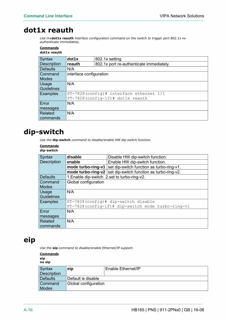
Command Line Interface VIPA Network Solutions
A-16 HB165 | PNS | 911-2PNx0 | GB | 16-06
dot1x reauth Use thedot1x reauth interface configuration command on the switch to trigger port 802.1x re-authenticate immediately.
Commands
dot1x reauth
Syntax Description
dot1x 802.1x setting reauth 802.1x port re-authenticate immediately
Defaults N/A Command Modes
interface configuration
Usage Guidelines
N/A
Examples PT-7828(config)# interface ethernet 1/1
PT-7828(config-if)# dot1x reauth
Error messages
N/A
Related commands
N/A
dip-switch Use the dip-switch command to disable/enable HW dip-switch function.
Commands
dip-switch
Syntax Description
disable Disable HW dip-switch function. enable Enable HW dip-switch function. mode turbo-ring-v1 set dip-switch function as turbo-ring-v1. mode turbo-ring-v2 set dip-switch function as turbo-ring-v2.
Defaults 1.Enable dip-switch. 2.set to turbo-ring-v2. Command Modes
Global configuration
Usage Guidelines
N/A
Examples PT-7828(config)# dip-switch disable
PT-7828(config-if)# dip-switch mode turbo-ring-v1
Error messages
N/A
Related commands
N/A
eip Use the eip command to disable/enable Ethernet/IP support.
Commands
eip no eip
Syntax Description
eip Enable Ethernet/IP
Defaults Default is disable Command Modes
Global configuration
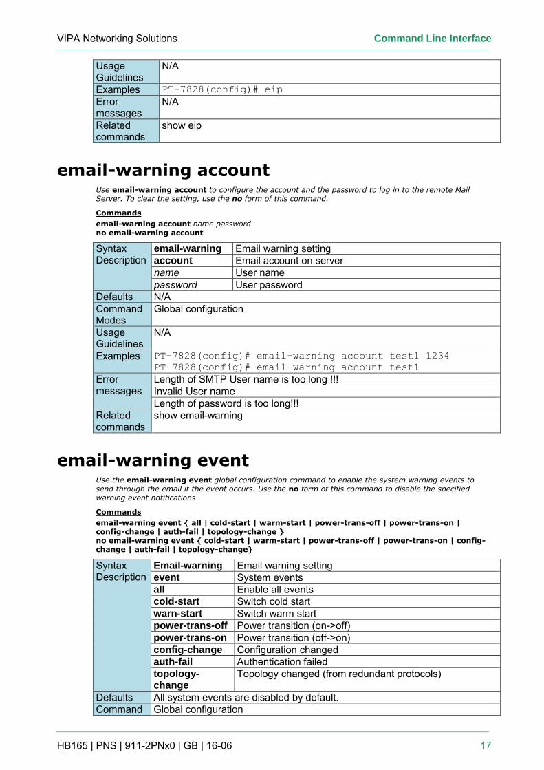
VIPA Networking Solutions Command Line Interface
HB165 | PNS | 911-2PNx0 | GB | 16-06 17
Usage Guidelines
N/A
Examples PT-7828(config)# eip
Error messages
N/A
Related commands
show eip
email-warning account Use email-warning account to configure the account and the password to log in to the remote Mail Server. To clear the setting, use the no form of this command.
Commands
email-warning account name password no email-warning account
Syntax Description
email-warning Email warning setting account Email account on server name User name password User password
Defaults N/A Command Modes
Global configuration
Usage Guidelines
N/A
Examples PT-7828(config)# email-warning account test1 1234
PT-7828(config)# email-warning account test1
Error messages
Length of SMTP User name is too long !!! Invalid User name Length of password is too long!!!
Related commands
show email-warning
email-warning event Use the email-warning event global configuration command to enable the system warning events to send through the email if the event occurs. Use the no form of this command to disable the specified warning event notifications.
Commands
email-warning event { all | cold-start | warm-start | power-trans-off | power-trans-on | config-change | auth-fail | topology-change } no email-warning event { cold-start | warm-start | power-trans-off | power-trans-on | config-change | auth-fail | topology-change}
Syntax Description
Email-warning Email warning setting event System events all Enable all events cold-start Switch cold start warn-start Switch warm start power-trans-off Power transition (on->off) power-trans-on Power transition (off->on) config-change Configuration changed auth-fail Authentication failed topology-change
Topology changed (from redundant protocols)
Defaults All system events are disabled by default. Command Global configuration
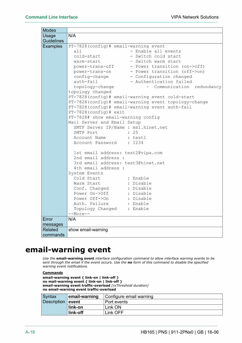
Command Line Interface VIPA Network Solutions
A-18 HB165 | PNS | 911-2PNx0 | GB | 16-06
Modes Usage Guidelines
N/A
Examples PT-7828(config)# email-warning event
all - Enable all events
cold-start - Switch cold start
warm-start - Switch warm start
power-trans-off - Power transition (on->off)
power-trans-on - Power transition (off->on)
config-change - Configuration changed
auth-fail - Authentication failed
topology-change - Communication redundancy
topology changed
PT-7828(config)# email-warning event cold-start
PT-7828(config)# email-warning event topology-change
PT-7828(config)# email-warning event auth-fail
PT-7828(config)# exit
PT-7828# show email-warning config
Mail Server and Email Setup
SMTP Server IP/Name : ms1.hinet.net
SMTP Port : 25
Account Name : test1
Account Password : 1234
1st email address: [email protected]
2nd email address :
3rd email address: [email protected]
4th email address :
System Events
Cold Start : Enable
Warm Start : Disable
Conf. Changed : Disable
Power On->Off : Disable
Power Off->On : Disable
Auth. Failure : Enable
Topology Changed : Enable
--More--
Error messages
N/A
Related commands
show email-warning
email-warning event Use the email-warning event interface configuration command to allow interface warning events to be sent through the email if the event occurs. Use the no form of this command to disable the specified warning event notifications.
Commands
email-warning event { link-on | link-off } no mail-warning event { link-on | link-off } email-warning event traffic-overload [rxThreshold duration] no email-warning event traffic-overload
Syntax Description
email-warning Configure email warning event Port events link-on Link ON link-off Link OFF
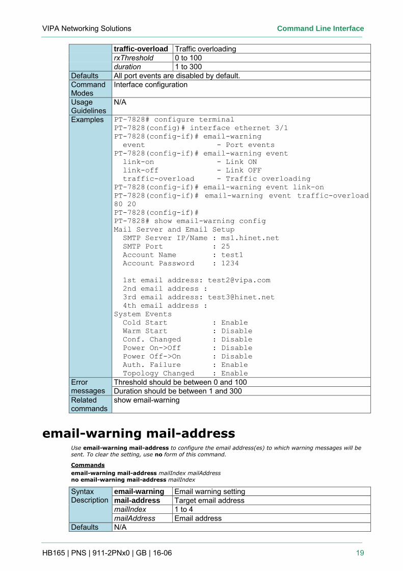
VIPA Networking Solutions Command Line Interface
HB165 | PNS | 911-2PNx0 | GB | 16-06 19
traffic-overload Traffic overloading rxThreshold 0 to 100 duration 1 to 300
Defaults All port events are disabled by default. Command Modes
Interface configuration
Usage Guidelines
N/A
Examples PT-7828# configure terminal
PT-7828(config)# interface ethernet 3/1
PT-7828(config-if)# email-warning
event - Port events
PT-7828(config-if)# email-warning event
link-on - Link ON
link-off - Link OFF
traffic-overload - Traffic overloading
PT-7828(config-if)# email-warning event link-on
PT-7828(config-if)# email-warning event traffic-overload
80 20
PT-7828(config-if)#
PT-7828# show email-warning config
Mail Server and Email Setup
SMTP Server IP/Name : ms1.hinet.net
SMTP Port : 25
Account Name : test1
Account Password : 1234
1st email address: [email protected]
2nd email address :
3rd email address: [email protected]
4th email address :
System Events
Cold Start : Enable
Warm Start : Disable
Conf. Changed : Disable
Power On->Off : Disable
Power Off->On : Disable
Auth. Failure : Enable
Topology Changed : Enable
Error messages
Threshold should be between 0 and 100 Duration should be between 1 and 300
Related commands
show email-warning
email-warning mail-address Use email-warning mail-address to configure the email address(es) to which warning messages will be sent. To clear the setting, use no form of this command.
Commands
email-warning mail-address mailIndex mailAddress no email-warning mail-address mailIndex
Syntax Description
email-warning Email warning setting mail-address Target email address mailIndex 1 to 4 mailAddress Email address
Defaults N/A
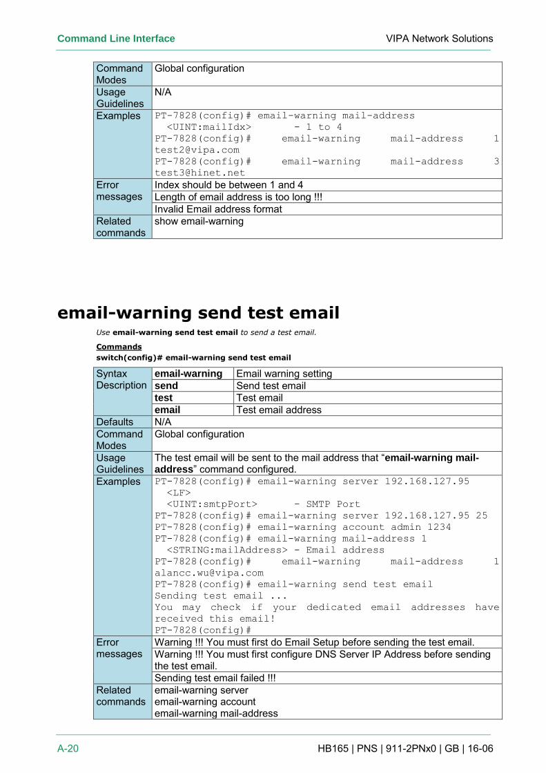
Command Line Interface VIPA Network Solutions
A-20 HB165 | PNS | 911-2PNx0 | GB | 16-06
Command Modes
Global configuration
Usage Guidelines
N/A
Examples PT-7828(config)# email-warning mail-address
<UINT:mailIdx> - 1 to 4
PT-7828(config)# email-warning mail-address 1
PT-7828(config)# email-warning mail-address 3
Error messages
Index should be between 1 and 4 Length of email address is too long !!! Invalid Email address format
Related commands
show email-warning
email-warning send test email Use email-warning send test email to send a test email.
Commands
switch(config)# email-warning send test email
Syntax Description
email-warning Email warning setting send Send test email test Test email email Test email address
Defaults N/A Command Modes
Global configuration
Usage Guidelines
The test email will be sent to the mail address that “email-warning mail-address” command configured.
Examples PT-7828(config)# email-warning server 192.168.127.95
<LF>
<UINT:smtpPort> - SMTP Port
PT-7828(config)# email-warning server 192.168.127.95 25
PT-7828(config)# email-warning account admin 1234
PT-7828(config)# email-warning mail-address 1
<STRING:mailAddress> - Email address
PT-7828(config)# email-warning mail-address 1
PT-7828(config)# email-warning send test email
Sending test email ...
You may check if your dedicated email addresses have
received this email!
PT-7828(config)#
Error messages
Warning !!! You must first do Email Setup before sending the test email. Warning !!! You must first configure DNS Server IP Address before sending the test email. Sending test email failed !!!
Related commands
email-warning server email-warning account email-warning mail-address
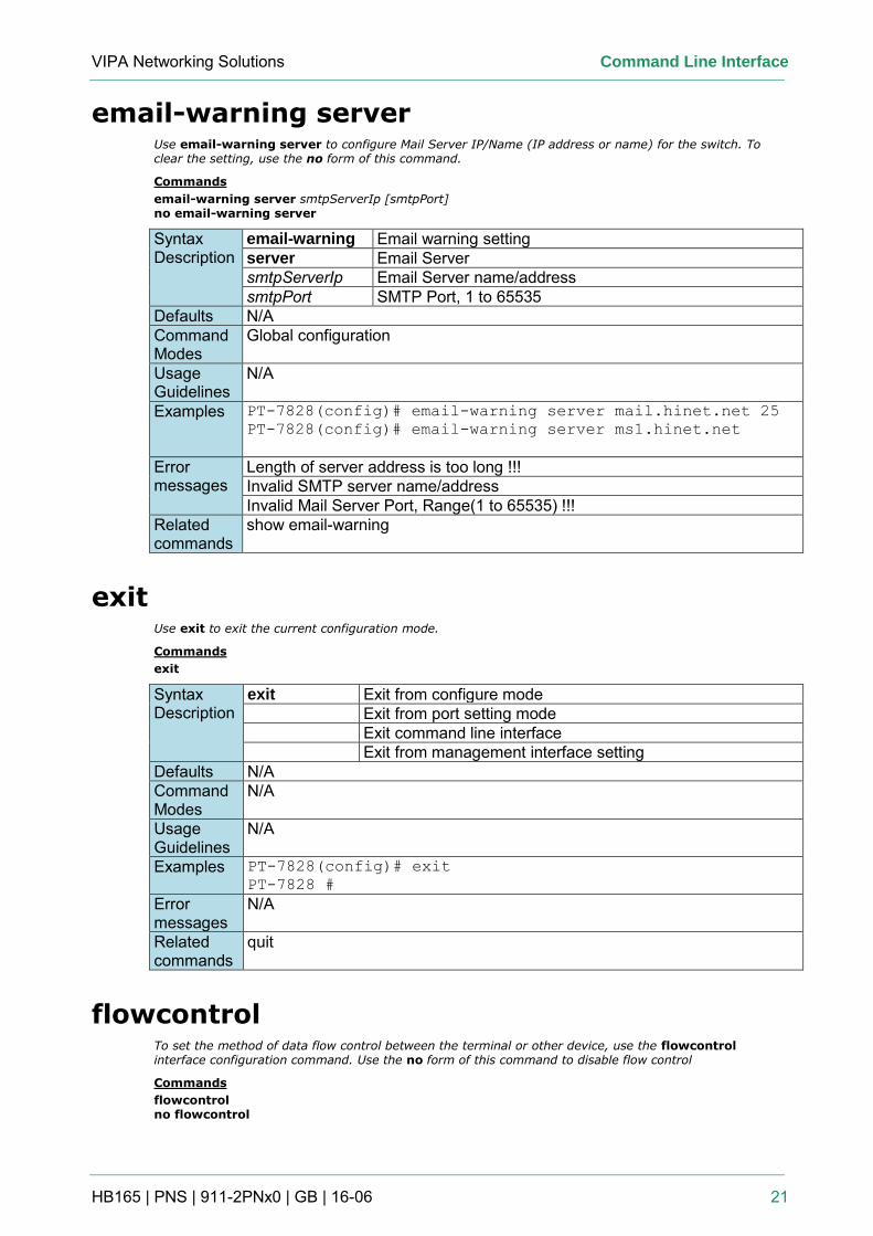
VIPA Networking Solutions Command Line Interface
HB165 | PNS | 911-2PNx0 | GB | 16-06 21
email-warning server Use email-warning server to configure Mail Server IP/Name (IP address or name) for the switch. To clear the setting, use the no form of this command.
Commands
email-warning server smtpServerIp [smtpPort] no email-warning server
Syntax Description
email-warning Email warning setting server Email Server smtpServerIp Email Server name/address smtpPort SMTP Port, 1 to 65535
Defaults N/A Command Modes
Global configuration
Usage Guidelines
N/A
Examples PT-7828(config)# email-warning server mail.hinet.net 25
PT-7828(config)# email-warning server ms1.hinet.net
Error messages
Length of server address is too long !!! Invalid SMTP server name/address Invalid Mail Server Port, Range(1 to 65535) !!!
Related commands
show email-warning
exit Use exit to exit the current configuration mode.
Commands
exit
Syntax Description
exit Exit from configure mode Exit from port setting mode Exit command line interface Exit from management interface setting
Defaults N/A Command Modes
N/A
Usage Guidelines
N/A
Examples PT-7828(config)# exit
PT-7828 #
Error messages
N/A
Related commands
quit
flowcontrol To set the method of data flow control between the terminal or other device, use the flowcontrol interface configuration command. Use the no form of this command to disable flow control
Commands
flowcontrol no flowcontrol
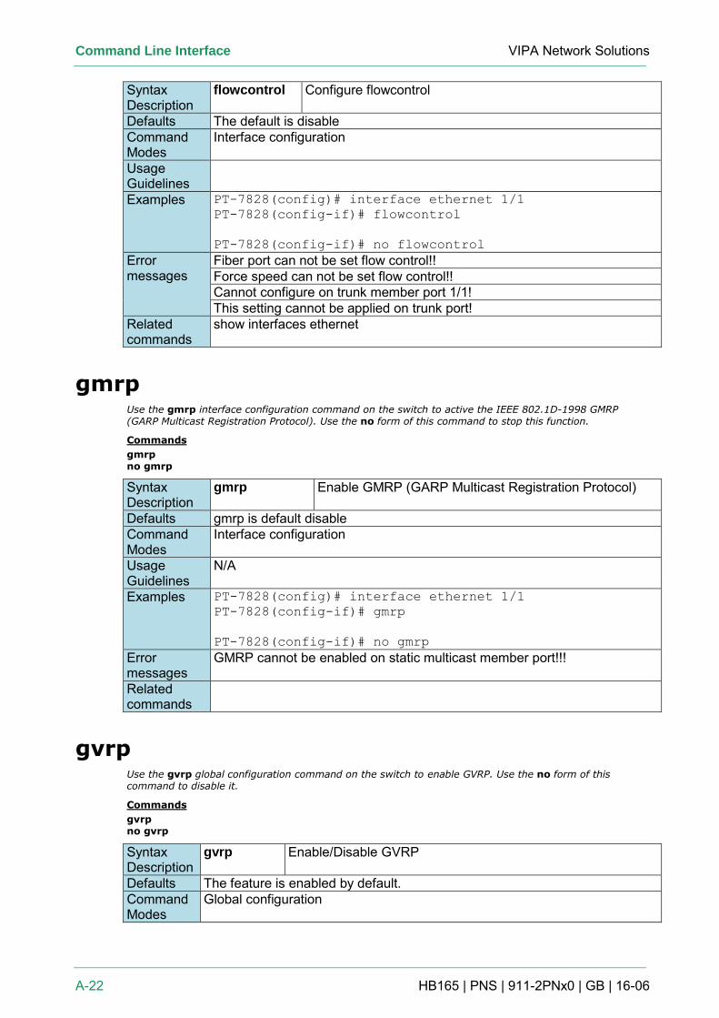
Command Line Interface VIPA Network Solutions
A-22 HB165 | PNS | 911-2PNx0 | GB | 16-06
Syntax Description
flowcontrol Configure flowcontrol
Defaults The default is disable Command Modes
Interface configuration
Usage Guidelines
Examples PT-7828(config)# interface ethernet 1/1
PT-7828(config-if)# flowcontrol
PT-7828(config-if)# no flowcontrol
Error messages
Fiber port can not be set flow control!! Force speed can not be set flow control!! Cannot configure on trunk member port 1/1! This setting cannot be applied on trunk port!
Related commands
show interfaces ethernet
gmrp Use the gmrp interface configuration command on the switch to active the IEEE 802.1D-1998 GMRP (GARP Multicast Registration Protocol). Use the no form of this command to stop this function.
Commands
gmrp no gmrp
Syntax Description
gmrp Enable GMRP (GARP Multicast Registration Protocol)
Defaults gmrp is default disable Command Modes
Interface configuration
Usage Guidelines
N/A
Examples PT-7828(config)# interface ethernet 1/1
PT-7828(config-if)# gmrp
PT-7828(config-if)# no gmrp
Error messages
GMRP cannot be enabled on static multicast member port!!!
Related commands
gvrp Use the gvrp global configuration command on the switch to enable GVRP. Use the no form of this command to disable it.
Commands
gvrp no gvrp
Syntax Description
gvrp Enable/Disable GVRP
Defaults The feature is enabled by default. Command Modes
Global configuration
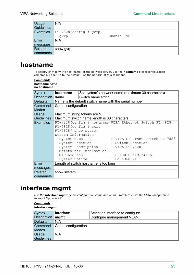
VIPA Networking Solutions Command Line Interface
HB165 | PNS | 911-2PNx0 | GB | 16-06 23
Usage Guidelines
N/A
Examples PT-7828(config)# gvrp
gvrp - Enable GVRP
Error messages
N/A
Related commands
show gvrp
hostname To specify or modify the host name for the network server, use the hostname global configuration command. To return to the default, use the no form of this command.
Commands
hostname name no hostname
Syntax Description
hostname Set system’s network name (maximum 30 characters) name Switch name string
Defaults Name is the default switch name with the serial number Command Modes
Global configuration
Usage Guidelines
Maximum string tokens are 5. Maximum switch name length is 30 characters.
Examples PT-7828(config)# hostname VIPA Ethernet Switch PT 7828
PT-7828(config)# exit
PT-7828# show system
System Information
System Name : VIPA Ethernet Switch PT 7828
System Location : Switch Location
System Description : VIPA PT-7828
Maintainer Information :
MAC Address : 00:90:E8:1D:24:36
System Uptime : 0d0h36m57s
Error messages
Length of switch hostname is too long
Related commands
show system
interface mgmt Use the interface mgmt global configuration command on the switch to enter the VLAN configuration mode of Mgmt-VLAN.
Commands
interface mgmt
Syntax Description
interface Select an interface to configure mgmt Configure management VLAN
Defaults N/A Command Modes
Global configuration
Usage Guidelines
N/A
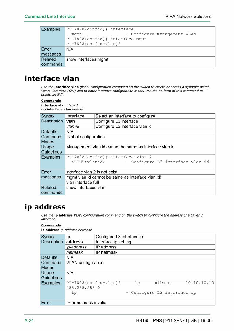
Command Line Interface VIPA Network Solutions
A-24 HB165 | PNS | 911-2PNx0 | GB | 16-06
Examples PT-7828(config)# interface
mgmt - Configure management VLAN
PT-7828(config)# interface mgmt
PT-7828(config-vlan)#
Error messages
N/A
Related commands
show interfaces mgmt
interface vlan Use the interface vlan global configuration command on the switch to create or access a dynamic switch virtual interface (SVI) and to enter interface configuration mode. Use the no form of this command to delete an SVI.
Commands
interface vlan vlan-id no interface vlan vlan-id
Syntax Description
interface Select an interface to configure vlan Configure L3 interface vlan-id Configure L3 interface vlan id
Defaults N/A Command Modes
Global configuration
Usage Guidelines
Management vlan id cannot be same as interface vlan id.
Examples PT-7828(config)# interface vlan 2
<UINT:vlanid> - Configure L3 interface vlan id
Error messages
interface vlan 2 is not exist mgmt vlan id cannot be same as interface vlan id!! vlan interface full
Related commands
show interfaces vlan
ip address Use the ip address VLAN configuration command on the switch to configure the address of a Layer 3 interface.
Commands
ip address ip-address netmask
Syntax Description
ip Configure L3 interface ip address Interface ip setting ip-address IP address netmask IP netmask
Defaults N/A Command Modes
VLAN configuration
Usage Guidelines
N/A
Examples PT-7828(config-vlan)# ip address 10.10.10.10
255.255.255.0
ip - Configure L3 interface ip
Error IP or netmask invalid
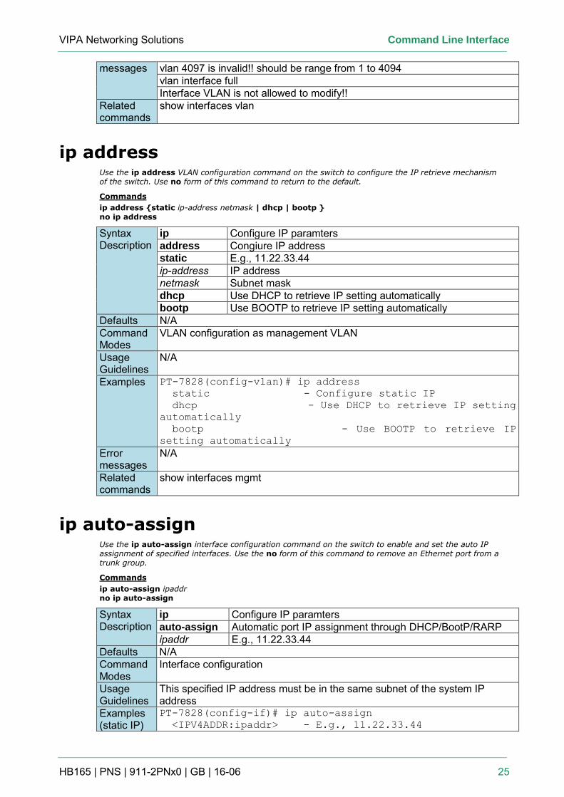
VIPA Networking Solutions Command Line Interface
HB165 | PNS | 911-2PNx0 | GB | 16-06 25
messages vlan 4097 is invalid!! should be range from 1 to 4094 vlan interface full Interface VLAN is not allowed to modify!!
Related commands
show interfaces vlan
ip address Use the ip address VLAN configuration command on the switch to configure the IP retrieve mechanism of the switch. Use no form of this command to return to the default.
Commands
ip address {static ip-address netmask | dhcp | bootp } no ip address
Syntax Description
ip Configure IP paramters address Congiure IP address static E.g., 11.22.33.44 ip-address IP address netmask Subnet mask dhcp Use DHCP to retrieve IP setting automatically bootp Use BOOTP to retrieve IP setting automatically
Defaults N/A Command Modes
VLAN configuration as management VLAN
Usage Guidelines
N/A
Examples PT-7828(config-vlan)# ip address
static - Configure static IP
dhcp - Use DHCP to retrieve IP setting
automatically
bootp - Use BOOTP to retrieve IP
setting automatically
Error messages
N/A
Related commands
show interfaces mgmt
ip auto-assign Use the ip auto-assign interface configuration command on the switch to enable and set the auto IP assignment of specified interfaces. Use the no form of this command to remove an Ethernet port from a trunk group.
Commands
ip auto-assign ipaddr no ip auto-assign
Syntax Description
ip Configure IP paramters auto-assign Automatic port IP assignment through DHCP/BootP/RARP ipaddr E.g., 11.22.33.44
Defaults N/A Command Modes
Interface configuration
Usage Guidelines
This specified IP address must be in the same subnet of the system IP address
Examples (static IP)
PT-7828(config-if)# ip auto-assign
<IPV4ADDR:ipaddr> - E.g., 11.22.33.44
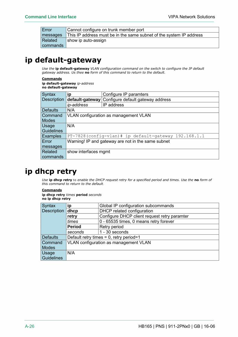
Command Line Interface VIPA Network Solutions
A-26 HB165 | PNS | 911-2PNx0 | GB | 16-06
Error messages
Cannot configure on trunk member port This IP address must be in the same subnet of the system IP address
Related commands
show ip auto-assign
ip default-gateway Use the ip default-gateway VLAN configuration command on the switch to configure the IP default gateway address. Us thee no form of this command to return to the default.
Commands
ip default-gateway ip-address no default-gateway
Syntax Description
ip Configure IP paramters default-gateway Configure default gateway address ip-address IP address
Defaults N/A Command Modes
VLAN configuration as management VLAN
Usage Guidelines
N/A
Examples PT-7828(config-vlan)# ip default-gateway 192.168.1.1
Error messages
Warning! IP and gateway are not in the same subnet
Related commands
show interfaces mgmt
ip dhcp retry Use ip dhcp retry to enable the DHCP request retry for a specified period and times. Use the no form of this command to return to the default.
Commands
ip dhcp retry times period seconds no ip dhcp retry
Syntax Description
ip Global IP configuration subcommands dhcp DHCP related configuration retry Configure DHCP client request retry paramter times 0 - 65535 times, 0 means retry forever Period Retry period seconds 1 - 30 seconds
Defaults Default retry times = 0, retry period=1 Command Modes
VLAN configuration as management VLAN
Usage Guidelines
N/A
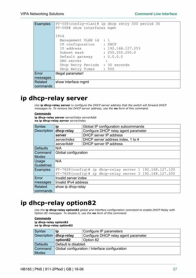
VIPA Networking Solutions Command Line Interface
HB165 | PNS | 911-2PNx0 | GB | 16-06 27
Examples PT-508(config-vlan)# ip dhcp retry 500 period 30
PT-508# show interfaces mgmt
IPv4
Management VLAN id : 1
IP configuration : DHCP
IP address : 192.168.127.253
Subnet mask : 255.255.255.0
Default gateway : 0.0.0.0
DNS server :
Dhcp Retry Periods : 30 seconds
Dhcp Retry Times : 500
Error messages
Illegal parameter!
Related commands
show interface mgmt
ip dhcp-relay server Use ip dhcp-relay server to configure the DHCP server address that the switch will forward DHCP messages to. To remove the DHCP server address, use the no form of this command.
Commands
ip dhcp-relay server serverIndex serverAddr no ip dhcp-relay server serverIndex
Syntax Description
ip Global IP configuration subcommands dhcp-relay Configure DHCP relay agent parameter server DHCP server IP address serverIndex DHCP server address index, 1 to 4 serverAddr DHCP server IP address
Defaults N/A Command Modes
Global configuration
Usage Guidelines
N/A
Examples PT-7828(config)# ip dhcp-relay server 1 192.168.127.100
PT-7828(config)# ip dhcp-relay server 3 192.168.127.200
Error messages
Invalid server index Invalid IPv4 address
Related commands
show ip dhcp-relay
ip dhcp-relay option82 Use the ip dhcp-relay option82 global and interface configuration command to enable DHCP Relay with Option 82 messages. To disable it, use the no form of this command.
Commands
ip dhcp-relay option82 no ip dhcp-relay option82
Syntax Description
Ip Configure IP parameters dhcp-relay Configure DHCP relay agent parameter option82 Option 82
Defaults Default is disabled. Command Modes
Global configuration / Interface configuration
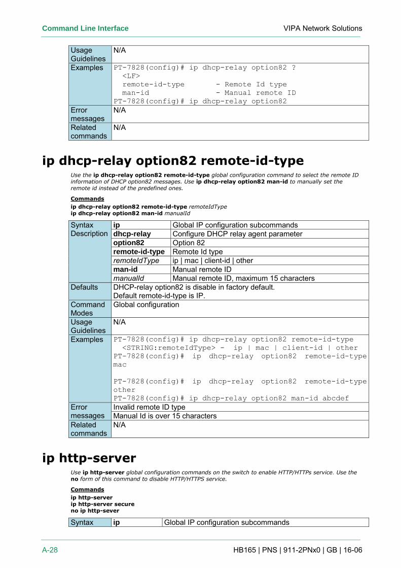
Command Line Interface VIPA Network Solutions
A-28 HB165 | PNS | 911-2PNx0 | GB | 16-06
Usage Guidelines
N/A
Examples PT-7828(config)# ip dhcp-relay option82 ?
<LF>
remote-id-type - Remote Id type
man-id - Manual remote ID
PT-7828(config)# ip dhcp-relay option82
Error messages
N/A
Related commands
N/A
ip dhcp-relay option82 remote-id-type Use the ip dhcp-relay option82 remote-id-type global configuration command to select the remote ID information of DHCP option82 messages. Use ip dhcp-relay option82 man-id to manually set the remote id instead of the predefined ones.
Commands
ip dhcp-relay option82 remote-id-type remoteIdType ip dhcp-relay option82 man-id manualId
Syntax Description
ip Global IP configuration subcommands dhcp-relay Configure DHCP relay agent parameter option82 Option 82 remote-id-type Remote Id type remoteIdType ip | mac | client-id | other man-id Manual remote ID manualId Manual remote ID, maximum 15 characters
Defaults DHCP-relay option82 is disable in factory default. Default remote-id-type is IP.
Command Modes
Global configuration
Usage Guidelines
N/A
Examples PT-7828(config)# ip dhcp-relay option82 remote-id-type
<STRING:remoteIdType> - ip | mac | client-id | other
PT-7828(config)# ip dhcp-relay option82 remote-id-type
mac
PT-7828(config)# ip dhcp-relay option82 remote-id-type
other
PT-7828(config)# ip dhcp-relay option82 man-id abcdef
Error messages
Invalid remote ID type Manual Id is over 15 characters
Related commands
N/A
ip http-server Use ip http-server global configuration commands on the switch to enable HTTP/HTTPs service. Use the no form of this command to disable HTTP/HTTPS service.
Commands
ip http-server ip http-server secure no ip http-sever
Syntax ip Global IP configuration subcommands
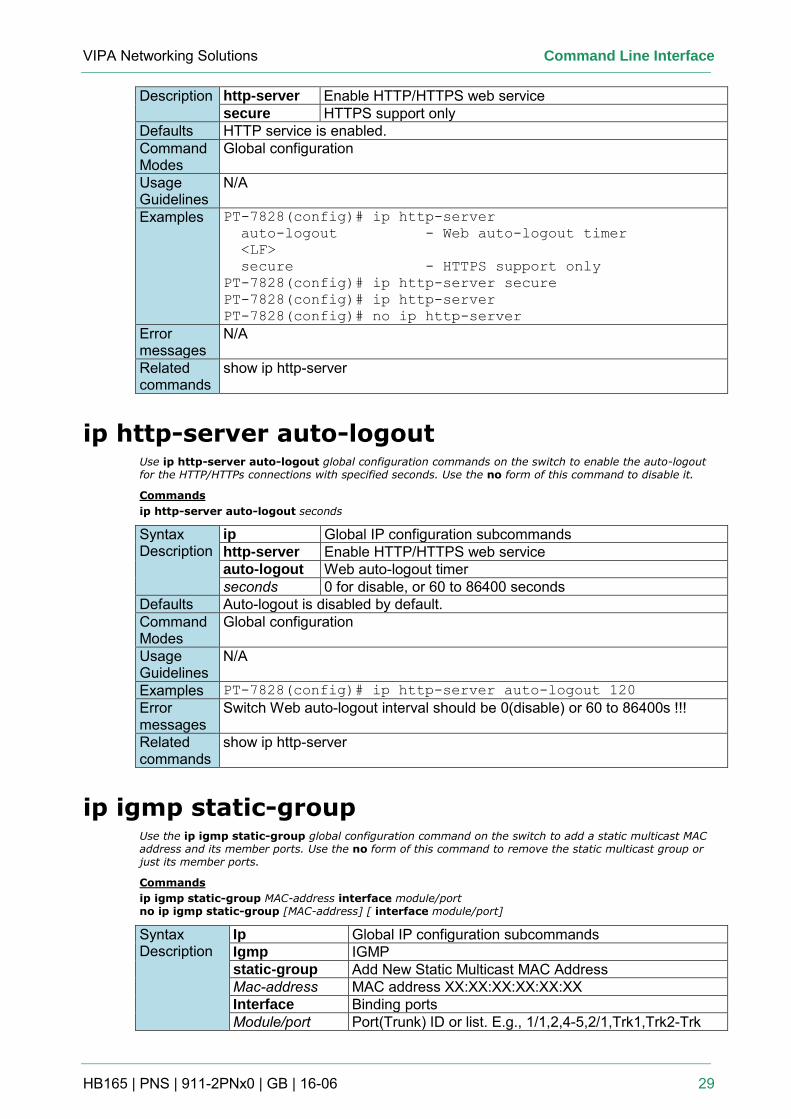
VIPA Networking Solutions Command Line Interface
HB165 | PNS | 911-2PNx0 | GB | 16-06 29
Description http-server Enable HTTP/HTTPS web service secure HTTPS support only
Defaults HTTP service is enabled. Command Modes
Global configuration
Usage Guidelines
N/A
Examples PT-7828(config)# ip http-server
auto-logout - Web auto-logout timer
<LF>
secure - HTTPS support only
PT-7828(config)# ip http-server secure
PT-7828(config)# ip http-server
PT-7828(config)# no ip http-server Error messages
N/A
Related commands
show ip http-server
ip http-server auto-logout Use ip http-server auto-logout global configuration commands on the switch to enable the auto-logout for the HTTP/HTTPs connections with specified seconds. Use the no form of this command to disable it.
Commands
ip http-server auto-logout seconds
Syntax Description
ip Global IP configuration subcommands http-server Enable HTTP/HTTPS web service auto-logout Web auto-logout timer seconds 0 for disable, or 60 to 86400 seconds
Defaults Auto-logout is disabled by default. Command Modes
Global configuration
Usage Guidelines
N/A
Examples PT-7828(config)# ip http-server auto-logout 120
Error messages
Switch Web auto-logout interval should be 0(disable) or 60 to 86400s !!!
Related commands
show ip http-server
ip igmp static-group Use the ip igmp static-group global configuration command on the switch to add a static multicast MAC address and its member ports. Use the no form of this command to remove the static multicast group or just its member ports.
Commands
ip igmp static-group MAC-address interface module/port no ip igmp static-group [MAC-address] [ interface module/port]
Syntax Description
Ip Global IP configuration subcommands Igmp IGMP static-group Add New Static Multicast MAC Address Mac-address MAC address XX:XX:XX:XX:XX:XX Interface Binding ports Module/port Port(Trunk) ID or list. E.g., 1/1,2,4-5,2/1,Trk1,Trk2-Trk
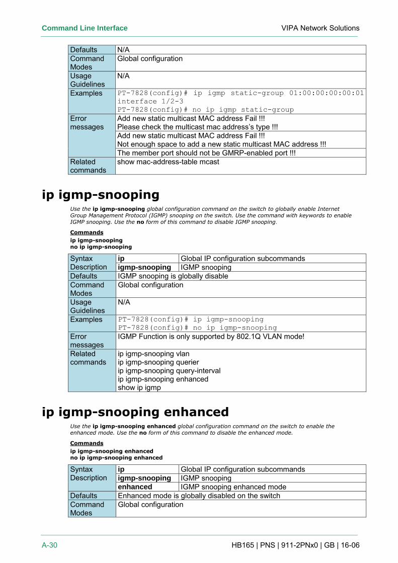
Command Line Interface VIPA Network Solutions
A-30 HB165 | PNS | 911-2PNx0 | GB | 16-06
Defaults N/A Command Modes
Global configuration
Usage Guidelines
N/A
Examples PT-7828(config)# ip igmp static-group 01:00:00:00:00:01
interface 1/2-3
PT-7828(config)# no ip igmp static-group
Error messages
Add new static multicast MAC address Fail !!! Please check the multicast mac address’s type !!! Add new static multicast MAC address Fail !!! Not enough space to add a new static multicast MAC address !!! The member port should not be GMRP-enabled port !!!
Related commands
show mac-address-table mcast
ip igmp-snooping Use the ip igmp-snooping global configuration command on the switch to globally enable Internet Group Management Protocol (IGMP) snooping on the switch. Use the command with keywords to enable IGMP snooping. Use the no form of this command to disable IGMP snooping.
Commands
ip igmp-snooping no ip igmp-snooping
Syntax Description
ip Global IP configuration subcommands igmp-snooping IGMP snooping
Defaults IGMP snooping is globally disable Command Modes
Global configuration
Usage Guidelines
N/A
Examples PT-7828(config)# ip igmp-snooping
PT-7828(config)# no ip igmp-snooping
Error messages
IGMP Function is only supported by 802.1Q VLAN mode!
Related commands
ip igmp-snooping vlan ip igmp-snooping querier ip igmp-snooping query-interval ip igmp-snooping enhanced show ip igmp
ip igmp-snooping enhanced Use the ip igmp-snooping enhanced global configuration command on the switch to enable the enhanced mode. Use the no form of this command to disable the enhanced mode.
Commands
ip igmp-snooping enhanced no ip igmp-snooping enhanced
Syntax Description
ip Global IP configuration subcommands igmp-snooping IGMP snooping enhanced IGMP snooping enhanced mode
Defaults Enhanced mode is globally disabled on the switch Command Modes
Global configuration
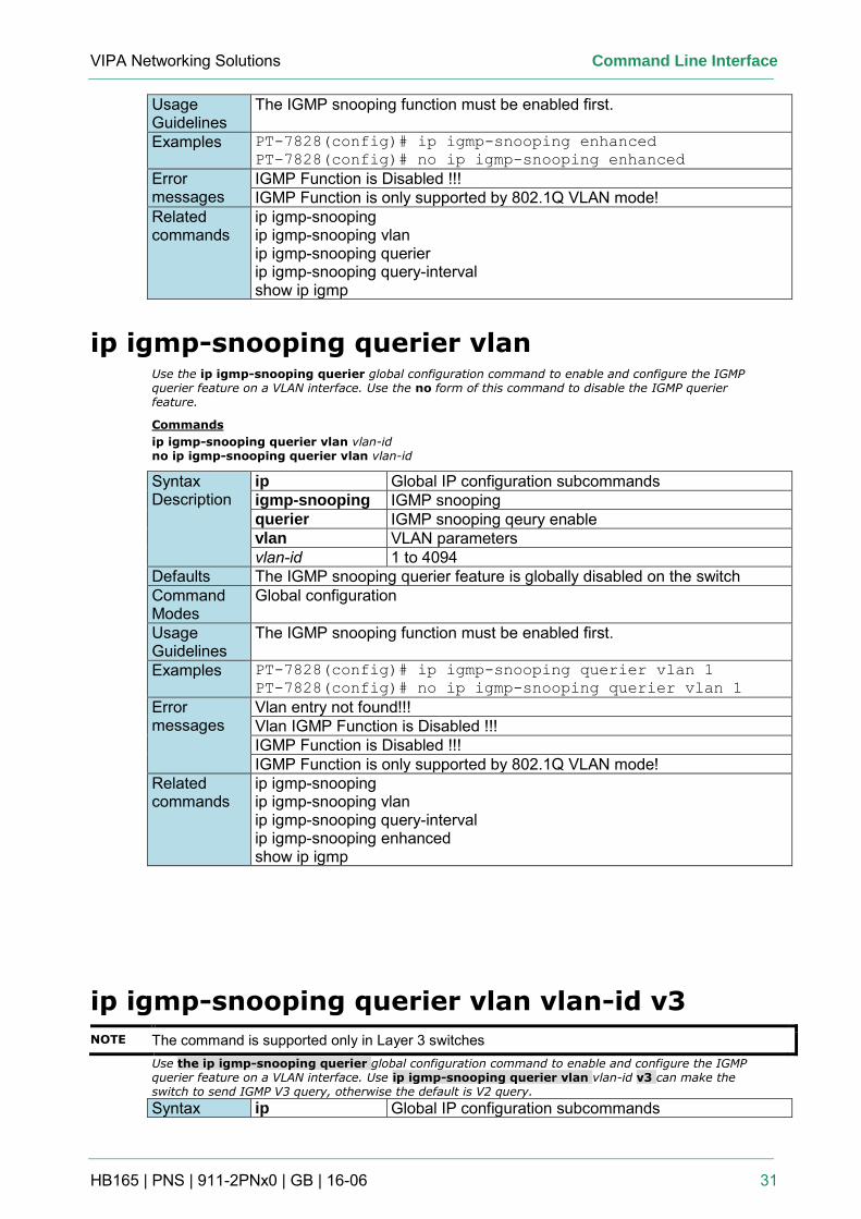
VIPA Networking Solutions Command Line Interface
HB165 | PNS | 911-2PNx0 | GB | 16-06 31
Usage Guidelines
The IGMP snooping function must be enabled first.
Examples PT-7828(config)# ip igmp-snooping enhanced
PT-7828(config)# no ip igmp-snooping enhanced
Error messages
IGMP Function is Disabled !!! IGMP Function is only supported by 802.1Q VLAN mode!
Related commands
ip igmp-snooping ip igmp-snooping vlan ip igmp-snooping querier ip igmp-snooping query-interval show ip igmp
ip igmp-snooping querier vlan Use the ip igmp-snooping querier global configuration command to enable and configure the IGMP querier feature on a VLAN interface. Use the no form of this command to disable the IGMP querier feature.
Commands
ip igmp-snooping querier vlan vlan-id no ip igmp-snooping querier vlan vlan-id
Syntax Description
ip Global IP configuration subcommands igmp-snooping IGMP snooping querier IGMP snooping qeury enable vlan VLAN parameters vlan-id 1 to 4094
Defaults The IGMP snooping querier feature is globally disabled on the switch Command Modes
Global configuration
Usage Guidelines
The IGMP snooping function must be enabled first.
Examples PT-7828(config)# ip igmp-snooping querier vlan 1
PT-7828(config)# no ip igmp-snooping querier vlan 1
Error messages
Vlan entry not found!!! Vlan IGMP Function is Disabled !!! IGMP Function is Disabled !!! IGMP Function is only supported by 802.1Q VLAN mode!
Related commands
ip igmp-snooping ip igmp-snooping vlan ip igmp-snooping query-interval ip igmp-snooping enhanced show ip igmp
ip igmp-snooping querier vlan vlan-id v3
NOTE The command is supported only in Layer 3 switches Use the ip igmp-snooping querier global configuration command to enable and configure the IGMP querier feature on a VLAN interface. Use ip igmp-snooping querier vlan vlan-id v3 can make the switch to send IGMP V3 query, otherwise the default is V2 query. Syntax ip Global IP configuration subcommands
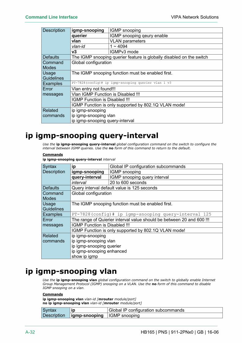
Command Line Interface VIPA Network Solutions
A-32 HB165 | PNS | 911-2PNx0 | GB | 16-06
Description igmp-snooping IGMP snooping querier IGMP snooping qeury enable vlan VLAN parameters vlan-id 1 ~ 4094 v3 IGMPv3 mode
Defaults The IGMP snooping querier feature is globally disabled on the switch Command Modes
Global configuration
Usage Guidelines
The IGMP snooping function must be enabled first.
Examples PT-7828(config)# ip igmp-snooping querier vlan 1 v3
Error messages
Vlan entry not found!!! Vlan IGMP Function is Disabled !!! IGMP Function is Disabled !!! IGMP Function is only supported by 802.1Q VLAN mode!
Related commands
ip igmp-snooping ip igmp-snooping vlan ip igmp-snooping query-interval
ip igmp-snooping query-interval Use the ip igmp-snooping query-interval global configuration command on the switch to configure the interval between IGMP queries. Use the no form of this command to return to the default.
Commands
ip igmp-snooping query-interval interval
Syntax Description
ip Global IP configuration subcommands igmp-snooping IGMP snooping query-interval IGMP snooping query interval interval 20 to 600 seconds
Defaults Query interval default value is 125 seconds Command Modes
Global configuration
Usage Guidelines
The IGMP snooping function must be enabled first.
Examples PT-7828(config)# ip igmp-snooping query-interval 125
Error messages
The range of Quierier interval value should be between 20 and 600 !!! IGMP Function is Disabled !!! IGMP Function is only supported by 802.1Q VLAN mode!
Related commands
ip igmp-snooping ip igmp-snooping vlan ip igmp-snooping querier ip igmp-snooping enhanced show ip igmp
ip igmp-snooping vlan Use the ip igmp-snooping vlan global configuration command on the switch to globally enable Internet Group Management Protocol (IGMP) snooping on a VLAN. Use the no form of this command to disable IGMP snooping on a vlan.
Commands
ip igmp-snooping vlan vlan-id [mrouter module/port] no ip igmp-snooping vlan vlan-id [mrouter module/port]
Syntax Description
ip Global IP configuration subcommands igmp-snooping IGMP snooping
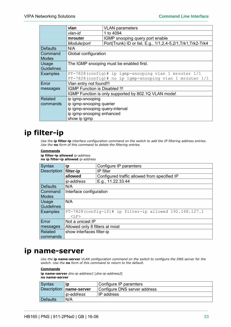
VIPA Networking Solutions Command Line Interface
HB165 | PNS | 911-2PNx0 | GB | 16-06 33
vlan VLAN parameters vlan-id 1 to 4094 mrouter IGMP snooping query port enable Module/port Port(Trunk) ID or list. E.g., 1/1,2,4-5,2/1,Trk1,Trk2-Trk4
Defaults N/A Command Modes
Global configuration
Usage Guidelines
The IGMP snooping must be enabled first.
Examples PT-7828(config)# ip igmp-snooping vlan 1 mrouter 1/1
PT-7828(config)# no ip igmp-snooping vlan 1 mrouter 1/1
Error messages
Vlan entry not found!!! IGMP Function is Disabled !!! IGMP Function is only supported by 802.1Q VLAN mode!
Related commands
ip igmp-snooping ip igmp-snooping querier ip igmp-snooping query-interval ip igmp-snooping enhanced show ip igmp
ip filter-ip Use the ip filter-ip interface configuration command on the switch to add the IP filtering address entries. Use the no form of this command to delete the filtering entries.
Commands
ip filter-ip allowed ip-address no ip filter-ip allowed ip-address
Syntax Description
ip Configure IP paramters filter-ip IP filter allowed Configured traffic allowed from specified IP ip-address E.g., 11.22.33.44
Defaults N/A Command Modes
Interface configuration
Usage Guidelines
N/A
Examples PT-7828(config-if)# ip filter-ip allowed 192.168.127.1
<LF>
Error messages
Not a unicast IP Allowed only 8 filters at most
Related commands
show interfaces filter-ip
ip name-server Use the ip name-server VLAN configuration command on the switch to configure the DNS server for the switch. Use the no form of this command to return to the default.
Commands
ip name-server dns-ip-address1 [dns-ip-address2] no name-server
Syntax Description
ip Configure IP paramters name-server Configure DNS server address ip-address IP address
Defaults N/A
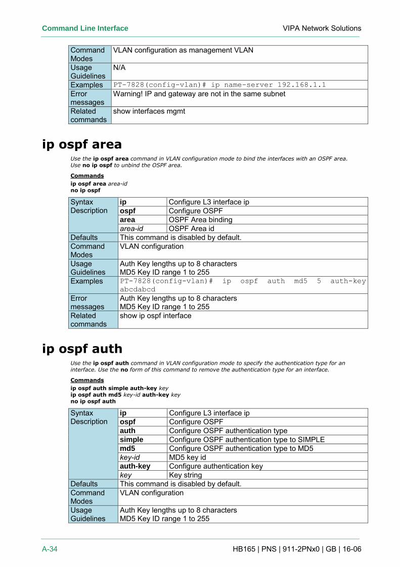
Command Line Interface VIPA Network Solutions
A-34 HB165 | PNS | 911-2PNx0 | GB | 16-06
Command Modes
VLAN configuration as management VLAN
Usage Guidelines
N/A
Examples PT-7828(config-vlan)# ip name-server 192.168.1.1
Error messages
Warning! IP and gateway are not in the same subnet
Related commands
show interfaces mgmt
ip ospf area Use the ip ospf area command in VLAN configuration mode to bind the interfaces with an OSPF area. Use no ip ospf to unbind the OSPF area.
Commands
ip ospf area area-id no ip ospf
Syntax Description
ip Configure L3 interface ip ospf Configure OSPF area OSPF Area binding area-id OSPF Area id
Defaults This command is disabled by default. Command Modes
VLAN configuration
Usage Guidelines
Auth Key lengths up to 8 characters MD5 Key ID range 1 to 255
Examples PT-7828(config-vlan)# ip ospf auth md5 5 auth-key
abcdabcd
Error messages
Auth Key lengths up to 8 characters MD5 Key ID range 1 to 255
Related commands
show ip ospf interface
ip ospf auth Use the ip ospf auth command in VLAN configuration mode to specify the authentication type for an interface. Use the no form of this command to remove the authentication type for an interface.
Commands
ip ospf auth simple auth-key key ip ospf auth md5 key-id auth-key key no ip ospf auth
Syntax Description
ip Configure L3 interface ip ospf Configure OSPF auth Configure OSPF authentication type simple Configure OSPF authentication type to SIMPLE md5 Configure OSPF authentication type to MD5 key-id MD5 key id auth-key Configure authentication key key Key string
Defaults This command is disabled by default. Command Modes
VLAN configuration
Usage Guidelines
Auth Key lengths up to 8 characters MD5 Key ID range 1 to 255
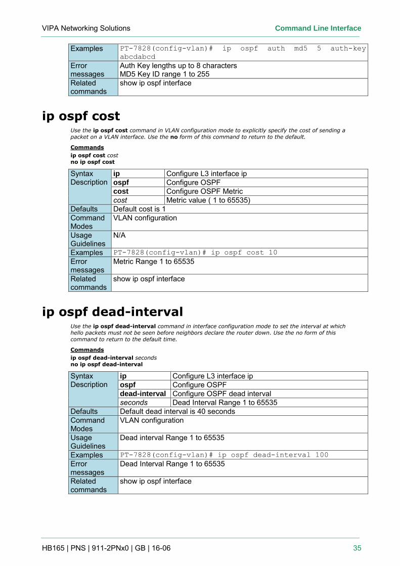
VIPA Networking Solutions Command Line Interface
HB165 | PNS | 911-2PNx0 | GB | 16-06 35
Examples PT-7828(config-vlan)# ip ospf auth md5 5 auth-key
abcdabcd
Error messages
Auth Key lengths up to 8 characters MD5 Key ID range 1 to 255
Related commands
show ip ospf interface
ip ospf cost Use the ip ospf cost command in VLAN configuration mode to explicitly specify the cost of sending a packet on a VLAN interface. Use the no form of this command to return to the default.
Commands
ip ospf cost cost no ip ospf cost
Syntax Description
ip Configure L3 interface ip ospf Configure OSPF cost Configure OSPF Metric cost Metric value ( 1 to 65535)
Defaults Default cost is 1 Command Modes
VLAN configuration
Usage Guidelines
N/A
Examples PT-7828(config-vlan)# ip ospf cost 10
Error messages
Metric Range 1 to 65535
Related commands
show ip ospf interface
ip ospf dead-interval Use the ip ospf dead-interval command in interface configuration mode to set the interval at which hello packets must not be seen before neighbors declare the router down. Use the no form of this command to return to the default time.
Commands
ip ospf dead-interval seconds no ip ospf dead-interval
Syntax Description
ip Configure L3 interface ip ospf Configure OSPF dead-interval Configure OSPF dead interval seconds Dead Interval Range 1 to 65535
Defaults Default dead interval is 40 seconds Command Modes
VLAN configuration
Usage Guidelines
Dead interval Range 1 to 65535
Examples PT-7828(config-vlan)# ip ospf dead-interval 100
Error messages
Dead Interval Range 1 to 65535
Related commands
show ip ospf interface
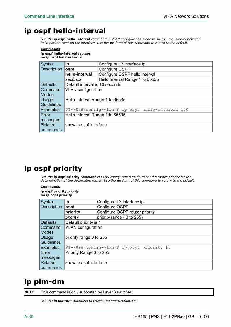
Command Line Interface VIPA Network Solutions
A-36 HB165 | PNS | 911-2PNx0 | GB | 16-06
ip ospf hello-interval Use the ip ospf hello-interval command in VLAN configuration mode to specify the interval between hello packets sent on the interface. Use the no form of this command to return to the default.
Commands
ip ospf hello-interval seconds no ip ospf hello-interval
Syntax Description
ip Configure L3 interface ip ospf Configure OSPF hello-interval Configure OSPF hello interval seconds Hello Interval Range 1 to 65535
Defaults Default interval is 10 seconds Command Modes
VLAN configuration
Usage Guidelines
Hello Interval Range 1 to 65535
Examples PT-7828(config-vlan)# ip ospf hello-interval 100
Error messages
Hello Interval Range 1 to 65535
Related commands
show ip ospf interface
ip ospf priority Use the ip ospf priority command in VLAN configuration mode to set the router priority for the determination of the designated router. Use the no form of this command to return to the default.
Commands
ip ospf priority priority no ip ospf priority
Syntax Description
ip Configure L3 interface ip ospf Configure OSPF priority Configure OSPF router priority priority priority range ( 0 to 255)
Defaults Default priority is 1 Command Modes
VLAN configuration
Usage Guidelines
priority range 0 to 255
Examples PT-7828(config-vlan)# ip ospf priority 10
Error messages
Priority Range 0 to 255
Related commands
show ip ospf interface
ip pim-dm
NOTE This command is only supported by Layer 3 switches.
Use the ip pim-dm command to enable the PIM-DM function.
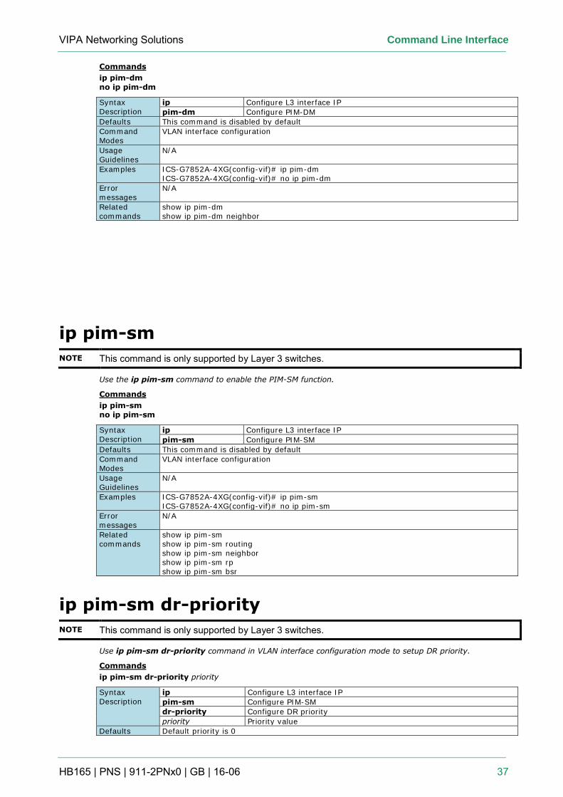
VIPA Networking Solutions Command Line Interface
HB165 | PNS | 911-2PNx0 | GB | 16-06 37
Commands
ip pim-dm no ip pim-dm
Syntax Description
ip Configure L3 interface IP
pim-dm Configure PIM-DM
Defaults This command is disabled by default
Command Modes
VLAN interface configuration
Usage Guidelines
N/A
Examples ICS-G7852A-4XG(config-vif)# ip pim-dm ICS-G7852A-4XG(config-vif)# no ip pim-dm
Error messages
N/A
Related commands
show ip pim-dm show ip pim-dm neighbor
ip pim-sm
NOTE This command is only supported by Layer 3 switches.
Use the ip pim-sm command to enable the PIM-SM function.
Commands
ip pim-sm no ip pim-sm
Syntax Description
ip Configure L3 interface IP
pim-sm Configure PIM-SM
Defaults This command is disabled by default
Command Modes
VLAN interface configuration
Usage Guidelines
N/A
Examples ICS-G7852A-4XG(config-vif)# ip pim-sm ICS-G7852A-4XG(config-vif)# no ip pim-sm
Error messages
N/A
Related commands
show ip pim-sm show ip pim-sm routing show ip pim-sm neighbor show ip pim-sm rp show ip pim-sm bsr
ip pim-sm dr-priority
NOTE This command is only supported by Layer 3 switches.
Use ip pim-sm dr-priority command in VLAN interface configuration mode to setup DR priority.
Commands
ip pim-sm dr-priority priority
Syntax Description
ip Configure L3 interface IP
pim-sm Configure PIM-SM
dr-priority Configure DR priority
priority Priority value
Defaults Default priority is 0
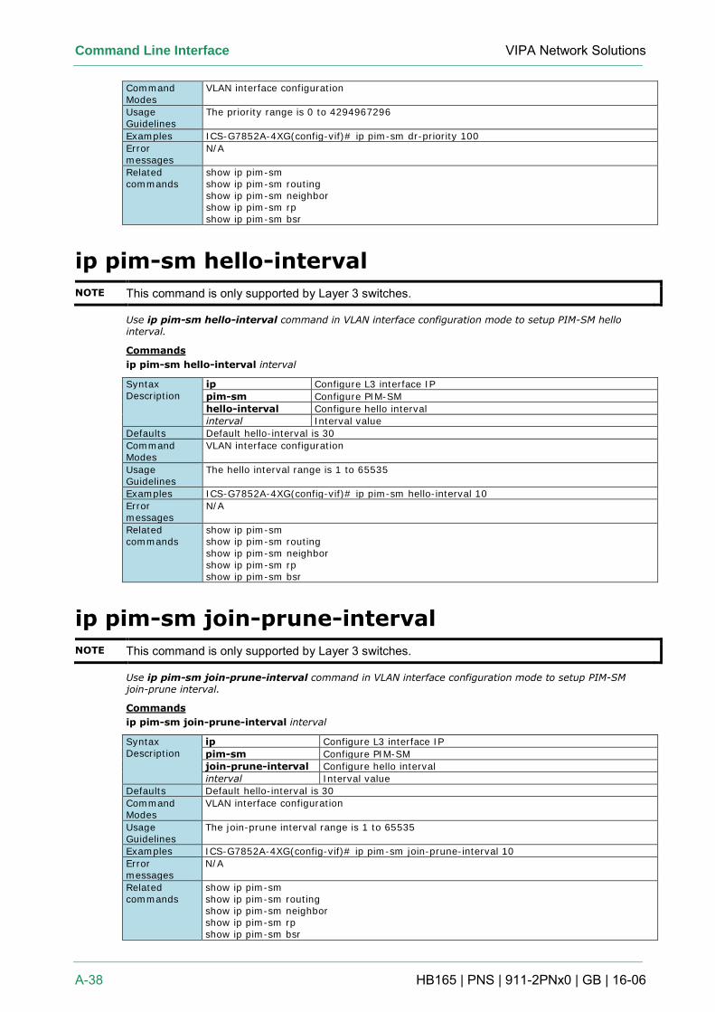
Command Line Interface VIPA Network Solutions
A-38 HB165 | PNS | 911-2PNx0 | GB | 16-06
Command Modes
VLAN interface configuration
Usage Guidelines
The priority range is 0 to 4294967296
Examples ICS-G7852A-4XG(config-vif)# ip pim-sm dr-priority 100
Error messages
N/A
Related commands
show ip pim-sm show ip pim-sm routing show ip pim-sm neighbor show ip pim-sm rp show ip pim-sm bsr
ip pim-sm hello-interval
NOTE This command is only supported by Layer 3 switches.
Use ip pim-sm hello-interval command in VLAN interface configuration mode to setup PIM-SM hello interval.
Commands
ip pim-sm hello-interval interval
Syntax Description
ip Configure L3 interface IP
pim-sm Configure PIM-SM
hello-interval Configure hello interval
interval Interval value
Defaults Default hello-interval is 30
Command Modes
VLAN interface configuration
Usage Guidelines
The hello interval range is 1 to 65535
Examples ICS-G7852A-4XG(config-vif)# ip pim-sm hello-interval 10
Error messages
N/A
Related commands
show ip pim-sm show ip pim-sm routing show ip pim-sm neighbor show ip pim-sm rp show ip pim-sm bsr
ip pim-sm join-prune-interval
NOTE This command is only supported by Layer 3 switches.
Use ip pim-sm join-prune-interval command in VLAN interface configuration mode to setup PIM-SM join-prune interval.
Commands
ip pim-sm join-prune-interval interval
Syntax Description
ip Configure L3 interface IP
pim-sm Configure PIM-SM
join-prune-interval Configure hello interval
interval Interval value
Defaults Default hello-interval is 30
Command Modes
VLAN interface configuration
Usage Guidelines
The join-prune interval range is 1 to 65535
Examples ICS-G7852A-4XG(config-vif)# ip pim-sm join-prune-interval 10
Error messages
N/A
Related commands
show ip pim-sm show ip pim-sm routing show ip pim-sm neighbor show ip pim-sm rp show ip pim-sm bsr
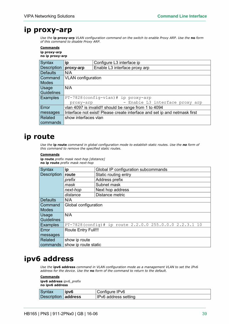
VIPA Networking Solutions Command Line Interface
HB165 | PNS | 911-2PNx0 | GB | 16-06 39
ip proxy-arp Use the ip proxy-arp VLAN configuration command on the switch to enable Proxy ARP. Use the no form of this command to disable Proxy ARP.
Commands
ip proxy-arp no ip proxy-arp
Syntax Description
ip Configure L3 interface ip proxy-arp Enable L3 interface proxy arp
Defaults N/A Command Modes
VLAN configuration
Usage Guidelines
N/A
Examples PT-7828(config-vlan)# ip proxy-arp
proxy-arp - Enable L3 interface proxy arp
Error messages
vlan 4097 is invalid!! should be range from 1 to 4094 Interface not exist! Please create interface and set ip and netmask first
Related commands
show interfaces vlan
ip route Use the ip route command in global configuration mode to establish static routes. Use the no form of this command to remove the specified static routes.
Commands
ip route prefix mask next-hop [distance] no ip route prefix mask next-hop
Syntax Description
ip Global IP configuration subcommands route Static routing entry prefix Address prefix mask Subnet mask next-hop Next hop address distance Distance metric
Defaults N/A Command Modes
Global configuration
Usage Guidelines
N/A
Examples PT-7828(config)# ip route 2.2.0.0 255.0.0.0 2.2.3.1 10
Error messages
Route Entry Full!!!
Related commands
show ip route show ip route static
ipv6 address Use the ipv6 address command in VLAN configuration mode as a management VLAN to set the IPv6 address for the device. Use the no form of the command to return to the default.
Commands
ipv6 address ipv6_prefix no ipv6 address
Syntax Description
ipv6 Configure IPv6 address IPv6 address setting
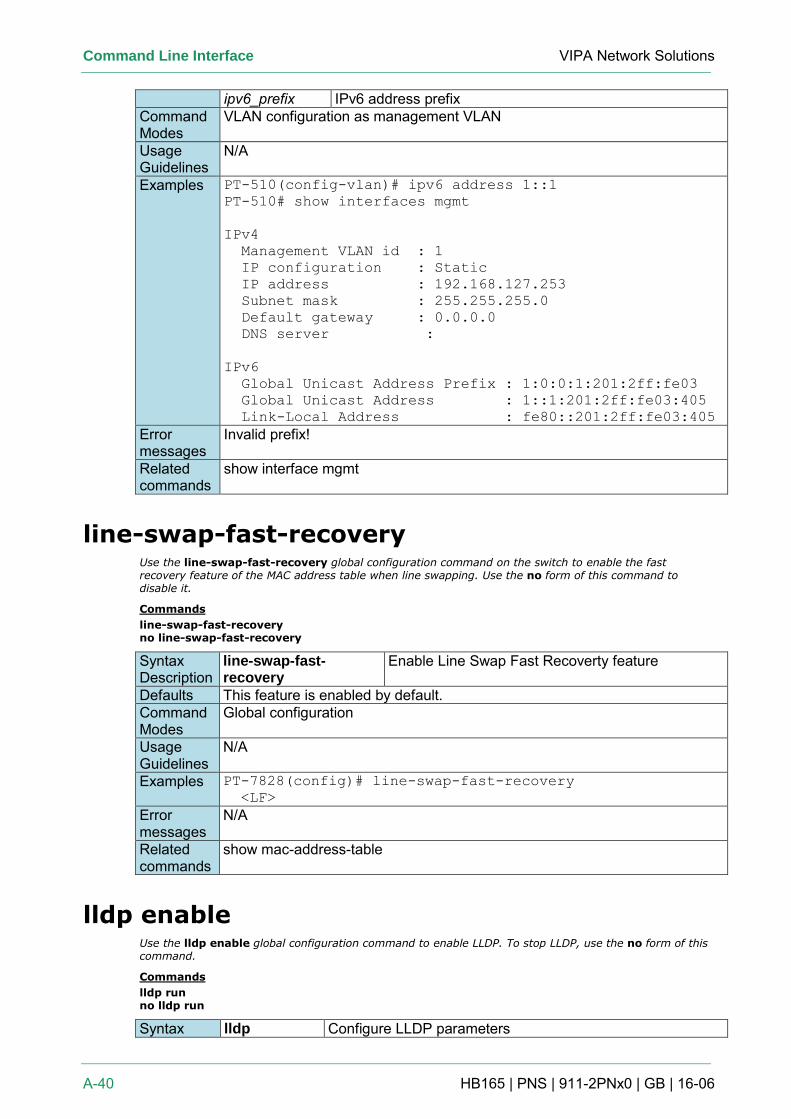
Command Line Interface VIPA Network Solutions
A-40 HB165 | PNS | 911-2PNx0 | GB | 16-06
ipv6_prefix IPv6 address prefix Command Modes
VLAN configuration as management VLAN
Usage Guidelines
N/A
Examples PT-510(config-vlan)# ipv6 address 1::1
PT-510# show interfaces mgmt
IPv4
Management VLAN id : 1
IP configuration : Static
IP address : 192.168.127.253
Subnet mask : 255.255.255.0
Default gateway : 0.0.0.0
DNS server :
IPv6
Global Unicast Address Prefix : 1:0:0:1:201:2ff:fe03
Global Unicast Address : 1::1:201:2ff:fe03:405
Link-Local Address : fe80::201:2ff:fe03:405
Error messages
Invalid prefix!
Related commands
show interface mgmt
line-swap-fast-recovery Use the line-swap-fast-recovery global configuration command on the switch to enable the fast recovery feature of the MAC address table when line swapping. Use the no form of this command to disable it.
Commands
line-swap-fast-recovery no line-swap-fast-recovery
Syntax Description
line-swap-fast-recovery
Enable Line Swap Fast Recoverty feature
Defaults This feature is enabled by default. Command Modes
Global configuration
Usage Guidelines
N/A
Examples PT-7828(config)# line-swap-fast-recovery
<LF>
Error messages
N/A
Related commands
show mac-address-table
lldp enable Use the lldp enable global configuration command to enable LLDP. To stop LLDP, use the no form of this command.
Commands
lldp run no lldp run
Syntax lldp Configure LLDP parameters
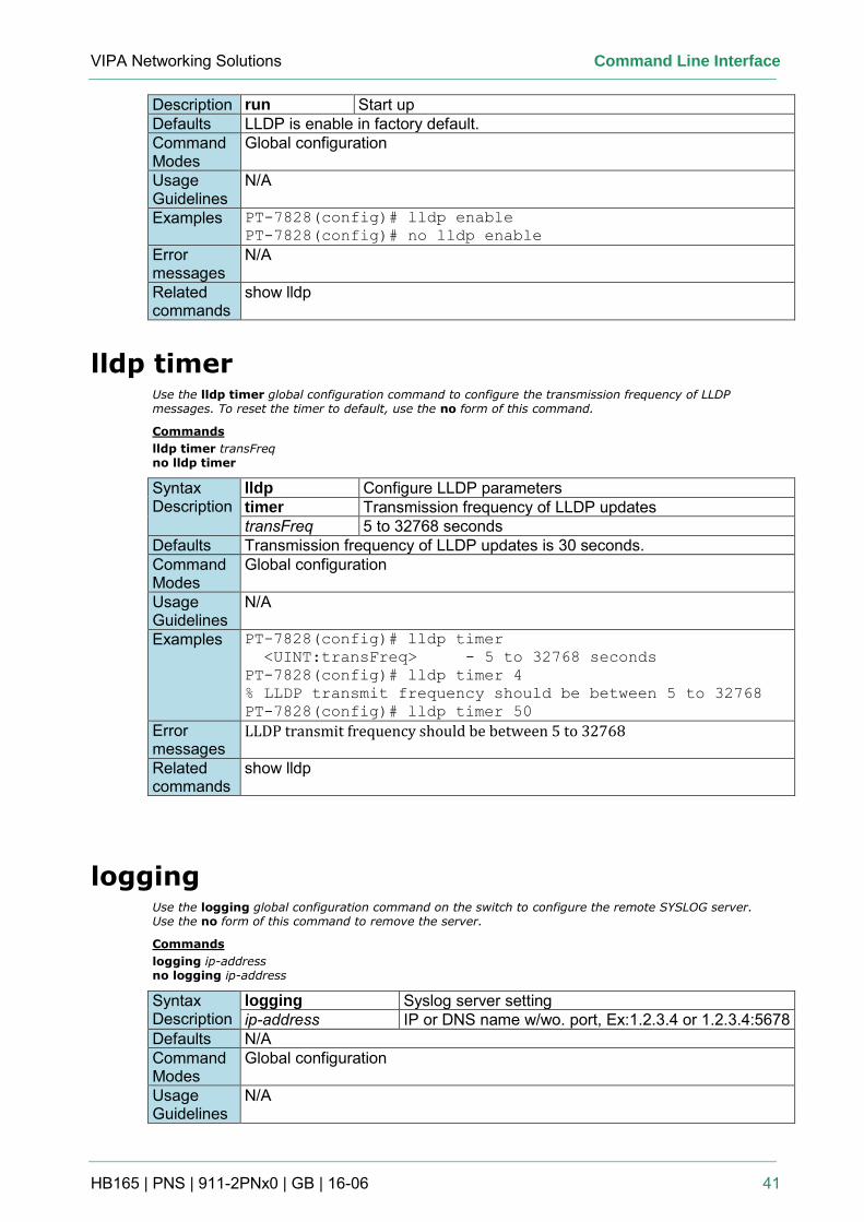
VIPA Networking Solutions Command Line Interface
HB165 | PNS | 911-2PNx0 | GB | 16-06 41
Description run Start up Defaults LLDP is enable in factory default. Command Modes
Global configuration
Usage Guidelines
N/A
Examples PT-7828(config)# lldp enable
PT-7828(config)# no lldp enable
Error messages
N/A
Related commands
show lldp
lldp timer Use the lldp timer global configuration command to configure the transmission frequency of LLDP messages. To reset the timer to default, use the no form of this command.
Commands
lldp timer transFreq no lldp timer
Syntax Description
lldp Configure LLDP parameters timer Transmission frequency of LLDP updates transFreq 5 to 32768 seconds
Defaults Transmission frequency of LLDP updates is 30 seconds. Command Modes
Global configuration
Usage Guidelines
N/A
Examples PT-7828(config)# lldp timer
<UINT:transFreq> - 5 to 32768 seconds
PT-7828(config)# lldp timer 4
% LLDP transmit frequency should be between 5 to 32768
PT-7828(config)# lldp timer 50
Error messages
LLDP transmit frequency should be between 5 to 32768
Related commands
show lldp
logging Use the logging global configuration command on the switch to configure the remote SYSLOG server. Use the no form of this command to remove the server.
Commands
logging ip-address no logging ip-address
Syntax Description
logging Syslog server setting ip-address IP or DNS name w/wo. port, Ex:1.2.3.4 or 1.2.3.4:5678
Defaults N/A Command Modes
Global configuration
Usage Guidelines
N/A
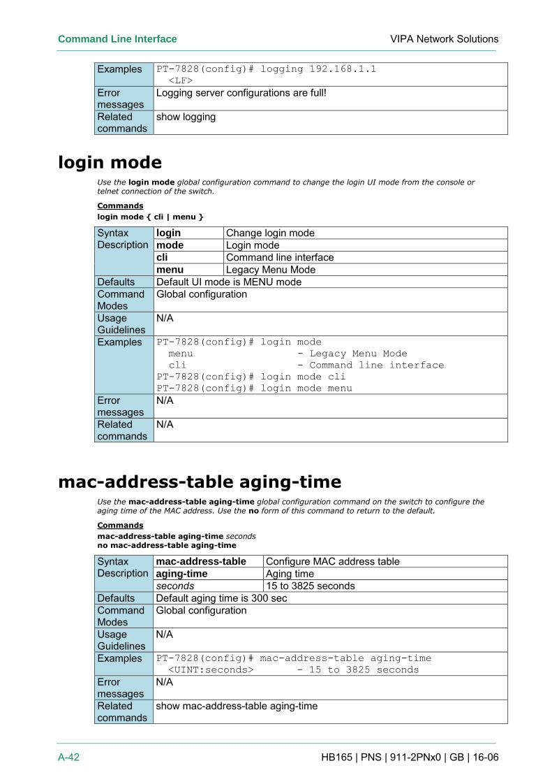
Command Line Interface VIPA Network Solutions
A-42 HB165 | PNS | 911-2PNx0 | GB | 16-06
Examples PT-7828(config)# logging 192.168.1.1
<LF>
Error messages
Logging server configurations are full!
Related commands
show logging
login mode Use the login mode global configuration command to change the login UI mode from the console or telnet connection of the switch.
Commands
login mode { cli | menu }
Syntax Description
login Change login mode mode Login mode cli Command line interface menu Legacy Menu Mode
Defaults Default UI mode is MENU mode Command Modes
Global configuration
Usage Guidelines
N/A
Examples PT-7828(config)# login mode
menu - Legacy Menu Mode
cli - Command line interface
PT-7828(config)# login mode cli
PT-7828(config)# login mode menu
Error messages
N/A
Related commands
N/A
mac-address-table aging-time Use the mac-address-table aging-time global configuration command on the switch to configure the aging time of the MAC address. Use the no form of this command to return to the default.
Commands
mac-address-table aging-time seconds no mac-address-table aging-time
Syntax Description
mac-address-table Configure MAC address table aging-time Aging time seconds 15 to 3825 seconds
Defaults Default aging time is 300 sec Command Modes
Global configuration
Usage Guidelines
N/A
Examples PT-7828(config)# mac-address-table aging-time
<UINT:seconds> - 15 to 3825 seconds
Error messages
N/A
Related commands
show mac-address-table aging-time
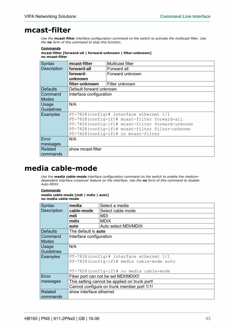
VIPA Networking Solutions Command Line Interface
HB165 | PNS | 911-2PNx0 | GB | 16-06 43
mcast-filter Use the mcast-filter interface configuration command on the switch to activate the multicast filter. Use the no form of this command to stop this function.
Commands
mcast-filter [forward-all | forward-unknown | filter-unknown] no mcast-filter
Syntax Description
mcast-filter Multicast filter forward-all Forward all forward-unknown
Forward unknown
filter-unknown Filter unknown Defaults Default forward unknown Command Modes
Interface configuration
Usage Guidelines
N/A
Examples PT-7828(config)# interface ethernet 1/1
PT-7828(config-if)# mcast-filter forward-all
PT-7828(config-if)# mcast-filter forward-unknown
PT-7828(config-if)# mcast-filter filter-unknown
PT-7828(config-if)# no mcast-filter
Error messages
N/A
Related commands
show mcast-filter
media cable-mode Use the media cable-mode interface configuration command on the switch to enable the medium-dependent interface crossover feature on the interface. Use the no form of this command to disable Auto-MDIX.
Commands
media cable-mode [mdi | mdix | auto] no media cable-mode
Syntax Description
media Select a media cable-mode Select cable mode mdi MDI mdix MDIX auto Auto select MDI/MDIX
Defaults The default is auto Command Modes
Interface configuration
Usage Guidelines
N/A
Examples PT-7828(config)# interface ethernet 1/1
PT-7828(config-if)# media cable-mode auto
PT-7828(config-if)# no media cable-mode
Error messages
Fiber port can not be set MDI/MDIX!! This setting cannot be applied on trunk port! Cannot configure on trunk member port 1/1!
Related commands
show interface ethernet
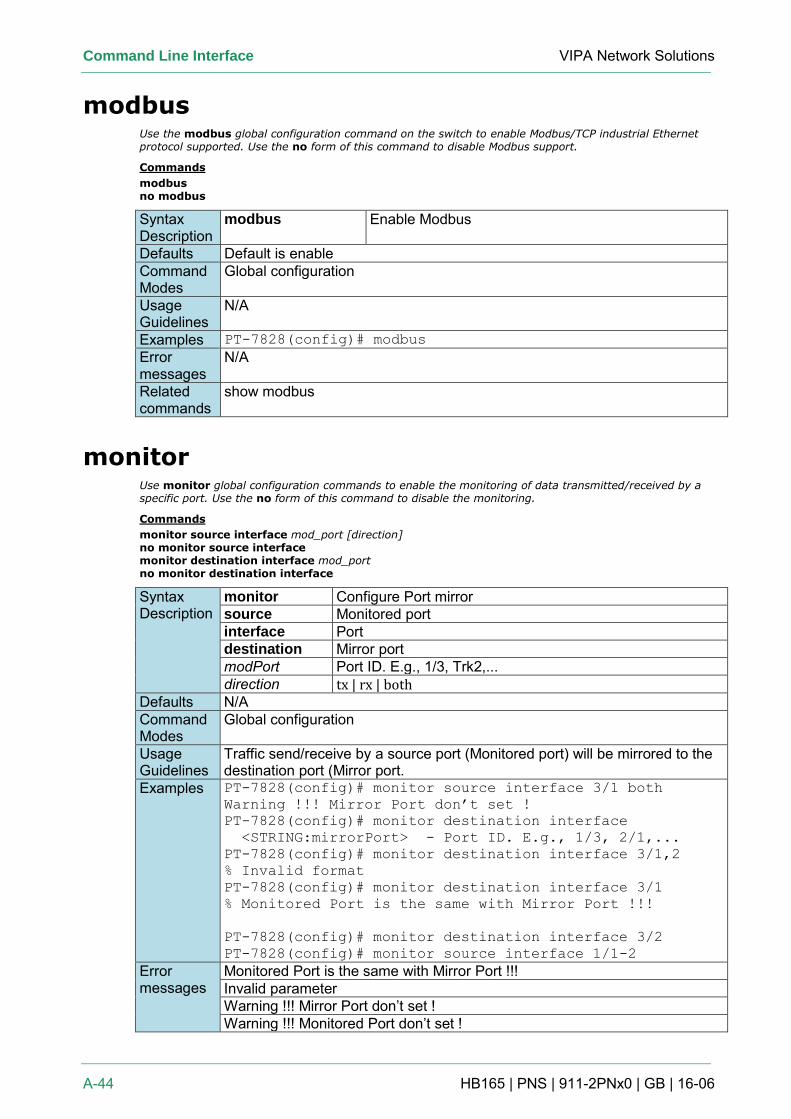
Command Line Interface VIPA Network Solutions
A-44 HB165 | PNS | 911-2PNx0 | GB | 16-06
modbus Use the modbus global configuration command on the switch to enable Modbus/TCP industrial Ethernet protocol supported. Use the no form of this command to disable Modbus support.
Commands
modbus no modbus
Syntax Description
modbus Enable Modbus
Defaults Default is enable Command Modes
Global configuration
Usage Guidelines
N/A
Examples PT-7828(config)# modbus
Error messages
N/A
Related commands
show modbus
monitor Use monitor global configuration commands to enable the monitoring of data transmitted/received by a specific port. Use the no form of this command to disable the monitoring.
Commands
monitor source interface mod_port [direction] no monitor source interface monitor destination interface mod_port no monitor destination interface
Syntax Description
monitor Configure Port mirror source Monitored port interface Port destination Mirror port modPort Port ID. E.g., 1/3, Trk2,... direction tx | rx | both
Defaults N/A Command Modes
Global configuration
Usage Guidelines
Traffic send/receive by a source port (Monitored port) will be mirrored to the destination port (Mirror port.
Examples PT-7828(config)# monitor source interface 3/1 both
Warning !!! Mirror Port don’t set !
PT-7828(config)# monitor destination interface
<STRING:mirrorPort> - Port ID. E.g., 1/3, 2/1,...
PT-7828(config)# monitor destination interface 3/1,2
% Invalid format
PT-7828(config)# monitor destination interface 3/1
% Monitored Port is the same with Mirror Port !!!
PT-7828(config)# monitor destination interface 3/2
PT-7828(config)# monitor source interface 1/1-2
Error messages
Monitored Port is the same with Mirror Port !!! Invalid parameter Warning !!! Mirror Port don’t set ! Warning !!! Monitored Port don’t set !
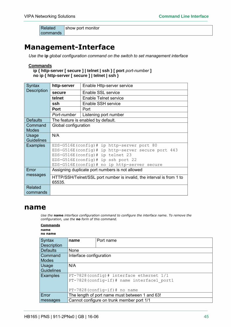
VIPA Networking Solutions Command Line Interface
HB165 | PNS | 911-2PNx0 | GB | 16-06 45
Related commands
show port monitor
Management-Interface Use the ip global configuration command on the switch to set management interface Commands
ip { http-server [ secure ] | telnet | ssh } [ port port-number ] no ip { http-server [ secure ] | telnet | ssh }
Syntax Description
http-server Enable Http-server service secure Enable SSL service telnet Enable Telnet service ssh Enable SSH service Port Port Port-number Listening port number
Defaults The feature is enabled by default. Command Modes
Global configuration
Usage Guidelines
N/A
Examples EDS-G516E(config)# ip http-server port 80
EDS-G516E(config)# ip http-server secure port 443
EDS-G516E(config)# ip telnet 23
EDS-G516E(config)# ip ssh port 22
EDS-G516E(config)# no ip http-server secure
Error messages
Assigning duplicate port numbers is not allowed
HTTP/SSH/Telnet/SSL port number is invalid, the interval is from 1 to 65535.
Related commands
name Use the name interface configuration command to configure the interface name. To remove the configuration, use the no form of this command.
Commands
name no name
Syntax Description
name Port name
Defaults None Command Modes
Interface configuration
Usage Guidelines
N/A
Examples PT-7828(config)# interface ethernet 1/1
PT-7828(config-if)# name interface1_port1
PT-7828(config-if)# no name
Error messages
The length of port name must between 1 and 63! Cannot configure on trunk member port 1/1
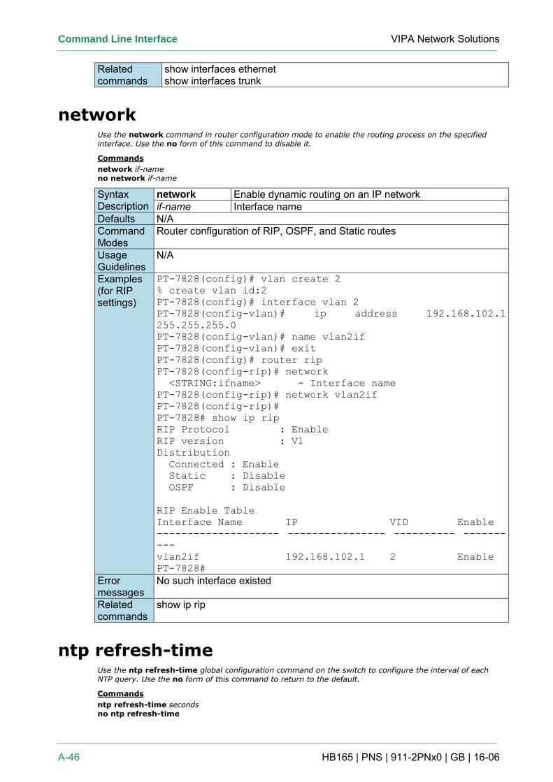
Command Line Interface VIPA Network Solutions
A-46 HB165 | PNS | 911-2PNx0 | GB | 16-06
Related commands
show interfaces ethernet show interfaces trunk
network Use the network command in router configuration mode to enable the routing process on the specified interface. Use the no form of this command to disable it.
Commands
network if-name no network if-name
Syntax Description
network Enable dynamic routing on an IP network if-name Interface name
Defaults N/A Command Modes
Router configuration of RIP, OSPF, and Static routes
Usage Guidelines
N/A
Examples (for RIP settings)
PT-7828(config)# vlan create 2
% create vlan id:2
PT-7828(config)# interface vlan 2
PT-7828(config-vlan)# ip address 192.168.102.1
255.255.255.0
PT-7828(config-vlan)# name vlan2if
PT-7828(config-vlan)# exit
PT-7828(config)# router rip
PT-7828(config-rip)# network
<STRING:ifname> - Interface name
PT-7828(config-rip)# network vlan2if
PT-7828(config-rip)#
PT-7828# show ip rip
RIP Protocol : Enable
RIP version : V1
Distribution
Connected : Enable
Static : Disable
OSPF : Disable
RIP Enable Table
Interface Name IP VID Enable
-------------------- ---------------- ---------- -------
---
vlan2if 192.168.102.1 2 Enable
PT-7828#
Error messages
No such interface existed
Related commands
show ip rip
ntp refresh-time Use the ntp refresh-time global configuration command on the switch to configure the interval of each NTP query. Use the no form of this command to return to the default.
Commands
ntp refresh-time seconds no ntp refresh-time
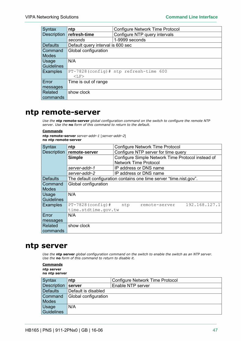
VIPA Networking Solutions Command Line Interface
HB165 | PNS | 911-2PNx0 | GB | 16-06 47
Syntax Description
ntp Configure Network Time Protocol refresh-time Configure NTP query intervals seconds 1-9999 seconds
Defaults Default query interval is 600 sec Command Modes
Global configuration
Usage Guidelines
N/A
Examples PT-7828(config)# ntp refresh-time 600
<LF>
Error messages
Time is out of range
Related commands
show clock
ntp remote-server Use the ntp remote-server global configuration command on the switch to configure the remote NTP server. Use the no form of this command to return to the default.
Commands
ntp remote-server server-addr-1 [server-addr-2] no ntp remote-server
Syntax Description
ntp Configure Network Time Protocol remote-server Configure NTP server for time query Simple Configure Simple Network Time Protocol instead of
Network Time Protocol server-addr-1 IP address or DNS name server-addr-2 IP address or DNS name
Defaults The default configuration contains one time server “time.nist.gov”. Command Modes
Global configuration
Usage Guidelines
N/A
Examples PT-7828(config)# ntp remote-server 192.168.127.1
time.stdtime.gov.tw
Error messages
N/A
Related commands
show clock
ntp server Use the ntp server global configuration command on the switch to enable the switch as an NTP server. Use the no form of this command to return to disable it.
Commands
ntp server no ntp server
Syntax Description
ntp Configure Network Time Protocol server Enable NTP server
Defaults Default is disabled Command Modes
Global configuration
Usage Guidelines
N/A
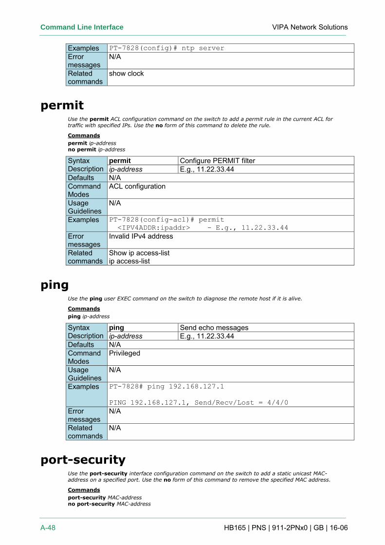
Command Line Interface VIPA Network Solutions
A-48 HB165 | PNS | 911-2PNx0 | GB | 16-06
Examples PT-7828(config)# ntp server
Error messages
N/A
Related commands
show clock
permit Use the permit ACL configuration command on the switch to add a permit rule in the current ACL for traffic with specified IPs. Use the no form of this command to delete the rule.
Commands
permit ip-address no permit ip-address
Syntax Description
permit Configure PERMIT filter ip-address E.g., 11.22.33.44
Defaults N/A Command Modes
ACL configuration
Usage Guidelines
N/A
Examples PT-7828(config-acl)# permit
<IPV4ADDR:ipaddr> - E.g., 11.22.33.44
Error messages
Invalid IPv4 address
Related commands
Show ip access-list ip access-list
ping Use the ping user EXEC command on the switch to diagnose the remote host if it is alive.
Commands
ping ip-address
Syntax Description
ping Send echo messages ip-address E.g., 11.22.33.44
Defaults N/A Command Modes
Privileged
Usage Guidelines
N/A
Examples PT-7828# ping 192.168.127.1
PING 192.168.127.1, Send/Recv/Lost = 4/4/0
Error messages
N/A
Related commands
N/A
port-security Use the port-security interface configuration command on the switch to add a static unicast MAC-address on a specified port. Use the no form of this command to remove the specified MAC address.
Commands
port-security MAC-address no port-security MAC-address
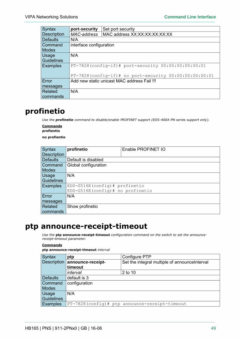
VIPA Networking Solutions Command Line Interface
HB165 | PNS | 911-2PNx0 | GB | 16-06 49
Syntax Description
port-security Set port security MAC-address MAC address XX:XX:XX:XX:XX:XX
Defaults N/A Command Modes
interface configuration
Usage Guidelines
N/A
Examples PT-7828(config-if)# port-security 00:00:00:00:00:01
PT-7828(config-if)# no port-security 00:00:00:00:00:01
Error messages
Add new static unicast MAC address Fail !!!
Related commands
N/A
profinetio Use the profinetio command to disable/enable PROFINET support (EDS-400A-PN series support only).
Commands
profientio
no profientio
Syntax Description
profinetio Enable PROFINET IO
Defaults Default is disabled Command Modes
Global configuration
Usage Guidelines
N/A
Examples EDS-G516E(config)# profinetio
EDS-G516E(config)# no profinetio
Error messages
N/A
Related commands
Show profinetio
ptp announce-receipt-timeout Use the ptp announce-receipt-timeout configuration command on the switch to set the announce-receipt-timeout parameter.
Commands
ptp announce-receipt-timeout interval
Syntax Description
ptp Configure PTP announce-receipt-timeout
Set the integral multiple of announceInterval
interval 2 to 10 Defaults default is 3 Command Modes
configuration
Usage Guidelines
N/A
Examples PT-7828(config)# ptp announce-receipt-timeout
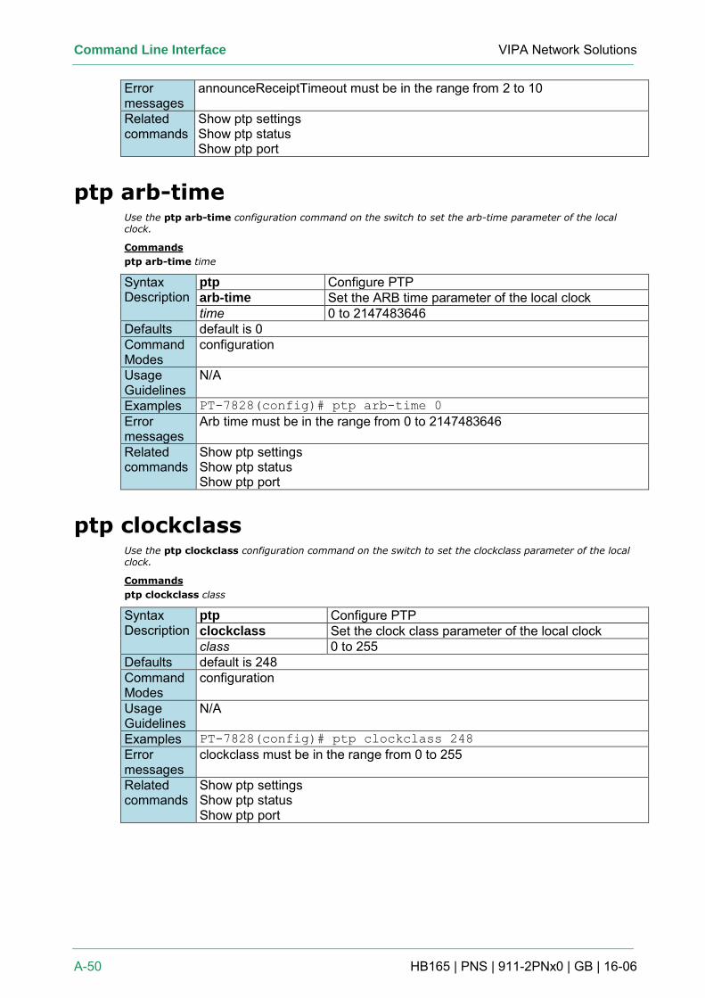
Command Line Interface VIPA Network Solutions
A-50 HB165 | PNS | 911-2PNx0 | GB | 16-06
Error messages
announceReceiptTimeout must be in the range from 2 to 10
Related commands
Show ptp settings Show ptp status Show ptp port
ptp arb-time Use the ptp arb-time configuration command on the switch to set the arb-time parameter of the local clock.
Commands
ptp arb-time time
Syntax Description
ptp Configure PTP arb-time Set the ARB time parameter of the local clock time 0 to 2147483646
Defaults default is 0 Command Modes
configuration
Usage Guidelines
N/A
Examples PT-7828(config)# ptp arb-time 0
Error messages
Arb time must be in the range from 0 to 2147483646
Related commands
Show ptp settings Show ptp status Show ptp port
ptp clockclass Use the ptp clockclass configuration command on the switch to set the clockclass parameter of the local clock.
Commands
ptp clockclass class
Syntax Description
ptp Configure PTP clockclass Set the clock class parameter of the local clock class 0 to 255
Defaults default is 248 Command Modes
configuration
Usage Guidelines
N/A
Examples PT-7828(config)# ptp clockclass 248
Error messages
clockclass must be in the range from 0 to 255
Related commands
Show ptp settings Show ptp status Show ptp port
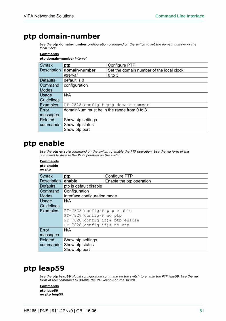
VIPA Networking Solutions Command Line Interface
HB165 | PNS | 911-2PNx0 | GB | 16-06 51
ptp domain-number Use the ptp domain-number configuration command on the switch to set the domain number of the local clock.
Commands
ptp domain-number interval
Syntax Description
ptp Configure PTP domain-number Set the domain number of the local clock interval 0 to 3
Defaults default is 0 Command Modes
configuration
Usage Guidelines
N/A
Examples PT-7828(config)# ptp domain-number
Error messages
domainNum must be in the range from 0 to 3
Related commands
Show ptp settings Show ptp status Show ptp port
ptp enable Use the ptp enable command on the switch to enable the PTP operation. Use the no form of this command to disable the PTP operation on the switch.
Commands
ptp enable no ptp
Syntax Description
ptp Configure PTP enable Enable the ptp operation
Defaults ptp is default disable Command Modes
Configuration Interface configuration mode
Usage Guidelines
N/A
Examples PT-7828(config)# ptp enable
PT-7828(config)# no ptp
PT-7828(config-if)# ptp enable
PT-7828(config-if)# no ptp
Error messages
N/A
Related commands
Show ptp settings Show ptp status Show ptp port
ptp leap59 Use the ptp leap59 global configuration command on the switch to enable the PTP leap59. Use the no form of this command to disable the PTP leap59 on the switch.
Commands
ptp leap59 no ptp leap59
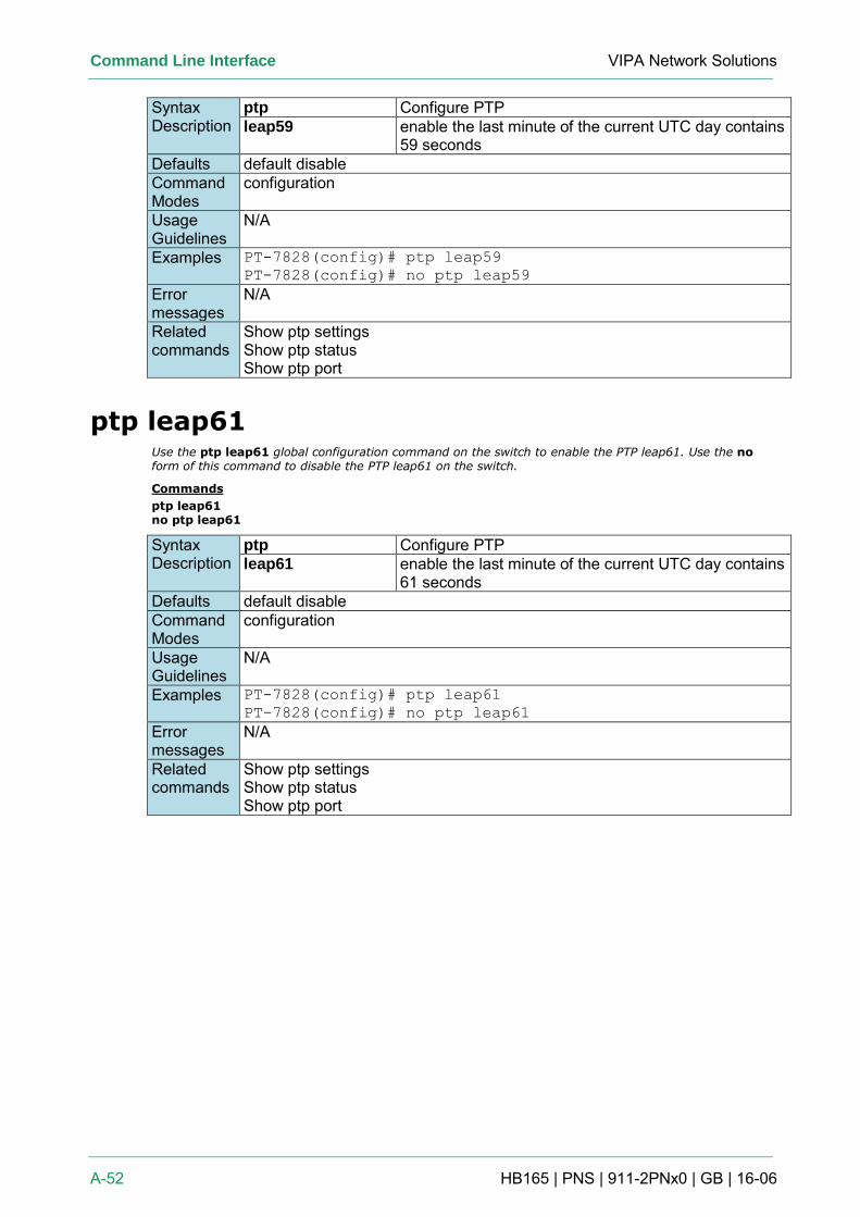
Command Line Interface VIPA Network Solutions
A-52 HB165 | PNS | 911-2PNx0 | GB | 16-06
Syntax Description
ptp Configure PTP leap59 enable the last minute of the current UTC day contains
59 seconds Defaults default disable Command Modes
configuration
Usage Guidelines
N/A
Examples PT-7828(config)# ptp leap59
PT-7828(config)# no ptp leap59
Error messages
N/A
Related commands
Show ptp settings Show ptp status Show ptp port
ptp leap61 Use the ptp leap61 global configuration command on the switch to enable the PTP leap61. Use the no form of this command to disable the PTP leap61 on the switch.
Commands
ptp leap61 no ptp leap61
Syntax Description
ptp Configure PTP leap61 enable the last minute of the current UTC day contains
61 seconds Defaults default disable Command Modes
configuration
Usage Guidelines
N/A
Examples PT-7828(config)# ptp leap61
PT-7828(config)# no ptp leap61
Error messages
N/A
Related commands
Show ptp settings Show ptp status Show ptp port
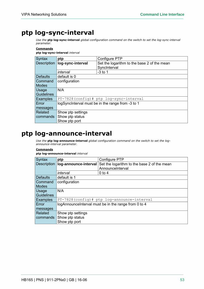
VIPA Networking Solutions Command Line Interface
HB165 | PNS | 911-2PNx0 | GB | 16-06 53
ptp log-sync-interval Use the ptp log-sync-interval global configuration command on the switch to set the log-sync-interval parameter.
Commands
ptp log-sync-interval interval
Syntax Description
ptp Configure PTP log-sync-interval Set the logarithm to the base 2 of the mean
SyncInterval interval -3 to 1
Defaults default is 0 Command Modes
configuration
Usage Guidelines
N/A
Examples PT-7828(config)# ptp log-sync-interval
Error messages
logSyncInterval must be in the range from -3 to 1
Related commands
Show ptp settings Show ptp status Show ptp port
ptp log-announce-interval Use the ptp log-announce-interval global configuration command on the switch to set the log-announce-interval parameter.
Commands
ptp log-announce-interval interval
Syntax Description
ptp Configure PTP log-announce-interval Set the logarithm to the base 2 of the mean
AnnounceInterval interval 0 to 4
Defaults default is 1 Command Modes
configuration
Usage Guidelines
N/A
Examples PT-7828(config)# ptp log-announce-interval
Error messages
logAnnounceInterval must be in the range from 0 to 4
Related commands
Show ptp settings Show ptp status Show ptp port
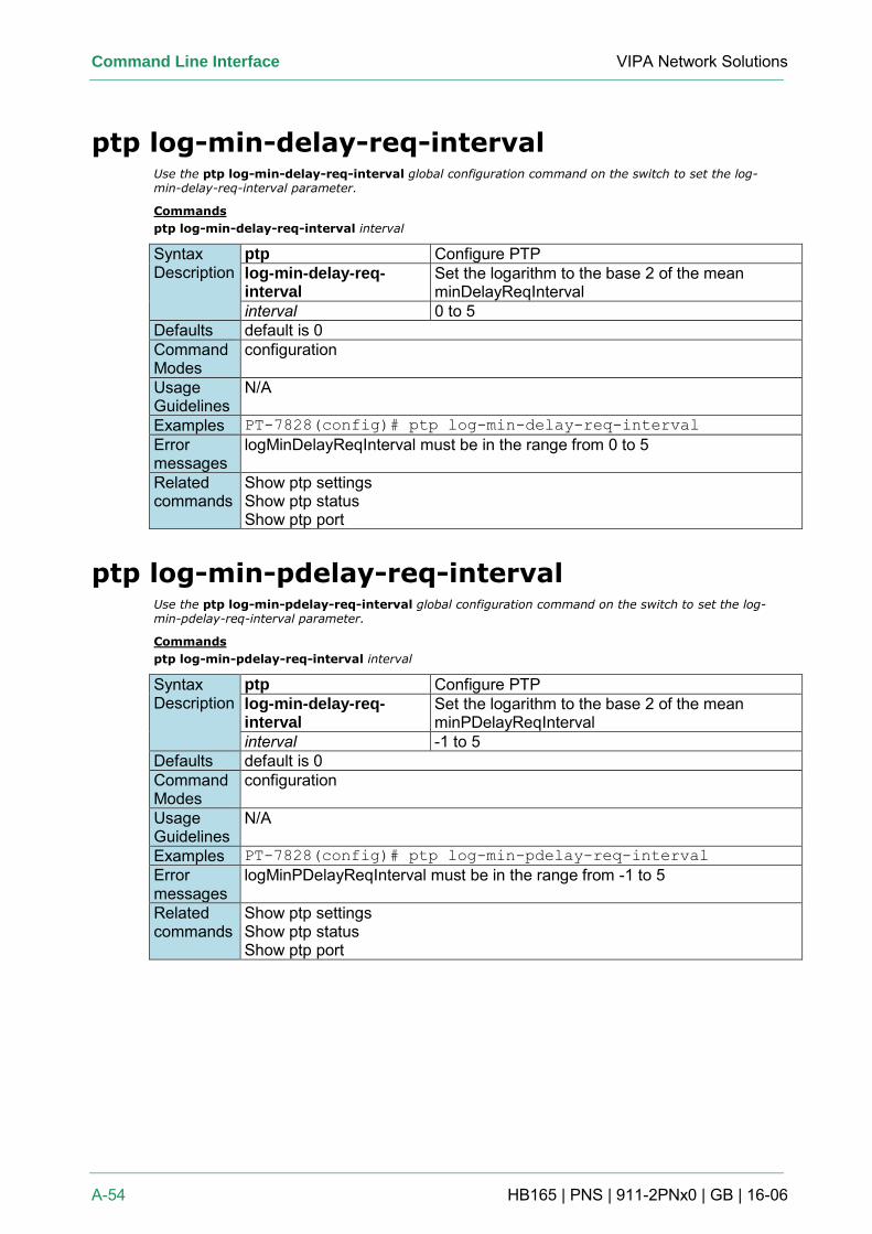
Command Line Interface VIPA Network Solutions
A-54 HB165 | PNS | 911-2PNx0 | GB | 16-06
ptp log-min-delay-req-interval Use the ptp log-min-delay-req-interval global configuration command on the switch to set the log-min-delay-req-interval parameter.
Commands
ptp log-min-delay-req-interval interval
Syntax Description
ptp Configure PTP log-min-delay-req-interval
Set the logarithm to the base 2 of the mean minDelayReqInterval
interval 0 to 5 Defaults default is 0 Command Modes
configuration
Usage Guidelines
N/A
Examples PT-7828(config)# ptp log-min-delay-req-interval
Error messages
logMinDelayReqInterval must be in the range from 0 to 5
Related commands
Show ptp settings Show ptp status Show ptp port
ptp log-min-pdelay-req-interval Use the ptp log-min-pdelay-req-interval global configuration command on the switch to set the log-min-pdelay-req-interval parameter.
Commands
ptp log-min-pdelay-req-interval interval
Syntax Description
ptp Configure PTP log-min-delay-req-interval
Set the logarithm to the base 2 of the mean minPDelayReqInterval
interval -1 to 5 Defaults default is 0 Command Modes
configuration
Usage Guidelines
N/A
Examples PT-7828(config)# ptp log-min-pdelay-req-interval
Error messages
logMinPDelayReqInterval must be in the range from -1 to 5
Related commands
Show ptp settings Show ptp status Show ptp port
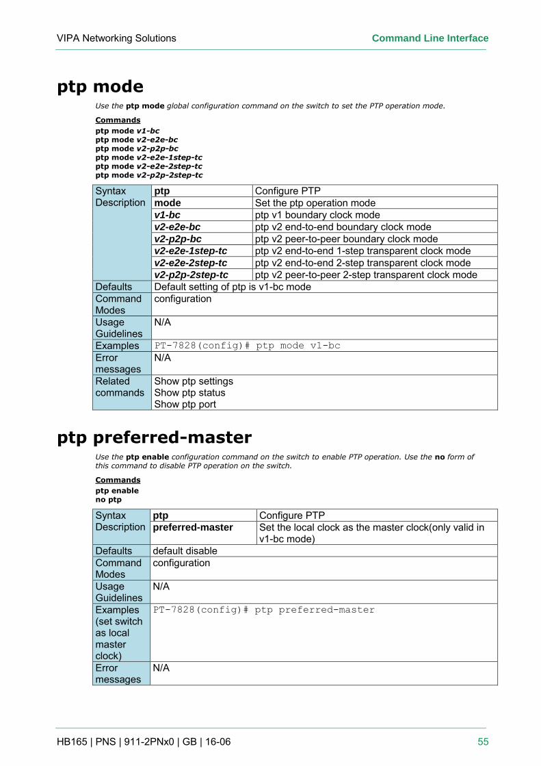
VIPA Networking Solutions Command Line Interface
HB165 | PNS | 911-2PNx0 | GB | 16-06 55
ptp mode Use the ptp mode global configuration command on the switch to set the PTP operation mode.
Commands
ptp mode v1-bc ptp mode v2-e2e-bc ptp mode v2-p2p-bc ptp mode v2-e2e-1step-tc ptp mode v2-e2e-2step-tc ptp mode v2-p2p-2step-tc
Syntax Description
ptp Configure PTP mode Set the ptp operation mode v1-bc ptp v1 boundary clock mode v2-e2e-bc ptp v2 end-to-end boundary clock mode v2-p2p-bc ptp v2 peer-to-peer boundary clock mode v2-e2e-1step-tc ptp v2 end-to-end 1-step transparent clock mode v2-e2e-2step-tc ptp v2 end-to-end 2-step transparent clock mode v2-p2p-2step-tc ptp v2 peer-to-peer 2-step transparent clock mode
Defaults Default setting of ptp is v1-bc mode Command Modes
configuration
Usage Guidelines
N/A
Examples PT-7828(config)# ptp mode v1-bc
Error messages
N/A
Related commands
Show ptp settings Show ptp status Show ptp port
ptp preferred-master Use the ptp enable configuration command on the switch to enable PTP operation. Use the no form of this command to disable PTP operation on the switch.
Commands
ptp enable no ptp
Syntax Description
ptp Configure PTP preferred-master Set the local clock as the master clock(only valid in
v1-bc mode) Defaults default disable Command Modes
configuration
Usage Guidelines
N/A
Examples (set switch as local master clock)
PT-7828(config)# ptp preferred-master
Error messages
N/A
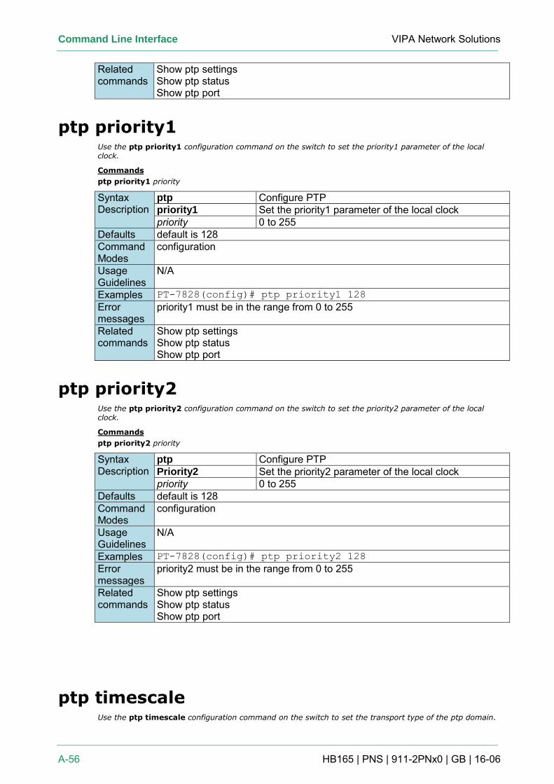
Command Line Interface VIPA Network Solutions
A-56 HB165 | PNS | 911-2PNx0 | GB | 16-06
Related commands
Show ptp settings Show ptp status Show ptp port
ptp priority1 Use the ptp priority1 configuration command on the switch to set the priority1 parameter of the local clock.
Commands
ptp priority1 priority
Syntax Description
ptp Configure PTP priority1 Set the priority1 parameter of the local clock priority 0 to 255
Defaults default is 128 Command Modes
configuration
Usage Guidelines
N/A
Examples PT-7828(config)# ptp priority1 128
Error messages
priority1 must be in the range from 0 to 255
Related commands
Show ptp settings Show ptp status Show ptp port
ptp priority2 Use the ptp priority2 configuration command on the switch to set the priority2 parameter of the local clock.
Commands
ptp priority2 priority
Syntax Description
ptp Configure PTP Priority2 Set the priority2 parameter of the local clock priority 0 to 255
Defaults default is 128 Command Modes
configuration
Usage Guidelines
N/A
Examples PT-7828(config)# ptp priority2 128
Error messages
priority2 must be in the range from 0 to 255
Related commands
Show ptp settings Show ptp status Show ptp port
ptp timescale Use the ptp timescale configuration command on the switch to set the transport type of the ptp domain.
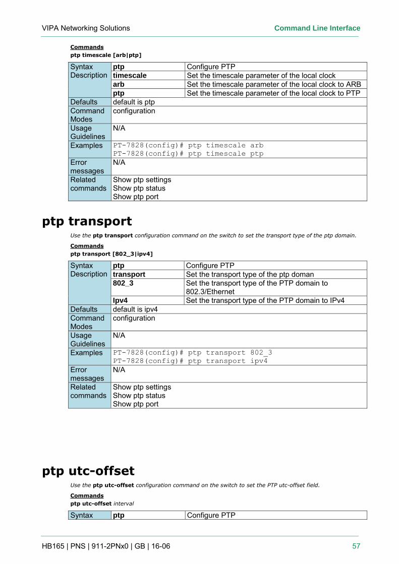
VIPA Networking Solutions Command Line Interface
HB165 | PNS | 911-2PNx0 | GB | 16-06 57
Commands
ptp timescale [arb|ptp]
Syntax Description
ptp Configure PTP timescale Set the timescale parameter of the local clock arb Set the timescale parameter of the local clock to ARB ptp Set the timescale parameter of the local clock to PTP
Defaults default is ptp Command Modes
configuration
Usage Guidelines
N/A
Examples PT-7828(config)# ptp timescale arb
PT-7828(config)# ptp timescale ptp
Error messages
N/A
Related commands
Show ptp settings Show ptp status Show ptp port
ptp transport Use the ptp transport configuration command on the switch to set the transport type of the ptp domain.
Commands
ptp transport [802_3|ipv4]
Syntax Description
ptp Configure PTP transport Set the transport type of the ptp doman 802_3 Set the transport type of the PTP domain to
802.3/Ethernet Ipv4 Set the transport type of the PTP domain to IPv4
Defaults default is ipv4 Command Modes
configuration
Usage Guidelines
N/A
Examples PT-7828(config)# ptp transport 802_3
PT-7828(config)# ptp transport ipv4
Error messages
N/A
Related commands
Show ptp settings Show ptp status Show ptp port
ptp utc-offset Use the ptp utc-offset configuration command on the switch to set the PTP utc-offset field.
Commands
ptp utc-offset interval
Syntax ptp Configure PTP
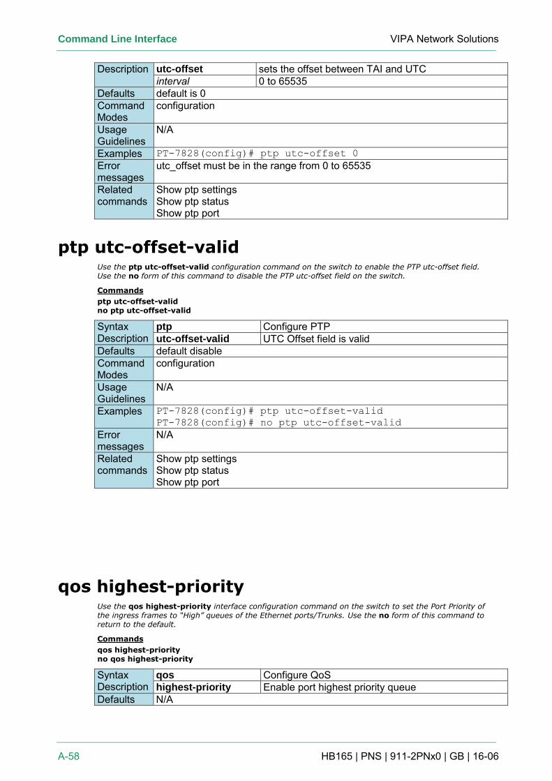
Command Line Interface VIPA Network Solutions
A-58 HB165 | PNS | 911-2PNx0 | GB | 16-06
Description utc-offset sets the offset between TAI and UTC interval 0 to 65535
Defaults default is 0 Command Modes
configuration
Usage Guidelines
N/A
Examples PT-7828(config)# ptp utc-offset 0
Error messages
utc_offset must be in the range from 0 to 65535
Related commands
Show ptp settings Show ptp status Show ptp port
ptp utc-offset-valid Use the ptp utc-offset-valid configuration command on the switch to enable the PTP utc-offset field. Use the no form of this command to disable the PTP utc-offset field on the switch.
Commands
ptp utc-offset-valid no ptp utc-offset-valid
Syntax Description
ptp Configure PTP utc-offset-valid UTC Offset field is valid
Defaults default disable Command Modes
configuration
Usage Guidelines
N/A
Examples PT-7828(config)# ptp utc-offset-valid
PT-7828(config)# no ptp utc-offset-valid
Error messages
N/A
Related commands
Show ptp settings Show ptp status Show ptp port
qos highest-priority Use the qos highest-priority interface configuration command on the switch to set the Port Priority of the ingress frames to “High” queues of the Ethernet ports/Trunks. Use the no form of this command to return to the default.
Commands
qos highest-priority no qos highest-priority
Syntax Description
qos Configure QoS highest-priority Enable port highest priority queue
Defaults N/A
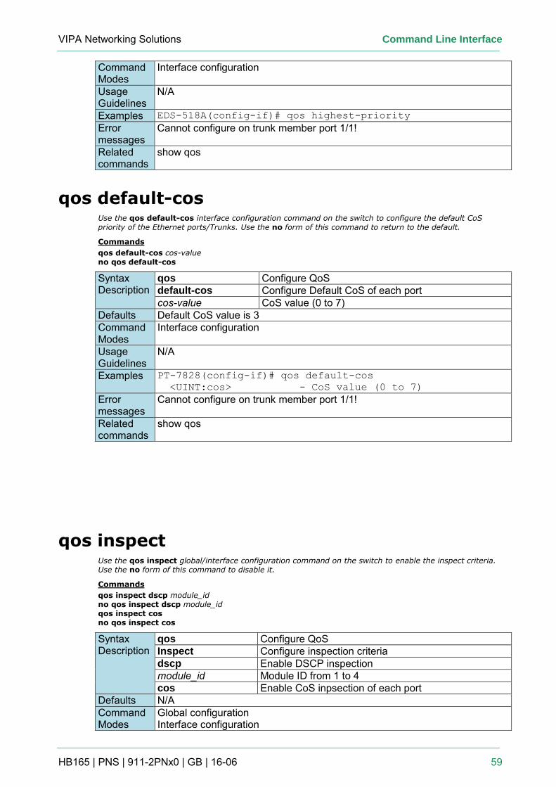
VIPA Networking Solutions Command Line Interface
HB165 | PNS | 911-2PNx0 | GB | 16-06 59
Command Modes
Interface configuration
Usage Guidelines
N/A
Examples EDS-518A(config-if)# qos highest-priority
Error messages
Cannot configure on trunk member port 1/1!
Related commands
show qos
qos default-cos Use the qos default-cos interface configuration command on the switch to configure the default CoS priority of the Ethernet ports/Trunks. Use the no form of this command to return to the default.
Commands
qos default-cos cos-value no qos default-cos
Syntax Description
qos Configure QoS default-cos Configure Default CoS of each port cos-value CoS value (0 to 7)
Defaults Default CoS value is 3 Command Modes
Interface configuration
Usage Guidelines
N/A
Examples PT-7828(config-if)# qos default-cos
<UINT:cos> - CoS value (0 to 7)
Error messages
Cannot configure on trunk member port 1/1!
Related commands
show qos
qos inspect Use the qos inspect global/interface configuration command on the switch to enable the inspect criteria. Use the no form of this command to disable it.
Commands
qos inspect dscp module_id no qos inspect dscp module_id qos inspect cos no qos inspect cos
Syntax Description
qos Configure QoS Inspect Configure inspection criteria dscp Enable DSCP inspection module_id Module ID from 1 to 4 cos Enable CoS inpsection of each port
Defaults N/A Command Modes
Global configuration Interface configuration
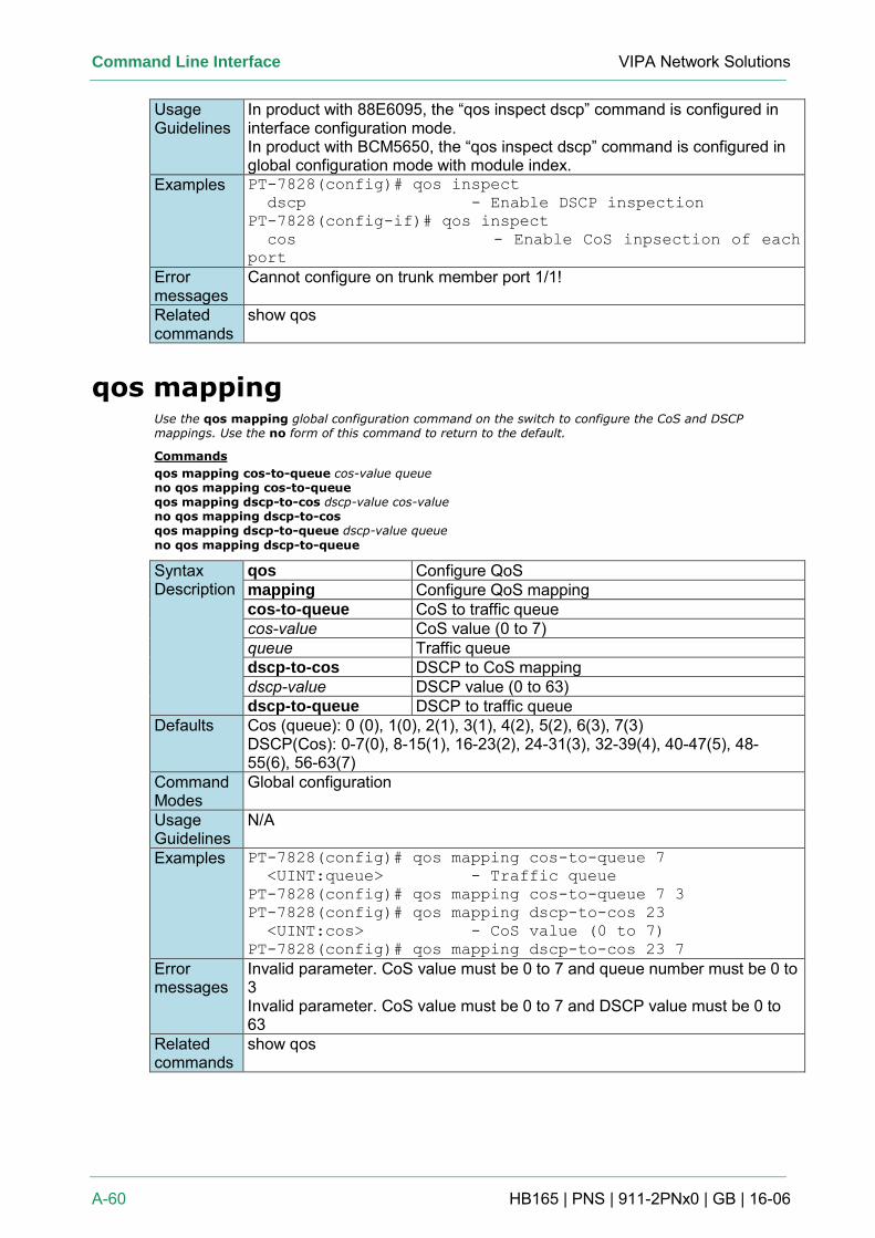
Command Line Interface VIPA Network Solutions
A-60 HB165 | PNS | 911-2PNx0 | GB | 16-06
Usage Guidelines
In product with 88E6095, the “qos inspect dscp” command is configured in interface configuration mode. In product with BCM5650, the “qos inspect dscp” command is configured in global configuration mode with module index.
Examples PT-7828(config)# qos inspect
dscp - Enable DSCP inspection
PT-7828(config-if)# qos inspect
cos - Enable CoS inpsection of each
port
Error messages
Cannot configure on trunk member port 1/1!
Related commands
show qos
qos mapping Use the qos mapping global configuration command on the switch to configure the CoS and DSCP mappings. Use the no form of this command to return to the default.
Commands
qos mapping cos-to-queue cos-value queue no qos mapping cos-to-queue qos mapping dscp-to-cos dscp-value cos-value no qos mapping dscp-to-cos qos mapping dscp-to-queue dscp-value queue
no qos mapping dscp-to-queue
Syntax Description
qos Configure QoS mapping Configure QoS mapping cos-to-queue CoS to traffic queue cos-value CoS value (0 to 7) queue Traffic queue dscp-to-cos DSCP to CoS mapping dscp-value DSCP value (0 to 63) dscp-to-queue DSCP to traffic queue
Defaults Cos (queue): 0 (0), 1(0), 2(1), 3(1), 4(2), 5(2), 6(3), 7(3) DSCP(Cos): 0-7(0), 8-15(1), 16-23(2), 24-31(3), 32-39(4), 40-47(5), 48-55(6), 56-63(7)
Command Modes
Global configuration
Usage Guidelines
N/A
Examples PT-7828(config)# qos mapping cos-to-queue 7
<UINT:queue> - Traffic queue
PT-7828(config)# qos mapping cos-to-queue 7 3
PT-7828(config)# qos mapping dscp-to-cos 23
<UINT:cos> - CoS value (0 to 7)
PT-7828(config)# qos mapping dscp-to-cos 23 7
Error messages
Invalid parameter. CoS value must be 0 to 7 and queue number must be 0 to 3 Invalid parameter. CoS value must be 0 to 7 and DSCP value must be 0 to 63
Related commands
show qos
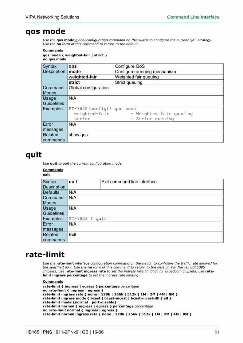
VIPA Networking Solutions Command Line Interface
HB165 | PNS | 911-2PNx0 | GB | 16-06 61
qos mode Use the qos mode global configuration command on the switch to configure the current QoS strategy. Use the no form of this command to return to the default.
Commands
qos mode { weighted-fair | strict } no qos mode
Syntax Description
qos Configure QoS mode Configure queuing mechanism weighted-fair Weighted fair queuing strict Strict queuing
Command Modes
Global configuration
Usage Guidelines
N/A
Examples PT-7828(config)# qos mode
weighted-fair - Weighted fair queuing
strict - Strict queuing
Error messages
N/A
Related commands
show qos
quit Use quit to quit the current configuration mode.
Commands
exit
Syntax Description
quit Exit command line interface
Defaults N/A Command Modes
N/A
Usage Guidelines
N/A
Examples PT-7828 # quit
Error messages
N/A
Related commands
Exit
rate-limit Use the rate-limit interface configuration command on the switch to configure the traffic rate allowed for the specified port. Use the no form of this command to return to the default. For Marvell 88E6095 chipsets, use rate-limit ingress rate to set the ingress rate limiting; for Broadcom chipsets, use rate-limit ingress percentage to set the ingress rate limiting.
Commands
rate-limit { ingress | egress } percentage percentage no rate-limit { ingress | egress } rate-limit ingress rate { none | 128k | 256k | 512k | 1M | 2M | 4M | 8M } rate-limit ingress mode { bcast | bcast-mcast | bcast-mcast-dlf | all } rate-limit mode {normal | port-disable}
rate-limit normal { ingress | egress } percentage percentage no rate-limit normal { ingress | egress } rate-limit normal ingress rate { none | 128k | 256k | 512k | 1M | 2M | 4M | 8M }
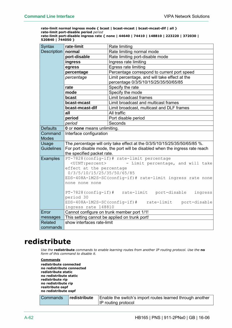
Command Line Interface VIPA Network Solutions
A-62 HB165 | PNS | 911-2PNx0 | GB | 16-06
rate-limit normal ingress mode { bcast | bcast-mcast | bcast-mcast-dlf | all } rate-limit port-disable period period rate-limit port-disable ingress rate { none | 44640 | 74410 | 148810 | 223220 | 372030 | 520840 | 744050 }
Syntax Description
rate-limit Rate limiting normal Rate limiting normal mode port-disable Rate limiting port-disable mode ingress Ingress rate limiting egress Egress rate limiting percentage Percentage correspond to current port speed percentage Limit percentage, and will take effect at the
percentage 0/3/5/10/15/25/35/50/65/85 rate Specify the rate mode Specify the mode bcast Limit broadcast frames bcast-mcast Limit broadcast and multicast frames bcast-mcast-dlf Limit broadcast, multicast and DLF frames all All traffic period Port disable period period Seconds
Defaults 0 or none means unlimiting. Command Modes
Interface configuration
Usage Guidelines
The percentage will only take effect at the 0/3/5/10/15/25/35/50/65/85 %. For port disable mode, the port will be disabled when the ingress rate reach the specified packet rate.
Examples PT-7828(config-if)# rate-limit percentage
<UINT:percent> - Limit percentage, and will take
effect at the percentage
0/3/5/10/15/25/35/50/65/85
EDS-408A-1M2S-SC(config-if)# rate-limit ingress rate none
none none none
PT-7828(config-if)# rate-limit port-disable ingress
period 30
EDS-408A-1M2S-SC(config-if)# rate-limit port-disable
ingress rate 148810
Error messages
Cannot configure on trunk member port 1/1! This setting cannot be applied on trunk port!
Related commands
show interfaces rate-limit
redistribute Use the redistribute commands to enable learning routes from another IP routing protocol. Use the no form of this command to disable it.
Commands
redistribute connected no redistribute connected redistribute static no redistribute static redistribute rip no redistribute rip resitribute ospf no redistribute ospf
Commands redistribute Enable the switch’s import routes learned through another IP routing protocol
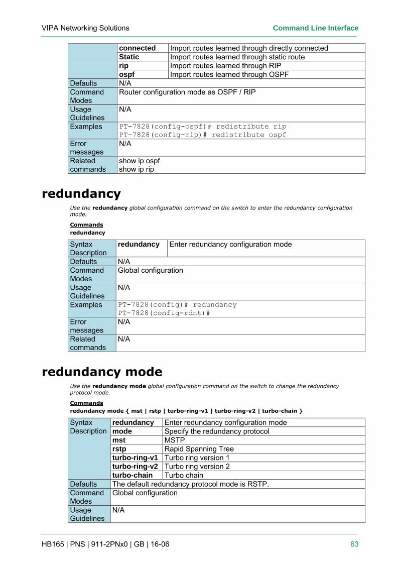
VIPA Networking Solutions Command Line Interface
HB165 | PNS | 911-2PNx0 | GB | 16-06 63
connected Import routes learned through directly connected Static Import routes learned through static route rip Import routes learned through RIP ospf Import routes learned through OSPF
Defaults N/A Command Modes
Router configuration mode as OSPF / RIP
Usage Guidelines
N/A
Examples PT-7828(config-ospf)# redistribute rip
PT-7828(config-rip)# redistribute ospf
Error messages
N/A
Related commands
show ip ospf show ip rip
redundancy Use the redundancy global configuration command on the switch to enter the redundancy configuration mode.
Commands
redundancy
Syntax Description
redundancy Enter redundancy configuration mode
Defaults N/A Command Modes
Global configuration
Usage Guidelines
N/A
Examples PT-7828(config)# redundancy
PT-7828(config-rdnt)#
Error messages
N/A
Related commands
N/A
redundancy mode Use the redundancy mode global configuration command on the switch to change the redundancy protocol mode.
Commands
redundancy mode { mst | rstp | turbo-ring-v1 | turbo-ring-v2 | turbo-chain }
Syntax Description
redundancy Enter redundancy configuration mode mode Specify the redundancy protocol mst MSTP rstp Rapid Spanning Tree turbo-ring-v1 Turbo ring version 1 turbo-ring-v2 Turbo ring version 2 turbo-chain Turbo chain
Defaults The default redundancy protocol mode is RSTP. Command Modes
Global configuration
Usage Guidelines
N/A
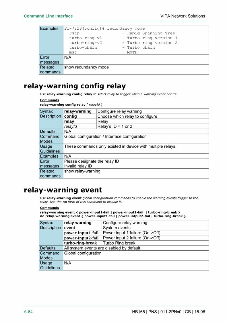
Command Line Interface VIPA Network Solutions
A-64 HB165 | PNS | 911-2PNx0 | GB | 16-06
Examples PT-7828(config)# redundancy mode
rstp - Rapid Spanning Tree
turbo-ring-v1 - Turbo ring version 1
turbo-ring-v2 - Turbo ring version 2
turbo-chain - Turbo chain
mst - MSTP
Error messages
N/A
Related commands
show redundancy mode
relay-warning config relay Use relay-warning config relay to select relay to trigger when a warning event occurs.
Commands
relay-warning config relay [ relayId ]
Syntax Description
relay-warning Configure relay warning config Choose which relay to configure relay Relay relayId Relay’s ID = 1 or 2
Defaults N/A Command Modes
Global configuration / Interface configuration
Usage Guidelines
These commands only existed in device with multiple relays.
Examples N/A Error messages
Please designate the relay ID Invalid relay ID
Related commands
show relay-warning
relay-warning event Use relay-warning event global configuration commands to enable the warning events trigger to the relay. Use the no form of this command to disable it.
Commands
relay-warning event { power-input1-fail | power-input2-fail | turbo-ring-break } no relay-warning event { power-input1-fail | power-intput2-fail | turbo-ring-break }
Syntax Description
relay-warning Configure relay warning event System events power-input1-fail Power input 1 failure (On->Off) power-input2-fail Power input 2 failure (On->Off) turbo-ring-break Turbo Ring break
Defaults All system events are disabled by default. Command Modes
Global configuration
Usage Guidelines
N/A
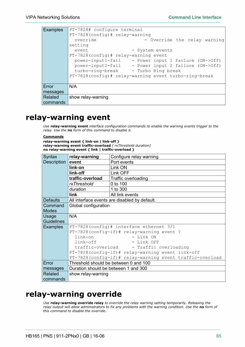
VIPA Networking Solutions Command Line Interface
HB165 | PNS | 911-2PNx0 | GB | 16-06 65
Examples PT-7828# configure terminal
PT-7828(config)# relay-warning
override - Override the relay warning
setting
event - System events
PT-7828(config)# relay-warning event
power-input1-fail - Power input 1 failure (ON->Off)
power-input2-fail - Power input 2 failure (ON->Off)
turbo-ring-break - Turbo Ring break
PT-7828(config)# relay-warning event turbo-ring-break
Error messages
N/A
Related commands
show relay-warning
relay-warning event Use relay-warning event interface configuration commands to enable the warning events trigger to the relay. Use the no form of this command to disable it.
Commands
relay-warning event { link-on | link-off }
relay-warning event traffic-overload [ rxThreshold duration] no relay-warning event { link | traffic-overload }
Syntax Description
relay-warning Configure relay warning event Port events link-on Link ON link-off Link OFF traffic-overload Traffic overloading rxThreshold 0 to 100 duration 1 to 300 link All link events
Defaults All interface events are disabled by default. Command Modes
Global configuration
Usage Guidelines
N/A
Examples PT-7828(config)# interface ethernet 3/1
PT-7828(config-if)# relay-warning event ?
link-on - Link ON
link-off - Link OFF
traffic-overload - Traffic overloading
PT-7828(config-if)# relay-warning event link-off
PT-7828(config-if)# relay-warning event traffic-overload
Error messages
Threshold should be between 0 and 100 Duration should be between 1 and 300
Related commands
show relay-warning
relay-warning override Use relay-warning override relay to override the relay warning setting temporarily. Releasing the relay output will allow administrators to fix any problems with the warning condition. Use the no form of this command to disable the override.
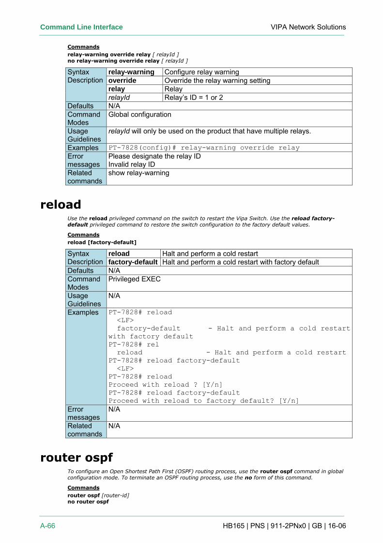
Command Line Interface VIPA Network Solutions
A-66 HB165 | PNS | 911-2PNx0 | GB | 16-06
Commands
relay-warning override relay [ relayId ] no relay-warning override relay [ relayId ]
Syntax Description
relay-warning Configure relay warning override Override the relay warning setting relay Relay relayId Relay’s ID = 1 or 2
Defaults N/A Command Modes
Global configuration
Usage Guidelines
relayId will only be used on the product that have multiple relays.
Examples PT-7828(config)# relay-warning override relay
Error messages
Please designate the relay ID Invalid relay ID
Related commands
show relay-warning
reload Use the reload privileged command on the switch to restart the Vipa Switch. Use the reload factory-default privileged command to restore the switch configuration to the factory default values.
Commands
reload [factory-default]
Syntax Description
reload Halt and perform a cold restart factory-default Halt and perform a cold restart with factory default
Defaults N/A Command Modes
Privileged EXEC
Usage Guidelines
N/A
Examples PT-7828# reload
<LF>
factory-default - Halt and perform a cold restart
with factory default
PT-7828# rel
reload - Halt and perform a cold restart
PT-7828# reload factory-default
<LF>
PT-7828# reload
Proceed with reload ? [Y/n]
PT-7828# reload factory-default
Proceed with reload to factory default? [Y/n]
Error messages
N/A
Related commands
N/A
router ospf To configure an Open Shortest Path First (OSPF) routing process, use the router ospf command in global configuration mode. To terminate an OSPF routing process, use the no form of this command.
Commands
router ospf [router-id] no router ospf
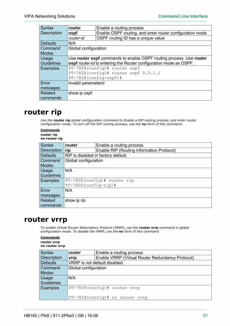
VIPA Networking Solutions Command Line Interface
HB165 | PNS | 911-2PNx0 | GB | 16-06 67
Syntax Description
router Enable a routing process ospf Enable OSPF routing, and enter router configuration mode router-id OSPF routing ID has a unique value
Defaults N/A Command Modes
Global configuration
Usage Guidelines
Use router ospf commands to enable OSPF routing process. Use router ospf router-id to entering the Router configuration mode as OSPF.
Examples PT-7828(config)# router ospf
PT-7828(config)# router ospf 0.0.1.1
PT-7828(config-ospf)#
Error messages
Invalid parameters!
Related commands
show ip ospf
router rip Use the router rip global configuration command to Enable a RIP routing process, and enter router configuration mode. To turn off the RIP routing process, use the no form of this command.
Commands
router rip no router rip
Syntax Description
router Enable a routing process rip Enable RIP (Routing Information Protocol)
Defaults RIP is disabled in factory default. Command Modes
Global configuration
Usage Guidelines
N/A
Examples PT-7828(config)# router rip
PT-7828(config-rip)#
Error messages
N/A
Related commands
show ip rip
router vrrp To enable Virtual Router Redundancy Protocol (VRRP), use the router vrrp command in global configuration mode. To disable the VRRP, use the no form of this command
Commands
router vrrp no router vrrp
Syntax Description
router Enable a routing process vrrp Enable VRRP (Virtual Router Redundancy Protocol)
Defaults VRRP is not default disabled. Command Modes
Global configuration
Usage Guidelines
N/A
Examples PT-7828(config)# router vrrp
PT-7828(config)# no router vrrp
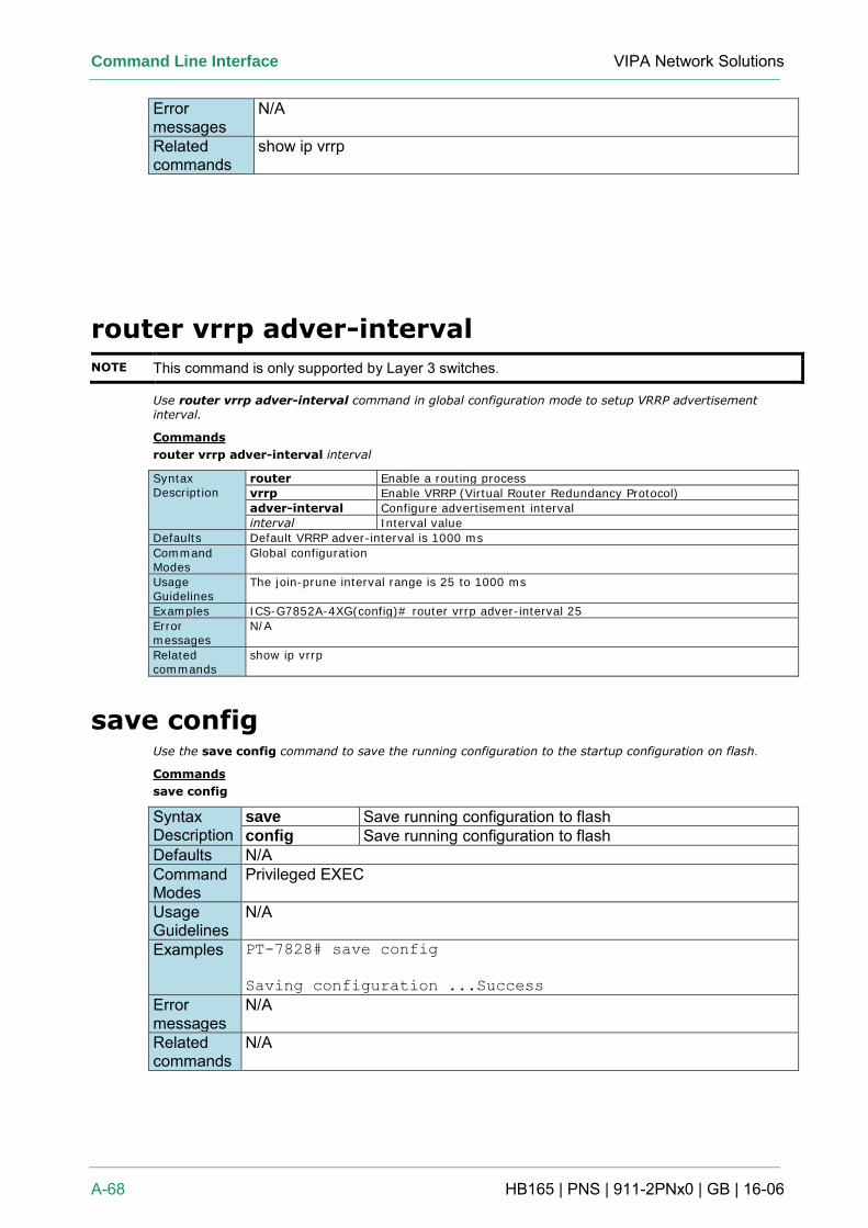
Command Line Interface VIPA Network Solutions
A-68 HB165 | PNS | 911-2PNx0 | GB | 16-06
Error messages
N/A
Related commands
show ip vrrp
router vrrp adver-interval
NOTE This command is only supported by Layer 3 switches.
Use router vrrp adver-interval command in global configuration mode to setup VRRP advertisement interval.
Commands
router vrrp adver-interval interval
Syntax Description
router Enable a routing process
vrrp Enable VRRP (Virtual Router Redundancy Protocol)
adver-interval Configure advertisement interval
interval Interval value
Defaults Default VRRP adver-interval is 1000 ms
Command Modes
Global configuration
Usage Guidelines
The join-prune interval range is 25 to 1000 ms
Examples ICS-G7852A-4XG(config)# router vrrp adver-interval 25
Error messages
N/A
Related commands
show ip vrrp
save config Use the save config command to save the running configuration to the startup configuration on flash.
Commands
save config
Syntax Description
save Save running configuration to flash config Save running configuration to flash
Defaults N/A Command Modes
Privileged EXEC
Usage Guidelines
N/A
Examples PT-7828# save config
Saving configuration ...Success
Error messages
N/A
Related commands
N/A
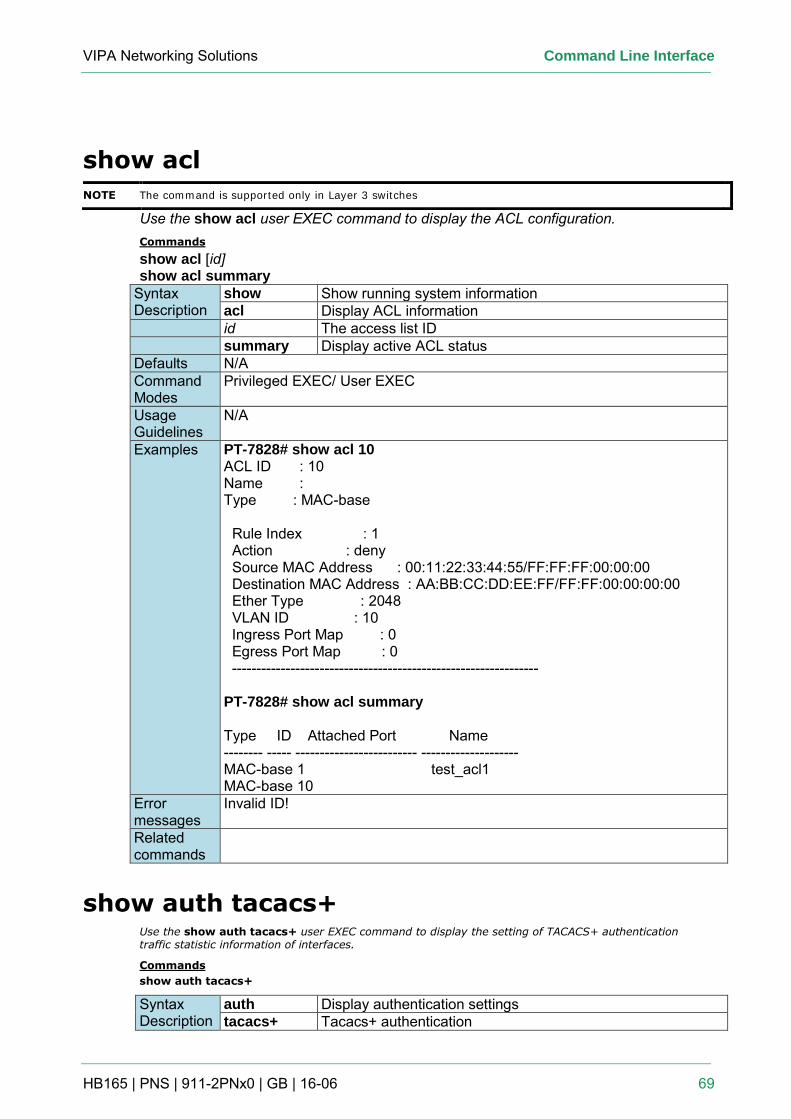
VIPA Networking Solutions Command Line Interface
HB165 | PNS | 911-2PNx0 | GB | 16-06 69
show acl
NOTE The command is supported only in Layer 3 switches
Use the show acl user EXEC command to display the ACL configuration. Commands
show acl [id] show acl summary
Syntax Description
show Show running system information acl Display ACL information
id The access list ID summary Display active ACL status Defaults N/A Command Modes
Privileged EXEC/ User EXEC
Usage Guidelines
N/A
Examples PT-7828# show acl 10 ACL ID : 10 Name : Type : MAC-base Rule Index : 1 Action : deny Source MAC Address : 00:11:22:33:44:55/FF:FF:FF:00:00:00 Destination MAC Address : AA:BB:CC:DD:EE:FF/FF:FF:00:00:00:00 Ether Type : 2048 VLAN ID : 10 Ingress Port Map : 0 Egress Port Map : 0 --------------------------------------------------------------- PT-7828# show acl summary Type ID Attached Port Name -------- ----- ------------------------- -------------------- MAC-base 1 test_acl1 MAC-base 10
Error messages
Invalid ID!
Related commands
show auth tacacs+ Use the show auth tacacs+ user EXEC command to display the setting of TACACS+ authentication traffic statistic information of interfaces.
Commands
show auth tacacs+
Syntax Description
auth Display authentication settings tacacs+ Tacacs+ authentication
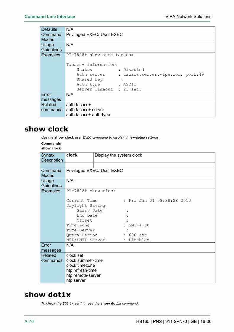
Command Line Interface VIPA Network Solutions
A-70 HB165 | PNS | 911-2PNx0 | GB | 16-06
Defaults N/A Command Modes
Privileged EXEC/ User EXEC
Usage Guidelines
N/A
Examples PT-7828# show auth tacacs+
Tacacs+ information:
Status : Disabled
Auth server : tacacs.server.vipa.com, port:49
Shared key :
Auth type : ASCII
Server Timeout : 23 sec.
Error messages
N/A
Related commands
auth tacacs+ auth tacacs+ server auth tacacs+ auth-type
show clock Use the show clock user EXEC command to display time-related settings.
Commands
show clock
Syntax Description
clock Display the system clock
Command Modes
Privileged EXEC/ User EXEC
Usage Guidelines
N/A
Examples PT-7828# show clock
Current Time : Fri Jan 01 08:38:28 2010
Daylight Saving
Start Date :
End Date :
Offset :
Time Zone : GMT-4:00
Time Server :
Query Period : 600 sec
NTP/SNTP Server : Disabled
Error messages
N/A
Related commands
clock set clock summer-time clock timezone ntp refresh-time ntp remote-server ntp server
show dot1x To check the 802.1x setting, use the show dot1x command.
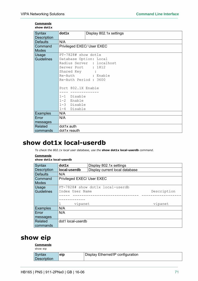
VIPA Networking Solutions Command Line Interface
HB165 | PNS | 911-2PNx0 | GB | 16-06 71
Commands
show dot1x
Syntax Description
dot1x Display 802.1x settings
Defaults N/A Command Modes
Privileged EXEC/ User EXEC
Usage Guidelines
PT-7828# show dot1x
Database Option: Local
Radius Server : localhost
Server Port : 1812
Shared Key :
Re-Auth : Enable
Re-Auth Period : 3600
Port 802.1X Enable
---- -------------
1-1 Disable
1-2 Enable
1-3 Disable
1-4 Disable
Examples N/A Error messages
N/A
Related commands
dot1x auth dot1x reauth
show dot1x local-userdb To check the 802.1x local user database, use the show dot1x local-userdb command.
Commands
show dot1x local-userdb
Syntax Description
dot1x Display 802.1x settings local-userdb Display current local database
Defaults N/A Command Modes
Privileged EXEC/ User EXEC
Usage Guidelines
PT-7828# show dot1x local-userdb
Index User Name Description
----- ------------------------------ ------------------
------------
1 vipanet vipanet
Examples N/A Error messages
N/A
Related commands
dot1 local-userdb
show eip Commands
show eip
Syntax Description
eip Display Ethernet/IP configuration
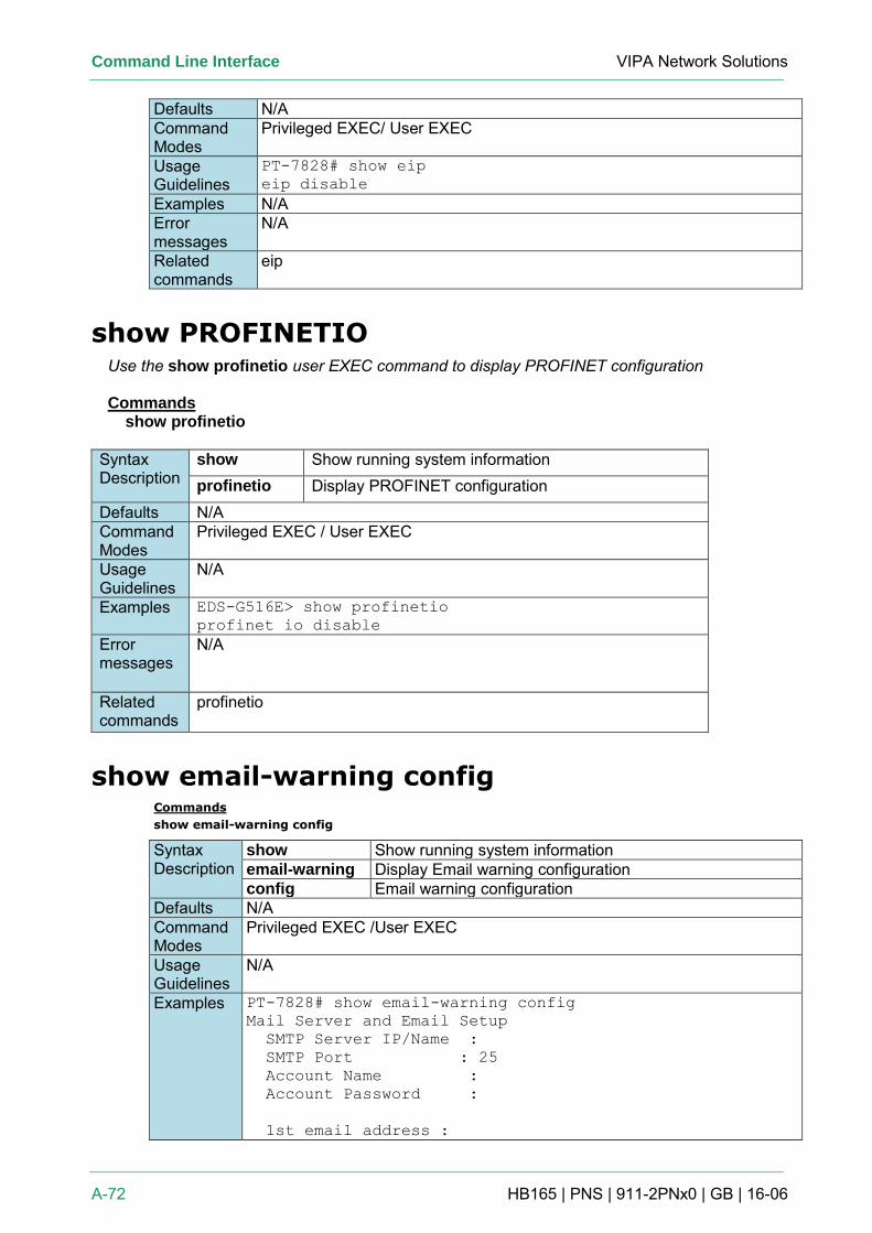
Command Line Interface VIPA Network Solutions
A-72 HB165 | PNS | 911-2PNx0 | GB | 16-06
Defaults N/A Command Modes
Privileged EXEC/ User EXEC
Usage Guidelines
PT-7828# show eip
eip disable
Examples N/A Error messages
N/A
Related commands
eip
show PROFINETIO Use the show profinetio user EXEC command to display PROFINET configuration
Commands
show profinetio
Syntax Description
show Show running system information profinetio Display PROFINET configuration
Defaults N/A Command Modes
Privileged EXEC / User EXEC
Usage Guidelines
N/A
Examples EDS-G516E> show profinetio
profinet io disable
Error messages
N/A
Related commands
profinetio
show email-warning config Commands
show email-warning config
Syntax Description
show Show running system information email-warning Display Email warning configuration config Email warning configuration
Defaults N/A Command Modes
Privileged EXEC /User EXEC
Usage Guidelines
N/A
Examples PT-7828# show email-warning config
Mail Server and Email Setup
SMTP Server IP/Name :
SMTP Port : 25
Account Name :
Account Password :
1st email address :
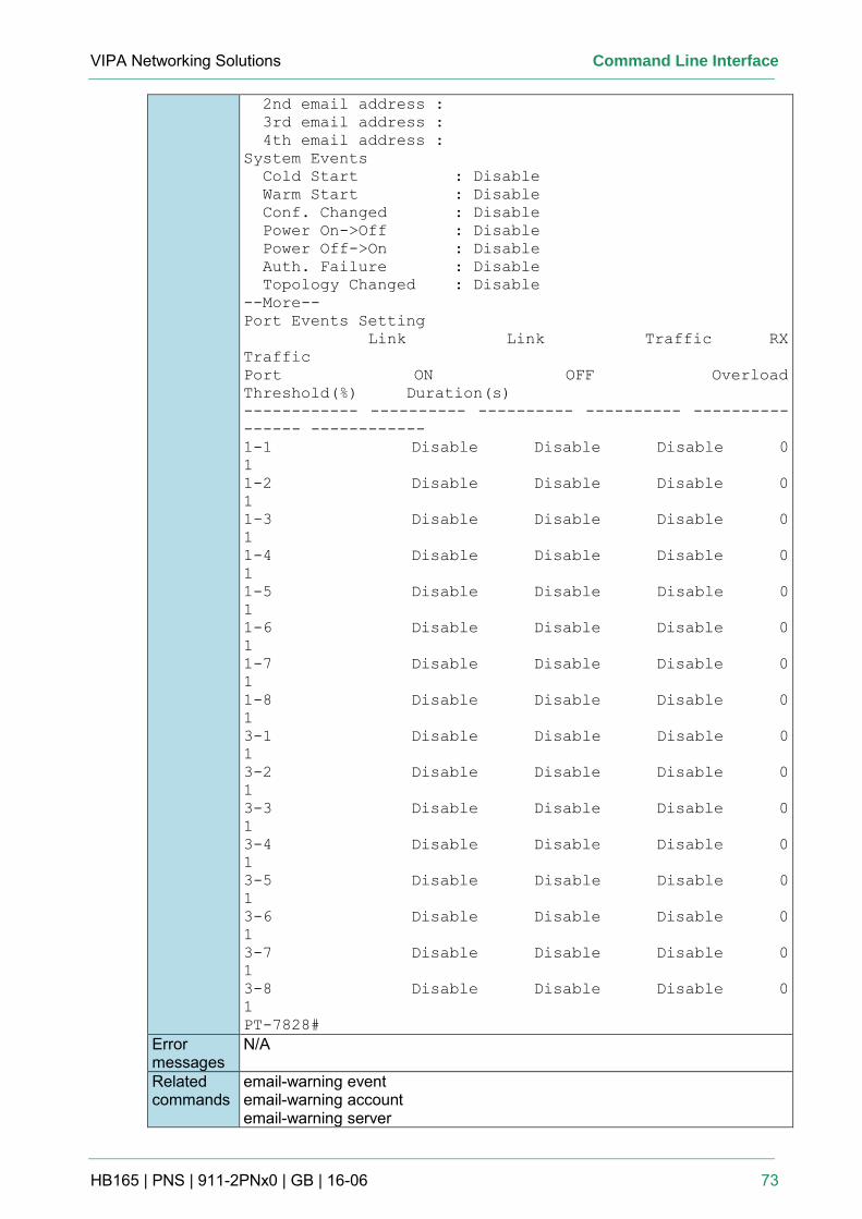
VIPA Networking Solutions Command Line Interface
HB165 | PNS | 911-2PNx0 | GB | 16-06 73
2nd email address :
3rd email address :
4th email address :
System Events
Cold Start : Disable
Warm Start : Disable
Conf. Changed : Disable
Power On->Off : Disable
Power Off->On : Disable
Auth. Failure : Disable
Topology Changed : Disable
--More--
Port Events Setting
Link Link Traffic RX
Traffic
Port ON OFF Overload
Threshold(%) Duration(s)
------------ ---------- ---------- ---------- ----------
------ ------------
1-1 Disable Disable Disable 0
1
1-2 Disable Disable Disable 0
1
1-3 Disable Disable Disable 0
1
1-4 Disable Disable Disable 0
1
1-5 Disable Disable Disable 0
1
1-6 Disable Disable Disable 0
1
1-7 Disable Disable Disable 0
1
1-8 Disable Disable Disable 0
1
3-1 Disable Disable Disable 0
1
3-2 Disable Disable Disable 0
1
3-3 Disable Disable Disable 0
1
3-4 Disable Disable Disable 0
1
3-5 Disable Disable Disable 0
1
3-6 Disable Disable Disable 0
1
3-7 Disable Disable Disable 0
1
3-8 Disable Disable Disable 0
1
PT-7828#
Error messages
N/A
Related commands
email-warning event email-warning account email-warning server
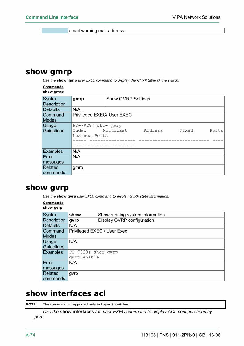
Command Line Interface VIPA Network Solutions
A-74 HB165 | PNS | 911-2PNx0 | GB | 16-06
email-warning mail-address
show gmrp Use the show igmp user EXEC command to display the GMRP table of the switch.
Commands
show gmrp
Syntax Description
gmrp Show GMRP Settings
Defaults N/A Command Modes
Privileged EXEC/ User EXEC
Usage Guidelines
PT-7828# show gmrp
Index Multicast Address Fixed Ports
Learned Ports
----- ----------------- -------------------------- ----
-----------------------
Examples N/A Error messages
N/A
Related commands
gmrp
show gvrp Use the show gvrp user EXEC command to display GVRP state information.
Commands
show gvrp
Syntax Description
show Show running system information gvrp Display GVRP configuration
Defaults N/A Command Modes
Privileged EXEC / User Exec
Usage Guidelines
N/A
Examples PT-7828# show gvrp
gvrp enable
Error messages
N/A
Related commands
gvrp
show interfaces acl
NOTE The command is supported only in Layer 3 switches
Use the show interfaces acl user EXEC command to display ACL configurations by port.
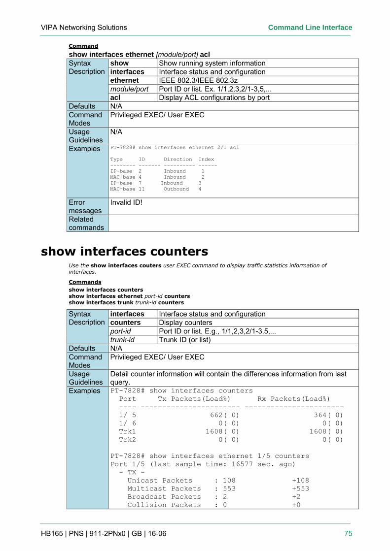
VIPA Networking Solutions Command Line Interface
HB165 | PNS | 911-2PNx0 | GB | 16-06 75
Command
show interfaces ethernet [module/port] acl Syntax Description
show Show running system information interfaces Interface status and configuration ethernet IEEE 802.3/IEEE 802.3z module/port Port ID or list. Ex. 1/1,2,3,2/1-3,5,... acl Display ACL configurations by port
Defaults N/A Command Modes
Privileged EXEC/ User EXEC
Usage Guidelines
N/A
Examples PT-7828# show interfaces ethernet 2/1 acl
Type ID Direction Index
-------- ------- ---------- ------
IP-base 2 Inbound 1
MAC-base 4 Inbound 2
IP-base 7 Inbound 3
MAC-base 11 Outbound 4
Error messages
Invalid ID!
Related commands
show interfaces counters Use the show interfaces couters user EXEC command to display traffic statistics information of interfaces.
Commands
show interfaces counters show interfaces ethernet port-id counters show interfaces trunk trunk-id counters
Syntax Description
interfaces Interface status and configuration counters Display counters port-id Port ID or list. E.g., 1/1,2,3,2/1-3,5,... trunk-id Trunk ID (or list)
Defaults N/A Command Modes
Privileged EXEC/ User EXEC
Usage Guidelines
Detail counter information will contain the differences information from last query.
Examples PT-7828# show interfaces counters
Port Tx Packets(Load%) Rx Packets(Load%)
---- ----------------------- -----------------------
1/ 5 662( 0) 364( 0)
1/ 6 0( 0) 0( 0)
Trk1 1608( 0) 1608( 0)
Trk2 0( 0) 0( 0)
PT-7828# show interfaces ethernet 1/5 counters
Port 1/5 (last sample time: 16577 sec. ago)
- TX -
Unicast Packets : 108 +108
Multicast Packets : 553 +553
Broadcast Packets : 2 +2
Collision Packets : 0 +0
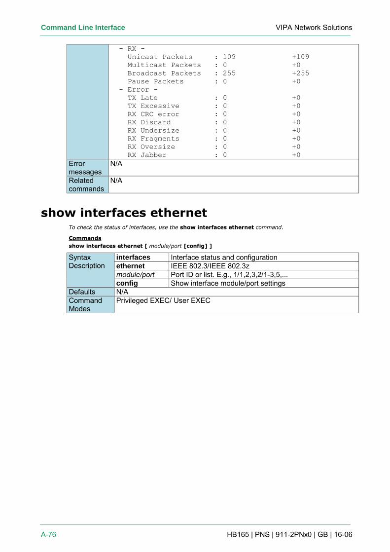
Command Line Interface VIPA Network Solutions
A-76 HB165 | PNS | 911-2PNx0 | GB | 16-06
- RX -
Unicast Packets : 109 +109
Multicast Packets : 0 +0
Broadcast Packets : 255 +255
Pause Packets : 0 +0
- Error -
TX Late : 0 +0
TX Excessive : 0 +0
RX CRC error : 0 +0
RX Discard : 0 +0
RX Undersize : 0 +0
RX Fragments : 0 +0
RX Oversize : 0 +0
RX Jabber : 0 +0
Error messages
N/A
Related commands
N/A
show interfaces ethernet To check the status of interfaces, use the show interfaces ethernet command.
Commands
show interfaces ethernet [ module/port [config] ]
Syntax Description
interfaces Interface status and configuration ethernet IEEE 802.3/IEEE 802.3z module/port Port ID or list. E.g., 1/1,2,3,2/1-3,5,... config Show interface module/port settings
Defaults N/A Command Modes
Privileged EXEC/ User EXEC
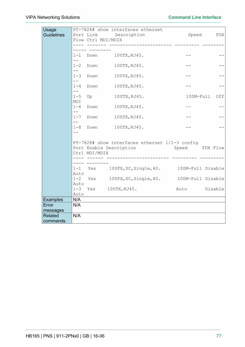
VIPA Networking Solutions Command Line Interface
HB165 | PNS | 911-2PNx0 | GB | 16-06 77
Usage Guidelines
PT-7828# show interfaces ethernet
Port Link Description Speed FDX
Flow Ctrl MDI/MDIX
---- ------- ----------------------- --------- --------
----- --------
1-1 Down 100TX,RJ45. -- --
--
1-2 Down 100TX,RJ45. -- --
--
1-3 Down 100TX,RJ45. -- --
--
1-4 Down 100TX,RJ45. -- --
--
1-5 Up 100TX,RJ45. 100M-Full Off
MDI
1-6 Down 100TX,RJ45. -- --
--
1-7 Down 100TX,RJ45. -- --
--
1-8 Down 100TX,RJ45. -- --
--
PT-7828# show interfaces ethernet 1/1-3 config
Port Enable Description Speed FDX Flow
Ctrl MDI/MDIX
---- ------ ----------------------- --------- ---------
---- --------
1-1 Yes 100FX,SC,Single,40. 100M-Full Disable
Auto
1-2 Yes 100FX,SC,Single,40. 100M-Full Disable
Auto
1-3 Yes 100TX,RJ45. Auto Disable
Auto
Examples N/A Error messages
N/A
Related commands
N/A
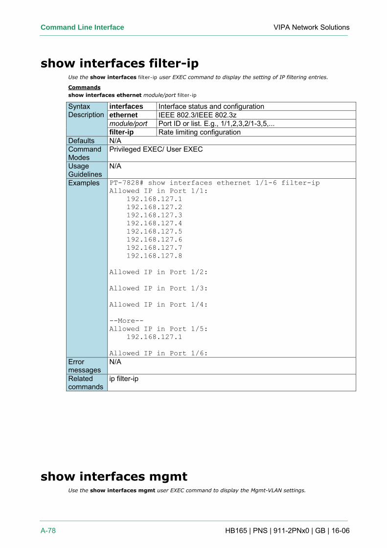
Command Line Interface VIPA Network Solutions
A-78 HB165 | PNS | 911-2PNx0 | GB | 16-06
show interfaces filter-ip Use the show interfaces filter-ip user EXEC command to display the setting of IP filtering entries.
Commands
show interfaces ethernet module/port filter-ip
Syntax Description
interfaces Interface status and configuration ethernet IEEE 802.3/IEEE 802.3z module/port Port ID or list. E.g., 1/1,2,3,2/1-3,5,... filter-ip Rate limiting configuration
Defaults N/A Command Modes
Privileged EXEC/ User EXEC
Usage Guidelines
N/A
Examples PT-7828# show interfaces ethernet 1/1-6 filter-ip
Allowed IP in Port 1/1:
192.168.127.1
192.168.127.2
192.168.127.3
192.168.127.4
192.168.127.5
192.168.127.6
192.168.127.7
192.168.127.8
Allowed IP in Port 1/2:
Allowed IP in Port 1/3:
Allowed IP in Port 1/4:
--More--
Allowed IP in Port 1/5:
192.168.127.1
Allowed IP in Port 1/6:
Error messages
N/A
Related commands
ip filter-ip
show interfaces mgmt Use the show interfaces mgmt user EXEC command to display the Mgmt-VLAN settings.
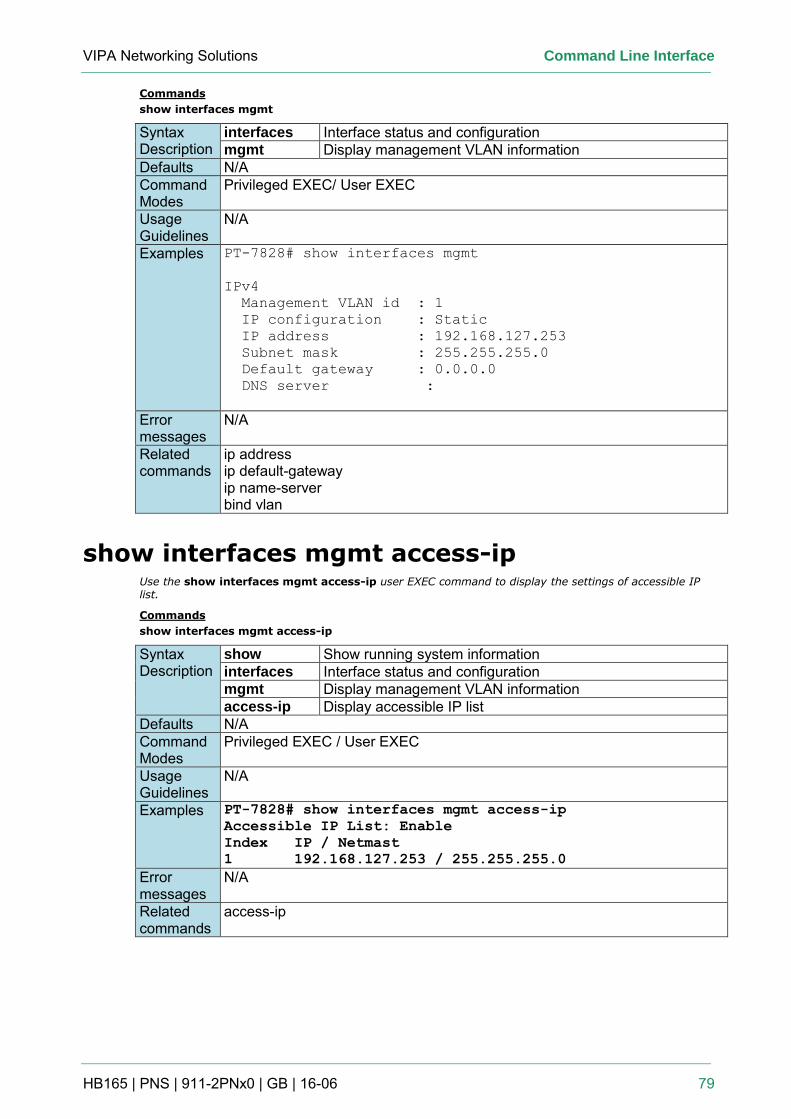
VIPA Networking Solutions Command Line Interface
HB165 | PNS | 911-2PNx0 | GB | 16-06 79
Commands
show interfaces mgmt
Syntax Description
interfaces Interface status and configuration mgmt Display management VLAN information
Defaults N/A Command Modes
Privileged EXEC/ User EXEC
Usage Guidelines
N/A
Examples PT-7828# show interfaces mgmt
IPv4
Management VLAN id : 1
IP configuration : Static
IP address : 192.168.127.253
Subnet mask : 255.255.255.0
Default gateway : 0.0.0.0
DNS server :
Error messages
N/A
Related commands
ip address ip default-gateway ip name-server bind vlan
show interfaces mgmt access-ip Use the show interfaces mgmt access-ip user EXEC command to display the settings of accessible IP list.
Commands
show interfaces mgmt access-ip
Syntax Description
show Show running system information interfaces Interface status and configuration mgmt Display management VLAN information access-ip Display accessible IP list
Defaults N/A Command Modes
Privileged EXEC / User EXEC
Usage Guidelines
N/A
Examples PT-7828# show interfaces mgmt access-ip
Accessible IP List: Enable
Index IP / Netmast
1 192.168.127.253 / 255.255.255.0
Error messages
N/A
Related commands
access-ip
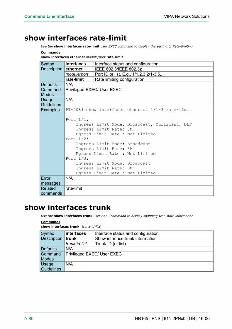
Command Line Interface VIPA Network Solutions
A-80 HB165 | PNS | 911-2PNx0 | GB | 16-06
show interfaces rate-limit Use the show interfaces rate-limit user EXEC command to display the setting of Rate-limiting.
Commands
show interfaces ethernet module/port rate-limit
Syntax Description
interfaces Interface status and configuration ethernet IEEE 802.3/IEEE 802.3z module/port Port ID or list. E.g., 1/1,2,3,2/1-3,5,... rate-limit Rate limiting configuration
Defaults N/A Command Modes
Privileged EXEC/ User EXEC
Usage Guidelines
N/A
Examples PT-508# show interfaces ethernet 1/1-3 rate-limit
Port 1/1:
Ingress Limit Mode: Broadcast, Multicast, DLF
Ingress Limit Rate: 8M
Egress Limit Rate : Not Limited
Port 1/2:
Ingress Limit Mode: Broadcast
Ingress Limit Rate: 8M
Egress Limit Rate : Not Limited
Port 1/3:
Ingress Limit Mode: Broadcast
Ingress Limit Rate: 8M
Egress Limit Rate : Not Limited
Error messages
N/A
Related commands
rate-limit
show interfaces trunk Use the show interfaces trunk user EXEC command to display spanning-tree state information
Commands
show interfaces trunk [trunk-id-list]
Syntax Description
interfaces Interface status and configuration trunk Show interface trunk information trunk-id-list Trunk ID (or list)
Defaults N/A Command Modes
Privileged EXEC/ User EXEC
Usage Guidelines
N/A
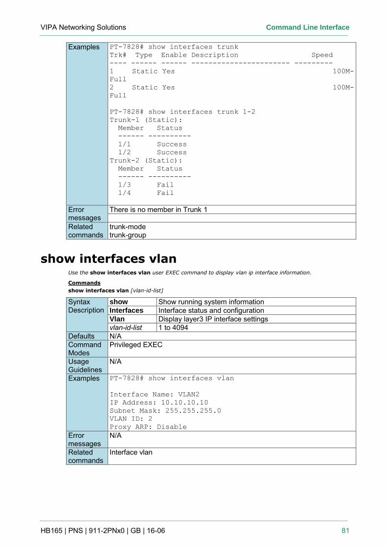
VIPA Networking Solutions Command Line Interface
HB165 | PNS | 911-2PNx0 | GB | 16-06 81
Examples PT-7828# show interfaces trunk
Trk# Type Enable Description Speed
---- ------ ------ ----------------------- ---------
1 Static Yes 100M-
Full
2 Static Yes 100M-
Full
PT-7828# show interfaces trunk 1-2
Trunk-1 (Static):
Member Status
------ ----------
1/1 Success
1/2 Success
Trunk-2 (Static):
Member Status
------ ----------
1/3 Fail
1/4 Fail
Error messages
There is no member in Trunk 1
Related commands
trunk-mode trunk-group
show interfaces vlan Use the show interfaces vlan user EXEC command to display vlan ip interface information.
Commands
show interfaces vlan [vlan-id-list]
Syntax Description
show Show running system information Interfaces Interface status and configuration Vlan Display layer3 IP interface settings vlan-id-list 1 to 4094
Defaults N/A Command Modes
Privileged EXEC
Usage Guidelines
N/A
Examples PT-7828# show interfaces vlan
Interface Name: VLAN2
IP Address: 10.10.10.10
Subnet Mask: 255.255.255.0
VLAN ID: 2
Proxy ARP: Disable
Error messages
N/A
Related commands
Interface vlan
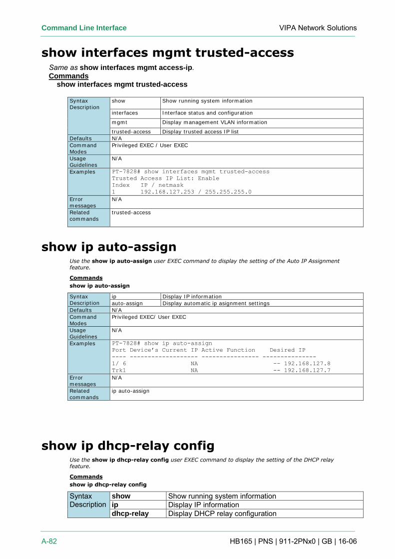
Command Line Interface VIPA Network Solutions
A-82 HB165 | PNS | 911-2PNx0 | GB | 16-06
show interfaces mgmt trusted-access Same as show interfaces mgmt access-ip. Commands
show interfaces mgmt trusted-access
Syntax Description
show Show running system information
interfaces Interface status and configuration
mgmt Display management VLAN information
trusted-access Display trusted access IP list
Defaults N/A
Command Modes
Privileged EXEC / User EXEC
Usage Guidelines
N/A
Examples PT-7828# show interfaces mgmt trusted-access
Trusted Access IP List: Enable
Index IP / netmask
1 192.168.127.253 / 255.255.255.0
Error messages
N/A
Related commands
trusted-access
show ip auto-assign Use the show ip auto-assign user EXEC command to display the setting of the Auto IP Assignment feature.
Commands
show ip auto-assign
Syntax Description
ip Display IP information
auto-assign Display automatic ip asignment settings
Defaults N/A
Command Modes
Privileged EXEC/ User EXEC
Usage Guidelines
N/A
Examples PT-7828# show ip auto-assign
Port Device’s Current IP Active Function Desired IP
---- ------------------- ---------------- ---------------
1/ 6 NA -- 192.168.127.8
Trk1 NA -- 192.168.127.7
Error messages
N/A
Related commands
ip auto-assign
show ip dhcp-relay config Use the show ip dhcp-relay config user EXEC command to display the setting of the DHCP relay feature.
Commands
show ip dhcp-relay config
Syntax Description
show Show running system information ip Display IP information dhcp-relay Display DHCP relay configuration
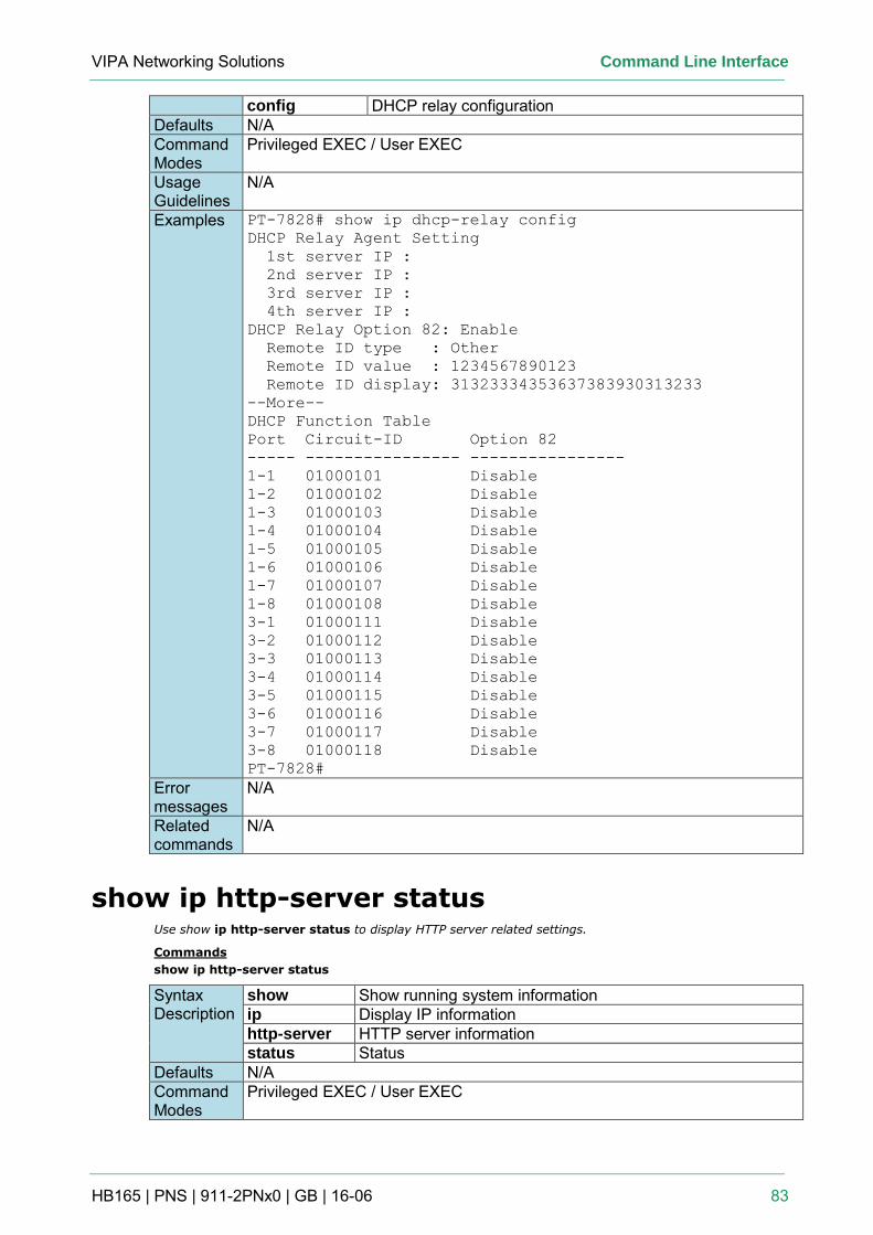
VIPA Networking Solutions Command Line Interface
HB165 | PNS | 911-2PNx0 | GB | 16-06 83
config DHCP relay configuration Defaults N/A Command Modes
Privileged EXEC / User EXEC
Usage Guidelines
N/A
Examples PT-7828# show ip dhcp-relay config
DHCP Relay Agent Setting
1st server IP :
2nd server IP :
3rd server IP :
4th server IP :
DHCP Relay Option 82: Enable
Remote ID type : Other
Remote ID value : 1234567890123
Remote ID display: 31323334353637383930313233
--More--
DHCP Function Table
Port Circuit-ID Option 82
----- ---------------- ----------------
1-1 01000101 Disable
1-2 01000102 Disable
1-3 01000103 Disable
1-4 01000104 Disable
1-5 01000105 Disable
1-6 01000106 Disable
1-7 01000107 Disable
1-8 01000108 Disable
3-1 01000111 Disable
3-2 01000112 Disable
3-3 01000113 Disable
3-4 01000114 Disable
3-5 01000115 Disable
3-6 01000116 Disable
3-7 01000117 Disable
3-8 01000118 Disable
PT-7828#
Error messages
N/A
Related commands
N/A
show ip http-server status Use show ip http-server status to display HTTP server related settings.
Commands
show ip http-server status
Syntax Description
show Show running system information ip Display IP information http-server HTTP server information status Status
Defaults N/A Command Modes
Privileged EXEC / User EXEC
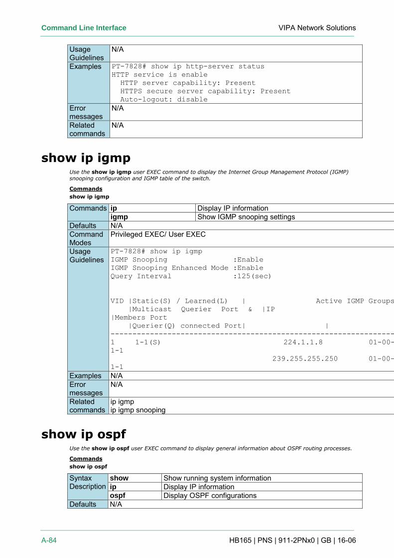
Command Line Interface VIPA Network Solutions
A-84 HB165 | PNS | 911-2PNx0 | GB | 16-06
Usage Guidelines
N/A
Examples PT-7828# show ip http-server status
HTTP service is enable
HTTP server capability: Present
HTTPS secure server capability: Present
Auto-logout: disable
Error messages
N/A
Related commands
N/A
show ip igmp Use the show ip igmp user EXEC command to display the Internet Group Management Protocol (IGMP) snooping configuration and IGMP table of the switch.
Commands
show ip igmp
Commands ip Display IP information igmp Show IGMP snooping settings
Defaults N/A Command Modes
Privileged EXEC/ User EXEC
Usage Guidelines
PT-7828# show ip igmp
IGMP Snooping :Enable
IGMP Snooping Enhanced Mode :Enable
Query Interval :125(sec)
VID |Static(S) / Learned(L) | Active IGMP Groups
|Multicast Querier Port & |IP |MAC
|Members Port
|Querier(Q) connected Port| | |
----------------------------------------------------------------------------
1 1-1(S) 224.1.1.8 01-00-5E-01-01-08
1-1
239.255.255.250 01-00-5E-7F-FF-FA
1-1
Examples N/A Error messages
N/A
Related commands
ip igmp ip igmp snooping
show ip ospf Use the show ip ospf user EXEC command to display general information about OSPF routing processes.
Commands
show ip ospf
Syntax Description
show Show running system information ip Display IP information ospf Display OSPF configurations
Defaults N/A
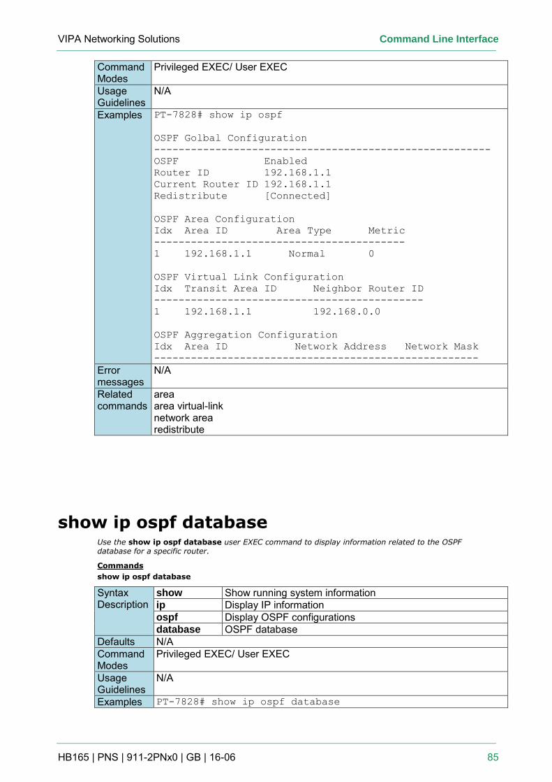
VIPA Networking Solutions Command Line Interface
HB165 | PNS | 911-2PNx0 | GB | 16-06 85
Command Modes
Privileged EXEC/ User EXEC
Usage Guidelines
N/A
Examples PT-7828# show ip ospf
OSPF Golbal Configuration
-------------------------------------------------------
OSPF Enabled
Router ID 192.168.1.1
Current Router ID 192.168.1.1
Redistribute [Connected]
OSPF Area Configuration
Idx Area ID Area Type Metric
-----------------------------------------
1 192.168.1.1 Normal 0
OSPF Virtual Link Configuration
Idx Transit Area ID Neighbor Router ID
--------------------------------------------
1 192.168.1.1 192.168.0.0
OSPF Aggregation Configuration
Idx Area ID Network Address Network Mask
-----------------------------------------------------
Error messages
N/A
Related commands
area area virtual-link network area redistribute
show ip ospf database Use the show ip ospf database user EXEC command to display information related to the OSPF database for a specific router.
Commands
show ip ospf database
Syntax Description
show Show running system information ip Display IP information ospf Display OSPF configurations database OSPF database
Defaults N/A Command Modes
Privileged EXEC/ User EXEC
Usage Guidelines
N/A
Examples PT-7828# show ip ospf database
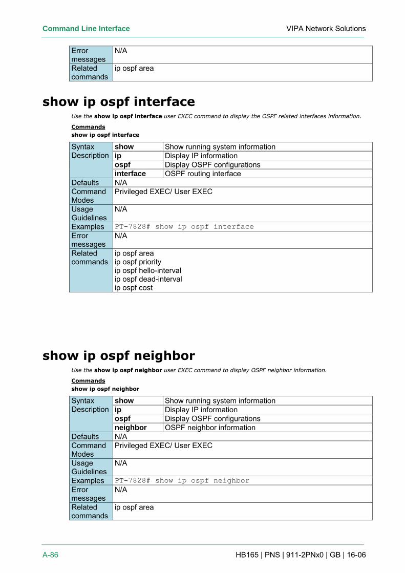
Command Line Interface VIPA Network Solutions
A-86 HB165 | PNS | 911-2PNx0 | GB | 16-06
Error messages
N/A
Related commands
ip ospf area
show ip ospf interface Use the show ip ospf interface user EXEC command to display the OSPF related interfaces information.
Commands
show ip ospf interface
Syntax Description
show Show running system information ip Display IP information ospf Display OSPF configurations interface OSPF routing interface
Defaults N/A Command Modes
Privileged EXEC/ User EXEC
Usage Guidelines
N/A
Examples PT-7828# show ip ospf interface
Error messages
N/A
Related commands
ip ospf area ip ospf priority ip ospf hello-interval ip ospf dead-interval ip ospf cost
show ip ospf neighbor Use the show ip ospf neighbor user EXEC command to display OSPF neighbor information.
Commands
show ip ospf neighbor
Syntax Description
show Show running system information ip Display IP information ospf Display OSPF configurations neighbor OSPF neighbor information
Defaults N/A Command Modes
Privileged EXEC/ User EXEC
Usage Guidelines
N/A
Examples PT-7828# show ip ospf neighbor
Error messages
N/A
Related commands
ip ospf area
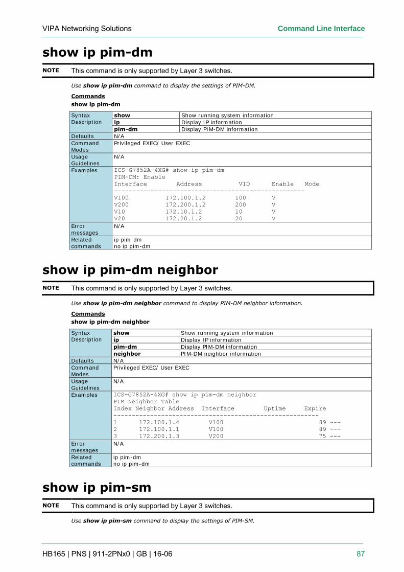
VIPA Networking Solutions Command Line Interface
HB165 | PNS | 911-2PNx0 | GB | 16-06 87
show ip pim-dm
NOTE This command is only supported by Layer 3 switches.
Use show ip pim-dm command to display the settings of PIM-DM.
Commands
show ip pim-dm
Syntax Description
show Show running system information
ip Display IP information
pim-dm Display PIM-DM information
Defaults N/A
Command Modes
Privileged EXEC/ User EXEC
Usage Guidelines
N/A
Examples ICS-G7852A-4XG# show ip pim-dm
PIM-DM: Enable
Interface Address VID Enable Mode
----------------------------------------------------
V100 172.100.1.2 100 V
V200 172.200.1.2 200 V
V10 172.10.1.2 10 V
V20 172.20.1.2 20 V
Error messages
N/A
Related commands
ip pim-dm no ip pim-dm
show ip pim-dm neighbor
NOTE This command is only supported by Layer 3 switches.
Use show ip pim-dm neighbor command to display PIM-DM neighbor information.
Commands
show ip pim-dm neighbor
Syntax Description
show Show running system information
ip Display IP information
pim-dm Display PIM-DM information
neighbor PIM-DM neighbor information
Defaults N/A
Command Modes
Privileged EXEC/ User EXEC
Usage Guidelines
N/A
Examples ICS-G7852A-4XG# show ip pim-dm neighbor
PIM Neighbor Table
Index Neighbor Address Interface Uptime Expire
--------------------------------------------------------
1 172.100.1.4 V100 89 ---
2 172.100.1.1 V100 89 ---
3 172.200.1.3 V200 75 ---
Error messages
N/A
Related commands
ip pim-dm no ip pim-dm
show ip pim-sm
NOTE This command is only supported by Layer 3 switches.
Use show ip pim-sm command to display the settings of PIM-SM.
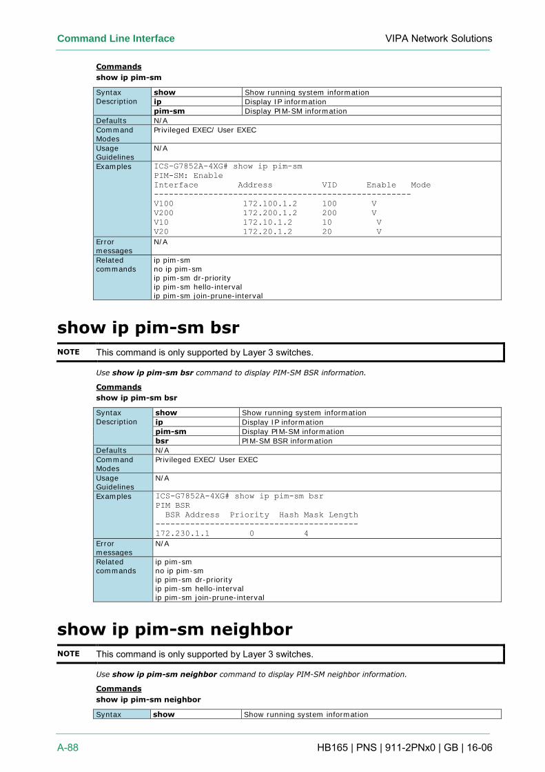
Command Line Interface VIPA Network Solutions
A-88 HB165 | PNS | 911-2PNx0 | GB | 16-06
Commands
show ip pim-sm
Syntax Description
show Show running system information
ip Display IP information
pim-sm Display PIM-SM information
Defaults N/A
Command Modes
Privileged EXEC/ User EXEC
Usage Guidelines
N/A
Examples ICS-G7852A-4XG# show ip pim-sm
PIM-SM: Enable
Interface Address VID Enable Mode
----------------------------------------------------
V100 172.100.1.2 100 V
V200 172.200.1.2 200 V
V10 172.10.1.2 10 V
V20 172.20.1.2 20 V
Error messages
N/A
Related commands
ip pim-sm no ip pim-sm ip pim-sm dr-priority ip pim-sm hello-interval ip pim-sm join-prune-interval
show ip pim-sm bsr
NOTE This command is only supported by Layer 3 switches.
Use show ip pim-sm bsr command to display PIM-SM BSR information.
Commands
show ip pim-sm bsr
Syntax
Description
show Show running system information
ip Display IP information
pim-sm Display PIM-SM information
bsr PIM-SM BSR information
Defaults N/A
Command Modes
Privileged EXEC/ User EXEC
Usage Guidelines
N/A
Examples ICS-G7852A-4XG# show ip pim-sm bsr
PIM BSR
BSR Address Priority Hash Mask Length
-----------------------------------------
172.230.1.1 0 4
Error messages
N/A
Related commands
ip pim-sm no ip pim-sm ip pim-sm dr-priority ip pim-sm hello-interval ip pim-sm join-prune-interval
show ip pim-sm neighbor
NOTE This command is only supported by Layer 3 switches.
Use show ip pim-sm neighbor command to display PIM-SM neighbor information.
Commands
show ip pim-sm neighbor
Syntax show Show running system information
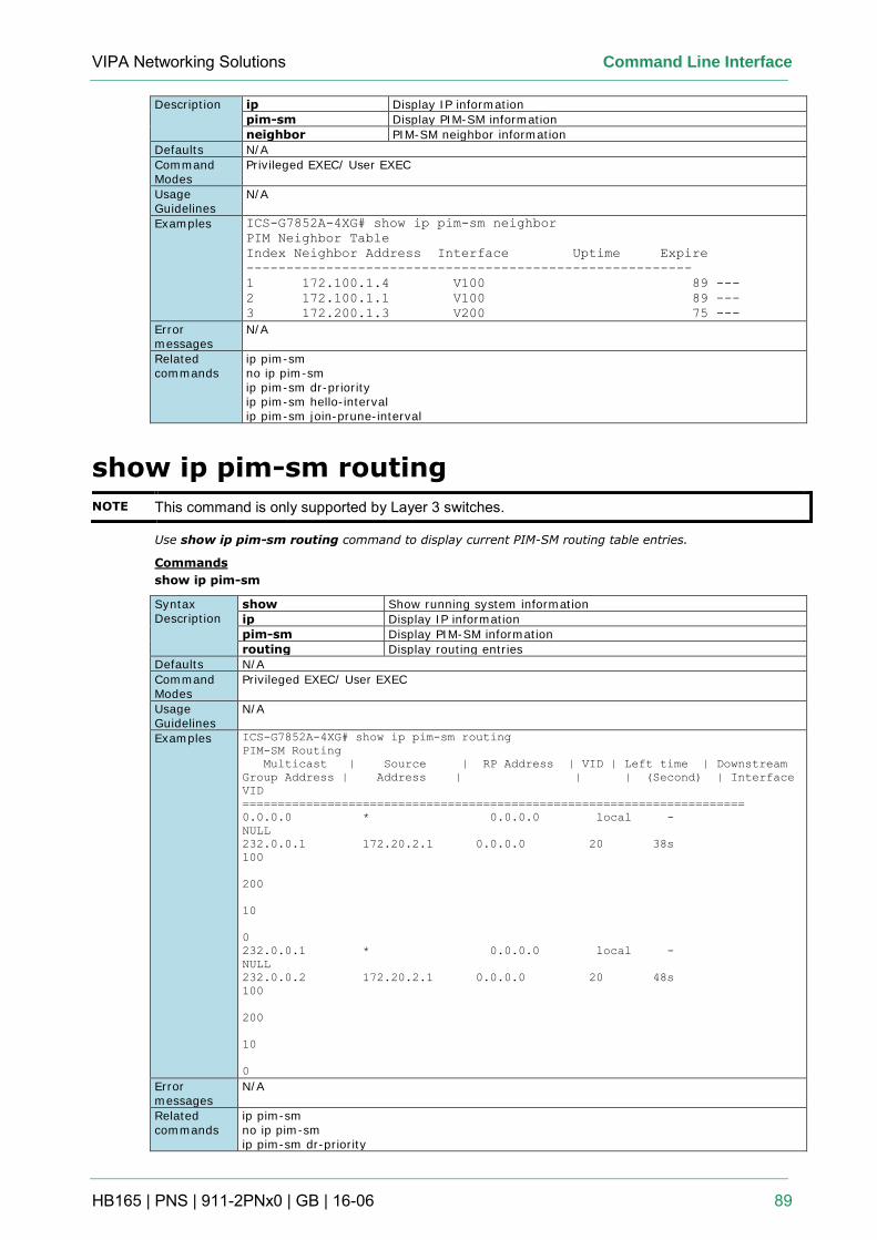
VIPA Networking Solutions Command Line Interface
HB165 | PNS | 911-2PNx0 | GB | 16-06 89
Description ip Display IP information
pim-sm Display PIM-SM information
neighbor PIM-SM neighbor information
Defaults N/A
Command Modes
Privileged EXEC/ User EXEC
Usage Guidelines
N/A
Examples ICS-G7852A-4XG# show ip pim-sm neighbor
PIM Neighbor Table
Index Neighbor Address Interface Uptime Expire
--------------------------------------------------------
1 172.100.1.4 V100 89 ---
2 172.100.1.1 V100 89 ---
3 172.200.1.3 V200 75 ---
Error messages
N/A
Related commands
ip pim-sm no ip pim-sm ip pim-sm dr-priority ip pim-sm hello-interval ip pim-sm join-prune-interval
show ip pim-sm routing
NOTE This command is only supported by Layer 3 switches.
Use show ip pim-sm routing command to display current PIM-SM routing table entries.
Commands
show ip pim-sm
Syntax Description
show Show running system information
ip Display IP information
pim-sm Display PIM-SM information
routing Display routing entries
Defaults N/A
Command Modes
Privileged EXEC/ User EXEC
Usage Guidelines
N/A
Examples ICS-G7852A-4XG# show ip pim-sm routing
PIM-SM Routing
Multicast | Source | RP Address | VID | Left time | Downstream
Group Address | Address | | | (Second) | Interface
VID
=======================================================================
0.0.0.0 * 0.0.0.0 local -
NULL
232.0.0.1 172.20.2.1 0.0.0.0 20 38s
100
200
10
0
232.0.0.1 * 0.0.0.0 local -
NULL
232.0.0.2 172.20.2.1 0.0.0.0 20 48s
100
200
10
0
Error messages
N/A
Related commands
ip pim-sm no ip pim-sm ip pim-sm dr-priority
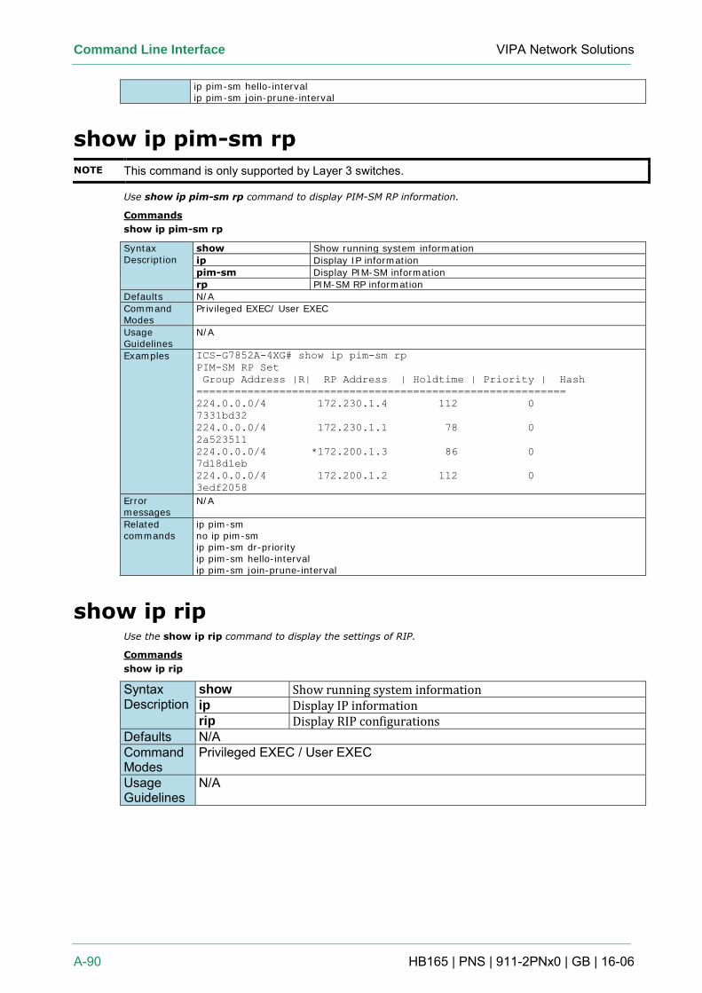
Command Line Interface VIPA Network Solutions
A-90 HB165 | PNS | 911-2PNx0 | GB | 16-06
ip pim-sm hello-interval ip pim-sm join-prune-interval
show ip pim-sm rp
NOTE This command is only supported by Layer 3 switches.
Use show ip pim-sm rp command to display PIM-SM RP information.
Commands
show ip pim-sm rp
Syntax Description
show Show running system information
ip Display IP information
pim-sm Display PIM-SM information
rp PIM-SM RP information
Defaults N/A
Command Modes
Privileged EXEC/ User EXEC
Usage Guidelines
N/A
Examples ICS-G7852A-4XG# show ip pim-sm rp
PIM-SM RP Set
Group Address |R| RP Address | Holdtime | Priority | Hash
==========================================================
224.0.0.0/4 172.230.1.4 112 0
7331bd32
224.0.0.0/4 172.230.1.1 78 0
2a523511
224.0.0.0/4 *172.200.1.3 86 0
7d18d1eb
224.0.0.0/4 172.200.1.2 112 0
3edf2058
Error messages
N/A
Related commands
ip pim-sm no ip pim-sm ip pim-sm dr-priority ip pim-sm hello-interval ip pim-sm join-prune-interval
show ip rip Use the show ip rip command to display the settings of RIP.
Commands
show ip rip
Syntax Description
show Show running system information ip Display IP information rip Display RIP configurations
Defaults N/A Command Modes
Privileged EXEC / User EXEC
Usage Guidelines
N/A
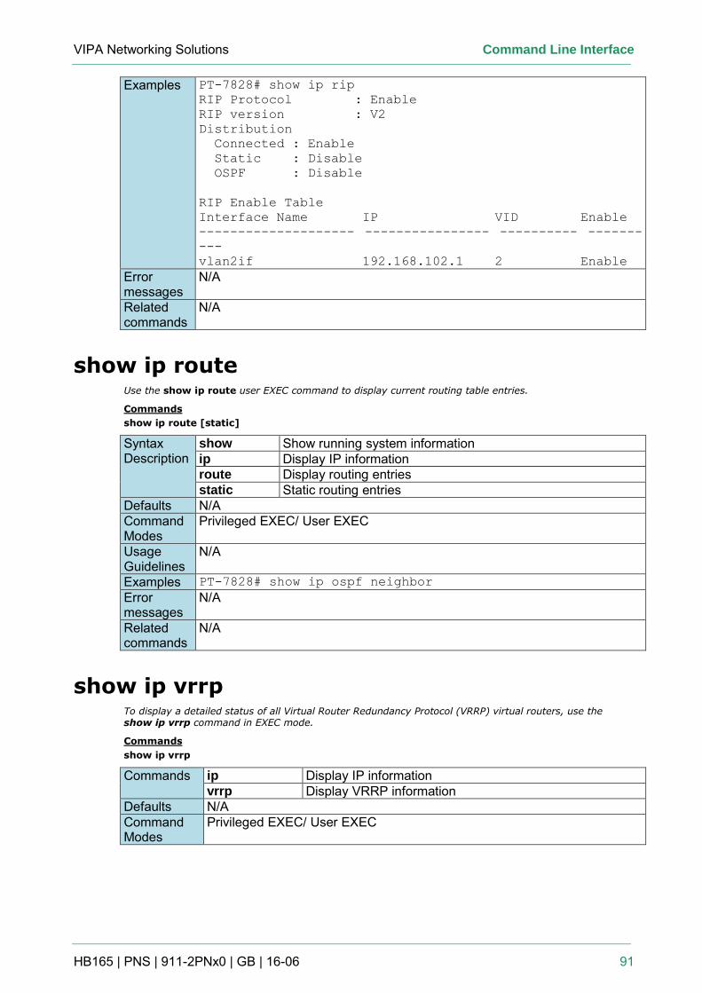
VIPA Networking Solutions Command Line Interface
HB165 | PNS | 911-2PNx0 | GB | 16-06 91
Examples PT-7828# show ip rip
RIP Protocol : Enable
RIP version : V2
Distribution
Connected : Enable
Static : Disable
OSPF : Disable
RIP Enable Table
Interface Name IP VID Enable
-------------------- ---------------- ---------- -------
---
vlan2if 192.168.102.1 2 Enable
Error messages
N/A
Related commands
N/A
show ip route Use the show ip route user EXEC command to display current routing table entries.
Commands
show ip route [static]
Syntax Description
show Show running system information ip Display IP information route Display routing entries static Static routing entries
Defaults N/A Command Modes
Privileged EXEC/ User EXEC
Usage Guidelines
N/A
Examples PT-7828# show ip ospf neighbor
Error messages
N/A
Related commands
N/A
show ip vrrp To display a detailed status of all Virtual Router Redundancy Protocol (VRRP) virtual routers, use the show ip vrrp command in EXEC mode.
Commands
show ip vrrp
Commands ip Display IP information vrrp Display VRRP information
Defaults N/A Command Modes
Privileged EXEC/ User EXEC
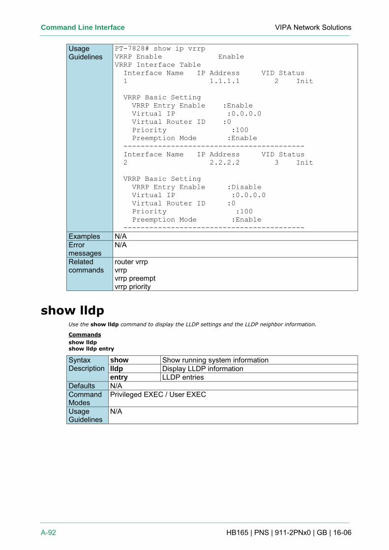
Command Line Interface VIPA Network Solutions
A-92 HB165 | PNS | 911-2PNx0 | GB | 16-06
Usage Guidelines
PT-7828# show ip vrrp
VRRP Enable Enable
VRRP Interface Table
Interface Name IP Address VID Status
1 1.1.1.1 2 Init
VRRP Basic Setting
VRRP Entry Enable :Enable
Virtual IP :0.0.0.0
Virtual Router ID :0
Priority :100
Preemption Mode :Enable
------------------------------------------
Interface Name IP Address VID Status
2 2.2.2.2 3 Init
VRRP Basic Setting
VRRP Entry Enable :Disable
Virtual IP :0.0.0.0
Virtual Router ID :0
Priority :100
Preemption Mode :Enable
------------------------------------------
Examples N/A Error messages
N/A
Related commands
router vrrp vrrp vrrp preempt vrrp priority
show lldp Use the show lldp command to display the LLDP settings and the LLDP neighbor information.
Commands
show lldp show lldp entry
Syntax Description
show Show running system information lldp Display LLDP information entry LLDP entries
Defaults N/A Command Modes
Privileged EXEC / User EXEC
Usage Guidelines
N/A
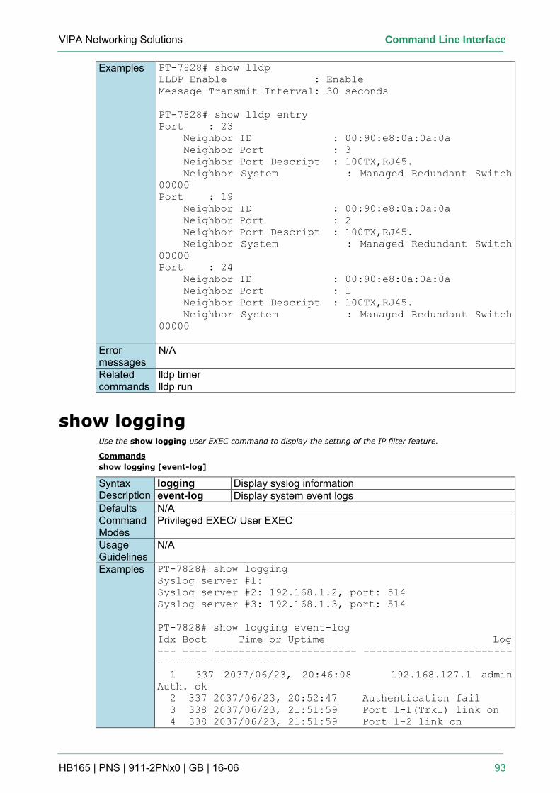
VIPA Networking Solutions Command Line Interface
HB165 | PNS | 911-2PNx0 | GB | 16-06 93
Examples PT-7828# show lldp
LLDP Enable : Enable
Message Transmit Interval: 30 seconds
PT-7828# show lldp entry
Port : 23
Neighbor ID : 00:90:e8:0a:0a:0a
Neighbor Port : 3
Neighbor Port Descript : 100TX,RJ45.
Neighbor System : Managed Redundant Switch
00000
Port : 19
Neighbor ID : 00:90:e8:0a:0a:0a
Neighbor Port : 2
Neighbor Port Descript : 100TX,RJ45.
Neighbor System : Managed Redundant Switch
00000
Port : 24
Neighbor ID : 00:90:e8:0a:0a:0a
Neighbor Port : 1
Neighbor Port Descript : 100TX,RJ45.
Neighbor System : Managed Redundant Switch
00000
Error messages
N/A
Related commands
lldp timer lldp run
show logging Use the show logging user EXEC command to display the setting of the IP filter feature.
Commands
show logging [event-log]
Syntax Description
logging Display syslog information event-log Display system event logs
Defaults N/A Command Modes
Privileged EXEC/ User EXEC
Usage Guidelines
N/A
Examples PT-7828# show logging
Syslog server #1:
Syslog server #2: 192.168.1.2, port: 514
Syslog server #3: 192.168.1.3, port: 514
PT-7828# show logging event-log
Idx Boot Time or Uptime Log
--- ---- ----------------------- ------------------------
--------------------
1 337 2037/06/23, 20:46:08 192.168.127.1 admin
Auth. ok
2 337 2037/06/23, 20:52:47 Authentication fail
3 338 2037/06/23, 21:51:59 Port 1-1(Trk1) link on
4 338 2037/06/23, 21:51:59 Port 1-2 link on
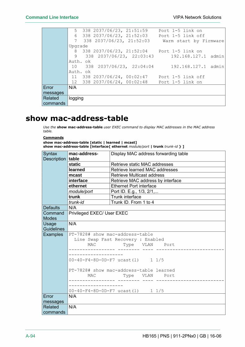
Command Line Interface VIPA Network Solutions
A-94 HB165 | PNS | 911-2PNx0 | GB | 16-06
5 338 2037/06/23, 21:51:59 Port 1-5 link on
6 338 2037/06/23, 21:52:03 Port 1-5 link off
7 338 2037/06/23, 21:52:03 Warm start by Firmware
Upgrade
8 338 2037/06/23, 21:52:04 Port 1-5 link on
9 338 2037/06/23, 22:03:43 192.168.127.1 admin
Auth. ok
10 338 2037/06/23, 22:04:04 192.168.127.1 admin
Auth. ok
11 338 2037/06/24, 00:02:47 Port 1-5 link off
12 338 2037/06/24, 00:02:48 Port 1-5 link on
Error messages
N/A
Related commands
logging
show mac-address-table Use the show mac-address-table user EXEC command to display MAC addresses in the MAC address table.
Commands
show mac-address-table [static | learned | mcast] show mac-address-table [interface{ ethernet module/port | trunk trunk-id } ]
Syntax Description
mac-address-table
Display MAC address forwarding table
static Retrieve static MAC addresses learned Retrieve learned MAC addresses mcast Retrieve Multicast address interface Retrieve MAC address by interface ethernet Ethernet Port interface module/port Port ID. E.g., 1/3, 2/1,... trunk Trunk interface trunk-id Trunk ID. From 1 to 4
Defaults N/A Command Modes
Privileged EXEC/ User EXEC
Usage Guidelines
N/A
Examples PT-7828# show mac-address-table
Line Swap Fast Recovery : Enabled
MAC Type VLAN Port
----------------- -------- ---- -------------------------
--------------------
00-40-F4-8D-0D-F7 ucast(l) 1 1/5
PT-7828# show mac-address-table learned
MAC Type VLAN Port
----------------- -------- ---- -------------------------
--------------------
00-40-F4-8D-0D-F7 ucast(l) 1 1/5
Error messages
N/A
Related commands
N/A
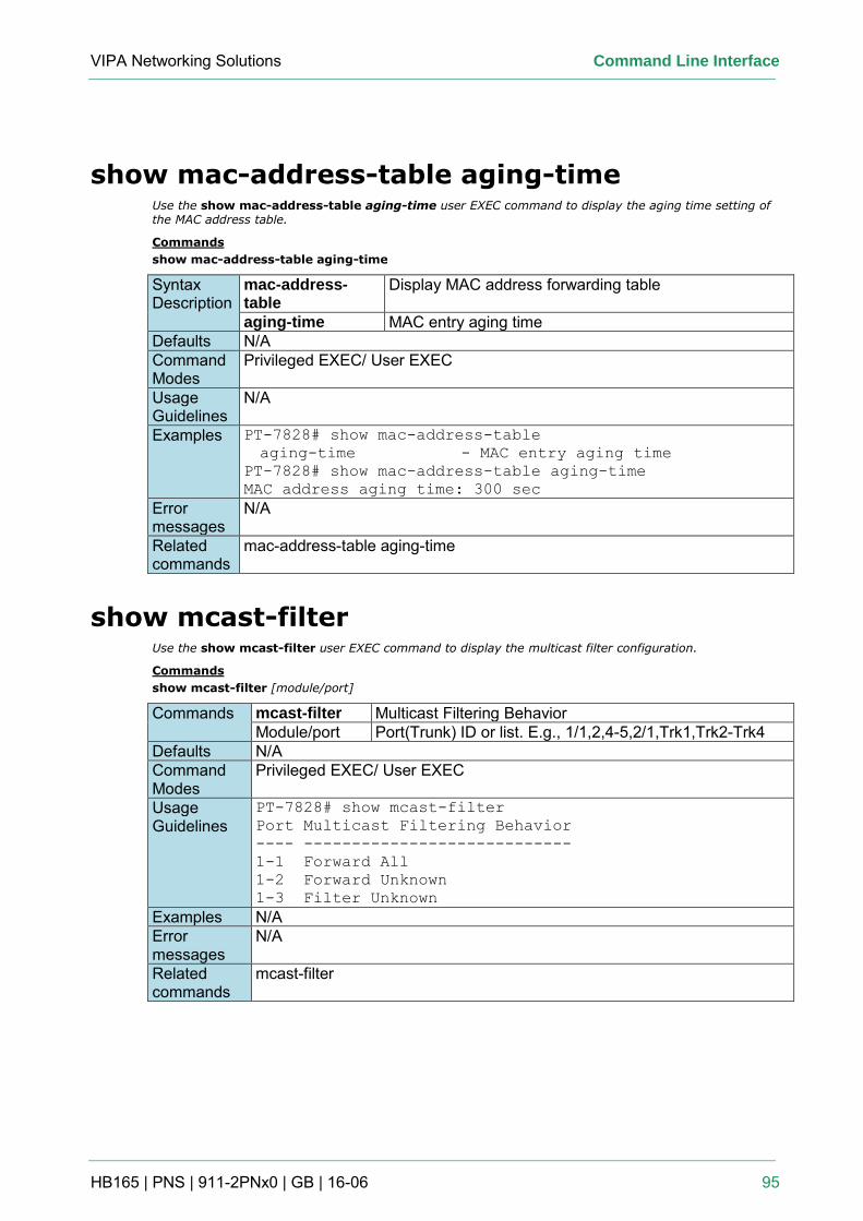
VIPA Networking Solutions Command Line Interface
HB165 | PNS | 911-2PNx0 | GB | 16-06 95
show mac-address-table aging-time Use the show mac-address-table aging-time user EXEC command to display the aging time setting of the MAC address table.
Commands
show mac-address-table aging-time
Syntax Description
mac-address-table
Display MAC address forwarding table
aging-time MAC entry aging time Defaults N/A Command Modes
Privileged EXEC/ User EXEC
Usage Guidelines
N/A
Examples PT-7828# show mac-address-table
aging-time - MAC entry aging time
PT-7828# show mac-address-table aging-time
MAC address aging time: 300 sec
Error messages
N/A
Related commands
mac-address-table aging-time
show mcast-filter Use the show mcast-filter user EXEC command to display the multicast filter configuration.
Commands
show mcast-filter [module/port]
Commands mcast-filter Multicast Filtering Behavior Module/port Port(Trunk) ID or list. E.g., 1/1,2,4-5,2/1,Trk1,Trk2-Trk4
Defaults N/A Command Modes
Privileged EXEC/ User EXEC
Usage Guidelines
PT-7828# show mcast-filter
Port Multicast Filtering Behavior
---- ----------------------------
1-1 Forward All
1-2 Forward Unknown
1-3 Filter Unknown
Examples N/A Error messages
N/A
Related commands
mcast-filter
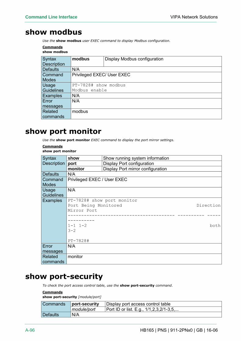
Command Line Interface VIPA Network Solutions
A-96 HB165 | PNS | 911-2PNx0 | GB | 16-06
show modbus Use the show modbus user EXEC command to display Modbus configuration.
Commands
show modbus
Syntax Description
modbus Display Modbus configuration
Defaults N/A Command Modes
Privileged EXEC/ User EXEC
Usage Guidelines
PT-7828# show modbus
Modbus enable
Examples N/A Error messages
N/A
Related commands
modbus
show port monitor Use the show port monitor EXEC command to display the port mirror settings.
Commands
show port monitor
Syntax Description
show Show running system information port Display Port configuration monitor Display Port mirror configuration
Defaults N/A Command Modes
Privileged EXEC / User EXEC
Usage Guidelines
N/A
Examples PT-7828# show port monitor
Port Being Monitored Direction
Mirror Port
---------------------------------------- ---------- -----
----------
1-1 1-2 both
3-2
PT-7828#
Error messages
N/A
Related commands
monitor
show port-security To check the port access control table, use the show port-security command.
Commands
show port-security [module/port]
Commands port-security Display port access control table module/port Port ID or list. E.g., 1/1,2,3,2/1-3,5,...
Defaults N/A
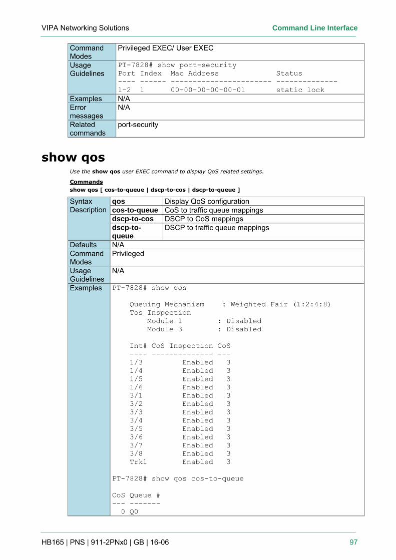
VIPA Networking Solutions Command Line Interface
HB165 | PNS | 911-2PNx0 | GB | 16-06 97
Command Modes
Privileged EXEC/ User EXEC
Usage Guidelines
PT-7828# show port-security
Port Index Mac Address Status
---- ------ ----------------------- --------------
1-2 1 00-00-00-00-00-01 static lock
Examples N/A Error messages
N/A
Related commands
port-security
show qos Use the show qos user EXEC command to display QoS related settings.
Commands
show qos [ cos-to-queue | dscp-to-cos | dscp-to-queue ]
Syntax Description
qos Display QoS configuration cos-to-queue CoS to traffic queue mappings dscp-to-cos DSCP to CoS mappings dscp-to-queue
DSCP to traffic queue mappings
Defaults N/A Command Modes
Privileged
Usage Guidelines
N/A
Examples PT-7828# show qos
Queuing Mechanism : Weighted Fair (1:2:4:8)
Tos Inspection
Module 1 : Disabled
Module 3 : Disabled
Int# CoS Inspection CoS
---- -------------- ---
1/3 Enabled 3
1/4 Enabled 3
1/5 Enabled 3
1/6 Enabled 3
3/1 Enabled 3
3/2 Enabled 3
3/3 Enabled 3
3/4 Enabled 3
3/5 Enabled 3
3/6 Enabled 3
3/7 Enabled 3
3/8 Enabled 3
Trk1 Enabled 3
PT-7828# show qos cos-to-queue
CoS Queue #
--- -------
0 Q0
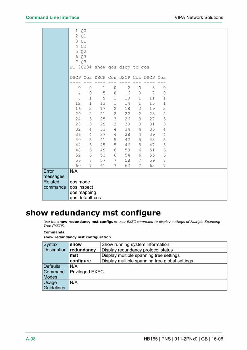
Command Line Interface VIPA Network Solutions
A-98 HB165 | PNS | 911-2PNx0 | GB | 16-06
1 Q0
2 Q1
3 Q1
4 Q2
5 Q2
6 Q3
7 Q3
PT-7828# show qos dscp-to-cos
DSCP Cos DSCP Cos DSCP Cos DSCP Cos
---- --- ---- --- ---- --- ---- ---
0 0 1 0 2 0 3 0
4 0 5 0 6 0 7 0
8 1 9 1 10 1 11 1
12 1 13 1 14 1 15 1
16 2 17 2 18 2 19 2
20 2 21 2 22 2 23 2
24 3 25 3 26 3 27 3
28 3 29 3 30 3 31 3
32 4 33 4 34 4 35 4
36 4 37 4 38 4 39 4
40 5 41 5 42 5 43 5
44 5 45 5 46 5 47 5
48 6 49 6 50 6 51 6
52 6 53 6 54 6 55 6
56 7 57 7 58 7 59 7
60 7 61 7 62 7 63 7
Error messages
N/A
Related commands
qos mode qos inspect qos mapping qos default-cos
show redundancy mst configure Use the show redundancy mst configure user EXEC command to display settings of Multiple Spanning Tree (MSTP).
Commands
show redundancy mst configuration
Syntax Description
show Show running system information redundancy Display redundancy protocol status mst Display multiple spanning tree settings configure Display multiple spanning tree global settings
Defaults N/A Command Modes
Privileged EXEC
Usage Guidelines
N/A
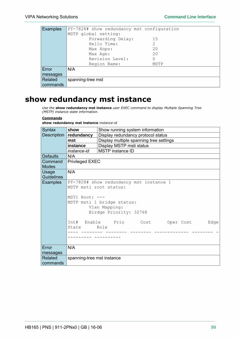
VIPA Networking Solutions Command Line Interface
HB165 | PNS | 911-2PNx0 | GB | 16-06 99
Examples PT-7828# show redundancy mst configuration
MSTP global setting:
Forwarding Delay: 15
Hello Time: 2
Max Hops: 20
Max Age: 20
Revision Level: 0
Region Name: MSTP
Error messages
N/A
Related commands
spanning-tree mst
show redundancy mst instance Use the show redundancy mst instance user EXEC command to display Multiple Spanning Tree (MSTP) instance state information.
Commands
show redundancy mst instance instance-id
Syntax Description
show Show running system information redundancy Display redundancy protocol status mst Display multiple spanning tree settings instance Display MSTP msti status instance-id MSTP instance ID
Defaults N/A Command Modes
Privileged EXEC
Usage Guidelines
N/A
Examples PT-7828# show redundancy mst instance 1
MSTP msti root status:
MSTI Root: ---
MSTP msti 1 bridge status:
Vlan Mapping:
Birdge Priority: 32768
Int# Enable Prio Cost Oper Cost Edge
State Role
---- -------- -------- -------- ------------- -------- -
--------- ----------
Error messages
N/A
Related commands
spanning-tree mst instance
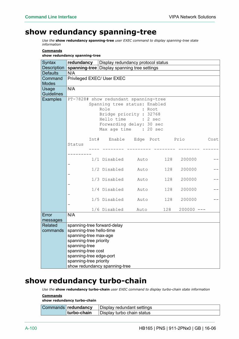
Command Line Interface VIPA Network Solutions
A-100 HB165 | PNS | 911-2PNx0 | GB | 16-06
show redundancy spanning-tree Use the show redundancy spanning-tree user EXEC command to display spanning-tree state information
Commands
show redundancy spanning-tree
Syntax Description
redundancy Display redundancy protocol status spanning-tree Display spanning tree settings
Defaults N/A Command Modes
Privileged EXEC/ User EXEC
Usage Guidelines
N/A
Examples PT-7828# show redundant spanning-tree
Spanning tree status: Enabled
Role : Root
Bridge priority : 32768
Hello time : 2 sec
Forwarding delay: 30 sec
Max age time : 20 sec
Int# Enable Edge Port Prio Cost
Status
---- -------- --------- -------- -------- ------
---------
1/1 Disabled Auto 128 200000 --
-
1/2 Disabled Auto 128 200000 --
-
1/3 Disabled Auto 128 200000 --
-
1/4 Disabled Auto 128 200000 --
-
1/5 Disabled Auto 128 200000 --
-
1/6 Disabled Auto 128 200000 ---
Error messages
N/A
Related commands
spanning-tree forward-delay spanning-tree hello-time spanning-tree max-age spanning-tree priority spanning-tree spanning-tree cost spanning-tree edge-port spanning-tree priority show redundancy spanning-tree
show redundancy turbo-chain Use the show redundancy turbo-chain user EXEC command to display turbo-chain state information
Commands
show redundancy turbo-chain
Commands redundancy Display redundant settings turbo-chain Display turbo chain status
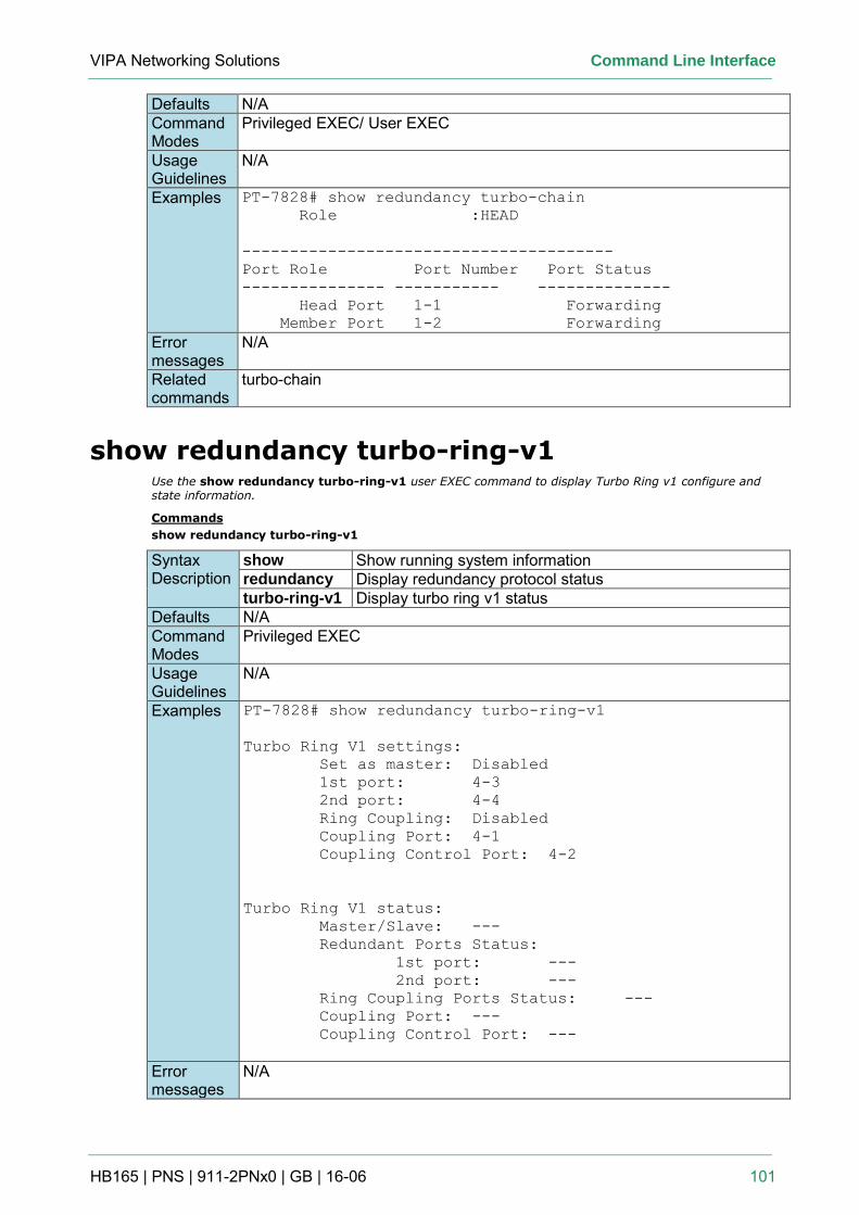
VIPA Networking Solutions Command Line Interface
HB165 | PNS | 911-2PNx0 | GB | 16-06 101
Defaults N/A Command Modes
Privileged EXEC/ User EXEC
Usage Guidelines
N/A
Examples PT-7828# show redundancy turbo-chain
Role :HEAD
---------------------------------------
Port Role Port Number Port Status
--------------- ----------- --------------
Head Port 1-1 Forwarding
Member Port 1-2 Forwarding
Error messages
N/A
Related commands
turbo-chain
show redundancy turbo-ring-v1 Use the show redundancy turbo-ring-v1 user EXEC command to display Turbo Ring v1 configure and state information.
Commands
show redundancy turbo-ring-v1
Syntax Description
show Show running system information redundancy Display redundancy protocol status turbo-ring-v1 Display turbo ring v1 status
Defaults N/A Command Modes
Privileged EXEC
Usage Guidelines
N/A
Examples PT-7828# show redundancy turbo-ring-v1
Turbo Ring V1 settings:
Set as master: Disabled
1st port: 4-3
2nd port: 4-4
Ring Coupling: Disabled
Coupling Port: 4-1
Coupling Control Port: 4-2
Turbo Ring V1 status:
Master/Slave: ---
Redundant Ports Status:
1st port: ---
2nd port: ---
Ring Coupling Ports Status: ---
Coupling Port: ---
Coupling Control Port: ---
Error messages
N/A
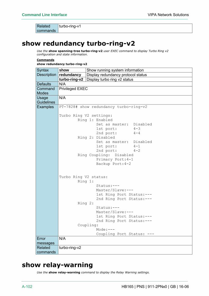
Command Line Interface VIPA Network Solutions
A-102 HB165 | PNS | 911-2PNx0 | GB | 16-06
Related commands
turbo-ring-v1
show redundancy turbo-ring-v2 Use the show spanning-tree turbo-ring-v2 user EXEC command to display Turbo Ring v2 configuration and state information.
Commands
show redundancy turbo-ring-v2
Syntax Description
show Show running system information redundancy Display redundancy protocol status turbo-ring-v2 Display turbo ring v2 status
Defaults N/A Command Modes
Privileged EXEC
Usage Guidelines
N/A
Examples PT-7828# show redundancy turbo-ring-v2
Turbo Ring V2 settings:
Ring 1: Enabled
Set as master: Disabled
1st port: 4-3
2nd port: 4-4
Ring 2: Disabled
Set as master: Disabled
1st port: 4-1
2nd port: 4-2
Ring Coupling: Disabled
Primary Port:4-1
Backup Port:4-2
Turbo Ring V2 status:
Ring 1:
Status:---
Master/Slave:---
1st Ring Port Status:---
2nd Ring Port Status:---
Ring 2:
Status:---
Master/Slave:---
1st Ring Port Status:---
2nd Ring Port Status:---
Coupling:
Mode:---
Coupling Port Status: ---
Error messages
N/A
Related commands
turbo-ring-v2
show relay-warning Use the show relay-warning command to display the Relay Warning settings.
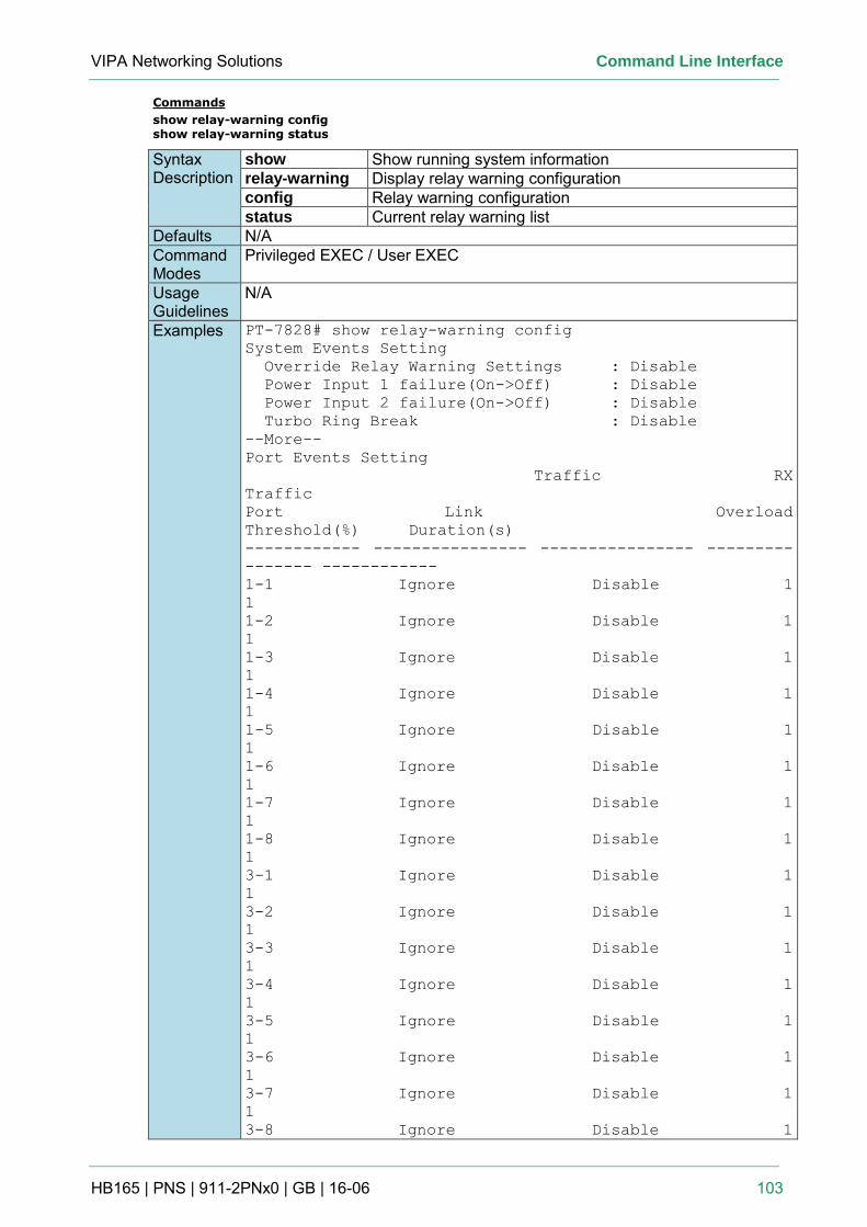
VIPA Networking Solutions Command Line Interface
HB165 | PNS | 911-2PNx0 | GB | 16-06 103
Commands
show relay-warning config show relay-warning status
Syntax Description
show Show running system information relay-warning Display relay warning configuration config Relay warning configuration status Current relay warning list
Defaults N/A Command Modes
Privileged EXEC / User EXEC
Usage Guidelines
N/A
Examples PT-7828# show relay-warning config
System Events Setting
Override Relay Warning Settings : Disable
Power Input 1 failure(On->Off) : Disable
Power Input 2 failure(On->Off) : Disable
Turbo Ring Break : Disable
--More--
Port Events Setting
Traffic RX
Traffic
Port Link Overload
Threshold(%) Duration(s)
------------ ---------------- ---------------- ---------
------- ------------
1-1 Ignore Disable 1
1
1-2 Ignore Disable 1
1
1-3 Ignore Disable 1
1
1-4 Ignore Disable 1
1
1-5 Ignore Disable 1
1
1-6 Ignore Disable 1
1
1-7 Ignore Disable 1
1
1-8 Ignore Disable 1
1
3-1 Ignore Disable 1
1
3-2 Ignore Disable 1
1
3-3 Ignore Disable 1
1
3-4 Ignore Disable 1
1
3-5 Ignore Disable 1
1
3-6 Ignore Disable 1
1
3-7 Ignore Disable 1
1
3-8 Ignore Disable 1
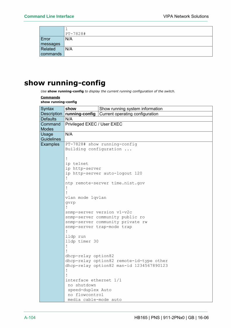
Command Line Interface VIPA Network Solutions
A-104 HB165 | PNS | 911-2PNx0 | GB | 16-06
1
PT-7828#
Error messages
N/A
Related commands
N/A
show running-config Use show running-config to display the current running configuration of the switch.
Commands
show running-config
Syntax Description
show Show running system information running-config Current operating configuration
Defaults N/A Command Modes
Privileged EXEC / User EXEC
Usage Guidelines
N/A
Examples PT-7828# show running-config
Building configuration ...
!
ip telnet
ip http-server
ip http-server auto-logout 120
!
ntp remote-server time.nist.gov
!
!
vlan mode 1qvlan
gvrp
!
snmp-server version v1-v2c
snmp-server community public ro
snmp-server community private rw
snmp-server trap-mode trap
!
lldp run
lldp timer 30
!
!
dhcp-relay option82
dhcp-relay option82 remote-id-type other
dhcp-relay option82 man-id 1234567890123
!
!
interface ethernet 1/1
no shutdown
speed-duplex Auto
no flowcontrol
media cable-mode auto
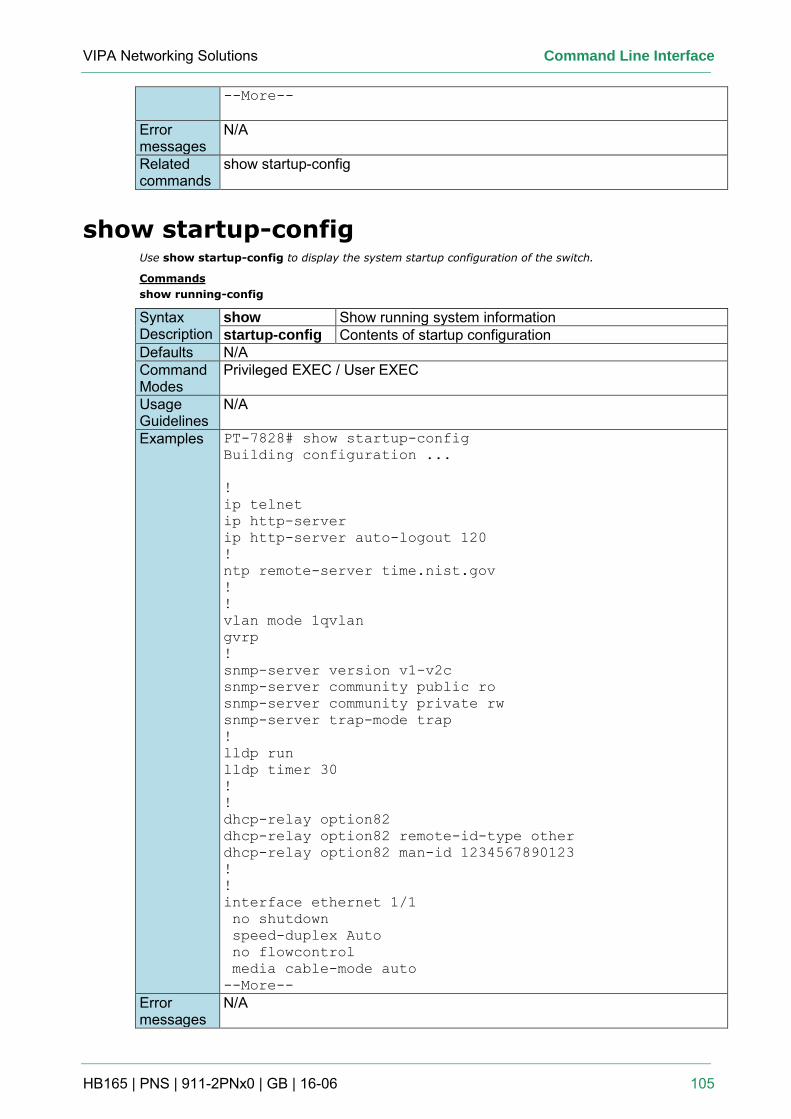
VIPA Networking Solutions Command Line Interface
HB165 | PNS | 911-2PNx0 | GB | 16-06 105
--More--
Error messages
N/A
Related commands
show startup-config
show startup-config Use show startup-config to display the system startup configuration of the switch.
Commands
show running-config
Syntax Description
show Show running system information startup-config Contents of startup configuration
Defaults N/A Command Modes
Privileged EXEC / User EXEC
Usage Guidelines
N/A
Examples PT-7828# show startup-config
Building configuration ...
!
ip telnet
ip http-server
ip http-server auto-logout 120
!
ntp remote-server time.nist.gov
!
!
vlan mode 1qvlan
gvrp
!
snmp-server version v1-v2c
snmp-server community public ro
snmp-server community private rw
snmp-server trap-mode trap
!
lldp run
lldp timer 30
!
!
dhcp-relay option82
dhcp-relay option82 remote-id-type other
dhcp-relay option82 man-id 1234567890123
!
!
interface ethernet 1/1
no shutdown
speed-duplex Auto
no flowcontrol
media cable-mode auto
--More--
Error messages
N/A
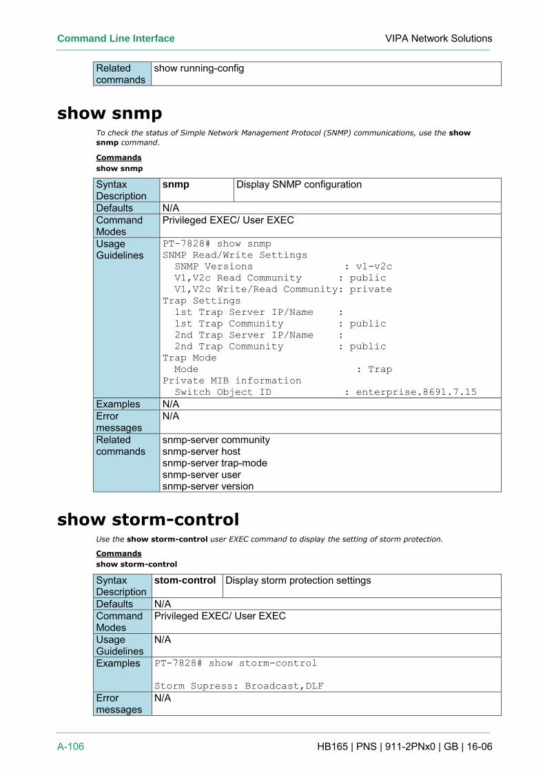
Command Line Interface VIPA Network Solutions
A-106 HB165 | PNS | 911-2PNx0 | GB | 16-06
Related commands
show running-config
show snmp To check the status of Simple Network Management Protocol (SNMP) communications, use the show
snmp command.
Commands
show snmp
Syntax Description
snmp Display SNMP configuration
Defaults N/A Command Modes
Privileged EXEC/ User EXEC
Usage Guidelines
PT-7828# show snmp
SNMP Read/Write Settings
SNMP Versions : v1-v2c
V1,V2c Read Community : public
V1,V2c Write/Read Community: private
Trap Settings
1st Trap Server IP/Name :
1st Trap Community : public
2nd Trap Server IP/Name :
2nd Trap Community : public
Trap Mode
Mode : Trap
Private MIB information
Switch Object ID : enterprise.8691.7.15
Examples N/A Error messages
N/A
Related commands
snmp-server community snmp-server host snmp-server trap-mode snmp-server user snmp-server version
show storm-control Use the show storm-control user EXEC command to display the setting of storm protection.
Commands
show storm-control
Syntax Description
stom-control Display storm protection settings
Defaults N/A Command Modes
Privileged EXEC/ User EXEC
Usage Guidelines
N/A
Examples PT-7828# show storm-control
Storm Supress: Broadcast,DLF
Error messages
N/A
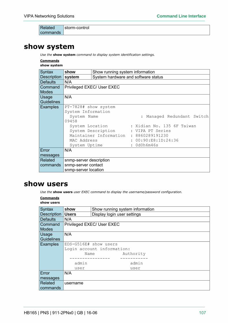
VIPA Networking Solutions Command Line Interface
HB165 | PNS | 911-2PNx0 | GB | 16-06 107
Related commands
storm-control
show system Use the show system command to display system identification settings.
Commands
show system
Syntax Description
show Show running system information system System hardware and software status
Defaults N/A Command Modes
Privileged EXEC/ User EXEC
Usage Guidelines
N/A
Examples PT-7828# show system
System Information
System Name : Managed Redundant Switch
09458
System Location : Xidian No. 135 6F Taiwan
System Description : VIPA PT Series
Maintainer Information : 8860289191230
MAC Address : 00:90:E8:1D:24:36
System Uptime : 0d0h6m46s
Error messages
N/A
Related commands
snmp-server description snmp-server contact snmp-server location
show users Use the show users user EXEC command to display the username/password configuration.
Commands
show users
Syntax Description
show Show running system information Users Display login user settings
Defaults N/A Command Modes
Privileged EXEC/ User EXEC
Usage Guidelines
N/A
Examples EDS-G516E# show users
Login account information:
Name Authority
---------------- -----------
admin admin
user user
Error messages
N/A
Related commands
username
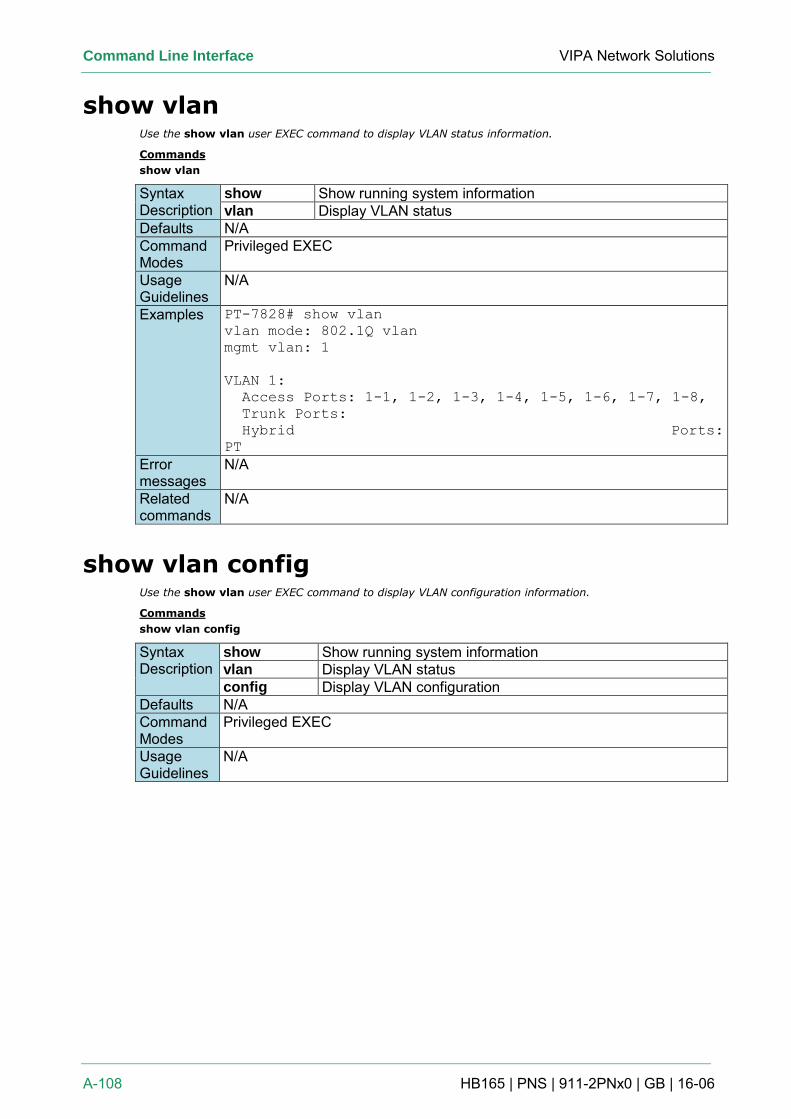
Command Line Interface VIPA Network Solutions
A-108 HB165 | PNS | 911-2PNx0 | GB | 16-06
show vlan Use the show vlan user EXEC command to display VLAN status information.
Commands
show vlan
Syntax Description
show Show running system information vlan Display VLAN status
Defaults N/A Command Modes
Privileged EXEC
Usage Guidelines
N/A
Examples PT-7828# show vlan
vlan mode: 802.1Q vlan
mgmt vlan: 1
VLAN 1:
Access Ports: 1-1, 1-2, 1-3, 1-4, 1-5, 1-6, 1-7, 1-8,
Trunk Ports:
Hybrid Ports:
PT
Error messages
N/A
Related commands
N/A
show vlan config Use the show vlan user EXEC command to display VLAN configuration information.
Commands
show vlan config
Syntax Description
show Show running system information vlan Display VLAN status config Display VLAN configuration
Defaults N/A Command Modes
Privileged EXEC
Usage Guidelines
N/A
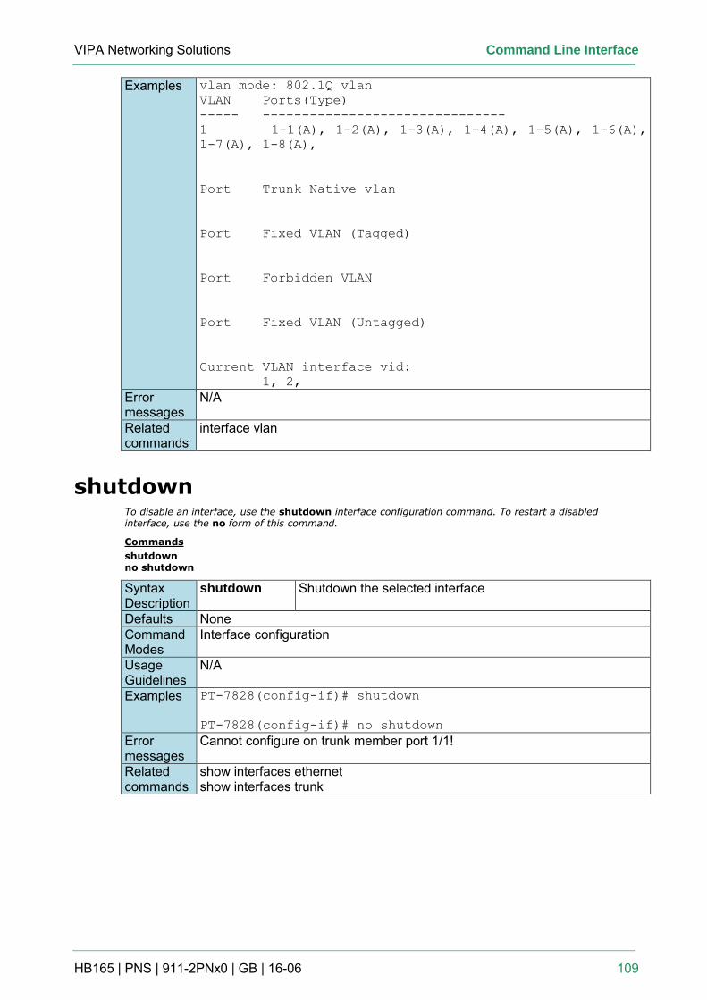
VIPA Networking Solutions Command Line Interface
HB165 | PNS | 911-2PNx0 | GB | 16-06 109
Examples vlan mode: 802.1Q vlan
VLAN Ports(Type)
----- -------------------------------
1 1-1(A), 1-2(A), 1-3(A), 1-4(A), 1-5(A), 1-6(A),
1-7(A), 1-8(A),
Port Trunk Native vlan
Port Fixed VLAN (Tagged)
Port Forbidden VLAN
Port Fixed VLAN (Untagged)
Current VLAN interface vid:
1, 2,
Error messages
N/A
Related commands
interface vlan
shutdown To disable an interface, use the shutdown interface configuration command. To restart a disabled interface, use the no form of this command.
Commands
shutdown no shutdown
Syntax Description
shutdown Shutdown the selected interface
Defaults None Command Modes
Interface configuration
Usage Guidelines
N/A
Examples PT-7828(config-if)# shutdown
PT-7828(config-if)# no shutdown
Error messages
Cannot configure on trunk member port 1/1!
Related commands
show interfaces ethernet show interfaces trunk
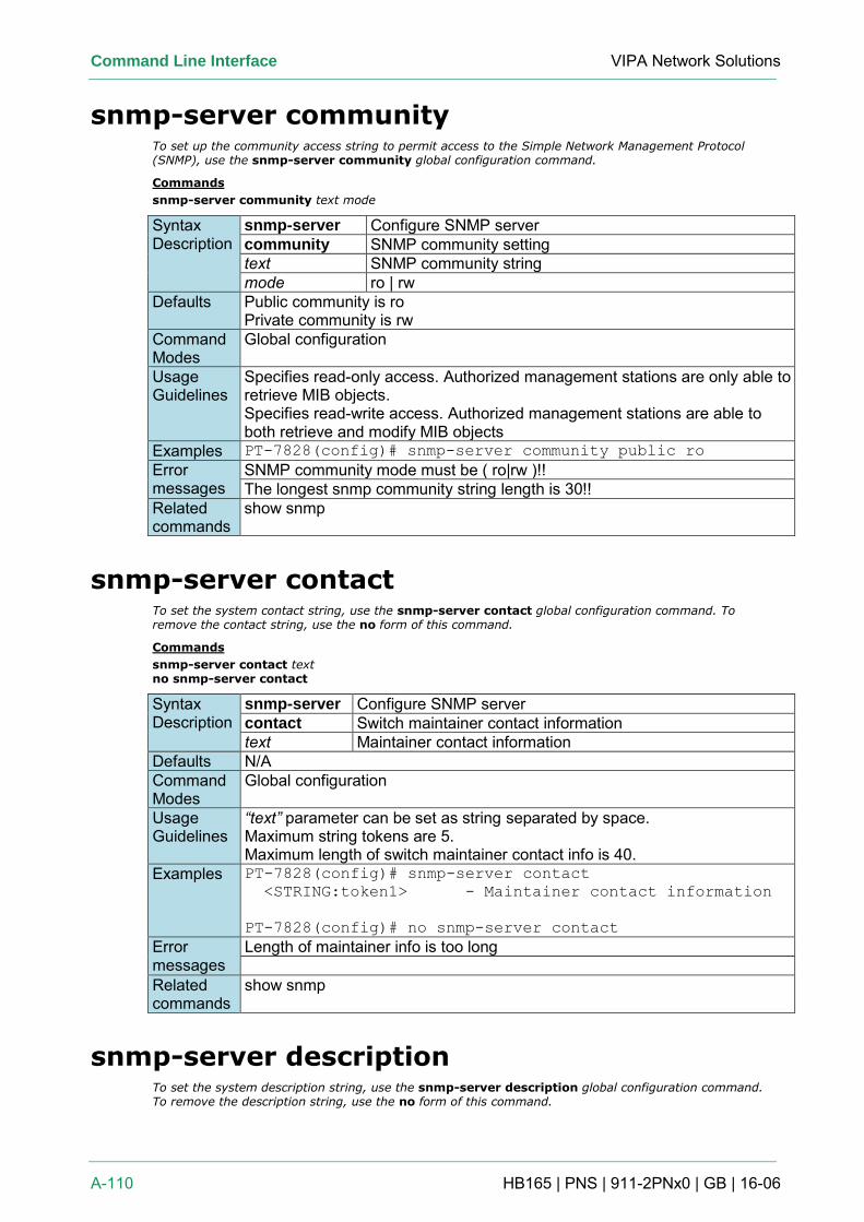
Command Line Interface VIPA Network Solutions
A-110 HB165 | PNS | 911-2PNx0 | GB | 16-06
snmp-server community To set up the community access string to permit access to the Simple Network Management Protocol (SNMP), use the snmp-server community global configuration command.
Commands
snmp-server community text mode
Syntax Description
snmp-server Configure SNMP server community SNMP community setting text SNMP community string mode ro | rw
Defaults Public community is ro Private community is rw
Command Modes
Global configuration
Usage Guidelines
Specifies read-only access. Authorized management stations are only able to retrieve MIB objects. Specifies read-write access. Authorized management stations are able to both retrieve and modify MIB objects
Examples PT-7828(config)# snmp-server community public ro
Error messages
SNMP community mode must be ( ro|rw )!! The longest snmp community string length is 30!!
Related commands
show snmp
snmp-server contact To set the system contact string, use the snmp-server contact global configuration command. To remove the contact string, use the no form of this command.
Commands
snmp-server contact text no snmp-server contact
Syntax Description
snmp-server Configure SNMP server contact Switch maintainer contact information text Maintainer contact information
Defaults N/A Command Modes
Global configuration
Usage Guidelines
“text” parameter can be set as string separated by space. Maximum string tokens are 5. Maximum length of switch maintainer contact info is 40.
Examples PT-7828(config)# snmp-server contact
<STRING:token1> - Maintainer contact information
PT-7828(config)# no snmp-server contact
Error messages
Length of maintainer info is too long
Related commands
show snmp
snmp-server description To set the system description string, use the snmp-server description global configuration command. To remove the description string, use the no form of this command.
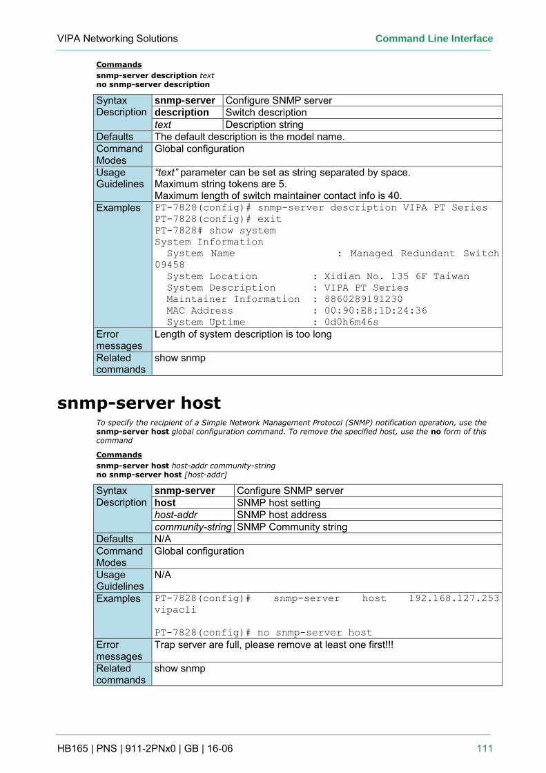
VIPA Networking Solutions Command Line Interface
HB165 | PNS | 911-2PNx0 | GB | 16-06 111
Commands
snmp-server description text no snmp-server description
Syntax Description
snmp-server Configure SNMP server description Switch description text Description string
Defaults The default description is the model name. Command Modes
Global configuration
Usage Guidelines
“text” parameter can be set as string separated by space. Maximum string tokens are 5. Maximum length of switch maintainer contact info is 40.
Examples PT-7828(config)# snmp-server description VIPA PT Series
PT-7828(config)# exit
PT-7828# show system
System Information
System Name : Managed Redundant Switch
09458
System Location : Xidian No. 135 6F Taiwan
System Description : VIPA PT Series
Maintainer Information : 8860289191230
MAC Address : 00:90:E8:1D:24:36
System Uptime : 0d0h6m46s
Error messages
Length of system description is too long
Related commands
show snmp
snmp-server host To specify the recipient of a Simple Network Management Protocol (SNMP) notification operation, use the snmp-server host global configuration command. To remove the specified host, use the no form of this command
Commands
snmp-server host host-addr community-string no snmp-server host [host-addr]
Syntax Description
snmp-server Configure SNMP server host SNMP host setting host-addr SNMP host address community-string SNMP Community string
Defaults N/A Command Modes
Global configuration
Usage Guidelines
N/A
Examples PT-7828(config)# snmp-server host 192.168.127.253
vipacli
PT-7828(config)# no snmp-server host
Error messages
Trap server are full, please remove at least one first!!!
Related commands
show snmp
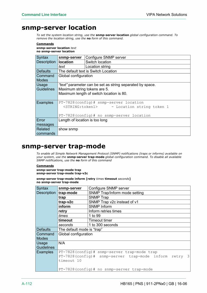
Command Line Interface VIPA Network Solutions
A-112 HB165 | PNS | 911-2PNx0 | GB | 16-06
snmp-server location To set the system location string, use the snmp-server location global configuration command. To remove the location string, use the no form of this command.
Commands
snmp-server location text no snmp-server location
Syntax Description
snmp-server Configure SNMP server location Switch location text Location string
Defaults The default text is Switch Location Command Modes
Global configuration
Usage Guidelines
“text” parameter can be set as string separated by space. Maximum string tokens are 5. Maximum length of switch location is 80.
Examples PT-7828(config)# snmp-server location
<STRING:token1> - Location string token 1
PT-7828(config)# no snmp-server location
Error messages
Length of location is too long
Related commands
show snmp
snmp-server trap-mode To enable all Simple Network Management Protocol (SNMP) notifications (traps or informs) available on your system, use the snmp-server trap-mode global configuration command. To disable all available SNMP notifications, use the no form of this command
Commands
snmp-server trap-mode trap snmp-server trap-mode trap-v2c
snmp-server trap-mode inform [retry times timeout seconds] no snmp-server trap-mode
Syntax Description
snmp-server Configure SNMP server trap-mode SNMP Trap/Inform mode setting trap SNMP Trap trap-v2c SNMP Trap v2c instead of v1 inform SNMP Inform retry Inform retries times times 1 to 99 timeout Timeout timer seconds 1 to 300 seconds
Defaults The default mode is “trap” Command Modes
Global configuration
Usage Guidelines
N/A
Examples PT-7828(config)# snmp-server trap-mode trap
PT-7828(config)# snmp-server trap-mode inform retry 3
timeout 10
PT-7828(config)# no snmp-server trap-mode
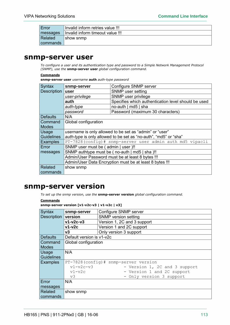
VIPA Networking Solutions Command Line Interface
HB165 | PNS | 911-2PNx0 | GB | 16-06 113
Error messages
Invalid inform retries value !!! Invalid inform timeout value !!!
Related commands
show snmp
snmp-server user To configure a user and its authentication type and password to a Simple Network Management Protocol
(SNMP), use the snmp-server user global configuration command.
Commands
snmp-server user username auth auth-type password
Syntax Description
snmp-server Configure SNMP server user SNMP user setting user-privilege SNMP user privilege auth Specifies which authentication level should be used auth-type no-auth | md5 | sha password Password (maximum 30 characters)
Defaults N/A Command Modes
Global configuration
Usage Guidelines
username is only allowed to be set as “admin” or “user” auth-type is only allowed to be set as “no-auth”, “md5” or “sha”
Examples PT-7828(config)# snmp-server user admin auth md5 vipacli
Error messages
SNMP user must be ( admin | user )!! SNMP authtype must be ( no-auth | md5 | sha )!! Admin/User Password must be at least 8 bytes !!! Admin/User Data Encryption must be at least 8 bytes !!!
Related commands
show snmp
snmp-server version To set up the snmp version, use the snmp-server version global configuration command.
Commands
snmp-server version [v1-v2c-v3 | v1-v2c | v3]
Syntax Description
snmp-server Configure SNMP server version SNMP version setting v1-v2c-v3 Version 1, 2C and 3 support v1-v2c Version 1 and 2C support v3 Only version 3 support
Defaults Default version is v1-v2c Command Modes
Global configuration
Usage Guidelines
N/A
Examples PT-7828(config)# snmp-server version
v1-v2c-v3 - Version 1, 2C and 3 support
v1-v2c - Version 1 and 2C support
v3 - Only version 3 support
Error messages
N/A
Related commands
show snmp
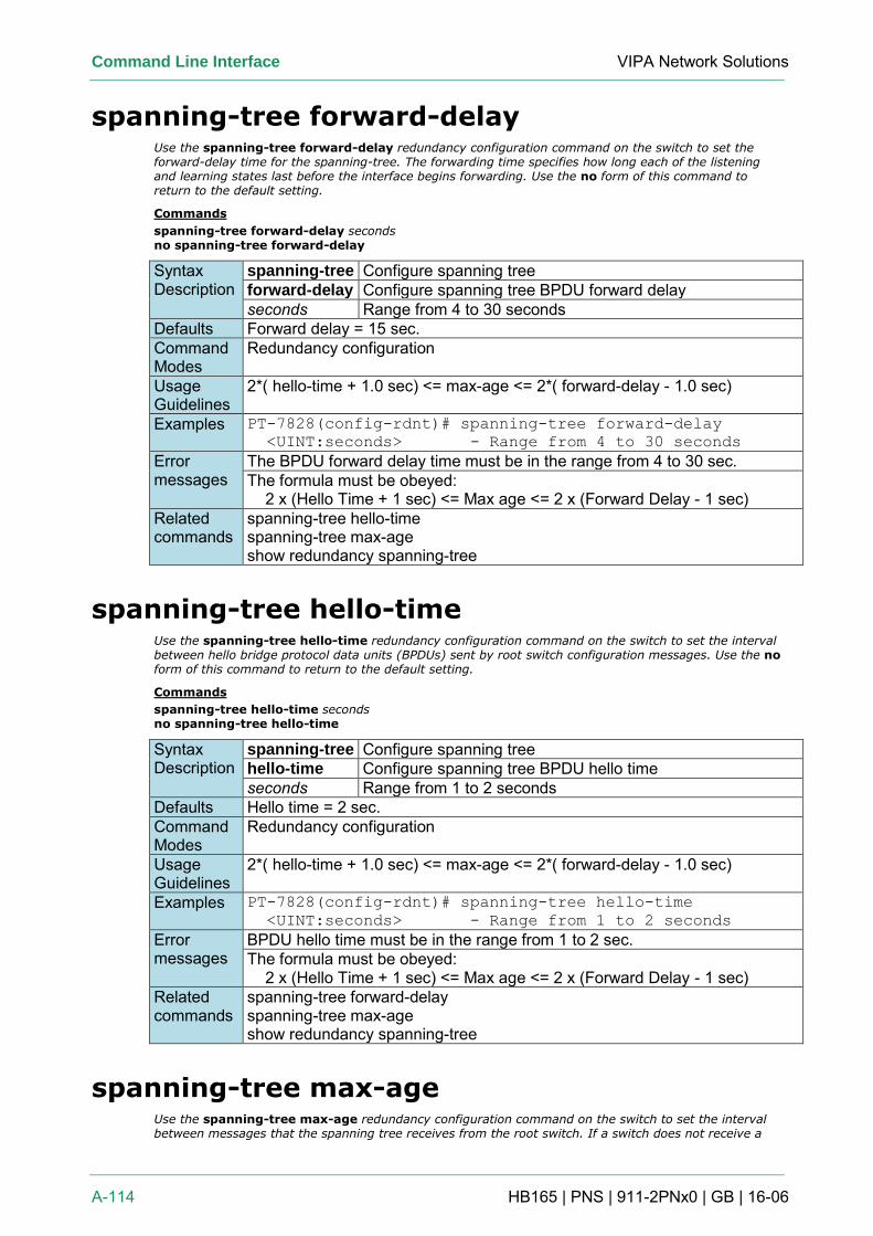
Command Line Interface VIPA Network Solutions
A-114 HB165 | PNS | 911-2PNx0 | GB | 16-06
spanning-tree forward-delay Use the spanning-tree forward-delay redundancy configuration command on the switch to set the forward-delay time for the spanning-tree. The forwarding time specifies how long each of the listening and learning states last before the interface begins forwarding. Use the no form of this command to return to the default setting.
Commands
spanning-tree forward-delay seconds no spanning-tree forward-delay
Syntax Description
spanning-tree Configure spanning tree forward-delay Configure spanning tree BPDU forward delay seconds Range from 4 to 30 seconds
Defaults Forward delay = 15 sec. Command Modes
Redundancy configuration
Usage Guidelines
2*( hello-time + 1.0 sec) <= max-age <= 2*( forward-delay - 1.0 sec)
Examples PT-7828(config-rdnt)# spanning-tree forward-delay
<UINT:seconds> - Range from 4 to 30 seconds
Error messages
The BPDU forward delay time must be in the range from 4 to 30 sec. The formula must be obeyed: 2 x (Hello Time + 1 sec) <= Max age <= 2 x (Forward Delay - 1 sec)
Related commands
spanning-tree hello-time spanning-tree max-age show redundancy spanning-tree
spanning-tree hello-time Use the spanning-tree hello-time redundancy configuration command on the switch to set the interval between hello bridge protocol data units (BPDUs) sent by root switch configuration messages. Use the no form of this command to return to the default setting.
Commands
spanning-tree hello-time seconds no spanning-tree hello-time
Syntax Description
spanning-tree Configure spanning tree hello-time Configure spanning tree BPDU hello time seconds Range from 1 to 2 seconds
Defaults Hello time = 2 sec. Command Modes
Redundancy configuration
Usage Guidelines
2*( hello-time + 1.0 sec) <= max-age <= 2*( forward-delay - 1.0 sec)
Examples PT-7828(config-rdnt)# spanning-tree hello-time
<UINT:seconds> - Range from 1 to 2 seconds
Error messages
BPDU hello time must be in the range from 1 to 2 sec. The formula must be obeyed: 2 x (Hello Time + 1 sec) <= Max age <= 2 x (Forward Delay - 1 sec)
Related commands
spanning-tree forward-delay spanning-tree max-age show redundancy spanning-tree
spanning-tree max-age Use the spanning-tree max-age redundancy configuration command on the switch to set the interval between messages that the spanning tree receives from the root switch. If a switch does not receive a
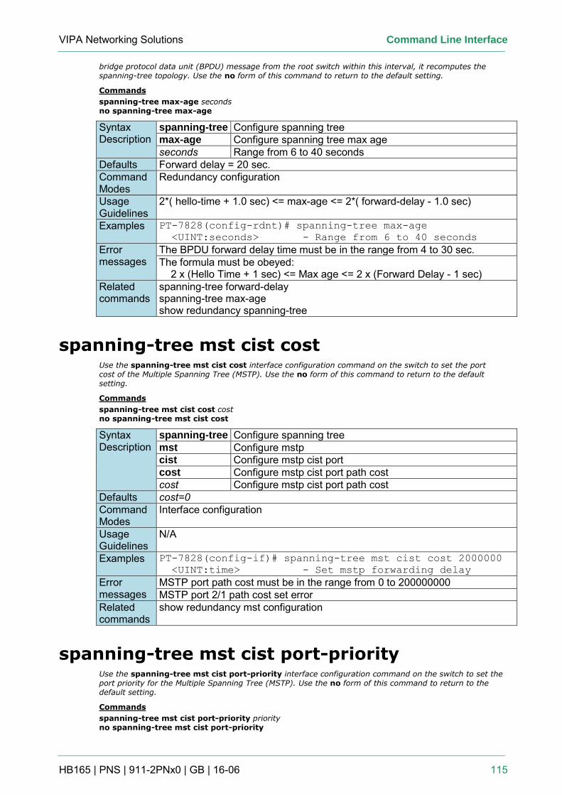
VIPA Networking Solutions Command Line Interface
HB165 | PNS | 911-2PNx0 | GB | 16-06 115
bridge protocol data unit (BPDU) message from the root switch within this interval, it recomputes the spanning-tree topology. Use the no form of this command to return to the default setting.
Commands
spanning-tree max-age seconds no spanning-tree max-age
Syntax Description
spanning-tree Configure spanning tree max-age Configure spanning tree max age seconds Range from 6 to 40 seconds
Defaults Forward delay = 20 sec. Command Modes
Redundancy configuration
Usage Guidelines
2*( hello-time + 1.0 sec) <= max-age <= 2*( forward-delay - 1.0 sec)
Examples PT-7828(config-rdnt)# spanning-tree max-age
<UINT:seconds> - Range from 6 to 40 seconds
Error messages
The BPDU forward delay time must be in the range from 4 to 30 sec. The formula must be obeyed: 2 x (Hello Time + 1 sec) <= Max age <= 2 x (Forward Delay - 1 sec)
Related commands
spanning-tree forward-delay spanning-tree max-age show redundancy spanning-tree
spanning-tree mst cist cost Use the spanning-tree mst cist cost interface configuration command on the switch to set the port cost of the Multiple Spanning Tree (MSTP). Use the no form of this command to return to the default setting.
Commands
spanning-tree mst cist cost cost no spanning-tree mst cist cost
Syntax Description
spanning-tree Configure spanning tree mst Configure mstp cist Configure mstp cist port cost Configure mstp cist port path cost cost Configure mstp cist port path cost
Defaults cost=0 Command Modes
Interface configuration
Usage Guidelines
N/A
Examples PT-7828(config-if)# spanning-tree mst cist cost 2000000
<UINT:time> - Set mstp forwarding delay
Error messages
MSTP port path cost must be in the range from 0 to 200000000 MSTP port 2/1 path cost set error
Related commands
show redundancy mst configuration
spanning-tree mst cist port-priority Use the spanning-tree mst cist port-priority interface configuration command on the switch to set the port priority for the Multiple Spanning Tree (MSTP). Use the no form of this command to return to the default setting.
Commands
spanning-tree mst cist port-priority priority no spanning-tree mst cist port-priority
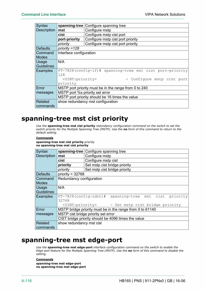
Command Line Interface VIPA Network Solutions
A-116 HB165 | PNS | 911-2PNx0 | GB | 16-06
Syntax Description
spanning-tree Configure spanning tree mst Configure mstp cist Configure mstp cist port port-priority Configure mstp cist port priority priority Configure mstp cist port priority
Defaults priority =128 Command Modes
Interface configuration
Usage Guidelines
N/A
Examples PT-7828(config-if)# spanning-tree mst cist port-priority
128
<UINT:priority> - Configure mstp cist port
priority
Error messages
MSTP port priority must be in the range from 0 to 240 MSTP port %s priority set error MSTP port priority should be 16 times the value
Related commands
show redundancy mst configuration
spanning-tree mst cist priority Use the spanning-tree mst cist priority redundancy configuration command on the switch to set the switch priority for the Multiple Spanning Tree (MSTP). Use the no form of this command to return to the default setting.
Commands
spanning-tree mst cist priority priority no spanning-tree mst cist priority
Syntax Description
spanning-tree Configure spanning tree mst Configure mstp cist Configure mstp cist priority Set mstp cist bridge priority priority Set mstp cist bridge priority
Defaults priority = 32768 Command Modes
Redundancy configuration
Usage Guidelines
N/A
Examples PT-7828(config-rdnt)# spanning-tree mst cist priority
32768
<UINT:priority> - Set mstp cist bridge priority
Error messages
MSTP bridge priority must be in the range from 0 to 61140 MSTP cist bridge priority set error CIST bridge priority should be 4096 times the value
Related commands
show redundancy mst cist
spanning-tree mst edge-port Use the spanning-tree mst edge-port interface configuration command on the switch to enable the Edge port feature for the Multiple Spanning Tree (MSTP). Use the no form of this command to disable the setting.
Commands
spanning-tree mst edge-port no spanning-tree mst edge-port
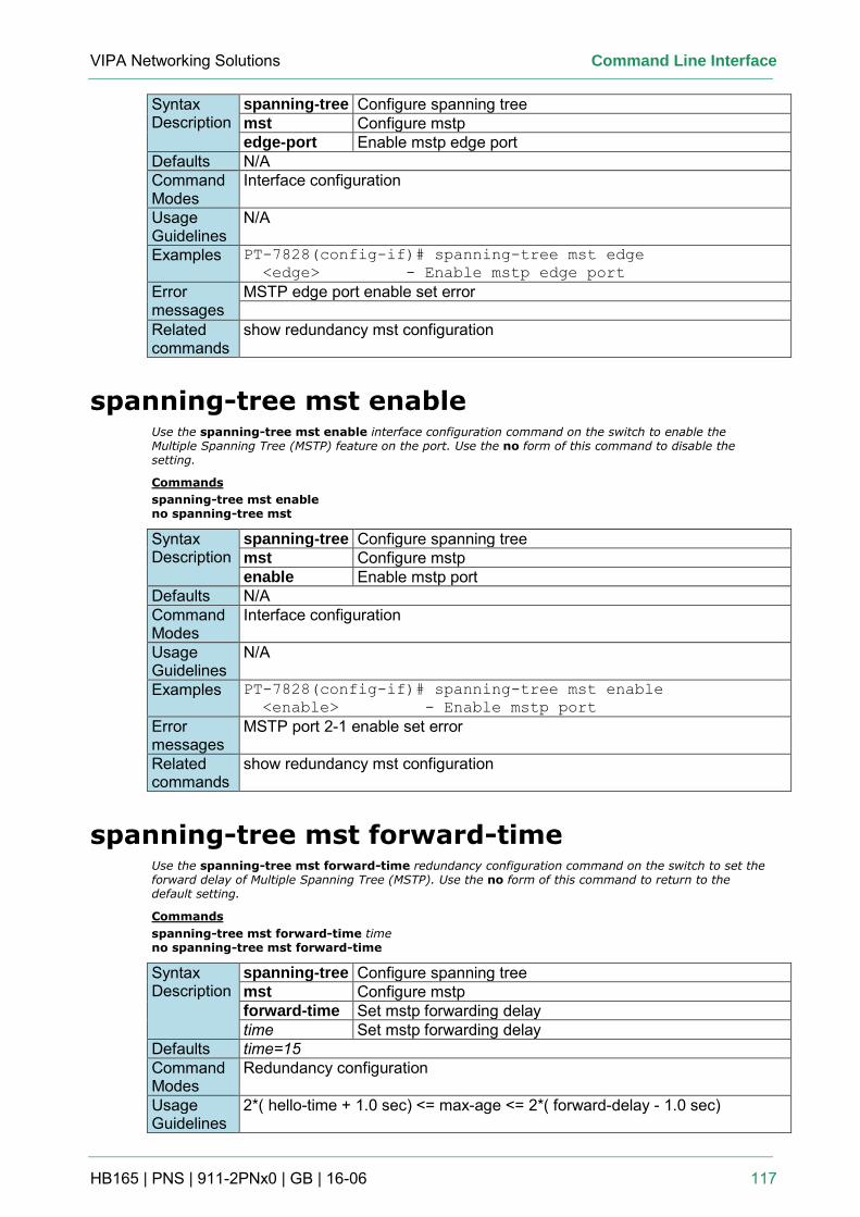
VIPA Networking Solutions Command Line Interface
HB165 | PNS | 911-2PNx0 | GB | 16-06 117
Syntax Description
spanning-tree Configure spanning tree mst Configure mstp edge-port Enable mstp edge port
Defaults N/A Command Modes
Interface configuration
Usage Guidelines
N/A
Examples PT-7828(config-if)# spanning-tree mst edge
<edge> - Enable mstp edge port
Error messages
MSTP edge port enable set error
Related commands
show redundancy mst configuration
spanning-tree mst enable Use the spanning-tree mst enable interface configuration command on the switch to enable the Multiple Spanning Tree (MSTP) feature on the port. Use the no form of this command to disable the setting.
Commands
spanning-tree mst enable no spanning-tree mst
Syntax Description
spanning-tree Configure spanning tree mst Configure mstp enable Enable mstp port
Defaults N/A Command Modes
Interface configuration
Usage Guidelines
N/A
Examples PT-7828(config-if)# spanning-tree mst enable
<enable> - Enable mstp port
Error messages
MSTP port 2-1 enable set error
Related commands
show redundancy mst configuration
spanning-tree mst forward-time Use the spanning-tree mst forward-time redundancy configuration command on the switch to set the forward delay of Multiple Spanning Tree (MSTP). Use the no form of this command to return to the default setting.
Commands
spanning-tree mst forward-time time no spanning-tree mst forward-time
Syntax Description
spanning-tree Configure spanning tree mst Configure mstp forward-time Set mstp forwarding delay time Set mstp forwarding delay
Defaults time=15 Command Modes
Redundancy configuration
Usage Guidelines
2*( hello-time + 1.0 sec) <= max-age <= 2*( forward-delay - 1.0 sec)
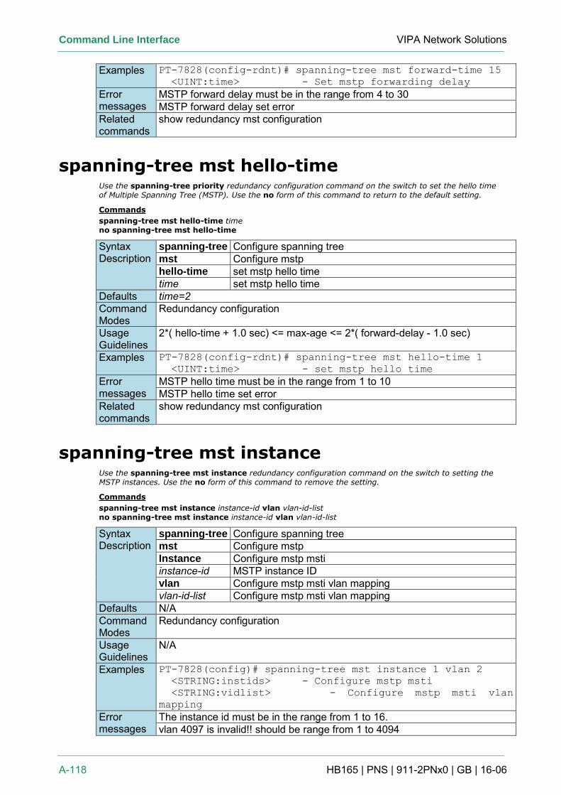
Command Line Interface VIPA Network Solutions
A-118 HB165 | PNS | 911-2PNx0 | GB | 16-06
Examples PT-7828(config-rdnt)# spanning-tree mst forward-time 15
<UINT:time> - Set mstp forwarding delay
Error messages
MSTP forward delay must be in the range from 4 to 30 MSTP forward delay set error
Related commands
show redundancy mst configuration
spanning-tree mst hello-time Use the spanning-tree priority redundancy configuration command on the switch to set the hello time of Multiple Spanning Tree (MSTP). Use the no form of this command to return to the default setting.
Commands
spanning-tree mst hello-time time no spanning-tree mst hello-time
Syntax Description
spanning-tree Configure spanning tree mst Configure mstp hello-time set mstp hello time time set mstp hello time
Defaults time=2 Command Modes
Redundancy configuration
Usage Guidelines
2*( hello-time + 1.0 sec) <= max-age <= 2*( forward-delay - 1.0 sec)
Examples PT-7828(config-rdnt)# spanning-tree mst hello-time 1
<UINT:time> - set mstp hello time
Error messages
MSTP hello time must be in the range from 1 to 10 MSTP hello time set error
Related commands
show redundancy mst configuration
spanning-tree mst instance Use the spanning-tree mst instance redundancy configuration command on the switch to setting the MSTP instances. Use the no form of this command to remove the setting.
Commands
spanning-tree mst instance instance-id vlan vlan-id-list no spanning-tree mst instance instance-id vlan vlan-id-list
Syntax Description
spanning-tree Configure spanning tree mst Configure mstp Instance Configure mstp msti instance-id MSTP instance ID vlan Configure mstp msti vlan mapping vlan-id-list Configure mstp msti vlan mapping
Defaults N/A Command Modes
Redundancy configuration
Usage Guidelines
N/A
Examples PT-7828(config)# spanning-tree mst instance 1 vlan 2
<STRING:instids> - Configure mstp msti
<STRING:vidlist> - Configure mstp msti vlan
mapping
Error messages
The instance id must be in the range from 1 to 16. vlan 4097 is invalid!! should be range from 1 to 4094
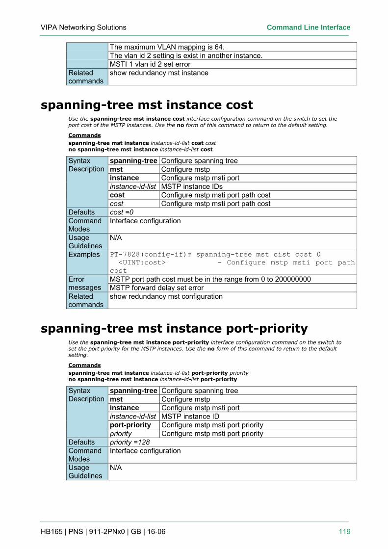
VIPA Networking Solutions Command Line Interface
HB165 | PNS | 911-2PNx0 | GB | 16-06 119
The maximum VLAN mapping is 64. The vlan id 2 setting is exist in another instance. MSTI 1 vlan id 2 set error
Related commands
show redundancy mst instance
spanning-tree mst instance cost Use the spanning-tree mst instance cost interface configuration command on the switch to set the port cost of the MSTP instances. Use the no form of this command to return to the default setting.
Commands
spanning-tree mst instance instance-id-list cost cost no spanning-tree mst instance instance-id-list cost
Syntax Description
spanning-tree Configure spanning tree mst Configure mstp instance Configure mstp msti port instance-id-list MSTP instance IDs cost Configure mstp msti port path cost cost Configure mstp msti port path cost
Defaults cost =0 Command Modes
Interface configuration
Usage Guidelines
N/A
Examples PT-7828(config-if)# spanning-tree mst cist cost 0
<UINT:cost> - Configure mstp msti port path
cost
Error messages
MSTP port path cost must be in the range from 0 to 200000000 MSTP forward delay set error
Related commands
show redundancy mst configuration
spanning-tree mst instance port-priority Use the spanning-tree mst instance port-priority interface configuration command on the switch to set the port priority for the MSTP instances. Use the no form of this command to return to the default setting.
Commands
spanning-tree mst instance instance-id-list port-priority priority no spanning-tree mst instance instance-id-list port-priority
Syntax Description
spanning-tree Configure spanning tree mst Configure mstp instance Configure mstp msti port instance-id-list MSTP instance ID port-priority Configure mstp msti port priority priority Configure mstp msti port priority
Defaults priority =128 Command Modes
Interface configuration
Usage Guidelines
N/A
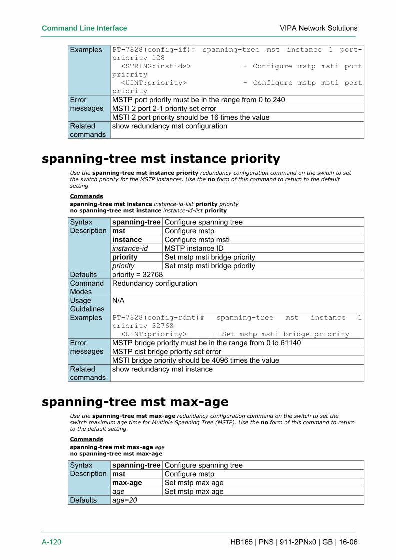
Command Line Interface VIPA Network Solutions
A-120 HB165 | PNS | 911-2PNx0 | GB | 16-06
Examples PT-7828(config-if)# spanning-tree mst instance 1 port-
priority 128
<STRING:instids> - Configure mstp msti port
priority
<UINT:priority> - Configure mstp msti port
priority
Error messages
MSTP port priority must be in the range from 0 to 240 MSTI 2 port 2-1 priority set error MSTI 2 port priority should be 16 times the value
Related commands
show redundancy mst configuration
spanning-tree mst instance priority Use the spanning-tree mst instance priority redundancy configuration command on the switch to set the switch priority for the MSTP instances. Use the no form of this command to return to the default setting.
Commands
spanning-tree mst instance instance-id-list priority priority no spanning-tree mst instance instance-id-list priority
Syntax Description
spanning-tree Configure spanning tree mst Configure mstp instance Configure mstp msti instance-id MSTP instance ID priority Set mstp msti bridge priority priority Set mstp msti bridge priority
Defaults priority = 32768 Command Modes
Redundancy configuration
Usage Guidelines
N/A
Examples PT-7828(config-rdnt)# spanning-tree mst instance 1
priority 32768
<UINT:priority> - Set mstp msti bridge priority
Error messages
MSTP bridge priority must be in the range from 0 to 61140 MSTP cist bridge priority set error MSTI bridge priority should be 4096 times the value
Related commands
show redundancy mst instance
spanning-tree mst max-age Use the spanning-tree mst max-age redundancy configuration command on the switch to set the switch maximum age time for Multiple Spanning Tree (MSTP). Use the no form of this command to return to the default setting.
Commands
spanning-tree mst max-age age no spanning-tree mst max-age
Syntax Description
spanning-tree Configure spanning tree mst Configure mstp max-age Set mstp max age age Set mstp max age
Defaults age=20
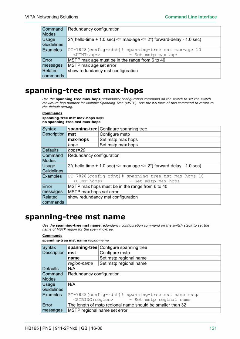
VIPA Networking Solutions Command Line Interface
HB165 | PNS | 911-2PNx0 | GB | 16-06 121
Command Modes
Redundancy configuration
Usage Guidelines
2*( hello-time + 1.0 sec) <= max-age <= 2*( forward-delay - 1.0 sec)
Examples PT-7828(config-rdnt)# spanning-tree mst max-age 10
<UINT:age> - Set mstp max age
Error messages
MSTP max age must be in the range from 6 to 40 MSTP max age set error
Related commands
show redundancy mst configuration
spanning-tree mst max-hops Use the spanning-tree max-hops redundancy configuration command on the switch to set the switch maximum hop number for Multiple Spanning Tree (MSTP). Use the no form of this command to return to the default setting.
Commands
spanning-tree mst max-hops hops no spanning-tree mst max-hops
Syntax Description
spanning-tree Configure spanning tree mst Configure mstp max-hops Set mstp max hops hops Set mstp max hops
Defaults hops=20 Command Modes
Redundancy configuration
Usage Guidelines
2*( hello-time + 1.0 sec) <= max-age <= 2*( forward-delay - 1.0 sec)
Examples PT-7828(config-rdnt)# spanning-tree mst max-hops 10
<UINT:hops> - Set mstp max hops
Error messages
MSTP max hops must be in the range from 6 to 40 MSTP max hops set error
Related commands
show redundancy mst configuration
spanning-tree mst name Use the spanning-tree mst name redundancy configuration command on the switch stack to set the name of MSTP region for the spanning-tree.
Commands
spanning-tree mst name region-name
Syntax Description
spanning-tree Configure spanning tree mst Configure mstp name Set mstp regional name region-name Set mstp regional name
Defaults N/A Command Modes
Redundancy configuration
Usage Guidelines
N/A
Examples PT-7828(config-rdnt)# spanning-tree mst name mstp
<STRING:region> - Set mstp reginal name
Error messages
The length of mstp regional name should be smaller than 32 MSTP regional name set error
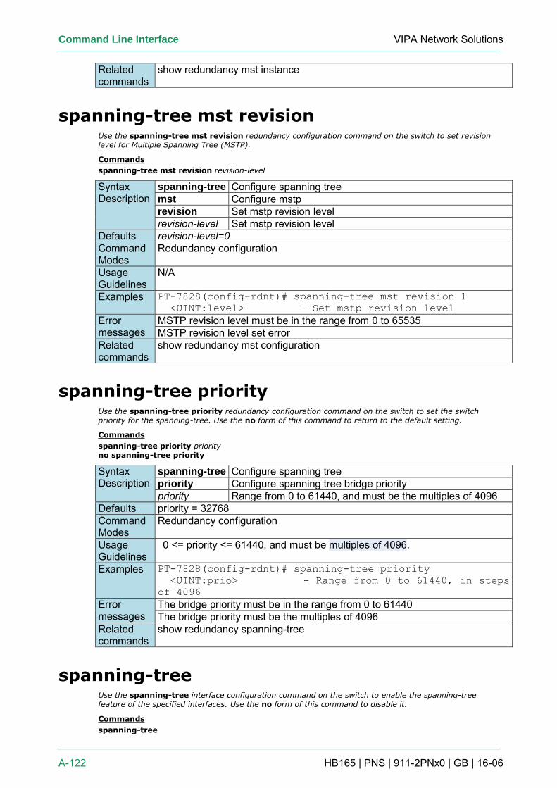
Command Line Interface VIPA Network Solutions
A-122 HB165 | PNS | 911-2PNx0 | GB | 16-06
Related commands
show redundancy mst instance
spanning-tree mst revision Use the spanning-tree mst revision redundancy configuration command on the switch to set revision level for Multiple Spanning Tree (MSTP).
Commands
spanning-tree mst revision revision-level
Syntax Description
spanning-tree Configure spanning tree mst Configure mstp revision Set mstp revision level revision-level Set mstp revision level
Defaults revision-level=0 Command Modes
Redundancy configuration
Usage Guidelines
N/A
Examples PT-7828(config-rdnt)# spanning-tree mst revision 1
<UINT:level> - Set mstp revision level
Error messages
MSTP revision level must be in the range from 0 to 65535 MSTP revision level set error
Related commands
show redundancy mst configuration
spanning-tree priority Use the spanning-tree priority redundancy configuration command on the switch to set the switch priority for the spanning-tree. Use the no form of this command to return to the default setting.
Commands
spanning-tree priority priority no spanning-tree priority
Syntax Description
spanning-tree Configure spanning tree priority Configure spanning tree bridge priority priority Range from 0 to 61440, and must be the multiples of 4096
Defaults priority = 32768 Command Modes
Redundancy configuration
Usage Guidelines
0 <= priority <= 61440, and must be multiples of 4096.
Examples PT-7828(config-rdnt)# spanning-tree priority
<UINT:prio> - Range from 0 to 61440, in steps
of 4096
Error messages
The bridge priority must be in the range from 0 to 61440 The bridge priority must be the multiples of 4096
Related commands
show redundancy spanning-tree
spanning-tree Use the spanning-tree interface configuration command on the switch to enable the spanning-tree feature of the specified interfaces. Use the no form of this command to disable it.
Commands
spanning-tree
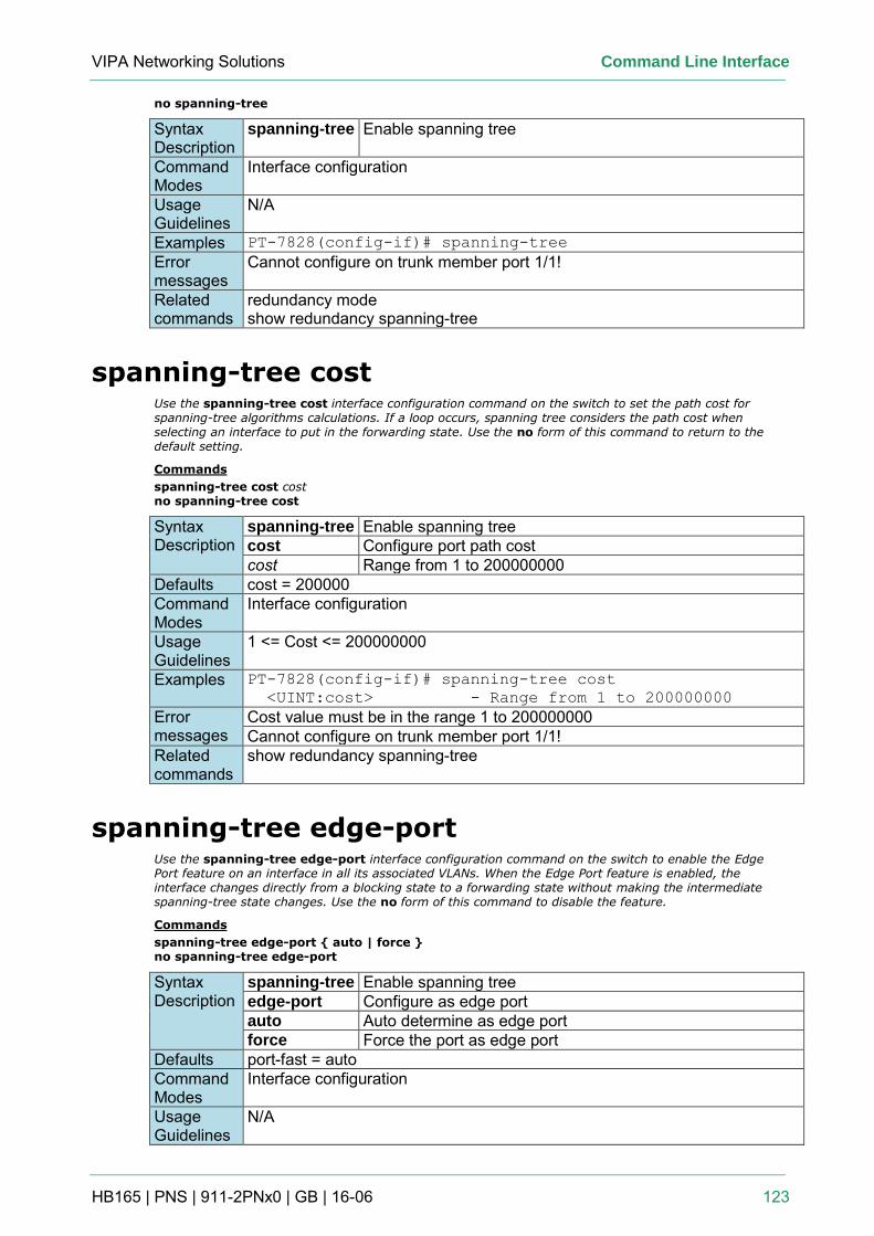
VIPA Networking Solutions Command Line Interface
HB165 | PNS | 911-2PNx0 | GB | 16-06 123
no spanning-tree
Syntax Description
spanning-tree Enable spanning tree
Command Modes
Interface configuration
Usage Guidelines
N/A
Examples PT-7828(config-if)# spanning-tree
Error messages
Cannot configure on trunk member port 1/1!
Related commands
redundancy mode show redundancy spanning-tree
spanning-tree cost Use the spanning-tree cost interface configuration command on the switch to set the path cost for spanning-tree algorithms calculations. If a loop occurs, spanning tree considers the path cost when selecting an interface to put in the forwarding state. Use the no form of this command to return to the default setting.
Commands
spanning-tree cost cost no spanning-tree cost
Syntax Description
spanning-tree Enable spanning tree cost Configure port path cost cost Range from 1 to 200000000
Defaults cost = 200000 Command Modes
Interface configuration
Usage Guidelines
1 <= Cost <= 200000000
Examples PT-7828(config-if)# spanning-tree cost
<UINT:cost> - Range from 1 to 200000000
Error messages
Cost value must be in the range 1 to 200000000 Cannot configure on trunk member port 1/1!
Related commands
show redundancy spanning-tree
spanning-tree edge-port Use the spanning-tree edge-port interface configuration command on the switch to enable the Edge Port feature on an interface in all its associated VLANs. When the Edge Port feature is enabled, the interface changes directly from a blocking state to a forwarding state without making the intermediate spanning-tree state changes. Use the no form of this command to disable the feature.
Commands
spanning-tree edge-port { auto | force } no spanning-tree edge-port
Syntax Description
spanning-tree Enable spanning tree edge-port Configure as edge port auto Auto determine as edge port force Force the port as edge port
Defaults port-fast = auto Command Modes
Interface configuration
Usage Guidelines
N/A
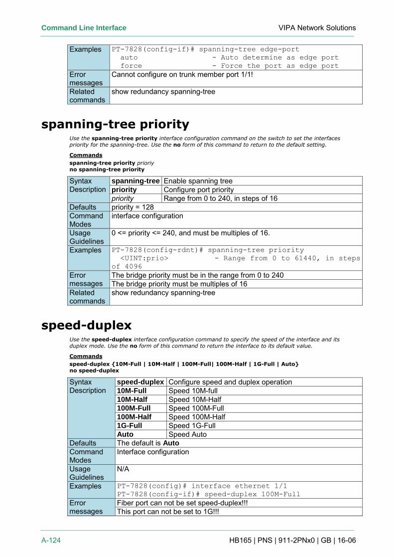
Command Line Interface VIPA Network Solutions
A-124 HB165 | PNS | 911-2PNx0 | GB | 16-06
Examples PT-7828(config-if)# spanning-tree edge-port
auto - Auto determine as edge port
force - Force the port as edge port
Error messages
Cannot configure on trunk member port 1/1!
Related commands
show redundancy spanning-tree
spanning-tree priority Use the spanning-tree priority interface configuration command on the switch to set the interfaces priority for the spanning-tree. Use the no form of this command to return to the default setting.
Commands
spanning-tree priority prioriy no spanning-tree priority
Syntax Description
spanning-tree Enable spanning tree priority Configure port priority priority Range from 0 to 240, in steps of 16
Defaults priority = 128 Command Modes
interface configuration
Usage Guidelines
0 <= priority <= 240, and must be multiples of 16.
Examples PT-7828(config-rdnt)# spanning-tree priority
<UINT:prio> - Range from 0 to 61440, in steps
of 4096
Error messages
The bridge priority must be in the range from 0 to 240 The bridge priority must be multiples of 16
Related commands
show redundancy spanning-tree
speed-duplex Use the speed-duplex interface configuration command to specify the speed of the interface and its duplex mode. Use the no form of this command to return the interface to its default value.
Commands
speed-duplex {10M-Full | 10M-Half | 100M-Full| 100M-Half | 1G-Full | Auto} no speed-duplex
Syntax Description
speed-duplex Configure speed and duplex operation 10M-Full Speed 10M-full 10M-Half Speed 10M-Half 100M-Full Speed 100M-Full 100M-Half Speed 100M-Half 1G-Full Speed 1G-Full Auto Speed Auto
Defaults The default is Auto Command Modes
Interface configuration
Usage Guidelines
N/A
Examples PT-7828(config)# interface ethernet 1/1
PT-7828(config-if)# speed-duplex 100M-Full
Error messages
Fiber port can not be set speed-duplex!!! This port can not be set to 1G!!!
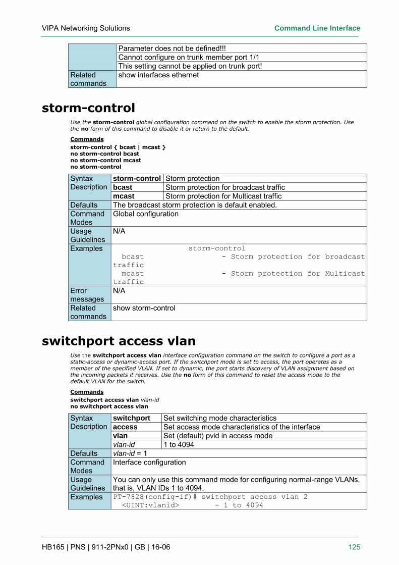
VIPA Networking Solutions Command Line Interface
HB165 | PNS | 911-2PNx0 | GB | 16-06 125
Parameter does not be defined!!! Cannot configure on trunk member port 1/1 This setting cannot be applied on trunk port!
Related commands
show interfaces ethernet
storm-control Use the storm-control global configuration command on the switch to enable the storm protection. Use the no form of this command to disable it or return to the default.
Commands
storm-control { bcast | mcast } no storm-control bcast no storm-control mcast no storm-control
Syntax Description
storm-control Storm protection bcast Storm protection for broadcast traffic mcast Storm protection for Multicast traffic
Defaults The broadcast storm protection is default enabled. Command Modes
Global configuration
Usage Guidelines
N/A
Examples storm-control
bcast - Storm protection for broadcast
traffic
mcast - Storm protection for Multicast
traffic
Error messages
N/A
Related commands
show storm-control
switchport access vlan Use the switchport access vlan interface configuration command on the switch to configure a port as a static-access or dynamic-access port. If the switchport mode is set to access, the port operates as a member of the specified VLAN. If set to dynamic, the port starts discovery of VLAN assignment based on the incoming packets it receives. Use the no form of this command to reset the access mode to the default VLAN for the switch.
Commands
switchport access vlan vlan-id no switchport access vlan
Syntax Description
switchport Set switching mode characteristics access Set access mode characteristics of the interface vlan Set (default) pvid in access mode vlan-id 1 to 4094
Defaults vlan-id = 1 Command Modes
Interface configuration
Usage Guidelines
You can only use this command mode for configuring normal-range VLANs, that is, VLAN IDs 1 to 4094.
Examples PT-7828(config-if)# switchport access vlan 2
<UINT:vlanid> - 1 to 4094
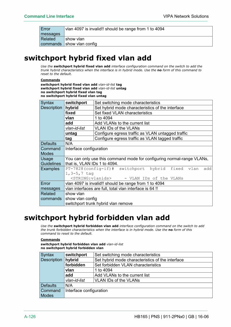
Command Line Interface VIPA Network Solutions
A-126 HB165 | PNS | 911-2PNx0 | GB | 16-06
Error messages
vlan 4097 is invalid!! should be range from 1 to 4094
Related commands
show vlan show vlan config
switchport hybrid fixed vlan add Use the switchport hybrid fixed vlan add interface configuration command on the switch to add the
trunk hybrid characteristics when the interface is in hybrid mode. Use the no form of this command to reset to the default.
Commands
switchport hybrid fixed vlan add vlan-id-list tag switchport hybrid fixed vlan add vlan-id-list untag no switchport hybrid fixed vlan tag no switchport hybrid fixed vlan untag
Syntax Description
switchport Set switching mode characteristics hybrid Set hybrid mode characteristics of the interface fixed Set fixed VLAN characteristics vlan 1 to 4094 add Add VLANs to the current list vlan-id-list VLAN IDs of the VLANs untag Configure egress traffic as VLAN untagged traffic tag Configure egress traffic as VLAN tagged traffic
Defaults N/A Command Modes
Interface configuration
Usage Guidelines
You can only use this command mode for configuring normal-range VLANs, that is, VLAN IDs 1 to 4094.
Examples PT-7828(config-if)# switchport hybrid fixed vlan add
1,3-5,7 tag
<STRING:vlanids> - VLAN IDs of the VLANs
Error messages
vlan 4097 is invalid!! should be range from 1 to 4094 vlan interfaces are full, total vlan interface is 64 !!
Related commands
show vlan show vlan config switchport trunk hybrid vlan remove
switchport hybrid forbidden vlan add Use the switchport hybrid forbidden vlan add interface configuration command on the switch to add the trunk forbidden characteristics when the interface is in hybrid mode. Use the no form of this command to reset to the default.
Commands
switchport hybrid forbidden vlan add vlan-id-list no switchport hybrid forbidden vlan
Syntax Description
switchport Set switching mode characteristics hybrid Set hybrid mode characteristics of the interface forbidden Set forbidden VLAN characteristics vlan 1 to 4094 add Add VLANs to the current list vlan-id-list VLAN IDs of the VLANs
Defaults N/A Command Modes
Interface configuration
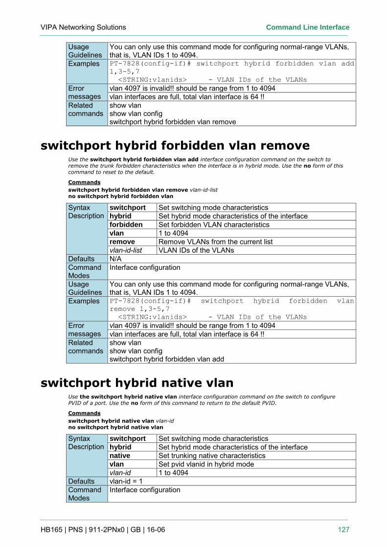
VIPA Networking Solutions Command Line Interface
HB165 | PNS | 911-2PNx0 | GB | 16-06 127
Usage Guidelines
You can only use this command mode for configuring normal-range VLANs, that is, VLAN IDs 1 to 4094.
Examples PT-7828(config-if)# switchport hybrid forbidden vlan add
1,3-5,7
<STRING:vlanids> - VLAN IDs of the VLANs
Error messages
vlan 4097 is invalid!! should be range from 1 to 4094 vlan interfaces are full, total vlan interface is 64 !!
Related commands
show vlan show vlan config switchport hybrid forbidden vlan remove
switchport hybrid forbidden vlan remove Use the switchport hybrid forbidden vlan add interface configuration command on the switch to remove the trunk forbidden characteristics when the interface is in hybrid mode. Use the no form of this command to reset to the default.
Commands
switchport hybrid forbidden vlan remove vlan-id-list no switchport hybrid forbidden vlan
Syntax Description
switchport Set switching mode characteristics hybrid Set hybrid mode characteristics of the interface forbidden Set forbidden VLAN characteristics vlan 1 to 4094 remove Remove VLANs from the current list vlan-id-list VLAN IDs of the VLANs
Defaults N/A Command Modes
Interface configuration
Usage Guidelines
You can only use this command mode for configuring normal-range VLANs, that is, VLAN IDs 1 to 4094.
Examples PT-7828(config-if)# switchport hybrid forbidden vlan
remove 1,3-5,7
<STRING:vlanids> - VLAN IDs of the VLANs
Error messages
vlan 4097 is invalid!! should be range from 1 to 4094 vlan interfaces are full, total vlan interface is 64 !!
Related commands
show vlan show vlan config switchport hybrid forbidden vlan add
switchport hybrid native vlan Use the switchport hybrid native vlan interface configuration command on the switch to configure PVID of a port. Use the no form of this command to return to the default PVID.
Commands
switchport hybrid native vlan vlan-id no switchport hybrid native vlan
Syntax Description
switchport Set switching mode characteristics hybrid Set hybrid mode characteristics of the interface native Set trunking native characteristics vlan Set pvid vlanid in hybrid mode vlan-id 1 to 4094
Defaults vlan-id = 1 Command Modes
Interface configuration
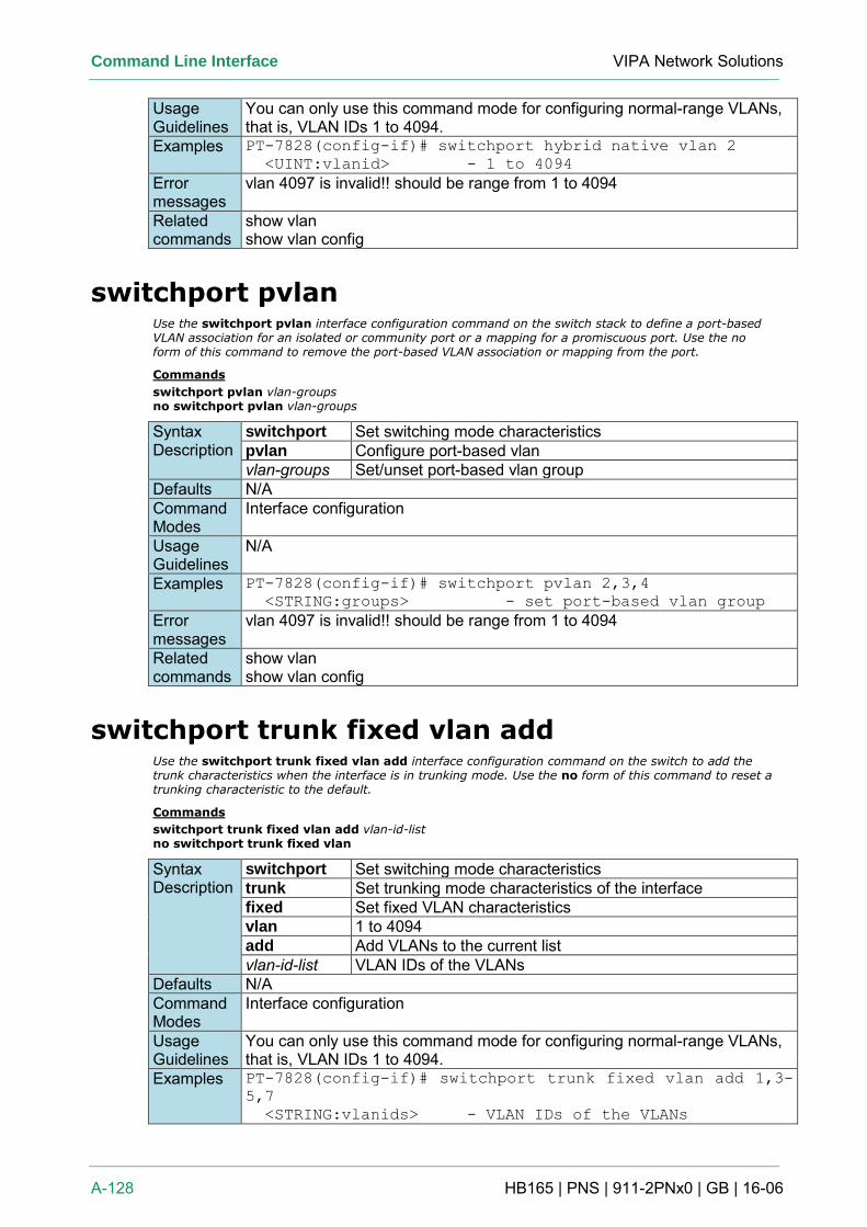
Command Line Interface VIPA Network Solutions
A-128 HB165 | PNS | 911-2PNx0 | GB | 16-06
Usage Guidelines
You can only use this command mode for configuring normal-range VLANs, that is, VLAN IDs 1 to 4094.
Examples PT-7828(config-if)# switchport hybrid native vlan 2
<UINT:vlanid> - 1 to 4094
Error messages
vlan 4097 is invalid!! should be range from 1 to 4094
Related commands
show vlan show vlan config
switchport pvlan Use the switchport pvlan interface configuration command on the switch stack to define a port-based VLAN association for an isolated or community port or a mapping for a promiscuous port. Use the no form of this command to remove the port-based VLAN association or mapping from the port.
Commands
switchport pvlan vlan-groups no switchport pvlan vlan-groups
Syntax Description
switchport Set switching mode characteristics pvlan Configure port-based vlan vlan-groups Set/unset port-based vlan group
Defaults N/A Command Modes
Interface configuration
Usage Guidelines
N/A
Examples PT-7828(config-if)# switchport pvlan 2,3,4
<STRING:groups> - set port-based vlan group
Error messages
vlan 4097 is invalid!! should be range from 1 to 4094
Related commands
show vlan show vlan config
switchport trunk fixed vlan add Use the switchport trunk fixed vlan add interface configuration command on the switch to add the trunk characteristics when the interface is in trunking mode. Use the no form of this command to reset a trunking characteristic to the default.
Commands
switchport trunk fixed vlan add vlan-id-list no switchport trunk fixed vlan
Syntax Description
switchport Set switching mode characteristics trunk Set trunking mode characteristics of the interface fixed Set fixed VLAN characteristics vlan 1 to 4094 add Add VLANs to the current list vlan-id-list VLAN IDs of the VLANs
Defaults N/A Command Modes
Interface configuration
Usage Guidelines
You can only use this command mode for configuring normal-range VLANs, that is, VLAN IDs 1 to 4094.
Examples PT-7828(config-if)# switchport trunk fixed vlan add 1,3-
5,7
<STRING:vlanids> - VLAN IDs of the VLANs
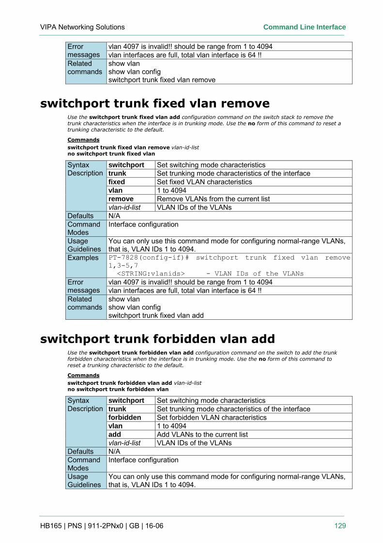
VIPA Networking Solutions Command Line Interface
HB165 | PNS | 911-2PNx0 | GB | 16-06 129
Error messages
vlan 4097 is invalid!! should be range from 1 to 4094 vlan interfaces are full, total vlan interface is 64 !!
Related commands
show vlan show vlan config switchport trunk fixed vlan remove
switchport trunk fixed vlan remove Use the switchport trunk fixed vlan add configuration command on the switch stack to remove the trunk characteristics when the interface is in trunking mode. Use the no form of this command to reset a trunking characteristic to the default.
Commands
switchport trunk fixed vlan remove vlan-id-list no switchport trunk fixed vlan
Syntax Description
switchport Set switching mode characteristics trunk Set trunking mode characteristics of the interface fixed Set fixed VLAN characteristics vlan 1 to 4094 remove Remove VLANs from the current list vlan-id-list VLAN IDs of the VLANs
Defaults N/A Command Modes
Interface configuration
Usage Guidelines
You can only use this command mode for configuring normal-range VLANs, that is, VLAN IDs 1 to 4094.
Examples PT-7828(config-if)# switchport trunk fixed vlan remove
1,3-5,7
<STRING:vlanids> - VLAN IDs of the VLANs
Error messages
vlan 4097 is invalid!! should be range from 1 to 4094 vlan interfaces are full, total vlan interface is 64 !!
Related commands
show vlan show vlan config switchport trunk fixed vlan add
switchport trunk forbidden vlan add Use the switchport trunk forbidden vlan add configuration command on the switch to add the trunk forbidden characteristics when the interface is in trunking mode. Use the no form of this command to reset a trunking characteristic to the default.
Commands
switchport trunk forbidden vlan add vlan-id-list no switchport trunk forbidden vlan
Syntax Description
switchport Set switching mode characteristics trunk Set trunking mode characteristics of the interface forbidden Set forbidden VLAN characteristics vlan 1 to 4094 add Add VLANs to the current list vlan-id-list VLAN IDs of the VLANs
Defaults N/A Command Modes
Interface configuration
Usage Guidelines
You can only use this command mode for configuring normal-range VLANs, that is, VLAN IDs 1 to 4094.
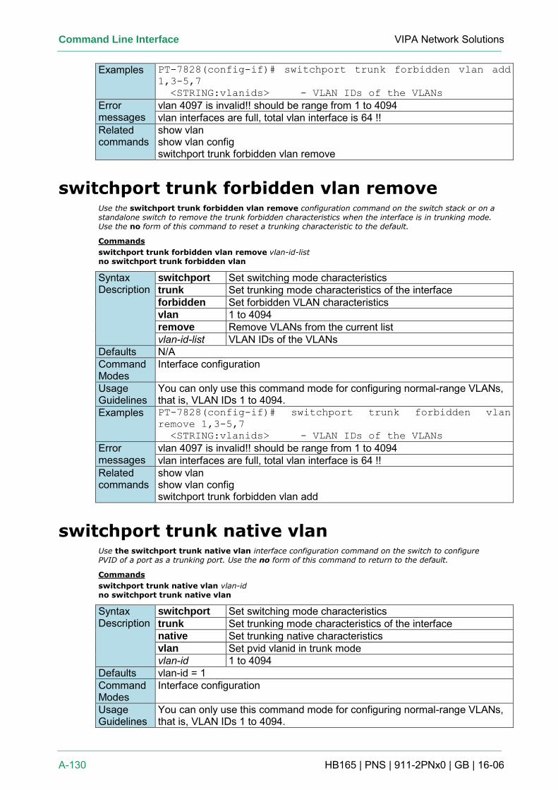
Command Line Interface VIPA Network Solutions
A-130 HB165 | PNS | 911-2PNx0 | GB | 16-06
Examples PT-7828(config-if)# switchport trunk forbidden vlan add
1,3-5,7
<STRING:vlanids> - VLAN IDs of the VLANs
Error messages
vlan 4097 is invalid!! should be range from 1 to 4094 vlan interfaces are full, total vlan interface is 64 !!
Related commands
show vlan show vlan config switchport trunk forbidden vlan remove
switchport trunk forbidden vlan remove Use the switchport trunk forbidden vlan remove configuration command on the switch stack or on a standalone switch to remove the trunk forbidden characteristics when the interface is in trunking mode. Use the no form of this command to reset a trunking characteristic to the default.
Commands
switchport trunk forbidden vlan remove vlan-id-list no switchport trunk forbidden vlan
Syntax Description
switchport Set switching mode characteristics trunk Set trunking mode characteristics of the interface forbidden Set forbidden VLAN characteristics vlan 1 to 4094 remove Remove VLANs from the current list vlan-id-list VLAN IDs of the VLANs
Defaults N/A Command Modes
Interface configuration
Usage Guidelines
You can only use this command mode for configuring normal-range VLANs, that is, VLAN IDs 1 to 4094.
Examples PT-7828(config-if)# switchport trunk forbidden vlan
remove 1,3-5,7
<STRING:vlanids> - VLAN IDs of the VLANs
Error messages
vlan 4097 is invalid!! should be range from 1 to 4094 vlan interfaces are full, total vlan interface is 64 !!
Related commands
show vlan show vlan config switchport trunk forbidden vlan add
switchport trunk native vlan Use the switchport trunk native vlan interface configuration command on the switch to configure PVID of a port as a trunking port. Use the no form of this command to return to the default.
Commands
switchport trunk native vlan vlan-id no switchport trunk native vlan
Syntax Description
switchport Set switching mode characteristics trunk Set trunking mode characteristics of the interface native Set trunking native characteristics vlan Set pvid vlanid in trunk mode vlan-id 1 to 4094
Defaults vlan-id = 1 Command Modes
Interface configuration
Usage Guidelines
You can only use this command mode for configuring normal-range VLANs, that is, VLAN IDs 1 to 4094.
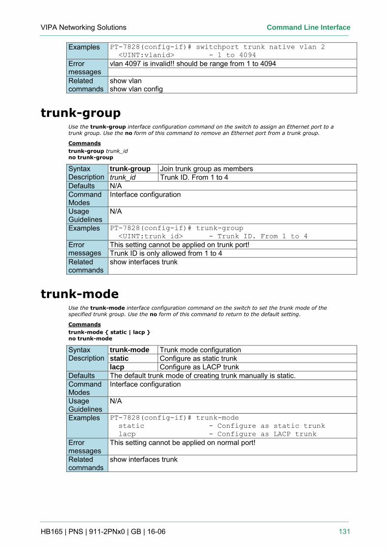
VIPA Networking Solutions Command Line Interface
HB165 | PNS | 911-2PNx0 | GB | 16-06 131
Examples PT-7828(config-if)# switchport trunk native vlan 2
<UINT:vlanid> - 1 to 4094
Error messages
vlan 4097 is invalid!! should be range from 1 to 4094
Related commands
show vlan show vlan config
trunk-group Use the trunk-group interface configuration command on the switch to assign an Ethernet port to a trunk group. Use the no form of this command to remove an Ethernet port from a trunk group.
Commands
trunk-group trunk_id no trunk-group
Syntax Description
trunk-group Join trunk group as members trunk_id Trunk ID. From 1 to 4
Defaults N/A Command Modes
Interface configuration
Usage Guidelines
N/A
Examples PT-7828(config-if)# trunk-group
<UINT:trunk_id> - Trunk ID. From 1 to 4
Error messages
This setting cannot be applied on trunk port! Trunk ID is only allowed from 1 to 4
Related commands
show interfaces trunk
trunk-mode Use the trunk-mode interface configuration command on the switch to set the trunk mode of the specified trunk group. Use the no form of this command to return to the default setting.
Commands
trunk-mode { static | lacp } no trunk-mode
Syntax Description
trunk-mode Trunk mode configuration static Configure as static trunk lacp Configure as LACP trunk
Defaults The default trunk mode of creating trunk manually is static. Command Modes
Interface configuration
Usage Guidelines
N/A
Examples PT-7828(config-if)# trunk-mode
static - Configure as static trunk
lacp - Configure as LACP trunk
Error messages
This setting cannot be applied on normal port!
Related commands
show interfaces trunk
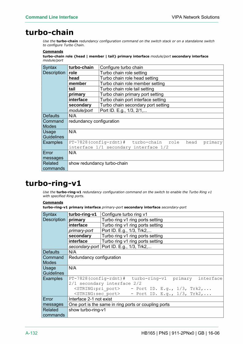
Command Line Interface VIPA Network Solutions
A-132 HB165 | PNS | 911-2PNx0 | GB | 16-06
turbo-chain Use the turbo-chain redundancy configuration command on the switch stack or on a standalone switch to configure Turbo Chain.
Commands
turbo-chain role {head | member | tail} primary interface module/port secondary interface module/port
Syntax Description
turbo-chain Configure turbo chain role Turbo chain role setting head Turbo chain role head setting member Turbo chain role member setting tail Turbo chain role tail setting primary Turbo chain primary port setting interface Turbo chain port interface setting secondary Turbo chain secondary port setting module/port Port ID. E.g., 1/3, 2/1,...
Defaults N/A Command Modes
redundancy configuration
Usage Guidelines
N/A
Examples PT-7828(config-rdnt)# turbo-chain role head primary
interface 1/1 secondary interface 1/2
Error messages
N/A
Related commands
show redundancy turbo-chain
turbo-ring-v1 Use the turbo-ring-v1 redundancy configuration command on the switch to enable the Turbo Ring v1 with specified Ring ports.
Commands
turbo-ring-v1 primary interface primary-port secondary interface secondary-port
Syntax Description
turbo-ring-v1 Configure turbo ring v1 primary Turbo ring v1 ring ports setting interface Turbo ring v1 ring ports setting primary-port Port ID. E.g., 1/3, Trk2,... secondary Turbo ring v1 ring ports setting interface Turbo ring v1 ring ports setting secondary-port Port ID. E.g., 1/3, Trk2,...
Defaults N/A Command Modes
Redundancy configuration
Usage Guidelines
N/A
Examples PT-7828(config-rdnt)# turbo-ring-v1 primary interface
2/1 secondary interface 2/2
<STRING:pri_port> - Port ID. E.g., 1/3, Trk2,...
<STRING:sec_port> - Port ID. E.g., 1/3, Trk2,...
Error messages
Interface 2-1 not exist One port is the same in ring ports or coupling ports
Related commands
show turbo-ring-v1
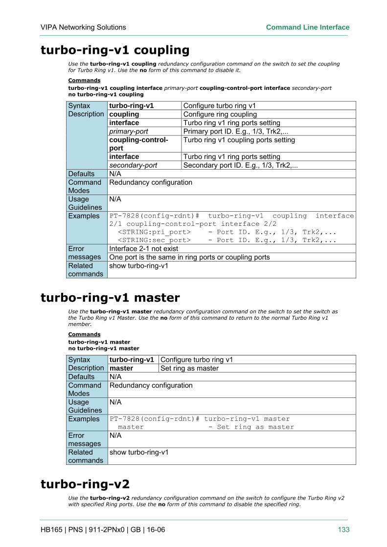
VIPA Networking Solutions Command Line Interface
HB165 | PNS | 911-2PNx0 | GB | 16-06 133
turbo-ring-v1 coupling Use the turbo-ring-v1 coupling redundancy configuration command on the switch to set the coupling for Turbo Ring v1. Use the no form of this command to disable it.
Commands
turbo-ring-v1 coupling interface primary-port coupling-control-port interface secondary-port no turbo-ring-v1 coupling
Syntax Description
turbo-ring-v1 Configure turbo ring v1 coupling Configure ring coupling interface Turbo ring v1 ring ports setting primary-port Primary port ID. E.g., 1/3, Trk2,... coupling-control-port
Turbo ring v1 coupling ports setting
interface Turbo ring v1 ring ports setting secondary-port Secondary port ID. E.g., 1/3, Trk2,...
Defaults N/A Command Modes
Redundancy configuration
Usage Guidelines
N/A
Examples PT-7828(config-rdnt)# turbo-ring-v1 coupling interface
2/1 coupling-control-port interface 2/2
<STRING:pri_port> - Port ID. E.g., 1/3, Trk2,...
<STRING:sec_port> - Port ID. E.g., 1/3, Trk2,...
Error messages
Interface 2-1 not exist One port is the same in ring ports or coupling ports
Related commands
show turbo-ring-v1
turbo-ring-v1 master Use the turbo-ring-v1 master redundancy configuration command on the switch to set the switch as the Turbo Ring v1 Master. Use the no form of this command to return to the normal Turbo Ring v1 member.
Commands
turbo-ring-v1 master no turbo-ring-v1 master
Syntax Description
turbo-ring-v1 Configure turbo ring v1 master Set ring as master
Defaults N/A Command Modes
Redundancy configuration
Usage Guidelines
N/A
Examples PT-7828(config-rdnt)# turbo-ring-v1 master
master - Set ring as master
Error messages
N/A
Related commands
show turbo-ring-v1
turbo-ring-v2 Use the turbo-ring-v2 redundancy configuration command on the switch to configure the Turbo Ring v2 with specified Ring ports. Use the no form of this command to disable the specified ring.
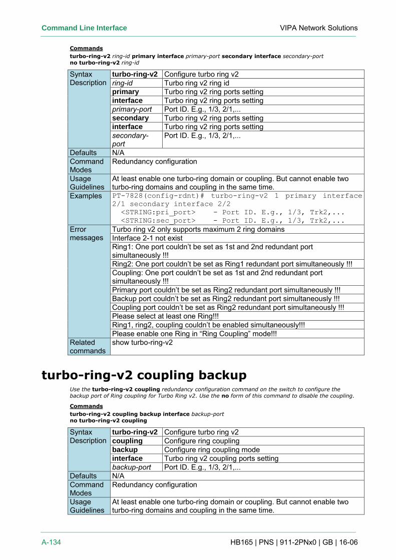
Command Line Interface VIPA Network Solutions
A-134 HB165 | PNS | 911-2PNx0 | GB | 16-06
Commands
turbo-ring-v2 ring-id primary interface primary-port secondary interface secondary-port no turbo-ring-v2 ring-id
Syntax Description
turbo-ring-v2 Configure turbo ring v2 ring-id Turbo ring v2 ring id primary Turbo ring v2 ring ports setting interface Turbo ring v2 ring ports setting primary-port Port ID. E.g., 1/3, 2/1,... secondary Turbo ring v2 ring ports setting interface Turbo ring v2 ring ports setting secondary-port
Port ID. E.g., 1/3, 2/1,...
Defaults N/A Command Modes
Redundancy configuration
Usage Guidelines
At least enable one turbo-ring domain or coupling. But cannot enable two turbo-ring domains and coupling in the same time.
Examples PT-7828(config-rdnt)# turbo-ring-v2 1 primary interface
2/1 secondary interface 2/2
<STRING:pri_port> - Port ID. E.g., 1/3, Trk2,...
<STRING:sec_port> - Port ID. E.g., 1/3, Trk2,...
Error messages
Turbo ring v2 only supports maximum 2 ring domains Interface 2-1 not exist Ring1: One port couldn’t be set as 1st and 2nd redundant port simultaneously !!! Ring2: One port couldn’t be set as Ring1 redundant port simultaneously !!! Coupling: One port couldn’t be set as 1st and 2nd redundant port simultaneously !!! Primary port couldn’t be set as Ring2 redundant port simultaneously !!! Backup port couldn’t be set as Ring2 redundant port simultaneously !!! Coupling port couldn’t be set as Ring2 redundant port simultaneously !!! Please select at least one Ring!!! Ring1, ring2, coupling couldn’t be enabled simultaneously!!! Please enable one Ring in “Ring Coupling” mode!!!
Related commands
show turbo-ring-v2
turbo-ring-v2 coupling backup Use the turbo-ring-v2 coupling redundancy configuration command on the switch to configure the backup port of Ring coupling for Turbo Ring v2. Use the no form of this command to disable the coupling.
Commands
turbo-ring-v2 coupling backup interface backup-port no turbo-ring-v2 coupling
Syntax Description
turbo-ring-v2 Configure turbo ring v2 coupling Configure ring coupling backup Configure ring coupling mode interface Turbo ring v2 coupling ports setting backup-port Port ID. E.g., 1/3, 2/1,...
Defaults N/A Command Modes
Redundancy configuration
Usage Guidelines
At least enable one turbo-ring domain or coupling. But cannot enable two turbo-ring domains and coupling in the same time.
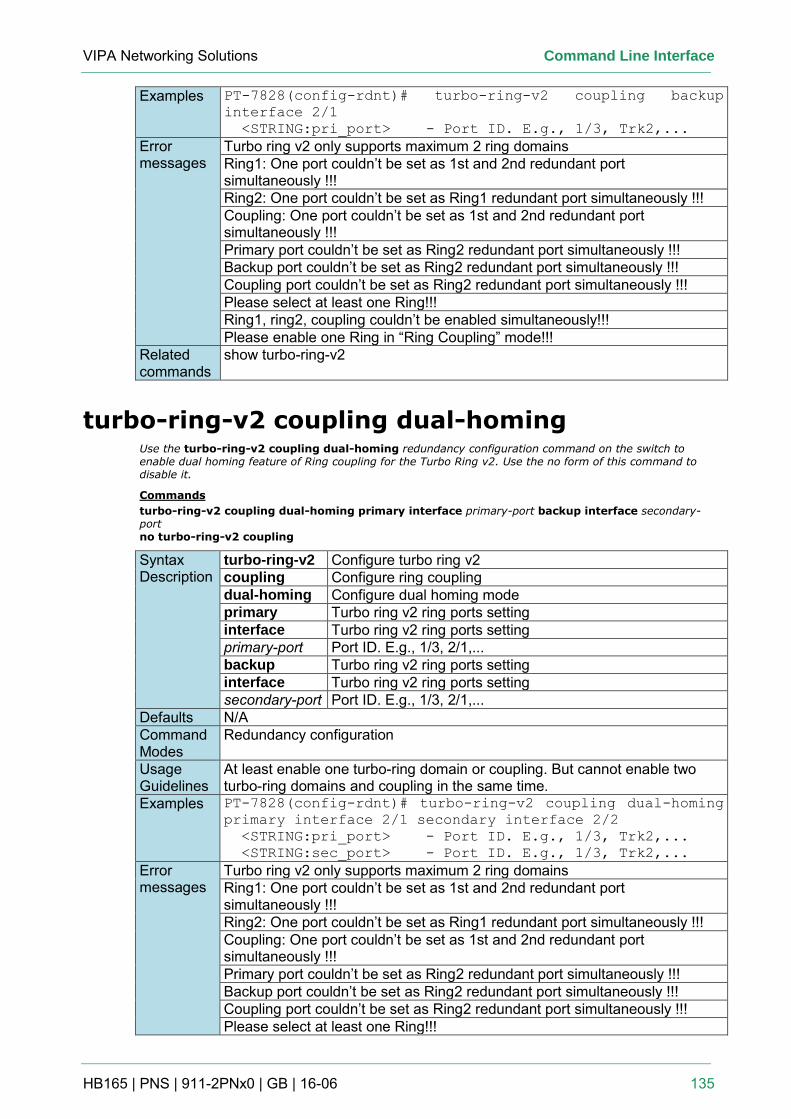
VIPA Networking Solutions Command Line Interface
HB165 | PNS | 911-2PNx0 | GB | 16-06 135
Examples PT-7828(config-rdnt)# turbo-ring-v2 coupling backup
interface 2/1
<STRING:pri_port> - Port ID. E.g., 1/3, Trk2,...
Error messages
Turbo ring v2 only supports maximum 2 ring domains Ring1: One port couldn’t be set as 1st and 2nd redundant port simultaneously !!! Ring2: One port couldn’t be set as Ring1 redundant port simultaneously !!! Coupling: One port couldn’t be set as 1st and 2nd redundant port simultaneously !!! Primary port couldn’t be set as Ring2 redundant port simultaneously !!! Backup port couldn’t be set as Ring2 redundant port simultaneously !!! Coupling port couldn’t be set as Ring2 redundant port simultaneously !!! Please select at least one Ring!!! Ring1, ring2, coupling couldn’t be enabled simultaneously!!! Please enable one Ring in “Ring Coupling” mode!!!
Related commands
show turbo-ring-v2
turbo-ring-v2 coupling dual-homing Use the turbo-ring-v2 coupling dual-homing redundancy configuration command on the switch to enable dual homing feature of Ring coupling for the Turbo Ring v2. Use the no form of this command to disable it.
Commands
turbo-ring-v2 coupling dual-homing primary interface primary-port backup interface secondary-port no turbo-ring-v2 coupling
Syntax Description
turbo-ring-v2 Configure turbo ring v2 coupling Configure ring coupling dual-homing Configure dual homing mode primary Turbo ring v2 ring ports setting interface Turbo ring v2 ring ports setting primary-port Port ID. E.g., 1/3, 2/1,... backup Turbo ring v2 ring ports setting interface Turbo ring v2 ring ports setting secondary-port Port ID. E.g., 1/3, 2/1,...
Defaults N/A Command Modes
Redundancy configuration
Usage Guidelines
At least enable one turbo-ring domain or coupling. But cannot enable two turbo-ring domains and coupling in the same time.
Examples PT-7828(config-rdnt)# turbo-ring-v2 coupling dual-homing
primary interface 2/1 secondary interface 2/2
<STRING:pri_port> - Port ID. E.g., 1/3, Trk2,...
<STRING:sec_port> - Port ID. E.g., 1/3, Trk2,...
Error messages
Turbo ring v2 only supports maximum 2 ring domains Ring1: One port couldn’t be set as 1st and 2nd redundant port simultaneously !!! Ring2: One port couldn’t be set as Ring1 redundant port simultaneously !!! Coupling: One port couldn’t be set as 1st and 2nd redundant port simultaneously !!! Primary port couldn’t be set as Ring2 redundant port simultaneously !!! Backup port couldn’t be set as Ring2 redundant port simultaneously !!! Coupling port couldn’t be set as Ring2 redundant port simultaneously !!! Please select at least one Ring!!!
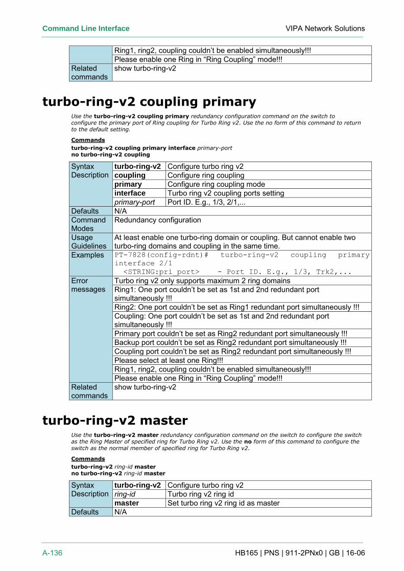
Command Line Interface VIPA Network Solutions
A-136 HB165 | PNS | 911-2PNx0 | GB | 16-06
Ring1, ring2, coupling couldn’t be enabled simultaneously!!! Please enable one Ring in “Ring Coupling” mode!!!
Related commands
show turbo-ring-v2
turbo-ring-v2 coupling primary Use the turbo-ring-v2 coupling primary redundancy configuration command on the switch to configure the primary port of Ring coupling for Turbo Ring v2. Use the no form of this command to return to the default setting.
Commands
turbo-ring-v2 coupling primary interface primary-port no turbo-ring-v2 coupling
Syntax Description
turbo-ring-v2 Configure turbo ring v2 coupling Configure ring coupling primary Configure ring coupling mode interface Turbo ring v2 coupling ports setting primary-port Port ID. E.g., 1/3, 2/1,...
Defaults N/A Command Modes
Redundancy configuration
Usage Guidelines
At least enable one turbo-ring domain or coupling. But cannot enable two turbo-ring domains and coupling in the same time.
Examples PT-7828(config-rdnt)# turbo-ring-v2 coupling primary
interface 2/1
<STRING:pri_port> - Port ID. E.g., 1/3, Trk2,...
Error messages
Turbo ring v2 only supports maximum 2 ring domains Ring1: One port couldn’t be set as 1st and 2nd redundant port simultaneously !!! Ring2: One port couldn’t be set as Ring1 redundant port simultaneously !!! Coupling: One port couldn’t be set as 1st and 2nd redundant port simultaneously !!! Primary port couldn’t be set as Ring2 redundant port simultaneously !!! Backup port couldn’t be set as Ring2 redundant port simultaneously !!! Coupling port couldn’t be set as Ring2 redundant port simultaneously !!! Please select at least one Ring!!! Ring1, ring2, coupling couldn’t be enabled simultaneously!!! Please enable one Ring in “Ring Coupling” mode!!!
Related commands
show turbo-ring-v2
turbo-ring-v2 master Use the turbo-ring-v2 master redundancy configuration command on the switch to configure the switch as the Ring Master of specified ring for Turbo Ring v2. Use the no form of this command to configure the switch as the normal member of specified ring for Turbo Ring v2.
Commands
turbo-ring-v2 ring-id master no turbo-ring-v2 ring-id master
Syntax Description
turbo-ring-v2 Configure turbo ring v2 ring-id Turbo ring v2 ring id master Set turbo ring v2 ring id as master
Defaults N/A
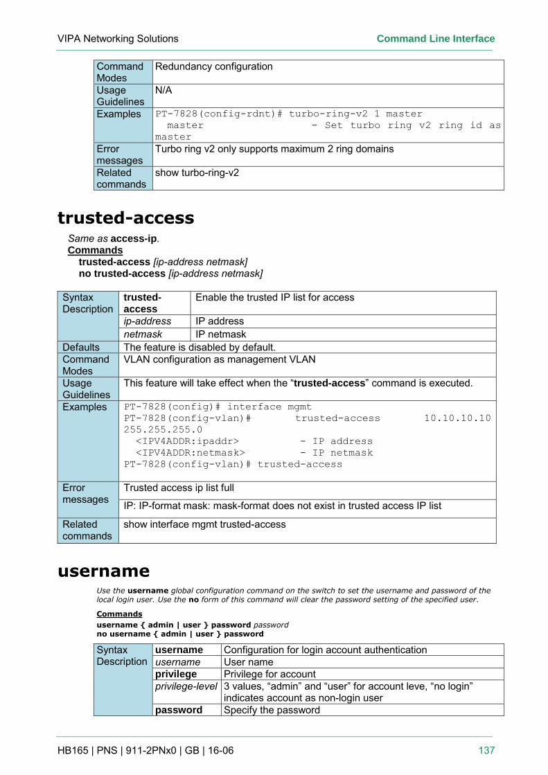
VIPA Networking Solutions Command Line Interface
HB165 | PNS | 911-2PNx0 | GB | 16-06 137
Command Modes
Redundancy configuration
Usage Guidelines
N/A
Examples PT-7828(config-rdnt)# turbo-ring-v2 1 master
master - Set turbo ring v2 ring id as
master
Error messages
Turbo ring v2 only supports maximum 2 ring domains
Related commands
show turbo-ring-v2
trusted-access Same as access-ip. Commands
trusted-access [ip-address netmask] no trusted-access [ip-address netmask]
Syntax Description
trusted-access
Enable the trusted IP list for access
ip-address IP address netmask IP netmask
Defaults The feature is disabled by default. Command Modes
VLAN configuration as management VLAN
Usage Guidelines
This feature will take effect when the “trusted-access” command is executed.
Examples PT-7828(config)# interface mgmt
PT-7828(config-vlan)# trusted-access 10.10.10.10
255.255.255.0
<IPV4ADDR:ipaddr> - IP address
<IPV4ADDR:netmask> - IP netmask
PT-7828(config-vlan)# trusted-access
Error messages
Trusted access ip list full
IP: IP-format mask: mask-format does not exist in trusted access IP list
Related commands
show interface mgmt trusted-access
username Use the username global configuration command on the switch to set the username and password of the local login user. Use the no form of this command will clear the password setting of the specified user.
Commands
username { admin | user } password password no username { admin | user } password
Syntax Description
username Configuration for login account authentication username User name privilege Privilege for account privilege-level 3 values, “admin” and “user” for account leve, “no login”
indicates account as non-login user password Specify the password
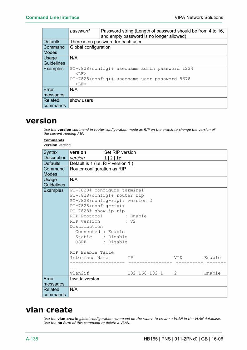
Command Line Interface VIPA Network Solutions
A-138 HB165 | PNS | 911-2PNx0 | GB | 16-06
password Password string (Length of password should be from 4 to 16, and empty password is no longer allowed)
Defaults There is no password for each user Command Modes
Global configuration
Usage Guidelines
N/A
Examples PT-7828(config)# username admin password 1234
<LF>
PT-7828(config)# username user password 5678
<LF>
Error messages
N/A
Related commands
show users
version Use the version command in router configuration mode as RIP on the switch to change the version of the current running RIP.
Commands
version version
Syntax Description
version Set RIP version version 1 | 2 | 1c
Defaults Default is 1 (i.e. RIP version 1 ) Command Modes
Router configuration as RIP
Usage Guidelines
N/A
Examples PT-7828# configure terminal
PT-7828(config)# router rip
PT-7828(config-rip)# version 2
PT-7828(config-rip)#
PT-7828# show ip rip
RIP Protocol : Enable
RIP version : V2
Distribution
Connected : Enable
Static : Disable
OSPF : Disable
RIP Enable Table
Interface Name IP VID Enable
-------------------- ---------------- ---------- -------
---
vlan2if 192.168.102.1 2 Enable
Error messages
Invalid version
Related commands
N/A
vlan create Use the vlan create global configuration command on the switch to create a VLAN in the VLAN database. Use the no form of this command to delete a VLAN.
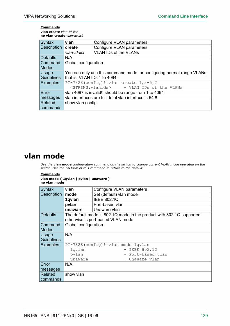
VIPA Networking Solutions Command Line Interface
HB165 | PNS | 911-2PNx0 | GB | 16-06 139
Commands
vlan create vlan-id-list no vlan create vlan-id-list
Syntax Description
vlan Configure VLAN parameters create Configure VLAN parameters vlan-id-list VLAN IDs of the VLANs
Defaults N/A Command Modes
Global configuration
Usage Guidelines
You can only use this command mode for configuring normal-range VLANs, that is, VLAN IDs 1 to 4094.
Examples PT-7828(config)# vlan create 1,3-5,7
<STRING:vlanids> - VLAN IDs of the VLANs
Error messages
vlan 4097 is invalid!! should be range from 1 to 4094 vlan interfaces are full, total vlan interface is 64 !!
Related commands
show vlan config
vlan mode Use the vlan mode configuration command on the switch to change current VLAN mode operated on the switch. Use the no form of this command to return to the default.
Commands
vlan mode { 1qvlan | pvlan | unaware } no vlan mode
Syntax Description
vlan Configure VLAN parameters mode Set (default) vlan mode 1qvlan IEEE 802.1Q pvlan Port-based vlan unaware Unaware vlan
Defaults The default mode is 802.1Q mode in the product with 802.1Q supported; otherwise is port-based VLAN mode.
Command Modes
Global configuration
Usage Guidelines
N/A
Examples PT-7828(config)# vlan mode 1qvlan
1qvlan - IEEE 802.1Q
pvlan - Port-based vlan
unaware - Unaware vlan
Error messages
N/A
Related commands
show vlan
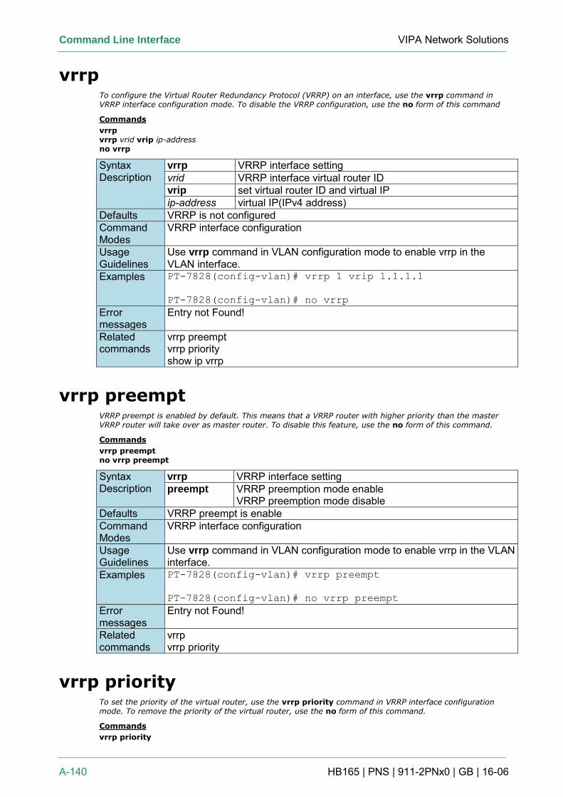
Command Line Interface VIPA Network Solutions
A-140 HB165 | PNS | 911-2PNx0 | GB | 16-06
vrrp To configure the Virtual Router Redundancy Protocol (VRRP) on an interface, use the vrrp command in VRRP interface configuration mode. To disable the VRRP configuration, use the no form of this command
Commands
vrrp vrrp vrid vrip ip-address no vrrp
Syntax Description
vrrp VRRP interface setting vrid VRRP interface virtual router ID vrip set virtual router ID and virtual IP ip-address virtual IP(IPv4 address)
Defaults VRRP is not configured Command Modes
VRRP interface configuration
Usage Guidelines
Use vrrp command in VLAN configuration mode to enable vrrp in the VLAN interface.
Examples PT-7828(config-vlan)# vrrp 1 vrip 1.1.1.1
PT-7828(config-vlan)# no vrrp
Error messages
Entry not Found!
Related commands
vrrp preempt vrrp priority show ip vrrp
vrrp preempt VRRP preempt is enabled by default. This means that a VRRP router with higher priority than the master VRRP router will take over as master router. To disable this feature, use the no form of this command.
Commands
vrrp preempt no vrrp preempt
Syntax Description
vrrp VRRP interface setting preempt VRRP preemption mode enable
VRRP preemption mode disable Defaults VRRP preempt is enable Command Modes
VRRP interface configuration
Usage Guidelines
Use vrrp command in VLAN configuration mode to enable vrrp in the VLAN interface.
Examples PT-7828(config-vlan)# vrrp preempt
PT-7828(config-vlan)# no vrrp preempt
Error messages
Entry not Found!
Related commands
vrrp vrrp priority
vrrp priority To set the priority of the virtual router, use the vrrp priority command in VRRP interface configuration mode. To remove the priority of the virtual router, use the no form of this command.
Commands
vrrp priority
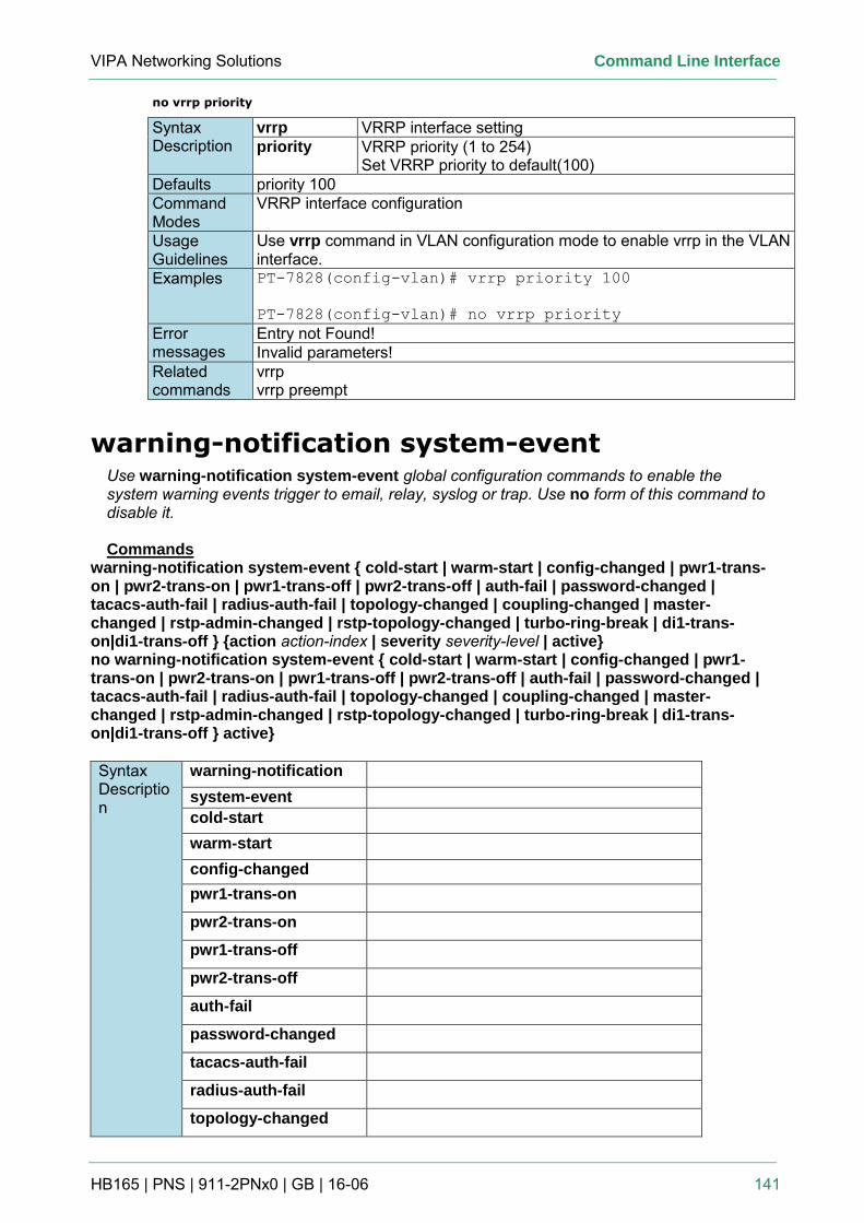
VIPA Networking Solutions Command Line Interface
HB165 | PNS | 911-2PNx0 | GB | 16-06 141
no vrrp priority
Syntax Description
vrrp VRRP interface setting priority VRRP priority (1 to 254)
Set VRRP priority to default(100) Defaults priority 100 Command Modes
VRRP interface configuration
Usage Guidelines
Use vrrp command in VLAN configuration mode to enable vrrp in the VLAN interface.
Examples PT-7828(config-vlan)# vrrp priority 100
PT-7828(config-vlan)# no vrrp priority
Error messages
Entry not Found! Invalid parameters!
Related commands
vrrp vrrp preempt
warning-notification system-event Use warning-notification system-event global configuration commands to enable the system warning events trigger to email, relay, syslog or trap. Use no form of this command to disable it. Commands
warning-notification system-event { cold-start | warm-start | config-changed | pwr1-trans-on | pwr2-trans-on | pwr1-trans-off | pwr2-trans-off | auth-fail | password-changed | tacacs-auth-fail | radius-auth-fail | topology-changed | coupling-changed | master-changed | rstp-admin-changed | rstp-topology-changed | turbo-ring-break | di1-trans-on|di1-trans-off } {action action-index | severity severity-level | active} no warning-notification system-event { cold-start | warm-start | config-changed | pwr1-trans-on | pwr2-trans-on | pwr1-trans-off | pwr2-trans-off | auth-fail | password-changed | tacacs-auth-fail | radius-auth-fail | topology-changed | coupling-changed | master-changed | rstp-admin-changed | rstp-topology-changed | turbo-ring-break | di1-trans-on|di1-trans-off } active}
Syntax Description
warning-notification system-event cold-start warm-start config-changed pwr1-trans-on
pwr2-trans-on
pwr1-trans-off
pwr2-trans-off
auth-fail
password-changed
tacacs-auth-fail
radius-auth-fail
topology-changed
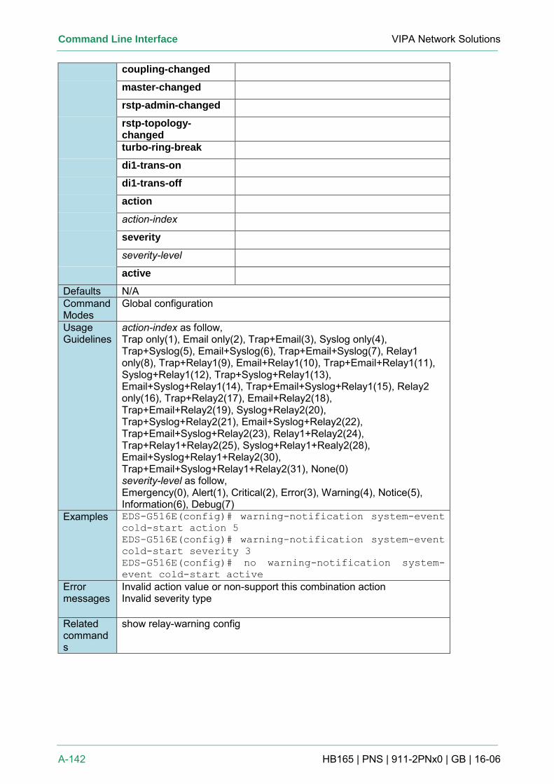
Command Line Interface VIPA Network Solutions
A-142 HB165 | PNS | 911-2PNx0 | GB | 16-06
coupling-changed
master-changed
rstp-admin-changed
rstp-topology-changed
turbo-ring-break
di1-trans-on
di1-trans-off
action
action-index
severity
severity-level
active
Defaults N/A Command Modes
Global configuration
Usage Guidelines
action-index as follow, Trap only(1), Email only(2), Trap+Email(3), Syslog only(4), Trap+Syslog(5), Email+Syslog(6), Trap+Email+Syslog(7), Relay1 only(8), Trap+Relay1(9), Email+Relay1(10), Trap+Email+Relay1(11), Syslog+Relay1(12), Trap+Syslog+Relay1(13), Email+Syslog+Relay1(14), Trap+Email+Syslog+Relay1(15), Relay2 only(16), Trap+Relay2(17), Email+Relay2(18), Trap+Email+Relay2(19), Syslog+Relay2(20), Trap+Syslog+Relay2(21), Email+Syslog+Relay2(22), Trap+Email+Syslog+Relay2(23), Relay1+Relay2(24), Trap+Relay1+Relay2(25), Syslog+Relay1+Realy2(28), Email+Syslog+Relay1+Relay2(30), Trap+Email+Syslog+Relay1+Relay2(31), None(0) severity-level as follow, Emergency(0), Alert(1), Critical(2), Error(3), Warning(4), Notice(5), Information(6), Debug(7)
Examples EDS-G516E(config)# warning-notification system-event
cold-start action 5
EDS-G516E(config)# warning-notification system-event
cold-start severity 3
EDS-G516E(config)# no warning-notification system-
event cold-start active
Error messages
Invalid action value or non-support this combination action Invalid severity type
Related commands
show relay-warning config
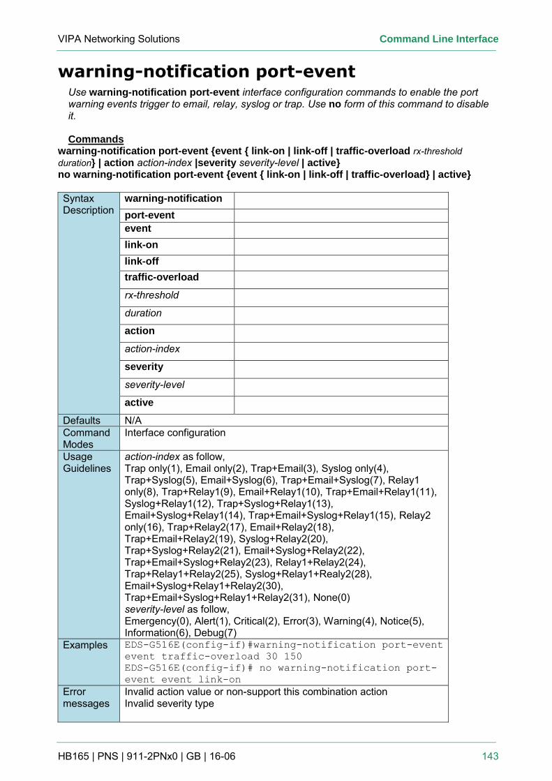
VIPA Networking Solutions Command Line Interface
HB165 | PNS | 911-2PNx0 | GB | 16-06 143
warning-notification port-event Use warning-notification port-event interface configuration commands to enable the port warning events trigger to email, relay, syslog or trap. Use no form of this command to disable it. Commands
warning-notification port-event {event { link-on | link-off | traffic-overload rx-threshold duration} | action action-index |severity severity-level | active} no warning-notification port-event {event { link-on | link-off | traffic-overload} | active}
Syntax Description
warning-notification port-event event link-on link-off traffic-overload
rx-threshold
duration
action
action-index
severity
severity-level
active
Defaults N/A Command Modes
Interface configuration
Usage Guidelines
action-index as follow, Trap only(1), Email only(2), Trap+Email(3), Syslog only(4), Trap+Syslog(5), Email+Syslog(6), Trap+Email+Syslog(7), Relay1 only(8), Trap+Relay1(9), Email+Relay1(10), Trap+Email+Relay1(11), Syslog+Relay1(12), Trap+Syslog+Relay1(13), Email+Syslog+Relay1(14), Trap+Email+Syslog+Relay1(15), Relay2 only(16), Trap+Relay2(17), Email+Relay2(18), Trap+Email+Relay2(19), Syslog+Relay2(20), Trap+Syslog+Relay2(21), Email+Syslog+Relay2(22), Trap+Email+Syslog+Relay2(23), Relay1+Relay2(24), Trap+Relay1+Relay2(25), Syslog+Relay1+Realy2(28), Email+Syslog+Relay1+Relay2(30), Trap+Email+Syslog+Relay1+Relay2(31), None(0) severity-level as follow, Emergency(0), Alert(1), Critical(2), Error(3), Warning(4), Notice(5), Information(6), Debug(7)
Examples EDS-G516E(config-if)#warning-notification port-event
event traffic-overload 30 150
EDS-G516E(config-if)# no warning-notification port-
event event link-on
Error messages
Invalid action value or non-support this combination action Invalid severity type
Command Line Interface VIPA Network Solutions
A-144 HB165 | PNS | 911-2PNx0 | GB | 16-06
Related commands
show relay-warning config