prusa i3 rework - data.emotion-tech.com · system panel of windows device manager read the com port...
TRANSCRIPT

Document Version 1.1.16Document Version 1.1.16
USER GUIDE
Documentation version 1.1.16
REV 1.5
Prusa i3 Rework
2
Document Version 1.1.16
INTRODUCTION
• Target :
Prupose a visual guide of the differents steps to build and use a Prusa i3 Rework.
• Authors of this document :
eMotion Tech – http://www.Reprap-France.comHugo FLYEQuentin CESVETAnthony BERNA
• Photographics Credits :
Pictures and 3D représentations made by eMotion Techhttp://www.emotion-tech.com
• Sources :
http://reprap.org/wiki/RepRaphttp://www.repetier.com/
• Licences :Prusa i3 : GPL 3.0This document : CC BY-NC-SA 4.0http://creativecommons.org/licenses/by-nc-sa/4.0/
• Update :Last update : 22/11/2016
• Links :
You can found more informations on the following links :
RepRap community : http://reprap.org/wiki/reprapRepetier-Host software : http://www.repetier.com/3D models database : http://www.thingiverse.com/
RepRap

Document Version 1.1.16Document Version 1.1.16
/ 3
INTRODUCTION 2 Summary 3
Driver and the firmware installation 4
Transfer of the firmware from Arduino 7
Connection to Repetier-Host 8
Configuration and preset 11
Checking endstop 13
Invert motor’s direction 15
Fan checking 15
HEATED PARTS CHECKING 16 Extruder 16
USING Z SENSOR 18 Checking the sensor 19 Balancing Z motors 20 Z-Axis calibration 21 Auto-Leveling 23
SUMMARY
ANNEX 24 Adaptation of the Start G-code 25 Printing of a piece with Repetier Host 27 GCODE commands 37 Maintenance 38 Recommandations 38
4
Document Version 1.1.16
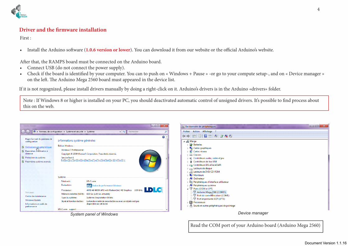
First :
• Install the Arduino software (1.0.6 version or lower). You can download it from our website or the official Arduino’s website.
After that, the RAMPS board must be connected on the Arduino board.• Connect USB (do not connect the power supply). • Check if the board is identified by your computer. You can to push on « Windows + Pause » -or go to your compute setup-, and on « Device manager »
on the left. The Arduino Mega 2560 board must appeared in the device list.
System panel of Windows Device manager
Read the COM port of your Arduino board (Arduino Mega 2560)
Driver and the firmware installation
Note : If Windows 8 or higher is installed on your PC, you should deactivated automatic control of unsigned drivers. It’s possible to find process about this on the web.
If it is not regognized, please install drivers manually by doing a right-click on it. Arduino’s drivers is in the Arduino «drivers» folder.
Document Version 1.1.16Document Version 1.1.16
/ 5
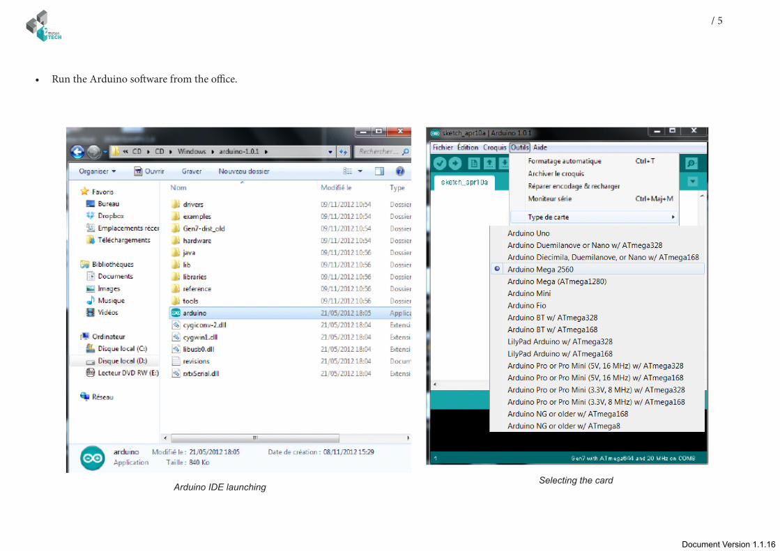
• Run the Arduino software from the office.
Arduino IDE launchingSelecting the card

6
Document Version 1.1.16
Document Version 1.1.16Document Version 1.1.16
/ 7
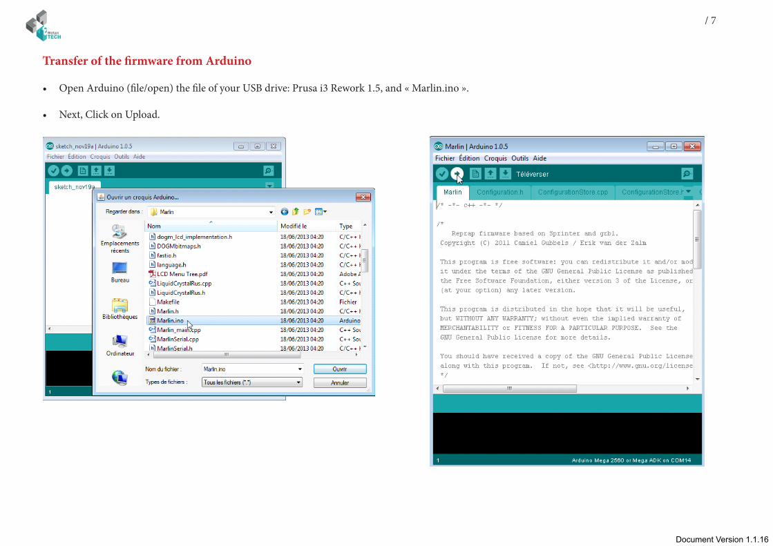
• Open Arduino (file/open) the file of your USB drive: Prusa i3 Rework 1.5, and « Marlin.ino ».
• Next, Click on Upload.
Transfer of the firmware from Arduino

8
Document Version 1.1.16
Connect the RAMPS board to the power supply 12v and respect polarity.
Before to begin this tutorial, you have to get:
• The electronic and mechanic parts (see the assembly instruc-tions);
• The board need to be identified by your computer; • The firmware is download.
First we are going to settle the host software (Repetier host) com-munication.
Interface of Repetier-Host and open of Printer settings
Connection to Repetier-Host

Document Version 1.1.16Document Version 1.1.16
/ 9
Choice of the COM port
10
Document Version 1.1.16
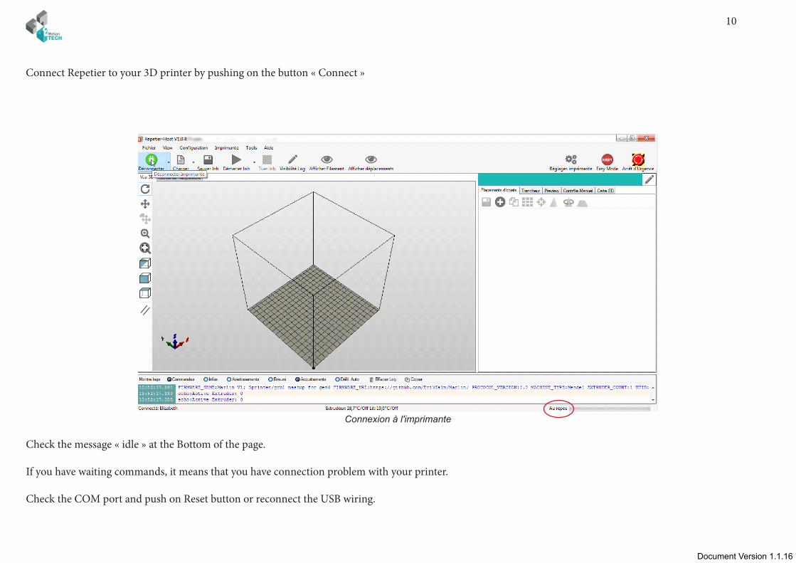
Connect Repetier to your 3D printer by pushing on the button « Connect »
Connexion à l'imprimante
Check the message « idle » at the Bottom of the page.
If you have waiting commands, it means that you have connection problem with your printer.
Check the COM port and push on Reset button or reconnect the USB wiring.
Document Version 1.1.16Document Version 1.1.16
/ 11
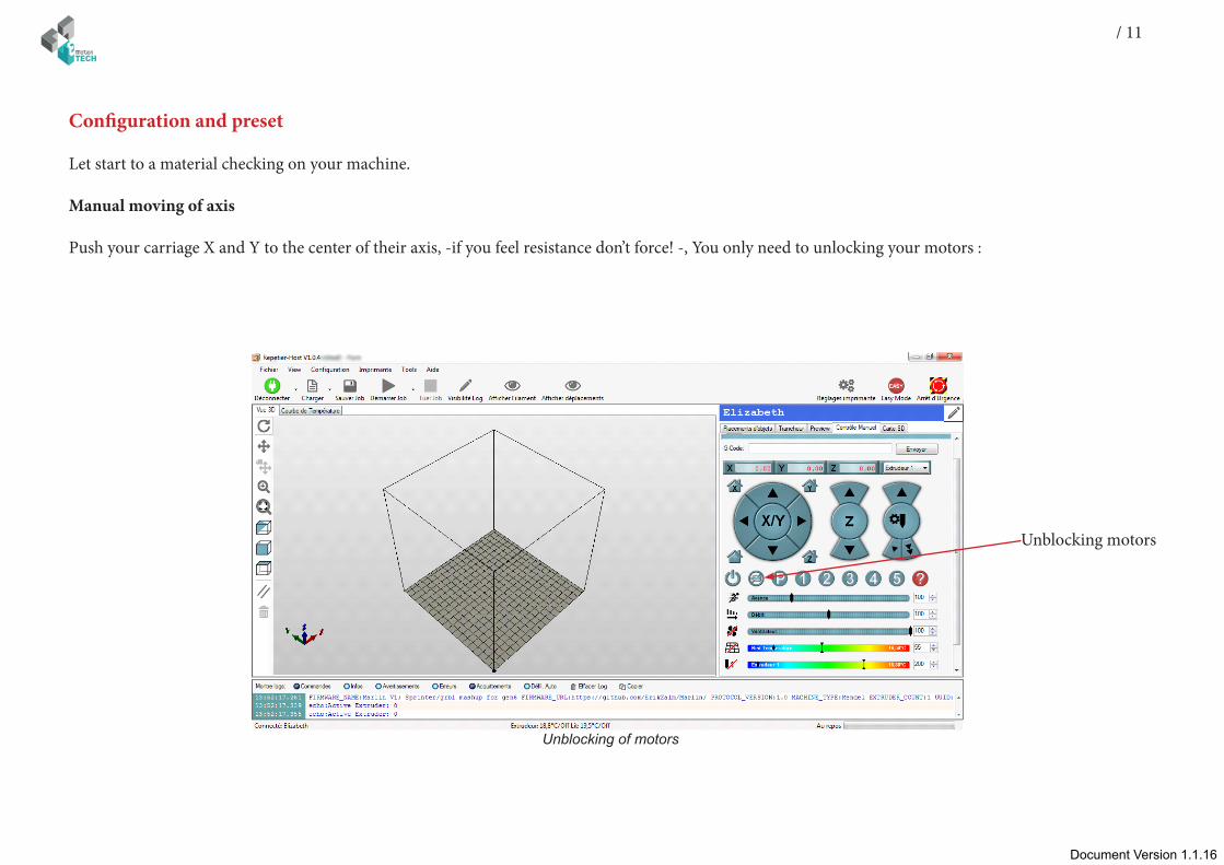
Configuration and preset
Let start to a material checking on your machine.
Manual moving of axis
Push your carriage X and Y to the center of their axis, -if you feel resistance don’t force! -, You only need to unlocking your motors :
Unblocking of motors
Unblocking motors
12
Document Version 1.1.16
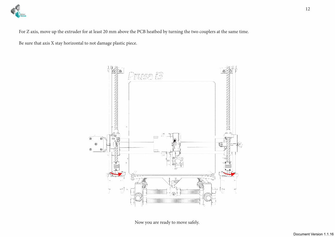
For Z axis, move up the extruder for at least 20 mm above the PCB heatbed by turning the two couplers at the same time.
Be sure that axis X stay horizontal to not damage plastic piece.
Now you are ready to move safely.
Document Version 1.1.16Document Version 1.1.16
/ 13
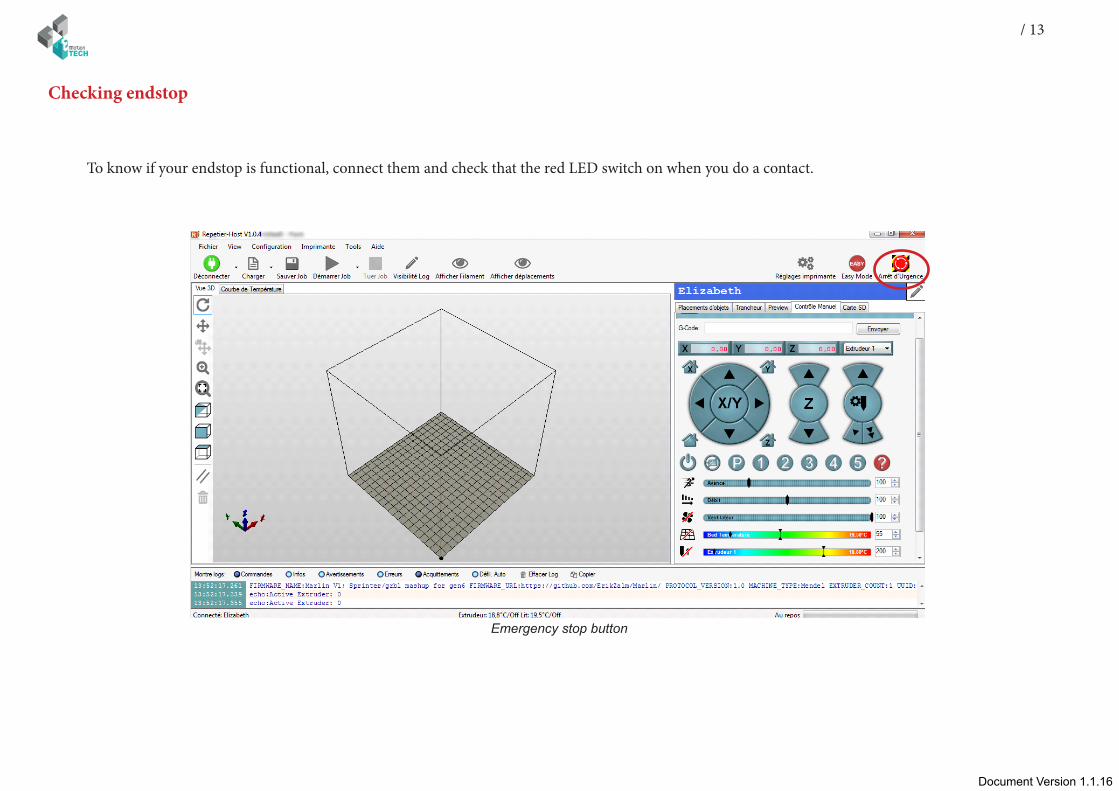
To know if your endstop is functional, connect them and check that the red LED switch on when you do a contact.
Emergency stop button
Checking endstop
14
Document Version 1.1.16
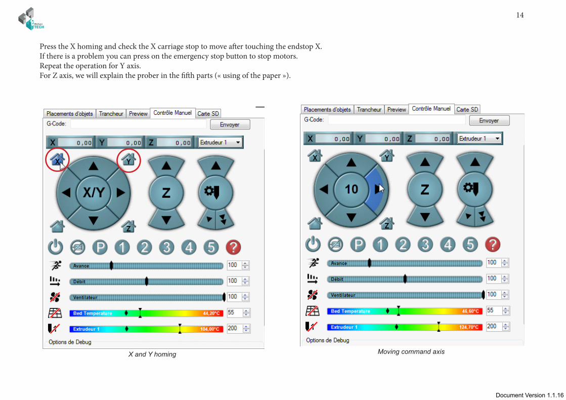
Press the X homing and check the X carriage stop to move after touching the endstop X.If there is a problem you can press on the emergency stop button to stop motors. Repeat the operation for Y axis.For Z axis, we will explain the prober in the fifth parts (« using of the paper »).
X and Y homing Moving command axis
Document Version 1.1.16Document Version 1.1.16
/ 15
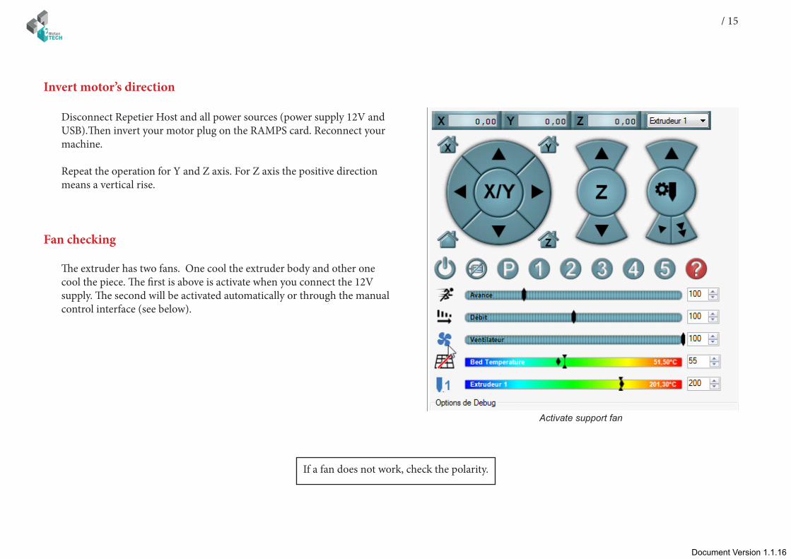
Disconnect Repetier Host and all power sources (power supply 12V and USB).Then invert your motor plug on the RAMPS card. Reconnect your machine.
Repeat the operation for Y and Z axis. For Z axis the positive direction means a vertical rise.
Activate support fan
If a fan does not work, check the polarity.
Invert motor’s direction
The extruder has two fans. One cool the extruder body and other one cool the piece. The first is above is activate when you connect the 12V supply. The second will be activated automatically or through the manual control interface (see below).
Fan checking
16
Document Version 1.1.16
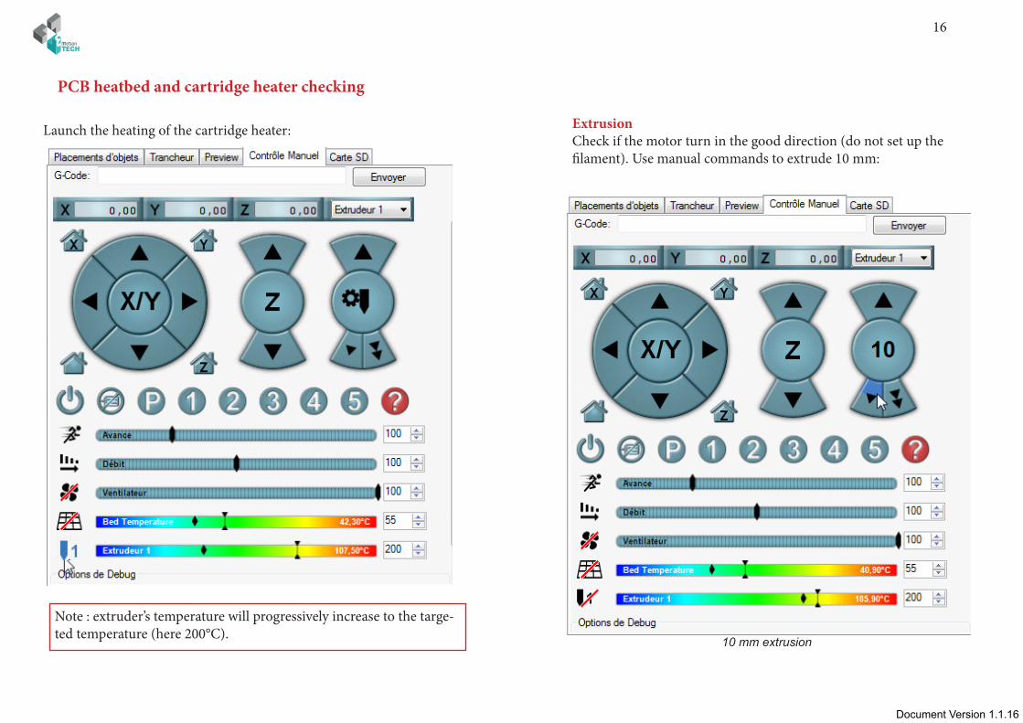
Launch the heating of the cartridge heater: ExtrusionCheck if the motor turn in the good direction (do not set up the filament). Use manual commands to extrude 10 mm:
10 mm extrusion
PCB heatbed and cartridge heater checking
Note : extruder’s temperature will progressively increase to the targe-ted temperature (here 200°C).

Document Version 1.1.16Document Version 1.1.16
/ 17
If it is necessary, invert the direction connection of the motor connector on RAMPS board.
Launch the heating according to the sort of plastic filament:
• For PLA : from 200° to 210° and 50° for the PCB heatbed (Cover the plate with Polyimide for a better adhesion)
• For ABS : from 230° to 250° and 90° for the PCB heatbed, (spread ABS juice*, on the plate cover of polyimide, with a brush to have a better adhesion)
* ABS juice: Dissolve ABS filament in some acetone to obtain a liquid mixture.
For instance : In a glass, pour 10 cl of acetone and add 10cm of ABS filament, thicken with more filament if the adhesion is not sufficient.
Insert plastic filament 1.75 mm in the extruder by pushing on the Extrudeur Idler (fixed on a spring) to free access to the filament.
When you have reach the temperature, use manual command to extrude.
Check that your hotend have no leak, if it is, it means that you had not well build or tighten your extruder.
Check also that the drive wheel well train the filament continuously and without slippage. In a first time, you can re-tighten the spring.
Cut the filament extremely beveled to insert easily your filament in the extru-derPush
18
Document Version 1.1.16
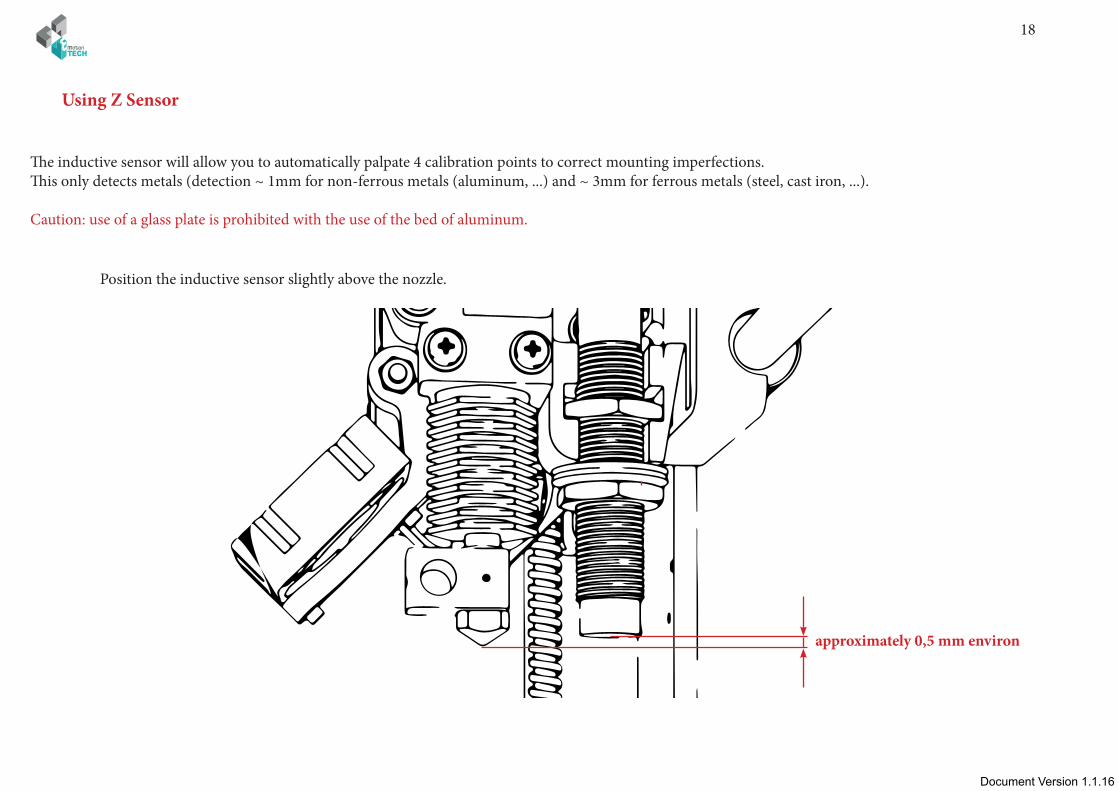
The inductive sensor will allow you to automatically palpate 4 calibration points to correct mounting imperfections.This only detects metals (detection ~ 1mm for non-ferrous metals (aluminum, ...) and ~ 3mm for ferrous metals (steel, cast iron, ...).
Caution: use of a glass plate is prohibited with the use of the bed of aluminum.
Using Z Sensor
Position the inductive sensor slightly above the nozzle.
approximately 0,5 mm environ
Document Version 1.1.16Document Version 1.1.16
/ 19
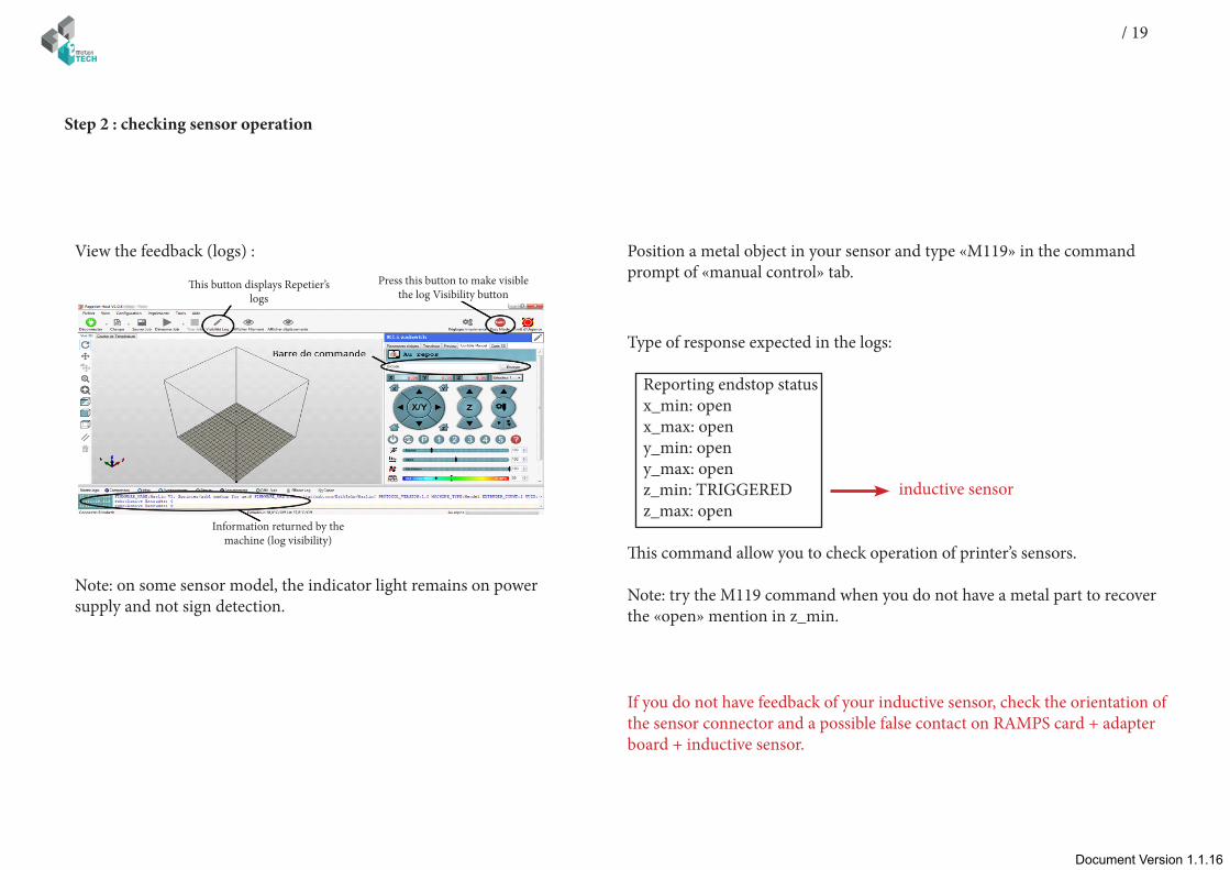
Step 2 : checking sensor operation
View the feedback (logs) : Position a metal object in your sensor and type «M119» in the command prompt of «manual control» tab.
Type of response expected in the logs:
Reporting endstop status x_min: open x_max: open y_min: open y_max: open z_min: TRIGGERED z_max: open
This command allow you to check operation of printer’s sensors.
Note: try the M119 command when you do not have a metal part to recover the «open» mention in z_min.
If you do not have feedback of your inductive sensor, check the orientation of the sensor connector and a possible false contact on RAMPS card + adapter board + inductive sensor.
Note: on some sensor model, the indicator light remains on power supply and not sign detection.
inductive sensor
This button displays Repetier’s logs
Press this button to make visible the log Visibility button
Information returned by the machine (log visibility)
20
Document Version 1.1.16
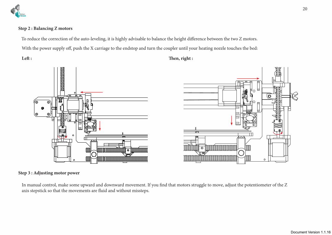
To reduce the correction of the auto-leveling, it is highly advisable to balance the height difference between the two Z motors.
Step 2 : Balancing Z motors
With the power supply off, push the X carriage to the endstop and turn the coupler until your heating nozzle touches the bed:
Left : Then, right :
In manual control, make some upward and downward movement. If you find that motors struggle to move, adjust the potentiometer of the Z axis stepstick so that the movements are fluid and without missteps.
Step 3 : Adjusting motor power

Document Version 1.1.16Document Version 1.1.16
/ 21
Note * : standard sheet of paper (80 grs)
Step 4 : Z-Axis calibrating
1- Initialize X and Y axes by clicking the house icon
3 -Place a paper’s sheet under the heating head.
4 - Using the cursor dedicated to the Z axis, move it down until the paper is slightly blocked.
What is the target ?To properly calculate the correction of the auto-leveling we need to determine the difference of our printhead with the heating bed when palpated with our sensor.Note: This difference is therefore a negative value beacause it will lower the heating head of measurement recorded up to get the point Z = 0.
Paper *
2 - Send the following GCODE command : G92 Z100This sets the current Z axis point to Z = 100 so it can move down.
Note: the heat tends to influence the sensor signals, it is best to calibrate thereof taking care beforehand that the heating elements are already at target temperature.
22
Document Version 1.1.16
9 - To set the value of the specified gap type the following command :
In our previous example :M851 Z-0.49
Note: Replacing «-0.49» with the value you received without forget to mention the «-» sign.
10 - Type the «M500» command to save permanently in the memory of your machine.
5 - Type the «G92 Z0» command to set the point Z = 0 of your printer
6 - Using the arrows, move your Z axis 30mm upward, so you will be at Z = 30
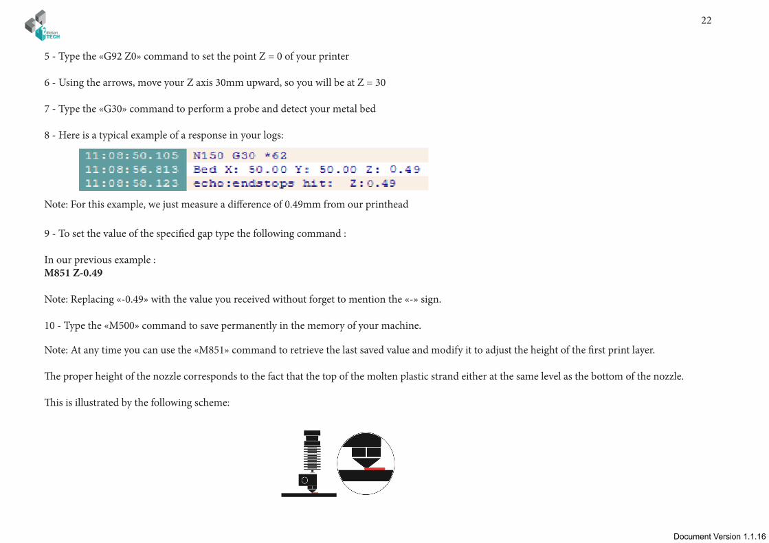
7 - Type the «G30» command to perform a probe and detect your metal bed
8 - Here is a typical example of a response in your logs:
Note: For this example, we just measure a difference of 0.49mm from our printhead
Note: At any time you can use the «M851» command to retrieve the last saved value and modify it to adjust the height of the first print layer.
The proper height of the nozzle corresponds to the fact that the top of the molten plastic strand either at the same level as the bottom of the nozzle.
This is illustrated by the following scheme:
Document Version 1.1.16Document Version 1.1.16
/ 23
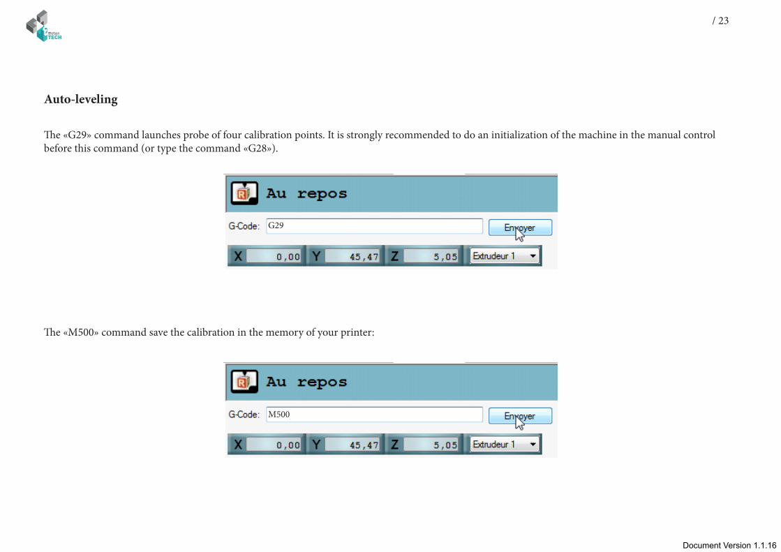
The «G29» command launches probe of four calibration points. It is strongly recommended to do an initialization of the machine in the manual control before this command (or type the command «G28»).
Auto-leveling
G29
The «M500» command save the calibration in the memory of your printer:
M500

24ANNEX
Document Version 1.1.16
ANNEX
Document Version 1.1.16Document Version 1.1.16
/ 25ANNEX
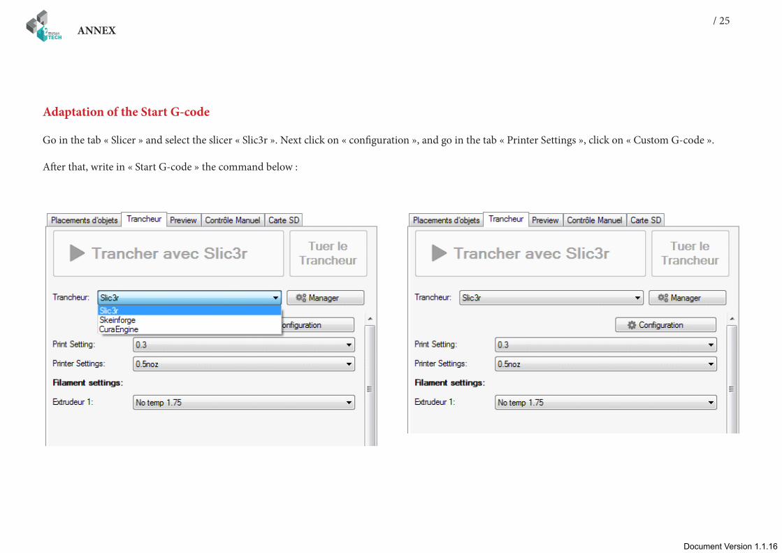
Adaptation of the Start G-code
Go in the tab « Slicer » and select the slicer « Slic3r ». Next click on « configuration », and go in the tab « Printer Settings », click on « Custom G-code ».
After that, write in « Start G-code » the command below :
26ANNEX
Document Version 1.1.16
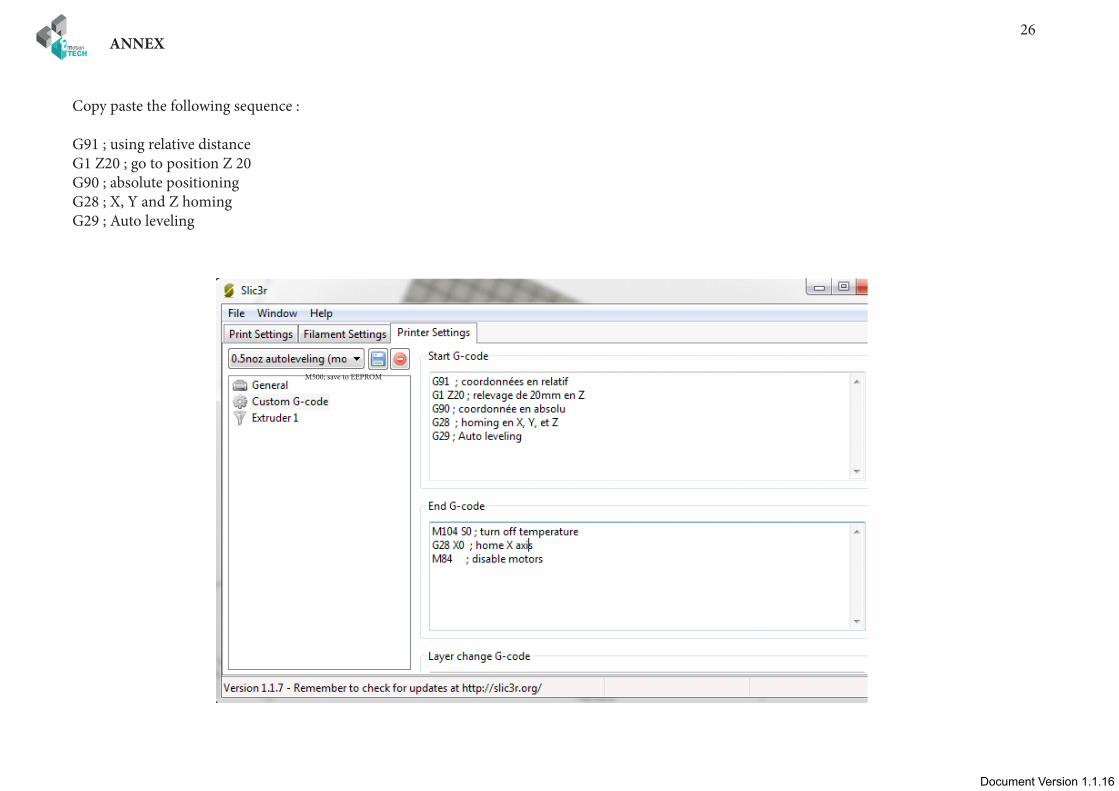
Copy paste the following sequence :
G91 ; using relative distanceG1 Z20 ; go to position Z 20G90 ; absolute positioningG28 ; X, Y and Z homingG29 ; Auto leveling
M500; save to EEPROM
Document Version 1.1.16Document Version 1.1.16
/ 27ANNEX
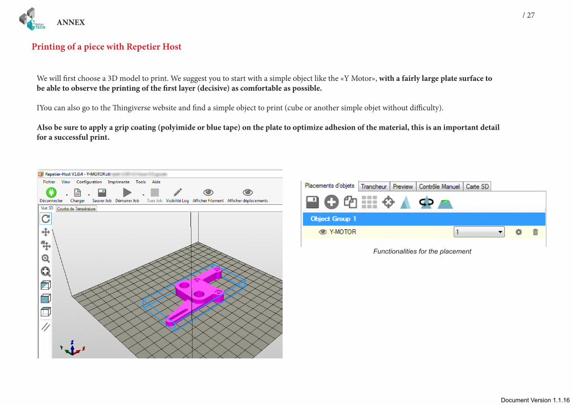
Functionalities for the placement
We will first choose a 3D model to print. We suggest you to start with a simple object like the «Y Motor», with a fairly large plate surface to be able to observe the printing of the first layer (decisive) as comfortable as possible.
IYou can also go to the Thingiverse website and find a simple object to print (cube or another simple objet without difficulty).
Also be sure to apply a grip coating (polyimide or blue tape) on the plate to optimize adhesion of the material, this is an important detail for a successful print.
Printing of a piece with Repetier Host
28ANNEX
Document Version 1.1.16
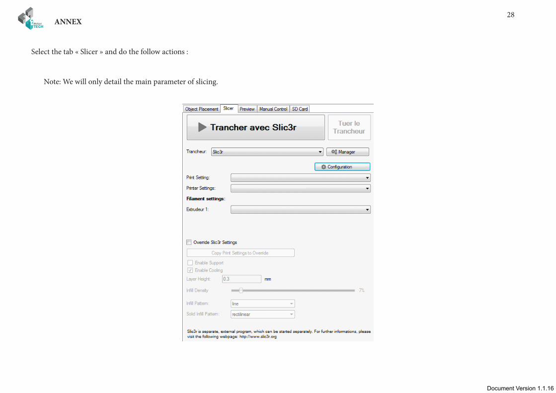
Select the tab « Slicer » and do the follow actions :
Note: We will only detail the main parameter of slicing.

Document Version 1.1.16Document Version 1.1.16
/ 29ANNEX
Infill settings
30ANNEX
Document Version 1.1.16
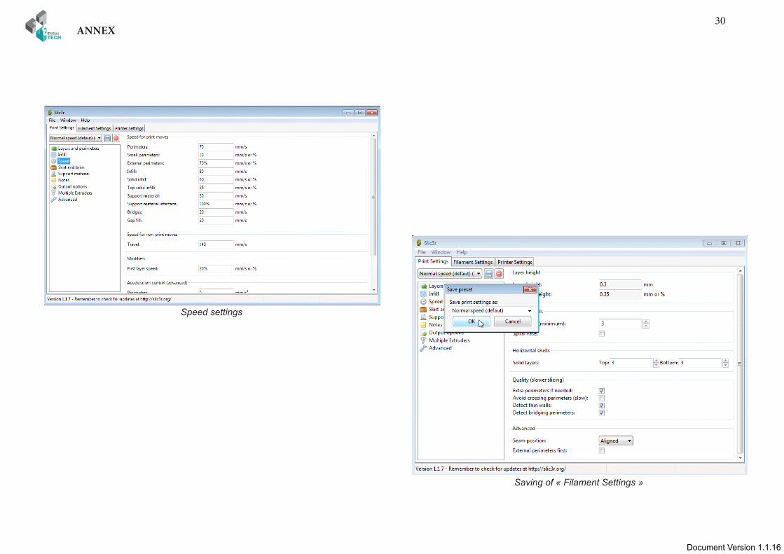
Speed settings
Saving of « Filament Settings »
Document Version 1.1.16Document Version 1.1.16
/ 31ANNEX
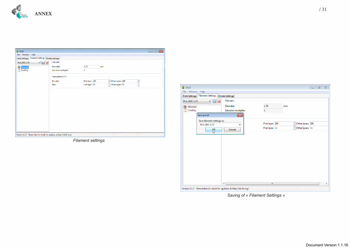
Filament settings
Saving of « Filament Settings »
55 55
55 55
32ANNEX
Document Version 1.1.16
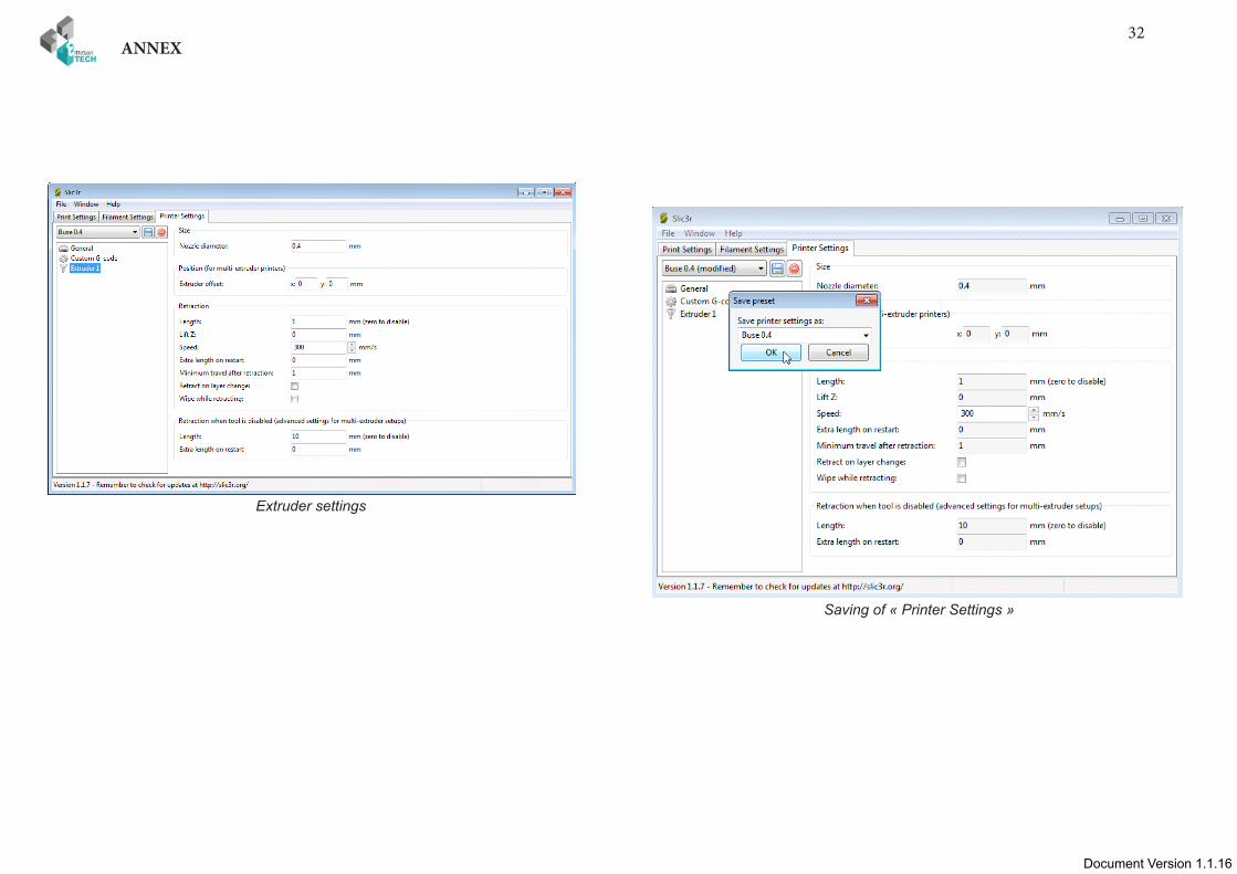
Extruder settings
Saving of « Printer Settings »
Document Version 1.1.16Document Version 1.1.16
/ 33ANNEX
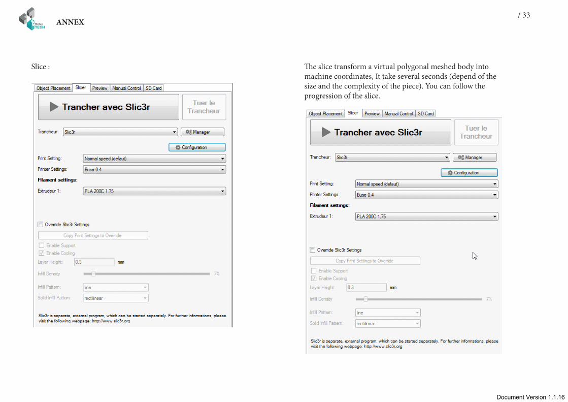
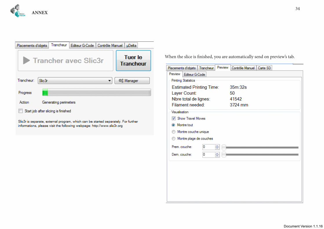
Slice : The slice transform a virtual polygonal meshed body into machine coordinates, It take several seconds (depend of the size and the complexity of the piece). You can follow the progression of the slice.
34ANNEX
Document Version 1.1.16
When the slice is finished, you are automatically send on preview’s tab.
Document Version 1.1.16Document Version 1.1.16
/ 35ANNEX
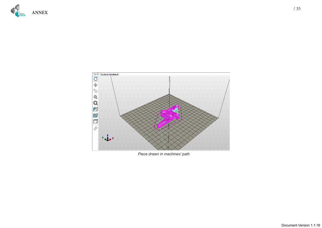
Piece drawn in machines’ path

36ANNEX
Document Version 1.1.16
Now you can start the print :
Congratulation for your first print !!
Document Version 1.1.16Document Version 1.1.16
/ 37ANNEX
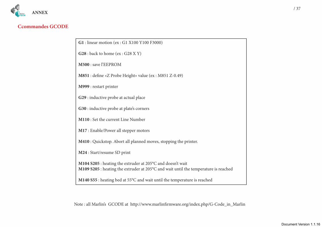
Ccommandes GCODE
G1 : linear motion (ex : G1 X100 Y100 F3000)
G28 : back to home (ex : G28 X Y)
M500 : save l’EEPROM
M851 : define «Z Probe Height» value (ex : M851 Z-0.49)
M999 : restart printer
G29 : inductive probe at actual place
G30 : inductive probe at plate’s corners
M110 : Set the current Line Number
M17 : Enable/Power all stepper motors
M410 : Quickstop. Abort all planned moves, stopping the printer.
M24 : Start/resume SD print
M104 S205 : heating the extruder at 205°C and doesn’t waitM109 S205 : heating the extruder at 205°C and wait until the temperature is reached
M140 S55 : heating bed at 55°C and wait until the temperature is reached
Note : all Marlin’s GCODE at http://www.marlinfirmware.org/index.php/G-Code_in_Marlin
38ANNEX
Document Version 1.1.16
MaintenanceA monthly maintenance of the 3D printer is recommended.
Below are some recommendations:
with the help of a brush, dust the following elements :• RAMPS board• stepsticks heatsinks• all fans and ensure that airflow is not blocked• coldend of the print head
- clean the print head with the help of the guide dedicated to the Hexagon print head, here is the link: :http://data.emotion-tech.com/highlights_en/Hexagon%20-%20Hotend-guide-v1.1.pdf
- clean the drive wheel’s teeth with the aid of a needle, the end of a tweezers or a cutter blade
- check the tightening of each screw equipping the 3D printer
-lubricate all mechanical transmission elements with multipurpose grease or PTFE based oil spray(avoid WD40 product that has a tendency to be too aggressive for the mechanical elements)
RecommandationsShut down the 3D printer : After printing, if you want to turn off the machine, wait until the print head has cooled to room temperature to ensure that the print head does not clog.
Transport : If you have to move the machine by car or other means of transport, it is recommended to unplug stepper motors off the Teensylu board to avoid damaging components.
Troubleshooting : A FAQ is available for the Prusa i3 Rework 1.5 on our website in the «Support» section, do not hesitate to consult it if you are having trouble with your machine, most failures are resolved through this tool, do not deprive yourself !

Document Version 1.1.16Document Version 1.1.16
/ 39ANNEX
CONGRATULATION !
Your first print is a success !

40ANNEX
Document Version 1.1.16
Thank you for choosing Prusa i3 Rework rev. 1.5
www.reprap-3d-printer.com