assembly instructions - data.emotion-tech.com · prusa i3 assembly instructions 5 i. prusa mendel...
TRANSCRIPT
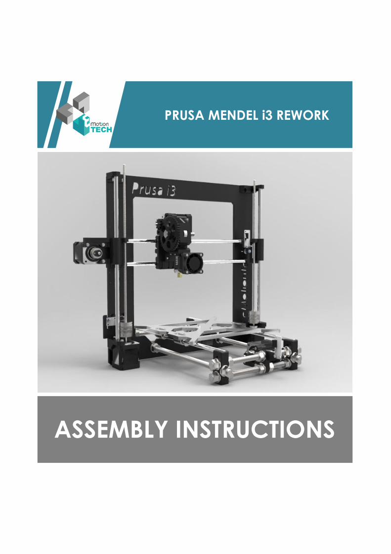
ASSEMBLY INSTRUCTIONS
PRUSA MENDEL i3 REWORK
iiiiiiiiirdfiiiiiRrrREWREWORK
Prusa i3 assembly instructions
2
Introduction
Purpose :
To provide a visual guide needed to build a Prusa Mendel i3 3D Printer.
Publisher :
eMotion Tech – http://www.Reprap-France.com
Nhat Tan NGUYEN – [email protected]
Sources :
Prusa Mendel i3 EiNSTeiN VARIANT -http://reprap.org/wiki/Prusa_i3_Build_Manual#EiNSTeiN_VARIANT
Modified extruder designed by ch1t0 - http://www.thingiverse.com/ch1t0/designs
Photo credits :
Images and 3D illustrations made by http://www.emotion-tech.com
RAMPS from the websitehttp://www.tylercrumpton.com
Wiring from the wiki http://reprap.orgtranslated by Yann CLEMENT
Licensing :
Prusa i3 : GPL (http://reprap.org/wiki/GPL)
This document : GPL
Prusa i3 assembly instructions
3
Table of contents
Introduction ........................................................................................................................................................ 2
I. Prusa Mendel i3 presentation ....................................................................................................................... 5
II. Bill of materials .............................................................................................................................................. 6
A. Printed Parts .......................................................................................................................................... 6
B. Extruder ................................................................................................................................................. 7
C. Smooth and threaded rods .................................................................................................................... 7
D. Mechanical parts ................................................................................................................................... 8
E. Heated bed ............................................................................................................................................ 8
F. Electronics .............................................................................................................................................. 9
G. Screws, nuts and washers ...................................................................................................................... 9
H. Aluminium frame ................................................................................................................................. 10
III. Mechanical assembly .................................................................................................................................. 11
A. Y-axis assembly .................................................................................................................................... 11
1. Heated bed mount ................................................................................................................... 11
2. Transverse parts ....................................................................................................................... 11
3. Assembly with the longitudinal parts ....................................................................................... 14
B. X-axis assembly .................................................................................................................................... 15
1. X End Idler & X End Motor ........................................................................................................ 15
2. X Carriage ................................................................................................................................. 17
3. X-Axis assembly ........................................................................................................................ 18
C. Connecting X-axis and Z-axis ............................................................................................................... 19
D. Motor assembly ................................................................................................................................... 20
1. Z-axis ......................................................................................................................................... 20
2. Y-axis ......................................................................................................................................... 21
3. X-axis ........................................................................................................................................ 22
E. Mechanical frame assembly ................................................................................................................ 23
F. X and Y-axis motions ............................................................................................................................ 24
1. X-axis belt ................................................................................................................................. 24
2. Y-axis belt ................................................................................................................................. 24
IV. Heated bed assembly .................................................................................................................................. 26
A. Thermistors assembly .......................................................................................................................... 26
B. Heated bed assembly .......................................................................................................................... 26
V. Extruder assembly ....................................................................................................................................... 28
A. Extruder assembly ............................................................................................................................... 28
B. Connecting to X-axis ............................................................................................................................ 30
C. Nozzle height adjustment .................................................................................................................... 32
VI. Electronics and wiring ................................................................................................................................. 33
Prusa i3 assembly instructions
4
A. Mounting electronics ........................................................................................................................... 33
B. Wiring .................................................................................................................................................. 34
1. Endstop wiring .......................................................................................................................... 35
2. Motors wiring ........................................................................................................................... 35
3. Resistor and PCB heatbed wiring ............................................................................................. 35
4. Thermistors wiring ................................................................................................................... 35
5. Fans wiring................................................................................................................................ 35
6. Power supply wiring ................................................................................................................. 36
Prusa i3 assembly instructions
5
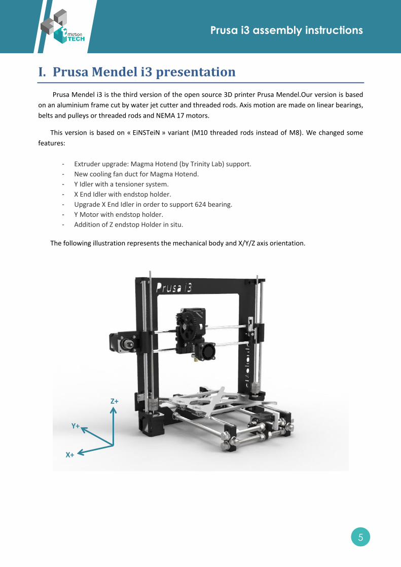
I. Prusa Mendel i3 presentation
Prusa Mendel i3 is the third version of the open source 3D printer Prusa Mendel.Our version is based
on an aluminium frame cut by water jet cutter and threaded rods. Axis motion are made on linear bearings,
belts and pulleys or threaded rods and NEMA 17 motors.
This version is based on « EiNSTeiN » variant (M10 threaded rods instead of M8). We changed some
features:
- Extruder upgrade: Magma Hotend (by Trinity Lab) support.
- New cooling fan duct for Magma Hotend.
- Y Idler with a tensioner system.
- X End Idler with endstop holder.
- Upgrade X End Idler in order to support 624 bearing.
- Y Motor with endstop holder.
- Addition of Z endstop Holder in situ.
The following illustration represents the mechanical body and X/Y/Z axis orientation.
Z+
Y+
X+
Prusa i3 assembly instructions
6
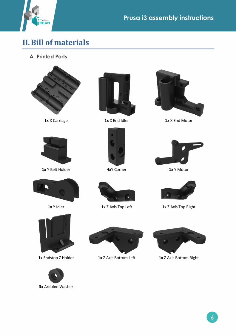
II. Bill of materials
A. Printed Parts
1x X Carriage
1x X End Idler
1x X End Motor
1x Y Belt Holder
4xY Corner
1x Y Motor
1x Y Idler
1x Z Axis Top Left
1x Z Axis Top Right
1x Endstop Z Holder
1x Z Axis Bottom Left
1x Z Axis Bottom Right
3x Arduino Washer
Prusa i3 assembly instructions
7
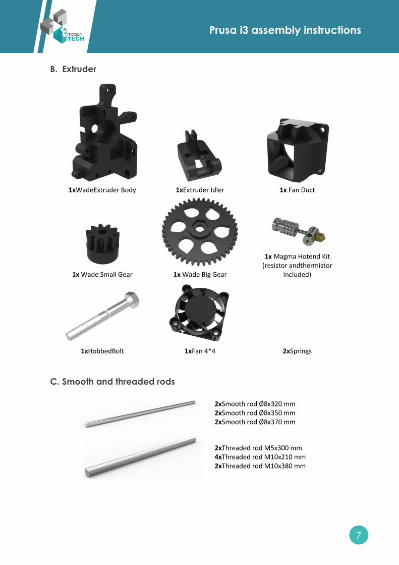
B. Extruder
1xWadeExtruder Body
1xExtruder Idler
1x Fan Duct
1x Wade Small Gear
1x Wade Big Gear
1x Magma Hotend Kit
(resistor andthermistor included)
1xHobbedBolt
1xFan 4*4 2xSprings
C. Smooth and threaded rods
2xSmooth rod Ø8x320 mm 2xSmooth rod Ø8x350 mm 2xSmooth rod Ø8x370 mm
2xThreaded rod M5x300 mm 4xThreaded rod M10x210 mm 2xThreaded rod M10x380 mm
Prusa i3 assembly instructions
8
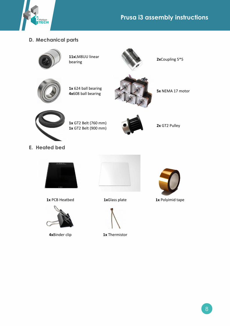
D. Mechanical parts
11xLM8UU linear bearing
2xCoupling 5*5
1x 624 ball bearing 4x608 ball bearing
5x NEMA 17 motor
1x GT2 Belt (760 mm) 1x GT2 Belt (900 mm)
2x GT2 Pulley
E. Heated bed
1x PCB Heatbed
1xGlass plate
1x Polyimid tape
4xBinder clip
1x Thermistor
Prusa i3 assembly instructions
9
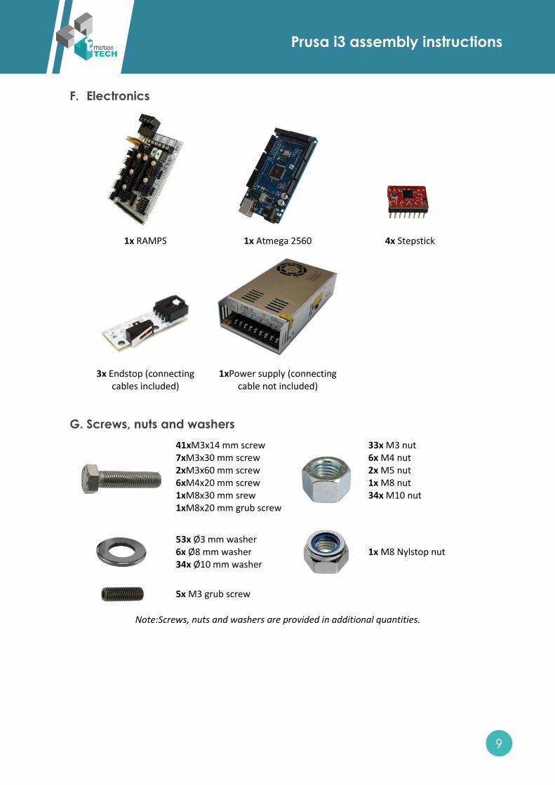
F. Electronics
1x RAMPS
1x Atmega 2560
4x Stepstick
3x Endstop (connecting
cables included)
1xPower supply (connecting
cable not included)
G. Screws, nuts and washers
41xM3x14 mm screw 7xM3x30 mm screw 2xM3x60 mm screw 6xM4x20 mm screw 1xM8x30 mm srew 1xM8x20 mm grub screw
33x M3 nut 6x M4 nut 2x M5 nut 1x M8 nut 34x M10 nut
53x Ø3 mm washer 6x Ø8 mm washer 34x Ø10 mm washer
1x M8 Nylstop nut
5x M3 grub screw
Note:Screws, nuts and washers are provided in additional quantities.
Prusa i3 assembly instructions
10
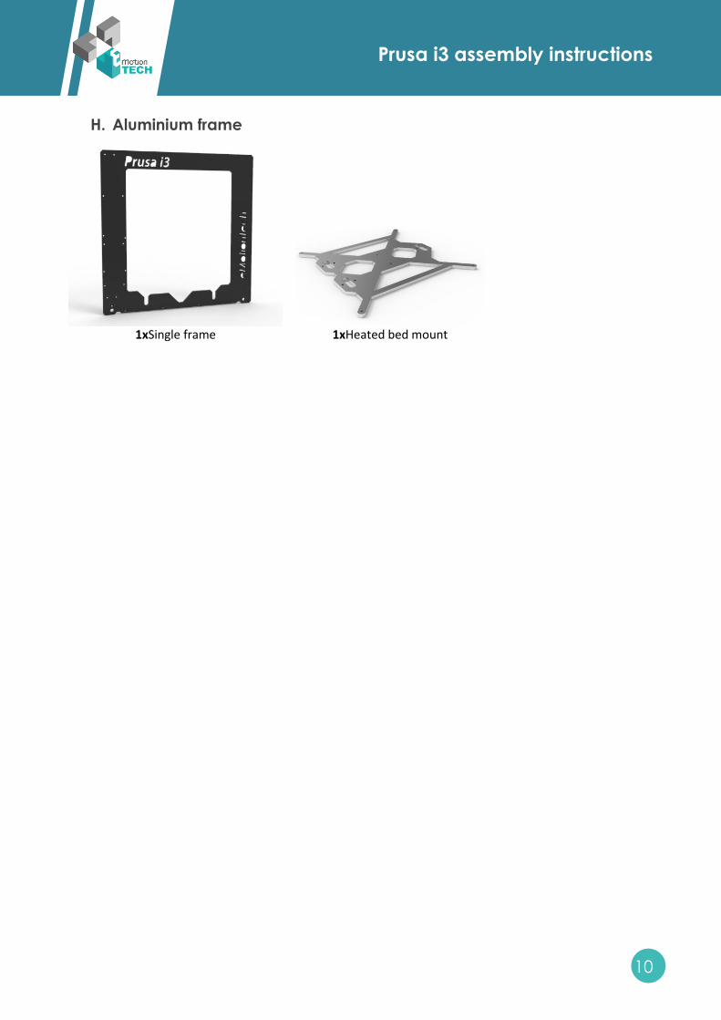
H. Aluminium frame
1xSingle frame
1xHeated bed mount
Prusa i3 assembly instructions
11
III. Mechanical assembly
A. Y-axis assembly
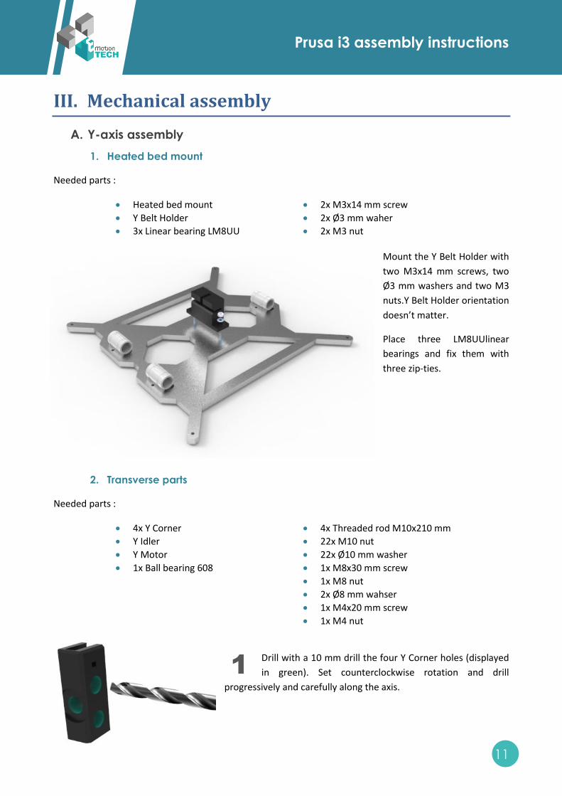
1. Heated bed mount
Needed parts :
Heated bed mount
Y Belt Holder
3x Linear bearing LM8UU
2x M3x14 mm screw
2x Ø3 mm waher
2x M3 nut
Mount the Y Belt Holder with
two M3x14 mm screws, two
Ø3 mm washers and two M3
nuts.Y Belt Holder orientation
doesn’t matter.
Place three LM8UUlinear
bearings and fix them with
three zip-ties.
2. Transverse parts
Needed parts :
4x Y Corner
Y Idler
Y Motor
1x Ball bearing 608
4x Threaded rod M10x210 mm
22x M10 nut
22x Ø10 mm washer
1x M8x30 mm screw
1x M8 nut
2x Ø8 mm wahser
1x M4x20 mm screw
1x M4 nut
Drill with a 10 mm drill the four Y Corner holes (displayed
in green). Set counterclockwise rotation and drill
progressively and carefully along the axis.
1
Prusa i3 assembly instructions
12
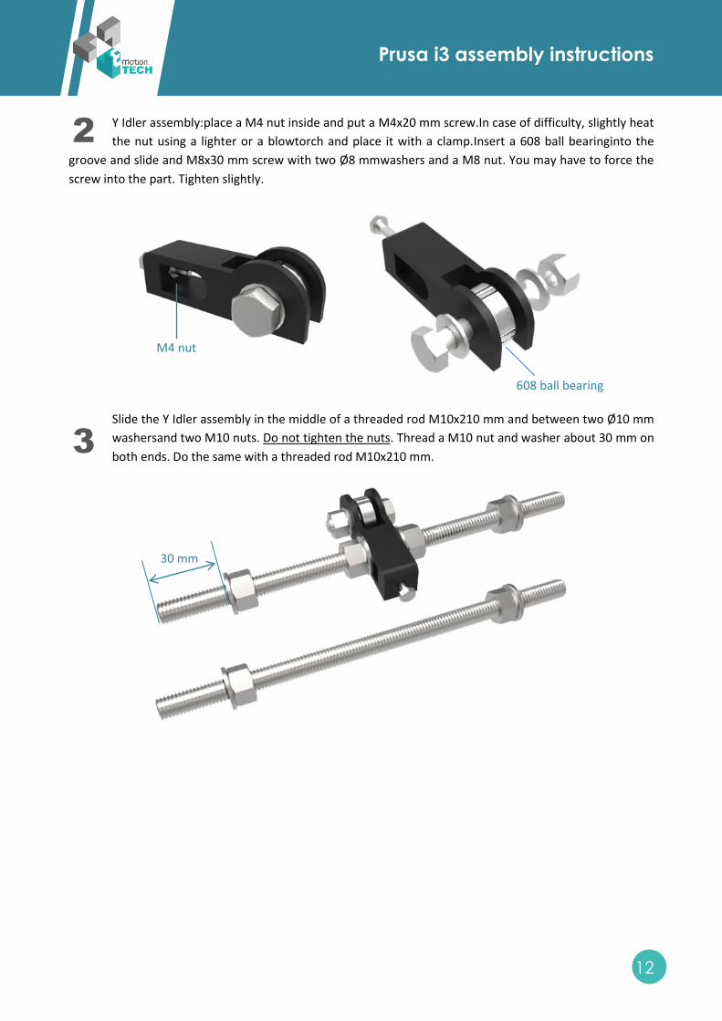
Y Idler assembly:place a M4 nut inside and put a M4x20 mm screw.In case of difficulty, slightly heat
the nut using a lighter or a blowtorch and place it with a clamp.Insert a 608 ball bearinginto the
groove and slide and M8x30 mm screw with two Ø8 mmwashers and a M8 nut. You may have to force the
screw into the part. Tighten slightly.
Slide the Y Idler assembly in the middle of a threaded rod M10x210 mm and between two Ø10 mm
washersand two M10 nuts. Do not tighten the nuts. Thread a M10 nut and washer about 30 mm on
both ends. Do the same with a threaded rod M10x210 mm.
2
3
M4 nut
608 ball bearing
30 mm

Prusa i3 assembly instructions
13
Slide two threaded rods M10x210 mm on the Y Motor and fix it with four M10 nuts and four Ø10
washers. Do not tighten the nuts.Thread a M10 nut and washer about 30 mm on both ends.
Take two Y Corners, the Y Idler assembly and the threaded rod M10x210 mm and fix them with four
Ø10 washers and four M10 nuts. Do the same with the Y Motor assembly with two Y Corners. In
both cases, adjust the distance between two Y corners (186 mm). Slightly tighten the nuts.
4
5
30 mm
186 mm
186 mm
Prusa i3 assembly instructions
14
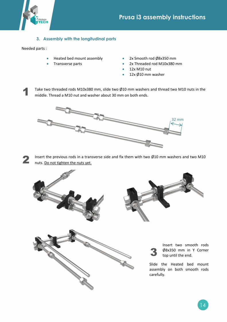
3. Assembly with the longitudinal parts
Needed parts :
Heated bed mount assembly
Transverse parts
2x Smooth rod Ø8x350 mm
2x Threaded rod M10x380 mm
12x M10 nut
12x Ø10 mm washer
Take two threaded rods M10x380 mm, slide two Ø10 mm washers and thread two M10 nuts in the
middle. Thread a M10 nut and washer about 30 mm on both ends.
Insert the previous rods in a transverse side and fix them with two Ø10 mm washers and two M10
nuts. Do not tighten the nuts yet.
Insert two smooth rods Ø8x350 mm in Y Corner top until the end.
Slide the Heated bed mount assembly on both smooth rods carefully.
1
2
3
32 mm
Prusa i3 assembly instructions
15
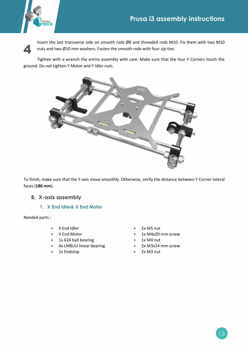
Insert the last transverse side on smooth rods Ø8 and threaded rods M10. Fix them with two M10
nuts and two Ø10 mm washers. Fasten the smooth rods with four zip-ties.
Tighten with a wrench the entire assembly with care. Make sure that the four Y Corners touch the
ground. Do not tighten Y Motor and Y Idler nuts.
To finish, make sure that the Y-axis move smoothly. Otherwise, verify the distance between Y Corner lateral
faces (186 mm).
B. X-axis assembly
1. X End Idler& X End Motor
Needed parts :
X End Idler
X End Motor
1x 624 ball bearing
4x LM8UU linear bearing
1x Endstop
2x M5 nut
1x M4x20 mm screw
1x M4 nut
2x M3x14 mm screw
2x M3 nut
4
Prusa i3 assembly instructions
16
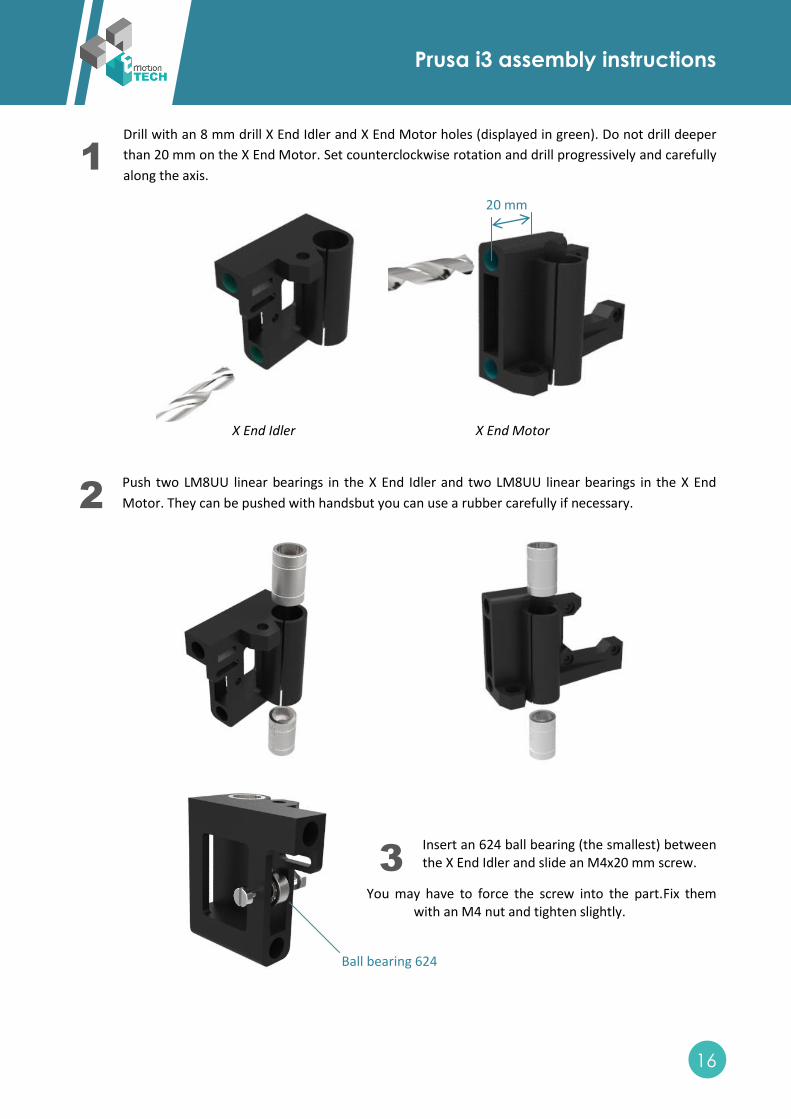
Drill with an 8 mm drill X End Idler and X End Motor holes (displayed in green). Do not drill deeper
than 20 mm on the X End Motor. Set counterclockwise rotation and drill progressively and carefully
along the axis.
X End Idler
X End Motor
Push two LM8UU linear bearings in the X End Idler and two LM8UU linear bearings in the X End
Motor. They can be pushed with handsbut you can use a rubber carefully if necessary.
Insert an 624 ball bearing (the smallest) between the X End Idler and slide an M4x20 mm screw.
You may have to force the screw into the part.Fix them with an M4 nut and tighten slightly.
1
2
3
Ball bearing 624
20 mm
Prusa i3 assembly instructions
17
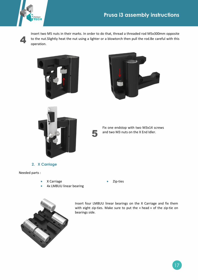
Insert two M5 nuts in their marks. In order to do that, thread a threaded rod M5x300mm opposite
to the nut.Slightly heat the nut using a lighter or a blowtorch then pull the rod.Be careful with this
operation.
Fix one endstop with two M3x14 screws and two M3 nuts on the X End Idler.
2. X Carriage
Needed parts :
X Carriage
4x LM8UU linear bearing
Zip-ties
Insert four LM8UU linear bearings on the X Carriage and fix them with eight zip-ties. Make sure to put the « head » of the zip-tie on bearings side.
4
5
Prusa i3 assembly instructions
18
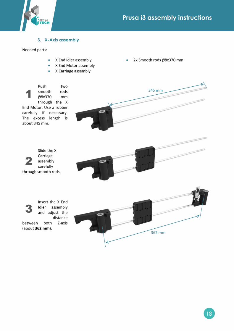
3. X-Axis assembly
Needed parts:
X End Idler assembly
X End Motor assembly
X Carriage assembly
2x Smooth rods Ø8x370 mm
Push two smooth rods Ø8x370 mm through the X
End Motor. Use a rubber carefully if necessary. The excess length is about 345 mm.
Slide the X Carriage assembly carefully
through smooth rods.
Insert the X End Idler assembly and adjust the
distance between both Z-axis (about 362 mm).
1
2
3
345 mm
362 mm
Prusa i3 assembly instructions
19
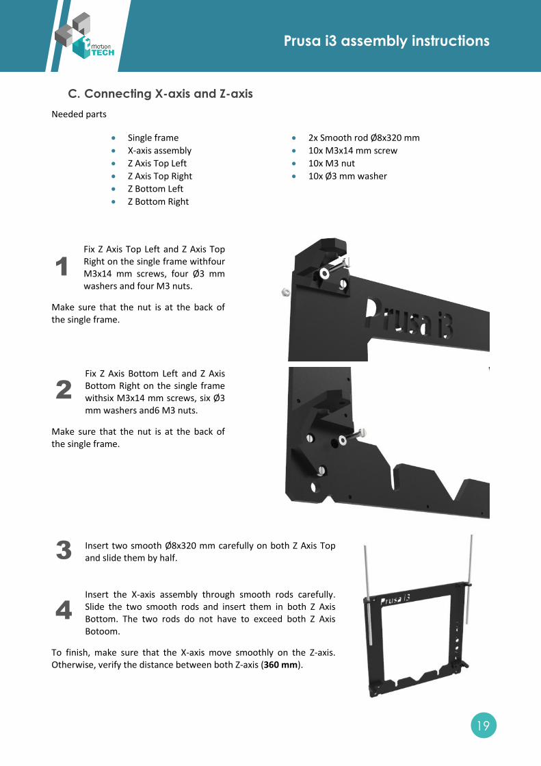
C. Connecting X-axis and Z-axis
Needed parts
Single frame
X-axis assembly
Z Axis Top Left
Z Axis Top Right
Z Bottom Left
Z Bottom Right
2x Smooth rod Ø8x320 mm
10x M3x14 mm screw
10x M3 nut
10x Ø3 mm washer
Fix Z Axis Top Left and Z Axis Top Right on the single frame withfour M3x14 mm screws, four Ø3 mm washers and four M3 nuts.
Make sure that the nut is at the back of the single frame.
Fix Z Axis Bottom Left and Z Axis Bottom Right on the single frame withsix M3x14 mm screws, six Ø3 mm washers and6 M3 nuts.
Make sure that the nut is at the back of the single frame.
Insert two smooth Ø8x320 mm carefully on both Z Axis Top and slide them by half. Insert the X-axis assembly through smooth rods carefully. Slide the two smooth rods and insert them in both Z Axis Bottom. The two rods do not have to exceed both Z Axis Botoom.
To finish, make sure that the X-axis move smoothly on the Z-axis. Otherwise, verify the distance between both Z-axis (360 mm).
1
2
3
4
Prusa i3 assembly instructions
20
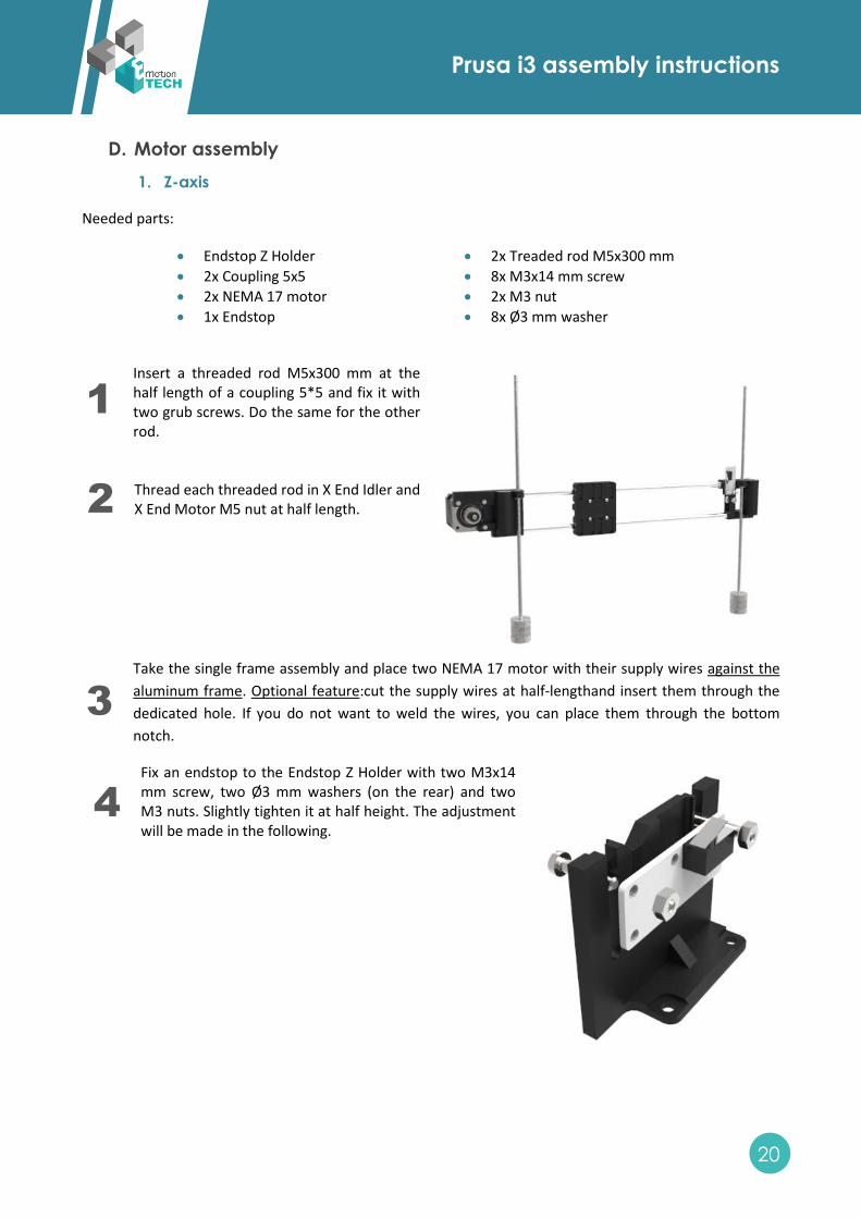
D. Motor assembly
1. Z-axis
Needed parts:
Endstop Z Holder
2x Coupling 5x5
2x NEMA 17 motor
1x Endstop
2x Treaded rod M5x300 mm
8x M3x14 mm screw
2x M3 nut
8x Ø3 mm washer
Insert a threaded rod M5x300 mm at the half length of a coupling 5*5 and fix it with two grub screws. Do the same for the other rod.
Thread each threaded rod in X End Idler and X End Motor M5 nut at half length.
Take the single frame assembly and place two NEMA 17 motor with their supply wires against the
aluminum frame. Optional feature:cut the supply wires at half-lengthand insert them through the
dedicated hole. If you do not want to weld the wires, you can place them through the bottom
notch.
Fix an endstop to the Endstop Z Holder with two M3x14 mm screw, two Ø3 mm washers (on the rear) and two M3 nuts. Slightly tighten it at half height. The adjustment will be made in the following.
1
2
3
4
Prusa i3 assembly instructions
21
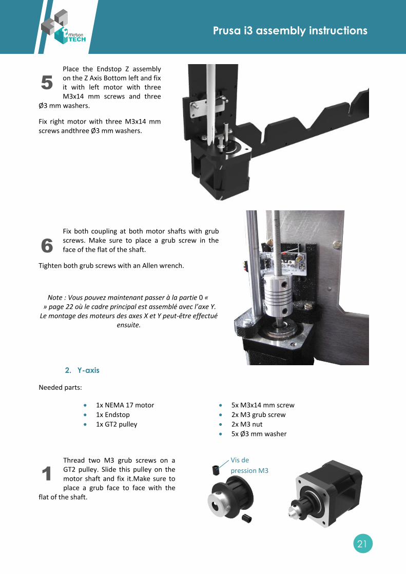
Place the Endstop Z assembly on the Z Axis Bottom left and fix it with left motor with three M3x14 mm screws and three
Ø3 mm washers.
Fix right motor with three M3x14 mm screws andthree Ø3 mm washers.
Fix both coupling at both motor shafts with grub screws. Make sure to place a grub screw in the face of the flat of the shaft.
Tighten both grub screws with an Allen wrench.
Note : Vous pouvez maintenant passer à la partie 0 « » page 22 où le cadre principal est assemblé avec l’axe Y. Le montage des moteurs des axes X et Y peut-être effectué
ensuite.
2. Y-axis
Needed parts:
1x NEMA 17 motor
1x Endstop
1x GT2 pulley
5x M3x14 mm screw
2x M3 grub screw
2x M3 nut
5x Ø3 mm washer
Thread two M3 grub screws on a GT2 pulley. Slide this pulley on the motor shaft and fix it.Make sure to place a grub face to face with the
flat of the shaft.
Vis de
pression M3
5
1
6
Prusa i3 assembly instructions
22
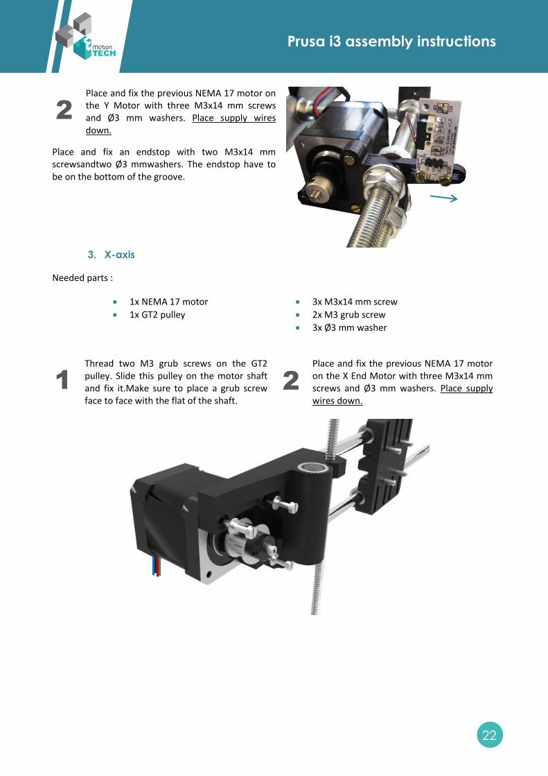
Place and fix the previous NEMA 17 motor on the Y Motor with three M3x14 mm screws and Ø3 mm washers. Place supply wires down.
Place and fix an endstop with two M3x14 mm screwsandtwo Ø3 mmwashers. The endstop have to be on the bottom of the groove.
3. X-axis
Needed parts :
1x NEMA 17 motor
1x GT2 pulley
3x M3x14 mm screw
2x M3 grub screw
3x Ø3 mm washer
Thread two M3 grub screws on the GT2 pulley. Slide this pulley on the motor shaft and fix it.Make sure to place a grub screw face to face with the flat of the shaft.
Place and fix the previous NEMA 17 motor on the X End Motor with three M3x14 mm screws and Ø3 mm washers. Place supply wires down.
2
1 2
Prusa i3 assembly instructions
23
E. Mechanical frame assembly
Needed parts :
Y-axis assembly
Single frame assembly
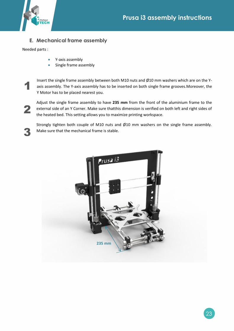
Insert the single frame assembly between both M10 nuts and Ø10 mm washers which are on the Y-
axis assembly. The Y-axis assembly has to be inserted on both single frame grooves.Moreover, the
Y Motor has to be placed nearest you.
Adjust the single frame assembly to have 235 mm from the front of the aluminium frame to the
external side of an Y Corner. Make sure thatthis dimension is verified on both left and right sides of
the heated bed. This setting allows you to maximize printing workspace.
Strongly tighten both couple of M10 nuts and Ø10 mm washers on the single frame assembly.
Make sure that the mechanical frame is stable.
1
2
3
235 mm
Prusa i3 assembly instructions
24
F. X and Y-axis motions
1. X-axis belt
Needed parts :
GT2 Belt (900 mm) Zip-ties
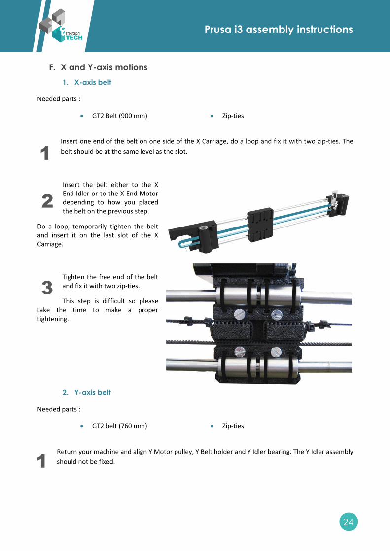
Insert one end of the belt on one side of the X Carriage, do a loop and fix it with two zip-ties. The
belt should be at the same level as the slot.
Insert the belt either to the X End Idler or to the X End Motor depending to how you placed the belt on the previous step.
Do a loop, temporarily tighten the belt and insert it on the last slot of the X Carriage.
Tighten the free end of the belt and fix it with two zip-ties.
This step is difficult so please take the time to make a proper tightening.
2. Y-axis belt
Needed parts :
GT2 belt (760 mm) Zip-ties
Return your machine and align Y Motor pulley, Y Belt holder and Y Idler bearing. The Y Idler assembly
should not be fixed.
1
2
3
1
Prusa i3 assembly instructions
25
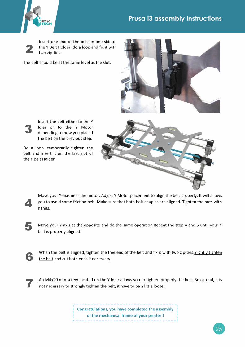
Insert one end of the belt on one side of the Y Belt Holder, do a loop and fix it with two zip-ties.
The belt should be at the same level as the slot.
Insert the belt either to the Y Idler or to the Y Motor depending to how you placed the belt on the previous step.
Do a loop, temporarily tighten the belt and insert it on the last slot of the Y Belt Holder.
Move your Y-axis near the motor. Adjust Y Motor placement to align the belt properly. It will allows
you to avoid some friction belt. Make sure that both bolt couples are aligned. Tighten the nuts with
hands.
Move your Y-axis at the opposite and do the same operation.Repeat the step 4 and 5 until your Y
belt is properly aligned.
When the belt is aligned, tighten the free end of the belt and fix it with two zip-ties.Slightly tighten
the belt and cut both ends if necessary.
An M4x20 mm screw located on the Y Idler allows you to tighten properly the belt. Be careful, it is
not necessary to strongly tighten the belt, it have to be a little loose.
Congratulations, you have completed the assembly
of the mechanical frame of your printer !
2
3
4
5
6
7
Prusa i3 assembly instructions
26
IV. Heated bed assembly
A. Thermistors assembly
Needed parts :
2x Thermistor
2x Connecting wire (2 pins)
Teflon wire (not included)
Polyimid tape
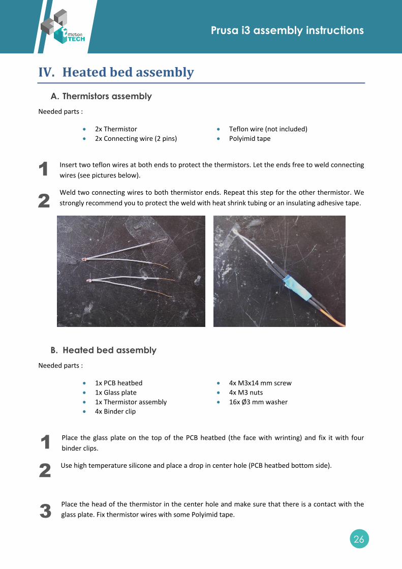
Insert two teflon wires at both ends to protect the thermistors. Let the ends free to weld connecting
wires (see pictures below).
Weld two connecting wires to both thermistor ends. Repeat this step for the other thermistor. We
strongly recommend you to protect the weld with heat shrink tubing or an insulating adhesive tape.
B. Heated bed assembly
Needed parts :
1x PCB heatbed
1x Glass plate
1x Thermistor assembly
4x Binder clip
4x M3x14 mm screw
4x M3 nuts
16x Ø3 mm washer
Place the glass plate on the top of the PCB heatbed (the face with wrinting) and fix it with four
binder clips.
Use high temperature silicone and place a drop in center hole (PCB heatbed bottom side).
Place the head of the thermistor in the center hole and make sure that there is a contact with the
glass plate. Fix thermistor wires with some Polyimid tape.
1
2
1
2
3
Prusa i3 assembly instructions
27
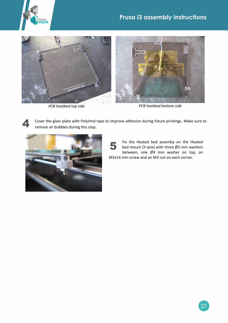
PCB heatbed top side
PCB heatbed bottom side
Cover the glass plate with Polyimid tape to improve adhesion during future printings. Make sure to
remove air bubbles during this step.
Fix the Heated bed assemby on the Heated bed mount (Y-axis) with three Ø3 mm washers between, one Ø3 mm washer on top, an
M3x14 mm screw and an M3 nut on each corner.
4
3
5
3
Prusa i3 assembly instructions
28
V. Extruder assembly
A. Extruder assembly
Needed parts :
Wade Extruder Body
Extruder Idler
Fan duct
3x 608 ball bearing
1x Fan 4x4
1x Connecting wire (2 pins)
1x Hobbed bolt
2x Springs
1x M8x20 mm grub screw
4x Ø8 mm washer
1x M8 Nylstop nut
4x M4 nut
2x M3x60 mm screw
3x M3x30 mm screw
4x M3x14 mm screw
6x M3 nut
3x Ø3 mm washer
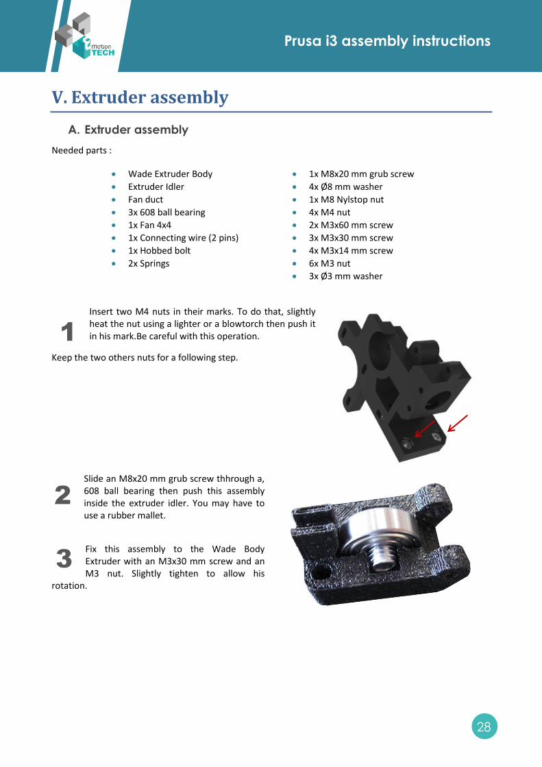
Insert two M4 nuts in their marks. To do that, slightly heat the nut using a lighter or a blowtorch then push it in his mark.Be careful with this operation.
Keep the two others nuts for a following step.
Slide an M8x20 mm grub screw thhrough a, 608 ball bearing then push this assembly inside the extruder idler. You may have to use a rubber mallet.
Fix this assembly to the Wade Body Extruder with an M3x30 mm screw and an M3 nut. Slightly tighten to allow his
rotation.
1
3
2
3
3
3
Prusa i3 assembly instructions
29
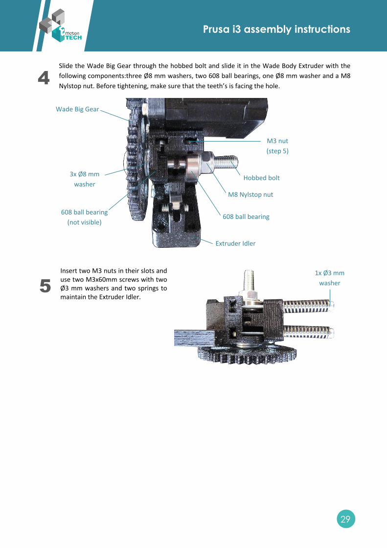
Slide the Wade Big Gear through the hobbed bolt and slide it in the Wade Body Extruder with the
following components:three Ø8 mm washers, two 608 ball bearings, one Ø8 mm washer and a M8
Nylstop nut. Before tightening, make sure that the teeth’s is facing the hole.
Insert two M3 nuts in their slots and use two M3x60mm screws with two Ø3 mm washers and two springs to maintain the Extruder Idler.
4
3
5
3
Wade Big Gear
Hobbed bolt
Extruder Idler
3x Ø8 mm
washer
608 ball bearing
(not visible) 608 ball bearing
M8 Nylstop nut
M3 nut
(step 5)
1x Ø3 mm
washer
Prusa i3 assembly instructions
30
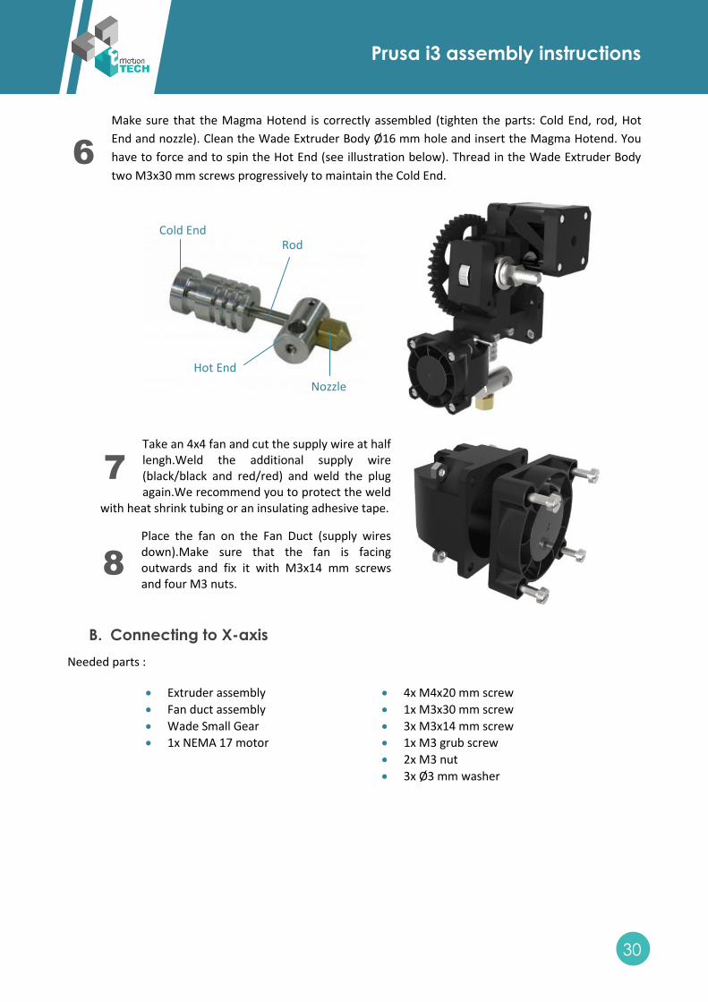
Make sure that the Magma Hotend is correctly assembled (tighten the parts: Cold End, rod, Hot
End and nozzle). Clean the Wade Extruder Body Ø16 mm hole and insert the Magma Hotend. You
have to force and to spin the Hot End (see illustration below). Thread in the Wade Extruder Body
two M3x30 mm screws progressively to maintain the Cold End.
Take an 4x4 fan and cut the supply wire at half lengh.Weld the additional supply wire (black/black and red/red) and weld the plug again.We recommend you to protect the weld
with heat shrink tubing or an insulating adhesive tape.
Place the fan on the Fan Duct (supply wires down).Make sure that the fan is facing outwards and fix it with M3x14 mm screws and four M3 nuts.
B. Connecting to X-axis
Needed parts :
Extruder assembly
Fan duct assembly
Wade Small Gear
1x NEMA 17 motor
4x M4x20 mm screw
1x M3x30 mm screw
3x M3x14 mm screw
1x M3 grub screw
2x M3 nut
3x Ø3 mm washer
Cold End Rod
Hot End
Nozzle
6
3
7
3 8
3
Prusa i3 assembly instructions
31
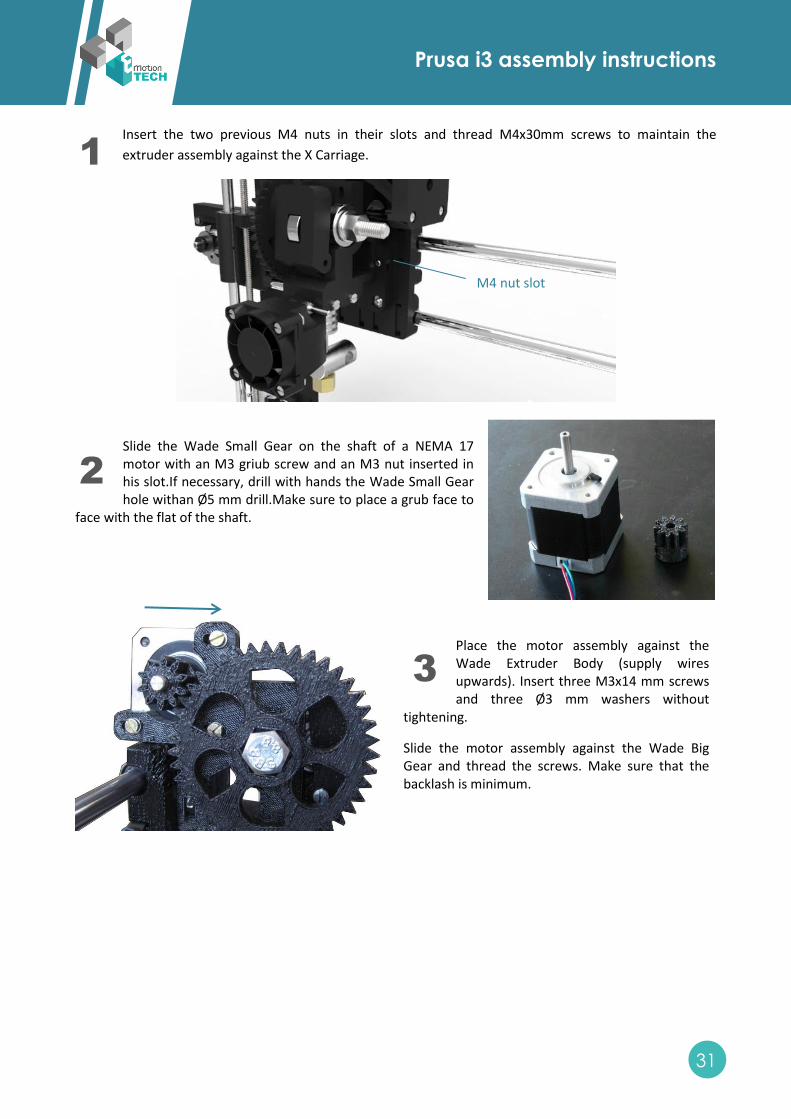
Insert the two previous M4 nuts in their slots and thread M4x30mm screws to maintain the
extruder assembly against the X Carriage.
Slide the Wade Small Gear on the shaft of a NEMA 17 motor with an M3 griub screw and an M3 nut inserted in his slot.If necessary, drill with hands the Wade Small Gear hole withan Ø5 mm drill.Make sure to place a grub face to
face with the flat of the shaft.
Place the motor assembly against the Wade Extruder Body (supply wires upwards). Insert three M3x14 mm screws and three Ø3 mm washers without
tightening.
Slide the motor assembly against the Wade Big Gear and thread the screws. Make sure that the backlash is minimum.
1
3
2
3
3
3
M4 nut slot
Prusa i3 assembly instructions
32
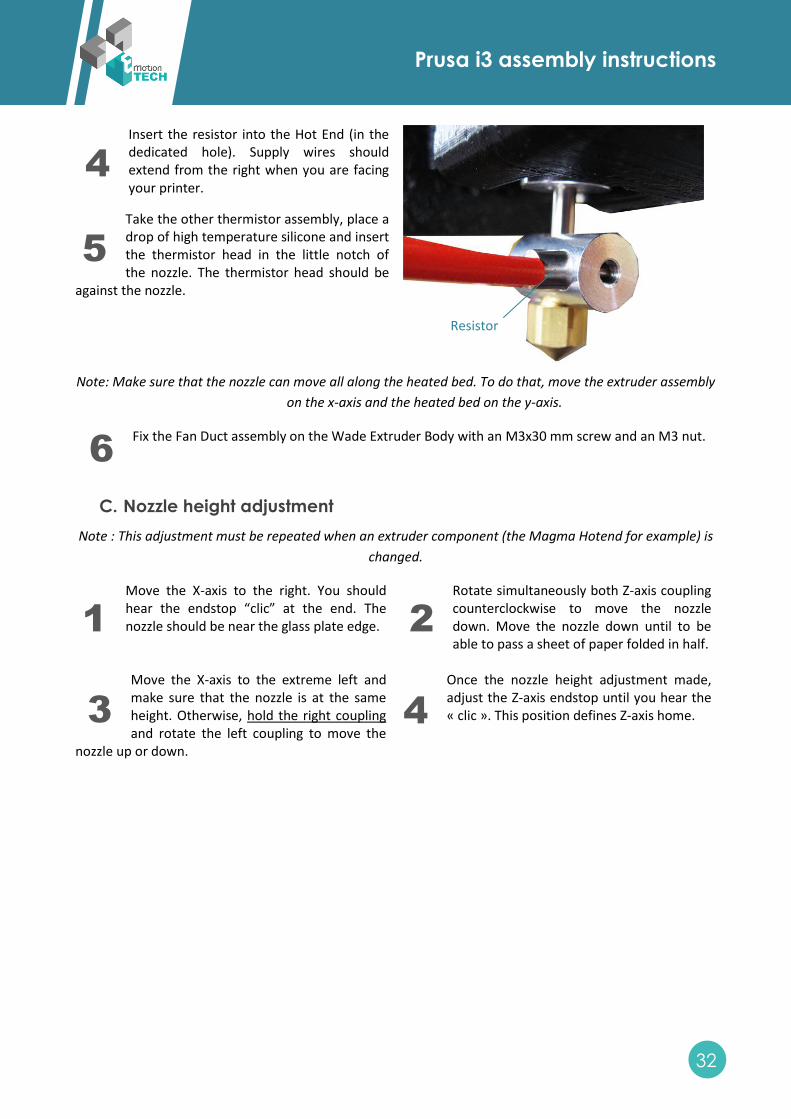
Insert the resistor into the Hot End (in the dedicated hole). Supply wires should extend from the right when you are facing your printer.
Take the other thermistor assembly, place a drop of high temperature silicone and insert the thermistor head in the little notch of the nozzle. The thermistor head should be
against the nozzle.
Note: Make sure that the nozzle can move all along the heated bed. To do that, move the extruder assembly
on the x-axis and the heated bed on the y-axis.
Fix the Fan Duct assembly on the Wade Extruder Body with an M3x30 mm screw and an M3 nut.
C. Nozzle height adjustment
Note : This adjustment must be repeated when an extruder component (the Magma Hotend for example) is
changed.
Move the X-axis to the right. You should hear the endstop “clic” at the end. The nozzle should be near the glass plate edge.
Rotate simultaneously both Z-axis coupling counterclockwise to move the nozzle down. Move the nozzle down until to be able to pass a sheet of paper folded in half.
Move the X-axis to the extreme left and make sure that the nozzle is at the same height. Otherwise, hold the right coupling and rotate the left coupling to move the
nozzle up or down.
Once the nozzle height adjustment made, adjust the Z-axis endstop until you hear the « clic ». This position defines Z-axis home.
4
3
5
3
Resistor
1
3
2
3
3
3
4
3
6
3
Prusa i3 assembly instructions
33
VI. Electronics and wiring
A. Mounting electronics
Needed parts :
RAMPS
Atmega 2650
4x stepsticks
3x Arduino washer
3x M3x30 mm screw
3x M3 nut
3x Ø3 mm washer
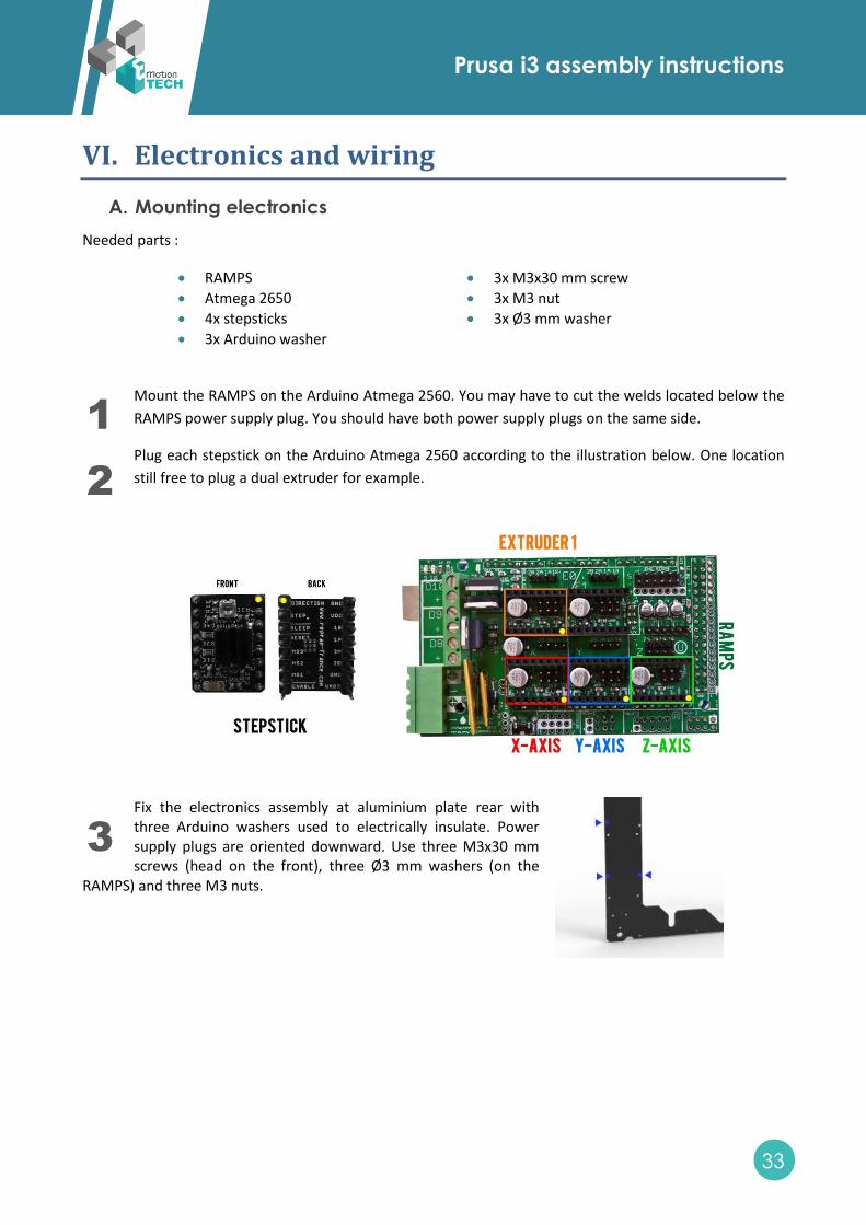
Mount the RAMPS on the Arduino Atmega 2560. You may have to cut the welds located below the
RAMPS power supply plug. You should have both power supply plugs on the same side.
Plug each stepstick on the Arduino Atmega 2560 according to the illustration below. One location
still free to plug a dual extruder for example.
Fix the electronics assembly at aluminium plate rear with three Arduino washers used to electrically insulate. Power supply plugs are oriented downward. Use three M3x30 mm screws (head on the front), three Ø3 mm washers (on the
RAMPS) and three M3 nuts.
1
3
2
3
3
3
Prusa i3 assembly instructions
34
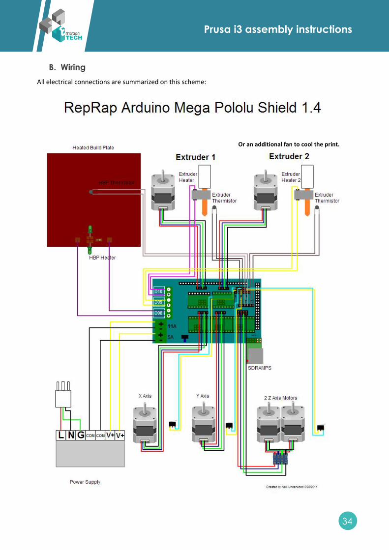
B. Wiring
All electrical connections are summarized on this scheme:
Or an additional fan to cool the print.
Prusa i3 assembly instructions
35
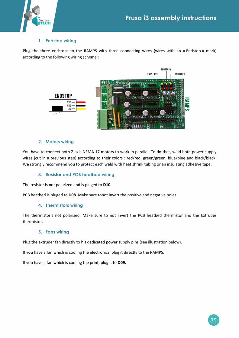
1. Endstop wiring
Plug the three endstops to the RAMPS with three connecting wires (wires with an « Endstop » mark)
according to the following wiring scheme :
2. Motors wiring
You have to connect both Z-axis NEMA 17 motors to work in parallel. To do that, weld both power supply
wires (cut in a previous step) according to their colors : red/red, green/green, blue/blue and black/black.
We strongly recommend you to protect each weld with heat shrink tubing or an insulating adhesive tape.
3. Resistor and PCB heatbed wiring
The resistor is not polarized and is pluged to D10.
PCB heatbed is pluged to D08. Make sure tonot invert the positive and negative poles.
4. Thermistors wiring
The thermistoris not polarized. Make sure to not invert the PCB heatbed thermistor and the Extruder
thermistor.
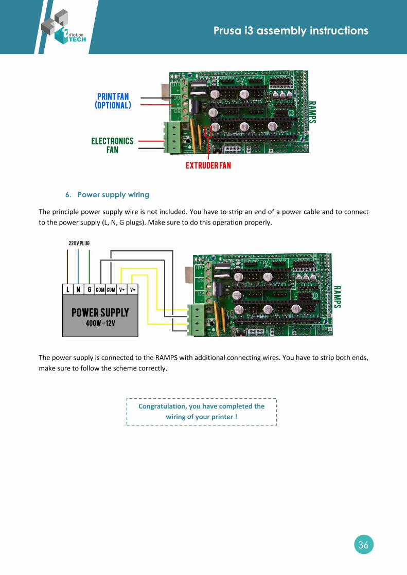
5. Fans wiring
Plug the extruder fan directly to his dedicated power supply pins (see illustration below).
If you have a fan which is cooling the electronics, plug it directly to the RAMPS.
If you have a fan which is cooling the print, plug it to D09.
Prusa i3 assembly instructions
36
6. Power supply wiring
The principle power supply wire is not included. You have to strip an end of a power cable and to connect
to the power supply (L, N, G plugs). Make sure to do this operation properly.
The power supply is connected to the RAMPS with additional connecting wires. You have to strip both ends,
make sure to follow the scheme correctly.
Congratulation, you have completed the
wiring of your printer !