aluminium prusa i3
DESCRIPTION
Aluminium Prusa i3 Assemble InstructionTRANSCRIPT

Assembly Instructions of Geeetech Aluminium Prusa I3

Shenzhen GETECH CO.,LTD
GEEETECH
2
CONTENT
Assembly Instructions of Geeetech Aluminium Prusa I3 ............................................................ 1
CONTENT ........................................................................................................................................ 2
Safety Instructions ............................................................................................................................ 3
Preparation ........................................................................................................................................ 4
1. Unfold the box and check the package.......................................................................................... 5
2. Assemble Y axis ............................................................................................................................ 5
2.1Assemble the 2 threaded rods. ............................................................................................. 5
2.2Attach the front and rear side support plates of the rods. ..................................................... 6
2.3Assemble the Y idler ............................................................................................................ 7
2.4. Mount the Y motor ............................................................................................................. 9 3. Build the printing platform ......................................................................................................... 10
4. Assemble Y smooth rods ............................................................................................................. 11
5. Mount the Y-axis belt .................................................................................................................. 11
6. Assemble the Z-axis stepper motor, bottom mount and couplings.............................................. 12
7. Assemble Y - Z axis .................................................................................................................... 13
8. Assemble the X axis (the horizontal axis) ................................................................................... 14
8.1 Assemble the X-Axis left end ........................................................................................... 14
8.2 Assemble the X-Axis right end ......................................................................................... 16
8.3 Assemble the extruder carriage. ........................................................................................ 16 9. Assemble the X-axis and Z-axis together .................................................................................... 18
10. Assemble the X belt driving wheel ........................................................................................... 20
11. Mount the LCD panel ................................................................................................................ 22
12. Mount the fan ............................................................................................................................ 23
13. Mount the board on the left side panel of the printer ................................................................ 24
14. Attach he heated bed. ................................................................................................................ 25
15. Mount the endstops of Y and Z axis .......................................................................................... 26
16. Wiring ....................................................................................................................................... 27
17. Arrange the wires and tidy them up with the coil. .................................................................... 28

Shenzhen GETECH CO.,LTD
GEEETECH
3
Safety Instructions
Building the printer will require a certain amount of physical dexterity, common
sense and a thorough understanding of what you are doing. We have provided this
detailed instruction to help you assemble it easily.
However ultimately we cannot be responsible for your health and safety whilst
building or operating the printer, with that in mind be sure you are confident with
what you are doing prior to commencing with building or buying. Read the entire
manual to enable you to make an informed decision.
Building and operating involves electricity, so all necessary precautions should
be taken and adhered to, the printer runs on 12V supplied by a certified power supply,
so you shouldn’t ever have to get involved with anything over 12V but bear in mind
there can still be high currents involved and even at 12V they shouldn’t be taken
lightly.
High temperatures are involved with 3D Printing, the Extrusion nozzle of the hot
end can run about 230°C, the heated bed runs 110°C and the molten plastic extruded
will initially be at around 200°C, so special care and attention should be made when
handling these parts of the printer during operation.
We wouldn’t recommend leaving your printer running unattended, or at least
until you are confident to do so. We cannot be held responsible for any loss, damage,
threat, hurt or other negligent result from either building or using the printer.

Shenzhen GETECH CO.,LTD
GEEETECH
4
Preparation
1. Unpack the kit and check if all parts are in the box and check the condition of each
part, there might be some damage during shipping. To help you with this, there is
BOM in the box and each bag was labeled with part number.
2. Contact our customer service immediately by email or through the website if you
find any missing or damaged parts. And on the bottom of the BOM, there is a
signature of reviewer, please take a picture of it and attach the picture in your mail.
3. Read through each chapter of these instructions to gain an over-all idea of what is
involved and how long it might take, before starting on the work described.
4. Before you start, you can put all the part in order to save your time especially those
screws and nuts. Do not mix them up.
5. Ensure you have the necessary skills to carry out the work, or enlist the help of
someone who does.
6. Work on a big firm table or bench in a clean dry well-lit area.
7. This kit contains tiny parts; please keep them away from kids under 3.
8. Ask for help if you run into any problems - our contact details are on the website
and we will always do our best to resolve any problems encountered.

Shenzhen GETECH CO.,LTD
GEEETECH
5
1. Unfold the box and check the package
Unfold the package and take all the parts out to check the condition of the items. As
you can see, all the parts are packed very carefully.
Tips:
1. Before assembly, you are advised to put all the parts, especially the screws and nuts
in order, which will save you a lot of time looking for the required parts.
2. The part ID is corresponding to the number labeled on the bag of every part.Some
parts may not have label, you can refer to the pictures on the package list.
2. Assemble Y axis
2.1Assemble the 2 threaded rods.
Video
Pic Part ID Required
number
Required parts
NO.5 2 Y threaded rod
NO.A12 2 connecting plate
NO.10 6 Spring washer
NO.9 8 M10 washer
NO.13 8 M10 nut
Thread the nuts and washers into the two M10 threaded rods separately. The orders
should be:
1) Thread theY plate connecting plate in the middle.

Shenzhen GETECH CO.,LTD
GEEETECH
6
2) Thread the M10 washer > spring washer >M10 nut > M10 nut > M10 washer on
the left
3) Thread theM10 washer < spring washer < M10 nut < M10 nut< spring washer <
M10 washer on the right
2.2Attach the front and rear side support plates of the rods.
Video
Pic Part ID Required
number
Required parts
NO. A2
1
Front Side Support
NO.A3
1
Rear Side Support

Shenzhen GETECH CO.,LTD
GEEETECH
7
Slide assembled threaded rods into the side support plates. Screw up the rods and
plates with 4 M10 nuts and M10 washers.
* Tips:the Y-axis must be a rectangle, that is the rods on both side should be parallel,
so is the front and rear plate. Otherwise it will cause obstruction for the belt later.
2.3Assemble the Y idler
Video
Pic Part ID Required
number
Required parts
NO.34
2
624ZZ Ball
bearing
NO.38
1
bearing holder
NO.28
1
M4 x25 screw
NO.12
1
M4 lock nut
NO.A10
1
Guide Block
A
NO.12
4
M10 washer
NO.13
4
M10 nut

Shenzhen GETECH CO.,LTD
GEEETECH
8
NO.A11 1 Guide Block
B
NO.22 3 M3 x 25screw
NO.28 1 M4x25 screw
NO.15
1
M3 wing nut
NO.7 3 M3 washer
NO.11 2 M3 nut
NO.8 2 M4 washer
NO.12
1
M4 nut
Step1. Amount guide block A and B onto the front support plate together, screw up it
with 2 M3x25 screws, M3washers and M3 nuts.
Note: the guide block B is close to front support plate.
Step2. Thread a M3 x25screw and M3washer through the bearing holder.
Step3. Put a M4 x25screw and M4wsaher through the holes with the two 624ZZ
bearings in between. Lock the other end with a M4 lock nut. You may need a spanner
to tighten locknut.
Step4. Mount the assembled bearing holder through the guide blocks onto the front
support plates. And screw it with a wing nut.
*Please leave enough room for the belt between the ball bearing and the screw.

Shenzhen GETECH CO.,LTD
GEEETECH
9
2.4. Mount the Y motor
Video
Pic Part ID Required number Required parts
NO. A9
1
Y motor fixed plate
NO.57
1
Stepper motor
NO.36
1
pulley
NO.19 3 M3 x 10screw
NO.20 2 M3x16screw
NO.7 5 M3 washer
Step1. Mount the pulley on the motor shaft, one of the screws should be screwed on
the cross section of the shaft. Screw it up tightly.
Step2. Insert the motor block into the slot; you may need to use a little strength to do
this. Then screw the motor on the Y motor fix plate with 3 M3 x 10 screws and
M3washers

Shenzhen GETECH CO.,LTD
GEEETECH
10
Step3. Fix the block plate with 2 M3 x 16 screws and M3 washers.
3. Build the printing platform
Video
Pic Part ID Required
number
Required parts
NO.A5
1
Y building
platform
NO.39
1
Y belt mount
NO.32
4
SCS8UU linear
bearing
NO. 43
4
Zip tie
NO.19 2 M3 x 10 screw
NO.26 16 M4x12 screw
Shenzhen GETECH CO.,LTD
GEEETECH
11
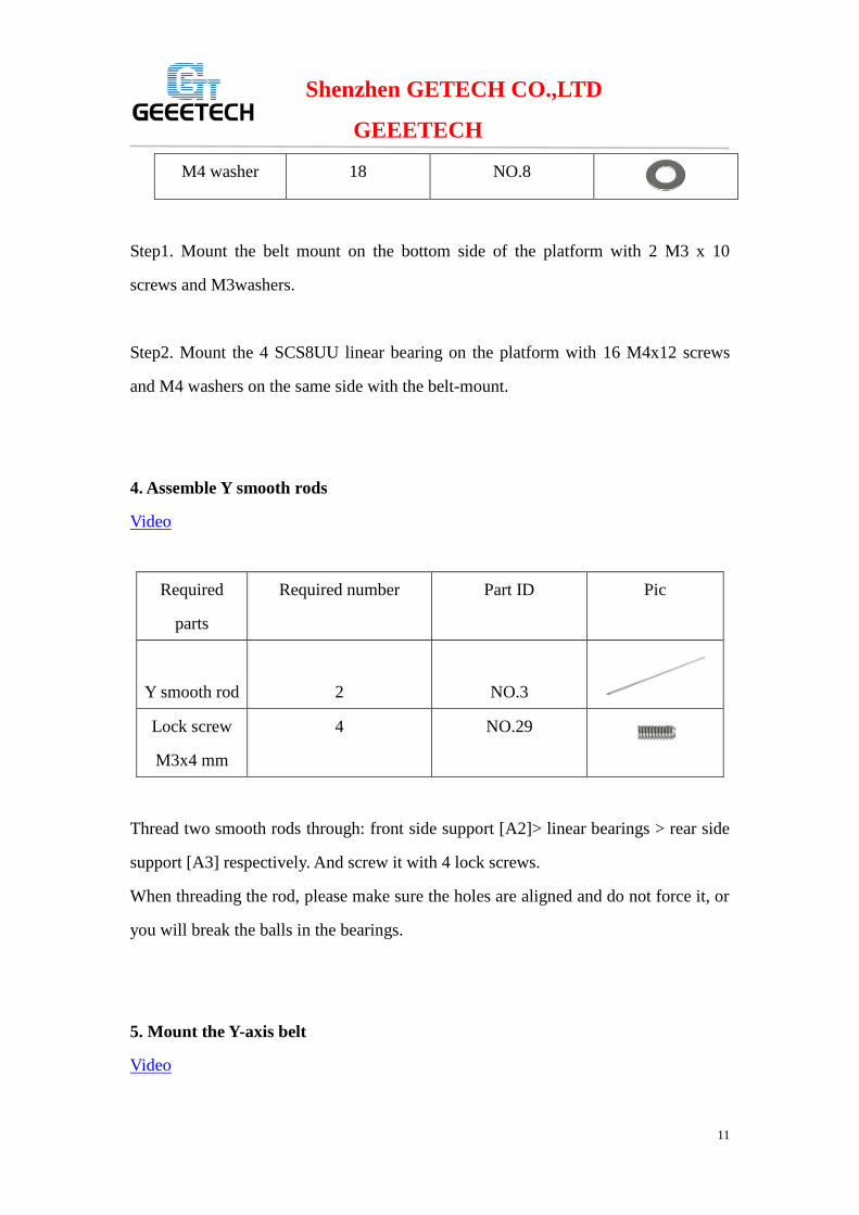
NO.8 18 M4 washer
Step1. Mount the belt mount on the bottom side of the platform with 2 M3 x 10
screws and M3washers.
Step2. Mount the 4 SCS8UU linear bearing on the platform with 16 M4x12 screws
and M4 washers on the same side with the belt-mount.
4. Assemble Y smooth rods
Video
Pic Part ID Required number Required
parts
NO.3
2
Y smooth rod
NO.29 4 Lock screw
M3x4 mm
Thread two smooth rods through: front side support [A2]> linear bearings > rear side
support [A3] respectively. And screw it with 4 lock screws.
When threading the rod, please make sure the holes are aligned and do not force it, or
you will break the balls in the bearings.
5. Mount the Y-axis belt
Video
Shenzhen GETECH CO.,LTD
GEEETECH
12
Pic Part ID Required number Required parts
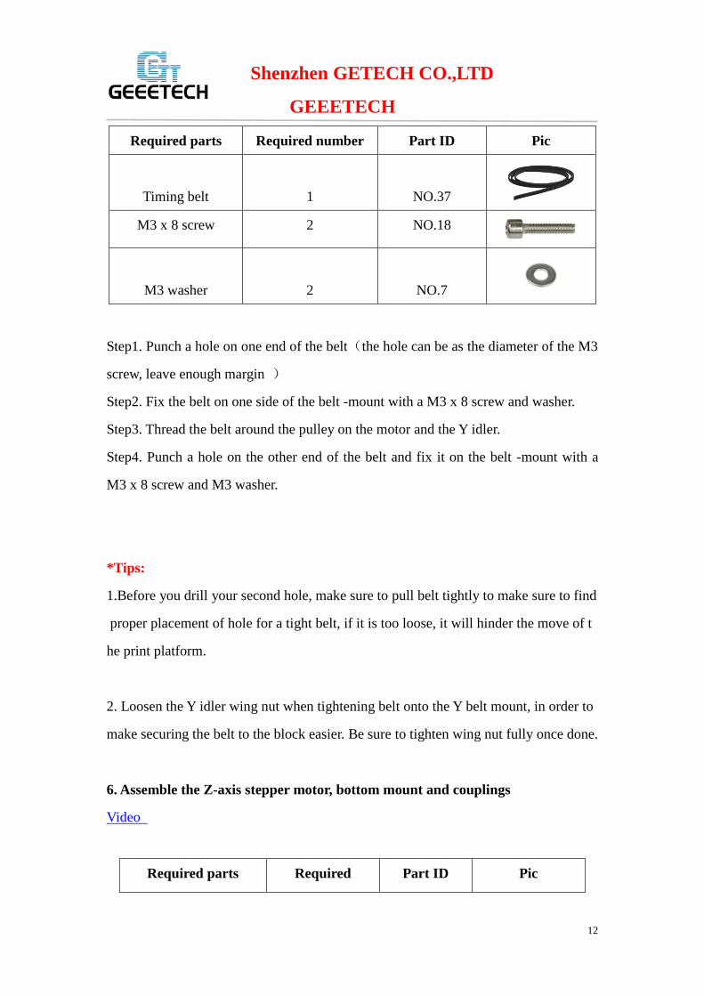
NO.37
1
Timing belt
NO.18 2 M3 x 8 screw
NO.7
2
M3 washer
Step1. Punch a hole on one end of the belt(the hole can be as the diameter of the M3
screw, leave enough margin )
Step2. Fix the belt on one side of the belt -mount with a M3 x 8 screw and washer.
Step3. Thread the belt around the pulley on the motor and the Y idler.
Step4. Punch a hole on the other end of the belt and fix it on the belt -mount with a
M3 x 8 screw and M3 washer.
*Tips:
1.Before you drill your second hole, make sure to pull belt tightly to make sure to find
proper placement of hole for a tight belt, if it is too loose, it will hinder the move of t
he print platform.
2. Loosen the Y idler wing nut when tightening belt onto the Y belt mount, in order to
make securing the belt to the block easier. Be sure to tighten wing nut fully once done.
6. Assemble the Z-axis stepper motor, bottom mount and couplings
Video
Pic Part ID Required Required parts

Shenzhen GETECH CO.,LTD
GEEETECH
13
number
NO.A1
1
X-Z frame
NO. A6
2
Z Motor fixed plate
NO.57
2
Stepper Motor
NO.35
2
Coupling
NO.20 4 M3 x 16screw
NO.19 8 M3x10 screw
NO.7
12
M3 washer
Step1. It would be easier to mount the motor on plates first, screw it with 8
M3x10screws and M3 washers
Step2. Thread the wires of the motors through the hole. Mount the assembled motor to
the X-Z frame (A1), and screw the X-Z frame with 4 M3 x 16screws and M3washers.
Step3. Mount the coupling on the motor shaft, one of the screws should be screwed on
the cross section of the shaft. Screw the small screw tightly.
7. Assemble Y - Z axis

Shenzhen GETECH CO.,LTD
GEEETECH
14
Video
Pic Part ID Required
number
Required parts
NO.20 4 M3 x 16 screw
NO.7 4 M3 washer
Step1. Held upright the X-Z frame on the threaded rods (Right after the Y connecting
plate)
Step2. Screw up the main frame to the Y connecting plate with 4 M3 x16 screws and
M3 washers.
8. Assemble the X axis (the horizontal axis)
Video
8.1 Assemble the X-Axis left end
Pic Part ID Required number Required parts
NO.P1
1 X-axis left end
NO.16 1 Brass nut
NO. 20 4 M3 x 16 screw

Shenzhen GETECH CO.,LTD
GEEETECH
15
NO.57
1 Stepper motor
NO.36 1 Pulley
NO.19 3 M3 x 10screw
NO.45
1 End stop
NO.17 2 M2.5 X 16 screw
NO.25 1 M3 x50 screw
NO.7 7 M3wsaher
NO.6 2 M2.5 washer
Step1. Mount a brass nut under left end with 4 M3 x 16 screws and M3washers.
Step2.Mount end stop of X-axis.
1).Mount the X end stop on the top of X-axis left end, and screw it with 2M2.5x16
screws and M2.5 washers.
2). Fix the M3x 50 screw on left end. (This is for the Y end stop).
Step3. Mount the X-axis motor.
1) Mount the pulley on the motor shaft, one of the screws should be screwed on the
cross section of the shaft. Screw it tightly.
2)Mount stepper motor on the left end, and screw it with 3M3x10screws and
washers.
*Please pay attention to the mount direction of the pulley, which is opposite to that
of the Y-axis.

Shenzhen GETECH CO.,LTD
GEEETECH
16
8.2 Assemble the X-Axis right end
Pic Part ID Required number Required parts
NO.P2
1 X-axis right end
NO. 20 4 M3 x 16 screw
NO.7 4 M3wsaher
NO.16 1 Brass nut
Step1.Mount a brass nut under the X-axis right end with 4 M3 x 16 screws and M3
washers.
8.3 Assemble the extruder carriage.
Video
Step1. Mount the X-axis belt bracket on the smooth rods.
Pic Part ID Required number Required parts

Shenzhen GETECH CO.,LTD
GEEETECH
17
NO.P4 1 belt bracket
NO.43 4 Zip tie
NO.33
2
LM8UU linear
bearing
1) Insert the linear bearings into the slot of the bracket.
2) Thread the zip-tie through the belt bracket. Tie them up with zip ties.
*The stretch-out part is towards the Left X-axis end.
Step2. Mount the extruder holder to the belt bracket.
Pic Part ID Required
number
Required parts
NO.P3
1
Extruder
holder
NO.26 2 M4 x
12screw
NO.12 2 M4 nut
NO.8 2 M4wsaher
1). Put the 2 M4 nut into the hole on the Extruder holder.
2). Screw up the belt bracket and the extruder holder with 2 M4 x 12 screws and
M4washers.

Shenzhen GETECH CO.,LTD
GEEETECH
18
*Note: In the video, the P3 is a 3D printed part, for better printing effect, we have
upgraded this part as a metal part, so there is a bit difference from the video. Detailed
information is in accordance with the final product.
Step3.Mount the extruder on the holder
Pic Part ID Required number Required
parts
NO.55
1
MK8
extruder
NO.27 2 M4 x 6
screw
NO.8 2 M4 washer
Mount the assembled extruder on the extruder holder. Use 2 M4 x 6 screws and
M4washers to fix it.
9. Assemble the X-axis and Z-axis together
Video
Step1. Assemble the X-axis
So far, we have finished the three main part of the X axis, now we can assemble them
together.
Pic Part ID Required number Required
parts
NO.2
2
X smooth
rod

Shenzhen GETECH CO.,LTD
GEEETECH
19
NO.30 2 Screw
Lock ring
Thread the left end>extruder part >the screwing >right end onto the smooth rods in
turn.
Step1. Assemble the Z-axis
Pic Part ID Required
number
Required parts
NO.4 2 Z threaded rod
NO.1 2 Z smooth rod
NO.29 2 M3x4 mm
Lock screw
NO.A7 1 Z Top Support
plate
NO. 20 4 M3 x 16 screw
NO.7 4 M3wsaher
1) .Thread two threaded rods through two the brass nuts, keep both end aligned.
2). Connect the bottom end of the threaded rods to the couplings respectively. If the
distance between the two threaded rods is different from that of the two couplings,
you need to adjust one end of the X axis to make sure the threaded rods are vertical.
3). Thread the smooth rods into the bearings on the two ends. Be gentle, please.
4). Mount the two Z top support plates to the X-Z frame. Screw up it with 4 M3x16
screws and M3 washers.
5). screw up the couplings very tightly
Shenzhen GETECH CO.,LTD
GEEETECH
20
6). fix the locking rings on the X axis smooth rod.
7). screw up the Z smooth rod at the bottom with 2 M3x4Lock screws.
10. Assemble the X belt driving wheel
Video
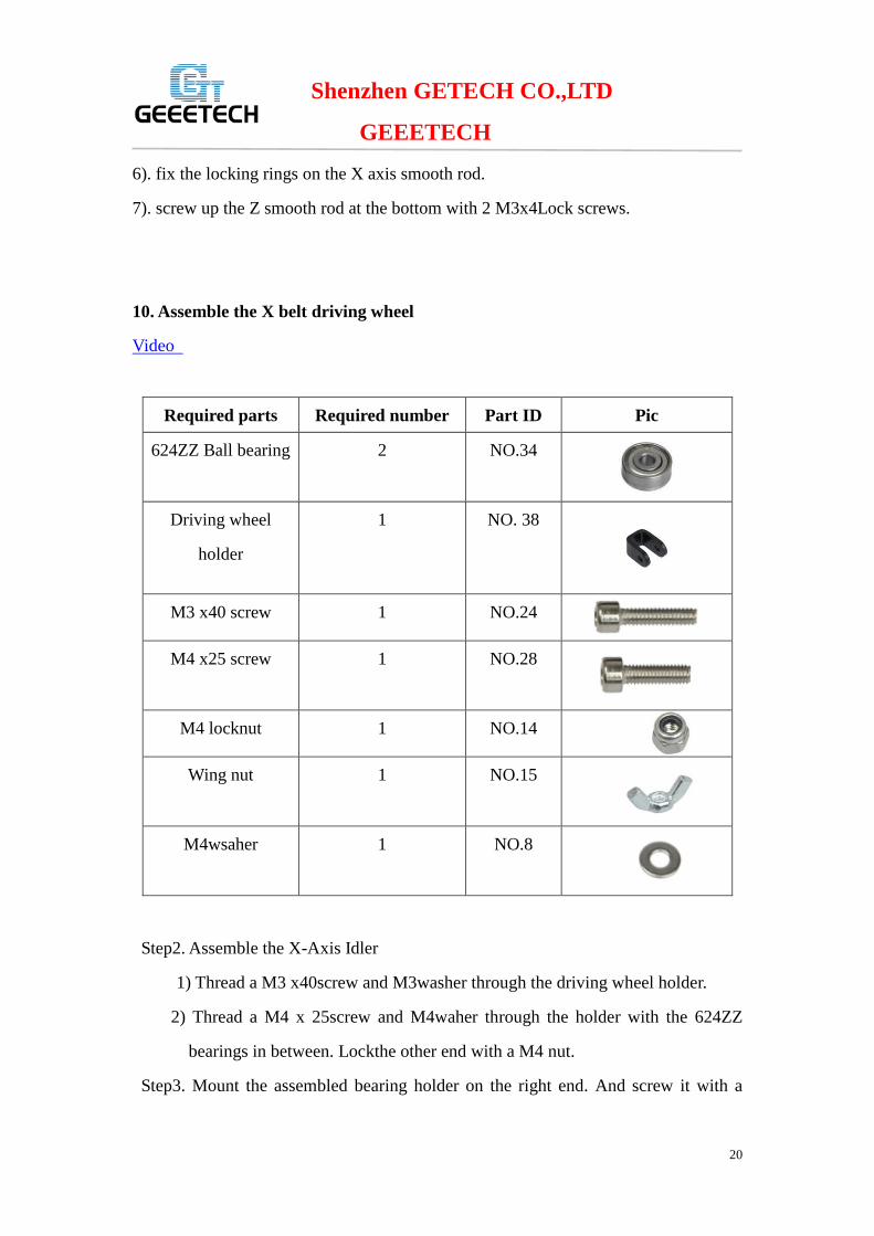
Pic Part ID Required number Required parts
NO.34 2 624ZZ Ball bearing
NO. 38 1 Driving wheel
holder
NO.24 1 M3 x40 screw
NO.28 1 M4 x25 screw
NO.14 1 M4 locknut
NO.15 1 Wing nut
NO.8 1 M4wsaher
Step2. Assemble the X-Axis Idler
1) Thread a M3 x40screw and M3washer through the driving wheel holder.
2) Thread a M4 x 25screw and M4waher through the holder with the 624ZZ
bearings in between. Lockthe other end with a M4 nut.
Step3. Mount the assembled bearing holder on the right end. And screw it with a

Shenzhen GETECH CO.,LTD
GEEETECH
21
wing nut.
11. Mount the X-axis belt.
Pic Part ID Required
number
Required parts
NO.37
1
Timing Belt
NO.43
2
Zip tie
Step1. Thread the belt around pulley on the motor end.
Step2. Insert one end of the belt in the slot. Tie it up with a zip tie.
Step2. Another end of the belt should be threaded through the belt driving wheel on
the right end of the X-axis.
Step3. Insert another end of the belt into the slot. You may need to use the tweezers to
help you insert the belt.
*Pay attention to the tooth mesh of the belt and that on the bracket. Tie up both ends
tightly.
* Do not rush to cut the belt until you are sure of the belt length.

Shenzhen GETECH CO.,LTD
GEEETECH
22
11. Mount the LCD panel
Video
Pic Part ID Required
number
Required parts
NO.58
1
LCD 2004
NO.40
4 Spacer
NO.59
1 knob
NO.7
4 M3washer
NO.21 4 M3 x 20 screw
NO.7 4 M3 nut
Mount the LCD into the top of main frame from back to front; screw it up with
4M3x16 screws, M3 washers and M3 nuts.
*Note: Four spacers should between LCD and frame.

Shenzhen GETECH CO.,LTD
GEEETECH
23
12. Mount the fan
Video
Pic Part ID Required number Required parts
NO.49
1
Fan
NO.22 2 M3 x 25screw
NO.A4
1
Fan mount
NO.7 4 M3washer
NO.20 2 M3 x 16screw
Fix the fan on the fan mount with 2 M3 x 25 screws and M3washers. Mount the fixed
block on the main frame with 2 M3x16 screws and M3 washers.
*Mind the direction of the wires.

Shenzhen GETECH CO.,LTD
GEEETECH
24
13. Mount the board on the left side panel of the printer
Video
Pic Part ID Required number Required parts
NO.56
1
Control board
NO.21
4
M3 x 20screw
NO.40 4 Spacer
NO.7 4 M3washer
NO.11 4 M3 nut
Mount control board onto the back of X-Z frame, and screw up it with M3x20screws,
M3washers and M3 nuts.
*Attention:
The four A4988 stepper motor driver board is plugged on the board before shipping.
The four spacers should between X-Z frame and control board.

Shenzhen GETECH CO.,LTD
GEEETECH
25
14. Attach he heated bed.
Video
Pic Part ID Required
number
Required parts
NO.48
1
Heat bed
NO.44
1
Borosilicate glass
NO.47
2
Heating wire
NO.46
2
Thermometry wire
NO.31
4
Spring
NO.7 4 M3 washer
NO.23 4 M3 x30 screw
NO.41
4
clamp
Mount the heat bed on the platform with 4 M3 x30 screws and wing nuts with springs
in between. Clamp the heat bed and the glass sheet.
*Note
The heating wire is pre-soldered on the bed and the thermometry wire is attached on
the bed.
The soldered side is better to be attached downwards.
Shenzhen GETECH CO.,LTD
GEEETECH
26
15. Mount the endstops of Y and Z axis
Video
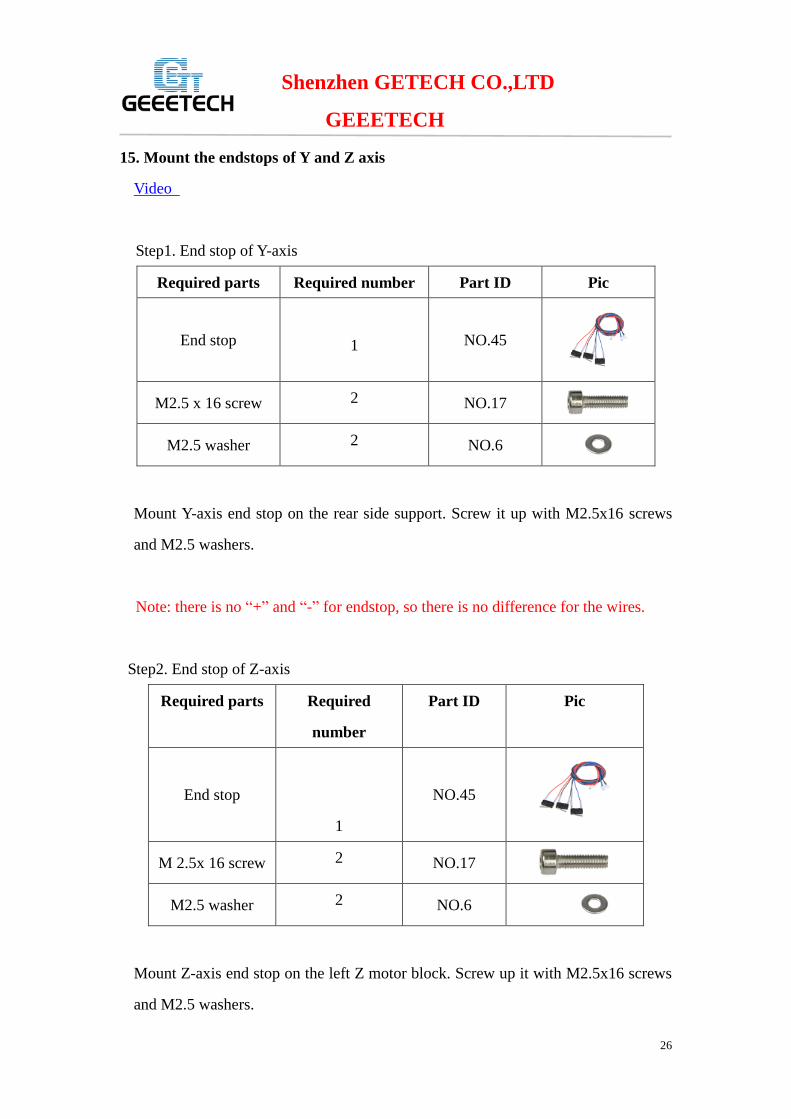
Step1. End stop of Y-axis
Pic Part ID Required number Required parts
NO.45
1 End stop
NO.17 2 M2.5 x 16 screw
NO.6 2 M2.5 washer
Mount Y-axis end stop on the rear side support. Screw it up with M2.5x16 screws
and M2.5 washers.
Note: there is no “+” and “-” for endstop, so there is no difference for the wires.
Step2. End stop of Z-axis
Pic Part ID Required
number
Required parts
NO.45
1
End stop
NO.17 2 M 2.5x 16 screw
NO.6 2 M2.5 washer
Mount Z-axis end stop on the left Z motor block. Screw up it with M2.5x16 screws
and M2.5 washers.

Shenzhen GETECH CO.,LTD
GEEETECH
27
16. Wiring
Please refer to the picture
Note: there are two stepper motors for Z axis, the connecter is as shown in the
following picture:

Shenzhen GETECH CO.,LTD
GEEETECH
28
For detailed wiring instruction, please refer to the video.
17. Arrange the wires and tidy them up with the coil.
The whole printer assembly work is already done.
Hope you enjoy the whole process.