inl sec-00219 reactor prioritization for evaluation … sec-00219 reactor prioritization for...
TRANSCRIPT
Draft
ADVISORY BOARD ON RADIATION AND WORKER HEALTH
National Institute for Occupational Safety and Health
INL SEC-00219 REACTOR PRIORITIZATION FOR EVALUATION OF ORAUT-OTIB-0054 APPLICABILITY
Contract No. 211-2014-58081 SCA-TR-2016-SEC002, Revision 1
Prepared by
Stephen L. Ostrow, PhD
SC&A, Inc. 1608 Spring Hill Road, Suite 400
Vienna, Virginia 22182
Saliant, Inc. 5579 Catholic Church Road Jefferson, Maryland 21755
June 2016
DISCLAIMER
This is a working document provided by the Centers for Disease Control and Prevention (CDC) technical support contractor, SC&A for use in discussions with the National Institute for Occupational Safety and Health (NIOSH) and the Advisory Board on Radiation and Worker Health (ABRWH), including its Working Groups or Subcommittees. Documents produced by SC&A, such as memorandum, white paper, draft or working documents are not final NIOSH or ABRWH products or positions, unless specifically marked as such. This document prepared by SC&A represents its preliminary evaluation on technical issues.
NOTICE: This report has been reviewed to identify and redact any information that is protected by the Privacy Act 5 U.S.C. § 552a and has been cleared for distribution.

Effective Date: June 10, 2016
Revision No. 1 (Draft)
Document No./Description: SCA-TR-2016-SEC002
Page No. 2 of 44
NOTICE: This report has been reviewed to identify and redact any information that is protected by the Privacy Act 5 USC §552a and has been cleared for distribution.
SC&A, INC.: Technical Support for the Advisory Board on Radiation & Worker Health Review of NIOSH Dose Reconstruction Program
DOCUMENT TITLE: INL SEC-00219 Reactor Prioritization for Evaluation of ORAUT-OTIB-0054 Applicability
DOCUMENT NUMBER/ DESCRIPTION: SCA-TR-2016-SEC002
REVISION NO.: 1 (Draft) SUPERSEDES: 0 EFFECTIVE DATE: June 10, 2016 TASK MANAGER: John Stiver, MS, CHP [signature on file] PROJECT MANAGER: John Stiver, MS, CHP [signature on file] DOCUMENT REVIEWER(S):
John Stiver, MS, CHP [signature on file] John Mauro, PhD, CHP [signature on file]
Record of Revisions
Revision Number Effective Date Description of Revision
0 (Draft) 03/02/2016 Initial issue 1 06/10/2016 1.0 – summarized comments received on Rev. 0; 3.0 – added
Table 3 for convenience in locating reactors in Attachment 1; 3.0 – revised Table 5 to reflect changed prioritization of Attachment 1 and grouped some of the reactors together for joint evaluations; 4.0 – added references and SRDB numbers where available; Attachment 1 – expanded summary descriptions and reclassified some priority rankings; General – editorial revisions throughout the document.
Effective Date: June 10, 2016
Revision No. 1 (Draft)
Document No./Description: SCA-TR-2016-SEC002
Page No. 3 of 44
NOTICE: This report has been reviewed to identify and redact any information that is protected by the Privacy Act 5 USC §552a and has been cleared for distribution.
TABLE OF CONTENTS
Abbreviations and Acronyms.......................................................................................................... 4
1.0 Introduction ............................................................................................................................... 8
2.0 ORAUT-OTIB-0054 ............................................................................................................... 11
3.0 Evaluation ............................................................................................................................... 13
4.0 References ............................................................................................................................... 17
Attachment 1. INL Reactor Prioritization with Respect to ORAUT-OTIB-0054 Applicability Investigation.................................................................................................................................. 19

Effective Date: June 10, 2016
Revision No. 1 (Draft)
Document No./Description: SCA-TR-2016-SEC002
Page No. 4 of 44
NOTICE: This report has been reviewed to identify and redact any information that is protected by the Privacy Act 5 USC §552a and has been cleared for distribution.
ABBREVIATIONS AND ACRONYMS
Advisory Board Advisory Board on Radiation and Worker Health AEC Atomic Energy Commission
AFSR Argonne Fast Source Reactor AGCRSP Army Gas-Cooled Reactor Systems Program Al aluminum
ALPR Argonne Low Power Reactor ANP Aircraft Nuclear Propulsion
ANL-W Argonne National Laboratory-West ARA Auxiliary Reactor Area ARMF Advanced Reactivity Measurement Facility Number
ATR Advanced Test Reactor ATRC Advanced Test Reactor Critical Facility
Be beryllium BORAX Boiling Water Reactor Experiment BWR Boiling Water Reactor
Ci curie CET Critical Experiment Tank
CFA Central Facilities Area CFRMF Coupled Fast Reactivity Measurement Facility CRCE Cavity Reactor Critical Experiment
Cs cesium D2O deuterium oxide (“heavy” water)
DOE (U.S.) Department of Energy EBOR Experimental Beryllium Oxide Reactor EBR Experimental Breeder Reactor
EEOICPA Energy Employees Occupational Illness Compensation Program Act of 2000 EOCR Experimental Organic Cooled Reactor
ER Evaluation Report ESF engineered safety feature
Effective Date: June 10, 2016
Revision No. 1 (Draft)
Document No./Description: SCA-TR-2016-SEC002
Page No. 5 of 44
NOTICE: This report has been reviewed to identify and redact any information that is protected by the Privacy Act 5 USC §552a and has been cleared for distribution.
ETR Engineering Test Reactor
ETRC Engineering Test Reactor Critical Facility F Fahrenheit
FFTF Fast Flux Test Facility FRAN Nuclear Effects Reactor ft feet, foot
gpm gallons per minute GCRE Gas Cooled Reactor Experiment
GW gigawatt GWth gigawatt thermal H2O (“light”) water
HOTCE Hot Critical Experiment Hr hour
HTGR high-temperature gas-cooled reactor HTRE Heat Transfer Reactor Experiment Iodine iodine
IET Initial Engine Test IETF Initial Engine Test Facility
in inch INL Idaho National Laboratory kg kilogram
Kr krypton kWe kilowatt electric
kWth kilowatt thermal LOCA loss-of-coolant accident LOFT Loss of Fluid Test Facility
LPTF Low Power Test Facility LWR light water reactor
MAP mixed activation product MFP mixed fission product ML-1 Mobile Low-Power Reactor-1
Effective Date: June 10, 2016
Revision No. 1 (Draft)
Document No./Description: SCA-TR-2016-SEC002
Page No. 6 of 44
NOTICE: This report has been reviewed to identify and redact any information that is protected by the Privacy Act 5 USC §552a and has been cleared for distribution.
mrad millirad
MTHM metric ton heavy metal MTR Materials Test Reactor
MTU metric ton uranium MW megawatt MWd megawatt days
MWe megawatt electric MWth megawatt thermal
MW-hr megawatt-hour N2 nitrogen N/A not applicable
Na sodium NaK sodium-potassium (liquid metal)
NASA National Aeronautics and Space Administration NRAD Neutron Radiography Facility NRC (U.S.) Nuclear Regulatory Commission
NRF Naval Research Facility NIOSH National Institute for Occupational Safety and Health
OMRE Organic Moderated Reactor Experiment ORAU(T) Oak Ridge Associated Universities (Team) ORNL Oak Ridge National Laboratory
OTIB ORAUT Technical Information Bulletin PBF Power Burst Facility
Pu plutonium RMF Reactivity Measurement Facility RML Radiation Measurement Laboratory
SCRCE Spherical Cavity Reactor Critical Experiment SEC Special Exposure Cohort
SL-1 Stationary Low-Power Reactor SNAP Systems for Nuclear Auxiliary Power SNAPTRAN Systems for Nuclear Auxiliary Power Transient
Effective Date: June 10, 2016
Revision No. 1 (Draft)
Document No./Description: SCA-TR-2016-SEC002
Page No. 7 of 44
NOTICE: This report has been reviewed to identify and redact any information that is protected by the Privacy Act 5 USC §552a and has been cleared for distribution.
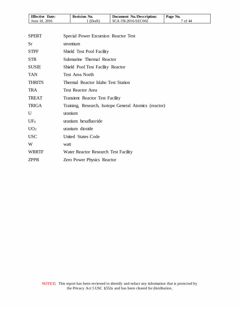
SPERT Special Power Excursion Reactor Test
Sr strontium STPF Shield Test Pool Facility
STR Submarine Thermal Reactor SUSIE Shield Pool Test Facility Reactor TAN Test Area North
THRITS Thermal Reactor Idaho Test Station TRA Test Reactor Area
TREAT Transient Reactor Test Facility TRIGA Training, Research, Isotope General Atomics (reactor) U uranium
UF6 uranium hexafluoride UO2 uranium dioxide
USC United States Code W watt WRRTF Water Reactor Research Test Facility
ZPPR Zero Power Physics Reactor

Effective Date: June 10, 2016
Revision No. 1 (Draft)
Document No./Description: SCA-TR-2016-SEC002
Page No. 8 of 44
NOTICE: This report has been reviewed to identify and redact any information that is protected by the Privacy Act 5 USC §552a and has been cleared for distribution.
1.0 INTRODUCTION
Following a series of meetings and discussions among the Advisory Board on Radiation and Worker Health (hereafter referred to as the “Advisory Board”), SC&A, and the National Institute for Occupational Safety and Health (NIOSH) and its technical contractor, Oak Ridge Associated Universities (ORAU), regarding NIOSH’s March 12, 2015, release of the Special Exposure Cohort (SEC) Petition SEC-00219 Evaluation Report for the Idaho National Laboratory (INL) (NIOSH 2015a),1 the Advisory Board requested that SC&A initially review two issues as part of a graded approach to assess the selected issues at this complex site: (1) class definition and (2) dose reconstructability and gap analysis. With respect to the latter, inherent in the SEC framework is the assumption that doses can be reconstructed with sufficient accuracy for site areas and time periods that lie outside the SEC class definition and that are not being held in reserve for further evaluation by NIOSH. Operations at INL involving radioactive materials were very complex, as many unique nuclear reactors and experiments were built and tested, irradiated nuclear fuel handled and processed, and radioactive waste disposed of. An SC&A report (SC&A 2015a) examined one aspect of the dose reconstructability assumption for several reactors in one of the several major site areas, the Test Reactor Area (TRA). Another SC&A report (SC&A 2015b) examined dose reconstructability for some of the reactors in another major site area, Test Area North (TAN).
1 Revision 1 of the ER was released on July 21, 2015 (NIOSH 2015b).
A primary tool that NIOSH uses for internal dose reconstruction is the guidance appearing in ORAUT-OTIB-0054, Fission and Activation Product Assignment for Internal Dose-Related Gross Beta and Gross Gamma Analyses (hereafter referred to as “OTIB-0054”) (ORAUT 2015). Except for certain situations, OTIB-0054 assigns fission and activation product intakes for different radioisotopes that are directly tied to an indicator radionuclide [strontium-90 (Sr-90) or cesium-137 (Cs-137)]. OTIB-0054 generated nine different representative reactor cases, which are intended to envelope the range of reactor and nuclear fuel types and operating scenarios to which workers might have been exposed. SC&A (2015a) evaluated whether OTIB-0054 is applicable to the three large materials-testing reactors located in the TRA: the Materials Test Reactor (MTR), the Engineering Test Reactor (ETR), and the Advanced Test Reactor (ATR). SC&A (2015b) similarly evaluated whether OTIB-0054 is applicable to the three Heat Transfer Reactor Experiment (HTRE) reactors located in TAN that supported the Aircraft Nuclear Propulsion (ANP) program. Subsequently, at the November 10, 2015, INL Work Group meeting, the Advisory Board members directed SC&A to screen reactors other than the six already addressed and create a prioritized list of reactors for detailed examination at a later date with respect to OTIB-0054 applicability. SC&A distributed that report (Revision 0) on March 2, 2016 (SC&A 2016).
In prioritizing reactors for further investigation, Revision 0 focused on the degree to which the abundance of fission and activation products and actinides relative to the abundance of Cs-137
Effective Date: June 10, 2016
Revision No. 1 (Draft)
Document No./Description: SCA-TR-2016-SEC002
Page No. 9 of 44
NOTICE: This report has been reviewed to identify and redact any information that is protected by the Privacy Act 5 USC §552a and has been cleared for distribution.
and Sr-90 bear any resemblance to the mix of radionuclides in OTIB-0054. Revision 1 of the report addresses some comments that were received. Specifically, in addition to OTIB-0054 applicability, SC&A was asked to consider in Revision 1 four factors that reflect the scope of the population potentially “at risk” of uncontrolled/unmonitored exposures:
• Duration reactor was in operation
• Frequency/intensity of operation
• Where possible, the approximate number of workers potentially exposed during its operation2
• Incidents or other factors with potential to contribute to the risk of unintended/unprotected exposures
These additional considerations that influence prioritization are captured in Attachment 1.
2 This information is not readily available and was not considered in this prioritization (screening process).
Susan Stacy, in her comprehensive review of the history of INL from inception through 1999, Proving the Principle (Stacy 2000), lists in Appendix B the 52 reactors that were built on the INL site (including two that never operated) and provides a brief summary of each. SC&A, following the practice of NIOSH in its INL reports (e.g., the site profile), uses Stacy’s list as a convenient framework to examine the various reactors. Attachment 1 lists all the reactors and, for each covered by the SEC petition, notes its operating period, provides a brief summary description, and presents SC&A’s screening assessment of its priority ranking with respect to performing a detailed review on whether OTIB-0054 bounds its makeup and operating conditions.
The priority rankings are divided into three categories: High, Medium, and Low.3
3 There is also a category for those reactors that are not considered for various reasons in the prioritization process.
Though based on a substantial amount of research, the rankings are still somewhat subjective because a full analysis would involve detailed and extensive research for each reactor and actually performing the OTIB-0054 applicability analyses themselves, which would go counter to the limited objectives of this screening process. The assignment of reactors to priority ranking categories considers reactor design factors such as the type of fuel (e.g., solid or gaseous, uranium or plutonium-based), enrichment (e.g., low-enriched commercial-type fuel or fully enriched fuel), cladding (e.g., aluminum or steel), moderator (e.g., H2O, D2O, or Be), and coolant (e.g., H2O, N2, or organic liquid); operational mode (e.g., steady-state or periodic); length of operation; and whether the reactor performed within design limits or was deliberately or inadvertently taken outside those limits (e.g., in tests supporting power reactor safety programs). Also considered qualitatively is the potential for significant radiation exposure of personnel. These screening criteria were selected because they were judged by SC&A to be those criteria that would be best indicative of the degree to which the default mix of radionuclides in OTIB-0054 might result in

Effective Date: June 10, 2016
Revision No. 1 (Draft)
Document No./Description: SCA-TR-2016-SEC002
Page No. 10 of 44
NOTICE: This report has been reviewed to identify and redact any information that is protected by the Privacy Act 5 USC §552a and has been cleared for distribution.
an underestimate of the internal doses to workers or simply result in unrealistic estimates of the internal doses to workers at INL who worked in the vicinity of these reactors or worked with irradiated fuel from these reactors.
The initial list of 52 reactors was quickly reduced by subtracting the three TRA and three TAN reactors already evaluated in SC&A 2015a and SC&A 2015b, respectively, the four reactors at the Naval Reactor Facility (NRF) because that area is outside the Energy Employees Occupational Illness Compensation Program Act of 2000 (EEOICPA) program, the 12 reactors at Argonne National Laboratory-West (ANL-W) because that area is not included in the INL SEC-00219, and the two reactors that were canceled before operations. Subtracting these 24 reactors leaves 28 candidate reactors for further study.
Effective Date: June 10, 2016
Revision No. 1 (Draft)
Document No./Description: SCA-TR-2016-SEC002
Page No. 11 of 44
NOTICE: This report has been reviewed to identify and redact any information that is protected by the Privacy Act 5 USC §552a and has been cleared for distribution.
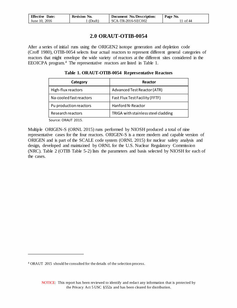
2.0 ORAUT-OTIB-0054
After a series of initial runs using the ORIGEN2 isotope generation and depletion code (Croff 1980), OTIB-0054 selects four actual reactors to represent different general categories of reactors that might envelope the wide variety of reactors at the different sites considered in the EEOICPA program.4 The representative reactors are listed in Table 1.
4 ORAUT 2015 should be consulted for the details of the selection process.
Table 1. ORAUT-OTIB-0054 Representative Reactors
Category Reactor
High-flux reactors Advanced Test Reactor (ATR)
Na-cooled fast reactors Fast Flux Test Facility (FFTF)
Pu production reactors Hanford N-Reactor
Research reactors TRIGA with stainless steel cladding Source: ORAUT 2015.
Multiple ORIGEN-S (ORNL 2015) runs performed by NIOSH produced a total of nine representative cases for the four reactors. ORIGEN-S is a more modern and capable version of ORIGEN and is part of the SCALE code system (ORNL 2015) for nuclear safety analysis and design, developed and maintained by ORNL for the U.S. Nuclear Regulatory Commission (NRC). Table 2 (OTIB Table 5-2) lists the parameters and basis selected by NIOSH for each of the cases.

Effective Date: June 10, 2016
Revision No. 1 (Draft)
Document No./Description: SCA-TR-2016-SEC002
Page No. 12 of 44
NOTICE: This report has been reviewed to identify and redact any information that is protected by the Privacy Act 5 USC §552a and has been cleared for distribution.
Table 2. ORIGEN-S Irradiation Parameters for the Nine Representative Reactor Cases
Case Parameters Basis
ATR 1 Specific power = 2,379.1 MW/MTU Irradiation time = 132.27 days Burnup = 314,684 MWd/MTU
Maximum burnup at nominal power.
ATR 2 Specific power = 8,651.2 MW/MTU Irradiation time = 36.4 days Burnup = 314,904 MWd/MTU
Maximum burnup at maximum assembly power.
ATR 3 Specific power = 2,379.1 MW/MTU Irradiation time = 56 days Burnup = 133,230 MWd/MTU
Nominal burnup at nominal power.
FFTF 1 Specific power = 163.8 MW/MTHM Irradiation time = 929.4 days Burnup = 152,230 MWd/MTHM
Maximum burnup at nominal power.
FFTF 2 Specific power = 163.8 MW/MTHM Irradiation time = 488.3 days Burnup = 79,984 MWd/MTHM
Nominal burnup at nominal power.
N Reactor 1 Specific power = 10.4 MW/MTU Irradiation time = 114.2 days Burnup = 1,188 MWd/MTU
Production of weapons-grade plutonium (nominal 6% Pu-240 content) at nominal power.
N Reactor 2 Specific power = 10.4 MW/MTU Irradiation time = 285.6 days Burnup = 2,970 MWd/MTU
Production of fuel-grade plutonium (nominal 12% Pu-240 content) at nominal power.
TRIGA 1 Specific power = 15.57 MWd/MTU Irradiation time = 730.1 days Burnup = 11,368 MWd/MTU
Maximum burnup at nominal power.
TRIGA 2 Specific power = 15.57 MW/MTU Irradiation time = 115.2 days Burnup = 1994 MWd/MTU
Nominal burnup at nominal power.
Source: Reproduced from ORAUT 2015, Table 5-2.
Effective Date: June 10, 2016
Revision No. 1 (Draft)
Document No./Description: SCA-TR-2016-SEC002
Page No. 13 of 44
NOTICE: This report has been reviewed to identify and redact any information that is protected by the Privacy Act 5 USC §552a and has been cleared for distribution.
3.0 EVALUATION
NIOSH uses OTIB-0054 to determine internal doses to claimants using indicator radionuclides in cases where only gross beta or gross gamma measurements are available. The nine cases of Table 2 are intended to envelope reactor and nuclear fuel types and operating scenarios to which workers might have been exposed. As discussed in Section 1, the screening in this report examines whether it seems likely that OTIB-0054 adequately envelopes the INL reactors listed in Attachment 1 and prioritizes for further investigation those that might not be enveloped by the OTIB-0054 methodology. Table 3 lists (for convenience in finding a particular reactor) all 52 reactors alphabetically (which is also numerically) as shown in Stacy 2000. Priority rankings from Attachment 1 are also included in the last column.
Table 3. List of all INL Reactors
Reactor Name a,b Location Priority Ranking
1. Advanced Reactivity Measurement Facil ity No. 1 (ARMF-I) TRA (Bldg. TRA-660) Low 2. Advanced Reactivity Measurement Facil ity No. 2 (ARMF-II). Renamed Coupled Fast Reactivity Measurement Facil ity (CFRMF) in 1968
TRA (Bldg. TRA-660) Low
3. Advanced Test Reactor (ATR) TRA (Bldg. TRA-670) N/Ac
4. Advanced Test Reactor Critical Facility (ATRC) TRA (Bldg. TRA-670) Low 5. Argonne Fast Source Reactor (AFSR) ANL-W N/Ae
6. Boil ing Water Reactor Experiment No. 1 (BORAX-I) ANL-W N/Ae 7. Boil ing Water Reactor Experiment No. 2 (BORAX-II) ANL-W N/Ae 8. Boil ing Water Reactor Experiment No. 3 (BORAX-III) ANL-W N/Ae 9. Boil ing Water Reactor Experiment No. 4 (BORAX-IV) ANL-W N/Ae 10. Boil ing Water Reactor Experiment No. 5 (BORAX-V) ANL-W N/Ae 11. Cavity Reactor Critical Experiment (CRCE) TAN - WRRTF – LPTF Medium 12. Coupled Fast Reactivity Measurement Facil ity (CFRMF). Formerly named Advanced Reactivity Measurement Facil ity No. 2 (ARMF-II)
TRA (Bldg. TRA-660) Low
13. Critical Experiment Tank (CET) TAN - WRRTF – LPTF Low 14. Engineering Test Reactor (ETR) TRA (Bldg. TRA-642) N/Ac
15. Engineering Test Reactor Critical Facility (ETRC) TRA (Bldg. TRA-654) Low 16. Experimental Beryll ium Oxide Reactor (EBOR) TAN - WRRTF – LPTF (Bldg. TAN-646) N/Af
17. Experimental Breeder Reactor No. I (EBR-I) ANL-W N/Ae 18. Experimental Breeder Reactor No. II (EBR-II) ANL-W N/Ae 19. Experimental Organic Cooled Reactor (EOCR) CFA (vicinity) N/Af
20. Fast Spectrum Refractory Metals Reactor (710) TAN - WRRTF – LPTF Low 21. Gas Cooled Reactor Experiment (GCRE) ARA-III Low 22. Heat Transfer Experiment No. 1 (HTRE-1) TAN - IETF N/Ad
23. Heat Transfer Experiment No. 2 (HTRE-2) TAN - IETF N/Ad
24. Heat Transfer Experiment No. 3 (HTRE-3) TAN - IETF N/Ad
25. High Temperature Marine Propulsion Reactor (630-A) TAN - WRRTF – LPTF Low 26. Hot Critical Experiment (HOTCE) TAN - WRRTF – LPTF Low 27. Large Ship Reactor A (A1W-A) NRF N/Ag
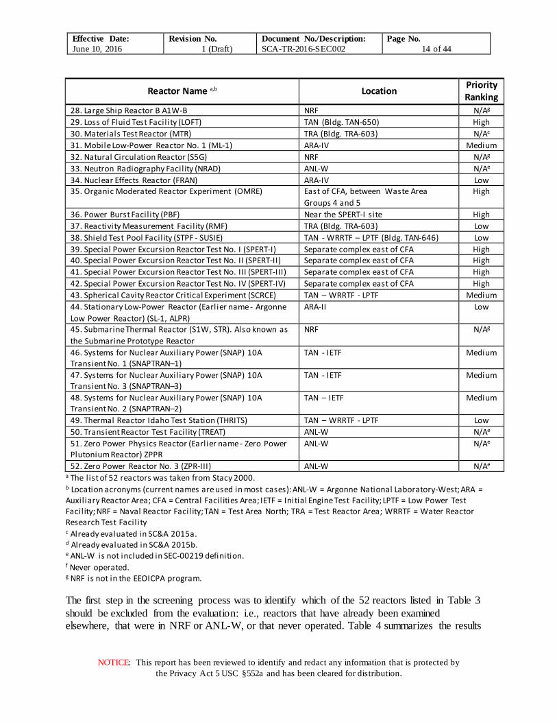
Effective Date: June 10, 2016
Revision No. 1 (Draft)
Document No./Description: SCA-TR-2016-SEC002
Page No. 14 of 44
NOTICE: This report has been reviewed to identify and redact any information that is protected by the Privacy Act 5 USC §552a and has been cleared for distribution.
Reactor Name a,b Location Priority Ranking
28. Large Ship Reactor B A1W-B NRF N/Ag
29. Loss of Fluid Test Facil ity (LOFT) TAN (Bldg. TAN-650) High 30. Materials Test Reactor (MTR) TRA (Bldg. TRA-603) N/Ac
31. Mobile Low-Power Reactor No. 1 (ML-1) ARA-IV Medium 32. Natural Circulation Reactor (S5G) NRF N/Ag
33. Neutron Radiography Facil ity (NRAD) ANL-W N/Ae 34. Nuclear Effects Reactor (FRAN) ARA-IV Low 35. Organic Moderated Reactor Experiment (OMRE) East of CFA, between Waste Area
Groups 4 and 5 High
36. Power Burst Facil ity (PBF) Near the SPERT-I site High 37. Reactivity Measurement Facil ity (RMF) TRA (Bldg. TRA-603) Low 38. Shield Test Pool Facil ity (STPF - SUSIE) TAN - WRRTF – LPTF (Bldg. TAN-646) Low 39. Special Power Excursion Reactor Test No. I (SPERT-I) Separate complex east of CFA High 40. Special Power Excursion Reactor Test No. II (SPERT-II) Separate complex east of CFA High 41. Special Power Excursion Reactor Test No. III (SPERT-III) Separate complex east of CFA High 42. Special Power Excursion Reactor Test No. IV (SPERT-IV) Separate complex east of CFA High 43. Spherical Cavity Reactor Critical Experiment (SCRCE) TAN – WRRTF - LPTF Medium 44. Stationary Low-Power Reactor (Earlier name - Argonne Low Power Reactor) (SL-1, ALPR)
ARA-II Low
45. Submarine Thermal Reactor (S1W, STR). Also known as the Submarine Prototype Reactor
NRF N/Ag
46. Systems for Nuclear Auxil iary Power (SNAP) 10A Transient No. 1 (SNAPTRAN–1)
TAN - IETF Medium
47. Systems for Nuclear Auxil iary Power (SNAP) 10A Transient No. 3 (SNAPTRAN–3)
TAN - IETF Medium
48. Systems for Nuclear Auxil iary Power (SNAP) 10A Transient No. 2 (SNAPTRAN–2)
TAN – IETF Medium
49. Thermal Reactor Idaho Test Station (THRITS) TAN – WRRTF - LPTF Low 50. Transient Reactor Test Facil ity (TREAT) ANL-W N/Ae 51. Zero Power Physics Reactor (Earlier name - Zero Power Plutonium Reactor) ZPPR
ANL-W N/Ae
52. Zero Power Reactor No. 3 (ZPR-III) ANL-W N/Ae a The l ist of 52 reactors was taken from Stacy 2000. b Location acronyms (current names are used in most cases): ANL-W = Argonne National Laboratory-West; ARA = Auxil iary Reactor Area; CFA = Central Facil ities Area; IETF = Initial Engine Test Facil ity; LPTF = Low Power Test Facil ity; NRF = Naval Reactor Facil ity; TAN = Test Area North; TRA = Test Reactor Area; WRRTF = Water Reactor Research Test Facil ity c Already evaluated in SC&A 2015a. d Already evaluated in SC&A 2015b. e ANL-W is not included in SEC-00219 definition. f Never operated. g NRF is not in the EEOICPA program.
The first step in the screening process was to identify which of the 52 reactors listed in Table 3 should be excluded from the evaluation: i.e., reactors that have already been examined elsewhere, that were in NRF or ANL-W, or that never operated. Table 4 summarizes the results
Effective Date: June 10, 2016
Revision No. 1 (Draft)
Document No./Description: SCA-TR-2016-SEC002
Page No. 15 of 44
NOTICE: This report has been reviewed to identify and redact any information that is protected by the Privacy Act 5 USC §552a and has been cleared for distribution.
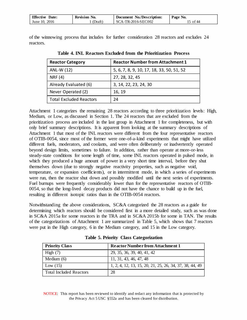
of the winnowing process that includes for further consideration 28 reactors and excludes 24 reactors.
Table 4. INL Reactors Excluded from the Prioritization Process
Reactor Category Reactor Number from Attachment 1
ANL-W (12) 5, 6, 7, 8, 9, 10, 17, 18, 33, 50, 51, 52 NRF (4) 27, 28, 32, 45 Already Evaluated (6) 3, 14, 22, 23, 24, 30 Never Operated (2) 16, 19 Total Excluded Reactors 24
Attachment 1 categorizes the remaining 28 reactors according to three prioritization levels: High, Medium, or Low, as discussed in Section 1. The 24 reactors that are excluded from the prioritization process are included in the last group in Attachment 1 for completeness, but with only brief summary descriptions. It is apparent from looking at the summary descriptions of Attachment 1 that most of the INL reactors were different from the four representative reactors of OTIB-0054, since most of the former were one-of-a-kind experiments that might have utilized different fuels, moderators, and coolants, and were often deliberately or inadvertently operated beyond design limits, sometimes to failure. In addition, rather than operate at more-or-less steady-state conditions for some length of time, some INL reactors operated in pulsed mode, in which they produced a huge amount of power in a very short time interval, before they shut themselves down (due to strongly negative reactivity properties, such as negative void, temperature, or expansion coefficients), or in intermittent mode, in which a series of experiments were run, then the reactor shut down and possibly modified until the next series of experiments. Fuel burnups were frequently considerably lower than for the representative reactors of OTIB-0054, so that the long-lived decay products did not have the chance to build up in the fuel, resulting in different isotopic ratios than in the OTIB-0054 reactors.
Notwithstanding the above considerations, SC&A categorized the 28 reactors as a guide for determining which reactors should be considered first in a more detailed study, such as was done in SC&A 2015a for some reactors in the TRA and in SC&A 2015b for some in TAN. The results of the categorizations of Attachment 1 are summarized in Table 5, which shows that 7 reactors were put in the High category, 6 in the Medium category, and 15 in the Low category.
Table 5. Priority Class Categorization
Priority Class Reactor Number from Attachment 1 High (7) 29, 35, 36, 39, 40, 41, 42 Medium (6) 11, 31, 43, 46, 47, 48 Low (15) 1, 2, 4, 12, 13, 15, 20, 21, 25, 26, 34, 37, 38, 44, 49 Total Included Reactors 28
Effective Date: June 10, 2016
Revision No. 1 (Draft)
Document No./Description: SCA-TR-2016-SEC002
Page No. 16 of 44
NOTICE: This report has been reviewed to identify and redact any information that is protected by the Privacy Act 5 USC §552a and has been cleared for distribution.
The rationale behind the categorizations shown in Table 5 appear in Attachment 1. SC&A recommends that the seven reactors in the High priority class be investigated first, with the results presented in a single report. For convenience and efficiency, the four SPERT reactors (Nos. 39–42) would be grouped together. Also in the High priority class are the LOFT (No. 29), OMRE (No. 35), and PBF (No. 36) reactors.

Effective Date: June 10, 2016
Revision No. 1 (Draft)
Document No./Description: SCA-TR-2016-SEC002
Page No. 17 of 44
NOTICE: This report has been reviewed to identify and redact any information that is protected by the Privacy Act 5 USC §552a and has been cleared for distribution.
4.0 REFERENCES
AEC 1958. Proceedings of the SRE-OMRE Forum, Los Angeles, CA, February 12 and 13, 1958, TID-7553, U.S. Atomic Energy Commission. May 1958.
Aerojet-General 1960. The ML-1 Design Report, IDO-28550. May 16, 1960. Available at http://digital.library.unt.edu/ark:/67531/metadc100219/m2/1/high_res_d/metadc100219.pdf
Aerojet-General 1963. Army Gas-Cooled Reactor Systems Program: Final Summary Report of the Gas-Cooled Reactor Experiment-I, IDO-28598. October 1963. Available at http://digital.library.unt.edu/ark:/67531/metadc100222/m2/1/high_res_d/metadc100222.pdf
Croff 1980. Croff, A. G., ORIGEN2 – A Revised and Updated Version of the Oak Ridge Isotope Generation and Depletion Code, ORNL-5621, Oak Ridge National Laboratory. July 1980. [SRDB Ref. ID 23569]
INL 2009. Power Burst Facility: U(18)O2CaO-ZrO2 Fuel Rods in Water, INL/EXT-09-15446, Idaho National Laboratory, Idaho Falls, ID. September 2009. [SRDB Ref. ID 136135]
Lofthouse and Kunze 1971. Lofthouse, J. H., and J. F. Kunze, Spherical Gas Core Reactor Critical Experiment, IN-1443, NASA CR-72781, Idaho Nuclear Corporation for National Aeronautics and Space Administration. February 1971. [SRDB Ref. ID 135872]
Modro et al. 1989. Modro, S. M., S. N. Aksan, V. T. Berta, and A. B. Wahba, Review of LOFT Large Break Experiments: OECD LOFT Project, NUREG/IA-0028, U.S. Nuclear Regulatory Commission. October 1989. Available at http://www.nrc.gov/reading-rm/doc-collections/nuregs/agreement/ia0028/#pub- info
Montgomery et al. 1957. Montgomery, C. R., J. A. Norberg, and T. R. Wilson, Summary of the SPERT-I, -II, and -III Reactor Facilities, AEC Research and Development Report IDO-16418, U.S. Atomic Energy Commission. November 1, 1957. [SRDB Ref. ID 136833]
Nace et al. 1972. Nace, R. L., M. Deutsch, and P. T. Voegeli, Physical Environment of the National Reactor Testing Station, Idaho – A Summary: Geology, Hydrology, and Waste Management at the National Reactor Testing Station, Idaho, Geological Survey Professional Paper 725-A, U.S> Department of the Interior, Geological Survey. 1972. [SRDB Ref. ID 138052]
NIOSH 2015a. SEC Petition Evaluation Report: Petition SEC-00219, Revision 0, National Institute for Occupational Safety and Health. March 12, 2015.
NIOSH 2015b. SEC Petition Evaluation Report: Petition SEC-00219, Revision 1, National Institute for Occupational Safety and Health. July 21, 2015.

Effective Date: June 10, 2016
Revision No. 1 (Draft)
Document No./Description: SCA-TR-2016-SEC002
Page No. 18 of 44
NOTICE: This report has been reviewed to identify and redact any information that is protected by the Privacy Act 5 USC §552a and has been cleared for distribution.
ORAUT 2010. Idaho National Laboratory and Argonne National Laboratory-West – Site Description, ORAUT-TKBS-0007-2, Revision 4, Oak Ridge Associated Universities. August 2, 2010.
ORAUT 2015. Fission and Activation Product Assignment for Internal Dose-Related Gross Beta and Gross Gamma Analyses, ORAUT-OTIB-0054, Revision 3, Oak Ridge Associated Universities. February 6, 2015.
ORNL 2015. SCALE: A Comprehensive Modeling and Simulation Suite for Nuclear Safety Analysis and Design, Oak Ridge National Laboratory. Accessed February 18, 2016, at http://scale.ornl.gov.
Reeder and Berta 1979. Reeder, D. L., and V. T. Berta, The Loss-of-Fluid Test (LOFT) Facility, 14th Annual Intersociety Energy Conversion Conference, Boston, MA. August 5, 1979.
SC&A 2015a. NIOSH SEC-00219: Test Reactor Area Modeling, SCA-SEC-2015-0074-C, Revision 0, SC&A, Inc. September 28, 2015.
SC&A 2015b. Review of NIOSH Strategy for Reconstructing Internal Doses to Workers at Test Area North, SCA-TR-2015-SEC0074A, Revision 0, SC&A, Inc. September 28, 2015.
SC&A 2016. INL SEC-00219 Reactor Prioritization for Evaluation of ORAUT—OTIB-0054 Applicability, SCA-TR-2016-SEC0002, Revision 0, SC&A Inc. March 2, 2016.
Stacy 2000. Stacy, Susan M., Proving the Principle: A History of the Idaho National Engineering and Environmental Laboratory 1949-1999, DOE/ID-10799, Idaho Operations Office, U.S. Department of Energy, Idaho Falls, ID. 2000. [SRDB Ref. ID 1152, 135760]
Stillman and Mead 1965. Stillman, D. B., and S. W. Mead, The FRAN Prompt Burst Reactor, Lawrence Radiation Laboratory, University of California, Livermore, UCRL-14413. September 29, 1965.
Effective Date: June 10, 2016
Revision No. 1 (Draft)
Document No./Description: SCA-TR-2016-SEC002
Page No. 19 of 44
NOTICE: This report has been reviewed to identify and redact any information that is protected by the Privacy Act 5 USC §552a and has been cleared for distribution.
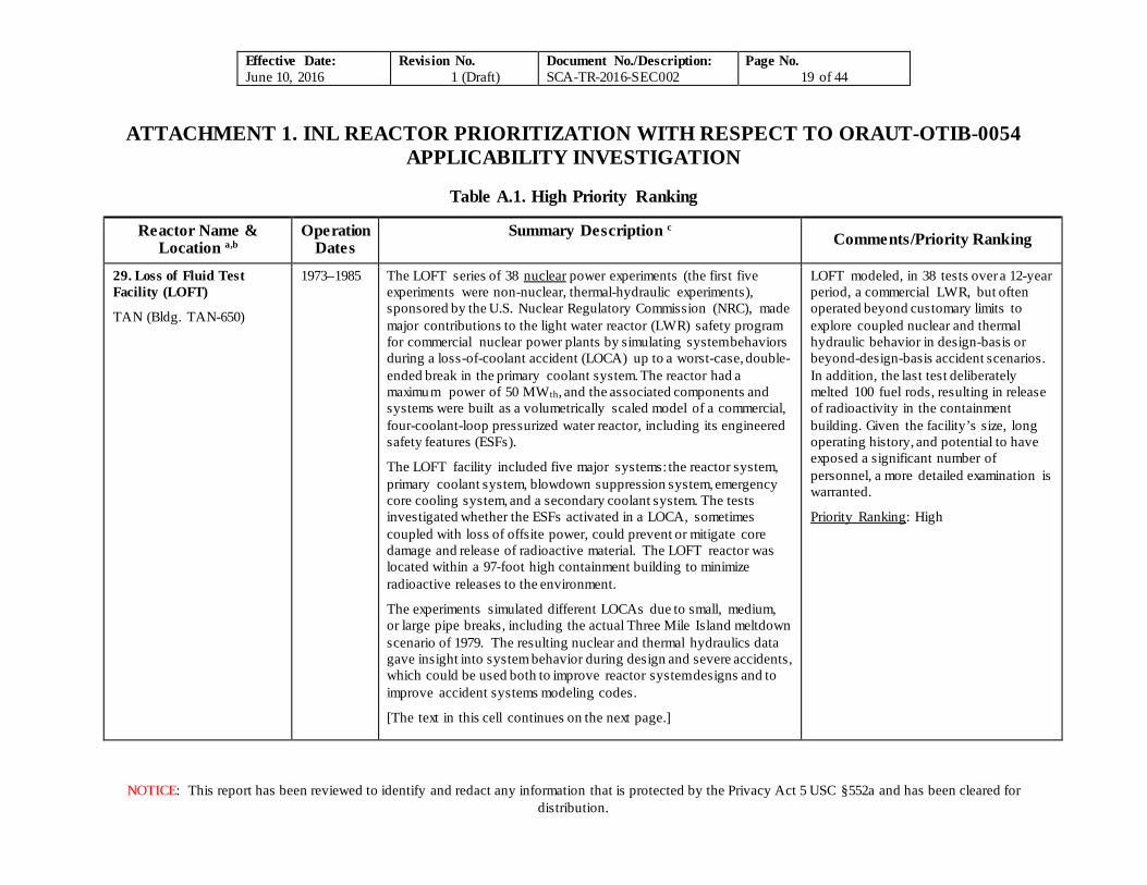
ATTACHMENT 1. INL REACTOR PRIORITIZATION WITH RESPECT TO ORAUT-OTIB-0054 APPLICABILITY INVESTIGATION
Table A.1. High Priority Ranking
Reactor Name & Location a,b
Operation Dates
Summary Description cComments/Priority Ranking
29. Loss of Fluid TestFacility (LOFT)
TAN (Bldg. TAN-650)
1973–1985 The LOFT series of 38 nuclear power experiments (the first five experiments were non-nuclear, thermal-hydraulic experiments), sponsored by the U.S. Nuclear Regulatory Commission (NRC), made major contributions to the light water reactor (LWR) safety program for commercial nuclear power plants by simulating system behaviors during a loss-of-coolant accident (LOCA) up to a worst-case, double-ended break in the primary coolant system. The reactor had a maximum power of 50 MWth, and the associated components and systems were built as a volumetrically scaled model of a commercial, four-coolant-loop pressurized water reactor, including its engineered safety features (ESFs).
The LOFT facility included five major systems: the reactor system, primary coolant system, blowdown suppression system, emergency core cooling system, and a secondary coolant system. The tests investigated whether the ESFs activated in a LOCA, sometimes coupled with loss of offsite power, could prevent or mitigate core damage and release of radioactive material. The LOFT reactor was located within a 97-foot high containment building to minimize radioactive releases to the environment.
The experiments simulated different LOCAs due to small, medium, or large pipe breaks, including the actual Three Mile Island meltdown scenario of 1979. The resulting nuclear and thermal hydraulics data gave insight into system behavior during design and severe accidents, which could be used both to improve reactor system designs and to improve accident systems modeling codes.
[The text in this cell continues on the next page.]
LOFT modeled, in 38 tests over a 12-year period, a commercial LWR, but often operated beyond customary limits to explore coupled nuclear and thermal hydraulic behavior in design-basis or beyond-design-basis accident scenarios. In addition, the last test deliberately melted 100 fuel rods, resulting in release of radioactivity in the containment building. Given the facility’s size, long operating history, and potential to have exposed a significant number of personnel, a more detailed examination is warranted.
Priority Ranking: High
Effective Date: June 10, 2016
Revision No. 1 (Draft)
Document No./Description: SCA-TR-2016-SEC002
Page No. 20 of 44
NOTICE: This report has been reviewed to identify and redact any information that is protected by the Privacy Act 5 USC §552a and has been cleared for distribution.
Reactor Name & Location a,b
Operation Dates
Summary Description cComments/Priority Ranking
[Row continued from previous page; no additional text in this cell.]
[Row continued from previous page; no additional text in this cell.]
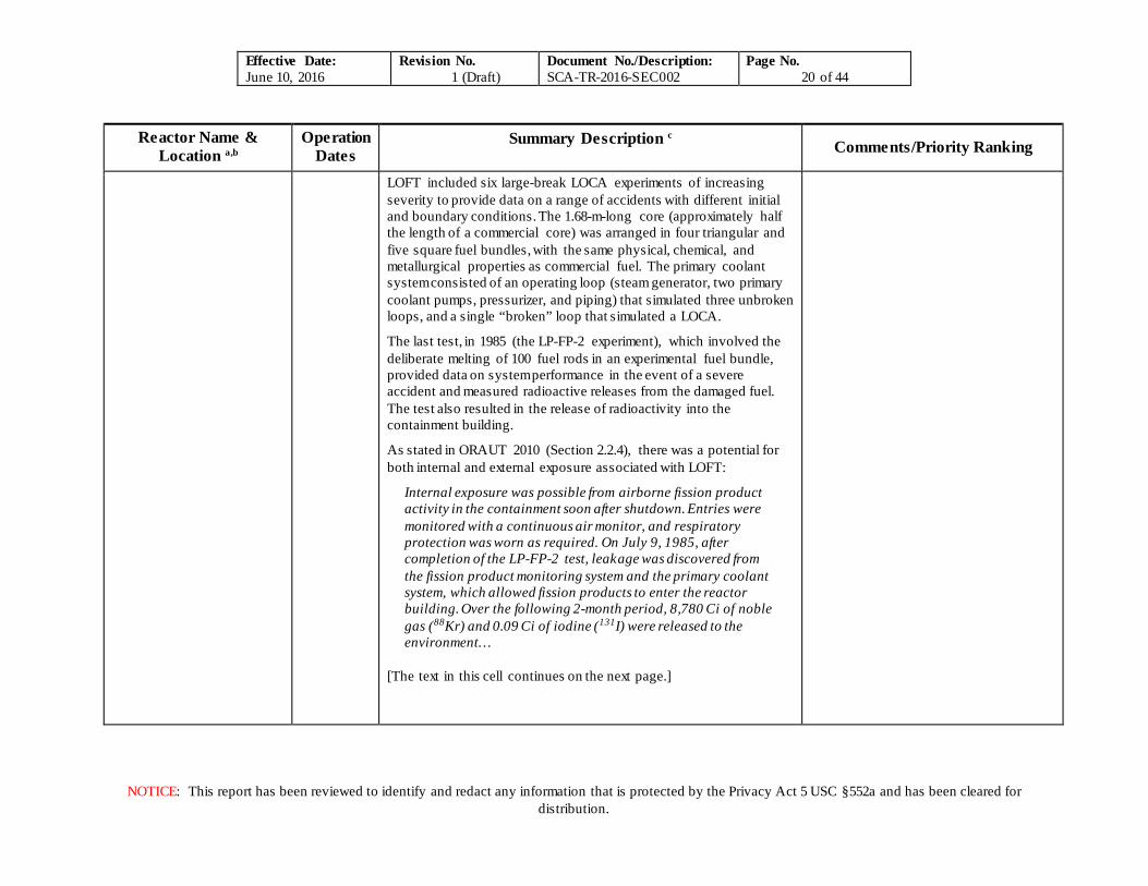
LOFT included six large-break LOCA experiments of increasing severity to provide data on a range of accidents with different initial and boundary conditions. The 1.68-m-long core (approximately half the length of a commercial core) was arranged in four triangular and five square fuel bundles, with the same physical, chemical, and metallurgical properties as commercial fuel. The primary coolant system consisted of an operating loop (steam generator, two primary coolant pumps, pressurizer, and piping) that simulated three unbroken loops, and a single “broken” loop that simulated a LOCA.
The last test, in 1985 (the LP-FP-2 experiment), which involved the deliberate melting of 100 fuel rods in an experimental fuel bundle, provided data on system performance in the event of a severe accident and measured radioactive releases from the damaged fuel. The test also resulted in the release of radioactivity into the containment building.
As stated in ORAUT 2010 (Section 2.2.4), there was a potential for both internal and external exposure associated with LOFT:
Internal exposure was possible from airborne fission product activity in the containment soon after shutdown. Entries were monitored with a continuous air monitor, and respiratory protection was worn as required. On July 9, 1985, after completion of the LP-FP-2 test, leakage was discovered from the fission product monitoring system and the primary coolant system, which allowed fission products to enter the reactor building. Over the following 2-month period, 8,780 Ci of noble gas (88Kr) and 0.09 Ci of iodine (131I) were released to the environment…
[The text in this cell continues on the next page.]
[Row continued from previous page; no additional text in this cell.]
Effective Date: June 10, 2016
Revision No. 1 (Draft)
Document No./Description: SCA-TR-2016-SEC002
Page No. 21 of 44
NOTICE: This report has been reviewed to identify and redact any information that is protected by the Privacy Act 5 USC §552a and has been cleared for distribution.
Reactor Name & Location a,b
Operation Dates
Summary Description cComments/Priority Ranking
[Row continued from previous page; no additional text in this cell.]
[Row continued from previous page; no additional text in this cell.]
External exposure occurred to personnel who worked inside the containment vessel or on the reactor’s primary system or the sample systems. During initial entry after a test, the fields in containment were ≥100 mrad/hr beta-gamma. The short-lived fission products would decay rapidly and reduce the general fields to ≤10 mrad/hr beta-gamma.
References Modro et al. 1989 Reeder and Berta 1979
[Row continued from previous page; no additional text in this cell.]
35. Organic Moderated Reactor Experiment (OMRE)
Separate area a few miles east of Central Facilities Area (CFA), between Waste Area Groups 4 and 5.
1957 – 1963
The OMRE reactor, built by Atomics International, was part of an Atomic Energy Commission (AEC) program to assess the feasibility and determine the nuclear and engineering technical basis of different reactor concepts in support of an emerging civilian nuclear power industry. OMRE used a waxy liquid hydrocarbon rather than water or a liquid metal as both coolant and moderator. The relatively low-power (5–10 MWth), critical reactor tested various types and configurations of highly enriched uranium dioxide (UO2) fuel elements and gathered performance data on the coolant as well as nuclear data. The waxy coolant was thought to have some advantages over “conventional” coolants since it allows low-pressure operation, solidifies at low temperatures, and does not corrode metals.
The reactor achieved initial criticality in September 1957 and operated almost continuously until April 1963. The Experimental Organic Cooled Reactor (EOCR) was designed to follow OMRE, which lacked test loops, but was cancelled by the AEC near the end of construction in 1962.
References Nace et al. 1972 USAEC 1958
OMRE operated at relatively low power levels, but did so nearly continuously for several years. In addition, it is doubtful whether OMRE would be adequately enveloped by any of the OTIB-0054 cases because it used an organic coolant and moderator. Hence, it should be investigated further.
Priority Ranking: High

Effective Date: June 10, 2016
Revision No. 1 (Draft)
Document No./Description: SCA-TR-2016-SEC002
Page No. 22 of 44
NOTICE: This report has been reviewed to identify and redact any information that is protected by the Privacy Act 5 USC §552a and has been cleared for distribution.
Reactor Name & Location a,b
Operation Dates
Summary Description cComments/Priority Ranking
36. Power Burst Facility (PBF)
At the SPERT-I site.
1972–1985 The PBF continued the reactor safety program begun with the Special Power Excursion Reactor Test (SPERT) series of facilities but was much larger than the SPERT reactors and was built on the site of SPERT-I. Fuel and cladding combinations were varied and tested to failure. Transient testing, including LOCA scenarios that modeled design-basis and severe accident conditions at a commercial nuclear power plant, led to fuel and cladding damage accompanied by the subsequent evolution of hydrogen and the release of fission products to the reactor containment. Simulated LOCAs and other severe accident tests were performed in an experimental loop within the reactor core. Test data were used by the NRC to develop and test reactor transient codes.
As its name implies, the PBF could produce very high, short-duration (millisecond) power excursions that were self-limiting. It could operate at a steady-state power of 20 MWth for a short period of time before initiating a very short super-critical power burst.
The reactor was water-cooled and reflected, and used uranium-oxide-fuel with stainless steel cladding. The core consisted of a square array of 121 square cells, 5.85 in × 5.85 in × 60 in, with an active fuel region of about 36 in located in a pressure vessel. Different fuel configurations, compositions, and enrichments were tested. At least one experimental series had an enrichment of 18.31%. Some of the experiments used previously irradiated fuel (e.g., 38,000 MWd/MTU) to better simulate accident conditions.
[The text in this cell continues on the next page.]
The PBF operated for over 10 years, tested a variety of new and previously irradiated fuel often to fuel failure, and, for at least part of the time, operated with fuel enrichments greater than used in a commercial nuclear power plant, thus putting it outside the range of the nine representative cases of OTIB-0054.
Priority Ranking: High
Effective Date: June 10, 2016
Revision No. 1 (Draft)
Document No./Description: SCA-TR-2016-SEC002
Page No. 23 of 44
NOTICE: This report has been reviewed to identify and redact any information that is protected by the Privacy Act 5 USC §552a and has been cleared for distribution.
Reactor Name & Location a,b
Operation Dates
Summary Description cComments/Priority Ranking
[Row continued from previous page; no additional text in this cell.]
[Row continued tfrom previous page; no additional text in this cell.]
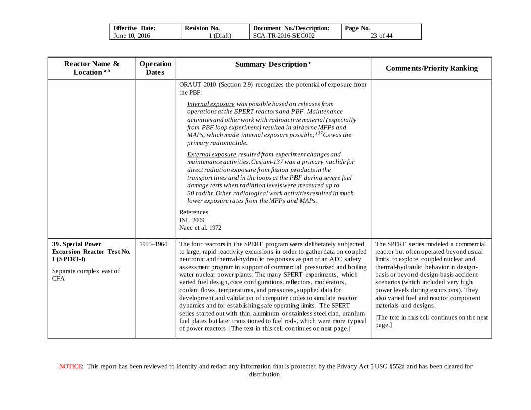
ORAUT 2010 (Section 2.9) recognizes the potential of exposure from he PBF:
Internal exposure was possible based on releases from operations at the SPERT reactors and PBF. Maintenance activities and other work with radioactive material (especially from PBF loop experiment) resulted in airborne MFPs and MAPs, which made internal exposure possible; 137Cs was the primary radionuclide.
External exposure resulted from experiment changes and maintenance activities. Cesium-137 was a primary nuclide for direct radiation exposure from fission products in the transport lines and in the loops at the PBF during severe fuel damage tests when radiation levels were measured up to 50 rad/hr. Other radiological work activities resulted in much lower exposure rates from the MFPs and MAPs.
References INL 2009 Nace et al. 1972
[Row continued from previous page; no additional text in this cell.]
39. Special PowerExcursion Reactor Test No. I (SPERT-I)
Separate complex east of CFA
1955–1964 The four reactors in the SPERT program were deliberately subjected to large, rapid reactivity excursions in order to gather data on coupled neutronic and thermal-hydraulic responses as part of an AEC safety assessment program in support of commercial pressurized and boiling water nuclear power plants. The many SPERT experiments, which varied fuel design, core configurations, reflectors, moderators, coolant flows, temperatures, and pressures, supplied data for development and validation of computer codes to simulate reactor dynamics and for establishing safe operating limits. The SPERT series started out with thin, aluminum or stainless steel clad, uranium fuel plates but later transitioned to fuel rods, which were more typical of power reactors. [The text in this cell continues on next page.]
The SPERT series modeled a commercial reactor but often operated beyond usual limits to explore coupled nuclear and thermal-hydraulic behavior in design-basis or beyond-design-basis accident scenarios (which included very high power levels during excursions). They also varied fuel and reactor component materials and designs.
[The text in this cell continues on the next page.]
Effective Date: June 10, 2016
Revision No. 1 (Draft)
Document No./Description: SCA-TR-2016-SEC002
Page No. 24 of 44
NOTICE: This report has been reviewed to identify and redact any information that is protected by the Privacy Act 5 USC §552a and has been cleared for distribution.
Reactor Name & Location a,b
Operation Dates
Summary Description cComments/Priority Ranking
[Row continued from previous page; no additional text in this cell.]
[Row continued from previous page; no additional text in this cell.]
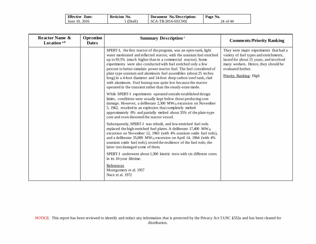
SPERT-I, the first reactor of the program, was an open-tank, light water moderated and reflected reactor, with the uranium fuel enriched up to 93.5% (much higher than in a commercial reactor). Some experiments were also conducted with fuel enriched only a few percent to better simulate power reactor fuel. The fuel considered of plate type uranium and aluminum fuel assemblies (about 25 inches long) in a 4-foot diameter and 14-foot deep carbon steel tank, clad with aluminum. Fuel burnup was quite low because the reactor operated in the transient rather than the steady-state mode.
While SPERT-I experiments operated outside established design limits, conditions were usually kept below those producing core damage. However, a deliberate 2,300 MWth excursion on November 5, 1962, resulted in an explosion that completely melted approximately 8% and partially melted about 35% of the plate-type core and even distorted the reactor vessel.
Subsequently, SPERT-I was rebuilt, and low-enriched fuel rods replaced the high-enriched fuel plates. A deliberate 17,400 MWth excursion on November 12, 1963 (with 4% uranium oxide fuel rods), and a deliberate 35,000 MWth excursion on April 14, 1964 (with 4% uranium oxide fuel rods), tested the resilience of the fuel rods; the latter test damaged some of them.
SPERT-I underwent about 1,300 kinetic tests with six different cores in its 10-year lifetime.
References Montgomery et al. 1957 Nace et al. 1972
They were major experiments that had a variety of fuel types and enrichments, lasted for about 15 years, and involved many workers. Hence, they should be evaluated further.
Priority Ranking: High
Effective Date: June 10, 2016
Revision No. 1 (Draft)
Document No./Description: SCA-TR-2016-SEC002
Page No. 25 of 44
NOTICE: This report has been reviewed to identify and redact any information that is protected by the Privacy Act 5 USC §552a and has been cleared for distribution.
Reactor Name & Location a,b
Operation Dates
Summary Description cComments/Priority Ranking
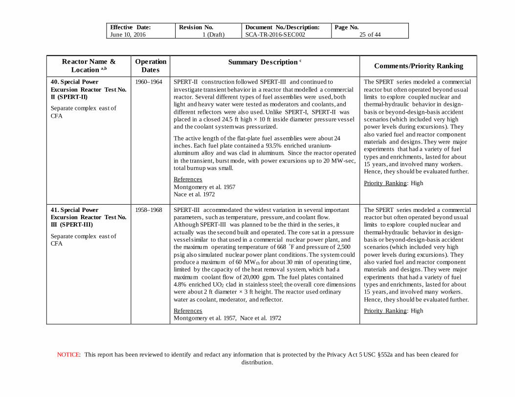
40. Special PowerExcursion Reactor Test No. II (SPERT-II)
Separate complex east of CFA
1960–1964 SPERT-II construction followed SPERT-III and continued to investigate transient behavior in a reactor that modelled a commercial reactor. Several different types of fuel assemblies were used, both light and heavy water were tested as moderators and coolants, and different reflectors were also used. Unlike SPERT-I, SPERT-II was placed in a closed 24.5 ft high × 10 ft inside diameter pressure vessel and the coolant system was pressurized.
The active length of the flat-plate fuel assemblies were about 24 inches. Each fuel plate contained a 93.5% enriched uranium-aluminum alloy and was clad in aluminum. Since the reactor operated in the transient, burst mode, with power excursions up to 20 MW-sec, total burnup was small.
References Montgomery et al. 1957 Nace et al. 1972
The SPERT series modeled a commercial reactor but often operated beyond usual limits to explore coupled nuclear and thermal-hydraulic behavior in design-basis or beyond-design-basis accident scenarios (which included very high power levels during excursions). They also varied fuel and reactor component materials and designs. They were major experiments that had a variety of fuel types and enrichments, lasted for about 15 years, and involved many workers. Hence, they should be evaluated further.
Priority Ranking: High
41. Special PowerExcursion Reactor Test No. III (SPERT-III)
Separate complex east of CFA
1958–1968 SPERT-III accommodated the widest variation in several important parameters, such as temperature, pressure, and coolant flow. Although SPERT-III was planned to be the third in the series, it actually was the second built and operated. The core sat in a pressure vessel similar to that used in a commercial nuclear power plant, and the maximum operating temperature of 668 °F and pressure of 2,500 psig also simulated nuclear power plant conditions. The system could produce a maximum of 60 MWth for about 30 min of operating time, limited by the capacity of the heat removal system, which had a maximum coolant flow of 20,000 gpm. The fuel plates contained 4.8% enriched UO2 clad in stainless steel; the overall core dimensions were about 2 ft diameter × 3 ft height. The reactor used ordinary water as coolant, moderator, and reflector.
References Montgomery et al. 1957, Nace et al. 1972
The SPERT series modeled a commercial reactor but often operated beyond usual limits to explore coupled nuclear and thermal-hydraulic behavior in design-basis or beyond-design-basis accident scenarios (which included very high power levels during excursions). They also varied fuel and reactor component materials and designs. They were major experiments that had a variety of fuel types and enrichments, lasted for about 15 years, and involved many workers. Hence, they should be evaluated further.
Priority Ranking: High
Effective Date: June 10, 2016
Revision No. 1 (Draft)
Document No./Description: SCA-TR-2016-SEC002
Page No. 26 of 44
NOTICE: This report has been reviewed to identify and redact any information that is protected by the Privacy Act 5 USC §552a and has been cleared for distribution.
Reactor Name & Location a,b
Operation Dates
Summary Description cComments/Priority Ranking
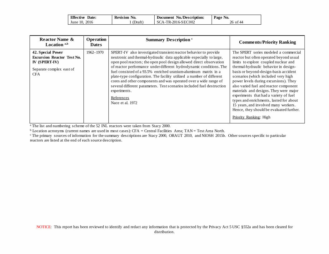
42. Special PowerExcursion Reactor Test No. IV (SPERT-IV)
Separate complex east of CFA
1962–1970 SPERT-IV also investigated transient reactor behavior to provide neutronic and thermal-hydraulic data applicable especially to large, open pool reactors; the open pool design allowed direct observation of reactor performance under different hydrodynamic conditions. The fuel consisted of a 93.5% enriched uranium-aluminum matrix in a plate-type configuration. The facility utilized a number of different cores and other components and was operated over a wide range of several different parameters. Test scenarios included fuel destruction experiments.
References Nace et al. 1972
The SPERT series modeled a commercial reactor but often operated beyond usual limits to explore coupled nuclear and thermal-hydraulic behavior in design-basis or beyond-design-basis accident scenarios (which included very high power levels during excursions). They also varied fuel and reactor component materials and designs. They were major experiments that had a variety of fuel types and enrichments, lasted for about 15 years, and involved many workers. Hence, they should be evaluated further.
Priority Ranking: High
a The list and numbering scheme of the 52 INL reactors were taken from Stacy 2000. b Location acronyms (current names are used in most cases): CFA = Central Facilities Area; TAN = Test Area North. c The primary sources of information for the summary descriptions are Stacy 2000, ORAUT 2010, and NIOSH 2015b. Other sources specific to particular reactors are listed at the end of each source description.
Effective Date: June 10, 2016
Revision No. 1 (Draft)
Document No./Description: SCA-TR-2016-SEC002
Page No. 27 of 44
NOTICE: This report has been reviewed to identify and redact any information that is protected by the Privacy Act 5 USC §552a and has been cleared for distribution.
Table A.2. Medium Priority Ranking Reactor Name &
Location a,b Operation
Dates Summary Description c Comments/Priority Ranking
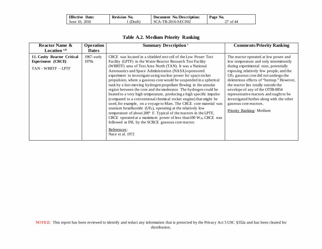
11. Cavity Reactor Critical Experiment (CRCE)
TAN - WRRTF – LPTF
1967–early 1970s
CRCE was located in a shielded test cell of the Low Power Test Facility (LPTF) in the Water Reactor Research Test Facility (WRRTF) area of Test Area North (TAN). It was a National Aeronautics and Space Administration (NASA)-sponsored experiment to investigate using nuclear power for space rocket propulsion, where a gaseous core would be suspended in a spherical tank by a fast-moving hydrogen propellant flowing in the annular region between the core and the moderator. The hydrogen could be heated to a very high temperature, producing a high specific impulse (compared to a conventional chemical rocket engine) that might be used, for example, on a voyage to Mars. The CRCE core material was uranium hexafluoride (UF6), operating at the relatively low temperature of about 200° F. Typical of the reactors in the LPTF, CRCE operated at a maximum power of less than100 Wth. CRCE was followed at INL by the SCRCE gaseous core reactor.
References: Nace et al. 1972
The reactor operated at low power and low temperature and only intermittently during experimental runs, potentially exposing relatively few people, and the UF6 gaseous core did not undergo the deleterious effects of “burnup.” However, the reactor lies totally outside the envelope of any of the OTIB-0054 representative reactors and ought to be investigated further along with the other gaseous core reactors.
Priority Ranking: Medium
Effective Date: June 10, 2016
Revision No. 1 (Draft)
Document No./Description: SCA-TR-2016-SEC002
Page No. 28 of 44
NOTICE: This report has been reviewed to identify and redact any information that is protected by the Privacy Act 5 USC §552a and has been cleared for distribution.
Reactor Name & Location a,b
Operation Dates
Summary Description c Comments/Priority Ranking
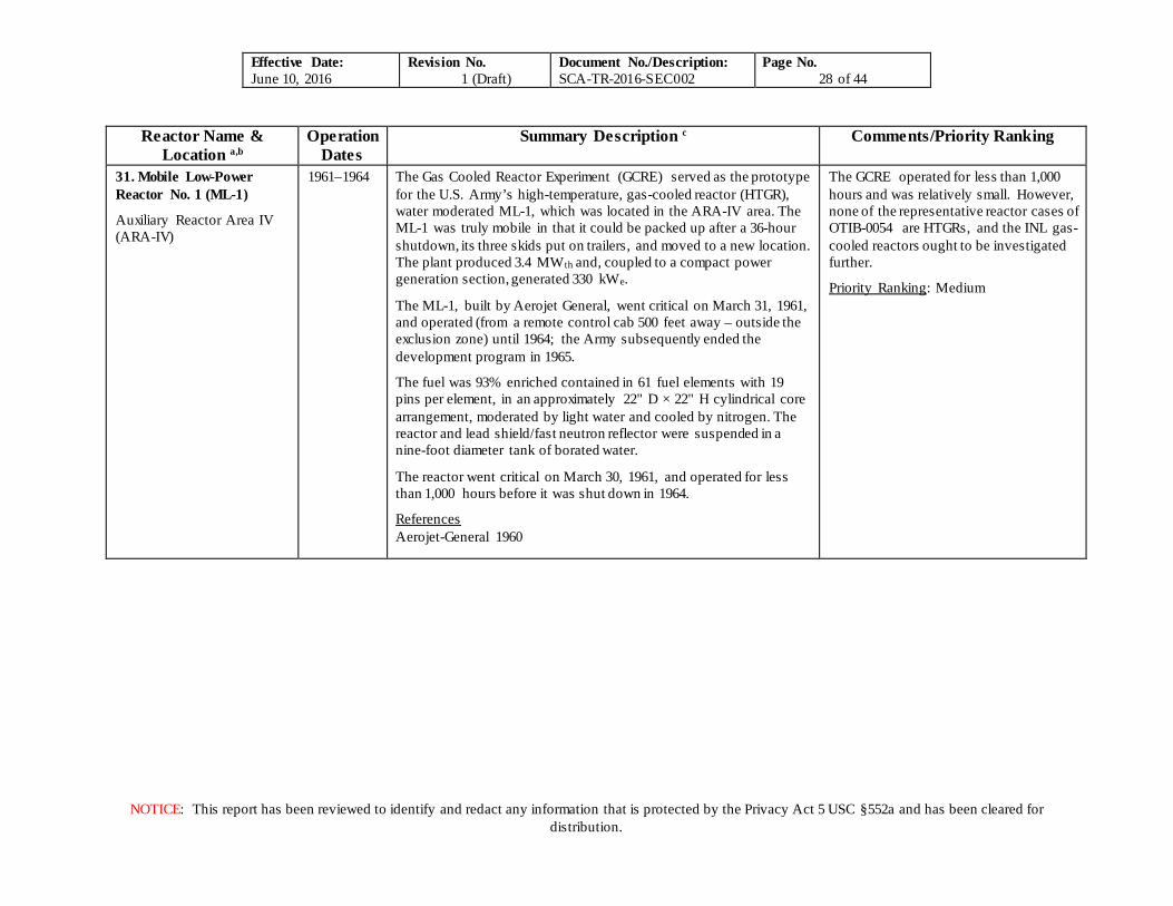
31. Mobile Low-Power Reactor No. 1 (ML-1)
Auxiliary Reactor Area IV (ARA-IV)
1961–1964 The Gas Cooled Reactor Experiment (GCRE) served as the prototype for the U.S. Army’s high-temperature, gas-cooled reactor (HTGR), water moderated ML-1, which was located in the ARA-IV area. The ML-1 was truly mobile in that it could be packed up after a 36-hour shutdown, its three skids put on trailers, and moved to a new location. The plant produced 3.4 MWth and, coupled to a compact power generation section, generated 330 kWe.
The ML-1, built by Aerojet General, went critical on March 31, 1961, and operated (from a remote control cab 500 feet away – outside the exclusion zone) until 1964; the Army subsequently ended the development program in 1965.
The fuel was 93% enriched contained in 61 fuel elements with 19 pins per element, in an approximately 22" D × 22" H cylindrical core arrangement, moderated by light water and cooled by nitrogen. The reactor and lead shield/fast neutron reflector were suspended in a nine-foot diameter tank of borated water.
The reactor went critical on March 30, 1961, and operated for less than 1,000 hours before it was shut down in 1964.
References Aerojet-General 1960
The GCRE operated for less than 1,000 hours and was relatively small. However, none of the representative reactor cases of OTIB-0054 are HTGRs, and the INL gas-cooled reactors ought to be investigated further.
Priority Ranking: Medium
Effective Date: June 10, 2016
Revision No. 1 (Draft)
Document No./Description: SCA-TR-2016-SEC002
Page No. 29 of 44
NOTICE: This report has been reviewed to identify and redact any information that is protected by the Privacy Act 5 USC §552a and has been cleared for distribution.
Reactor Name & Location a,b
Operation Dates
Summary Description c Comments/Priority Ranking
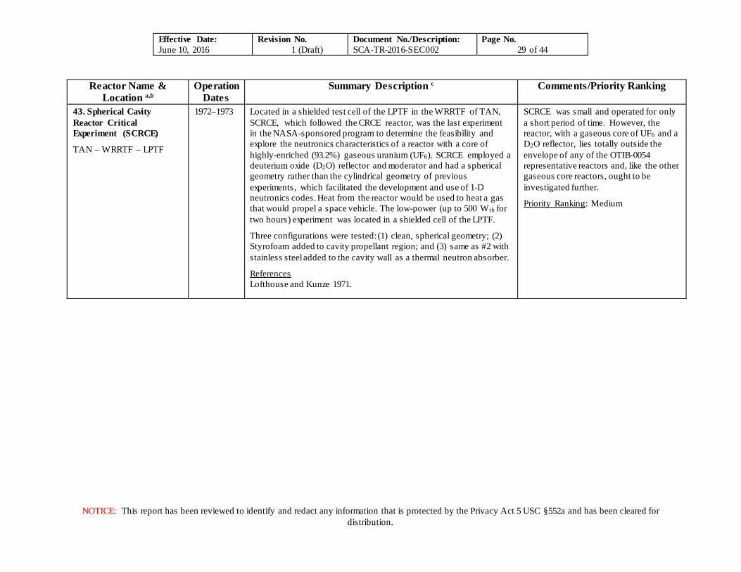
43. Spherical Cavity Reactor Critical Experiment (SCRCE)
TAN – WRRTF – LPTF
1972–1973 Located in a shielded test cell of the LPTF in the WRRTF of TAN, SCRCE, which followed the CRCE reactor, was the last experiment in the NASA-sponsored program to determine the feasibility and explore the neutronics characteristics of a reactor with a core of highly-enriched (93.2%) gaseous uranium (UF6). SCRCE employed a deuterium oxide (D2O) reflector and moderator and had a spherical geometry rather than the cylindrical geometry of previous experiments, which facilitated the development and use of 1-D neutronics codes. Heat from the reactor would be used to heat a gas that would propel a space vehicle. The low-power (up to 500 Wth for two hours) experiment was located in a shielded cell of the LPTF.
Three configurations were tested: (1) clean, spherical geometry; (2) Styrofoam added to cavity propellant region; and (3) same as #2 with stainless steel added to the cavity wall as a thermal neutron absorber.
References Lofthouse and Kunze 1971.
SCRCE was small and operated for only a short period of time. However, the reactor, with a gaseous core of UF6 and a D2O reflector, lies totally outside the envelope of any of the OTIB-0054 representative reactors and, like the other gaseous core reactors, ought to be investigated further.
Priority Ranking: Medium
Effective Date: June 10, 2016
Revision No. 1 (Draft)
Document No./Description: SCA-TR-2016-SEC002
Page No. 30 of 44
NOTICE: This report has been reviewed to identify and redact any information that is protected by the Privacy Act 5 USC §552a and has been cleared for distribution.
Reactor Name & Location a,b
Operation Dates
Summary Description c Comments/Priority Ranking
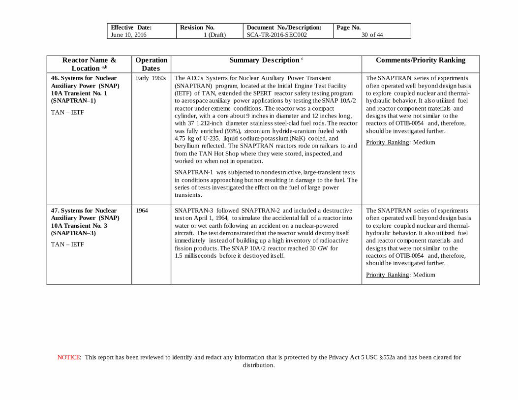
46. Systems for Nuclear Auxiliary Power (SNAP) 10A Transient No. 1 (SNAPTRAN–1)
TAN – IETF
Early 1960s The AEC’s Systems for Nuclear Auxiliary Power Transient (SNAPTRAN) program, located at the Initial Engine Test Facility (IETF) of TAN, extended the SPERT reactor safety testing program to aerospace auxiliary power applications by testing the SNAP 10A/2 reactor under extreme conditions. The reactor was a compact cylinder, with a core about 9 inches in diameter and 12 inches long, with 37 1.212-inch diameter stainless steel-clad fuel rods. The reactor was fully enriched (93%), zirconium hydride-uranium fueled with 4.75 kg of U-235, liquid sodium-potassium (NaK) cooled, and beryllium reflected. The SNAPTRAN reactors rode on railcars to and from the TAN Hot Shop where they were stored, inspected, and worked on when not in operation.
SNAPTRAN-1 was subjected to nondestructive, large-transient tests in conditions approaching but not resulting in damage to the fuel. The series of tests investigated the effect on the fuel of large power transients.
The SNAPTRAN series of experiments often operated well beyond design basis to explore coupled nuclear and thermal-hydraulic behavior. It also utilized fuel and reactor component materials and designs that were not similar to the reactors of OTIB-0054 and, therefore, should be investigated further.
Priority Ranking: Medium
47. Systems for Nuclear Auxiliary Power (SNAP) 10A Transient No. 3 (SNAPTRAN–3)
TAN – IETF
1964 SNAPTRAN-3 followed SNAPTRAN-2 and included a destructive test on April 1, 1964, to simulate the accidental fall of a reactor into water or wet earth following an accident on a nuclear-powered aircraft. The test demonstrated that the reactor would destroy itself immediately instead of building up a high inventory of radioactive fission products. The SNAP 10A/2 reactor reached 30 GW for 1.5 milliseconds before it destroyed itself.
The SNAPTRAN series of experiments often operated well beyond design basis to explore coupled nuclear and thermal-hydraulic behavior. It also utilized fuel and reactor component materials and designs that were not similar to the reactors of OTIB-0054 and, therefore, should be investigated further.
Priority Ranking: Medium
Effective Date: June 10, 2016
Revision No. 1 (Draft)
Document No./Description: SCA-TR-2016-SEC002
Page No. 31 of 44
NOTICE: This report has been reviewed to identify and redact any information that is protected by the Privacy Act 5 USC §552a and has been cleared for distribution.
Reactor Name & Location a,b
Operation Dates
Summary Description c Comments/Priority Ranking
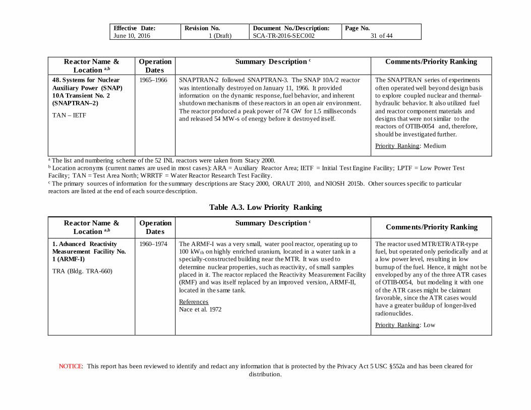
48. Systems for Nuclear Auxiliary Power (SNAP) 10A Transient No. 2 (SNAPTRAN–2)
TAN – IETF
1965–1966 SNAPTRAN-2 followed SNAPTRAN-3. The SNAP 10A/2 reactor was intentionally destroyed on January 11, 1966. It provided information on the dynamic response, fuel behavior, and inherent shutdown mechanisms of these reactors in an open air environment. The reactor produced a peak power of 74 GW for 1.5 milliseconds and released 54 MW-s of energy before it destroyed itself.
The SNAPTRAN series of experiments often operated well beyond design basis to explore coupled nuclear and thermal-hydraulic behavior. It also utilized fuel and reactor component materials and designs that were not similar to the reactors of OTIB-0054 and, therefore, should be investigated further.
Priority Ranking: Medium
a The list and numbering scheme of the 52 INL reactors were taken from Stacy 2000. b Location acronyms (current names are used in most cases): ARA = Auxiliary Reactor Area; IETF = Initial Test Engine Facility; LPTF = Low Power Test Facility; TAN = Test Area North; WRRTF = Water Reactor Research Test Facility. c The primary sources of information for the summary descriptions are Stacy 2000, ORAUT 2010, and NIOSH 2015b. Other sources specific to particular reactors are listed at the end of each source description.
Table A.3. Low Priority Ranking
Reactor Name & Location a,b
Operation Dates
Summary Description c Comments/Priority Ranking
1. Advanced Reactivity Measurement Facility No. 1 (ARMF-I)
TRA (Bldg. TRA-660)
1960–1974 The ARMF-I was a very small, water pool reactor, operating up to 100 kWth on highly enriched uranium, located in a water tank in a specially-constructed building near the MTR. It was used to determine nuclear properties, such as reactivity, of small samples placed in it. The reactor replaced the Reactivity Measurement Facility (RMF) and was itself replaced by an improved version, ARMF-II, located in the same tank.
References Nace et al. 1972
The reactor used MTR/ETR/ATR-type fuel, but operated only periodically and at a low power level, resulting in low burnup of the fuel. Hence, it might not be enveloped by any of the three ATR cases of OTIB-0054, but modeling it with one of the ATR cases might be claimant favorable, since the ATR cases would have a greater buildup of longer-lived radionuclides.
Priority Ranking: Low
Effective Date: June 10, 2016
Revision No. 1 (Draft)
Document No./Description: SCA-TR-2016-SEC002
Page No. 32 of 44
NOTICE: This report has been reviewed to identify and redact any information that is protected by the Privacy Act 5 USC §552a and has been cleared for distribution.
Reactor Name & Location a,b
Operation Dates
Summary Description c Comments/Priority Ranking
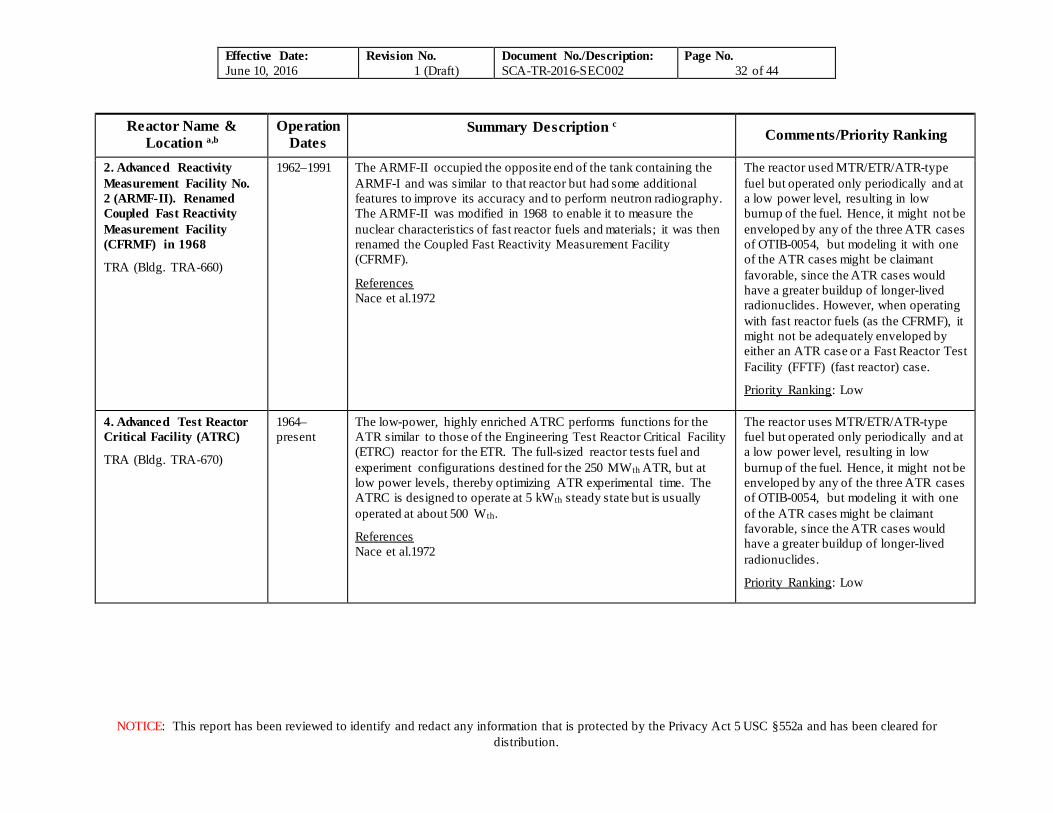
2. Advanced Reactivity Measurement Facility No. 2 (ARMF-II). Renamed Coupled Fast Reactivity Measurement Facility (CFRMF) in 1968
TRA (Bldg. TRA-660)
1962–1991 The ARMF-II occupied the opposite end of the tank containing the ARMF-I and was similar to that reactor but had some additional features to improve its accuracy and to perform neutron radiography. The ARMF-II was modified in 1968 to enable it to measure the nuclear characteristics of fast reactor fuels and materials; it was then renamed the Coupled Fast Reactivity Measurement Facility (CFRMF).
References Nace et al.1972
The reactor used MTR/ETR/ATR-type fuel but operated only periodically and at a low power level, resulting in low burnup of the fuel. Hence, it might not be enveloped by any of the three ATR cases of OTIB-0054, but modeling it with one of the ATR cases might be claimant favorable, since the ATR cases would have a greater buildup of longer-lived radionuclides. However, when operating with fast reactor fuels (as the CFRMF), it might not be adequately enveloped by either an ATR case or a Fast Reactor Test Facility (FFTF) (fast reactor) case.
Priority Ranking: Low
4. Advanced Test Reactor Critical Facility (ATRC)
TRA (Bldg. TRA-670)
1964–present
The low-power, highly enriched ATRC performs functions for the ATR similar to those of the Engineering Test Reactor Critical Facility (ETRC) reactor for the ETR. The full-sized reactor tests fuel and experiment configurations destined for the 250 MWth ATR, but at low power levels, thereby optimizing ATR experimental time. The ATRC is designed to operate at 5 kWth steady state but is usually operated at about 500 Wth.
References Nace et al.1972
The reactor uses MTR/ETR/ATR-type fuel but operated only periodically and at a low power level, resulting in low burnup of the fuel. Hence, it might not be enveloped by any of the three ATR cases of OTIB-0054, but modeling it with one of the ATR cases might be claimant favorable, since the ATR cases would have a greater buildup of longer-lived radionuclides.
Priority Ranking: Low

Effective Date: June 10, 2016
Revision No. 1 (Draft)
Document No./Description: SCA-TR-2016-SEC002
Page No. 33 of 44
NOTICE: This report has been reviewed to identify and redact any information that is protected by the Privacy Act 5 USC §552a and has been cleared for distribution.
Reactor Name & Location a,b
Operation Dates
Summary Description c Comments/Priority Ranking
12. Coupled Fast Reactivity Measurement Facility (CFRMF). Formerly named Advanced Reactivity Measurement Facility No. 2 (ARMF-II)
TRA (Bldg. TRA-660)
1968–1991 When the ARMF-II reactor was modified in 1968, it was given a new name, the CFRMF. A section of the core was modified to produce a region of high-energy neutron flux that was useful in comparing calculated and observed results. This tool provided physics information about the behavior of fast (i.e., unmoderated fission) neutrons. Physicists studied differential cross-sections and tested calculational methods. The CFRMF contributed to the development of fast neutron reactors.
The CFRMF operated only periodically and at a low power level, resulting in low burnup of the fuel. When running as a fast reactor, it might not be adequately enveloped by either an ATR case or a FFTF (fast reactor) case, but modeling it with one of the ATR cases might be claimant favorable.
Priority Ranking: Low
13. Critical Experiment Tank (CET)
TAN – WRRTF – LPTF
1958–1960 Three low-power reactors (less than 100 Wth) supported the Aircraft Nuclear Propulsion (ANP) program by testing various components and collecting nuclear physics data: the Critical Experiment Tank (CET), the Hot Critical Experiment (HOTCE), and the Shield Pool Test Facility (STPF) Reactor (SUSIE). They were located in the LPTF, which was part of the WRRTF of TAN.
The water-moderated, beryllium-reflected CET was a low-power reactor that was originally intended to simulate the Heat Transfer Reactor Experiment (HTRE)-1 and HTRE-2 reactors in the ANP program, and to perform critical experiments of HTRE fuel bundles. It was also used as a source of neutrons to calibrate neutron sensors.
It is not clear without a more in-depth investigation whether the CET would be adequately enveloped by any of the OTIB-0054 cases. However, the reactor was low power and operated for only a short period of time.
Priority Ranking: Low
Effective Date: June 10, 2016
Revision No. 1 (Draft)
Document No./Description: SCA-TR-2016-SEC002
Page No. 34 of 44
NOTICE: This report has been reviewed to identify and redact any information that is protected by the Privacy Act 5 USC §552a and has been cleared for distribution.
Reactor Name & Location a,b
Operation Dates
Summary Description c Comments/Priority Ranking
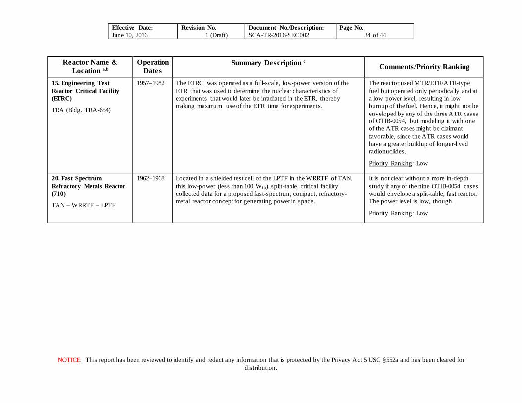
15. Engineering Test Reactor Critical Facility (ETRC)
TRA (Bldg. TRA-654)
1957–1982 The ETRC was operated as a full-scale, low-power version of the ETR that was used to determine the nuclear characteristics of experiments that would later be irradiated in the ETR, thereby making maximum use of the ETR time for experiments.
The reactor used MTR/ETR/ATR-type fuel but operated only periodically and at a low power level, resulting in low burnup of the fuel. Hence, it might not be enveloped by any of the three ATR cases of OTIB-0054, but modeling it with one of the ATR cases might be claimant favorable, since the ATR cases would have a greater buildup of longer-lived radionuclides.
Priority Ranking: Low
20. Fast Spectrum Refractory Metals Reactor (710)
TAN – WRRTF – LPTF
1962–1968 Located in a shielded test cell of the LPTF in the WRRTF of TAN, this low-power (less than 100 Wth), split-table, critical facility collected data for a proposed fast-spectrum, compact, refractory-metal reactor concept for generating power in space.
It is not clear without a more in-depth study if any of the nine OTIB-0054 cases would envelope a split-table, fast reactor. The power level is low, though.
Priority Ranking: Low
Effective Date: June 10, 2016
Revision No. 1 (Draft)
Document No./Description: SCA-TR-2016-SEC002
Page No. 35 of 44
NOTICE: This report has been reviewed to identify and redact any information that is protected by the Privacy Act 5 USC §552a and has been cleared for distribution.
Reactor Name & Location a,b
Operation Dates
Summary Description c Comments/Priority Ranking
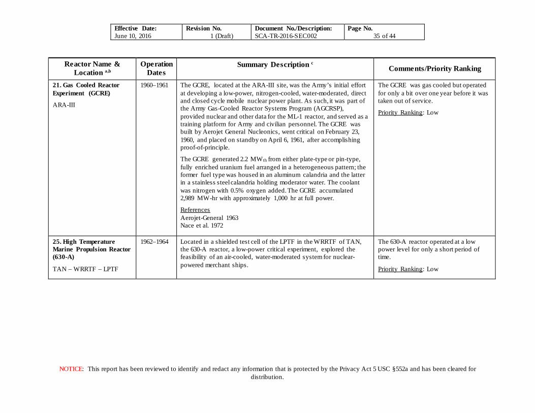
21. Gas Cooled Reactor Experiment (GCRE)
ARA-III
1960–1961 The GCRE, located at the ARA-III site, was the Army’s initial effort at developing a low-power, nitrogen-cooled, water-moderated, direct and closed cycle mobile nuclear power plant. As such, it was part of the Army Gas-Cooled Reactor Systems Program (AGCRSP), provided nuclear and other data for the ML-1 reactor, and served as a training platform for Army and civilian personnel. The GCRE was built by Aerojet General Nucleonics, went critical on February 23, 1960, and placed on standby on April 6, 1961, after accomplishing proof-of-principle.
The GCRE generated 2.2 MWth from either plate-type or pin-type, fully enriched uranium fuel arranged in a heterogeneous pattern; the former fuel type was housed in an aluminum calandria and the latter in a stainless steel calandria holding moderator water. The coolant was nitrogen with 0.5% oxygen added. The GCRE accumulated 2,989 MW-hr with approximately 1,000 hr at full power.
References Aerojet-General 1963 Nace et al. 1972
The GCRE was gas cooled but operated for only a bit over one year before it was taken out of service.
Priority Ranking: Low
25. High Temperature Marine Propulsion Reactor (630-A)
TAN – WRRTF – LPTF
1962–1964 Located in a shielded test cell of the LPTF in the WRRTF of TAN, the 630-A reactor, a low-power critical experiment, explored the feasibility of an air-cooled, water-moderated system for nuclear-powered merchant ships.
The 630-A reactor operated at a low power level for only a short period of time.
Priority Ranking: Low

Effective Date: June 10, 2016
Revision No. 1 (Draft)
Document No./Description: SCA-TR-2016-SEC002
Page No. 36 of 44
NOTICE: This report has been reviewed to identify and redact any information that is protected by the Privacy Act 5 USC §552a and has been cleared for distribution.
Reactor Name & Location a,b
Operation Dates
Summary Description c Comments/Priority Ranking
26. Hot Critical Experiment (HOTCE)
TAN – WRRTF – LPTF
1958–1961 Three low-power (less than 100 Wth) reactors supported the ANP program by testing various components and collecting nuclear physics data: the CET, the HOTCE, and the STPF Reactor (SUSIE). They were located in the LPTF, which was part of the WRRTF of TAN.
HOTCE was a low-power, high-temperature critical reactor experiment containing 50.4 kg of 93.2%-enriched UO2 in 1/8 inch-thick stainless steel wire. It had a hydrided zirconium reactor and a beryllium reflector. The experiments were intended to measure temperature coefficients in solid moderated reactors. HOTCE typically operated at a power level of 1 Wth for up to one to three hours, but could operate at 100 Wth for short periods.
It is not clear without a more in-depth investigation whether the CET would be adequately enveloped by any of the OTIB-0054 cases. However, the reactor was low power and operated for only a short period of time.
Priority Ranking: Low
34. Nuclear Effects Reactor (FRAN)
ARA-IV
1968–1970 FRAN was a small, prompt-burst reactor that could go super critical for a short time, producing a copious amount of fast neutron and gamma radiation inside its annular void, where samples would be placed. Expansion of its fuel assembly would quickly lower the reactivity, thereby controlling the excursion. The bare cylindrical assembly, which consisted of stacked, cylindrical fuel rings with an internal void for sample irradiation, was fueled with 93.5% enriched uranium and clad with nickel and cadmium. FRAN was used to test new detector systems and to provide heat transfer and nuclear physics information of materials subjected to intense fast-neutron bombardment. Power burst were self-limiting and produced very large, short-duration fast neutron bursts. About 180 bursts were produced over the lifetime of the facility, which was located in a specially-designed underground bunker.
FRAN was designed and built at the Lawrence Livermore National Laboratory (current name) and brought back there in 1970.
References Stillman and Mead 1965
FRAN appears to lie outside the reactors of OTIB-0054, but it was quite small and operated for only a short period of time.
Note: FRAN appears in Stacy 2000 and other literature that was examined, but not in the INL site profile.
Priority Ranking: Low
Effective Date: June 10, 2016
Revision No. 1 (Draft)
Document No./Description: SCA-TR-2016-SEC002
Page No. 37 of 44
NOTICE: This report has been reviewed to identify and redact any information that is protected by the Privacy Act 5 USC §552a and has been cleared for distribution.
Reactor Name & Location a,b
Operation Dates
Summary Description c Comments/Priority Ranking
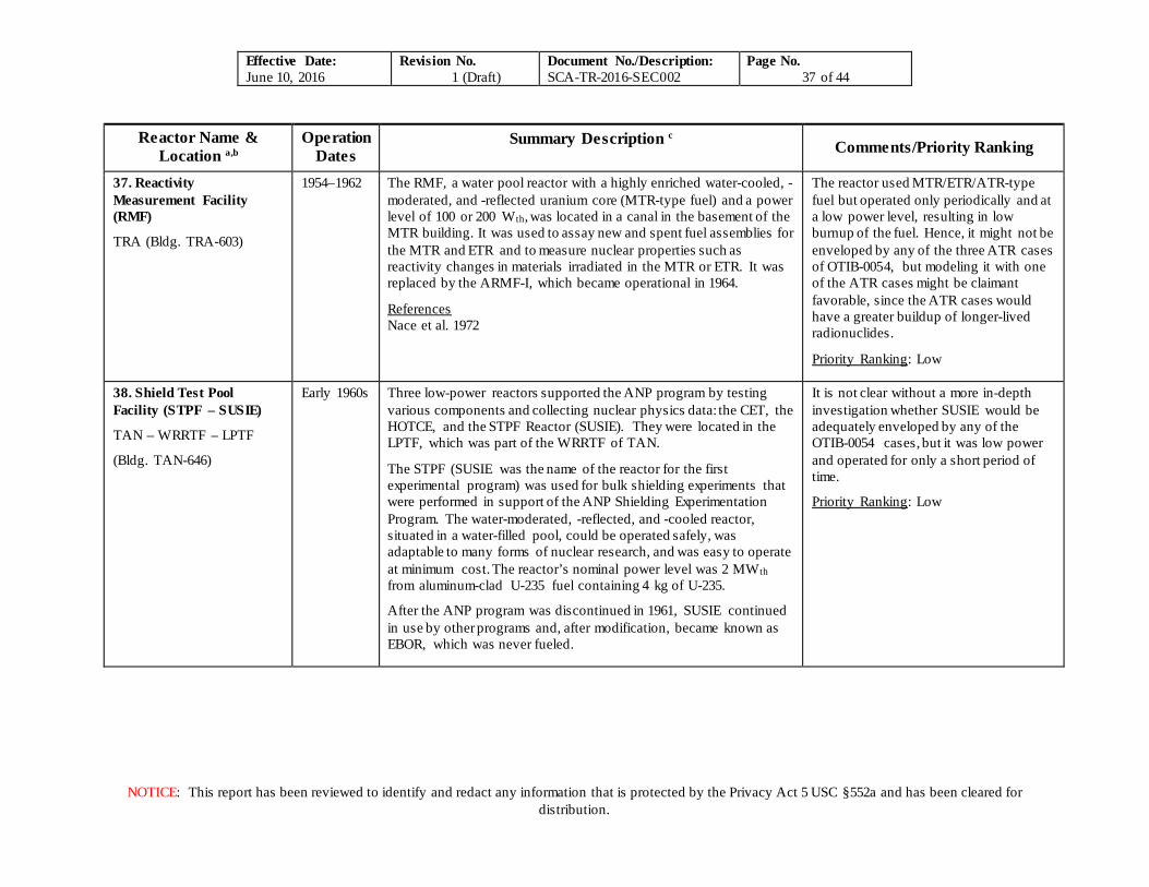
37. Reactivity Measurement Facility (RMF)
TRA (Bldg. TRA-603)
1954–1962 The RMF, a water pool reactor with a highly enriched water-cooled, -moderated, and -reflected uranium core (MTR-type fuel) and a power level of 100 or 200 Wth, was located in a canal in the basement of the MTR building. It was used to assay new and spent fuel assemblies for the MTR and ETR and to measure nuclear properties such as reactivity changes in materials irradiated in the MTR or ETR. It was replaced by the ARMF-I, which became operational in 1964.
References Nace et al. 1972
The reactor used MTR/ETR/ATR-type fuel but operated only periodically and at a low power level, resulting in low burnup of the fuel. Hence, it might not be enveloped by any of the three ATR cases of OTIB-0054, but modeling it with one of the ATR cases might be claimant favorable, since the ATR cases would have a greater buildup of longer-lived radionuclides.
Priority Ranking: Low
38. Shield Test Pool Facility (STPF – SUSIE)
TAN – WRRTF – LPTF
(Bldg. TAN-646)
Early 1960s Three low-power reactors supported the ANP program by testing various components and collecting nuclear physics data: the CET, the HOTCE, and the STPF Reactor (SUSIE). They were located in the LPTF, which was part of the WRRTF of TAN.
The STPF (SUSIE was the name of the reactor for the first experimental program) was used for bulk shielding experiments that were performed in support of the ANP Shielding Experimentation Program. The water-moderated, -reflected, and -cooled reactor, situated in a water-filled pool, could be operated safely, was adaptable to many forms of nuclear research, and was easy to operate at minimum cost. The reactor’s nominal power level was 2 MWth from aluminum-clad U-235 fuel containing 4 kg of U-235.
After the ANP program was discontinued in 1961, SUSIE continued in use by other programs and, after modification, became known as EBOR, which was never fueled.
It is not clear without a more in-depth investigation whether SUSIE would be adequately enveloped by any of the OTIB-0054 cases, but it was low power and operated for only a short period of time.
Priority Ranking: Low
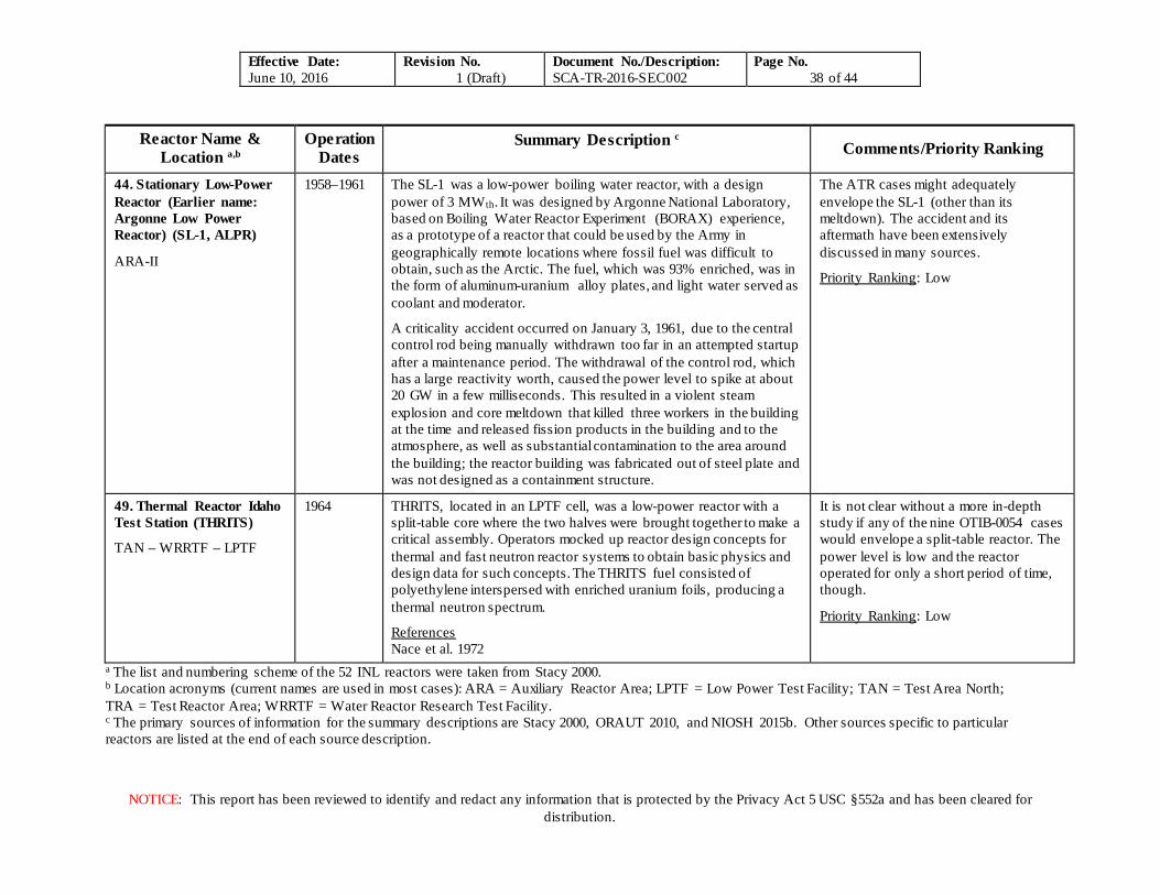
Effective Date: June 10, 2016
Revision No. 1 (Draft)
Document No./Description: SCA-TR-2016-SEC002
Page No. 38 of 44
NOTICE: This report has been reviewed to identify and redact any information that is protected by the Privacy Act 5 USC §552a and has been cleared for distribution.
Reactor Name & Location a,b
Operation Dates
Summary Description c Comments/Priority Ranking
44. Stationary Low-Power Reactor (Earlier name: Argonne Low Power Reactor) (SL-1, ALPR)
ARA-II
1958–1961 The SL-1 was a low-power boiling water reactor, with a design power of 3 MWth. It was designed by Argonne National Laboratory, based on Boiling Water Reactor Experiment (BORAX) experience, as a prototype of a reactor that could be used by the Army in geographically remote locations where fossil fuel was difficult to obtain, such as the Arctic. The fuel, which was 93% enriched, was in the form of aluminum-uranium alloy plates, and light water served as coolant and moderator.
A criticality accident occurred on January 3, 1961, due to the central control rod being manually withdrawn too far in an attempted startup after a maintenance period. The withdrawal of the control rod, which has a large reactivity worth, caused the power level to spike at about 20 GW in a few milliseconds. This resulted in a violent steam explosion and core meltdown that killed three workers in the building at the time and released fission products in the building and to the atmosphere, as well as substantial contamination to the area around the building; the reactor building was fabricated out of steel plate and was not designed as a containment structure.
The ATR cases might adequately envelope the SL-1 (other than its meltdown). The accident and its aftermath have been extensively discussed in many sources.
Priority Ranking: Low
49. Thermal Reactor Idaho Test Station (THRITS)
TAN – WRRTF – LPTF
1964 THRITS, located in an LPTF cell, was a low-power reactor with a split-table core where the two halves were brought together to make a critical assembly. Operators mocked up reactor design concepts for thermal and fast neutron reactor systems to obtain basic physics and design data for such concepts. The THRITS fuel consisted of polyethylene interspersed with enriched uranium foils, producing a thermal neutron spectrum.
References Nace et al. 1972
It is not clear without a more in-depth study if any of the nine OTIB-0054 cases would envelope a split-table reactor. The power level is low and the reactor operated for only a short period of time, though.
Priority Ranking: Low
a The list and numbering scheme of the 52 INL reactors were taken from Stacy 2000. b Location acronyms (current names are used in most cases): ARA = Auxiliary Reactor Area; LPTF = Low Power Test Facility; TAN = Test Area North; TRA = Test Reactor Area; WRRTF = Water Reactor Research Test Facility. c The primary sources of information for the summary descriptions are Stacy 2000, ORAUT 2010, and NIOSH 2015b. Other sources specific to particular reactors are listed at the end of each source description.
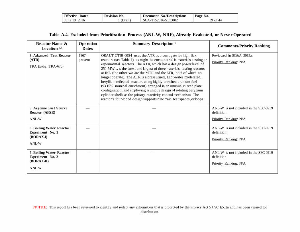
Effective Date: June 10, 2016
Revision No. 1 (Draft)
Document No./Description: SCA-TR-2016-SEC002
Page No. 39 of 44
NOTICE: This report has been reviewed to identify and redact any information that is protected by the Privacy Act 5 USC §552a and has been cleared for distribution.
Table A.4. Excluded from Prioritization Process (ANL-W, NRF), Already Evaluated, or Never Operated
Reactor Name & Location a,b
Operation Dates
Summary Description c Comments/Priority Ranking
3. Advanced Test Reactor (ATR)
TRA (Bldg. TRA-670)
1967–present
ORAUT-OTIB-0054 uses the ATR as a surrogate for high-flux reactors (see Table 1), as might be encountered in materials testing or experimental reactors. The ATR, which has a design power level of 250 MWth, is the latest and largest of three materials testing reactors at INL (the other two are the MTR and the ETR, both of which no longer operate). The ATR is a pressurized, light-water moderated, beryllium-reflected reactor, using highly enriched uranium fuel (93.15% nominal enrichment) arranged in an unusual curved plate configuration, and employing a unique design of rotating beryllium cylinder shells as the primary reactivity control mechanism. The reactor’s four-lobed design supports nine main test spaces, or loops.
Reviewed in SC&A 2015a.
Priority Ranking: N/A
5. Argonne Fast Source Reactor (AFSR)
ANL-W
— — ANL-W is not included in the SEC-0219 definition.
Priority Ranking: N/A
6. Boiling Water Reactor Experiment No. 1 (BORAX-I)
ANL-W
— — ANL-W is not included in the SEC-0219 definition.
Priority Ranking: N/A
7. Boiling Water Reactor Experiment No. 2 (BORAX-II)
ANL-W
— — ANL-W is not included in the SEC-0219 definition.
Priority Ranking: N/A
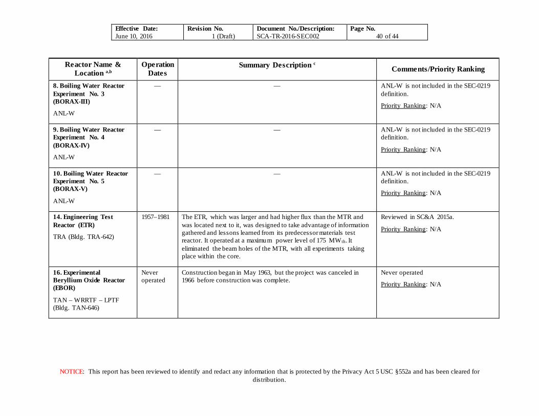
Effective Date: June 10, 2016
Revision No. 1 (Draft)
Document No./Description: SCA-TR-2016-SEC002
Page No. 40 of 44
NOTICE: This report has been reviewed to identify and redact any information that is protected by the Privacy Act 5 USC §552a and has been cleared for distribution.
Reactor Name & Location a,b
Operation Dates
Summary Description c Comments/Priority Ranking
8. Boiling Water Reactor Experiment No. 3 (BORAX-III)
ANL-W
— — ANL-W is not included in the SEC-0219 definition.
Priority Ranking: N/A
9. Boiling Water Reactor Experiment No. 4 (BORAX-IV)
ANL-W
— — ANL-W is not included in the SEC-0219 definition.
Priority Ranking: N/A
10. Boiling Water Reactor Experiment No. 5 (BORAX-V)
ANL-W
— — ANL-W is not included in the SEC-0219 definition.
Priority Ranking: N/A
14. Engineering Test Reactor (ETR)
TRA (Bldg. TRA-642)
1957–1981 The ETR, which was larger and had higher flux than the MTR and was located next to it, was designed to take advantage of information gathered and lessons learned from its predecessor materials test reactor. It operated at a maximum power level of 175 MWth. It eliminated the beam holes of the MTR, with all experiments taking place within the core.
Reviewed in SC&A 2015a.
Priority Ranking: N/A
16. Experimental Beryllium Oxide Reactor (EBOR)
TAN – WRRTF – LPTF (Bldg. TAN-646)
Never operated
Construction began in May 1963, but the project was canceled in 1966 before construction was complete.
Never operated
Priority Ranking: N/A
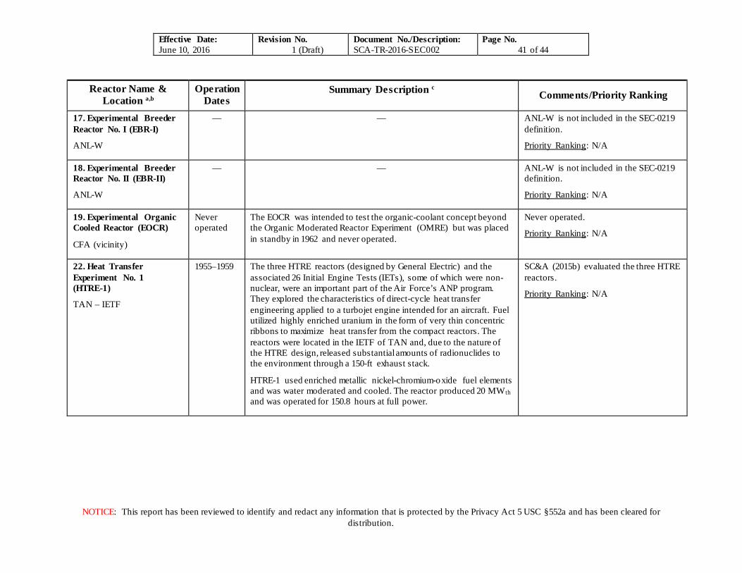
Effective Date: June 10, 2016
Revision No. 1 (Draft)
Document No./Description: SCA-TR-2016-SEC002
Page No. 41 of 44
NOTICE: This report has been reviewed to identify and redact any information that is protected by the Privacy Act 5 USC §552a and has been cleared for distribution.
Reactor Name & Location a,b
Operation Dates
Summary Description c Comments/Priority Ranking
17. Experimental Breeder Reactor No. I (EBR-I)
ANL-W
— — ANL-W is not included in the SEC-0219 definition.
Priority Ranking: N/A
18. Experimental Breeder Reactor No. II (EBR-II)
ANL-W
— — ANL-W is not included in the SEC-0219 definition.
Priority Ranking: N/A
19. Experimental Organic Cooled Reactor (EOCR)
CFA (vicinity)
Never operated
The EOCR was intended to test the organic-coolant concept beyond the Organic Moderated Reactor Experiment (OMRE) but was placed in standby in 1962 and never operated.
Never operated.
Priority Ranking: N/A
22. Heat Transfer Experiment No. 1 (HTRE-1)
TAN – IETF
1955–1959 The three HTRE reactors (designed by General Electric) and the associated 26 Initial Engine Tests (IETs), some of which were non-nuclear, were an important part of the Air Force’s ANP program. They explored the characteristics of direct-cycle heat transfer engineering applied to a turbojet engine intended for an aircraft. Fuel utilized highly enriched uranium in the form of very thin concentric ribbons to maximize heat transfer from the compact reactors. The reactors were located in the IETF of TAN and, due to the nature of the HTRE design, released substantial amounts of radionuclides to the environment through a 150-ft exhaust stack.
HTRE-1 used enriched metallic nickel-chromium-oxide fuel elements and was water moderated and cooled. The reactor produced 20 MWth and was operated for 150.8 hours at full power.
SC&A (2015b) evaluated the three HTRE reactors.
Priority Ranking: N/A
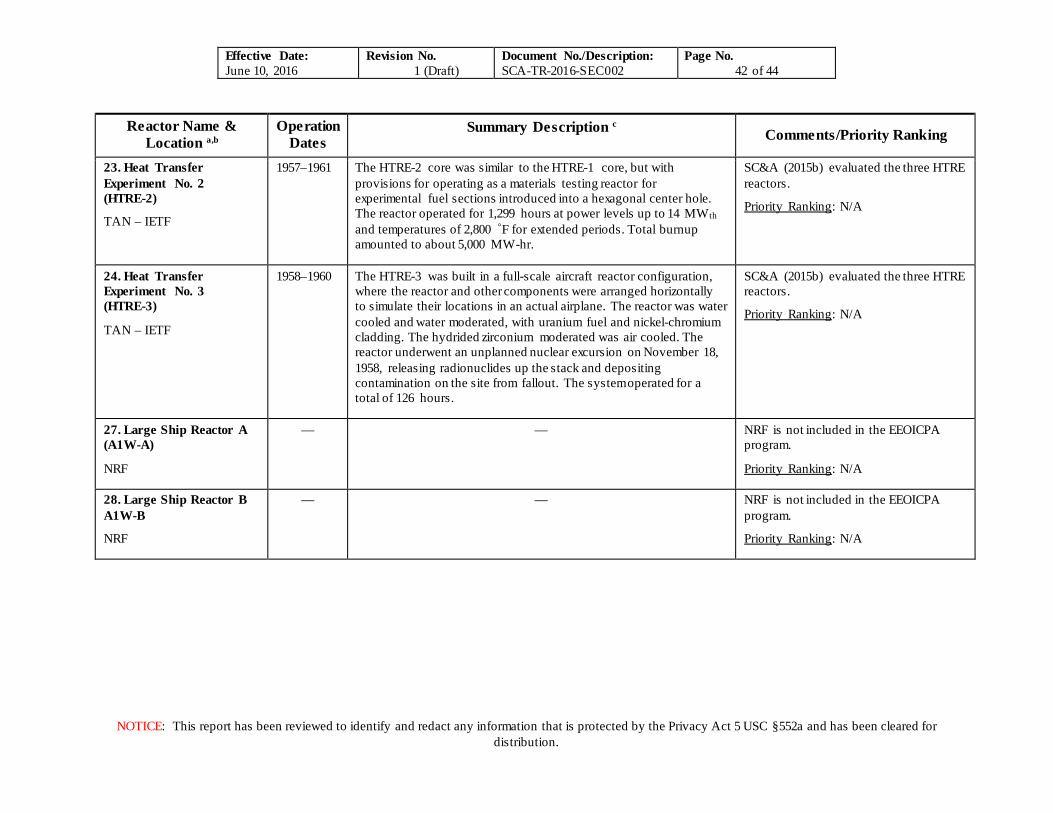
Effective Date: June 10, 2016
Revision No. 1 (Draft)
Document No./Description: SCA-TR-2016-SEC002
Page No. 42 of 44
NOTICE: This report has been reviewed to identify and redact any information that is protected by the Privacy Act 5 USC §552a and has been cleared for distribution.
Reactor Name & Location a,b
Operation Dates
Summary Description c Comments/Priority Ranking
23. Heat Transfer Experiment No. 2 (HTRE-2)
TAN – IETF
1957–1961 The HTRE-2 core was similar to the HTRE-1 core, but with provisions for operating as a materials testing reactor for experimental fuel sections introduced into a hexagonal center hole. The reactor operated for 1,299 hours at power levels up to 14 MWth and temperatures of 2,800 °F for extended periods. Total burnup amounted to about 5,000 MW-hr.
SC&A (2015b) evaluated the three HTRE reactors.
Priority Ranking: N/A
24. Heat Transfer Experiment No. 3 (HTRE-3)
TAN – IETF
1958–1960 The HTRE-3 was built in a full-scale aircraft reactor configuration, where the reactor and other components were arranged horizontally to simulate their locations in an actual airplane. The reactor was water cooled and water moderated, with uranium fuel and nickel-chromium cladding. The hydrided zirconium moderated was air cooled. The reactor underwent an unplanned nuclear excursion on November 18, 1958, releasing radionuclides up the stack and depositing contamination on the site from fallout. The system operated for a total of 126 hours.
SC&A (2015b) evaluated the three HTRE reactors.
Priority Ranking: N/A
27. Large Ship Reactor A (A1W-A)
NRF
— — NRF is not included in the EEOICPA program.
Priority Ranking: N/A
28. Large Ship Reactor B A1W-B
NRF
— — NRF is not included in the EEOICPA program.
Priority Ranking: N/A

Effective Date: June 10, 2016
Revision No. 1 (Draft)
Document No./Description: SCA-TR-2016-SEC002
Page No. 43 of 44
NOTICE: This report has been reviewed to identify and redact any information that is protected by the Privacy Act 5 USC §552a and has been cleared for distribution.
Reactor Name & Location a,b
Operation Dates
Summary Description c Comments/Priority Ranking
30. Materials Test Reactor (MTR)
TRA (Bldg. TRA-603)
1952–1970 The MTR was the first materials test reactor at INL (it was succeeded by the ETR and the currently operating ATR). It was cooled and moderated with light water and used Al-clad, curved plate, highly enriched uranium fuel most of the time. Beryllium, graphite, and light-water neutron reflectors surrounded the relatively small core. Experiments were conducted external to the core, utilizing neutron fluxes exiting through beam holes. Its maximum power level increase from 30 MWth to 40 MWth in 1955. In 1958, it became the first reactor to operate with a plutonium-239 (Pu-239) core at up to 30 MWth in a demonstration project.
Reviewed in SC&A 2015a.
Priority Ranking: N/A
32. Natural Circulation Reactor (S5G)
NRF
— — NRF is not included in the EEOICPA program.
Priority Ranking: N/A
33. Neutron Radiography Facility (NRAD)
ANL-W
— — ANL-W is not included in the SEC-0219 definition.
Priority Ranking: N/A
45. Submarine Thermal Reactor (S1W, STR). Also known as the Submarine Prototype Reactor
NRF
— — NRF is not included in the EEOICPA program.
Priority Ranking: N/A
50. Transient Reactor Test Facility (TREAT)
ANL-W
— — ANL-W is not included in the SEC-0219 definition.
Priority Ranking: N/A

Effective Date: June 10, 2016
Revision No. 1 (Draft)
Document No./Description: SCA-TR-2016-SEC002
Page No. 44 of 44
NOTICE: This report has been reviewed to identify and redact any information that is protected by the Privacy Act 5 USC §552a and has been cleared for distribution.
Reactor Name & Location a,b
Operation Dates
Summary Description c Comments/Priority Ranking
51. Zero Power Physics Reactor (Earlier name: Zero Power Plutonium Reactor) (ZPPR)
ANL-W
— — ANL-W is not included in the SEC-0219 definition.
Priority Ranking: N/A
52. Zero Power Reactor No. 3 (ZPR-III)
ANL-W
— — ANL-W is not included in the SEC-0219 definition.
Priority Ranking: N/A
a The list and numbering scheme of the 52 INL reactors were taken from Stacy 2000. b Location acronyms (current names are used in most cases): ANL;-W = Argonne National Laboratory-West; CFA = Central Facilities Area; IETF = Initial Test Engine Facility; LPTF = Low Power Test Facility; NRF = Naval Reactor Facility; TAN = Test Area North; TRA = Test Reactor Area; WRRTF = Water Reactor Research Test Facility. c The primary sources of information for the summary descriptions are Stacy 2000, ORAUT 2010, and NIOSH 2015b. Other sources specific to particular reactors are listed at the end of each source description.