emeraldtm ice digital key telephone system · equipment design or specifications. ... the maximum...
TRANSCRIPT

TMEmerald ICE
Digital Key
Telephone System
Hardware Installation Manual

The information contained in this document is proprietary and is subject to all relevant copyright, patent and other laws protecting intellectual property, as well as any specific
agreement protecting TADIRAN TELECOM, INC. (herein referred to as the “Manufacturer”) rights in the aforesaid information. Neither this document nor the information contained
herein may be published, reproduced or disclosed to third parties, in whole or in part, without the express, prior, written permission of the Manufacturer. In addition, any use of this
document or the information contained herein for any purposes other than those for which it was disclosed is strictly forbidden.
The Manufacturer reserves the right, without prior notice or liability, to make changes in equipment design or specifications.
Information supplied by the Manufacturer is believed to be accurate and reliable. However, no responsibility is assumed by the Manufacturer for the use there of nor for the rights of third
parties which may be affected in any way by the use thereof.
Any representation(s) in this document concerning performance of the Manufacturerʹs product(s) are for informational purposes only and are not warranties of future performance either express or implied. The Manufacturerʹs standard limited warranty, stated in its sales contract or order confirmation form, is the only warranty offered by the Manufacturer in
relation thereto.
This document may contain flaws, omissions or typesetting errors; no warranty is granted nor liability assumed in relation thereto unless specifically undertaken in the Manufacturerʹs sales
contract or order confirmation. Information contained herein is periodically updated and changes will be incorporated into subsequent editions. If you have encountered an error,
please notify the Manufacturer. All specifications are subject to change without prior notice.
© Copyright by TADIRAN TELECOM, INC., 2005. All rights reserved worldwide.

Record of RevisionsRevision Date of Issue Supercedes Major Changes - Brief Description
initial Release March 6, 2006 N/A


FEDERAL COMMUNICATIONS COMMISSION RULESPART 68 COMPLIANCE STATEMENT
This equipment complies with Part 68 of the FCC rules. On the left side of the interior card frame (Coral I‐S, Coral I, and Coral II systems); or inside the rear doors on the left side of the cabinet frame (Coral III cabinets) of this equipment is a label that contains, among other information, the FCC registration number and ringer equivalence number (REN) for this equipment. If requested, this information must be provided to the telephone company.
The REN is used to determine the quantity of devices which may be connected to the telephone line. Excessive REN’s on the telephone line may result in the devices not ringing in response to an incoming call. In most, but not all areas, the sum of the REN’s should not exceed five (5.0). To be certain of the number of devices that may be connected to the line, as determined by the total REN’s contact the telephone company to determine the maximum REN for the calling area.
An FCC compliant telephone cord and modular plug is provided with this equipment. This equipment is designed to be connected to the telephone network or premises wiring using a compatible modular jack which is Part 68 compliant.
This equipment cannot be used on telephone company‐provided coin service. Connection to Party Line Service is subject to state tariffs.
If this equipment causes harm to the telephone network, the telephone company will notify you in advance that temporary discontinuance of service may be required. If advance notice is not practical, the telephone company will notify the customer as soon as possible. Also, you will be advised of your right to file a complaint with the FCC if you believe it is necessary.
The telephone company may make changes in its facilities, equipment, operations, or procedures that could affect the operation of the equipment. If this happens, the telephone company will provide advance notice in order for you to make the necessary modifications in order to maintain uninterrupted service.
If trouble is experienced with this equipment, please Contact Tadiran Telecom at: (813) 523‐0000 for repair and/or warranty information. If the trouble is causing harm to the telephone network, the telephone company may request you remove the equipment from the network until the problem is resolved.
The following repairs can be done by the customer: No repairs allowed.
This equipment is hearing‐aid compatible.
It is recommended that the customer install an AC surge arrestor in the AC outlet to which this device is connected. This is to avoid damaging the equipment caused by local lightning strikes and other electrical surges.
This equipment is capable of providing user’s access to interstate providers of operator services through the use of equal access codes. Modifications by aggregators to alter these capabilities may be a violation of the telephone operator consumer services improvement act of 1990 and part 68 of the FCC Rules.

FEDERAL COMMUNICATIONS COMMISSIONRADIO FREQUENCY INTERFERENCE STATEMENT
The Coral system generates, uses, and can radiate radio energy; and, if not installed in strict accordance with this installation manual, may cause harmful interference to radio communications.
This equipment has been tested and found to comply with the limits for a Class A digital device, pursuant to Subpart J of Part 15 of FCC Rules, which are designed to provide reasonable protection against such interference when this equipment is operated in a commercial environment. Operation of this equipment in a residential area is likely to cause unacceptable interference to radio and TV reception, in which case the operator at his own expense will be required to take whatever measures may be necessary to correct the interference.
To ensure continued compliance with specified radio energy emissions limits of FCC Rules, the following precautions must be observed while installing and operating the equipment:
1. Install the equipment in strict accordance with the manufacturer’s instructions.
2. Verify that the power supply and associated A.C. powered equipment are connected to a properly grounded electrical supply, and that power cords, if used, are unmodified.
3. Verify that the system grounding, including Master Ground, D.C. power system, and equipment cabinets, is in accordance with the manufacturer’s instructions and connected to an approved earth ground source.
4. Always replace the factory‐supplied cover or keep the cabinet doors closed when not servicing the equipment.
5. Make no modification to the equipment that would affect its compliance with the specified limits of FCC Rules.
6. Maintain the equipment in a satisfactory state of repair.
7. Verify that emissions limiting devices, such as ferrite blocks and radio frequency interference modules, are properly installed and functional.
If necessary the operator should consult their Supplier, Tadiran Telecom,Inc. or an experienced radio/television engineer for additional suggestions. The following booklet prepared by the Federal Communications Commission may be of assistance: “How to Identify and Resolve Radio‐TV Interference Problems.” This booklet is available from the U.S. Government Printing Office, Washington, D.C. 20402, Stock No. 004‐000‐00345‐4.

TC
1 Introduction .................................................................................................... 1-1
2 System Design.................................................................................................. 2-1
2.1 Key Service Unit (KSU) . . . . . . . . . . . . . . . . . . . . . . . . . . . . . . . . . . . . . . . . . . . . . . . . . . . . . . .2-12.2 Power Supply . . . . . . . . . . . . . . . . . . . . . . . . . . . . . . . . . . . . . . . . . . . . . . . . . . . . . . . . . . . . .2-22.3 Battery Charger Board (Optional). . . . . . . . . . . . . . . . . . . . . . . . . . . . . . . . . . . . . . . . . . . . . . . .2-32.4 CCB (Common Control Board) . . . . . . . . . . . . . . . . . . . . . . . . . . . . . . . . . . . . . . . . . . . . . . . . . .2-42.5 610+2 (KSU3 Component) . . . . . . . . . . . . . . . . . . . . . . . . . . . . . . . . . . . . . . . . . . . . . . . . . . . . .2-62.6 Base Board . . . . . . . . . . . . . . . . . . . . . . . . . . . . . . . . . . . . . . . . . . . . . . . . . . . . . . . . . . . . . .2-82.7 4SLT Board (Analog Port Module-4 Circuits) . . . . . . . . . . . . . . . . . . . . . . . . . . . . . . . . . . . . . . . . .2-92.8 12EKT (Digital Port Module - 12 Circuits) . . . . . . . . . . . . . . . . . . . . . . . . . . . . . . . . . . . . . . . . . . 2-102.9 6CO Board (Central Office Module - 6 Circuits) . . . . . . . . . . . . . . . . . . . . . . . . . . . . . . . . . . . . . . 2-112.10 Modem Module . . . . . . . . . . . . . . . . . . . . . . . . . . . . . . . . . . . . . . . . . . . . . . . . . . . . . . . . . . 2-122.11 4VAA Board (4-Port Voice Automated Attendant) . . . . . . . . . . . . . . . . . . . . . . . . . . . . . . . . . . . . 2-132.12 T1/PRI Card . . . . . . . . . . . . . . . . . . . . . . . . . . . . . . . . . . . . . . . . . . . . . . . . . . . . . . . . . . . . 2-142.13 Battery Charger . . . . . . . . . . . . . . . . . . . . . . . . . . . . . . . . . . . . . . . . . . . . . . . . . . . . . . . . . 2-162.14 Deluxe Model Telephone . . . . . . . . . . . . . . . . . . . . . . . . . . . . . . . . . . . . . . . . . . . . . . . . . . . . 2-172.15 Standard Model Telephone . . . . . . . . . . . . . . . . . . . . . . . . . . . . . . . . . . . . . . . . . . . . . . . . . . 2-192.16 DSS (Direct Station Selection Terminal) . . . . . . . . . . . . . . . . . . . . . . . . . . . . . . . . . . . . . . . . . . 2-202.17 Expansion Boards . . . . . . . . . . . . . . . . . . . . . . . . . . . . . . . . . . . . . . . . . . . . . . . . . . . . . . . . 2-212.18 System Limits/Capacities . . . . . . . . . . . . . . . . . . . . . . . . . . . . . . . . . . . . . . . . . . . . . . . . . . . 2-222.19 Configuration Flexibility . . . . . . . . . . . . . . . . . . . . . . . . . . . . . . . . . . . . . . . . . . . . . . . . . . . . 2-282.20 Power Consumption Table . . . . . . . . . . . . . . . . . . . . . . . . . . . . . . . . . . . . . . . . . . . . . . . . . . . 2-33
3 Installation . . . . . . . . . . . . . . . . . . . . . . . . . . . . . . . . . . . . . . . . . . . . . . . . . . . . . . . . 3-1
3.1 Installation Outline . . . . . . . . . . . . . . . . . . . . . . . . . . . . . . . . . . . . . . . . . . . . . . . . . . . . . . . . .3-13.2 Site Planning . . . . . . . . . . . . . . . . . . . . . . . . . . . . . . . . . . . . . . . . . . . . . . . . . . . . . . . . . . . . .3-3
4 Door Phone Installation . . . . . . . . . . . . . . . . . . . . . . . . . . . . . . . . . . . . . . . . . . . . . . . 4-1
4.1 General . . . . . . . . . . . . . . . . . . . . . . . . . . . . . . . . . . . . . . . . . . . . . . . . . . . . . . . . . . . . . . .4-14.2 Hardware Installation . . . . . . . . . . . . . . . . . . . . . . . . . . . . . . . . . . . . . . . . . . . . . . . . . . . . . . .4-24.3 Programming . . . . . . . . . . . . . . . . . . . . . . . . . . . . . . . . . . . . . . . . . . . . . . . . . . . . . . . . . . . . .4-6
5 RMP Setup . . . . . . . . . . . . . . . . . . . . . . . . . . . . . . . . . . . . . . . . . . . . . . . . . . . . . . . . 5-1
5.1 General . . . . . . . . . . . . . . . . . . . . . . . . . . . . . . . . . . . . . . . . . . . . . . . . . . . . . . . . . . . . . . .5-15.2 Using the RMP Setup Wizard . . . . . . . . . . . . . . . . . . . . . . . . . . . . . . . . . . . . . . . . . . . . . . . . . . .5-4
6 System Initialization . . . . . . . . . . . . . . . . . . . . . . . . . . . . . . . . . . . . . . . . . . . . . . . . . 6-1
7 T1/PRI Card Installation and Setup ........................................................................ 7-1
7.1 Description . . . . . . . . . . . . . . . . . . . . . . . . . . . . . . . . . . . . . . . . . . . . . . . . . . . . . . . . . . . . . .7-17.2 Installation . . . . . . . . . . . . . . . . . . . . . . . . . . . . . . . . . . . . . . . . . . . . . . . . . . . . . . . . . . . . . .7-47.1 RMP Setup . . . . . . . . . . . . . . . . . . . . . . . . . . . . . . . . . . . . . . . . . . . . . . . . . . . . . . . . . . . . . . .7-67.2 Deluxe Telephone Setup. . . . . . . . . . . . . . . . . . . . . . . . . . . . . . . . . . . . . . . . . . . . . . . . . . . . . 7-13
Emerald ICE Feature Programming Manual i


1
IntroductionIntroduction
1
The Tadiran Emerald Integrated Communication Exchange, (ICE) is a versatile, Digital Hybrid Key Telephone System that includes many advanced features. It is designed to meet the telecommunications needs of small to medium business offices.
The Emerald ICE is a fully digital hybrid key telephone system. Utilizing “Loop Start” central office (TELCO) line interfaces in conjunction with analog and digital extension ports, it provides office communications and connectivity to the Public Switched Telephone Network (PSTN).
The Emerald ICE offers a plethora of office productivity features and telephone enhancing features that include Caller Identification (required Telephone Company subscription) in the standard package. Unlike most systems that support Caller ID, the Emerald ICE supports Caller ID to Emerald ICE proprietary digital extensions and to third‐party, Caller ID capable analog devices (cordless telephones, etc.)
In addition to many standard features, several optional features are offered to further enhance office communications. These built‐in voice processing integration packages are:
• Automated Attendant • Both Flash and Hard Drive Based Voicemail/Auto Attendant
The Emerald ICE platform allows the application of these voice processing platforms without loss of valuable system port resources.
The Emerald ICE is comprised of an application‐configured, expandable Key Service Unit or KSU platform. When used with the full‐featured Deluxe Telephone and its display, it provides access to all system functions.
The Emerald ICE system architecture provides an expandable interface for digital port growth and analog port growth. The basic configuration supports both device types. (Analog ports might be used for plain old telephones, fax machines, modems, etc.)
Emerald ICE Installation & Hardware Reference Manual 1-1

Introduction
1
An illustration of the ICE cabinet and 2 Key Telephone Sets are shown below in Figure 1.
Figure 1-1 ICE Digital Hybrid Key Telephone System
The Emerald ICE incorporates state‐of‐the‐art digital technology for voice switching and call processing utilizing Pulse Code Modulation and Time Division Multiplexing (PCM/TDM).
Emerald ICE KSU Emerald ICE Deluxe Model Telephone
Emerald ICE Standard Model Telephone
1-2 Emerald ICE Installation & Hardware Reference Manual

Introduction
1
The Emerald ICE is a non‐blocking switch featuring no degradation of voice signals. The system utilizes a 16‐bit, 20 MHz main microprocessor and peripheral device (extensions and CO lines) processors in a distributed processing configuration. Memory consists of 640K bytes of ROM and 384K bytes of RAM.
The Emerald ICE is shipped as follows:
• 1‐KSU with the following: ‐Ten (10) digital extension ports.
‐Two (2) analog device ports.
‐Six (6) CID ready CO Line ports.
‐Two music source enters (can be assigned as desired to CO lines for hold music/messages.
‐One power failure port (CO Line 1).
‐One control contact (LBC, Gate, External Page Control).
‐One external paging equipment interface.
‐Two serial ports.
‐PC‐RMP Programming Interface.
‐SMDR (Station Message Detailed Recording).
Emerald ICE Installation & Hardware Reference Manual 1-3

Introduction
1
About this Manual
The Emerald ICE Hardware Installation Manual is divided into the following sections:
• Section 1 ‐ Introduction ‐ this section provides a general description of the Emerald ICE system as well as a description of the manual contents, associ‐ated documentation, and a listing of the document conventions.
• Section 2 ‐ System Design ‐ This section provides descriptions of the individ‐ual components of the Emerald ICE system.
• Section 3‐ Installation ‐ This section provides instructions for the installa‐tion of the KSU cabinets and pin out information. Includes Door Phone Installation procedures.
• Section 4 ‐ RMP Setup ‐ This section provides instructions for the installation and setup of the Emerald ICE Remote Maintenance and Programming applica‐tion.
• Section 5 ‐ System Initialization ‐ This section provides Deluxe and RMP programming instructions for the initilization of a new or reconfigured Emerald ICE KSU.
• Section 6 ‐ T1/PRI Installation & Setup ‐ This section provides descriptions of the installation and setup of the Emerald ICE T1/PRI Card.
1-4 Emerald ICE Installation & Hardware Reference Manual

Introduction
1
Document Conventions
The following conventions are used throughout this manual.
Table 1-1 Conventions
Convention Description
Normal Used in body text throughout this manual.
Normal, Italic Used in referencing sections, telephone features and voice recordings or prompts.
Bold, Italic Used in describing the fields in RMP screens and other form names or items.
Normal, Bold Used to describe filenames, device names and specific areas of RMP menus.
Press Means to press a specific key. (e.g. press ESC means to press and release the Escape key.)
Enter Means to type or push a button on the telephone keypad.
123 (Telephone Keys)
Indicates the keystrokes that are required to be entered on a telephone.
DISPLAY FONT Indicates a display on a Deluxe Model Telephone.
Emerald ICE Installation & Hardware Reference Manual 1-5

Introduction
1
Related Documents
The following documents should be used in conjunction with this manual:
• Emerald ICE Programming Manual• Emerald ICE Deluxe Model Telephone User Guide • Emerald ICE Standard Model Telephone User Guide • Emerald ICE Flash Voicemail Installation & Maintenance Manual • Emerald ICE HD Voicemail Installation & Maintenance Manual
1-6 Emerald ICE Installation & Hardware Reference Manual

2
System DesignSystem Design
2
The Emerald ICE Key Service Unit (KSU) is designed as a modularized, flat‐pack. Two KSU’s (KSU3 and KSU4) may be equipped to attain the total system capacity of 24 CO lines, 58 Extensions (46 digital and 18 analog) and 8 Voice Processing Channels. Each KSU is designed to be mounted on the wall and is shipped with a wall mounting template. The compact KSU weighs less than 20 pounds and is UL Listed.
If using 2 KSU’s, the first KSU, or KSU3 is factory equipped with one 610+2 Board, one CCB (Common Control Board). The second KSU or KSU4 is factory equipped with one Base Board module. Each KSU is a self‐contained cabinet containing an internal power supply for either 117vac or 230vac operation. At the time of shipping it is set for 117vac operation. From the exterior, with covers in place, KSU3 and KSU4 look identical, however, KSU3 contains the Common Control Board(CCB).
Figure 2-1 Emerald ICE KSU
2.1 Key Service Unit (KSU)
Emerald ICE Installation & Hardware Reference Manual 2-1

System Design
2
h
The power supply circuitry of the Emerald ICE incorporates a linear design AC transformer with a choice of enter voltage taps. The transformer primary windings are shipped wired for 117vac applications. A factory provided switch alternates between 230vac and 117vac applications. The output voltage is delivered to the 610+2 Board(in KSU3, Base Board in KSU4) for voltage regulation. All system operation and logic voltages are produced at these boards.
Two fuses are provided on the power supply board; one for ac enter over‐voltage protection and one for DC output over‐current protection. A main power switch is accessible on the side of each KSU. In the event battery backup operation is desired the KSU power cord can be connected with an external (ancillary) UPS (Uninterruptible Power Supply). It is the responsibility of the installer to match the battery requirements/UPS requirement to the specific needs of the equipment owner.
Figure 2-2 Power Supply
2.2 Power Supply
115V/230V Switch
KSU
2 Fuses
Main Power Switc(Side of Cabinet)
2-2 Emerald ICE Installation & Hardware Reference Manual

System Design
2
An optional battery charger card is available for connection with the power supply. This card is mounted on the power supply voltage regulator using 3 supplied standoffs. It provides a third‐party 24 volt, lead‐acid battery with .4 amps of constant current.
Relays on the battery charger card detect voltages over 24 volts to deactivate charging, while activating charging for voltages less than 24 volts.
Figure 2-3 Battery Charger
2.3 Battery Charger Board (Optional)
To Battery
To Power Supply
Manual Shutoff
Emerald ICE Installation & Hardware Reference Manual 2-3

System Design
2
The CCB module is equipped standard in KSU3. This board contains all circuitry required to control the fully equipped Emerald ICE. All digital voice switching and call processing data switching is accomplished via the CCB.
The CCB has one ribbon cable connector for connection to the KSU3 610+2 board and five (5) connector sockets for connection of the system built‐in modem, voice processor and 2nd Cabinet (KSU4). Since the CCB comes installed inside of KSU3 the CCB ribbon cable is already in place and connected to the KSU3‐610+2. Assuming the orientation of the KSU3 cabinet is installed on the wall; the two horizontal connector sockets in the lower left corner of the CCB are for the Modem Module. The connector socket labeled “2nd Cabinet” is for connection to the KSU4‐Base Board if that expansion is required. The remaining two connector sockets on the CCB, one at the left side, the other at the right side are for the voice processor solution. (The voice processor solution can be any of three possible choices; 4VAA, Flash Voicemail or HD Voicemail.)
Figure 2-4 CCB Board
2.4 CCB (Common Control Board)
2-4 Emerald ICE Installation & Hardware Reference Manual

System Design
2
The CCB also provides the following standard connectors:
• Music Channel 1 ‐ On Hold/Background Music Interface• Music Channel 2 ‐ On Hold/Background Music Interface• Control Contact (Loud Bell or External Page Relay)• External Paging Equipment Interface• RMP Serial Port ‐ for on‐site database programming• SMDR Serial Port ‐ for connection to ancillary SMDR/Call Accounting equip‐
mentThe CCB has two Option Strap jumpers one for database start‐up (J7) and one for Music Channel One source (internal/external) selection (JP81).
• JP7 Cold Start/Normal : JP7 is used to force load database default factory settings. This jumper will normally never require operation after the initial power up sequence is completed. However should the need arise to return the site database to the factory settings this jumper is used to accomplish the task.
• JP81 Internal/External: J81 is used to select the Music Channel 1 source. The Emerald ICE provides a synthesized music source for music on hold in appli‐cations where no music source is available. The synthesized tune is repeated. JP81 is in the “External” position when it ships from the factory.
The CCB is equipped with a Heart‐beat LED that indicates processing activity on the PCB. (The 610+2 peripheral processor is operating when the Heartbeat LED is flashing.) The KSU3 operation LED (located next to the power switch) is tied to the CCB Heartbeat LED. Therefore, when the LED next to the power switch is flashing, the CCB is active..
Emerald ICE Installation & Hardware Reference Manual 2-5

System Design
2
The 610+2 is the large circuit board that is packaged inside of KSU3. It 610+2 provides interface for up to 6 loop‐start CO Lines, 10 Digital Extension Ports and 2 analog ports. Additionally the 610+2 regulates the 24 volt DC power from the source to produce all required logic voltages and operations voltages. There is also a Power Failure Port located on the 610+2 that is connected to the first CO Line circuit. Whenever power fails this port becomes active with dial tone from the CO line connected to the first CO line port.
Figure 2-5 610+2 Board
Each CO line circuit on the 610+2 board incorporates over‐voltage protection, ring detector, loop detector, loop/pulse‐dial relay, current sink circuit, coupling/isolation transformer (impedance 600:600), hybrid circuit, CODEC & filter, polarity guard circuit and Radio Frequency noise filter.
The sixth CO Line port is equipped with CNG Fax Tone Detection circuitry. If FAX tone is detected, the call is routed to the analog port designated as the destination for fax calls.
Each digital port (connects to Deluxe & Standard Telephones and DSS Consoles) is comprised of a proprietary octal ASIC (Application Specific Integrated Circuit) transceiver. There are three data channels in operation at each digital port via the octal transceiver. One channel is used for call processing control of digital terminal
2.5 610+2 (KSU3 Component)
2-6 Emerald ICE Installation & Hardware Reference Manual

System Design
2
functions/operations and two channels are used for the digital voice channel requirements.
Each digital station interface is protected against circuit wiring shorts by an over‐current protection Polyswitch. The digital station circuit requires only one cable pair to operate and is not polarity sensitive.
Physical connection of digital extensions, power failure telephones and CO lines to the 610+2 board is made through a 25 pair amphenol connector to be terminated on the MDF. (Main Distribution Frame)
Emerald ICE Installation & Hardware Reference Manual 2-7

System Design
2
The Base Board is unique to KSU4. It provides connecitivity with peripheral boards. Additionally the Base Board regulates the 24 volt DC power from the source to produce all required logic voltages and operations voltages.
The KSU4 operation LED (located next to the power switch) is tied to the CCB (KSU3) LED. Therefore, when the LED next to the power switch is flashing, the CCB (KSU3) is active.
A long shielded cable is used to connect KSU4 to the CCCB inside of KSU3.
Each digital station interface is protected against circuit wiring shorts by an over‐current protection Polyswitch. The digital station circuit requires only one cable pair to operate and is not polarity sensitive.
Figure 2-6 Base Board
2.6 Base Board
2-8 Emerald ICE Installation & Hardware Reference Manual

System Design
2
The 4SLT Board provides four separate analog device ports. This allows the Emerald ICE to support auxiliary office equipment found on the business premises such as fax machines, PC/Mac modems and analog telephones (single line telephones). The 4SLT Board generates ‐30VDC and 20‐25Hz, 50V square wave ringing for operation.
The 4SLT Board is equipped with a Heartbeat LED that indicates processing activity on the PCB. (The 4SLT Board peripheral processor is operating when the Heartbeat LED is flashing.)
The 4SLT Board provides DTMF receivers for each analog port. Ancillary analog devices connected to 4SLT analog ports must generate DTMF signaling. (Pulse dial (rotary‐dial) telephones/equipment are not supported.) All connections are via RJ‐11 connectors along the top edge of the module.
Up to 2‐ 4SLT Boards may be installed on 610+2 Board and up to 2 in the Expansion Cabinet.
Figure 2-7 4SLT Board
2.7 4SLT Board (Analog Port Module-4 Circuits)
Emerald ICE Installation & Hardware Reference Manual 2-9

System Design
2
The 12EKT module expands the Emerald ICE system capacity of digital ports Deluxe & Standard Telephones and DSS Consoles. Each digital port is comprised of a proprietary octal ASIC (Application Specific Integrated Circuit) transceiver. There are three data channels in operation at each digital port via the octal transceiver. One channel is used for call processing control of digital terminal functions/operations and two channels are used for the digital voice channel requirements. The 12EKT is controlled directly from the 610+2 Board/Base Board.
Each digital station interface is protected against circuit wiring shorts by an over‐current protection Polyswitch. The digital station circuit requires only one cable pair to operate and is not polarity sensitive.
Physical connection of digital port terminals (Deluxe & Standard Telephone and DSS) to the 12EKT module is made through a 25‐pair amphenol connector along the top edge of the module.
1 Additional 12EKT module can be added to KSU3 and 2 in KSU4.
Figure 2-8 12EKT Card
2.8 12EKT (Digital Port Module - 12 Circuits)
2-10 Emerald ICE Installation & Hardware Reference Manual

System Design
2
The 6CO Board is installed in the dedicated position of the 610+2 Board/Base Board. The 6CO interfaces 6 loopstart CO (Central Office [Telephone Company]) lines. One 6CO Board is installed in KSU3. An additional 6CO Board can be added for a total of 12 loopstart CO lines. Two 6CO Boards may be installed in KSU4. Therefore, the Emerald ICE system CO line capacity may be expanded to interface 24 total loopstart CO lines.
The 6CO module is shipped with four (4) mounting stand‐offs used to install the board into the KSU3 or KSU4.
Each CO line circuit incorporates over‐voltage protection, ring detector, loop detector, loop/pulse‐dial relay, current sink circuit, coupling/isolation transformer (impedance 600:600), hybrid circuit, CODEC & filter, polarity guard circuit and Radio Frequency noise filter.
The sixth CO Line port is equipped with CNG Fax Tone Detection circuitry. When programmed as a “FAX” line, this circuit will automatically engage the FAX Tone detector. If FAX tone is detected, the call is routed to the analog port designated as the destination for fax calls.
Figure 2-9 6CO Board
2.9 6CO Board (Central Office Module - 6 Circuits)
Emerald ICE Installation & Hardware Reference Manual 2-11

System Design
2
The Modem Module is a self‐contained integrated modem unit that is installed at J5 and J6 in the lower left corner of the CCB. The integrated Modem Module allows the servicing Telephone Company to access the telephone system programming and remote maintenance utilities from an off‐site location (password verification required).
When installed, the servicing technician uses the RMP and a modem (in the PC) to place a call to the site where the Emerald ICE is installed. If one of the voice processing systems are installed, routing to the modem extension is automated. Otherwise the person who answered this data call must transfer the call to Extension 400 (Default). Once the modems have established the data connection, RMP may be used to perform all servicing operations.
Figure 2-10 Modem Module
The only configurable parameter in the Modem Module is the Baud Rate. Baud rate can be configured to 1200 or 2400 by using the RMP or the Deluxe Telephone set.
2.10 Modem Module
2-12 Emerald ICE Installation & Hardware Reference Manual

System Design
2
The Automated Attendant Module is a self contained integrated module that adds automatic answering of selected CO lines and a single‐level menu for greeting callers and routing them to Emerald ICE system destinations. The 4VAA is a low cost voice processing system that can handle all call traffic or act as a backup to the primary answering system attendant. It should be used as an alternative to the HD Voicemail or Flash Voicemail systems.
The 4VAA is installed at J3 and J4 of the CCB.
The 4VAA provides 10 greetings for the various modes of system/action operation. They are: Day Greeting, Alt Greeting, Night Greeting, Waiting Message, Invalid Message, Busy Message, No Answer Message, Goodbye Message, Inquiry Message and Temporary Message.
Figure 2-11 4VAA Board
2.11 4VAA Board (4-Port Voice Automated Attendant)
Emerald ICE Installation & Hardware Reference Manual 2-13

System Design
2
The T1 PRI card is installed in the designated slot on the Base Board in the Emerald ICE KSU4.
Figure 2-12 T1/PRI Card)
The card provides 23 channels.
The T1/PRI card is connected with a network via RJ‐45 or DB‐15 cables.
An on‐board crystal and can be set as master or slave to synchronize with the PSTN, depending upon the networking requirement.
A 15‐pin‐backplane interface covering the following portions:
• Power feeding: 5 VDCPCM highway: The system will provide an 8KHz frame signal for the T1/PRI card’s synchronization.
• Control Data Interface: It is compatible with SPI (Serial Peripheral Interface) bus timing.
For an outgoing call, the trunk group access code is dialed, (e.g. “9”) or individual trunk line lines (buttons) can be selected to seize an idle trunk. If a trunk group consists of an analog trunk and T1 trunk lines, access to the trunk group will be assigned with an idle trunk line in accordance with the programmed hunting methods such as SEQF (sequential from the first), SEQL (sequential from the last) or Random. The hunting sequence is based on the physical port number assigned to the individual trunk, either analog or digital.
An incoming call is treated as a normal analog trunk call and will ring the programmed answering extensions for notification. Calling party numbers will be displayed when received.
2.12 T1/PRI Card
2-14 Emerald ICE Installation & Hardware Reference Manual

System Design
2
Features
• CLIP/CLIR: Programmable to be enabled or disabled per system. The user is allowed to program corresponding feature access codes into feature keys indi‐cating programming status. Upon initiating outgoing ISDN trunk line call, the calling extension’s number will be sent out if CLIP is enabled.
• COLP/COLR: Programmable to be enabled or disabled per system. The user is allowed to program corresponding feature access codes into feature keys indi‐cating programming status. Upon answering an incoming ISDN trunk line call, the answering extension’s number will be sent out if COLP is enabled.
• DDI Service: Programmable to be enabled or disabled for each PRI port. When an incoming ISDN trunk line call is answered, the DDI number will be received by the system and checked against a DDI translation table. If one programming entry is matched with the received DDI number, the system will ring the corre‐sponding extension or hunt group number. If there is no match, the call will ring the operator directly.
• ßDDI Translation Table: This table is used to translate the received DDI number into the desired destination number, which can be either an extension number or a hunt group number. The length of the DDI number can be programmable, and can be up to a 12‐digit in maximum. The total number of programming entries in the table is 100 in maximum. If CLIP and COLP are enabled, if there is a pro‐gramming entry matched with the calling extension or answering extension’s number, the corresponding designated DDI number will be sent out instead.
• Auditing: The monitors the PRI port in order to keep track of its real time oper‐ating status. The operating status may be one of the following two conditions: failure to call setup or no connection. Through periodical monitoring, the latest operating status can be kept, either from normal to failure, or vice versus. When the PRI port is detected as “failure”, the system blocks the interface and gives a warning message upon access by the extension.
LED Indicators
The T1 Card has 9 LEDs which indicate of T1 trunk alarms, in‐use status, and synchronous clock enable status as shown Page 6-9, T1 Setup.
Refer to Page 6-1, T1/PRI Card Installation and Setup for additional installation and setup instructions.
Emerald ICE Installation & Hardware Reference Manual 2-15

System Design
2
The Battery Charger is an optional board in the Emerald ICE system. It is connected to the AC Power Supply Board via a 3‐pin connector and mounted on the Power Supply Board with 3 standoffs.
The Battery Charger can charge a 24v Lead‐Acid battery with .4 amp constant current and 26.4v nominal voltage. If the battery voltage is over 24 volts, a relay will activate turning the system off. If the battery voltage is under 24 volts the same relay turns the system on.
The battery is a third‐party item that can be purchased separately.
Figure 2-12 Battery Charger Module
2.13 Battery Charger
2-16 Emerald ICE Installation & Hardware Reference Manual

System Design
2
The Emerald ICE has one model digital telephone. The Deluxe Telephone is equipped with a half‐duplex speakerphone for hands‐free conversations and has a two‐row by sixteen column (32‐character), dot‐matrix, Super Twist, Liquid Crystal Display (LCD). Directly under the LCD are three Interactive Buttons to enhance system features operation. During the various features operations these Interactive Buttons take‐on functions to aid in feature use.
The Super Twist LCD eliminates the need for contrast adjustment and enhances angled viewing position clarity of displayed data. Since the Emerald ICE includes Caller ID as a standard feature, the LCD also enables every designated ringing extension to receive Caller Identification* data for incoming CO line calls.
This feature requires a subscription from the servicing telephone company.
The display provides a visual reference to call progress and call duration, as well as time and date information. The display also enables the user to send and receive visual advisory and callback messages. Users may select from six “canned” messages (i.e., “IN A MEETING,” “OUT OF OFFICE”), or they may create a custom message. Calls from other Emerald ICE telephone users to an extension with a message active will receive the visual advisory message on their LCD display.
Each Deluxe Telephone has twenty‐eight (28) Programmable Feature Buttons to aid the user by providing direct access to system features and resources. There are also three (3) Interactive Buttons and 8† fixed function buttons.
The Volume Button Bar represents two operations; volume up and volume down.
Each Deluxe Telephone is equipped with a 2.5 millimeter headset jack. The user may toggle his speakerphone operation into an out of a special “Headset Mode”. This mode allows the user to easily activate the headset jack via the ON/OFF button as an alternative to using the speakerphone.
Headset mode is easily enabled or disabled so that the user may quickly select between use of the headset or speakerphone operations. (Must be idle to change this setting.)
2.14 Deluxe Model Telephone
Emerald ICE Installation & Hardware Reference Manual 2-17

System Design
2
Each speakerphone is also equipped with a Status Lamp to aid in user operations. The lamp is dual color and indicates various modes of operation. (Messages / Voice Messages Waiting, Incoming calls ‐ distinctive for CO and intercom, in‐use indication for speakerphone mode and headset mode, and others.)
Figure 2-13 Deluxe Model Telephone
2-18 Emerald ICE Installation & Hardware Reference Manual

System Design
2
The Emerald ICE Standard Model Telephone features 14 programmable Feature/DSS buttons (dual color LED), Headset Jack, 8 fixed feature keys (Mute, Speaker, Hold, Transfer, Conference, Feature, Volume Up, Volume Down), and one Status Bar type message waiting lamp.
Figure 2-14 Emerald ICE Standard Model Telephone
2.15 Standard Model Telephone
Emerald ICE Installation & Hardware Reference Manual 2-19

System Design
2
The DSS Console is a digitally interfaced component of the Emerald ICE. It connects to the system via any available digital port (610+2 Board/E or 12EKT digital port). The DSS is equipped with 40 Programmable Buttons. 12 of these buttons are intended for features code storage only and do not have LED indications associated with them. The 40 buttons are equipped with dual color LEDs and may be assigned any system Feature Code or Directory Number. (These buttons may be assigned for either system features operations or CO line access operations.)
The DSS Console may be mounted in two positions (Lower Profile Desk Position and Wall Mounted Position). DSS Consoles are programmed to operate with an associated speakerphone. Speakerphones may be assigned up to 4 DSS Consoles each if required. The maximum DSS Consoles supported by the Emerald ICE is 12. Each equipped DSS Console requires one digital port therefore the total number (system capacity) of speakerphones possible is reduced by one for each DSS console installed.
Figure 2-15 Deluxe Telphone with DSS Unit
2.16 DSS (Direct Station Selection Terminal)
2-20 Emerald ICE Installation & Hardware Reference Manual

System Design
2
Integrated voicemail (IVM) Board ‐ Includes 8 channels with up to 120 hours of voicemail recording time. It will be available as both Hard Disk and Flash‐based.
T1 PRI Board ‐ [Future Feature]
VoIP Gateway Board ‐ [Future Feature]
2.17 Expansion Boards
Emerald ICE Installation & Hardware Reference Manual 2-21

System Design
2
Time Slots: PCM ‐ 32 time slots x 4 Highways (128 voice channels) TDM 64 Time Slots (data processing) Customer Database memory protection 300 hours via on‐board lithium battery (no charging required)
Ports:
CO/PBX/Centrex Lines: ‐ 24
Digital Stations: ‐46
Standard Single Line Telephones: ‐ 18
DTMF Receivers: One dedicated per single line telephone port.
DTMF Senders: Unlimited. (DTMF signal generation is derived from the core system tone resource. Tone combinations are available as needed.)
Contacts: 1 LBC can be programmed as associated to a CO line, Music on Hold, or Paging or dialed by an extension to actuate the contact.
Conference circuits: 8 ‐ 4 party conference circuits.
DISA circuits: Any number of CO lines may be programmed for DISA operation. (4VAA required for operation.)
System Attendants: 1 Attendant + 1 Alternate per Tenant Group
Tenant Groups: 3
UCD/Hunt Groups: 24
Members per Group: 24
Group Types: UCD or Voice Announcer
Hunting Method: Linear, All Ring or Distributed
Voicemail Groups: 1 per Tenant (uses 1 UCD Group per VM system)
Members (ports): 24
Integration Method: Digital Integrated Voice Systems and In‐band (for others)
VM Message Waiting: #96 + station number to turn VM button LED on.
VM Control codes: #*96 + station number to turn VM button LED off.
Disconnect Digit(s): 8 digits max.
2.18 System Limits/Capacities
2-22 Emerald ICE Installation & Hardware Reference Manual

System Design
2
Subscriber Calling via Intercom: 4 digits max.
Transfers to VM : 4 digits max.
Busy Forward: 4 digits max.
No Answer Forward: 4 digits max.
Direct Call Forward: 4 digits max.
CO Line Recall: 4 digits max.
CO Line Ringing: 4 digits max.
UCD Overflow: 4 digits max.
Record Digits for Voice Recorder function: 4 max.
Delete Digits: 4 digits max.
Suffix for transferred calls: 2 max.
CO Line Loop Current sensing: Interrupt programmable from 50ms to 2500ms.
Paging: 8 Internal Page Extension Groups; 1 External Page Port; 1 Internal All Call; 1 System (Internal/External) All Call;
Speed Dialing: 1000 total bins, dynamically allocated.
200 bins at default allocated for system‐wide use.
20 bins at default allocated for extension use (extensions 401‐446 only) (50 possible per extension)
16 digits maximum per bin.
Last Number Redial: 16 digits per station
Save Number Redial: 16 digits per station
User Saved Number (Memo Pad): 16 digits per station
Callback request per station: 1
Camp On by a busy station: 1
Stations Camped on to a station: 1
Stations Camped on to a busy line: 1
Message ‐ Executive Notification: 6 preprogrammed;1 personal per station
Message ‐ Executive Preprogrammed: 6 preprogrammed; 1 personal per station
Emerald ICE Installation & Hardware Reference Manual 2-23

System Design
2
Message Waiting: 40 simultaneous maximum per system (does not affect VM message indications)
Name in Display: 1 per station, 7 characters max.
Class Of Service (COS): 8 (0‐7) per Day, 8 (0‐7) per Night
Toll Restriction To/From Tables: 100 Tables per tenant, 10 digits per entry, Day and Evening COS assignable per entry per CO Line and Extension.
Forced Verified Account Codes: 600 codes, 2‐8 digits max., each assigned a COS.
Call Pick Up Groups: 8 Extension Groups.
Station Lock Password: 4‐8 digits per extension.
DB Programming Password: 8 digits (“________” at default).
System Reminder Alarm: 8 time settings per Tenant Group.
Station Alarm: 1 per station repeating or one time.
Ring Schemes: 8
Distinctive Ring Tones: 8 per station.
External Call Forward: Via Extension Call Forward settings.
2-24 Emerald ICE Installation & Hardware Reference Manual

System Design
2
Electrical Specifications
AC Power Source: Dedicated 117/230vac + 15%, 47‐63Hz single phase
Power consumption: 1.5A maximum @ 120vac (180 watts)
Power Supply Fuse:
AC enter: 2A 250v
DC output: 1A 125v
Idle Channel Noise: ‐74 dB
Cross Talk Attenuation: 75 dB (@ 1kHz)
Ringing Sensitivity: 40v RMS 25 Hz
Ringer Equivalence Number: 1.5
CO Line Signaling: DTMF amplitude (‐5 dB,‐7 dB) +‐ 2 dB, @ approx. 2 Vpp
Pulse Dialing ratio 60/40 @ 10 PPS
Music source / Background Music: 0 dBm at 600 ohm enter impedance; 1/8th inch phono jack
Contact rating (Option Module LBC): 1A @ 30VDC; 0.5A @ 90VAC 30Hz; 1/8th inch phono jack
External Page Port: 0 dBm at 600 ohms; 1/8th inch phono jack
Environmental Data
Operating Temperature: 0o to 40o C, 32o to 95o F
Recommended Operating Temperature: 70o to 78o F
Storage Temperature: 32o to 104o F
Operating Relative Humidity: 5% to 90% (non‐condensing)
Heat Dissipation (BTU): 300
Emerald ICE Installation & Hardware Reference Manual 2-25

System Design
2
Wiring Data
Deluxe/Standard Model Telephones (Distance measures in linear feet of cable from KSU to phone):
26 AWG ‐ 255m (850 ft.)
24 AWG ‐ 500m (1640 ft.)
22 AWG ‐ 700m (1983 ft.)
Standard Single Line Telephone (Distance measures in linear feet of cable from KSU to SLT):
26 AWG ‐ 195m (650 ft.)
24 AWG ‐ 594m (1950 ft.)
22 AWG ‐ 476m (1586 ft.)
Signaling Data
DTMF Dialing mode:
Frequency deviation: + 1%
Rise time: 3ms
Duration of DTMF signal: programmable 50‐150ms (70ms default)
Inter‐digit time: programmable 50‐150ms (70ms default)
VM Port DTMF duration: programmable 60‐150ms (120ms default)
VM Port Inter‐digit time: programmable 60‐150ms (120ms default)
Pulse Dialing mode:
Pulse dial rate: 10 pulses per second
Pulse Make/Break ratio: 60/40
2-26 Emerald ICE Installation & Hardware Reference Manual

System Design
2
Internal Audible Signals
Frequency Cadence
CO Line Ringing:
Scheme 0 N/A 300ms On, 400ms Off, 300ms On, 4 seconds OffScheme 1 N/A 1 second On, 3 seconds OffScheme 2 N/A 1 second On, 3 seconds OffScheme 3 follows ring cadence of Ring Scheme selectedScheme 4 follows ring cadence of Ring Scheme selectedScheme 5 follows ring cadence of Ring Scheme selectedScheme 6 follows ring cadence of Ring Scheme selectedScheme 7 SLT bell follows ring cadence of Ring Scheme selectedDistinctive 1Distinctive 2Distinctive 3Distinctive 4SLT
Frequency Cadence
Intercom Ringing:
Scheme 0 N/A 1 second On, 3 seconds OffScheme 1 N/A 1 second On, 3 seconds OffScheme 2 N/A 300ms On, 400ms Off, 300ms On, 4 seconds OffScheme 3 follows ring cadence of Ring Scheme selectedScheme 4 follows ring cadence of Ring Scheme selectedScheme 5 follows ring cadence of Ring Scheme selectedScheme 6 follows ring cadence of Ring Scheme selectedScheme 7 ‐SLT bell‐ follows ring cadence of Ring Scheme selectedDistinctive 1Distinctive 2Distinctive 3Distinctive 4SLTMessage Wait Callback: follows ring cadence of Ring Scheme selected
Emerald ICE Installation & Hardware Reference Manual 2-27

System Design
2
The Emerald ICE can be configured with single or dual cabinets.
• Minimum (610+2): 6 CO lines + 10 digital +2 analog stations (single cabinet) • Maximum (1232): 12 CO lines + 22 stations + 10 SLT (single cabinet)
...or (1628): 12 CO lines + 4VoIP channels + 22 stations + 6 SLT (single cabinet)
• Growth with second cabinet: can be expanded to (1840), including 18 CO lines + 22 stations + 18SLT...
...or (2464), including 24 CO lines + 46 stations + 18SLT
...or (2852), including 24 CO lines + 4 VoIP channels + 46 stations + 6 SLT
...or (4052), including 12 CO lines + 24 T1/PRI channels + 4 VoIP channels + 46 stations + 6 SLT Only one VoIP gateway is allowed in cabinet 1.
• Only one 6CO board installation is allowed when T1/PRI is equipped in 2nd Cabinet.
The following combinations with different configurations can be generated:
1. First cabinet ‐ Maximum: equipped with 7 boards (including VAA/IVM on CCB) CCB + (610+2)(6CO+10EKT+2SLT) + 6CO + 12EKT + 4SLT + 4SLT + VoIP gateway .
2.19 Configuration Flexibility
2-28 Emerald ICE Installation & Hardware Reference Manual

System Design
2
Possible configurations for cabinet‐1 are shown below.
Table 2-1 Cabinet-1 Configurations
Configuration (CO/Extension)
MSU 610+2,i.e.
6CO, 10EKT, 2SLT)
6CO Board (6CO)
12EKT Board
(12EKT)4SLT Board
(4SLT)VoIP Gateway (4 Channels)
610+2 (Default) 1
616 1 1
620 1 2
624 1 1
628 1 1 1
632 1 1 2
1212 1 1
1216 1 1 1
1220 1 1 2
1224 1 1 1
1228 1 1 1 1
1232 1 1 1 2
1012 1 1
1016 1 1 1
1020 1 2 1
1024 1 1 1
1028 1 1 1 1
1032 1 1 2 1
1610+2 1 1 1
1616 1 1 1 1
1620 1 1 2 1
1624 1 1 1 1
1628 1 1 1 1 1
1632 1 1 1 2 1
Emerald ICE Installation & Hardware Reference Manual 2-29

System Design
2
The IVM board can be substituted for the VAA card on the CCB for more user-friendly call administration.
VoIP Gateway provides four more ports for the user to make VoIP calls through the Internet simultaneously.
2. Second Cabinet ‐ Maximum: equipped to use 6 boards (base board is included by default for PCB interconnection).
Base + 6CO + 12EKT + 6CO + 12EKT
...or Base + 6CO + 12EKT + 6CO + 12 EKT + 4SLT + 4SLT
...or Base + T1/PRI + 12EKT + 12EKT
...or Base + T1/PRI + 6CO + 12EKT + 12EKT
...or Base + T1/PRI + 6CO + 12EKT + 12EKT+ 4SLT + 4SLT
2-30 Emerald ICE Installation & Hardware Reference Manual

System Design
2
Possible configurations for cabinet‐2 are shown below.
Table 2-2 Cabinet-2 Configurations Configuration
(CO/Extension) 6CO Board
(6CO)12EKT Board
(12EKT)TI/PRI Board
(24 Channels)4SLT Board (4 Analog)
6CO 1
12CO 2
4SLT 1
8SLT 2
12EKT 1
24EKT 2
604 1 1
608 1 2
612 1 1
616 1 1 1
620 1 1 2
624 1 2
628 1 2 1
632 1 2 2
1204 2 1
1208 2 2
1212 2 1
1216 2 1 1
1220 2 1 2
1224 2 2
1228 2 2 1
1232 2 2 2
24-Channels 1
2404 1 1
2408 1 2
Emerald ICE Installation & Hardware Reference Manual 2-31

System Design
2
2412 1 1
2416 1 1 1
2420 1 1 2
2424 2 1
2428 2 1
2432 2 2
3004 1 1
3008 1 2
3012 1 1
3016 1 1 1
3020 1 1 2
3024 1 2
3028 1 2 1
3032 1 2 2
Configuration (CO/Extension)
6CO Board (6CO)
12EKT Board (12EKT)
TI/PRI Board (24 Channels)
4SLT Board (4 Analog)
2-32 Emerald ICE Installation & Hardware Reference Manual

System Design
2
Example:
Full Load system configuration with 22 EKT phone sets and 8 SLT phone sets the power consumption at the AC line is 15(KSU3)+3.2(4SLTx2, 6CO, 12EKT) + 4(EKTx22)+12(SLTx8) = 74.2W (max).
2.20 Power Consumption Table
Condition Cabinet(s) Max (Watts) Min (Watts)
KSU 1 (610+2/B &
CCB)
150 10 Required AC power
KSU 2 (BASE/B Only)
150 5
Power consumption per EKT phone set
KSU 1 & 2 +2 @ Hands‐free +1.5 @ Idle
+1.5 @ Off‐hook 0 @ On‐hook Power consumption per SLT phone set
KSU 1 & 2
+0.9 @ Ringing ‐
+1.5 (610+2/B) ‐ KSU 1 +3 (CC/B)
Power consumption of board
KSU 1 & 2 +0.8 (4SLT/B, 6CO/B
12EKT)
‐
Power consumption of Voice mail card (Flash version)
KSU 1 +2 ‐
Power consumption of Voice mail card (HD version)
KSU 1 +6 ‐
Emerald ICE Installation & Hardware Reference Manual 2-33

System Design
2
2-34 Emerald ICE Installation & Hardware Reference Manual

3
InstallationInstallation
3
Optimum system operation and the best overall experience for the users of the Emerald ICE telephone system is assured when the following installation guidelines are followed. Doing so will streamline the process and reduce or eliminate the potential of experiencing problems while bringing the Emerald ICE on‐line.
1. Plan the installation, including the Key Service Unit (KSU3 & KSU4) and Main Distribution Frame (MDF) location, MDF, Electronic Key Telephone (EKT) station locations, Direct Station Selection (DSS) console locations, station cable runs, and optional equipment.
2. Prepare the correct tools and supplies. (UTP telephony grade cable/wiring. Miscellaneous telephony hardware; 66M1‐50 blocks, modular jacks, etc.)
3. Run Emerald ICE extension cable/wiring for EKT, DSS consoles and analog devices (FAX machines, modems, etc.) from the MDF to each location. (Wiring topology is referred to as “star‐wiring” or “home‐run” configuration; no cable should loop from one telephone location to another.)
4. Run cable/wiring to any optional equipment, such as external paging equipment, loud bell signaling devices, music sources, etc.
5. Mount the MDF backboard and attach the “punch‐down” (66) terminal block(s) on the backboard. This documentation adheres to traditional installation practices of telephony equipment using a dedicated MDF with 66 block wiring field to promote full serviceability of the system and connections using proven techniques.
6. Terminate extension cables on modular jack assemblies at the terminal locations.
7. Mount the KSU(S) on the MDF backboard. Mounting template provided.
8. Ground KSU3 (and KSU4 if equipped) to a known “good” earth ground.
3.1 Installation Outline
Emerald ICE Installation & Hardware Reference Manual 3-1

Installation
3
9. Install optional expansion boards; 6CO Board(s), 12EKT Board, 4SLT Board(s), inside the KSU as required.
10. Install optional feature boards (4VAA or Voicemail Board ) inside KSU3 as required.
11. Route 25‐pair, Unshielded Twisted Pair (UTP) telephone grade cable through the appropriate KSU opening for EKT and CO line port interface connections.
12. Route ancillary device cabling through the appropriate KSUL opening and terminate as required (music source, printer/computer for Remote Maintenance and Programming (RMP), Station Message Detailed Recording (SMDR), external paging equipment, analog devices, door phones etc.).
13. Using single‐pair Cross‐Connect (jumper wire); connect the various port terminations of the KSU(s) from the Emerald ICE 66M1‐50 blocks to the USOC termination point for CO lines to be connected to the system and station cables for extensions to be connected to the system.
Whenever possible use of Bridging Clips are recommended for the connection of CO Lines. This allows the individual Central Office (CO) circuits to be disconnected for servicing while not affecting the other CO resources of the system. We recommend ordering an RJ21-X for USOC termination of CO Lines. This provides a convenient point of interface and location for bridging clips.
Using Bridging Clips on station port wiring is not recommended since this introduces a connection point that is not required. Service for any one extension can be actuated via the jumper wire of that extension without affecting any other station/extension ports/EKTs.
14. Install the terminal instruments (EKTs and DSSs) and any optional terminal equipment, such as Door Phones or analog devices.
3-2 Emerald ICE Installation & Hardware Reference Manual

Installation
3
Establishing Suitable Environmental Conditions for the System
Place KSU3 (and KSU4 if applicable) within 5 feet (1.5 meters) of an isolated, dedicated, 105‐225VAC, 57‐63Hz, 15A, single‐phase commercial power source.
This must be an isolated, dedicated AC circuit for proper operation. All three wires (power, neutral, and ground) must be run separately from the outlet to the breaker panel without being bonded to any other wire or circuit. Do not plug any other equipment into this outlet. To maintain the protection provided by the isolated, dedicated circuit, the length of the AC power cord limits the distance between the KSU and the outlet. Do not use an extension cord.
To protect the system from lightning damage or other AC power line disturbances, a surge protector should be installed.
Select the KSU location to minimize cable run length. Terminal Equipment connected to the system must not exceed specified limits (see Specifications).
The location selected should not expose the KSU to direct sunlight, high humidity, heat, dust, or strong magnetic fields (such as those generated by heavy motors, copy machines and some kitchen appliances).
The Emerald ICE system must be installed in a climate controlled environment. When equipped with optional voice processing equipment, the system takes on the characteristics of a mechanically driven computing storage device. (A computer with a hard disk drive.)
This equipment cannot function in environments above 95 degrees Fahrenheit ambient temperature.
The MDF should consist of a 3/4‐inch plywood TMB (Telephone Mounting Board) large enough to mount all hardware and equipment allowing all components ample space for adequate ventilation and servicing. Allow additional room for external apparatus, if used.
For cooling purposes, ample air space of 10cm (4”) at the top, bottom, left and right sides should be provided for each KSU.
3.2 Site Planning
Emerald ICE Installation & Hardware Reference Manual 3-3

Installation
3
SMDR/SMDA output device(s) must be placed within 50 feet (15 meters) of the KSU (limited by RS‐232C standard wiring practices).
The computing equipment should be located in a climate‐controlled room adhering to the Environmental Specifications (see: “Specifications”).
When installing the KSU and station instruments, allow a sufficient margin for error in case of air conditioning failure, routine maintenance, plant shutdown, etc. As a general rule, if conditions are suitable for office personnel, they are also suitable for the KSU computing device and terminal equipment operation. A properly controlled environment will help to extend the operating life of the equipment.
Product Safety Specification Governing Telephone Equipment - UL 1459
• Never install telephone wiring during a lightning storm.• Never install telephone jacks in wet locations unless the jack is specifically
designed for wet locations.• Never touch non‐insulated telephone wires or terminals unless the tele‐
phone line has been disconnected at the network’s interface.• Use caution when installing or modifying telephone lines.
Tools and Supplies
• Assemble the correct supplies and tools to install the Emerald ICE as it is intended.
• Use UTP (Unshielded, Twisted‐Pair) three or four pair cable to run from the MDF (Main Distribution Frame) to all station terminals (EKT, DSS Consoles and analog devices).
• Digital terminals only need one twisted pair to operate. (Additional pairs are always recommended to allow for future potential uses e.g. Facsimile machines and modems.)
• Six conductor modular jack assemblies for all station terminals.• Standard punch‐down terminal block(s) (66Ml‐50 type) as required.• Twenty‐five (25) pair UTP cable fitted with male gender AMP‐type connec‐
tors at one end (typically referred to as “pig‐tails”). The quantity of these cables is determined by the equipment installed. The basic configuration requires two 25‐pair cables.
• AC voltage surge/spike protector.• Standard telephone hand tools and mounting hardware for the KSU(s), MDF
backboard, punch‐down terminal block(s), modular jack assemblies, etc.
3-4 Emerald ICE Installation & Hardware Reference Manual

Installation
3
Preparing the Main Distribution Frame
The Main Distribution Frame (MDF) is the point at which the KSU, terminal equipment, CO lines, and miscellaneous equipment are connected to one another. It is extremely important that the connections be made carefully and accurately. The MDF is where the KSU is located.
Assembling the MDF
Follow these steps to assemble the MDF.
1. Mount a sufficiently sized 3/4‐inch plywood TMB (Telephone Mounting Board) at the proper location for use as the MDF termination and equipment mounting board.
2. Plan the layout of all required MDF components allowing for expansion. This may include: KSU3, KSU4, 66Ml‐50 termination blocks, cable fastening hardware, and miscellaneous third‐party communications equipment (paging equipment, etc.).
3. Locate the Telco provided CO/Centrex lines at the DEMARC (Demarcation) and extend them to the MDF location.
4. Locate a suitable, known‐good earth ground preferably within 10 feet of the MDF and route a #10 AWG grounding wiring from the point of grounding to the MDF for connection to the KSU. (See photo example.)
Install all terminal device wiring (telephone cabling) and route to the MDF location for termination.
5. Mount all equipment and termination hardware as required to complete interconnection of terminal devices and KSU ports.
KSU Components and InstallationThe Key Service Units (KSU) are shipped in their own protective master carton and contain the following components:
KSU3• 1 Mounting Template• 1 System Resource CD (Includes RMP and Documentation)• Standard 610+2 Board equipped with 6 CO Line ports 10 digital extension
ports, Two Analog Device ports/Door Phone ports and 1 CO Line PF (Power Failure) port.
• Standard CCB (Central Control Board)• 1 hardware packet
Emerald ICE Installation & Hardware Reference Manual 3-5
Installation
3
KSU4• 1 mounting template• 1 Expansion Cabinet equipped with Base Board• 1 hardware packet
Open the carton(s) and verify that all items are complete and undamaged. Remove all packing material and store for future use in the event that return shipment is required.
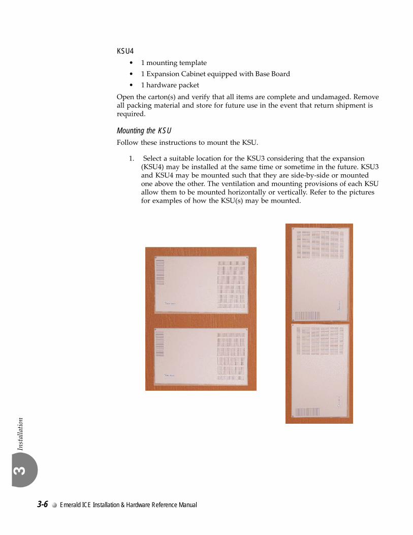
Mounting the KSUFollow these instructions to mount the KSU.
1. Select a suitable location for the KSU3 considering that the expansion (KSU4) may be installed at the same time or sometime in the future. KSU3 and KSU4 may be mounted such that they are side‐by‐side or mounted one above the other. The ventilation and mounting provisions of each KSU allow them to be mounted horizontally or vertically. Refer to the pictures for examples of how the KSU(s) may be mounted.
3-6 Emerald ICE Installation & Hardware Reference Manual

Installation
3
2. Using the mounting template as a guide, mark the two (2) mounting screws locations on the TMB for he mounting position preferred.
3. Pre‐drill two (2) screw holes and install the two, pan‐head No. 10 screws (supplied) into the backboard with a screwdriver. The screw heads should protrude about 2cm from the backboard plywood surface.
Emerald ICE Installation & Hardware Reference Manual 3-7

Installation
3
4. Lift the KSU over the two screws allowing the screws to extend into the
KSU slotted mounting holes. As the KSU is allowed to rest in place on the mounting screws it will slip over the screw shanks until the top of the slot is reached. Properly installed, the KSU cover will swing open to the bottom or to the right side depending on horizontal or vertical mounting. Appropriate spacing should be considered for the swing of the cover such that it can be opened sufficiently to perform work inside the cabinet.
It is very important that the KSU be correctly mounted to allow proper power supply heat dissipation. KSUI and KSU4 are intended to be wall mounted only. Mount each KSU using the slotted mounting holes as they were intended to assure compliance with this important heat-dissipation requirement.
Ground the KSU. Extend Earth Ground into the KSU(s) using #10AWG wire. Terminate the grounding wire onto the ground lug provided there. A “known good” earth ground must be connected. Examples of good earth grounds are:
3-8 Emerald ICE Installation & Hardware Reference Manual

Installation
3
• Cold water pipe ‐ where the pipe is known not to have plastic or PVC insula‐tors in‐line.
• Ground Rod ‐ where the grounding rod is known to meet local electrical specifications for grounding rod installation. The grounding rod in the photo is 2.5m (10ft) long.
Battery Connections (System Battery Back Up)Connection of an external battery back up source is optional. Use the chart of Power Consumption of Components Installed in the Specifications section to determine the required battery supply necessary to maintain system functionality for the duration desired at this site. Use the following to install System Back‐Up Batteries:
The battery charging board is mounted at the Power Supply voltage regulator
Danger of explosion if battery is incorrectly replaced!
Replace only with the equivalent type recommended by the manufacture. Dispose of used batteries according to the battery manufacturer's instructions.
Emerald ICE Installation & Hardware Reference Manual 3-9

Installation
3
MDF (Main Distribution Frame)The various ports of the Emerald ICE are extended to the MDF using industry standard 4, 12, and 25 pair UTP (Unshielded Twisted Pair) cable. Inside the KSU pairs are terminated using screw terminal posts, modular ended crimping connectors and AMP‐type Male gender connectors. These cables are then routed out of the KSU to the 66M1‐50 blocks for termination and jumper‐wiring there. The installer has choices when completing these connections and it is left to the installer’s discretion to use the most suitable industry standard wiring practice for the particular installation. In the examples of this manual, standard 66M1‐50 connectors are used. The following example illustrates a two‐cabinet installation with the KSUs mounted vertically and side by side.
MDF cables are routed out of the KSU through the opening in the corner of the KSU housing. A cable restraint clamp is provided and may be used to secure cables at that point.
3-10 Emerald ICE Installation & Hardware Reference Manual

Installation
3
When routing cables to the appropriate connector in the KSU the Removable Access Panel can be temporarily removed to allow easy access to the various KSU connections.
Important! Replace the Removable Access Panel after all connections have been made. The panel is required to be in position to comply with FCC regulations.
The 66Ml‐50 is split into a left half and right half for wiring terminations.
Each row is conductive between the left two columns and the right two columns. This is the source of the term “Split 50.”
Terminate cable pairs from the KSU and from telephone locations on outer column pins, one lead only per pin. NEVER terminate two wires on one pin! This is referred to as “double‐punching” and causes poor connection of wires on the terminal.
Emerald ICE Installation & Hardware Reference Manual 3-11

Installation
3
66M1-50 Pinouts
Emerald ICE boards equipped with 25 pair AMP‐type cable connectors are:
• KSU3 610+2 Board• 12EKT• KSU4 Base Board
Refer to the charts on the following pages for pinout designations per cable pair for each board type and associated connector.
3-12 Emerald ICE Installation & Hardware Reference Manual

Installation
3
Emerald ICE Installation & Hardware Reference Manual 3-13

Installation
3
3-14 Emerald ICE Installation & Hardware Reference Manual

Installation
3
The Emerald ICE system permits 2 Door Phone extensions to be connected with the 610+2 Board. The extensions are analog and are used to activate relays which are connected with the on‐site door opening circuit or ancillary device.
Telephone keys can be programmed using either the Deluxe Telephone or the RMP to open the door and set the unlocked time.
Up to 6 extensions per door phone can be programmed to ring when the door phone is activated.
Instllation of the Emerald ICE Door Phone consists fo the following:
1. Connection with the 610+2 Board.
2. Connection of the door phone to the Emerald ICE KSU.
3. Installation of the Mounting Bracket and mounting of the Door Phone.
4. Connection of the door phone and relays.
4. Deluxe Telephone Programming or RMP Programming.
Figure 3-1 Emerald ICE Door Phone
The door phone extensions are preprogrammed for extensions 411 and 412.
The default Door Unlocked time is defaulted to 250 milliseconds.
3.3 Door Phone Installation
Emerald ICE Installation & Hardware Reference Manual 3-15

Installation
3
Hardware Installation
Installing the hardware consists of removing the existing jumper connectors on the 610+2 board, installing the mounting bracket, wiring the Door Phone to the board and connecting your door opener with the relays on the 610+2 board.
The dimensions fo the door phone are: W= 3.75 Inches: H= 5 inches: D=1.25 inches
Procedures1. Power down the KSU, if it is not powered down already.
2. Find jumpers SLT1 and SLT2 on the 610+2 board and remove the straps as necessary. SLT1 is for extension 411 and SLT2 is for extension 412.
3.75 inches
5 inches
1.25 inches
3-16 Emerald ICE Installation & Hardware Reference Manual

Installation
3
3. Remove the Mounting Bracket from the Door Phone by removing the Mating Screw.
4. Install the Mounting Bracket on the desired Door Phone location using the mounting screws and moorings supplied. The Mounting Bracket should be secured using the mounting holes. The location should be close to a wiring accsess point and the door being locked or unlocked.
5. The 24th and 25th pairs are used on the connector to the 610+2 card and connected with the SLT2 and SLT1 connections on the card as follows:
Extension 411 ‐ SLT1 ‐ violet‐brown pair
Extension 412 ‐ SLT2 ‐ violet‐slate pair.
Mating Screw
Mounting Bracket
Door Phone
Mounting Holes
Mounting Hardware
Emerald ICE Installation & Hardware Reference Manual 3-17

Installation
3
Connect the desired pairs to the Door Phone Terminals as shown below:
6. Reattach the wired Door Phone to the Mounting Bracket using the Mating Screw.
7. Connect your door opener with the desired relays on the 610+2 Board using the tightening screws to secure wiring in the lower terminals of the relays. The relays are 1 amp relays that close a loop circuit when a programmed unlocking code is pressed on a telephone keypad. When the circuit is closed, the on‐site door opening mechanism will activate to unlock the door.
Contact your Site Adminstrator or Facilities Administrator for wiring and other information on the door opening mechanism installed at your site.
Note that the DSTA1 and DSTA2 relays are reserved for future use and are not for use at this time.
Terminals
Lower Terminals
Tightening Screws
3-18 Emerald ICE Installation & Hardware Reference Manual

Installation
3
Programming
Programming the Emerald ICE Door Phone is accomplished using a Deluxe Telephone Set or the Emerald ICE RMP.
Deluxe Telephone Programming1. Access the Deluxe Telephone Programming Features as described in
Section 3.2.
2. Enter 06-04 to enter the Door Phone Programming mode.
3. Press the softkey beneath show to display the following;
4. Press the softkey beneath show to advance to the DOOR PHONE selection screen. Toggle the softkey beneath chg to select the desired Door Phone to program.(1 or 2)
5. Press the softkey beneath show to access the DAY member selection screen. These are the Day extensions that will ring when the Door Phone is activated. When the Emerald ICE system is in the Day Service Mode up to 6 extensions/Hunt Groups (UCD) may be assigned to ring for the Door Phone.
DOOR PHONE
back next show
RING POSITION
back next show
DOOR PHONE
bksp show chg
DAY
back next show
Emerald ICE Installation & Hardware Reference Manual 3-19
Installation
3
6. Press the softkey beneath show to add Day members to the ring list. By default, NULL will be displayed until a new member is added. Enter a 3‐digit extension from using the telephone keypad and then press the softkey beneath next to add additional extensions.
7.When all of the desired extensions have been added, press the h button to return to the Day programming screen. Press the softkey beneath next to access the Night Mode programming screens. When the Emerald ICE system is in the Night Service Mode, 1 extension/Hunt Group (UCD) may be assigned to ring for the Door Phone.
8. Enter a 3‐digit extension from using the telephone keypad. If changing an extension, press the softkey beneath chg to change an existing extension. If no extensions were entered previously, NULL will be displayed.
9. When the desired Night mode extension has been added, press softkey beneath next to advance to the Unlock Code programming screen. If connected to the Door Phone, any dial pad digit can be pressed to trigger the relay and operate the door opener. Press the soft key beneath chg to scroll through Unlock Code characters. (Range: 0~9, *, #; Default: #)
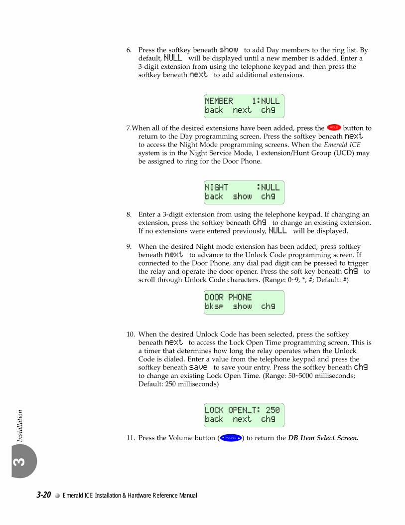
10. When the desired Unlock Code has been selected, press the softkey beneath next to access the Lock Open Time programming screen. This is a timer that determines how long the relay operates when the Unlock Code is dialed. Enter a value from the telephone keypad and press the softkey beneath save to save your entry. Press the softkey beneath chg to change an existing Lock Open Time. (Range: 50~5000 milliseconds; Default: 250 milliseconds)
11. Press the Volume button (V) to return the DB Item Select Screen.
MEMBER 1:NULL
back next chg
NIGHT :NULL
back show chg
DOOR PHONE
bksp show chg
LOCK OPEN_T: 250
back next chg
3-20 Emerald ICE Installation & Hardware Reference Manual

Installation
3
RMP Programming1. Access the RMP using the procedures described in Section 3.3.
2. Select RP, Extension Application, Door Phone from the toolbar to display the following window.
Door Phone 1 represents extension 411. Door Phone 2 represents extension 412.
Using the drop down lists, select extensions and and timers as follows:
Member (1‐6) ‐ When the Emerald ICE system is in the Day Service Mode, up to 6 extensions/Hunt Groups (UCD) may be assigned to ring for the Door Phone. (Range: 401‐472, 230‐253).
Evening No. ‐ When the Emerald ICE system is in the Night Service Mode, 1 extensions/Hunt Groups (UCD) may be assigned to ring for the Door Phone. (Range: 401‐472, 230‐253).
Max Ring Time: ‐ Since the Door Phone Call button can be pressed and then abandoned, a maximum ring time must be set. (Range: 10, 20, ...60; Default: 20).
Unlock Code: ‐ While connected to the Door Phone and dial pad digit can be pressed to trigger the relay and operate the door opener. This code can be changed here. (Range: 0‐9, *, #; Default: #)
Door Lock Open Time: ‐ This timer determines how long the relay operates when the Unlock Code is dialed. (Range: 50~5000 milliseconds; Default: 250 milliseconds).
Emerald ICE Installation & Hardware Reference Manual 3-21

Installation
3
3-22 Emerald ICE Installation & Hardware Reference Manual

4
RMP SetupRMP Setup
4
Description
Programming the Emerald ICE for the various features is executed using the 28‐Button (Deluxe) Telephone or the Remote and Maintenance Programming (RMP) application on a PC.
The RMP is a Microsoft® Windows® based application that utilizes checkboxes, drop down lists and selection lists to program the various features.
Figure 4-1 RMP Interface
4.1 General
Emerald ICE Installation & Hardware Reference Manual 4-1

RMP Setup
4
The RMP application is included with the Documentation CD and RMP Installer supplied with the KSU. Insert the CD into a PC and a menu of selections will be generated. The CDʹs autorun feature will display a menu of choices. These include documentation, a CBT, DESI Labels and the RMP Installer.
Figure 4-2 CD Menu of Choices
Click on the RMP Installer button as shown and follow the prompts to install the application onto your PC.
RMP Installer
CBT
Documentation
4-2 Emerald ICE Installation & Hardware Reference Manual

RMP Setup
4
Your PC must be connected with the Emerald ICE via a Straight 9‐Pin Connector Cable which connects on the top of the CCB Board to a COM port on your PC.
Figure 4-3 Straight 9-pin Connection to CCB Board
After installing the RMP application and connecting your PC with the KSU, you are now ready to initialize your system.
Refer to the Emerald ICE Feature Programming Manual for instructions on programming the various system features.
Connectionto CCB Board
Emerald ICE Installation & Hardware Reference Manual 4-3
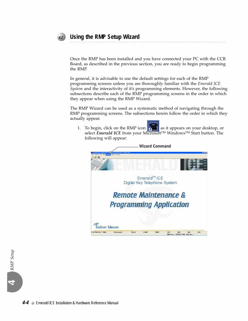
RMP Setup
4
Once the RMP has been installed and you have connected your PC with the CCB Board, as described in the previous section, you are ready to begin programming the RMP.
In general, it is advisable to use the default settings for each of the RMP programming screens unless you are thoroughly familiar with the Emerald ICE System and the interactivity of it’s programming elements. However, the following subsections describe each of the RMP programming screens in the order in which they appear when using the RMP Wizard.
The RMP Wizard can be used as a systematic method of navigating through the RMP programming screens. The subsections herein follow the order in which they actually appear.
1. To begin, click on the RMP icon as it appears on your desktop, or select Emerald ICE from your MicrosoftTM WindowsTM Start button. The following will appear:
4.2 Using the RMP Setup Wizard
Wizard Command
4-4 Emerald ICE Installation & Hardware Reference Manual

RMP Setup
4
2. Click on the Wizard command from the menu bar as shown above. The following selection screen will be shown.
3. Click on the Create button if you haven’t previously set up an ICE database.
4. Enter a file name in the area provided that will be used as your ICE database. Click on the Save button when you have finished.
The RMP screens will now be sequentially displayed and made available to you to program.
It is highly recommended that you accept all of the RMP default settings unless you are thoroughly familiar with the Emerald ICE System and it’s features and the Voicemail options available to add on to the system.
Refer to the Emerald ICE Installation Training Module on the CD included with your system for detailed descriptions of the fields on each of the RMP screens or the Emerald ICE Feature Programming Manual for programming specific features.
Database File Name
Emerald ICE Installation & Hardware Reference Manual 4-5

RMP Setup
4
4-6 Emerald ICE Installation & Hardware Reference Manual

5
System InitializationSystem Initialization
5
Proceed with the following to initialize the KSU.
1.Verify that the KSU power is OFF.
2.Verify that the jumper pins on J7 on the CCB Board are in the ʺCold Position.
3.‘Power up the KSU and wait 10 seconds.
4.Power down the KSU and move the J7 pins to the ʺNormalʺ position.
KSU Power Switch
J7 Pins to NORMAL
J7 Pins to COLD
Emerald ICE Installation & Hardware Reference Manual 5-1

System Initialization
5
5.Power up the KSU again.
6.Verify that the telephones have been initialized. A date and time display will be visible on the Deluxe telephones. For a Standard telephone, a dial tone will be heard.
7.Enter the RMP programming mode. Select RM, Remote Control and perform a Software Cold Start.
8.It should be approximately 30 seconds before a display is visible on the Deluxe Telephones or a Dial Tone is heard on a Standard Telephone.
9.When a display is visible on the Deluxe Telephones or a Dial Tone is heard on a Standard Telephone, power down the KSU, wait 15 seconds, and then power up the KSU again.
Deluxe Telephone Standard Telephone
Date & Time Display Dial Tone
5-2 Emerald ICE Installation & Hardware Reference Manual

6
T1/PRI Card Installation and SetupT1/PRI Card Installation and Setup
6
The T1/PRI Card is installed on the Base Board of Emerald ICE KSU4.
In order for the T1/PRI cards to be functional, an LLP Card must be installed on the 610+2 Card.
Outgoing PRI Calls
Outgoing PRI Trunk connections can be made by dialing the Trunk Group Code (according to the programming of the CO Route for the PRI trunks and the Trunk Route Numbering Plan) or pressing the individual PRI Trunk button.
When accessing a Trunk via Trunk Group access, system will try to select one idle and available PRI trunk from the Route first according to the Hunt Method set for the Route. If no PRI trunk is available, system will select another trunk instead according the Alternate Route programming in the database.
While trying to access an idle PRI trunk, if the PRI trunk is temporarily unavailable and released due to any cause from Network, the call will be dropped and the LCD of the EKT will be displayed for 5 seconds with Congestion Tone.
If CLIP (Calling Line Identification Presentation) of the CO Route which the trunk is seized is set to “Present” or the Send Caller ID of the Extension making the call is ‘Y’, CLIP will be included in the T_Setup message and Calling Party Number will be sent to the Network.
6.1 Description
Emerald ICE Installation & Hardware Reference Manual 6-1

T1/PRI Card Installation and Setup
6
Incoming PRI Calls
After an incoming call arrives, DID(DDI) digits are received by the system and checked against a Translation Table assigned for the CO Route of the PRI trunk.
If one entry is matched with the Translation Table, and the corresponding destination exists, the call will be rung or routed to the destination. Otherwise, the call will ring to a programmed Intercept.
If an Intercept is not programmed, it will ring the Tenant Attendant.
If COLP (Connected Line Identification Presentation) of the CO Route which the trunk is incoming is set to “Preset” or the Send Caller ID of the Extension which answers the call is ‘Y’, COLP will be included in the T_Connect_Out message and the Answering Party Number will be sent to the Network after the extension answers the PRI call.
If the incoming PRI call is translated and routed for an outgoing trunk call, the PRI trunk’s COS will be referenced for Toll Restriction checking when making the outgoing call. No Answering Party Number will be sent to the Network in such case.
The incoming PRI Trunk Call will ring the destination (Extension or Hunt Group) until the destination answers or the outside party abandons the trunk.
Call Operation (Hold and Transfer) for the PRI Trunk call operated by the extensions will follow the ordinary trunk call operations in the Emerald ICE system.
T1 Calls
Loop StartSimilar to Analog Trunk with Loop Start.
Ground StartSimilar to Analog Trunk with Ground Start. A “Tip Ground” must be detected first and then the dialed number would be sent to CO for the outgoing trunk call.
For outgoing trunk calls, after a Ground tip ‘0,X’ is received the transmit signaling must be changed from ‘0,0’ to ‘0,1’ and then changed to ‘1,1’ immediately.
6-2 Emerald ICE Installation & Hardware Reference Manual

T1/PRI Card Installation and Setup
6
DIDUsed for incoming trunk calls only. After receiving an incoming call signaling, the DSP on the T1 is receives the Caller ID and DID number in “DTMF”. Dial Tone will be provided to the incoming DID trunk. After the Caller ID (if provided) and DID number are received, the destination corresponding to the Service Mode (Day / Night) by that time will be received after checking against the Translation Table programmed for that Trunk Route of the T1Trunk. If no destination is found or the destination does not exist, the incoming call will be routed to a programmed Intercept extension. If the Intercept is not programmed, it will ring to the Tenant Attendant. If no DID digit in DTMF is received within 10 seconds, the trunk will be routed to the Intercept No. and the call will ring to the Intercept. If the Intercept is not programmed, it will ring to the Tenant Attendant.
Call Forward will operate if the designated extension has Call Forward set or Predefined CFW programmed.
If the final called extension is busy, a busy tone will be provided to the far end.
If the final called extension is in DND, a congestion tone will be provided to the farend.
If the incoming call is translated and routed for an outgoing trunk call, the incoming T1 trunk’s COS will be referenced for Toll Restriction checking when making the outgoing call.
The incoming Call will ring the destination (Extension or Hunt Group) until the destination answers or the outside party abandons the trunk.
Call Operation (Hold and Transfer) for the T1 Trunk call operated by the extensions will follow the ordinary trunk call operations in the Emerald ICE system.
E&M
Outgoing CallsImmediate Start ‐ Similar to Loop Start Trunk.
Wink Start ‐ A ‘wink’ must be detected first, and the dialed number will be sent to a CO line. If the system does not get the ‘wink’, the call will be dropped.
Incoming CallSimilar to DID Trunk. For an incoming Wink Start Trunk Call, a Wink Start (Transmit Signaling: ‘0,0’ ‘1,1’ ‘0,0’) must be provided from T1 card.
The operation for an incoming E&M trunk is the same as DID trunk.
Emerald ICE Installation & Hardware Reference Manual 6-3

T1/PRI Card Installation and Setup
6
Prerequisites
In order for the T1/PRI cards to be functional, an LLP Card must be installed on the 610+2 Card as shown below in Figure 6-1.
Figure 6-1 610+2 Card with LLP Card Installed.
6.2 Installation
LLP Card
610+2 Card
6-4 Emerald ICE Installation & Hardware Reference Manual

T1/PRI Card Installation and Setup
6
Installation on KSU4
1. Turn off the power on the KSU4 (Expansion) cabinet if it is on.
2. Install the T1/PRI Card on the Base Board of KSU4 (Expansion Cabinet)using the Standoffs (4) provided.
3. Connect the Connector Cable from T1/PRI Card to the marked ConnectorSlot on the T1/PRI Card.
4. Connect an RJ45 or 15‐Pin connector to the T1/PRI Card, based on thetype of connectivity provided by your TELCO.
5. Turn the power on KSU4 to “ON”. When a link is established the follow‐ing Link Indication LED’s will be illuminated.
6. Proceed with the RMP Programming in the following section.
T1/PRI Card (PRI Shown)
Base Board
KSU4
Connector Cable
Standoffs (4)
Connector Slot
RJ45 15-Pin Link Indication LED’s
Green
Emerald ICE Installation & Hardware Reference Manual 6-5

T1/PRI Card Installation and Setup
6
T1 and PRI Setup
Steps 1 through 7 below describe the procedure of configuring the Emerald ICE system using the RMP to operate with both the T1 and PRI cards.
The sections that follow describe additional programming if you are setting up the T1 card.
1. Open your Emerald ICE database file and connect with the RMP.
2. Select RP, Call Handling, Feature Control as shown below.
3. On the RP, Call Handling‐Feature Control Screen shown below, the Syn‐chronization Source field must be 3rd BRI Slot.
Click on the Update button to enter your settings into the RMP database.
6.3 RMP Setup
6-6 Emerald ICE Installation & Hardware Reference Manual

T1/PRI Card Installation and Setup
6
4. Select RP, CO Line Application, CO Line Group Setting as shown below.
5. On the RP: CO Line Application ‐ CO Line Group Setting screen shownbelow, set the Translation Table Selection to a recommended setting of 8.“0” cannot be used. There are 8 Translation Tables that can be assigned todifferent CO Routes.
Click on the Update button to enter your settings into the RMP database.
Emerald ICE Installation & Hardware Reference Manual 6-7

T1/PRI Card Installation and Setup
6
6. Select RP, CO Line Application, Translation Table as shown below.
7. Proceed with the following on the RP: CO Line Application‐TranslationTable:
a. Change the Translation Table No. field concur with he number of the table that you selected in step 6.
b. Enter the DID Length of the extensions. This specifies the number of DID (DDI) digits that will be sent from the Digital Trunk in the CO Route for which the Table is assigned. The options are from 0’ to ‘12. Default is 0.
c. Enter an extension number in the Intercept field. This item specifies the Extension or Hunt Group directory Number to which the Incoming Digital calls will be routed if a match for the Incoming DID (DDI) Digits is not in the Translation Table. The Intercept can be either an Extension Directory No. or Hunt Group Directory No. The default is NULL.
6-8 Emerald ICE Installation & Hardware Reference Manual

T1/PRI Card Installation and Setup
6
d. Enter a value in the Incoming field. This field specifies the digits that will be received on the Digital Trunk in the CO Route for which the Translation table is assigned. When digits are received, they will be compared to this Incoming field. When a match is found, the number will be translated into the associated Destination Number. 12 digits (0‐9, X) can be programmed. Default is “Null” for all entries.
e. Enter a value in the Destination (Day) Field . This field specifies the Number to which the Incoming digits are translated in Day Service Mode. The Destination Number can be an Extension, Hunt Group, Operator, System Speed Dial, LCR or Trunk Route Directory Number. The Destination Number can have a different number of digits than the Incoming Number entry. 12 digits (0‐9, X) can be programmed. The Default is Null for all entries.
f. Enter a value in the Destination (Night) Field. This field is similar to the Destination (Day), however, it works for Night Service Mode.
When you have completed entering information from steps d, e, and f, click on the button to enter your information into the table. Click on the Update button to enter your settings into the RMP database.
T1 Setup
After completing steps 1 through 7 above, proceed with the following to set up the RMP for operation with the T1 card.
1. Select RP, CO Line Application, T1 Card as shown below.
Emerald ICE Installation & Hardware Reference Manual 6-9

T1/PRI Card Installation and Setup
6
2. Proceed with the following on the RP: CO Line Application‐T1 Card‐T1Setting Screen:
a. Select a radio button to designate a Frame Type (System). The options are D4 and ESF. The default is D4. The Frame Type is usually determined by your TELCO.
b. Select a radio button to designate a Zero Code Suppression Scheme (System). The options are AMI and B8ZS. The default is AMI. The Zero Code Suppression Scheme is determined by your TELCO.
c. Select a radio button to disgnate a System Loop Back Setting (System). The options are None, Local and Remote. The default is None. It is recommended that you select None for this field.
d. Select a Wink Duration. The TX Duration range is from 50ms to 500ms. The increment is 50ms and the default is 200ms. The RX Duration range is from 50ms to 500ms. The increment is 50ms and the default is 500ms.
e. In the Caller ID area you must select a Start Digit, End Digit and program the Length. A Start Digit can be DTMF 0‐9,*,#,A,B,C,D, and the default is *. The End Digit can be DTMF 0‐9,*,#,A,B,C,D, and the default is *. The Length can be 0‐15, and the default is 10.
Click on the Update button to enter your settings into the RMP database.
6-10 Emerald ICE Installation & Hardware Reference Manual

T1/PRI Card Installation and Setup
6
3. Select RP, CO Line Application, T1 Card, Channel Settings as shownbelow.
4. There are 24 T1 channels available‐ each assigned to a Trunk directory.Each channel must be programmed to designated the type of channel andif the Loop Back option is available on that channel. Double click on aChannel No. in the RP: CO Line Application ‐T1 Card ‐Channel Settingsscreen.
a. For each Channel No./Trunk Dir selected, select a Channel Type from the drop‐down selection list provided. Select Loop Start, Ground Start, DID (Direct In Dial)(Analog), Intermediate Start E&M or Wink Start E&M. The default is Wink Start E&M.
Loop Start ‐ Similar to Analog Trunk with Loop Start.
Ground Start ‐ Similar to Analog Trunk with Ground Start. A “Tip Ground” must be detected first and then the dialed number would be sent to CO for the outgoing trunk call.
Emerald ICE Installation & Hardware Reference Manual 6-11

T1/PRI Card Installation and Setup
6
DID (Direct In Dial) ‐ Used for incoming trunk calls only. After receiving an incoming call signaling, the DSP on the T1 receives the Caller ID and DID number in “DTMF”. Dial Tone will be provided to the incoming DID trunk. After the Caller ID (if provided) and DID numbers are received, the destination corresponding to the Service Mode (Day / Night) by that time will be received after checking against a Translation Table programmed for that Trunk Route of the T1Trunk. If no destination is found or the destination does not exist, the incoming call will be routed to a programmed Intercept extension. If the Intercept is not programmed, it will ring to the Tenant Attendant. If no DID digit in DTMF is received within 10 seconds, the trunk will be routed to the Intercept No. and the call will ring to the Intercept. If the Intercept is not programmed, it will ring to the Tenant Attendant.
Immediate Start E&M ‐ Similar to Loop Start Trunk.
Wink Start E & M‐ A ‘wink’ must be detected first, and the dialed number will be sent to a CO line. If the system does not get the ‘wink’, the call will be dropped.
b. Using the checkbox, select whether the programmed channel will Loop Back.
c. Click on the button to enter your information, for each channel, into the table.
5. Click on the Update button to enter your settings into the RMP database.
6-12 Emerald ICE Installation & Hardware Reference Manual

T1/PRI Card Installation and Setup
6
T1 and PRI Setup
Steps 1 through 7 below describe the procedure of configuring the Emerald ICE system using a Deluxe Telephone Set to operate with both the T1 and PRI cards.
The sections that follow describe additional programming if you are setting up the T1 card.
1. Follow the sequence below to enter the Emerald ICE databaseusing a Deluxe Telephone Set.
2. On the keypad of your Deluxe Telephone Set, select 03-51 and thenpress the softkey beneath save to display the SYNC_SOURCE screen.
3. Toggle the softkey beneath chg to select 3 which represents the 3rd BRISlot. Press the v button when finished.
4. On the keypad of your Deluxe Telephone Set, select 07-03- TranslationTable ‐ 01. The recommended Translation Table setting is “8”. “0” can‐not be used. There are 8 Translation Tables that can be assigned to differ‐ent CO Routes. Press the softkey beneath save and DDI LENGTH willbe displayed.
5. Continously press the softkey beneath chg to enter the DID Length of theextensions. This specifies the number of DID (DDI) digits that will be sentfrom the Digital Trunk in the CO Route for which the Table is assigned.The options are from “0” to “12”. Default is 0. Press the softkey beneathnext to continue.
6.4 Deluxe Telephone Setup
Emerald ICE Installation & Hardware Reference Manual 6-13

T1/PRI Card Installation and Setup
6
6. At the INTERCEPT display, enter an extension number in the Interceptfield. This item specifies the Extension or Hunt Group directory Numberto which the Incoming Digital calls will be routed if a match for theIncoming DID (DDI) Digits is not in the Translation Table. The Interceptcan be either an Extension Directory No. or Hunt Group Directory No.The default is NULL. Press the softkey beneath next to continue.
7. At the SHOW ENTRY display press the softkey beneath show. Enter anentry number to show Destination (Day) Field and Destination (Night)Fields. Up to 40 entries are available. Press the soft key beneath save to con‐tinue.
8. At the INCOMING display, press the softkey beneath show to enter newvalues or display the existing values.
9. After pressing the softkey beneath show, enter a value in the Incomingfield. This field specifies the digits that will be received on the DigitalTrunk in the CO Route for which the Translation table is assigned. Whendigits are received, they will be compared to this Incoming field. When amatch is found, the number will be translated into the associated Destina‐tion Number. 12 digits (0‐9, X) can be programmed. Default is “Null” forall entries. Press the softkey beneath next to continue.
10. At the DAY DEST display, press the softkey beneath show to enter newvalues or display the existing values.
11. After pressing the softkey beneath show, enter a Day Destination num‐ber. This field specifies the Number to which the Incoming digits aretranslated in Day Service Mode. The Destination Number can be anExtension, Hunt Group, Operator, System Speed Dial, LCR or TrunkRoute Directory Number. The Destination Number can have a differentnumber of digits than the Incoming Number entry. 12 digits (0‐9, X) canbe programmed. The Default is Null for all entries. Press the softkeybeneath next to continue.
12. At the NIGHT DEST display, press the softkey beneath show to enternew values or display the existing values.
13. After pressing the softkey beneath show, enter a Night Destination num‐ber. This field is similar to the Destination (Day), however, it works forNight Service Mode. Press the v button when finished.
6-14 Emerald ICE Installation & Hardware Reference Manual

T1/PRI Card Installation and Setup
6
T1 Setup
After completing steps 1 through 13 above, proceed with the following to set up the Emerald ICE system on the Deluxe Telephone for operation with the T1 card.
1. On the keypad of your Deluxe Telephone Set, select 07-05 andthen press the softkey beneath save to display the T1 CARD
display. Press the softkey beneath show to display all of the set‐tings.
2. Press the softkey beneath next 2 times to display the FRAME TYPE dis-play. This designates a Frame Type (System). Toggle the softkey beneathchg to make a selection. The options are D4 and ESF. The default is D4.The Frame Type is usually determined by your TELCO. Press the softkeybeneath next to continue.
3. At the ENCODE display continously press the softkey beneath chg to des‐ignate a Zero Code Suppression Scheme (System). The options are AMIand B8ZS. The default is AMI. The Zero Code Suppression Scheme isdetermined by your TELCO. Press the softkey beneath next to continue.
4. At the LOOP BACK display continously press the softkey beneath chgto designate a System Loop Back Setting (System). The options areNONE, LOCAL and REMOTE. The default is NONE. It is recommendedthat you select NONE for this field. Press the softkey beneath next to con‐tinue.
5. At the WINKTX display continuously press the softkey beneath chg todesignate a TX Duration. The TX Duration range is from 50ms to 500ms.The increment is 50ms and the default is 200ms. Press the softkey beneathnext to continue. Press the softkey beneath next to continue.
6. At the WINKRX display, continously press the softkey beneath chg todesignate an RX Duration. The RX Duration range is from 50ms to 500ms.The increment is 50ms and the default is 500ms. Press the softkey beneathnext to continue.
7. At the CALLER ID START display, continously press the softkeybeneath chg to designate a Caller ID Start digit. A Start Digit can beDTMF 0-9,*,#,A,B,C,D. The default is *. Press the softkey beneath nextto continue.
8. At the CALLER ID END display, continously press the softkey beneathchg to designate a Caller ID End digit. The End Digit can be DTMF0-9,*,#,A,B,C,D. The default is *. Press the softkey beneath next to con‐tinue.
9. At the MAX LENGTH display, continously press the softkey beneath chgto designate a maximum length. The Length can be 0-15 digits. Thedefault is 10. Press the v button when finished.
Emerald ICE Installation & Hardware Reference Manual 6-15

T1/PRI Card Installation and Setup
6
10. On the keypad of your Deluxe Telephone Set, select 07-05-O3 and thenpress the softkey beneath save to display the CHANNEL SETTINGS
display. Press the softkey beneath show to display all of the settings.
There are 24 T1 channels available- each assigned to a Trunk directory. Each channel must be programmed to designated the type of channel and if the Loop Back option is available on that channel.
11. At the CHANNEL SETTINGS display enter a channel number and thenpress the softkey beneath show to display the settings.
12. At the CHAN. TYPE display continously press the softkey beneath chgto select a channel type. Available selections are LOOP (Loop Start),GROUND (Ground Start), DID (Direct In Dial)(Analog), I_E&M (Inter‐meddiate E&M) or W_E&M (Wink E&M). The default is W_E&M. Press thesoftkey beneath next to continue.
Loop Start is similar to Analog Trunk with Loop Start. Ground Start is similar to Analog Trunk with Ground Start. A “Tip Ground” must be detected first and then the dialed number would be sent to CO for the outgoing trunk call. Press the v button when finished.
6-16 Emerald ICE Installation & Hardware Reference Manual

T1/PRI Card Installation and Setup
6
DID (Direct In Dial) ‐ Used for incoming trunk calls only. After receiving an incoming call signaling, the DSP on the T1 receives the Caller ID and DID number in “DTMF”. Dial Tone will be provided to the incoming DID trunk. After the Caller ID (if provided) and DID numbers are received, the destination corresponding to the Service Mode (Day / Night) by that time will be received after checking against a Translation Table programmed for that Trunk Route of the T1Trunk. If no destination is found or the destination does not exist, the incoming call will be routed to a programmed Intercept extension. If the Intercept is not programmed, it will ring to the Tenant Attendant. If no DID digit in DTMF is received within 10 seconds, the trunk will be routed to the Intercept No. and the call will ring to the Intercept. If the Intercept is not programmed, it will ring to the Tenant Attendant.
Immediate Start E&M ‐ Similar to Loop Start Trunk.
Wink Start E & M‐ A ‘wink’ must be detected first, and the dialed number will be sent to a CO line. If the system does not get the ‘wink’, the call will be dropped.
b. Using the checkbox, select whether the programmed channel will Loop Back.
Emerald ICE Installation & Hardware Reference Manual 6-17

T1/PRI Card Installation and Setup
6
6-18 Emerald ICE Installation & Hardware Reference Manual
