design and fabrication of integrated dual hydraulic jacks ... · the proposed integrated hydraulic...
TRANSCRIPT
International Research Journal of Engineering and Technology (IRJET) e-ISSN: 2395-0056
Volume: 05 Issue: 04 | Apr-2018 www.irjet.net p-ISSN: 2395-0072
© 2018, IRJET | Impact Factor value: 6.171 | ISO 9001:2008 Certified Journal | Page 3847
Design and Fabrication of Integrated Dual Hydraulic Jacks for Four Wheelers
Aju A. S.1, Amal B.2, Nisanth R.3, Nithin J.4, Mr. Robin David5, Mr. Avinash G. S.6.
1,2,3,4 UG students, Department of Mechanical Engineering, VAST TC, Kilimanoor 5, 6 Assistant Professor, Department of Mechanical Engineering, Vidya Academy of Science and Technology
Technical Campus, Kilimanoor, Kerala, India -----------------------------------------------------------------------------***-------------------------------------------------------------------------------
Abstract – The objective of this paper is to develop an integrated dual hydraulic jack system in vehicles. In most of the garages the vehicles are lifted by using a separate screw jack. This needs high man power and skilled labours. The intention of this paper is to develop an integrated hydraulic jack system that can be operated by driver from inside the car. The vehicle chassis is fitted with a hydraulic jack system which is operated by a pump that supplies pressurized oil to the hydraulic cylinder. By pressing the button in the dashboard, it activates the hydraulic jack automatically. The paper deals with the guidelines for designing various components used in the integrated hydraulic jack system and the installation of the assembled system to a vehicle chassis. With the use of this system, the vehicles can be lifted from the floor land without application of any impact force. From the test results it is found that the hydraulic jack system performed well according to the present load conditions and can be extended to any static or dynamic load conditions. The motive behind using this system instead of a conventional mechanical system is the more power produced by the system and simple design. Since the hydraulic oil is incompressible so the lifting capacity is more in comparison with the pneumatic system which operates on air.
Keywords: Hydraulic jack, Pump, Actuator, Chassis, Hydraulic Cylinder & pneumatic.
1. INTRODUCTION
The invention relates to hydraulic jack and more specifically to an automobile hydraulic jack system. Tire puncture can be commonly observed nowadays. Car jack comes with vehicles requires users to apply manual force to lift a vehicle. The objective of the paper is to fabricate an integrated hydraulic jack system which will lift the vehicles from floor without application of large force. Pascal's law is the basis of hydraulic drive systems. It states that pressure exerted on a stationary fluid acts equally in all directions.
As a part of this work various journals related to lifting a vehicle were studied and it was found that the presently available systems have some limitations. In this paper we introduced a new concept of lifting a vehicle by designing an integrated hydraulic jack system for four-wheelers. A hydraulic system contains and confines a liquid in such a way that it uses the laws governing liquids to transmit power and do work. The proposed integrated hydraulic jack system consists of hydraulic cylinder, piston, piston rod, cover plate, base plate, connecting hoses, directional control valve, power supply and a fluid reservoir.
The two fluid reservoirs are mounted at the bottom of front and rear chassis and the fluid reservoir is mounted at convenient location and the directional control valve is mounted on the dashboard. When the vehicle is to be lifted in case of repairing, the driver can lift the vehicle by sitting inside the driver’s cabin by actuating the push button mounted on the dashboard. When the push button is actuated by the driver, the pressurized oil from the pump enters the hydraulic cylinder and transmits the load to the piston. The vehicle gets lifted as the piston moves in the cylinder.
This paper mainly deals with the design of various components used in integrated hydraulic jack system and the installation of the system in a vehicle chassis.
2. LITERATURE REVIEW
Ademola A. Dare and Sunday A. Oke et al described about the design and construction of a low price, simple mechanical jack with wedge mechanism to provide a lift of about 160 mm with a self-locking capability for both small and medium sized vehicles. The design calculations involve the evaluation of applied force required, the screw shaft design, and the lift head design analysis. The fabricated jack was tested on some small and medium vehicles, which resulted in a good lift without any pre-manual lifting.
Amit Tekawade, Jaydeep Wagh, Harshal Nemade, and Pranjal Vartak et al investigated in detail about jack with wedge mechanism. An electric motor was integrated with the worm gear jack and the electricity needed for the operation was taken from the battery of the vehicle or already charged battery and thereby the mechanical advantage would be increased, also Remote-control device can also be used to upgrade the model. The worm gear screw jack has ability to be used individually or linked mechanically and driven by electric motors or even manually. It has the lifting capacity of few kilos to the tones of weights with the raising capacity about 3 feet.
Choudhary S., Ravi Kumar D., Pasbola D., and Dabral S. et al discussed in detail about development in existing scissor car jack in order to make load lifting easier by utilizing car battery (12V) which can be used in emergency situations. In this design, the cigarette lighter receptacle point is connected in car, which drives the power from the car battery (12V), this will run the DC motor and thus connected power screw is rotated. By this, the car jack will lift the vehicle.

International Research Journal of Engineering and Technology (IRJET) e-ISSN: 2395-0056
Volume: 05 Issue: 04 | Apr-2018 www.irjet.net p-ISSN: 2395-0072
© 2018, IRJET | Impact Factor value: 6.171 | ISO 9001:2008 Certified Journal | Page 3848
Praveen C. P., Mithil R., Mijith C., Junufasin, Harilal N., and Harikrishnan U.et al described about converting the conventional hydraulic jack in to automated hydraulic jack by using linkage mechanism with a help of a motor.
K. Sainath, Mohd Salahuddinb Mohd, Jibran Baig, Md Azam Ali Farooky, Mohammed Siddique Ahmed, Mohd Riyaz Uddin, Faraz Ur Rehman Azhar, and Md Shaffi. et al described about the working and fabrication of a hydraulic jack in which hydraulic jacks depend on the basic principle to lift heavy load. This system uses pump plungers to move oil through two cylinders. The plunger is first drawn back, which opens the suction valve ball within and draws oil into the pump chamber. As the plunger is pushed forward, the oil moves through an external discharge check valve into the cylinder chamber, and the suction valve closes, which results in pressure building within the cylinder
P. S. Borkar, S. V. Sontakke, R. R. Dorwe, A. B. Ganorkar, and S. P. Lokhande et al described about the fabrication of pneumatic jack which deals with the study and application of pressurized air to produce mechanical motion. Pneumatic jack is a fabricated model which when installed in four-wheeler, will ease in the problems arising in the conventional operated jack.
3. PROBLEM IDENTIFICATION
A very important repair tool in the automobile industry is the vehicle jack. Essentially the jack is used in raising a vehicle sufficiently above the ground to remove tyres when required. A vehicle owner without a jack will, at an unguarded moment, suffer loss in time, finance and energy. There are two broad types of vehicle jack that can be obtained in practice, viz. the mechanical type and the hydraulic type. The mechanical jack can be of the scissors type or of a simple screw jack.
3.1 Motorized Screw Jack
Motorized screw jack is one of the major types of vehicle lifting mechanism used nowadays. A Screw jack is a device which is used to raise part of a vehicle in order to facilitate vehicle maintenances or breakdown repairs.
Fig. 1: Motorized Screw jack
3.2 Hydraulic Jack
Hydraulic jacks are widely used for lifting smaller to heavy vehicle. The hydraulic jack is working under the principle of Pascal’s law and the human effort can be reduced as compared to the screw jack system. Fluid power is utilized here for lifting vehicle
Fig. 2: Hydraulic jack
3.3 Pneumatic Jack
The pneumatic jacks are also widely used for lifting the vehicles. In this system air power is used for lifting the vehicle. Thus the man power is reduced here by the help of automation
Fig. 3: Pneumatic jack
From the literature review, it is observed that the following problems exist in commonly used jack systems in four-wheelers. The presently available vehicle lifting mechanisms were studied and they have some limitations and difficulties while operating the system and they are;
Failure encountered in some jacks is more frequent and effective repair is difficult
In the scissors jack excessive load acting on the driving screw frequently causes wear on the screw
A commercial production fulfilling all design requirements of existing jacks requires special equipment which includes a thread-rolling machine, a gear hobbling machine and other facilities.
International Research Journal of Engineering and Technology (IRJET) e-ISSN: 2395-0056
Volume: 05 Issue: 04 | Apr-2018 www.irjet.net p-ISSN: 2395-0072
© 2018, IRJET | Impact Factor value: 6.171 | ISO 9001:2008 Certified Journal | Page 3849
4. METHODOLOGY
Design of Integrated hydraulic Jack for four - wheelers requires the knowledge of Hydraulic system, directional control valves used in automobiles, fluid dynamics, basic machine design and Pascal’s law. The purpose of this paper is to describe the function each component used in the system and the guidelines for designing and fabricating an integrated hydraulic jack system for four wheelers. This paper also deals with the design of various components used in fabricating the integrated hydraulic jack system such as oil reservoir, piston, hydraulic cylinder, piston rod, piston, cover plate for cylinder, base plate, hydraulic pump, control unit and valves.
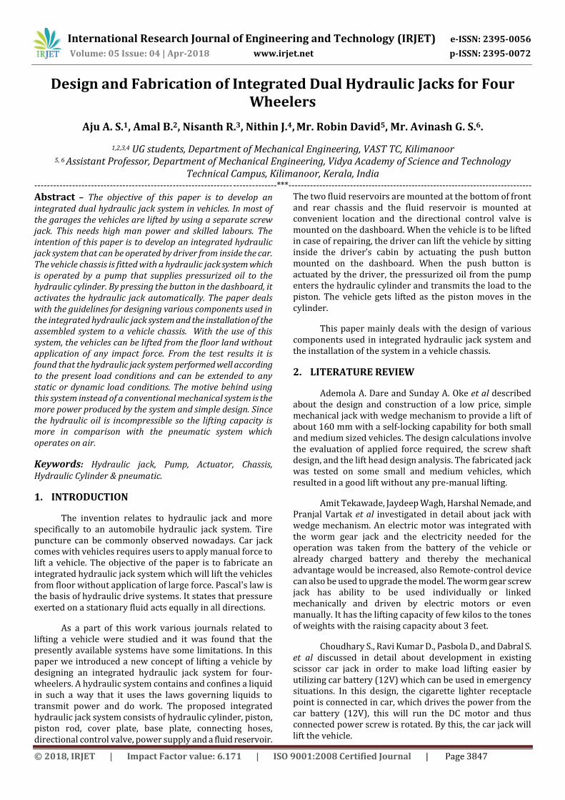
4.1 Working of Integrated Hydraulic jack
1. Hydraulic cylinder
2. Directional control valve
3. Fluid reservoir
4. Pump assembly
5. Battery
6. Connecting hoses
Fig. 4: Block diagram of Integrated Hydraulic Jacks
Figure 4 shows the block diagram showing the working of integrated hydraulic jack system for four- wheelers.
Two cylinders are mounted at the bottom of front and rear chassis at the center. These cylinders are connected to a fluid reservoir by connecting hoses through pump assembly and direction control valve. The pump assembly is actuated by 12-volt battery. When the vehicle is to lifted in case of repair, the hydraulic mechanism is actuated by pushing a push button located at the dashboard. When the switch is turned on the motor starts running which is powered by a battery already available in the car. The pump pressurizes the oil and transfer the pressurized oil to the fluid reservoir. This motor facilitates the flow of oil which is pressurized by the pump provided. Distribution of the pressurized oil is controlled by directional control valve. Separate control valves are used for actuating the front end and rear end fluid cylinders.
When the corresponding control valve is actuated and the oil from the fluid reservoir enters into the hydraulic cylinder, it exerts a certain amount of pressure on the plunger or the ram inside the cylinder. As the plunger moves downwards in the hydraulic cylinder, it transmits the load on the base plate connected at the bottom of the piston. After a definite travel of the plunger in the downward direction and once the base plate touches the ground it starts lifting the car. Once the car is lifted to a desired height the neutral position of control valve is actuated and the tires can be changed. When the tire is changed, the pressure in the hydraulic jack can be released by the directional control valve. Similarly, other side lifting can be done by using other control valve actuation.
4.2 Theoretical aspects of components used
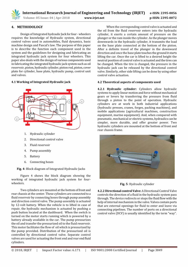
4.2.1 Hydraulic cylinder: Cylinders allow hydraulic systems to apply linear motion and force without mechanical gears or levers by transferring the pressure from fluid through a piston to the point of operation. Hydraulic cylinders are at work in both industrial applications (hydraulic presses, cranes, forges, packing machines), and mobile applications (agricultural machines, construction equipment, marine equipment). And, when compared with pneumatic, mechanical or electric systems, hydraulics can be simpler, more durable, and offer greater power. Two hydraulic cylinders are mounted at the bottom of front and rear chassis frame.
Fig. 5: Hydraulic cylinder
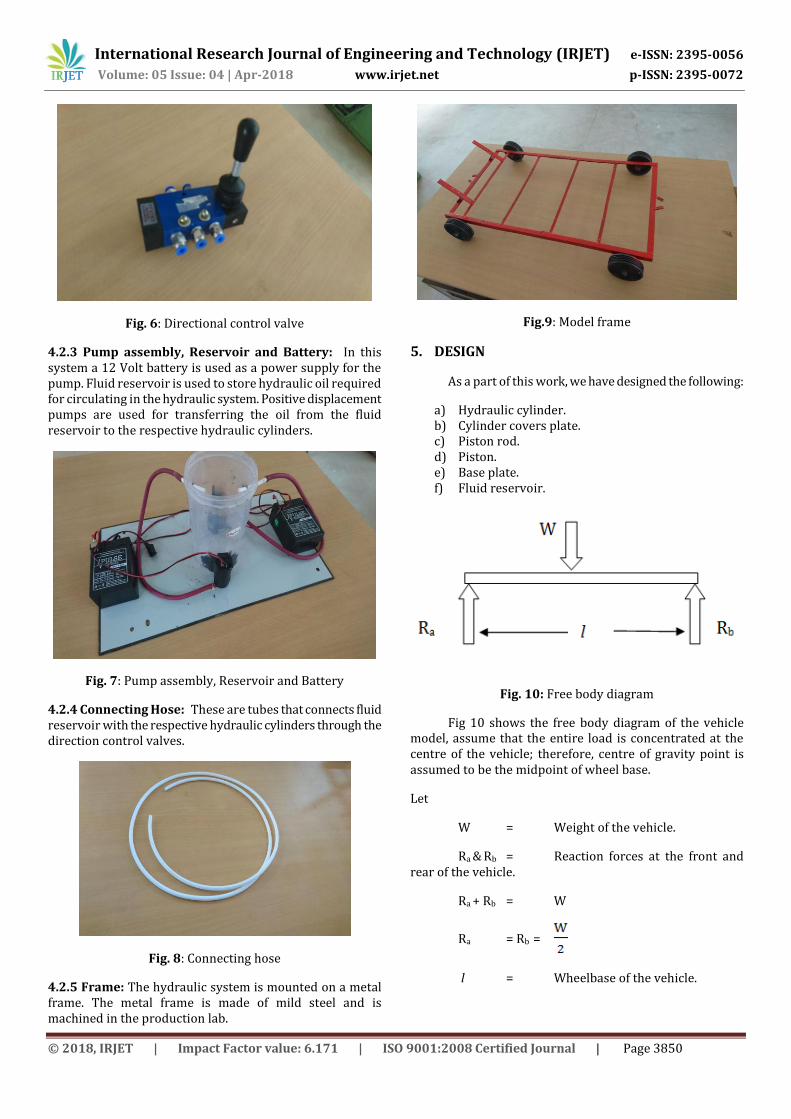
4.2.2 Directional control Valve: A Directional Control Valve controls the direction of a fluid in the hydraulic system pass through. The device redirects or stops the fluid flow with the help of internal mechanism in the valve. Valves contain ports that are external openings for fluid to enter and leave via connecting pipelines. The number of ports on a directional control valve (DCV) is usually identified by the term “way”.
International Research Journal of Engineering and Technology (IRJET) e-ISSN: 2395-0056
Volume: 05 Issue: 04 | Apr-2018 www.irjet.net p-ISSN: 2395-0072
© 2018, IRJET | Impact Factor value: 6.171 | ISO 9001:2008 Certified Journal | Page 3850
Fig. 6: Directional control valve
4.2.3 Pump assembly, Reservoir and Battery: In this system a 12 Volt battery is used as a power supply for the pump. Fluid reservoir is used to store hydraulic oil required for circulating in the hydraulic system. Positive displacement pumps are used for transferring the oil from the fluid reservoir to the respective hydraulic cylinders.
Fig. 7: Pump assembly, Reservoir and Battery
4.2.4 Connecting Hose: These are tubes that connects fluid reservoir with the respective hydraulic cylinders through the direction control valves.
Fig. 8: Connecting hose
4.2.5 Frame: The hydraulic system is mounted on a metal frame. The metal frame is made of mild steel and is machined in the production lab.
Fig.9: Model frame
5. DESIGN
As a part of this work, we have designed the following:
a) Hydraulic cylinder. b) Cylinder covers plate. c) Piston rod. d) Piston. e) Base plate. f) Fluid reservoir.
Fig. 10: Free body diagram
Fig 10 shows the free body diagram of the vehicle model, assume that the entire load is concentrated at the centre of the vehicle; therefore, centre of gravity point is assumed to be the midpoint of wheel base.
Let
W = Weight of the vehicle.
Ra & Rb = Reaction forces at the front and rear of the vehicle.
Ra + Rb = W
Ra = Rb =
l = Wheelbase of the vehicle.

International Research Journal of Engineering and Technology (IRJET) e-ISSN: 2395-0056
Volume: 05 Issue: 04 | Apr-2018 www.irjet.net p-ISSN: 2395-0072
© 2018, IRJET | Impact Factor value: 6.171 | ISO 9001:2008 Certified Journal | Page 3851
Fig.11: Hydraulic Cylinder
5.1 Design of Hydraulic Cylinder
Assume the cylinder is made up of mild steel and is mounted at the bottom of front and rear frame. It provides slide way to the plunger in order to build up the pressure.
Let
di = Inner diameter of the cylinder.
do = Outer diameter of the cylinder.
t = Thickness of the cylinder.
F = Load acting on the cylinder
=
P = Pressure acting inside the cylinder, which could be obtained from the specification of the pump.
P =
Where,
A = Inner area of the cylinder
= di 2
F =
Since the load and pressure acting on the cylinder are known, we can calculate the inner diameter of the cylinder.
Hoop stress, =
Where,
=
Thickness, t =
Thus the thickness of the hydraulic cylinder is obtained from the above equation and hence the outer diameter of the cylinder can be obtained.
Outer diameter of the cylinder, = di + 2t
5.2 Design of cylinder end plug (cover plate)
Cylinder end plug may be threaded, bolted, welded, or integral part of the cylinder shell. When the end plate is flat in shape, then its minimum thickness can be calculated by the following empirical formula.
tc = di
Where,
tc = Thickness of the cover plate.
di = Inside diameter of the cylinder (cm)
k = Empirical co-efficient = 0.162
P = Pressure inside the cylinder (kg/cm2)
= Permissible tensile stress for the material
of the Plate (kg/cm2)
5.3 Design of piston rod
Piston rod transfer the forces developed at piston to work the base plate. This force may be pushing or pulling. Piston rod is designed to transfer these forces along its central axis. It is not designed or expected to take any side bending load.
As the force acts through its central axis only, hence when the length of piston rod is shorter, then the cross section required to transfer force within the safe stress limit can be calculated using basic simple formula, such as
Force to be transfer, F = Cross sectional area Permissible
compressive or Tensile stress
Where,
F =
F = AP
Where,
F = load acting on the piston rod
AP = Cross sectional area of the piston
= dp2
dp = Diameter of the piston rod
= Permissible stress for the material.

International Research Journal of Engineering and Technology (IRJET) e-ISSN: 2395-0056
Volume: 05 Issue: 04 | Apr-2018 www.irjet.net p-ISSN: 2395-0072
© 2018, IRJET | Impact Factor value: 6.171 | ISO 9001:2008 Certified Journal | Page 3852
From the above equation, we can find out the diameter of the piston rod.
5.4 Design of piston
5.4.1 Diameter of the piston
Outside diameter of the piston is as per the inside diameter of the cylinder tube.
5.4.2 Thickness of the piston
Thickness of piston depends upon the load which has to be transfer. Under load, the piston may fail in two ways
a) Bending load b) Shear load
a) Thickness of piston subjected to bending
The oil under pressure applies uniform load on its complete projected area while piston is supported on its other side only at small annual area of piston rod. As there are large unsupported areas hence piston is supported to bending stress, which tends to bend piston and make it a dish like structure.
Fig.12: Piston subjected to bending
The following empirical formula can be used to finding out the thickness of piston,
= C
Where,
= Thickness of the piston
= Diameter of the piston = inside diameter
of cylinder
P = Fluid pressure
= Allowable tensile stress
C = Empirical constant
Empirical constant ‘C’ depends upon
Ratio of piston outside dia. And piston rod dia.
Type of piston and piston rod assembly value of ‘C’ can be selected from the design data book
b) Thickness of piston subjected to shear
Piston will be subjected to shear stress; hence the thickness of piston should be sufficient to resist the failure by shearing.
Fig.13: Piston subjected to shear
Minimum thickness of piston required to resist them could be calculated as follows:
Load on piston, F = Inside area working pressure of
cylinder Where,
F =
=
=
Where,
= Circumferential area resisting shear
= Permissible shear stress limit of material
of piston rod.
5.5 Design of base plate
Base plate is hinged at the bottom of the piston rod to transfer the load from the vehicle to the ground. Assume the load acting on the base plate as normal load.
Fig.14: Base plate
The base plate is subjected to compressive stress. Assume the length and breadth of base plate is known value.
Compressive stress =
W/2
International Research Journal of Engineering and Technology (IRJET) e-ISSN: 2395-0056
Volume: 05 Issue: 04 | Apr-2018 www.irjet.net p-ISSN: 2395-0072
© 2018, IRJET | Impact Factor value: 6.171 | ISO 9001:2008 Certified Journal | Page 3853
=
From the above equation, we can find out the value of
and select a suitable material to withstand the
compressive stress.
5.6 Design of fluid reservoir
We know the volume of the connecting tubes (hoses) and volume of the two-hydraulic cylinder.
Volume of oil circulated in the system
= volume of oil circulated in the hoses + 2(volume of cylinder)
= + 2 ( )
Where,
= Diameter of the hoses
= Length of the hoses used
=Inside diameter of cylinder
= Stoke length
But we take the volume of the oil in the reservoir, 33% greater than the volume of oil circulated in the system.
Assume the diameter of the cylinder is known and then we can calculate the length of the reservoir.
Volume of cylinder =
Volume of cylinder, V = + 2 ( ) +
0.33 + 2 ( ))
Where,
= Diameter of the reservoir
L = Length of the reservoir
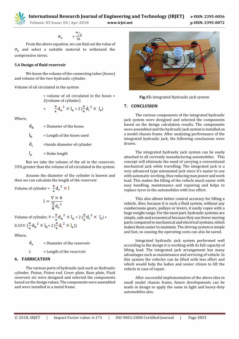
6. FABRICATION
The various parts of hydraulic jack such as Hydraulic cylinder, Piston, Piston rod, Cover plate, Base plate, Fluid reservoir etc were designed and selected the components based on the design values. The components were assembled and were installed in a metal frame.
Fig.15: Integrated Hydraulic jack system
7. CONCLUSION
The various components of the integrated hydraulic jack system were designed and selected the components based on the design calculation results. The components were assembled and the hydraulic jack system is installed on a model chassis frame. After analyzing performance of the integrated hydraulic jack, the following conclusions were drawn.
The integrated hydraulic jack system can be easily attached to all currently manufacturing automobiles. This concept will eliminate the need of carrying a conventional mechanical jack while travelling. The integrated jack is a very advanced type automated jack since it’s easier to use with automatic working, thus reducing man power and work load. This makes the lifting of the vehicle much easier with easy handling, maintenance and repairing and helps to replace tyres in the automobiles with less effort.
This also allows better control accuracy for lifting a vehicle. Also, because it is such a fluid system, without any cumbersome gears, pulleys or levers, it easily copes with a huge weight range. For the most part, hydraulic systems are simple, safe and economical because they use fewer moving parts compared to mechanical and electrical systems, which makes them easier to maintain. The driving system is simple and fast, so causing the operating costs can also be saved.
Integrated hydraulic jack system performed well according to the design it is working with its full capacity of lifting load. The integrated jack arrangement has many advantages such as maintenance and servicing of vehicle. In this system the vehicles can be lifted with less effort and which would help the ladies and senior citizen to lift the vehicle in case of repair.
After successful implementation of the above idea in small model chassis frame, future developments can be made in design to apply the same in light and heavy-duty automobiles also.

International Research Journal of Engineering and Technology (IRJET) e-ISSN: 2395-0056
Volume: 05 Issue: 04 | Apr-2018 www.irjet.net p-ISSN: 2395-0072
© 2018, IRJET | Impact Factor value: 6.171 | ISO 9001:2008 Certified Journal | Page 3854
ACKNOWLEDGEMENT
We express our extreme sense of gratitude to Dr. T. Mathavaraj Ravikumar, Head of the Department of Mechanical Engineering, for his gentle understanding, guidance and constant inspiration.
We wish to sincerely thank Mr. Bijeesh P., Project Coordinator, Mechanical Engineering Department, VAST TC, Kilimanoor for his immense support and motivation.
We are greatly indebted to our Project guide Mr. Robin David, Assistant Professor, Department of Mechanical Engineering, VAST TC for his keen interest, constant encouragement, constructive suggestions and inspiring guidance in every aspect of the work which has enabled us to complete this report successfully.
We are thankful to all the faculty members of Department of Mechanical Engineering for their help and cooperation. Special thanks to all our trade instructors, classmates and friends at VAST-TC who stood by our side during the endeavour.
REFERENCES
[1] Ademola A. Dare and Sunday A. Oke, Issue 31 March 2008, “Vehicle jack with wedge mechanism”; Maejo International Journal of Science and TechnologyISSN 1905-7873.
[2] Amit Tekawade, Jaydeep Wagh, Harshal Nemade, and Pranjal Vartak, Issue 02, 2015 “Worm Gear Jack for Scissor Lift”; International Journal for Scientific Research & Development. 03, ISSN (online): 2321-0613.
[3] Choudhary S., Ravi Kumar D., Pasbola D., and Dabral S Issue 04 (2016), “Development of Motorized Car Jack”; Journal of Applied Mechanical Engineering. Vol. 05, ISSN: 2168-9873 JAME.
[4] K.Sainath, Mohd Salahuddin, Mohd jibranbaig, Mdazam Ali Farooky, Mohammed Siddique Ahmed, Mohd Riyaz Uddin, Faraz Ur Rehman Azhar, and Md Shaffi. Issue 07 (July. 2014), “Design of Mechanical Hydraulic Jack”; IOSR Journal of Engineering. ISSN (e): 2250-3021, ISSN (p): 2278-8719Vol. 04, ||V1|| PP 15-28.
[5] Mithil R., Mijith C., Junufasin, Harilal N., Harikrishnan U., and Praveen C. P. Volume: 03 Issue: 02 / Feb-2016, “Fabrication of electro hydraulic jack”; International Research Journal of Engineering and Technology. e - ISSN: 2395 -0056, p - ISSN: 2395-0072.
[6] P. S. Borkar, S. V. Sontakke, R. R. Dorwe, A. B. Ganorkar, and S. P. Lokhande, Issue 03, 2015/ “Design of Pneumatic Operated Jack for Four-Wheelers”; International Journal for Scientific Research & Development. Vol. 3ISSN (online): 2321-0613.
BIOGRAPHIES
Mr. Aju A. S. pursuing Mechanical Engineering, 4th year 8th semester from Vidya Academy of Science and Technology, Technical Campus, Kilimanoor, Kerala, India
Mr. Amal B. pursuing Mechanical Engineering, 4th year 8th semester from Vidya Academy of Science and Technology, Technical Campus, Kilimanoor, Kerala, India
Mr. Nisanth R. pursuing Mechanical Engineering, 4th year 8th semester from Vidya Academy of Science and Technology, Technical Campus, Kilimanoor, Kerala, India
Mr. Nithin J. pursuing Mechanical Engineering, 4th year 8th semester from Vidya Academy of Science and Technology, Technical Campus, Kilimanoor, Kerala, India
Mr. Robin David presently working as Asst. Professor Vidya Academy of Science and Technology, Technical Campus, Kilimanoor, Kerala, India. He did his M. tech in Automobile Engineering from NIT Warangal and B. Tech from T.K.M College of Engineering, Kollam, Kerala. He has attended several workshops of Automobile Engineering and Machine design.
Mr. Avinash G. S. presently working as Assistant Professor in Vidya Academy of Science and Technology, Technical Campus, Kilimanoor, Kerala, India. He is having a total teaching experience of around 7 years in various renowned institutions. He has been handling Fluid Mechanics, Thermal Engineering, Gas Dynamics, and Propulsion Engineering. He presented a paper on 11th National and 1st International Conference on Technological Trends during November 25-27, 2010 held at College of Engineering, Trivandrum