hydraulic bottle jacks - kincrome _3.pdf · hydraulic bottle jacks 1 hydraulic bottle jacks k12150...
TRANSCRIPT
HYDRAULIC BOTTLE JACKS
1
HYDRAULIC BOTTLE JACKS
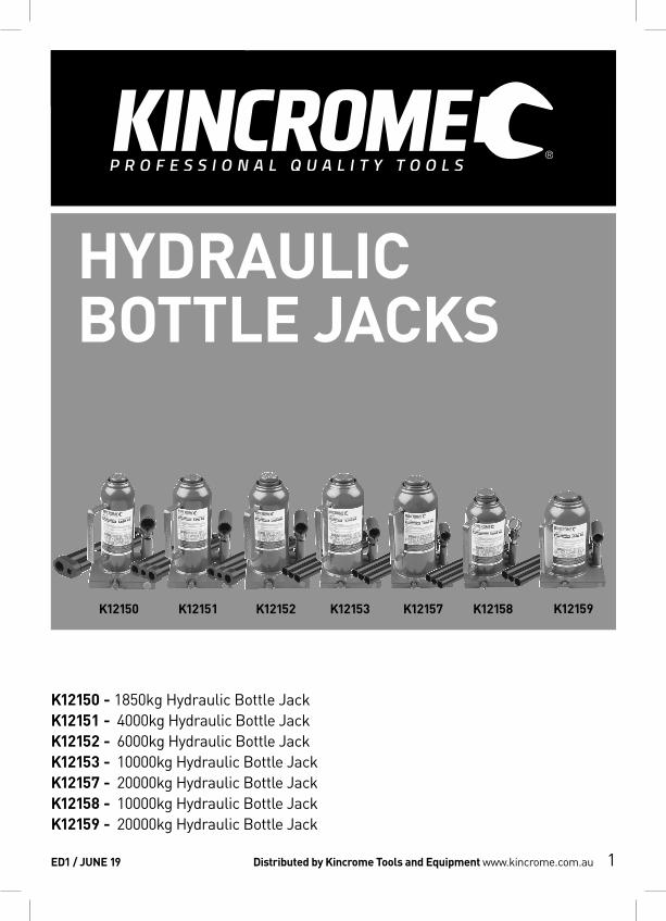
K12150 - 1850kg Hydraulic Bottle JackK12151 - 4000kg Hydraulic Bottle JackK12152 - 6000kg Hydraulic Bottle JackK12153 - 10000kg Hydraulic Bottle JackK12157 - 20000kg Hydraulic Bottle JackK12158 - 10000kg Hydraulic Bottle JackK12159 - 20000kg Hydraulic Bottle Jack
ED1 / JUNE 19 Distributed by Kincrome Tools and Equipment www.kincrome.com.au
K12150 K12151 K12152 K12153 K12157 K12158 K12159
HYDRAULIC BOTTLE JACKS
2
Owner’s Assembly and Operating ManualSPECIFICATIONS ......................................................................................................................................................2-3IMPORTANT SAFETY INFORMATION ......................................................................................................................... 4UNPACKING AND ASSEMBLING JACK ..................................................................................................................... 4 Unpacking Carton .................................................................................................................................................. 4 Handle - Handle Wrench ....................................................................................................................................... 4 Testing Handle Operation ...................................................................................................................................... 4 Purging Air From The Hydraulic System ............................................................................................................. 4OPERATING JACK ........................................................................................................................................................ 5 Preparing Work Area ............................................................................................................................................... 5 Lifting Vehicle ........................................................................................................................................................... 5 Working on Vehicle .................................................................................................................................................. 6 Lowering Vehicle ...................................................................................................................................................... 6MAINTENANCE AND STORAGE ................................................................................................................................. 6 Lubricating ............................................................................................................................................................... 6 Maintaining Oil Level ............................................................................................................................................... 6 Important Note: ....................................................................................................................................................... 6 Adding Oil ................................................................................................................................................................. 6 Replacing Oil ............................................................................................................................................................ 6 Cleaning .................................................................................................................................................................... 6 Storage ..................................................................................................................................................................... 6 Repairing Jack ......................................................................................................................................................... 6
SPECIFICATIONS
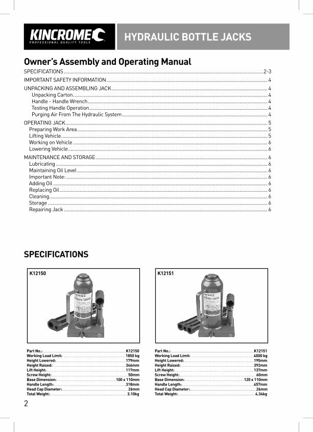
Part No.: .....................................................................................K12150Working Load Limit: .............................................................. 1850 kgHeight Lowered: .......................................................................179mmHeight Raised: ..........................................................................346mmLift Height: .................................................................................117mmScrew Height: ..............................................................................50mmBase Dimension: ............................................................100 x 110mmHandle Length: .........................................................................318mmHead Cap Diameter: ...................................................................26mmTotal Weight: ..............................................................................3.10kg
Part No.: .....................................................................................K12151Working Load Limit: .............................................................. 4000 kgHeight Lowered: .......................................................................195mmHeight Raised: ..........................................................................392mmLift Height: .................................................................................137mmScrew Height: ..............................................................................60mmBase Dimension: ............................................................120 x 110mmHandle Length: .........................................................................457mmHead Cap Diameter: ...................................................................26mmTotal Weight: ..............................................................................4.34kg
K12150 K12151
HYDRAULIC BOTTLE JACKS
3
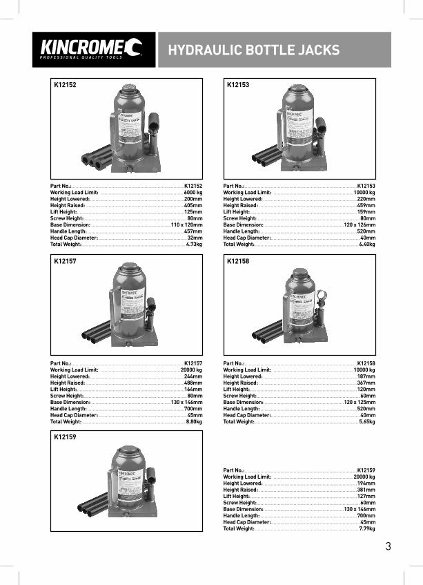
Part No.: .....................................................................................K12152Working Load Limit: .............................................................. 6000 kgHeight Lowered: .......................................................................200mmHeight Raised: ..........................................................................405mmLift Height: .................................................................................125mmScrew Height: ..............................................................................80mmBase Dimension: ............................................................110 x 120mmHandle Length: .........................................................................457mmHead Cap Diameter: ...................................................................32mmTotal Weight: ..............................................................................4.73kg
Part No.: .....................................................................................K12157Working Load Limit: ............................................................20000 kgHeight Lowered: .......................................................................244mmHeight Raised: ..........................................................................488mmLift Height: .................................................................................164mmScrew Height: ..............................................................................80mmBase Dimension: ............................................................130 x 146mmHandle Length: .........................................................................700mmHead Cap Diameter: ...................................................................45mmTotal Weight: ..............................................................................8.80kg
Part No.: .....................................................................................K12159Working Load Limit: ............................................................20000 kgHeight Lowered: .......................................................................194mmHeight Raised: ..........................................................................381mmLift Height: .................................................................................127mmScrew Height: ..............................................................................60mmBase Dimension: ............................................................130 x 146mmHandle Length: .........................................................................700mmHead Cap Diameter: ...................................................................45mmTotal Weight: ..............................................................................7.79kg
Part No.: .....................................................................................K12153Working Load Limit: ............................................................10000 kgHeight Lowered: .......................................................................220mmHeight Raised: ..........................................................................459mmLift Height: .................................................................................159mmScrew Height: ..............................................................................80mmBase Dimension: ............................................................120 x 126mmHandle Length: .........................................................................520mmHead Cap Diameter: ...................................................................40mmTotal Weight: ..............................................................................6.40kg
Part No.: .....................................................................................K12158Working Load Limit: ............................................................10000 kgHeight Lowered: .......................................................................187mmHeight Raised: ..........................................................................367mmLift Height: .................................................................................120mmScrew Height: ..............................................................................60mmBase Dimension: ............................................................120 x 125mmHandle Length: .........................................................................520mmHead Cap Diameter: ...................................................................40mmTotal Weight: ..............................................................................5.65kg
K12152
K12157
K12159
K12153
K12158
HYDRAULIC BOTTLE JACKS
4
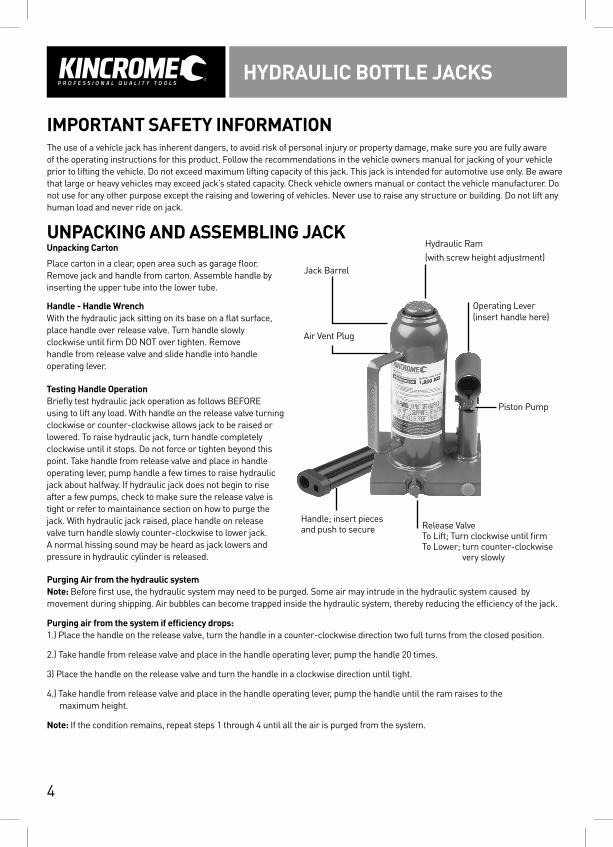
Jack Barrel
Operating Lever (insert handle here)
Piston Pump
Hydraulic Ram (with screw height adjustment)
Air Vent Plug
Handle; insert pieces and push to secure Release Valve
To Lift; Turn clockwise until firmTo Lower; turn counter-clockwise
very slowly
IMPORTANT SAFETY INFORMATIONThe use of a vehicle jack has inherent dangers, to avoid risk of personal injury or property damage, make sure you are fully aware of the operating instructions for this product. Follow the recommendations in the vehicle owners manual for jacking of your vehicle prior to lifting the vehicle. Do not exceed maximum lifting capacity of this jack. This jack is intended for automotive use only. Be aware that large or heavy vehicles may exceed jack’s stated capacity. Check vehicle owners manual or contact the vehicle manufacturer. Do not use for any other purpose except the raising and lowering of vehicles. Never use to raise any structure or building. Do not lift any human load and never ride on jack.
UNPACKING AND ASSEMBLING JACKUnpacking Carton
Place carton in a clear, open area such as garage floor. Remove jack and handle from carton. Assemble handle by inserting the upper tube into the lower tube.
Handle - Handle WrenchWith the hydraulic jack sitting on its base on a flat surface, place handle over release valve. Turn handle slowly clockwise until firm DO NOT over tighten. Remove handle from release valve and slide handle into handle operating lever.
Testing Handle OperationBriefly test hydraulic jack operation as follows BEFORE using to lift any load. With handle on the release valve turning clockwise or counter-clockwise allows jack to be raised or lowered. To raise hydraulic jack, turn handle completely clockwise until it stops. Do not force or tighten beyond this point. Take handle from release valve and place in handle operating lever, pump handle a few times to raise hydraulic jack about halfway. If hydraulic jack does not begin to rise after a few pumps, check to make sure the release valve is tight or refer to maintainance section on how to purge the jack. With hydraulic jack raised, place handle on release valve turn handle slowly counter-clockwise to lower jack. A normal hissing sound may be heard as jack lowers and pressure in hydraulic cylinder is released.
Purging Air from the hydraulic systemNote: Before first use, the hydraulic system may need to be purged. Some air may intrude in the hydraulic system caused by movement during shipping. Air bubbles can become trapped inside the hydraulic system, thereby reducing the efficiency of the jack.
Purging air from the system if efficiency drops:1.) Place the handle on the release valve, turn the handle in a counter-clockwise direction two full turns from the closed position.
2.) Take handle from release valve and place in the handle operating lever, pump the handle 20 times.
3) Place the handle on the release valve and turn the handle in a clockwise direction until tight.
4.) Take handle from release valve and place in the handle operating lever, pump the handle until the ram raises to the maximum height.
Note: If the condition remains, repeat steps 1 through 4 until all the air is purged from the system.
HYDRAULIC BOTTLE JACKS
5
OPERATING JACKPreparing Work AreaBefore using hydraulic jack to lift vehicle, it is important to prepare work area properly. Follow this procedure each time the jack is used to help prevent property damage and or serious injury.
1.) Thoroughly inspect hydraulic jack for damage or wear before each use. Briefly test operation of unloaded jack before using to lift any load. If hydraulic jack is damaged or is malfunctioning, DO NOT LIFT ANY LOAD until the problem is corrected.
2.) The vehicle manufacturer’s owner’s manual should be consulted prior to the lifting of the vehicle. It will advise safety precautions, jacking procedure, vehicle weight, recommended jack type, and location of jack support areas on vehicle. The working load limit of the hydraulic jacks is K12150 - 1850kg, K12151 - 4000kg, K12152 - 6000kg, K12153 - 10000kg, K12157 - 20000kg, K12158 - 10000kg, K12159 - 20000kg. NEVER EXCEED WORKING LOAD LIMIT OF JACK.
3.) Clear children and others from work area before moving or lifting vehicle. Another adult should be nearby for extra safety and assistance but must be clear of vehicle as it is moved or lifted. No person should remain in a vehicle that is being jacked. No person should enter a vehicle which is supported by a jack or by vehicle support stands. No person should lean into a vehicle which is supported by a jack or by vehicle support stands.
4.) No person should place any portion of their body under a vehicle that is supported by a jack.
5.) Clear obstructions from work area. Working in tight or cluttered work areas is dangerous.
6.) Be sure hydraulic jack and vehicle is on a solid level ground such as paved or concrete driveway or garage floor. The hydraulic jack should be used on level firm ground wherever possible. Uneven or sloped surfaces create hazardous working conditions and dangerously impede the function of the jack.
7.) With vehicle in proper position, set vehicle’s parking brake on or emergency brake and put gearshift in park (manual transmissions should be placed in lowest gear). TURN VEHICLE IGNITION OFF AND TO THE “LOCK” POSITION making sure steering wheel locks.
8.) It is recommended that the wheels of the vehicle be chocked. Do not rely on vehicle transmission or brakes to hold vehicle in position. Chock all wheels of vehicle not being lifted off the ground to prevent vehicle rolling. Using wedge-shaped blocks that tyre cannot roll over, position one chock tight against the tyre in both forward and reverse rolling paths.
9.) The load should be centrally located on the head cap. Off centre loads can be unstable.
10.) The hydraulic jack should be used for lifting and lowering only; the raised vehicle should be supported on vehicle support stands. Vehicle support stands (not included) will be needed to support vehicle once it is in raised position. Have vehicle support stands capable of supporting vehicle weight ready nearby for use. Read and understand jack stand manufacturer’s instructions and safety information before use and before lifting the vehicle with this jack.
11.) Plan location of jack beneath vehicle, making sure the hydraulic jack will be contacting only a jack support area of vehicle. Consult vehicle owner’s manual for location of jack support areas.
Lifting VehicleLifting a vehicle using a jack can be dangerous. Follow all instructions and precautions below. Do not lift any vehicle with its engine running or start any vehicle that is supported by jack or jack stands.
1.) With the hydraulic ram completely lowered, position the hydraulic jack beneath jack support area of vehicle. DO NOT MANOEUVRE JACK WITH HANDLE ON THE RELEASE VALVE
2.) Turn the handle clockwise until firm DO NOT over tighten. Remove handle from the release valve and slide the handle into operating lever.
3.) Inspect position of the head cap beneath support area, making sure it is centered and properly engaging support area.
4.) Continue pumping handle until vehicle is lifted to desired height. Pay attention to head cap position as vehicle is being raised to be sure there is no danger of support area slipping off or lifting from the head cap.
5.) Place jack stands under additional vehicle support areas.
6.) Place handle on release valve and twist the handle slowly counter-clockwise to lower jack.
HYDRAULIC BOTTLE JACKS
6
Working On Vehicle
Any vehicle being supported by a jack or jack stands creates a potentially hazardous working environment.
Do not move or roll a jack that is supporting a vehicle. Never place any part of your body beneath a vehicle supported by a jack. Be careful of forces applied to vehicle such as torque on a nut or bolt. These forces could cause vehicle to become unstable if jack stands are not properly placed. Do not turn ON the vehicle ignition or attempt to start any vehicle supported by jack or jack stands.
Lowering Vehicle
WARNING: Before lowering vehicle, be sure area under and near vehicle is clear of all persons and obstructions.1.) Re-position jack under same support area used to lift vehicle.
DO NOT MANOEUVRE JACK WITH HANDLE ON THE RELEASE VALVE
2.) Turn the handle clockwise until firm DO NOT over tighten. Remove handle from the release valve and slide the handle into handle operating lever
3.) Check to be sure head cap is centered under support area. Slowly pump handle to lift vehicle off from jack stands.
4.) Remove jack stands, setting them aside, well clear of vehicle.
5.) Place handle on release valve and with a firm grip on jack handle, SLOWLY turn handle counter-clockwise until jack just begins to lower.
6.) Carefully control speed of a descending vehicle. Lowering a vehicle too fast can cause property damage or injury.
MAINTENANCE AND STORAGELubricatingMoving parts on jack should be lubricated occasionally with a light machine oil to maintain efficient operation. Apply oil to joints on lift arm hinges, push rods, handle base, etc. Wipe away excess oil with soft cloth.
Maintaining Oil LevelImportant Note: When adding or replacing oil, always use a good grade Hydraulic Jack Oil, Kincrome K12400 Hydraulic oil is recommended. Avoid mixing types of oil, DO NOT use Brake Fluid, Alcohol, Glycerin, Detergent, Motor Oil or Dirty Oil, Improper fluid can cause serious internal damage to Jack.
Adding Oil:With head cap fully lowered lay jack on its side with air vent plug facing up, hold the jack vertical or use a rag or block to maintain a vertical position, remove air vent plug being careful not to allow dirt to enter system. Oil level should be approx 12 mm below valve hole. If low, add oil as needed then close air vent plug.
Replacing Oil:For better performance & longevity, replace oil supply once a year. To drain oil, open air vent plug and loosen the release valve by turning handle counter-clockwise. BE VERY CAREFUL not to permit dirt or foreign matter to get into the system. Invert jack over suitable container and allow oil to drain. Close release valve by turning handle clockwise, fill with Kincrome K12400 Hydraulic Jack Oil close air vent plug wipe away any spilt fluid. Test jack before lifting a load.
CleaningJack should be wiped clean with soft cloth only. Do not use gasoline, kerosene, or other such solvents or any abrasive cleanser as cleaning agents and solvents will cause deterioration of the hydraulic seals.
StorageBefore storage, turn the handle 1-1/2 turns counter-clockwise to release pressure in hydraulic cylinder. Leave handle in this position. Store jack level, in a clean environment preferably indoors, in a dry area to protect jack from moisture.
Repairing JackThere are no user serviceable parts except as outlined above. Only trained, licensed and certified repair personnel should attempt any repairs or replacing of parts. Any modifications to this jack, except those performed by the manufacturer, or their designee, will void all warranties both written and implied.
HYDRAULIC BOTTLE JACKS
7
NOTES
HYDRAULIC BOTTLE JACKS
Warranty given by Kincrome Australia Pty Ltd of 3 Lakeview Drive, Caribbean Park, Scoresby, Victoria (Tel 1300 657 528). If this product has materials or workmanship defects (other than defects caused by abnormal or non warranted use) you can , at your cost, send the product to place of purchase, an authorized Kincrome service agent or one of Kincrome’s addresses for repair or replacement. Your rights under this warranty are in addition to any other rights you have under the Australian Consumer Law or other applicable laws. Our goods come with guarantees that cannot be excluded under the Australian Consumer Law. You are entitled to a replacement or refund for a major failure and compensation for any other reasonably foreseeable loss or damage. You are also entitled to have the goods repaired or replaced if the goods fail to be of acceptable quality and the failure does not amount to a major failure. For further details please visit www.kincrome.com.au or call us
Distributed by Kincrome Tools and Equipmentwww.kincrome.com.au3 Lakeview Drive Scoresby VictoriaPhone: 1300 657 528