a one-year review of fukushima daiichi nuclear power … tepco today’s presentation i. accident...
TRANSCRIPT

TEPCO
A One-year Review of Fukushima Daiichi Nuclear Power Station
“Steps to Achieve Stabilization”
March 2012

1
TEPCO
Today’s Presentation
I. Accident Causes & Measures Taken(1) Earthquake Impact(2) Following the tsunami strike
II. Circulating Water Cooling
III. Mitigation of Radioactive Emission 36 ~ 41
IV. Preparation for Future Event(Countermeasures against earthquake and tsunami)
V. Misc. (Environmental improvement etc.)
42 ~ 47
30 ~ 35
48 ~ 52
2 ~ 29
Fukushima Daiichi Nuclear Power Station reached a cold shutdown condition and Step 2 of Roadmap towards Restoration was completed in December 2011. Now the mid and long term approach for decommissioning is ongoing. We hereby would like to explain the approach from the accident towards the stabilization so far.
- - - - -
- - - - -- - - - -
- - - - -
- - - - -

2TEPCO
I. Accident Causes & Measures Taken(1) Earthquake Impact

3TEPCO
Time: 2:46 pm on Fri, March 11, 2011.Place: Offshore Sanriku coast (northern latitude of 38 degrees, east longitude of 142.9 degrees),
24km in depth, Magnitude 9.0Intensity: Level 7 at Kurihara in Miyagi prefecture
Upper 6 at Naraha, Tomioka, Okuma, and Futaba in Fukushima pref.Lower 6 at Ishinomaki and Onagawa in Miyagi pref., Tokai in Ibaraki pref.
Scale of the Earthquake and Tsunamis
This was a massive M9.0 earthquake (fourth largest ever recorded in the world) that was caused by a coupling movement of several regions off-shore of Miyagi prefecture, the southern trench off-shore of Sanriku to the east, off-shore of Fukushima prefecture, and off-shore of Ibaraki prefecture.
震源
原子力発電所
Intensity Distribution of the earthquake The source area of the earthquake(Evaluated by Tokyo University)
Slip amount[m]
Wave source of the tsunami on March 11(Evaluated by TEPCO)
Epicenter
Fukushima Daiichi & Daini NPS
I. Accident Causes & Measures Taken

4TEPCO
4
Intensity of the earthquake at the power stations
Observation Point(The lowest basement of
reactor buildings)
Observed Data Maximum Response Accelerationagainst Basic Earthquake Ground
Motion (Gal)Maximum Response
Acceleration (gal)
Horizontal(N-S)
Horizontal(E-W) Vertical Horizontal
(N-S)Horizontal
(E-W) Vertical
Fukushima Daiichi
Unit 1 460* 447* 258* 487 489 412
Unit 2 348* 550* 302* 441 438 420
Unit 3 322* 507* 231* 449 441 429
Unit 4 281* 319* 200* 447 445 422
Unit 5 311* 548* 256* 452 452 427
Unit 6 298* 444* 244 445 448 415
FukushimaDaini
Unit 1 254 230* 305 434 434 512
Unit 2 243 196* 232* 428 429 504
Unit 3 277* 216* 208* 428 430 504
Unit 4 210* 205* 288* 415 415 504
In Fukushima Daiichi the observed data partially exceeded the maximum response acceleration with respect to the design-basis earthquake, however most data was below the baseline
Note) Standard ground motion Ss: Seismic motion that was newly established to evaluate seismic safety, taking into account the earthquakes, etc., that could occur around the power station, based on the revised seismic design review guidelines.
Status when the earthquake occurred: In operation, Shutdown
I. Accident Causes & Measures Taken
5TEPCO
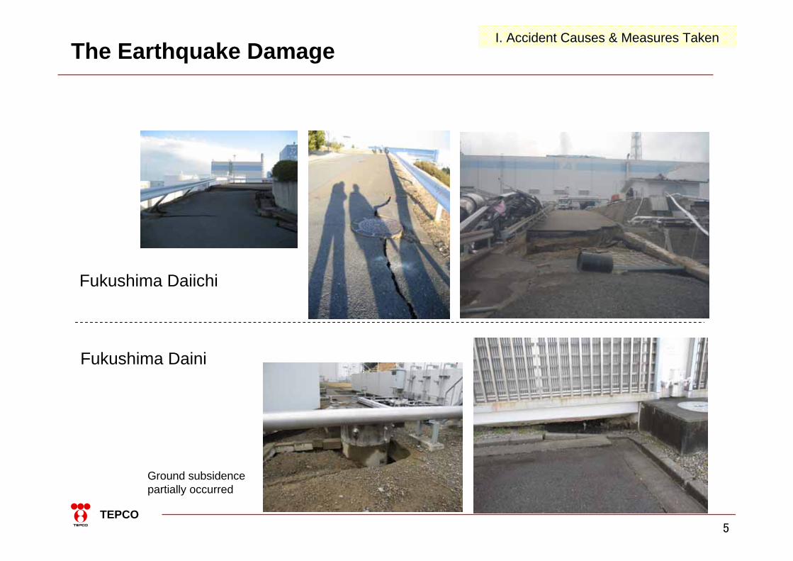
Fukushima Daiichi
Fukushima Daini
The Earthquake Damage
Ground subsidence partially occurred
I. Accident Causes & Measures Taken

6TEPCO
免震重要棟
事務本館
The tsunami height at Fukushima Daiichi Nuclear Power Station was far above the height (OP* + 5.4m ~ 6.1m) evaluated using the method of the Society of Civil Engineers.
0.0 1.0 2.0 3.0 4.0 5. 0 6.0 7.0 8.0 9.0 10.0(m)Inundation depth
※OP:Onahama Pile(0.727m below the average sea level in Tokyo Bay)
Maximum +13.1m (Approx. 51 minutes after the earthquake)
-10-5
05
1015
0 30 60 90 120 150 180 210 240Time (minutes)C
hang
e in
wat
er le
vel (
m)
Reproduction calculation results of the tsunami that hit the Fukushima Daiichi Nuclear Power Station (changes in water level near the tide station)
The calculation results reproducing the tsunami that struck Fukushima Daiichi Nuclear Power Station
Tsunami height at Fukushima DaiichiI. Accident Causes & Measures Taken

7TEPCO
Heavy Oil Tank (about 5.5 m high) was submerged by the tsunami, which was located at the level of OP +10 m.
Outdoor flooding conditions at Fukushima Daiichi Nuclear Power Station (Near the Unit 4 South-side Central Environmental Facility Process Main Building site height O.P.+10m, heavy oil tank height approximately 5.5m)
Outdoor Tsunami Flooding(Fukushima Daiichi)I. Accident Causes & Measures Taken

8TEPCO
Rubble inside the building
Tsunami Damage at Fukushima DaiichiI. Accident Causes & Measures Taken

9TEPCO
Washed Away Trees
Before March 11th
After March 11th
The Tsunami Damage at Fukushima DaiichiI. Accident Causes & Measures Taken

10TEPCO
0.0 1.0 2.0 3.0 4.0 5.0 6.0 7.0 8.0 9.0 10.0(m)
The calculation results reproducing the tsunami that struck Fukushima Daini Nuclear Power Station (inundation depth and inundated area )
Reproduction calculation results of the tsunami that hit the Fukushima Daini Nuclear Power Station (changes in water level near the tide station)
Maximum +9.1m (Approximately 48 minutes after the earthquake)
-10-5
05
1015
0 30 60 90 120 150 180 210 240Time (minutes) C
hang
e in
wat
er le
vel (
m)
Tsunami height at Fukushima DainiI. Accident Causes & Measures Taken

11TEPCO
[Layout]
(1)
(2)(3)
(1) Tsunami overflow
(2) Damage to the low area (Pickup area)
(3) No damage to Turbine Building of Units 3 and 4
Outside of Unit 1 emergency air blower room
Inside of Unit 1 emergency air blow room
Unit 1 emergency diesel control room (A)
Inundation through the louver of Unit 1 Reactor Annex Building
The Tsunami Damage at Fukushima DainiI. Accident Causes & Measures Taken

12TEPCO
Response of Fukushima Daiichi Units 1 to 3 (from Earthquake to Tsunami)
Although external power was lost due to the earthquake, the “Shutdown”, “Cool” and “Containment” operations along with the plant responses were properly implemented prior to the arrival of the tsunami.
地震発生~津波襲来までの対応(<止める>,<冷やす>,<閉じ込める>)Event Expected plant response
Unit 1
Unit 2
Unit 3
Units 1/2Main Control Room
Units 3/4Main Control Room
Main Administratio
n Building Earthquake occurrence<Shutting down>
-Scram
-Insertion of all control rods
-Reactor sub criticality check
○
○
○
○
○
○
○
○
○
-The operators waited for the shaking to subside then started normal scram operations
-An operator was assigned to each control panel, and condition-monitoring and operations were conducted in accordance with instructions from the supervisor
-While the Main Control Room became clouded with dust, like a smoke curtain, the operators waited for the shaking to subside and then started normal scram operations
-Evacuation and confirmation of safety
-Emergency disaster response personnel started responding at the anti-seismic building
External power loss <Cooling>
-Emergency diesel generator (D/G) startup
-Main steam isolation valve (MSIV) all closed
-Isolation condenser (IC) startup
-Reactor core isolation cooling system (RCIC) startup
-High pressure coolant injection system (HPCI) startup (if the water level decreases to L2)
○
○
○
-
-*
○
○
-
○
-*
○
○
-
○
-*
<Unit 1 >-Checked that the IC
automatically started up-As the reactor water
level was normal, IC was used to control reactor pressure rather than the HPCI
-Determined that one IC system was sufficient, and the reactor pressure was controlled using the A system.
<Unit 2 >-RCIC was manually
started up (manual startup was implemented again later)
<Unit 3 >-Checked that the D/G
started up and the emergency bus was charged
-RCIC was manually started up and confirmed that it was tripped due to reactor water level high↓-After the earthquake,
the safety of the operators was confirmed, and information regarding the earthquake and tsunami was disseminated by paging
*No startup, as there were no major decreases in water level
Status of Fukushima Daiichi Units 1 to 3Response between Earthquake and Tsunami (“Shutting down”& “Cooling down”)
I. Accident Causes & Measures Taken

13TEPCO
Immediate Post Earthquake Plant Conditions (Unit1 (1))
The scram was activated at 14:46 on March 11th, and all control rods were inserted at 14:47. Afterwards the reactor pressure was controlled within the approximate range of 6 ~ 7 MPa and there are no signs of any piping ruptures.
Alarm Recorder in Unit 1 (SCRAM)
(1)
(2)
(1) Automatic scram due to the earthquake (2) Total insertion of all control rods
(1)
(2)
(3)
(4)
(5)
0 2 4 6 8(MPa)
(1) Scram due to the earthquake (14:46)(2) Increase in pressure following closure of the main
steam isolation valve (3) Decrease in pressure following IC operation (14:52)(4) Increase in pressure following IC shutdown(5) Pressure fluctuation (estimated) due to the IC
*It is assumed that the tsunami struck just after 15:30. Recording is thought to have ended due to the effects of the tsunami.
Strip Chart in Unit 1 (Reactor Pressure)
※IC: Isolation Condenser
I. Accident Causes & Measures Taken
14TEPCO
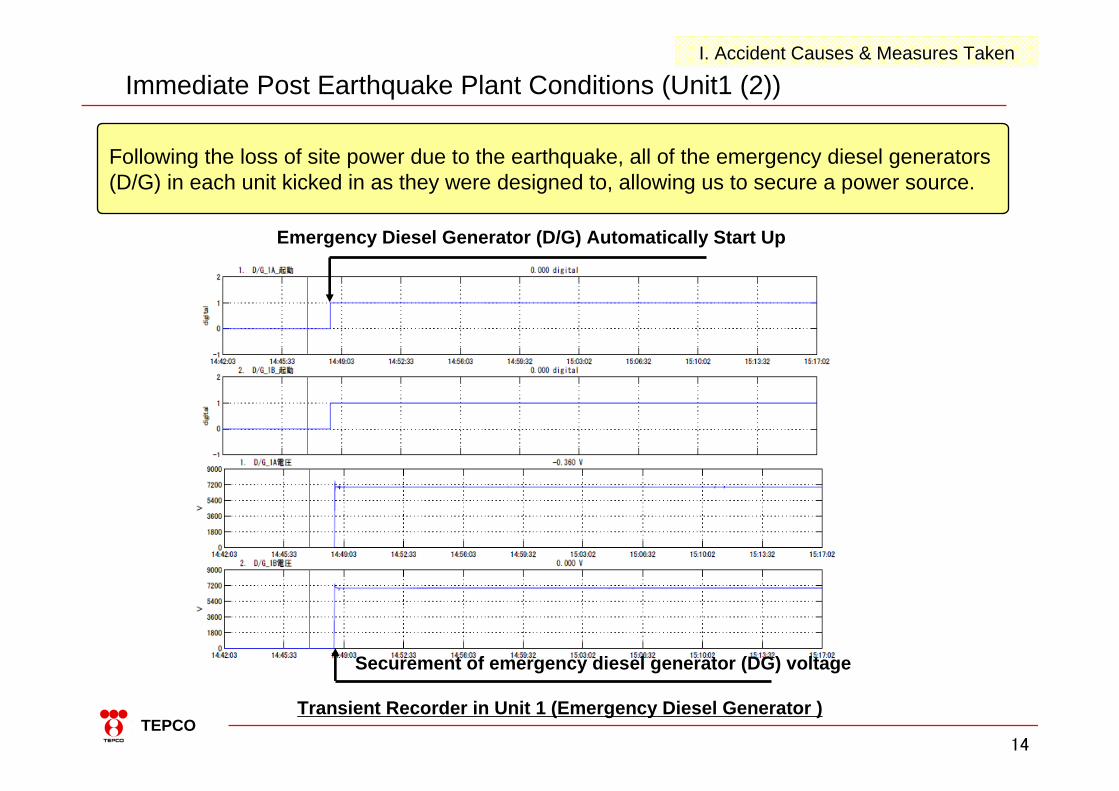
Following the loss of site power due to the earthquake, all of the emergency diesel generators (D/G) in each unit kicked in as they were designed to, allowing us to secure a power source.
Transient Recorder in Unit 1 (Emergency Diesel Generator )
Emergency Diesel Generator (D/G) Automatically Start Up
Securement of emergency diesel generator (DG) voltage
Immediate Post Earthquake Plant Conditions (Unit1 (2))I. Accident Causes & Measures Taken

15TEPCO
Results of the seismic assessments of Units 1-3 (there is no problem if the calculated value is smaller than the standard evaluation value) Unit:MPa(No unit for Reactor Building)
Plant Evaluation of the Earthquake’s Impact (1)It is estimated that the safety functions of the important safety-related equipment had been secured after the earthquake because the stress strain analysis with actual seismic records resulted below the design basis in all equipments.
**It is estimated that the safety functions had been secured in Units 4 to 6 of Fukushima Daiichi and all Units of Fukushima Daini as well according to the same analysis.
2 X 10-30.14 X 10-32 X 10-30.43 X 10-32 X 10-30.14 X 10-3Reactor Building
Structure & ComponentUnit 1 Unit 2 Unit 3
Calculated Value Criterion Value Calculated Value Criterion Value Calculated value Criterion Value
Reactor core support structure 103 196 122 300 100 300
Reactor pressure vessel 93 222 29 222 50 222
Main steam system piping 269 374 208 360 151 378
Reactor containment vessel 98 411 87 278 158 278
Shutdown cooling system
Pump 8 127
Piping 228 414
RHRPump 45 185 42 185
Piping 87 315 269 363
Others* - - - - 113 335
0
1
2
3
4
5
6
7
8
0 2 4
5F1F
CRF4F
4F3F
1FB1F
B1F
5FCRF
2F2F
3F
0
1
2
3
4
5
6
7
8
0 2 4
1FCRF3FB1F
4F
5FCRFB1F
4F2F 3F1F5F
2F4F3F
2F1FB1F
4F3F
2F1F
B1F
0
1
2
3
4
5
6
7
8
0 2 4Shearing strain ( X 10-3)
She
arin
g st
ress
(N/m
m2 )
Unit 1 (East-West direction) Unit 3 (East-West direction)Unit 2 (East-West direction)
Criterion Value Criterion Value Criterion Value* Other listed equipment subject to evaluation: (Unit 3) High pressure coolant injection system steam pipe
Shearing strain ( X 10-3) Shearing strain ( X 10-3)
She
arin
g st
ress
(N/m
m2 )
She
arin
g st
ress
(N/m
m2 )
I. Accident Causes & Measures Taken

16TEPCO
16
Visual check results of Fukushima Daiichi Unit 5
Taken August 18-August 30, 2011
1stfloor
Basem
ent
2ndfloor
Turbine Building
Basement
4th floor
3rd floor
2nd floor
Reactor Building Turbine Building
Inside the containment
vessel
1stfloor
Reactor Building
Main steam isolation valve ・No equipment abnormality in terms of external appearance
Safety relief valve ・No equipment abnormalityin terms of external
appearance
Inside the pedestal・No equipment abnormality in terms of external appearance
Reactor pressure vessel support skirt・Although there is rust on the foundation bolt, there are no equipment abnormalities in terms of external appearance
Core spray system pump ・No equipment abnormalityin terms of external appearance・Retained water on the floor・ Signs of leakage on the wall penetration in the same area
Control rod drive water pump・No equipment abnormalityin terms of external appearance
Residual Heat Removal System pump・No equipment abnormalityin terms of external appearance・Retained water on the floor
Main steam isolation valve ・No equipment abnormality in terms of external appearance
Reactor Auxiliary Cooling Water SystemHeat exchanger・ No equipment abnormality in terms of external appearance
Fuel Pool Cooling system pump・Although some signs of corrosion (rust development) is found in both units, there are no equipment abnormalities in terms of external appearance(A) In operation, (B) On standby
Standby liquid control system pump ・No equipment abnormality in terms of external appearance
1st floor 2nd floor 3rd floor 4th floor
Emergency diesel generator 5A,5B・No equipment abnormality in terms of external appearance
Moisture separator Insulation and support came loose
Pipe around the moisture separatorNo3 Damage to the small diameter pipe that branches off from the moisture separator drain pipe
High-pressure turbine ・There are some cracks on the front
standard foundation bolt
No damage confirmedNo damage confirmed to important
safety-related equipments
Plant Evaluation of the Earthquake’s Impact (2)I. Accident Causes & Measures Taken

17TEPCO
X-53
X-53
OP:12490m
工業用内視鏡
工業用内視鏡
CRDレール
:撮影方向
小口径配管もしくは電線管と思われる構造物
配管配管
サポートサポート
原子炉格納容器内壁
付着物付着物
天天
地地
天天
地地
(2012.1.19)
No damage was confirmed to the small-diameter piping inside the PCV according to the video observation in Unit 2 of Fukushima Daiichi
Piping
Support
up
down
up
downCRD rail
Industrial endoscope
Industrial endoscope
Structure of small-diameter piping or electric conduit
PCV inside wall
scaffolding
Observation direction
Plant Evaluation of the Earthquake’s Impact (3)I. Accident Causes & Measures Taken

18TEPCO
18
Isolation condenser
IC(A) condensed water return pipe IC(A) condensed water return pipe MO-1301-3B
IC(A) condensed water return pipe IC(B) condensed water return pipe IC(B) condensed water return pipe
Isolation condenser has two systems: A system and B system
MO-1301-2
MO-1301-3
IC(A) IC(B) IC inlet steam pipe
IC inlet steam pipe
MO-1301-2A position meter
MO-1301-2B position meter
MO-1301-10MO-1301-10A position meterMO-1301-10B position meter
IC(A) Water level gauge IC(B) Water level gauge
From the Fire Protection System/
Make-up Water System
Water level gauge IC condensed water return pipe IC condensed water return pipe
MO-1301-4
MO-1301-1
PLR- B
原子炉圧力容器
PLR- A PLR- B
原子炉圧力容器
Reactor pressure vessel
PLR- A
4th floor
3rd floor
2nd floor
Note) The valve position display is for the standby status
No damage was confirmed to the body and piping of Unit 1 IC as a result of visual observation where possible.
Plant Evaluation of the Earthquake’s Impact (4), Unit 1 ICI. Accident Causes & Measures Taken

19TEPCO
0
2
4
6
8
10
3/120:00
3/126:00
3/1212:00
3/1218:00
3/130:00
3/136:00
3/1312:00
3/1318:00
3/140:00
日時
原子炉圧力
(MP
a[ab
s])
RPV圧力(解析)
実機計測値
HPCI停止RCIC停止
SRV開HPCI起動
復水貯蔵タンク
原子炉圧力容器
MO
主蒸気管
MO
FIC
MO
流量制御
タービンタービン
MO
MO
MO
水源切替ラインMO
圧力抑制室
MO
HO
HO
AO
給水系
タービン止め弁
加減弁
格納容器
MO
最小流量バイパス弁
ミニマムフローライン
注入ライン
蒸気管
MO
テストライン
MO
テストバイパス弁
Although the piping rupture of HPCI in Unit 3 was a concern considering the reactor pressure decrease, no damage was confirmed by the operator who investigated in the field after HPCI had been brought to a stop. The reactor pressure decrease during HPCI operation is due to its continuous water injection.
HPCI system diagram(Emergency cooling water injection system to the reactor)
RPV
Pre
ssur
e (M
Pa[a
bs])
・The reactor pressure decreased after HPCIstart-up and maintained near 1MPa.・After HPCI stopped,
the reactor pressure increased.・The decreased reactor
pressure is simulated with operator’s flow control by analysis.
stopstart stop
open
pressure (analysis)measured value
PCV
S/C
ST
RPV
MS line
MSV
CV
Steam line
Feed
wat
er
Injection line
Minimum flow line
Minimum flow bypass valve
FC
Tes
t lin
e
CST Test bypass valve
Water source switch line
Plant Evaluation of the Earthquake’s Impact (5), Unit 4 HPCII. Accident Causes & Measures Taken

20TEPCO
Although the external power at Fukushima Daiichi was lost due to the earthquake, it is estimated that the power supply was secured by emergency diesel generators and the plant was in a condition to be properly managed after the earthquake.
(1) “Shutdown”, “Cool” and “Containment” operations along with plant response and parameters were properly implemented.
(2) Estimated that the safety functions of important safety-related equipment were secured according to an analysis of observed seismic records.
(3) No damage to the important safety equipment was confirmed after Unit 5 investigation etc.(Damage was hardly observed even in the functions of the low seismic-level equipment.)
Summary (Impact of the earthquake)I. Accident Causes & Measures Taken

21TEPCO
I. Accident Causes & Measures Taken(2) Following the tsunami strike

22TEPCO
22
吸気ルーバーからの進入
Breakwater Sea water pump
Emergency D/Gair supply louver
Turbine Building
Site heightO.P.+ 10m
(Units 1-4* 1)
Site height O.P.+4m
*1 The site height of Units 5 & 6 is O.P.+13m
O.P.0 m
Inundation height Units 1-4 : O.P.+ 11.5~ 15. 5mUnits 5 & : O.P.+ 13~ 14.5m
* 2 The Unit 6 D/G is placed in a separate building such as the Reactor Building
Building entrance
Equipment hatch ・・
非常用
D/G
Emergency D/GPower panel
* 2 Makeup pump
Basement floor
Flooding Path into the Main Building
Emergency diesel generators and electrical equipment rooms were flooded through (1) entrance of the building, (2) equipment hatch, (3) inlet air louver of emergency D/G, (4) trench and duct (cable penetrations etc.), and lost its functions.Emergency sea water pumps outdoor were submerged and lost its function.
D/G:Diesel GeneratorOP:Onahama Pile(0.727m below the average sea level in Tokyo Bay)
I. Accident Causes & Measures Taken
23TEPCO
23
For transmission For transmission
Yonom
oriline Y
onomoriline
D/GD/GD/GD/GD/G
5A H 6A 6B5B
Okum
a line
Okum
a line
Okum
a line
Okum
a line
D/G D/G D/G D/GD/G
D/G D/G D/G
4B 4A 3B 3A 2B 2A 1B 1A
2L1L
1L2L3L4L
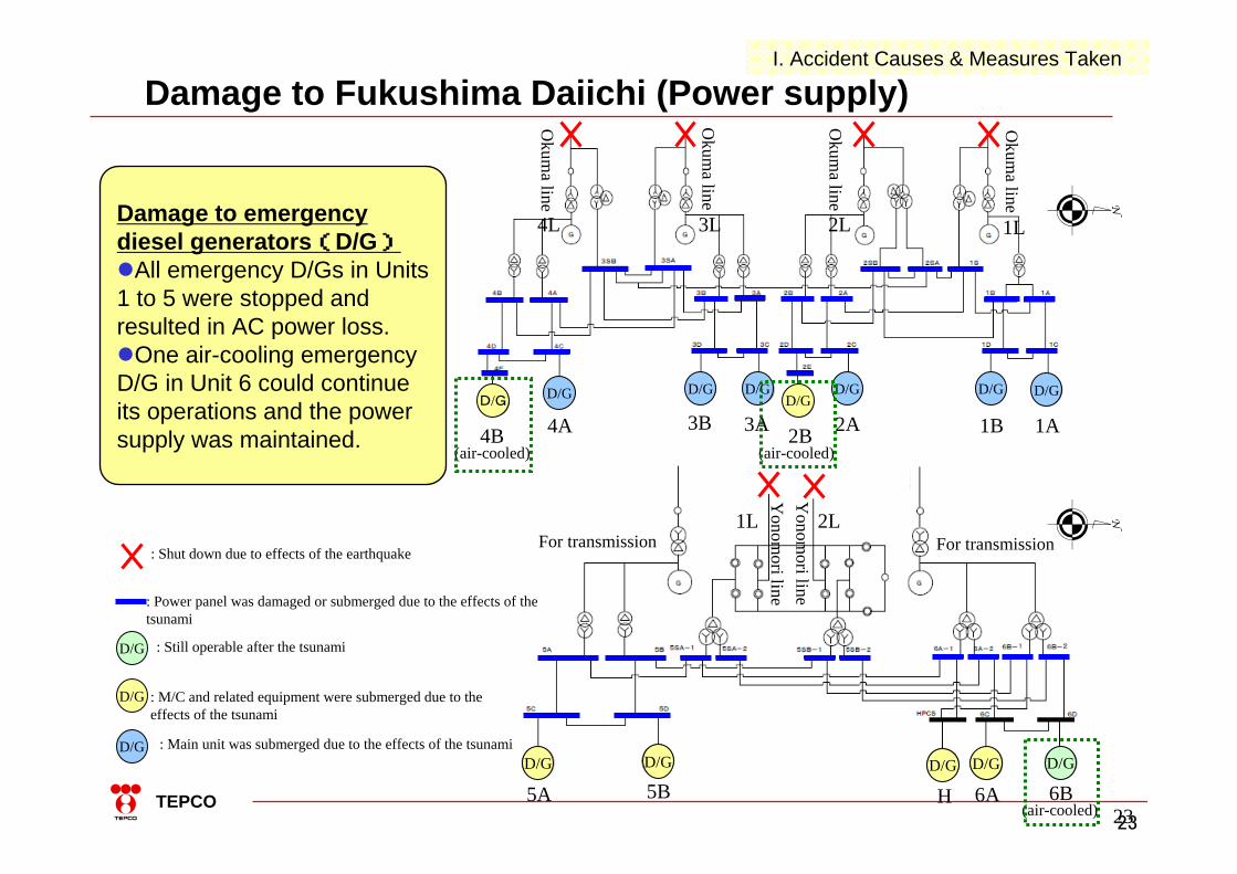
: Shut down due to effects of the earthquake
: Main unit was submerged due to the effects of the tsunami D/G
: Still operable after the tsunami D/G
: Power panel was damaged or submerged due to the effects of thetsunami
: M/C and related equipment were submerged due to the effects of the tsunami
D/G
(air-cooled) (air-cooled)
(air-cooled)
Damage to emergency diesel generators(D/G)All emergency D/Gs in Units 1 to 5 were stopped and resulted in AC power loss.One air-cooling emergency D/G in Unit 6 could continue its operations and the power supply was maintained.
Damage to Fukushima Daiichi (Power supply)I. Accident Causes & Measures Taken

24TEPCO
Damage to Fukushima Daiichi and Daini(Power supply)
Fukushima Daiichi Fukushima Daini
1F-1 1F-2 1F-3 1F-4 1F-5 1F-6 2F-1 2F-2 2F-3 2F-4
External power supply × × ○
Emergency diesel generator(*: Air-cooling)
ABH
××-
×△*-
××-
×△*-
△△-
△○*△
×××
△△△
△○○
△△○
Emergency M/C × × × × × ○ 1/3 ○ ○ ○
Normal M/C × × × × × × ○ ○ ○ ○
Emergency P/C( ) : number of systems under maintenance
× 2/3 × 1/2(1)
× ○ 1/4 2/4 3/4 2/4
Normal P/C( ) : number of systems under maintenance
× 2/4 × 1/1(1)
2/7 × ○ ○ ○ ○
DC power supply × × ○ × × ○ ○ 3/4 ○ ○ ○
Sea water pump × × × × × × × × 1/2 ×
→
A serious situation occurred at Units 1 to 4 of Fukushima Daiichi when the external power, the function of emergency diesel generators with M/C and P/C, and DC power supply along with the heat removal function of sea water pumps were lost.
○:Available (or number of available systems)△:Not available due to submerged M/C etc. although D/G not flooded×:Not available -:No system
I. Accident Causes & Measures Taken

25TEPCO
Response after tsunami arrival (Fukushima Daiichi Units 1 to 3)
Date Unit 1 Unit 2 Unit 3
11
12
13
14
Around 15:30 tsunami arrival
Sea water injection
MonitoringInstrument Monitoring
InstrumentRCICoperationAnalysis
Core damage
MonitoringInstrument
Venting preparationstarted
Lineup completed D/W pressure decrease
11:01 Hydrogen explosion
Flexible response・Low pressure injection:through Fire Protection system(FP)with fire trucks・Venting:with temporary battery and air compressor due to power loss・Monitoring Instrument:out of service due to power loss but restored by temporary battery
Venting preparation started
Venting completion not confirmed
Fresh waterinjection
RCICoperation
HPCIoperation
During loss of cooling water injection functions due to AC and DC power loss, alternative water injection into the reactors was conducted using fire trucks and PCV venting was conducted by improvised manual operations using temporary equipment.
ICoperation
IC:Isolation condenserRCIC:Reactor Core
Isolation CoolingHPCI:High Pressure Core
InjectionD/W:Dry Well(Air side)
Fire trucks
Venting operation startedD/W pressure decrease
Fire trucksSea water injection
AnalysisCore damage
AnalysisCore damageFire trucks
Sea water injection
Fresh waterinjection
15:36 Hydrogen explosion
Sea water injection
I. Accident Causes & Measures Taken

26TEPCO
Response to Fukushima Daiichi Unit 1(Water injection to Reactor)
Debris and scattered gates or cars on the roads were removed by two heavy equipment to gain access to the water injection inlet.
It took time to find the water injection inlet after the debris had been removed.
As the radiation dose had been increased after fresh water injection started, the operation was once suspended and restarted after the full-face masks were prepared.
Improvised water injection was conducted with fire trucks prepared as a countermeasure after the Chuetsu-oki earthquake because the power supply was lost and diesel-driven fire pumps were not available. In addition, the water source had to be promptly switched from the fire protection water tank (fresh water) to sea water.
××
×
×○→
*: Approval from the Prime Minister (the director-general of emergency response headquarters) was not confirmed for sea water injection and TEPCO headquarters instructed the site superintendent to stop temporarily. As it was deemed necessary, the site superintendent continued sea water injection.
Water injection was prepared with one fire truck available
For sea water injection, three fire trucks including two provided by Kashiwazaki-Kariwa NPP and Self-Defense Forces were lined up in series utilizing the Unit 3 backwashing valve pit as a water source.
Hoses for sea water injection became unavailable after the reactor building exploded before completion of the installation of the hoses..
Sea water injection was started after injured staff were rescued and hoses were collected from the outdoor fire hydrant and then lined up again.*
The site superintendent instructed sea water injection when fresh water was about to be exhausted
Fire trucks FP
Filtered water tank
CSTMotor-driven pump
Motor-driven pump
diesel-driven pump
MUWC
I. Accident Causes & Measures Taken

27TEPCO
72AO
ボンベ
210MO ラプチャーディスク
排気筒
1AO
ボンベ
閉
閉
83AO
閉
閉90AO
0.549MPabsで破壊
RPV
D/W
RPVRPV
D/W
IA
IA
D/W最高使用圧力0.528MPabs
ベント実施圧力0.954MPabs
電磁弁
電磁弁
213AO
(25%開)
R/B B1F
Manual openingoperation successful
AO
AO
Manual opening operation abandoned
due to high dose
AO
AOMO
MO Ruptured disc
Broke at 0.549MPabs
Closed
Closed
ClosedSolenoid valve
Solenoid valve
Cylinder
Cylinder
D/W maximum operating pressure
Closed
Stack
Venting pressure
S/C vent valve
(AO valve)
Access route to S/C vent valve (AO valve)
The valve could not be operated from the main control room due to the loss of power supply and air pressure, thus it was decided to open it manually in the field.
The second team entered the Torus room (R/B B1F), but the valve was located at the opposite side from the entrance.
Since the radiation meter exceeded its measurable limit, the operators had to give up and return.
Manual opening of S/C venting valve (small AO valve)
Decided to give up the manual operation for venting and to Decided to give up the manual operation for venting and to choose another methodchoose another method((to connect a portable compressor to connect a portable compressor and generator etc.and generator etc.))
The valve could not be operated from the main control room due to power losses, thus it was decided to open it manuallyin the field.
The first team reached the PCV venting valve (MO valve) located on the 2nd floor of R/B and manually opened the valve in the field.
Manual opening of PCV venting valve (MO valve)
Opening of PCV venting valve (MO valve)Opening of PCV venting valve (MO valve) completedcompleted
Normally venting can be operated from the main control room, but due to the power loss, actions outside of the normal procedures had to be taken.
MO valve:Motor-Operated valve
AO valve:Air-Operated valve
PCV: Primary Containment Vessel
S/C:Suppression Chamber
Response to Fukushima Daiichi Unit 1 (PCV venting)I. Accident Causes & Measures Taken

28TEPCO
Field Operation Difficulty
Subsidence of roads etc.Dangerous to walk in, especially at night
ObstaclesDetours to avoid fire truck hoses etc. After the explosion, debris and damaged fire trucks became obstacles.
Temporary battery for instrumentsUtilized temporary battery etc. for the power source of the instruments
Vice operation manager during monitoringMonitoring with a full-face mask on in complete darkness.
Field operation difficulties increased due to the aftershocks, the risk of tsunamis, and obstacles from the tsunami debris interrupted the outdoor work and also lighting was lost due to AC power loss.
I. Accident Causes & Measures Taken

29TEPCO
Cause of Hydrogen Explosion
The evaluation of the hydrogen explosion at Fukushima Daiichi is as follows.Unit 1 & 3: Hydrogen generated from the damaged reactor fuels without cooling function accumulated in the PCV, leaked into the Reactor Building and then exploded.(It is estimated that inert gas (nitrogen) was properly inserted and thus the explosion inside the PCV was
able to be avoided.)Unit 4: Hydrogen leaked and accumulated from the neighboring Unit 3 through the Standby Gas Treatment System (SGTS) piping while it was venting and then it exploded.Unit 2: It is estimated that the air ventilation inside the building was stimulated when the blow-out panel on the top floor burst open due to the explosion of Unit 1 and thus an explosion was avoided.
Units 1 & 3 Image of leakage path
Opening the Unit 2 blowout panel
I. Accident Causes & Measures Taken

30TEPCO
II. Circulating Water Cooling

31TEPCO
Establishment of Circulating Water Cooling System
・High-level contaminated water spilled out to the Unit 2 intake. (2011.4.2)・Contaminated water accumulated in the Central Radioactive Waste Treatment
Building and was released into the ocean.(2011.4.4)・Contaminated water spilled out through a pit near the Unit 3 intake.(2011.5.11)
- Prevent the increase of accumulated water volume- Reuse of contaminated water for injection into the reactors after treatment
Situation in the pit near Unit 3 intake
II. Circulating Water Cooling
Increase of contaminated water accumulated in the basement of the Reactor and Turbine Buildings.- Injected water into the reactors leaked through the damaged RPV and PCV into the basement of the buildings.
Before Circulating Water Cooling

32TEPCO
Storage TanksCirculation
Desalination system-Reverse Osmosis-Evaporator
Secondary Cesium adsorption Apparatus
(SARRY)
Decontamination Apparatus(AREVA)
「Removal of radioactive materials」
“Desalination”
Reactor Building
Turbine Building
Process Main BuildingHigh-temperature Incineration Building
Cesium adsorption Apparatus(KURION)
Overview of Circulating Water Cooling (Water processing)
“Circulated cooling water injection” has been established to reuse the contaminated water in the buildings (accumulated water) for injection into the reactors (since 2011/6/27.)
2nd Cs adsorptionDecontaminationReverse OsmosisEvaporator Cs adsorption
II. Circulating Water Cooling

33TEPCO
Achievement of “Cold Shutdown Conditions”
Temperatures of RPV bottom Temperatures inside PCV
Temperatures of the RPV bottom and inside PCV are stable below 100 degree Celsius via the Circulating Water Cooling.
0
50
100
150
200
7/17 8/21 9/25 10/30 12/4 1/8 2/12
℃
Unit 2
Unit 1
Unit 3
0
50
100
150
200
7/17 8/21 9/25 10/30 12/4 1/8 2/12
℃
Unit 2
Unit 1
Unit 3
II. Circulating Water Cooling

34TEPCO
Level of Accumulated Water Maintained as Targeted
Management of accumulated water in the Turbine Building (T/B)
The level of accumulated water is being maintained so that the water does not overflow to the outside of the buildings with heavy rain and the long-term shutdown of the processing facilities.
OP:Onahama Pile(0.727m below the average sea level in Tokyo Bay)
Target level
Water level
Water level Water levelUnit 2 Unit 3Water Processing started
Secondary Cesium adsorption apparatus started
II. Circulating Water Cooling

35TEPCO
Preventing the Spread of Contamination to the Ocean
Image of the impermeable wall
Overview Cross-section
To prevent the spread of contamination to the ocean in case the underground water becomes contaminated, an impermeable wall is under construction in front of Units 1 to 4. It is scheduled to be completed within the 2014 fiscal year.
Impermeable wall
Permeable layer
Permeable layer
Impermeable layer
Impermeable layer
Impermeable wall
Existing revetment
Landfill
II. Circulating Water Cooling
36TEPCO
III. Mitigation of Radioactive emission

37TEPCO
Radiation Dose Rate of Monitoring Posts etc.
Maximum at Main Gate 11930Sv/h↓
At Main Gate (as of Nov.) approx. 27Sv/h (approx. 1/400)
III. Mitigation of Radioactive Emission
The radiation dose rate was rapidly increased at each point after the accident, but since then it has been in a stable declining trend and is now approximately the background level at each point.
Dos
e ra
te
Main gate (portable)
Near main gate (car)
South of office (portable)Near MP-4 (car)
West gate (portable)Near west gate (car)

38TEPCO
0
2
4
6
8
10
12
7月 8月 9月 10月 11月 12月 1月 2月
放出量(億ベクレル/時)
1~3号機格納容器からの放射性物質(セシウム)の一時間当たりの放出量
Mitigation of Radioactivity Particle Release
Radiation dose at the site boundary0.02mSv/year (as of Feb.)(limit for the public determined by law: 1m Sv/year)
Radioactive particle (Cesium) release per hour from Units 1 to 3
-What is Bq?-Unit for radioactivity. 1 Bq is the radioactivity where 1 nucleus decays per second with radioactive ray. (Source: Nuclear Disaster Prevention Glossary released by MEXT)
Approximately 1/80,000,000 the amount at the time of the accident
about 10million Bq/hour
(about 1×10⁷ Bq/hour)
Radioactive particle (Cesium) release per hour from Units 1 to 3R
elea
se (0
.1 b
illion
Bq/
hour
)
July August September October November December January February
III. Mitigation of Radioactive Emission

39TEPCO
Radioactivity concentration inside the power station(1) In front of Environment Building
Cs-134(検出)
Cs-137(検出)
I-131(検出)
マスク着用基準(Cs-134)
法令に定める濃度限度(Cs-134)
【2】環境管理棟前
1.0E-07
1.0E-06
1.0E-05
1.0E-04
1.0E-03
1.0E-02
H23.5.1
H23.6.2
H23.6.5
H23.6.8
H23.6.20
H23.7.4
H23.7.18
H23.8.1
H23.8.15
H23.8.29
H23.9.12
H23.9.29
H23.10.17
H23.10.31
H23.11.14
H23.11.28
H24.1.1
(Bq/cm3) 【13】免震重要棟前
1.0E-07
1.0E-06
1.0E-05
1.0E-04
1.0E-03
1.0E-02
H23.5.14
H23.6.4
H23.6.7
H23.6.15
H23.6.29
H23.7.13
H23.7.27
H23.8.10
H23.8.24
H23.9.7
H23.9.14
H23.9.29
H23.10.19
H23.11.2
H23.11.16
H23.11.30
H24.1.1
(Bq/cm3)
正門
西門
(1)
(2) In front of Main Anti-earthquake building
免震重要棟
Radioactivity has exhibited a declining trend since the accident, and is now below the legal limit or the criteria requiring that masks be worn. Thus, the management of full-face masks and Tybeks has been simplified since March 1st, 2012.
West gate
Main gate
Criteria for mask
Legal limit
III. Mitigation of Radioactive Emission
(2)

40TEPCO
Southern outlet, Radioactivity (Bq/L)
1.0E-01
1.0E+00
1.0E+01
1.0E+02
1.0E+03
1.0E+04
1.0E+05
1.0E+06
3/11 4/10 5/10 6/9 7/9 8/8 9/7 10/7 11/6 12/6 1/5 2/4 3/5
1.0E-01
1.0E+00
1.0E+01
1.0E+02
1.0E+03
1.0E+04
1.0E+05
1.0E+06
3/11 4/10 5/10 6/9 7/9 8/8 9/7 10/7 11/6 12/6 1/5 2/4 3/5
1.0E-01
1.0E+00
1.0E+01
1.0E+02
1.0E+03
1.0E+04
1.0E+05
1.0E+06
3/11 4/10 5/10 6/9 7/9 8/8 9/7 10/7 11/6 12/6 1/5 2/4 3/5
Radioactivity concentration in the ocean (Onshore and offshore)
● Northern outlet
● Southern outlet
●
15km off shore
15km off shore, Radioactivity (Bq/L)
*Scale Vertical: 1E-1 ~ 1E+6 Horizontal: 2011/3/11 ~ 2012/3/5 *Legend I-131 Cs-134 Cs-137
decreased below 1/1,000 (Cs-137)
Not detected after July
Northern outlet, Radioactivity (Bq/L)
In a declining trend since the accident, and now below a noticeable level.*Notice level:Legal limit I-131…40 Cs-134…60 Cs-137…90 (Bq/L)
decreased below 1/1,000 (Cs-137)
III. Mitigation of Radioactive Emission

41TEPCO
380
6.31.2
0
100
200
300
400
2011年3月15日14時頃測定開始後最大値
2011年3月31日12時頃(局所排風機及び鉛遮蔽の設置後)
2012年3月5日10時頃
(μSv/h)
Radioactive dose rate at the Anti-seismic building
Entrance of anti-earthquake building(Entry management unit house)
Entrance of anti-seismic building(from indoor)
Radioactivity dose levels has been decreased due to environmental improvements inside the anti-seismic building.
2nd floor of anti-earthquake buildingemergency response room
2011.3.15 around 14:00Maximum after measurement started
2011.3.31 around 12:00after installation of local ventilation equipment and lead shielding
Dose rate at Emergency response room on 2nd floor of anti-seismic building(Maximum point in the room)
2012.3.5 around 10:00
III. Mitigation of Radioactive Emission

42TEPCO
IV. Preparations for Future Event(Countermeasures against the earthquake and tsunami)

43TEPCO
Result of seismic analysis of Units 1 to 4 Unit: N/A
0.17 X 10⁻³
calculation
Unit 4
4 X 10⁻³
criteria
Unit 1 Unit 2 Unit 3
calculation criteria calculation criteria calculation criteriaReactor Buildings
0.12 X 10⁻³ 4 X 10⁻³ 0.17 X 10⁻³ 4 X 10⁻³ 0.14 X 10⁻³ 4 X 10⁻³
IV. Future preparation
The seismic resistance of reactor buildings was analyzed against future large earthquakes based on the seismic ground motion according to the seismic design review standards and the actual building damages, although Units 1, 3 and 4 were damaged due to the hydrogen explosion. As a result, it has been confirmed that there is enough margin to satisfy the criteria and the reactor buildings have a sufficient seismic safety margin against future large earthquakes.
(Unit 1)
0
1
2
3
4
5
6
7
8
0 2 4
せん断ひずみ(×10-3)
せん断応力度(N/mm2)
B1F
1F 3F
1F 3F 2F
4F B1F
2F 4F
Maximum response on shear skeleton curve
(Unit 4)(Unit 2)
0
1
2
3
4
5
6
7
8
0 2 4
せん断ひずみ(×10-3)
せん断応力度(N/mm2)
1F 3F B1F
1F 3F 2F
B1F 4F
4F 2F
(Unit 3)(Ss-1, NS direction) (Ss-2, NS direction)(Ss-1, EW direction) (Ss-1, EW direction)
0
1
2
3
4
5
6
7
8
0 1 2 3 4
せん断ひずみ(×10-3)
せん断応力度(N/mm2)
5FCRFB1F
5F1FCRF3F2FB1F4F
1F2F4F3F
* It is estimated that the safety is secured in Units 5 and 6 ofFukushima Daiichi as a result of the same analysis.
She
ar s
tress
She
ar s
tress
She
ar s
tress
She
ar s
tress
Shear strain Shear strain Shear strain Shear strain
Plant Evaluation of the Earthquake’s Impact

44TEPCO
Reinforcement of Unit 4 Reactor Building
コンクリート壁
使用済燃料プール
鋼製支柱
コンクリート壁
鋼製支柱
<コンクリート打設後>
<コンクリート打設前>
Steel support structure (2011.6.20)
Concrete placement (2011.7.21)
Inside Spent Fuel Pool(2012.2.9)
Fuel
Before concrete placement
After concrete placement
Steel support structure
Steel support structure
Concrete wallConcrete wall
Spent Fuel Pool
IV. Future preparation

45TEPCO
Installation of Temporary Coastal Barrier
Unit 4
Location of temporary coastal barrier
Sea area(4m high)
Unit 3Main building area
(10m high)
Temporary coastal barrier was installed as a countermeasure against tsunamis in case of a large aftershock of a magnitude 8 level.(completed in June 30th 2011)
Installation work of temporary coastal barrier
IV. Future preparation
46TEPCO
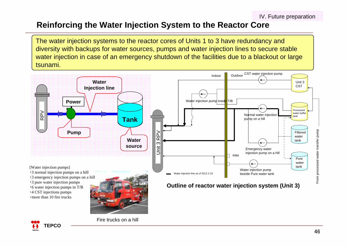
Reinforcing the Water Injection System to the Reactor Core
The water injection systems to the reactor cores of Units 1 to 3 have redundancy and diversity with backups for water sources, pumps and water injection lines to secure stable water injection in case of an emergency shutdown of the facilities due to a blackout or large tsunami.
Fire trucks on a hill
[Water injection pumps]・3 normal injection pumps on a hill・3 emergency injection pumps on a hill・3 pure water injection pumps ・6 water injection pumps in T/B・4 CST injections pumps・more than 10 fire trucks
Outline of reactor water injection system (Unit 3)
送水口
常用高台炉注水ポンプ
非常用高台炉注水ポンプ
純水タンク脇炉注水ポンプ
純水
タンク
タービン建屋内炉注水ポンプ
CST炉注水ポンプ
処理水
バッファ
タンク
建屋内 屋外
3号機
復水貯蔵
タンク
ろ過水
タンク
処理水移送ポンプより
3号機
原子炉圧力容器
:H23.2.23時点での炉注水ラインH24.2.23時点での炉注水ライン
Power
Water source
Water Injection line
Tank
原子炉圧力容器
Pump
RPV
Uni
t 3 R
PV
OutdoorIndoor CST water injection pump
Unit 3 CST
Water injection pump inside T/B
Normal water injection pump on a hill
Emergency water injection pump on a hill
Processed water buffer tank
Filtered water tank
Pure water tank
From
pro
cess
ed w
ater
tran
sfer
pum
p
Water injection pump beside Pure water tank
Inlet
Water injection line as of 2012.2.23
IV. Future preparation

47TEPCO
M/C5A
Tohoku Electric66kV Tepco Nuclear
Line275kV Okuma line 2L
Yonomori line 2L(Futaba line 2L)
Yonomori line 1L (Futaba line 1L)
Shared M/C(1B)
Shared M/C(1A)
M/C5C
M/C6A
M/C6C
M/C5B
M/C5D
M/C6B
M/C6D
Anti-earthquake Building
Okuma line 3L*1Okuma line 4L *2
*2
Mini-Clad
BackupM/C
Shared M/C(2B)
Process Bldg.M/C
D/G
EvaporatorM/C
Shared M/C(2A)
*1
Temp. 3/4M/C A
Process Bldg.Backup M/C D/G D/G D/G D/G
Completed at the end of March
CommonD/G(A)M/C
M/C partially switched
Switch
Reinforcement of Power Supply
Power supply has redundancy so that the electricity can be received either by the external power through the transmission lines or the diesel generators at the site. The external power has 5 transmission lines available.(End of March: 6 lines) 4 diesel generators are available (end of March: 5 D/G.) In addition, 2 power supply vehicles have been deployed in the case of a blackout.
Power supply vehicle
Power supply vehicle
IV. Future preparation
48TEPCO
V. Misc. (Environmental improvements etc.)

49TEPCO
Enhancement of the Medical Care System
Date:2011.9.6Venue:Fukushima Daiichi Emergency medical room at Units 5 & 6
Service building 1st floor. (Front) medical space (Back) patient space
Date:2011.9.6Venue:Fukushima Daiichi Emergency medical room at Units 5 & 6
Service building 1st floor. (Right) doctor (Left) nurse
V. Misc.
Date:2011.9.6Venue:Fukushima Daiichi Emergency medical room at Units 5 & 6
Service building 1st floor. (Right) doctor (Left) nurse
Date:2011.9.5Venue:Fukushima Daiichi Entrance of Units 5 & 6 Service building
1st floor. Training for screening and decontamination for a patient
50TEPCO
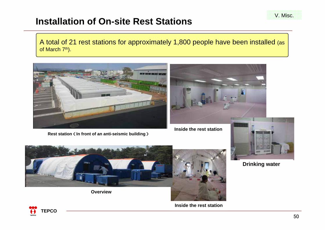
Installation of On-site Rest Stations
Overview
A total of 21 rest stations for approximately 1,800 people have been installed (as of March 7th).
Rest station(In front of an anti-seismic building)Inside the rest station
Drinking water
Inside the rest station
V. Misc.
51TEPCO
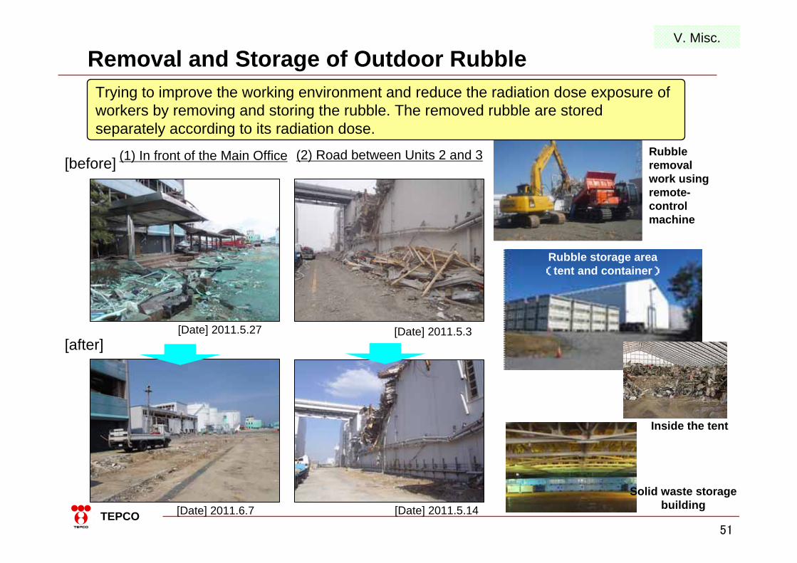
(1) In front of the Main Office[before]
[Date] 2011.5.27[after]
[Date] 2011.6.7
(2) Road between Units 2 and 3
[Date] 2011.5.3
[Date] 2011.5.14
Removal and Storage of Outdoor Rubble
Rubble removal work using remote-control machine
Trying to improve the working environment and reduce the radiation dose exposure of workers by removing and storing the rubble. The removed rubble are stored separately according to its radiation dose.
Rubble storage area(tent and container)
Inside the tent
Solid waste storage building
V. Misc.

52TEPCO
Reactor Building Rubble Removal Work
Unit 3 2012.2.21Removal of Unit 4 crane garter 2012.3.5
To prepare for fuel removal from the Spent Fuel Pools, the scattered debris above the Units 3 & 4 reactor buildings are now being removed.
Unit 3 Rubble removal work above the reactor building is being carried out by the remote-control heavy equipment on the surrounding gantry or the ground to reduce the radiation dose of workers.
Unit 4 Rubble removal work is carried out by manned heavy equipments on the ground since the radiation dose around the working area is relatively low.
Remote-control room
Camera on top
Optical cable
Opt
ical
cab
le
Unit 3 Reactor Building
GantryGantry
Camera
Remote-control heavy equipment
Remote-control large crane
Camera
Remote-control heavy equipment
Communication station
V. Misc.

53TEPCO
End

54TEPCO
Long and Mid term Roadmap
Will proceed with the long and mid term roadmap which indicates the schedule of main on-site works and R&D until the completion of decommissioning.
・Completion of fuel debris removal (20 ~ 25 years later)・Completion of decommissioning (30 ~ 40 years later)・Implementation of radioactive waste treatment and disposal
・Completion of fuel removal from Spent Fuel Pools of all Units・Completion of preparation for decontamination inside buildings, PCV repair & flooding and fuel debris removal. Start of fuel debris removal (within 10 years as a target)・Stable and continuous reactor cooling・Completion of accumulated water processing・Continuous R&D for radioactive waste treatment and disposal. Start of R&D for decommissioning
・Start of fuel removal from Spent Fuel Pools(Unit 4, within 2 years)・Reduction of the radioactivity from additional release from the power station and radioactive waste (water processing by-product and debris etc.), with effective radiation dose at the site boundary below 1 mSv/year.・Continuous safety and reliability improvement of reactor cooling and accumulated water processing.・Start of technology development and decontamination work for fuel debris removal・Start of R&D for radioactive waste treatment and disposal
Until decommissioning completed (30 ~ 40years later)
Until start of fuel debris removal (within 10 years)
Until start of fuel removal from Spent Fuel Pools (within 2 years)
<Stabilization>- Cold shutdown condition- Effective mitigation of release
Step1, 2 Phase 1 Phase 2 Phase 3
Systematic staff training and allocation, motivation improvement, and efforts to secure safety (Continue)
Present (Step 2 completed) Within 2 years Within 10 years 30~40 years later2011.12.16
* Debris:Pellet and cladding tube melted then solidified

TEPCO
We deeply apologize for the trouble and anxiety that has arisen due to the Fukushima Daiichi Nuclear Power Station Accident.
We will continue with our efforts to maintain stable cooling conditions and work towards the decommissioning of the reactors per the long-and-mid term roadmap while always keeping in mind that safety must be our top priority.