us 20020029207a1 (19) united states (12) patent ... · scheduling slice&dice flow control print...
TRANSCRIPT

(19) United States US 20020029207A1
(12) Patent Application Publication (10) Pub. No.: US 2002/0029207 A1 Bakalash et al. (43) Pub. Date: Mar. 7, 2002
(54) DATA AGGREGATION SERVER FOR MANAGING AMULTI-DIMENSIONAL DATABASE AND DATABASE MANAGEMENT SYSTEM HAVING DATA AGGREGATION SERVER INTEGRATED THEREN
(75) Inventors: Reuven Bakalash, Beer Sheva (IL); Guy Shaked, Shdema (IL); Joseph Caspi, Herzlyia (IL)
Correspondence Address: Thomas J. Perkowski, Esq., PC Soundview Plaza 1266 East Main Street Stamford, CT 06902 (US)
(73) Assignee: HyperRoll, Inc.
(21) Appl. No.: 09/796,098
(22) Filed: Feb. 28, 2001
Related U.S. Application Data
(63) Continuation-in-part of application No. 09/514,611, filed on Feb. 28, 2000.
Publication Classification
(57) ABSTRACT
Improved method of and apparatus for aggregating data elements in multidimensional databases (MDDB). In one aspect of the present invention, the apparatus is realized in the form of a high-performance Stand-alone (i.e. external) aggregation Server which can be plugged-into conventional OLAP Systems to achieve Significant improments in System performance. In accordance with the principles of the present invention, the Stand-alone aggregation Server con tains a Scalable MDDB and a high-performance aggregation engine that are integrated into the modular architecture of the aggregation Server. The Stand-alone aggregation Server of the present invention can uniformly distribute data ele ments among a plurality of processors, for balanced loading and processing, and therefore is highly Scalable. The Stand alone aggregation Server of the present invention can be used to realize (i) an improved MDDB for supporting on-line analytical processing (OLAP) operations, (ii) an improved Internet URL Directory for supporting on-line information searching operations by Web-enabled client machines, as well as (iii) diverse types of MDDB-based Systems for Supporting real-time control of processes in response to complex States of information reflected in the MDDB. In another aspect of the present invention, the apparatus is integrated within a database management Sys tem (DBMS). The improved DBMS can be used to realize achieving a significant increase in System performance (e.g. deceased access/search time), user flexibility and ease of use. The improved DBMS system of the present invention can be used to realize an improved Data Warehouse for Supporting on-line analytical processing (OLAP) operations
(51) Int. Cl." ....................................................... G06F 7700 or to realize an improved informational database System, (52) U.S. Cl. ............................................. 707/1; 707/104.1 operational database System, or the like.
On-line
East Data Warehouse s OAP g (RDBMS) OLAP Engine Interface
Systems (ROLAP) (OLTP)
Compiled information
Ratios Grids Parallel Data Query Ranks Graphs Backup & recovery Transforms Maps Parallel Loading Dynamic Consolidation Alerts Parallel Indexing Complex Filtering Drill-doWn Hashing Forecasts Data Pivot Data partitioning Query Governing Data Surf
Scheduling Slice&Dice Flow Control Print Pre-Aggregate inferencing Denormalization Support Table Partitioning and Joins

Mar. 7, 2002. Sheet 1 of 50 US 2002/0029207 A1 Patent Application Publication

US 2002/0029207 A1
V LVCI
| | | | J | | I |
|(EGCIW) ESVE VIVO
! { | | | | †
Mar. 7, 2002. Sheet 2 of 50 Patent Application Publication


Patent Application Publication Mar. 7, 2002 Sheet 4 of 50 US 2002/0029207 A1

Patent Application Publication Mar. 7, 2002. Sheet 5 of 50
Array structure of a multidimensional variable
D2EO
D21 D1
. RP O
D2E2 2
D2E3 s Cr 1O1 D23 .
DO
2 3 4 5 O 1
| | | | | | | | | | | | | | |
| | | |
Fig. 2C
US 2002/0029207 A1

Patent Application Publication Mar. 7, 2002 Sheet 6 of 50 US 2002/0029207 A1
Page # Page of physical records
Fig. 2D

Mar. 7, 2002. Sheet 7 of 50 US 2002/0029207 A1 Patent Application Publication
| Ø, / | /
e?ep opseq | ESnOHBHVM

US 2002/0029207 A1 Mar. 7, 2002 Sheet 8 of 50 Patent Application Publication

Mar. 7, 2002. Sheet 9 of 50 US 2002/0029207 A1 Patent Application Publication
|

US 2002/0029207 A1 Mar. 7, 2002. Sheet 10 of 50 Patent Application Publication
ÇOÇ (61-) Á?oueJe?? EWLL go Kouednooo ?e?edS
(ZCI) ENIL 0C]
?OT
ZOG (61-) [I] .... [] [] [] [] [] [] [] [] º?ºd [] .... [] [] [] [] sºlººM [] .... [] [] sinuow

Patent Application Publication Mar. 7, 2002 Sheet 11 of 50 US 2002/0029207 A1
i
C O
D O C CD O (s n
he at a us so a a s r. so on to east

US 2002/0029207 A1 Mar. 7, 2002. Sheet 12 of 50
E5DVILNEHORJEld
EZIS ESVÆV/LV/C)]
E||WHL NOLLVTT OTVO-ERJd C]NV
CIVOT V LVCI
%00),
Patent Application Publication
US 2002/0029207 A1 Mar. 7, 2002. Sheet 13 of 50 Patent Application Publication
‘CINE LNOH- In? ‘LEBHSCÍVEHdS ’9”E) NO]] \/€)E\{00\/ -JO SLNEITO HEHLO


US 2002/0029207 A1 Mar. 7, 2002. Sheet 15 of 50 Patent Application Publication
ETTìCJOW (S)EÐVHOLS
'O9 (5) | -!

US 2002/0029207 A1 Mar. 7, 2002. Sheet 16 of 50 Patent Application Publication
C19 (5) | -!
V LVCI ELVIT OTVO
ETETTO ILSETYDERYH

S_LNEHTO CHVTO
Mar. 7, 2002. Sheet 17 of 50
(SNOLIVOITddw ‘CINE LNOJ-- In? ‘LBHHSGWEHdS '9'E)
Patent Application Publication

US 2002/0029207 A1 Mar. 7, 2002. Sheet 18 of 50 Patent Application Publication
SI NEITO
ESTIOHERH\//\/\ \/ LVCI

US 2002/0029207 A1 Mar. 7, 2002. Sheet 19 of 50 Patent Application Publication
Z v

Patent Application Publication Mar. 7, 2002. Sheet 20 of 50 US 2002/0029207 A1
CC O)
CD
L
N N. N
N

Sheet 21 of 50 US 2002/0029207 A1 Patent Application Publication Mar. 7, 2002
86 "5) | H
? NOISNE WICI NI NO]] \/€)=|}}5)§)\/ CJELLETCHWOO Zé· ||||| /^((\|)/O/

Patent Application Publication Mar. 7, 2002 Sheet 22 of 50 US 2002/0029207 A1
2 on 2 39 O E<C
35, CN O
1. CfO O) (D 5 CD O K CD
vm V z - cN d O LL
2 is a S2
S-N 2 e ?
2 on N Z
CN O2 <C CO - Y -
C) 9 O 4 C?o O (D 5
wn c) ()
2. ..
N a w Z
L cy Dr. 2 S as 2 O al - a

Patent Application Publication Mar. 7, 2002. Sheet 23 of 50 US 2002/0029207 A1
L CC H C
CC O wim
CD L
2 Z C 3.
O C 2
s S Q N CA) ts

SOVIH HIWdTO EZIS OOTH CINE I HVIS
US 2002/0029207 A1
ETIH ÅRHO LOE?![C]
Mar. 7, 2002. Sheet 24 of 50
Njºàºàicdc+ Patent Application Publication

Patent Application Publication Mar. 7, 2002. Sheet 25 of 50 US 2002/0029207 A1
O G)
Go) ,
GO
O) O
(9 s e (6) 6 9 CD
GE) -
G)
O s
G 2 CO

Patent Application Publication Mar. 7, 2002. Sheet 26 of 50 US 2002/0029207 A1
BEGIN
1101 LOAD CATALOGUE FROM DBMS
EXTRACT DATA DESCRIBENG MULTIPLE 1103 HIERARCHES FOR AT LEAST ONE DIMENSION
LOOP OVERTEMS IN THE MULTIPLE HERARCHIES 7-0
FOREACH TEM IN MULTIPLE 1107 HERARCHES
IDENTIFY PARENT (IF ANY) OF TEMS INCLUDING GRANDPARENT, GREAT GRANDPARENT AND ADD TO PARENT 1109
LIST
1111 LOOP OVER HERARCHES
r 1113
FOREACH HERARCHY
IDENTFY CHILD OF TEMANDADD TO GROUP N CHILD LIST FOR THE 1115
HERARCHY
END LOOP OVER HERARCHES
END LOOP OVERTEMS
F G. 11C(i)
1117
1119

Patent Application Publication Mar. 7, 2002 Sheet 27 of 50 US 2002/0029207 A1
VERIFY INTEGRITY OF HERARCHIES
1123 IF ERRORIS FOUND, FIXOR REPORT TO USER
1125 LOOP THROUGH TEMS IN THE CHILD LIST
FOR A GIVEN ITEM IN CHILD LIST
1129
1121
1127
GIVEN TEM HAS NO CHILD?
YES 1131
ADD ENTRY FOR ITEM IN LEVELO OF ORDERED LIST
1133 END OF LOOP THROUGH TEMS IN CHILD LIST
FIG. 11 C(i)
NO

Patent Application Publication Mar. 7, 2002. Sheet 28 of 50 US 2002/0029207 A1
1135 CURRENT LEVEL = LEVELO
1137 ADD ITEM(S) IN CURRENT LEVEL OF ORDERED
LIST TO WORK LIST
1139
WORKLIST EMPTY?
YES CEND)
NO
LOOP THROUGH TEMS IN WORKLIST 1141 UNT EMPTY
1143 FOR A GIVEN TEM IN WORKLIST
LOOP THROUGH FARENS OF GIVEN 1145 ITEMAS SPECIFIED IN PARENT LIST
1147 FOR A GIVEN PARENT OF GIVEN TEM
1149 ANY
OTHER PARENTS, A CHILD OF A GIVEN
PARENT
YES
NO
G) () G (c) GD F G. 11C(iii)

Patent Application Publication Mar. 7, 2002. Sheet 29 of 50 US 2002/0029207 A1
ADD ENTRY FOR GIVEN PARENT TO NEXT 1151 LEVEL (CURRENT LEVEL + 1), IF NEED BE
1153 IF NO CHILD OF GIVEN ITEM (AS SPECIFIED IN
CURRENT LEVEL OF ORDERED LIST) IS COVERED BY CHILDREN (INCLUDING
GRANDCHILDREN, ETC.) OF TEM(S) OF ENTRY FOR GIVEN PARENT IN NEXT LEVEL OF
ORDERED LIST, ADD GIVEN ITEM TO ENTRY IN NEXT LEVEL OF ORDERED LIST FOR PARENT
1155 END LOOP OVER PARENTS OF GIVEN ITEM
1157 DELETE ITEM FROM WORKLST
1159 END OF LOOP EVEN TEMS IN WORKLIST
1161 NCREMENT CURRENT LEVEL
1163 RETURN
FIG. 11C(iv)

Patent Application Publication Mar. 7, 2002 Sheet 30 of 50 US 2002/0029207 A1
PARENT LIST CHILD LIST
<A, B, F, GD, CH, D, CC, ED
F. G. 11C(v) F G. 11C(vi)
ORDERED LIST ORDERED LIST ORDERED LIST LEVELO LEVEL 1 LEVEL 2
CHILD(REN) CHILD(REN)
F G. 11C(vii) F I G. 11C(viii) F G. 11C(ix)

US 2002/0029207 A1 Mar. 7, 2002. Sheet 31 of 50 Patent Application Publication
Z?, "5) | H =TnGOW ?NXEGNI GNY ?NIGwOT =NIONE NOLLVEÐ?Heev

US 2002/0029207 A1 Mar. 7, 2002. Sheet 32 of 50 Patent Application Publication
EISÍTOHET?!\/WA VIVCI

US 2002/0029207 A1 Mar. 7, 2002. Sheet 33 of 50 Patent Application Publication
WELLSÅS EIGI TV/NOI_L\/WÈHO-INI


\// | '5) | –
US 2002/0029207 A1

US 2002/0029207 A1
EOIRHd LNTOOSIC]
Patent Application Publication

89 || '5) | -!
US 2002/0029207 A1
!„WEXCIO?Hd /
ÅE
SETEVILLOVH ' __ --X|EINI_L XHvWWns ___|-
Mar. 7, 2002. Sheet 38 of 50
ÅEXIGORHd
SETRVI T-_ _ _ _ _ _ _ _ _ _ _ —••* NOISNEWIG – – – – – – – – – – – – – – – – – – – – – – –--- ***
Patent Application Publication

US 2002/0029207 A1 Mar. 7, 2002. Sheet 39 of 50 Patent Application Publication
(S)ETGVL LOW-H
ENIHOV/W
ERHV/NACTHVH ÅRHETTO

US 2002/0029207 A1 Mar. 7, 2002. Sheet 40 of 50 Patent Application Publication
<–+------+ HNIÐNE(S)ETGVL NO]] VOERJ99)\/
TOHLNO O EITTICIOW CIC£IN

Patent Application Publication Mar. 7, 2002. Sheet 41 of 50 US 2002/0029207 A1
BASE DATALOADER LOADS DCTIONARY FROMMETA-DATA STORE, EXTRACTS DIMENSIONS FROMDICTIONARY AND
601
FORWARDS DIMENSIONS TO AGGREGATION ENGINE
BASE DATALOADER LOADS FACT TABLE(S) FROM RDBMS, 603 EXTRACTS ATOMCDATA AND FORWARDS ATOMC DATA TO
AGGREGATION ENGNE
AGGREGATION ENGINE ROLLS UP (AGGREGATES) THE 605 ATOMIC DATAN AT LEAST ONE DIMENSION
DEFINE REFERENCE THAT PROVIDES USER WITH ABILITY 6O7 TO QUERY MDDB IN THE MDDAGGREGATION MODULE
CLIENT FORWARDS SQL STATEMENT(S)- SOME MAY REFER TO REFERENCE DEFINED INSTEP 607 - TO THE QUERY 609
HANDLER
QUERY HANDLER RECEIVES SQL STATEMENT(S) FROM 611 CLIENTS
613
SQL STATEMENT ON REFERENCE DEFINED
NSTEP 6O7
NORMAL SOL YES PROCESSING
F. G. 19C(i)
NO
625

Patent Application Publication Mar. 7, 2002. Sheet 42 of 50 US 2002/0029207 A1
ROUTE SQL STATEMENT(S) TO SQL HANDLER IN MO AGGREGATION MODULE
RECEIVE SOL STATEMENT IN SOL HANDLER AND EXTRACT DIMENSIONAL COORDINATES
MDD HANDLER USES DIMENSIONAL COORDINATESTO ADDRESS THE MDDB AND RETRIEVE DATA THEREN
RETURN RETRIEVED DATA TOUSE
F G. 19C(i)
615
617
619
621

US 2002/0029207 A1 Mar. 7, 2002. Sheet 43 of 50 Patent Application Publication
\/ LVO ELVITTOTIVO & CIELLVTIT OTVO-EHd V LVCI
EITETTO I SETTÒBÈH

US 2002/0029207 A1 Mar. 7, 2002. Sheet 44 of 50 Patent Application Publication
E6|| 75) | H
[ T T Fi?j?| HYNOLIV?LOWEJ | VSV GEMÕIWIWGGW
"ETEV L E LOWERH V SÐNIONERHEI-HERH
| | | || || SETEVNE WSIN\/HOEW MEIA|
|?á | 4¿?ıWSIN WHOEW SONIONERHEI-HER, ELLOWER!!| || || || EITTICHOWN CICIW HULINA XINIT
Sheet 45 of 50 US 2002/0029207 A1 Mar. 7, 2002 Publication Patent Application
SIWIECI
WSIN\/HOEW €)NIONERHEI-HE|}}

US 2002/0029207 A1 Mar. 7, 2002. Sheet 47 of 50 Patent Application Publication
WHO-|| Vid ERHV/NACTHWH SINSINW/HOEWN LYHOCHGHTS CIN\/ EYJO LS V/LV/C] T\/NOI_L\/TEI?A
SHIHETTO

US 2002/0029207 A1 Mar. 7, 2002. Sheet 48 of 50 Patent Application Publication
80Z (5) | -!
WSIN\/HOEW LèHOddTIS CIN\/ ERHO_LS V LVC]
SEHRHETTO


US 2002/0029207 A1
CN CN
CD -
TOS
ENHHOV/W ILNE|TO ÅRHETTÒ
Patent Application Publication

US 2002/0029207 A1
DATA AGGREGATION SERVER FOR MANAGING A MULTI-DIMENSIONAL DATABASE AND
DATABASE MANAGEMENT SYSTEM HAVING DATA AGGREGATION SERVER INTEGRATED
THEREN
RELATED CASES
0001. This is a Continuation-in-part of copending U.S. application Ser. No. 09/514,611 entitled “Stand-Alone Car tridge-Style Data Aggregation Server And Method of And System For Managing Multi-Dimensional Databases using the Same”, filed Feb. 28, 2000, and U.S. application Ser. No. 09/634,748 entitled “Relational Database Management Sys tem. Having Integrated Non-Relational Multi-Dimensional Data Store of Aggregated Data Elements' filed Aug. 9, 2000; each said Application being commonly owned by HyperRoll, Limited, and incorporated herein by reference in its entirety.
BACKGROUND OF THE INVENTION
0002) 1. Field of Invention 0003. The present invention relates to a method of and System for aggregating data elements in a multi-dimensional database (MDDB) Supported upon a computing platform and also to provide an improved method of and System for managing data elements within a MDDB during on-line analytical processing (OLAP) operations and as an integral part of a database management System. 0004 2. Brief Description of the State of the Art 0005 The ability to act quickly and decisively in today's increasingly competitive marketplace is critical to the Suc ceSS of organizations. The Volume of information that is available to corporations is rapidly increasing and frequently overwhelming. Those organizations that will effectively and efficiently manage these tremendous Volumes of data, and use the information to make busineSS decisions, will realize a significant competitive advantage in the marketplace. 0006 Data warehousing, the creation of an enterprise wide data Store, is the first Step towards managing these volumes of data. The Data Warehouse is becoming an integral part of many information delivery Systems because it provides a Single, central location where a reconciled version of data extracted from a wide variety of operational Systems is Stored. Over the last few years, improvements in price, performance, Scalability, and robustness of open com puting Systems have made data warehousing a central com ponent of Information Technology CIT strategies. Details on methods of data integration and constructing data ware houses can be found in the white paper entitled “Data Integration: The Warehouse Foundation” by Louis Rolleigh and Joe Thomas, published at http://www.acxiom.com/ whitepaperS/wp-11.asp. 0007 Building a Data Warehouse has its own special challenges (e.g. using common data model, common busi ness dictionary, etc.) and is a complex endeavor. However, just having a Data Warehouse does not provide organiza tions with the often-heralded business benefits of data ware housing. To complete the Supply chain from transactional Systems to decision maker, organizations need to deliver Systems that allow knowledge workers to make Strategic and tactical decisions based on the information Stored in these
Mar. 7, 2002
warehouses. These decision Support Systems are referred to as On-Line Analytical Processing (OLAP) systems. OLAP Systems allow knowledge workers to intuitively, quickly, and flexibly manipulate operational data using familiar business terms, in order to provide analytical insight into a particular problem or line of inquiry. For example, by using an OLAP System, decision makers can "slice and dice' information along a customer (or business) dimension, and View busineSS metrics by product and through time. Reports can be defined from multiple perspectives that provide a high-level or detailed View of the performance of any aspect of the business. Decision makers can navigate throughout their database by drilling down on a report to view elements at finer levels of detail, or by pivoting to view reports from different perspectives. To enable such full-functioned busi ness analyses, OLAP Systems need to (1) Support Sophisti cated analyses, (2) Scale to large numbers of dimensions, and (3) Support analyses against large atomic data sets. These three key requirements are discussed further below. 0008 Decision makers use key performance metrics to evaluate the operations within their domain, and OLAP Systems need to be capable of delivering these metrics in a user-customizable format. These metrics may be obtained from the transactional databases pre-calculated and Stored in the database, or generated on demand during the query process. Commonly used metrics include:
0009 (1) Multidimensional Ratios (e.g. Percent to Total) "Show me the contribution to weekly sales and category profit made by all items Sold in the Northwest stores between July 1 and July 14.
0010) (2) Comparisons (e.g. Actual vs. Plan, This Period vs. Last Period)- "Show me the sales to plan percentage variation for this year and compare it to that of the previous year to identify planning dis crepancies.”
0011 (3) Ranking and Statistical Profiles (e.g. Top N/Bottom N, 70/30, Quartiles) "Show me sales, profit and average call Volume per day for my 20 most profitable salespeople, who are in the top 30% of the worldwide Sales.”
0012 (4) Custom Consolidations-“Show me an abbreviated income Statement by quarter for the last two quarters for my Western Region operations.”
0013 Knowledge workers analyze data from a number of different busineSS perspectives or dimensions. AS used here inafter, a dimension is any element or hierarchical combi nation of elements in a data model that can be displayed orthogonally with respect to other combinations of elements in the data model. For example, if a report lists Sales by week, promotion, Store, and department, then the report would be a slice of data taken from a four-dimensional data model.
0014 Target marketing and market segmentation appli cations involve extracting highly qualified result Sets from large Volumes of data. For example, a direct marketing organization might want to generate a targeted mailing list based on dozens of characteristics, including purchase fre quency, Size of the last purchase, past buying trends, cus tomer location, age of customer, and gender of customer. These applications rapidly increase the dimensionality requirements for analysis.

US 2002/0029207 A1
0.015 The number of dimensions in OLAP systems range from a few orthogonal dimensions to hundreds of orthogonal dimensions. Orthogonal dimensions in an exemplary OLAP application might include Geography, Time, and Products.
0016. Atomic data refers to the lowest level of data granularity required for effective decision making. In the case of a retail merchandising manager, "atomic data” may refer to information by store, by day, and by item. For a banker, atomic data may be information by account, by transaction, and by branch. Most organizations implement ing OLAP Systems find themselves needing Systems that can Scale to tens, hundreds, and even thousands of gigabytes of atomic information.
0017 AS OLAP systems become more pervasive and are used by the majority of the enterprise, more data over longer time frames will be included in the data store (i.e. data warehouse), and the size of the database will increase by at least an order of magnitude. Thus, OLAP systems need to be able to Scale from present to near-future Volumes of data. 0018. In general, OLAP systems need to (1) Support the complex analysis requirements of decision-makers, (2) ana lyze the data from a number of different perspectives (i.e. business dimensions), and (3) Support complex analyses against large input (atomic-level) data sets from a Data Warehouse maintained by the organization using a relational database management system (RDBMS). 0019 Vendors of OLAP systems classify OLAP Systems as either Relational OLAP (ROLAP) or Multidimensional OLAP (MOLAP) based on the underlying architecture thereof. Thus, there are two basic architectures for On-Line Analytical Processing systems: the ROLAP Architecture, and the MOLAP architecture.
0020. The Relational OLAP (ROLAP) system accesses data stored in a Data Warehouse to provide OLAP analyses. The premise of ROLAP is that OLAP capabilities are best provided directly against the relational database, i.e. the Data Warehouse.
0021. The ROLAP architecture was invented to enable direct access of data from Data Warehouses, and therefore Support optimization techniques to meet batch window requirements and provide fast response times. Typically, these optimization techniques include application-level table partitioning, pre-aggregate inferencing, denormalization Support, and the joining of multiple fact tables. 0022. A typical prior art ROLAP system has a three-tier or layer client/server architecture. The “database layer” utilizes relational databases for data Storage, access, and retrieval processes. The "application logic layer is the ROLAP engine which executes the multidimensional reports from multiple users. The ROLAP engine integrates with a variety of “presentation layers,” through which users per form OLAP analyses.
0023. After the data model for the data warehouse is defined, data from on-line transaction-processing (OLTP) Systems is loaded into the relational database management system (RDBMS). If required by the data model, database routines are run to pre-aggregate the data within the RDBMS. Indices are then created to optimize query access times. End users Submit multidimensional analyses to the ROLAP engine, which then dynamically transforms the
Mar. 7, 2002
requests into SQL execution plans. The SQL execution plans are Submitted to the relational database for processing, the relational query results are cross-tabulated, and a multidi mensional result data set is returned to the end user. ROLAP is a fully dynamic architecture capable of utilizing pre calculated results when they are available, or dynamically generating results from atomic information when necessary. 0024 Multidimensional OLAP (MOLAP) systems utilize a proprietary multidimensional database (MDDB) to pro vide OLAP analyses. The MDDB is logically organized as a multidimensional array (typically referred to as a multi dimensional cube or hypercube or cube) whose rows/col umns each represent a different dimension (i.e., relation). A data value is associated with each combination of dimen Sions (typically referred to as a “coordinate”). The main premise of this architecture is that data must be stored multidimensionally to be accessed and viewed multidimen Sionally.
0025. As shown in FIG. 1B, prior art MOLAP systems have an Aggregation, Access and Retrieval module which is responsible for all data Storage, access, and retrieval pro cesses, including data aggregration (i.e. preaggregation) in the MDDB. As shown in FIG. 1B, the base data loader is fed with base data, in the most detailed level, from the Data Warehouse, into the Multi-Dimensional Data Base (MDDB). On top of the base data, layers of aggregated data are built-up by the Aggregation program, which is part of the Aggregation, Access and Retrieval module. AS indicated in this figure, the application logic module is responsible for the execution of all OLAP requests/queries (e.g. ratios, ranks, forecasts, exception Scanning, and slicing and dicing) of data within the MDDB. The presentation module inte grates with the application logic module and provides an interface, through which the end users view and request OLAP analyses on their client machines which may be web-enabled through the infrastructure of the Internet. The client/server architecture of a MOLAP system allows mul tiple users to access the same multidimensional database (MDDB). 0026 Information (i.e. basic data) from a variety of operational Systems within an enterprise, comprising the Data Warehouse, is loaded into a prior art multidimensional database (MDDB) through a series of batch routines. The ExpressTM server by the Oracle Corporation is exemplary of a popular Server which can be used to carry out the data loading process in prior art MOLAP systems. As shown in FIG. 2B, an exemplary 3-D MDDB is schematically depicted, showing geography, time and products as the “dimensions” of the database. The multidimensional data of the MDDB is logically organized in an array Structure, as shown in FIG. 2C. Physically, the ExpressTM server stores data in pages (or records) of an information file. Pages contain 512, or 2048, or 4096 bytes of data, depending on the platform and release of the ExpressTM server. In order to look up the physical record address from the database file recorded on a disk or other mass Storage device, the Express' Server generates a data Structure referred to as a “Page Allocation Table (PAT)”. As shown in FIG. 2D, the PAT tells the ExpressTM server the physical record number that contains the page of data. Typically, the PAT is orga nized in pages. The Simplest way to access a data element in the MDDB is by calculating the “offset using the additions and multiplications expressed by a simple formula:

US 2002/0029207 A1
Offset=Months+Product (# of Months*# of Products)
of Months)+City* (#
0027. During an OLAP session, the response time of a multidimensional query on a prior art MDDB depends on how many cells in the MDDB have to be added “on the fly'. As the number of dimensions in the MDDB increases linearly, the number of the cells in the MDDB increases exponentially. However, it is known that the majority of multidimensional queries deal with Summarized high level data. Thus, as shown in FIGS. 3A and 3B, once the atomic data (i.e. “basic data”) has been loaded into the MDDB, the general approach is to perform a Series of calculations in batch in order to aggregate (i.e. pre-aggregate) the data elements along the orthogonal dimensions of the MDDB and fill the array Structures thereof. For example, revenue figures for all retail stores in a particular state (i.e. New York) would be added together to fill the state level cells in the MDDB. After the array Structure in the database has been filled, integer-based indices are created and hashing algorithms are used to improve query access times. Preaggregation of dimension D0 is always performed along the cross-section of the MDDB along the DO dimension. 0028. As shown in FIGS. 3C1 and 3C2, the raw data loaded into the MDDB is primarily organized at its lowest dimensional hierarchy, and the results of the pre-aggrega tions are stored in the neighboring parts of the MDDB. 0029. As shown in FIG.3C2, along the TIME dimension, weeks are the aggregation results of days, months are the aggregation results of Weeks, and quarters are the aggrega tion results of months. While not shown in the figures, along the GEOGRAPHY dimension, states are the aggregation results of cities, countries are the aggregation results of States, and continents are the aggregation results of coun tries. By pre-aggregating (i.e. consolidating or compiling) all logical Subtotals and totals along all dimensions of the MDDB, it is possible to carry out real-time MOLAP opera tions using a multidimensional database (MDDB) contain ing both basic (i.e. atomic) and pre-aggregated data. Once this compilation process has been completed, the MDDB is ready for use. Users request OLAP reports by Submitting queries through the OLAP Application interface (e.g. using web-enabled client machines), and the application logic layer responds to the Submitted queries by retrieving the stored data from the MDDB for display on the client machine.
0030 Typically, in MDDB systems, the aggregated data is very sparse, tending to explode as the number of dimen Sion grows and dramatically slowing down the retrieval process (as described in the report entitled "Database Explo sion: The OLAP Report', http://www.olapreport.com/Data base Explosion.htm, incorporated herein by reference). Quick and on line retrieval of queried data is critical in delivering on-line response for OLAP queries. Therefore, the data structure of the MDDB, and methods of its storing, indexing and handling are dictated mainly by the need of fast retrieval of massive and Sparse data. 0031. Different solutions for this problem are disclosed in the following US patents, each of which is incorporated herein by reference in its entirety:
0032 U.S. Pat. No. 5,822,751. “Efficient Multidi mensional Data Aggregation Operator Implementa tion
Mar. 7, 2002
0033 U.S. Pat. No. 5,805,885 “Method And System For Aggregation Objects'
0034 U.S. Pat. No. 5,781,896 “Method And System For Efficiently Performing Database Table Aggrega tion Using An Aggregation Index
0035 U.S. Pat. No. 5,745,764“Method And System For Aggregation Objects'
0036). In all the prior art OLAP servers, the process of Storing, indexing and handling MDDB utilize complex data Structures to largely improve the retrieval Speed, as part of the querying process, at the cost of Slowing down the Storing and aggregation. The query-bounded Structure, that must Support fast retrieval of queries in a restricting environment of high Sparcity and multi-hierarchies, is not the optimal one for fast aggregation. 0037. In addition to the aggregation process, the Aggre gation, Access and Retrieval module is responsible for all data Storage, retrieval and access processes. The Logic module is responsible for the execution of OLAP queries. The Presentation module intermediates between the user and the logic module and provides an interface through which the end users view and request OLAP analyses. The client/ Server architecture allows multiple users to Simultaneously access the multidimensional database.
0038. In summary, general system requirements of OLAP Systems include: (1) Supporting Sophisticated analysis, (2) Scaling to large number of dimensions, and (3) Supporting analysis against large atomic data Sets.
0039 MOLAP system architecture is capable of provid ing analytically Sophisticated reports and analysis function ality. However, requirements (2) and (3) fundamentally limit MOLAP's capability, because to be effective and to meet end-user requirements, MOLAP databases need a high degree of aggregation.
0040. By contrast, the ROLAP system architecture allows the construction of Systems requiring a low degree of aggregation, but Such Systems are significantly slower than systems based on MOLAP system architecure principles. The resulting long aggregation times of ROLAP Systems impose Severe limitations on its Volumes and dimensional capabilities.
0041. The graphs plotted in FIG. 5 clearly indicate the computational demands that are created when Searching an MDDB during an OLAP session, where answers to queries are presented to the MOLAP system, and answers thereto are Solicited often under real-time constraints. However, prior art MOLAP systems have limited capabilities to dynami cally create data aggregations or to calculate busineSS met rics that have not been precalculated and Stored in the MDDB.
0042. The large volumes of data and the high dimension ality of certain market Segmentation applications are orders of magnitude beyond the limits of current multidimensional databases.
0043 ROLAP is capable of higher data volumes. How ever, the ROLAP architecture, despite its high volume and dimensionality Superiority, Suffers from Several significant drawbacks as compared to MOLAP:

US 2002/0029207 A1
0044) Full aggregation of large data volumes are Very time consuming, otherwise, partial aggregation Severely degrades the query response.
0045. It has a slower query response 0046. It requires developers and end users to know SOL
0047 SQL is less capable of the Sophisticated ana lytical functionality necessary for OLAP
0048 ROLAP provides limited application func tionality
0049. Thus, improved techniques for data aggregation within MOLAP systems would appear to allow the number of dimensions of and the size of atomic (i.e. basic) data sets in the MDDB to be significantly increased, and thus increase the usage of the MOLAP system architecture. 0050 Also, improved techniques for data aggregation within ROLAP systems would appear to allow for maxi mized query performance on large data Volumes, and reduce the time of partial aggregations that degrades query response, and thus generally benefit ROLAP System archi tectureS.
0051. Thus, there is a great need in the art for an improved way of and means for aggregating data elements within a multi-dimensional database (MDDB), while avoid ing the shortcomings and drawbacks of prior art Systems and methodologies.
0.052 Modem operational and informational database Systems, as described above, typically use a database man agement system (DBMS) (such as an RDBMS system, object database System, or object/relational database System) as a repository for Storing data and querying the data. FIG. 14 illustrates a data warehouse-OLAP domain that utilizes the prior art approaches described above. The data ware house is an enterprise-wide data Store. It is becoming an integral part of many information delivery Systems because it provides a Single, central location wherein a reconciled version of data extracted from a wide variety of operational Systems is Stored. Details on methods of data integration and constructing data warehouses can be found in the white paper entitled “Data Integration: The Warehouse Founda tion” by Louis Rolleigh and Joe Thomas, published at http://www.acxiom.com/whitepaperS/wp-11.asp.
0.053 Building a Data Warehouse has its own special challenges (e.g. using common data model, common busi ness dictionary, etc.) and is a complex endeavor. However, just having a Data Warehouse does not provide organiza tions with the often-heralded business benefits of data ware housing. To complete the Supply chain from transactional Systems to decision maker, organizations need to deliver Systems that allow knowledge workers to make Strategic and tactical decisions based on the information Stored in these warehouses. These decision Support Systems are referred to as On-Line Analytical Processing (OLAP) systems. Such OLAP systems are commonly classified as Relational OLAP systems or Multi-Dimensional OLAP systems as described above.
0054) The Relational OLAP (ROLAP) system accesses data Stored in a relational database (which is part of the Data Warehouse) to provide OLAP analyses. The premise of
Mar. 7, 2002
ROLAP is that OLAP capabilities are best provided directly against the relational database. The ROLAParchitecture was invented to enable direct access of data from Data Ware houses, and therefore Support optimization techniques to meet batch window requirements and provide fast response times. Typically, these optimization techniques include application-level table partitioning, pre-aggregate inferenc ing, denormalization Support, and the joining of multiple fact tables.
0055 As described above, a typical ROLAP system has a three-tier or layer client/server architecture. The “database layer utilizes relational databases for data Storage, access, and retrieval processes. The “application logic layer' is the ROLAP engine which executes the multidimensional reports from multiple users. The ROLAP engine integrates with a variety of “presentation layers,” through which users per form OLAP analyses. After the data model for the data warehouse is defined, data from on-line transaction-process ing (OLTP) systems is loaded into the relational database management system (RDBMS). If required by the data model, database routines are run to pre-aggregate the data within the RDBMS. Indices are then created to optimize query access times. End users Submit multidimensional analyses to the ROLAP engine, which then dynamically transforms the requests into SQL execution plans. The SQL execution plans are Submitted to the relational database for processing, the relational query results are cross-tabulated, and a multidimensional result data Set is returned to the end user. ROLAP is a fully dynamic architecture capable of utilizing pre-calculated results when they are available, or dynamically generating results from the raw information when necessary.
0056. The Multidimensional OLAP (MOLAP) systems utilize a proprietary multidimensional database (MDDB) (or “cube") to provide OLAP analyses. The main premise of this architecture is that data must be Stored multidimensionally to be accessed and viewed multidimensionally. Such MOLAP systems provide an interface that enables users to query the MDDB data structure such that users can “slice and dice” the aggregated data. As shown in FIG. 15, such MOLAP Systems have an aggregation engine which is responsible for all data Storage, access, and retrieval pro cesses, including data aggregation (i.e. pre-aggregation) in the MDDB, and an analytical processing and GUI module responsible for interfacing with a user to provide analytical analysis, query input, and reporting of query results to the user. In a relational database, data is Stored in tables. In contrast, the MDDB is a non-relational data structure-it uses other data Structures, either instead of or in addition to tables-to Store data.
0057 There are other application domains where there is a great need for improved methods of and apparatus for carrying out data aggregation operations. For example, modern operational and informational databaseS represent Such domains. AS described above, modern operational and informational databases typically utilize a relational data base system (RDBMS) as a repository for storing data and querying data. FIG. 16A illustrates an exemplary table in an RDBMS; and FIGS. 16B and 16C illustrate operators (queries) on the table of FIG. 16A, and the result of such queries, respectively. The operators illustrated in FIGS. 16B and 16C are expressed as Structured Query Language (SQL) statements as is conventional in the art.

US 2002/0029207 A1
0058. The choice of using a RDBMS as the data reposi tory in information database Systems naturally stems from the realities of SQL standardization, the wealth of RDBMS related tools, and readily available expertise in RDBMS systems. However, the querying component of RDBMS technology Suffers from performance and optimization prob lems Stemming from the very nature of the relational data model. More specifically, during query processing, the rela tional data model requires a mechanism that locates the raw data elements that match the query. Moreover, to Support queries that involve aggregation operations, Such aggrega tion operations must be performed over the raw data ele ments that match the query. For large multidimensional databases, a naive implementation of these operations involves computational intensive table Scans that leads to unacceptable query response times.
0059. In order to better understand how the prior art has approached this problem, it will be helpful to briefly describe the relational database model. According to the relational database model, a relational database is repre Sented by a logical Schema and tables that implement the Schema. The logical Schema is represented by a Set of templates that define one or more dimensions (entities) and attributes associated with a given dimension. The attributes asSociated with a given dimension includes one or more attributes that distinguish it from every other dimension in the database (a dimension identifier). Relationships amongst dimensions are formed by joining attributes. The data Struc ture that represents the Set of templates and relations of the logical Schema is typically referred to as a catalog or dictionary. Note that the logical Schema represents the relational organization of the database, but does not hold any fact data per se. This fact data is Stored in tables that implement the logical Schema. 0060 Star schemas are frequently used to represent the logical Structure of a relational database. The basic premise of Star Schemas is that information can be classified into two groups: facts and dimensions. Facts are the core data ele ments being analyzed. For example, units of individual item Sold are facts, while dimensions are attributes about the facts. For example, dimensions are the product types pur chased and the data purchase. Business questions against this schema are asked looking up specific facts (UNITS) through a set of dimensions (MARKETS, PRODUCTS, PERIOD). The central fact table is typically much larger than any of its dimension tables. 0061 An exemplary star schema is illustrated in FIG. 17A for suppliers (the “Supplier” dimension) and parts (the “Parts” dimension) over time periods (the “Time-Period” dimension). It includes a central fact table “Supplied-Parts” that relates to multiple dimensions-the “Supplier”, “Parts” and “Time-Period dimensions. FIG. 17B illustrates the tables used to implement the starschema of FIG. 17A. More Specifically, these tables include a central fact table and a dimension table for each dimension in the logical Schema of FIG. 17A. A given dimension table stores rows (instances) of the dimension defined in the logical Schema. For the Sake of description, FIG. 17B illustrates the dimension table for the “Time-Period' dimension only. Similar dimension tables for the “Supplier” and “Part” dimensions (not shown) are also included in Such an implementation. Each row within the central fact table includes a multi-part key associated with a set of facts (in this example, a number representing
Mar. 7, 2002
a quantity). The multi-part key of a given row (values Stored in the Si, Pit,TP# fields as shown) points to rows (instances) stored in the dimension tables described above. A more detailed description of Star Schemas and the tables used to implement Star Schemas may be found in C. J. Date, "An Introduction to Database Systems,” Seventh Edition, Addi son-Wesley, 2000, pp. 711-715, herein incorporated by reference in its entirety.
0062) When processing a query, the tables that implement the Schema are accessed to retrieve the facts that match the query. For example, in a Star Schema implementation as described above, the facts are retrieved from the central fact table and/or the dimension tables. Locating the facts that match a given query involves one or more join operations. Moreover, to Support queries that involve aggregation opera tions, Such aggregation operations must be performed over the facts that match the query. For large multi-dimensional databases, a naive implementation of these operations involves computational intensive table Scans that typically leads to unacceptable query response times. Moreover, Since the fact tables are pre-Summarized and aggregated along business dimensions, these tables tend to be very large. This point becomes an important consideration of the perfor mance issueS associated with Star Schemas. A more detailed discussion of the performance issues (and proposed approaches that address Such issues) related to joining and aggregation of Star Schema is now Set forth.
0063. The first performance issue arises from computa tionally intensive table Scans that are performed by a naive implementation of data joining. Indexing Schemes may be used to bypass these Scans when performing joining opera tions. Such Schemes include B-tree indexing, inverted list indexing and aggregate indexing. A more detailed descrip tion of such indexing schemes can be found in “The Art of Indexing, Dynamic Information Systems Corporation, October 1999, available at http://www.disc.com/artindex .pdf. All of these indexing Schemes replaces table Scan operations (involved in locating the data elements that match a query) with one ore more index lookup operation. Inverted list indexing associates an indeX with a group of data elements, and stores (at a location identified by the index) a group of pointers to the associated data elements. During query processing, in the event that the query matches the index, the pointerS Stored in the indeX are used to retrieve the corresponding data elements pointed therefrom. Aggrega tion indexing integrates an aggregation indeX with an inverted list indeX to provide pointers to raw data elements that require aggregation, thereby providing for dynamic Summarization of the raw data elements that match the user-Submitted query.
0064. These indexing schemes are intended to improve join operations by replacing table Scan operations with one or more indeX lookup operation in order to locate the data elements that match a query. However, these indexing Schemes Suffer from various performance issueS as follows:
0065 Since the tables in the star schema design typically contain the entire hierarchy of attributes (e.g. in a PERIOD dimension, this hierarchy could be day>week>month>quarter-dyear), a multipart key of day, week, month, quarter, year has to be created; thus, multiple meta-data definitions are required (one

US 2002/0029207 A1
of each key component) to define a single relation ship; this adds to the design complexity, and Slug gishness in performance.
0066. Addition or deletion of levels in the hierarchy will require physical modification of the fact table, which is time consuming process that limits flexibil ity.
0067 Carrying all the segments of the compound dimensional key in the fact table increases the size of the index, thus impacting both performance and Scalability.
0068 Another performance issue arises from dimension tables that contain multiple hierarchies. In Such cases, the dimensional table often includes a level of hierarchy indi cator for every record. Every retrieval from fact table that Stores details and aggregates must use the indicator to obtain the correct result, which impacts performance. The best alternative to using the level indicator is the Snowflake Schema. In this Schema aggregate tables are created Sepa rately from the detail tables. In addition to the main fact tables, Snowflake Schema contains Separate fact tables for each level of aggregation. Notably, the Snowflake Schema is even more complicated than a Star Schema, and often requires multiple SQL Statements to get the results that are required. 0069. Another performance issue arises from the pair wise join problem. Traditional RDBMS engines are not design for the rich set of complex queries that are issued against a Star Schema. The need to retrieve related informa tion from Several tables in a Single query-join proceSS ing' is severely limited. Many RDBMSs can join only two tables at a time. If a complex join involves more than two tables, the RDBMS needs to break the query into a series of pairwise joins. Selecting the order of these joins has a dramatic performance impact. There are optimizers that spend a lot of CPU cycles to find the best order in which to execute those joins. Unfortunately, because the number of combinations to be evaluated grows exponentially with the number of tables being joined, the problem of Selecting the best order of pairwise joins rarely can be Solved in a reasonable amount of time.
0070 Moreover, because the number of combinations is often too large, optimizers limit the Selection on the basis of a criterion of directly related tables. In a Star Schema, the fact table is the only table directly related to most other tables, meaning that the fact table is a natural candidate for the first pairwise join. Unfortunately, the fact table is the very largest table in the query, So this Strategy leads to Selecting a pairwise join order that generates a very large intermediate result get, Severely affecting query performance. 0071. There is an optimization strategy, typically referred to as Cartesian Joins, that lessens the performance impact of the pairwise join problem by allowing joining of unrelated tables. The join to the fact table, which is the largest one, is deferred until the very end, thus reducing the Size of intermediate result Sets. In a join of two unrelated tables every combination of the two tables rows is produced, a Cartesian product. Such a Cartesian product improves query performance. However, this Strategy is viable only if the Cartesian product of dimension rows Selected is much Smaller than the number of rows in the fact table. The
Mar. 7, 2002
multiplicative nature of the Cartesian join makes the opti mization helpful only for relatively Small databases. 0072. In addition, systems that exploit hardware and Software parallelism have been developed that lessens the performance issues Set forth above. Parallelism can help reduce the execution time of a single query (speed-up), or handle additional work without degrading execution time (scale-up). For example, Red BrickTM has developed STAR join' technology that provides high Speed, parallelizable multi-table joins in a single pass, thus allowing more than two tables can be joined in a single operation. The core technology is an innovative approach to indexing that accel erates multiple joins. Unfortunately, parallelism can only reduce, not eliminate, the performance degradation issues related to the Star Schema.
0073. One of the most fundamental principles of the multidimensional database is the idea of aggregation. The most common aggregation is called a roll-up aggregation. This type is relatively easy to compute: e.g. taking daily Sales totals and rolling them up into a monthly Sales table. The more difficult are analytical calculations, the aggrega tion of Boolean and comparative operators. However these are also considered as a Subset of aggregation. 0074. In a Star Schema, the results of aggregation are Summary tables. Typically, Summary tables are generated by database administrators who attempt to anticipate the data aggregations that the users will request, and then pre-build Such tables. In Such Systems, when processing a user generated query that involves aggregation operations, the pre-built aggregated data that matches the query is retrieved from the summary tables (if such data exists). FIGS. 18A and 18B illustrate a multi-dimensional relational database using a Star Schema and Summary tables. In this example, the Summary tables are generated over the "time' dimension Storing aggregated data for “month”, “quarter” and "year' time periods as shown in FIG. 18B. Summary tables are in essence additional fact tables, of higher levels. They are attached to the basic fact table creating a Snowflake exten Sion of the Star Schema. There are hierarchies among Sum mary tables because users at different levels of management require different levels of Summarization. Choosing the level of aggregation is accomplished via the “drill-down' feature. 0075 Summary tables containing pre-aggregated results typically provide for improved query response time with respect to on-the-fly aggregation. However, Summary tables Suffer from Some disadvantages:
0076 Summary tables require that database admin istrators anticipate the data aggregation operations that users will require; this is a difficult task in large multi-dimensional databases (for example, in data warehouses and data mining Systems), where users always need to query in new ways looking for new information and patterns.
0077 Summary tables do not provide a mechanism that allows efficient drill down to view the raw data that makes up the Summary table-typically a table Scan of one or more large tables is required.
0078 querying is delayed until pre-aggregation is completed.
0079 there is a heavy time overhead because the vast majority of the generated information remains unvisited.
US 2002/0029207 A1
0080 there is a need to synchronize the summary tables before the use.
0081 the degree of viable parallelism is limited because the Subsequent levels of Summary tables must be performed in pipeline, due to their hierar chies.
0082 for very large databases, this option is not valid because of time and Storage Space.
0083) Note that it is common to utilize both pre-aggre gated results and on-the-fly aggregation in Support aggre gation. In these System, partial pre-aggregation of the facts results in a Small set of Summary tables. On-the-fly aggre gation is used in the case the required aggregated data does not exist in the Summary tables. 0084. Note that in the event that the aggregated data does not exist in the Summary tables, table join operations and aggregation operations are performed over the raw facts in order to generate Such aggregated data. This is typically referred to as on-the-fly aggregation. In Such instances, aggregation indexing is used to mitigate the performance of multiple data joins associated with dynamic aggregation of the raw data. Thus, in large multi-dimensional databases, Such dynamic aggregation may lead to unacceptable query response times. 0085. In view of the problems associated with joining and aggregation within RDBMS, prior art ROLAP systems have Suffered from essentially the same shortcomings and draw backs of their underlying RDBMS. 0086) While prior art MOLAP systems provide for improved access time to aggregated data within their under lying MDD Structures, and have performance advantages When carrying out joining and aggregations operations, prior art MOLAP architectures have Suffered from a number of Shortcomings and drawbacks. More specifically, atomic (raw) data is moved, in a single transfer, to the MOLAP System for aggregation, analysis and querying. Importantly, the aggregation results are external to the DBMS. Thus, users of the DBMS cannot directly view these results. Such results are accessible only from the MOLAP system. Because the MDD query processing logic in prior art MOLAP systems is separate from that of the DBMS, users must procure rights to access to the MOLAP system and be instructed (and be careful to conform to Such instructions) to access the MDD (or the DBMS) under certain conditions. Such requirements can present Security issues, highly unde Sirable for System administration. Satisfying Such require ments is a costly and logistically cumberSome process. AS a result, the widespread applicability of MOLAP systems has been limited.
0.087 Thus, there is a great need in the art for an improved mechanism for joining and aggregating data ele ments within a database management System (e.g., RDBMS), and for integrating the improved database man agement System (e.g., RDBMS) into informational database Systems (including the data warehouse and OLAP domains), while avoiding the Shortcomings and drawbacks of prior art Systems and methodologies.
SUMMARY AND OBJECTS OF PRESENT INVENTION
0088 Accordingly, it is a further object of the present invention to provide an improved method of and System for
Mar. 7, 2002
managing data elements within a multidimensional database (MDDB) using a novel stand-alone (i.e. external) data aggregation Server, achieving a significant increase in SyS tem performance (e.g. deceased access/search time) using a Stand-alone Scalable data aggregation Server. 0089 Another object of the present invention is to pro vide Such System, wherein the Standalone aggregation Server includes an aggregation engine that is integrated with an MDDB, to provide a cartridge-Style plug-in accelerator which can communicate with Virtually any conventional OLAP Server.
0090 Another object of the present invention is to pro vide Such a Stand-alone data aggregration Server whose computational tasks are restricted to data aggregation, leav ing all other OLAP functions to the MOLAP server and therefore complementing OLAP server's functionality. 0091 Another object of the present invention is to pro vide Such a System, wherein the Standalone aggregation Server carries out an improved method of data aggregation within the MDDB which enables the dimensions of the MDDB to be scaled up to large numbers and large atomic (i.e. base) data sets to be handled within the MDDB. 0092 Another object of the present invention is to pro vide Such a Stand-alone aggregration Server, wherein the aggregation engine Supports high-performance aggregation (i.e. data roll-up) processes to maximize query performance of large data Volumes, and to reduce the time of partial aggregations that degrades the query response.
0093. Another object of the present invention is to pro vide Such a Stand-alone, external Scalable aggregation Server, wherein its integrated data aggregation (i.e. roll-up) engine Speeds up the aggregation proceSS by orders of magnitude, enabling larger database analysis by lowering the aggregation times. 0094. Another object of the present invention is to pro vide Such a novel Stand-alone Scalable aggregation Server for use in OLAP operations, wherein the scalability of the aggregation server enables (i) the Speed of the aggregation process carried out therewithin to be Substantially increased by distributing the computationally intensive tasks associ ated with data aggregation among multiple processors, and (ii) the large data sets contained within the MDDB of the aggregation Server to be Subdivided among multiple proces Sors thus allowing the size of atomic (i.e. basic) data sets within the MDDB to be substantially increased. 0095) Another object of the present invention is to pro vide Such a novel Stand-alone Scalable aggregation Server, which provides for uniform load balancing among proces Sors for high efficiency and best performance, and linear Scalability for extending the limits by adding processors.
0096. Another object of the present invention is to pro vide a Stand-alone, external Scalable aggregation Server, which is suitable for MOLAP as well as for ROLAP system architectures.
0097 Another object of the present invention is to pro vide a novel Stand-alone Scalable aggregation Server, wherein an MDDB and aggregation engine are integrated and the aggregation engine carries out a high-performance aggregation algorithm and novel Storing and Searching methods within the MDDB.

US 2002/0029207 A1
0.098 Another object of the present invention is to pro vide a novel Stand-alone Scalable aggregation Server which can be Supported on Single-processor (i.e. sequential or Serial) computing platforms, as well as on multi-processor (i.e. parallel) computing platforms. 0099 Another object of the present invention is to pro vide a novel Stand-alone Scalable aggregation Server which can be used as a complementary aggregation plug-in to existing MOLAP and ROLAP databases. 0100 Another object of the present invention is to pro vide a novel Stand-alone Scalable aggregation Server which carries out an novel rollup (i.e. down-up) and spread down (i.e. top-down) aggregation algorithms. 0101 Another object of the present invention is to pro vide a novel Stand-alone Scalable aggregation Server which includes an integrated MDDB and aggregation engine which carries out full pre-aggregation and/or “on-the-fly aggre gation processes within the MDDB.
0102) Another object of the present invention is to pro vide Such a novel Stand-alone Scalable aggregation Server which is capable of supporting MDDB having a multi hierarchy dimensionality.
0103) Another object of the present invention is to pro vide a novel method of aggregating multidimensional data of atomic data sets originating from a RDBMS Data Ware house.
0104. Another object of the present invention is to pro vide a novel method of aggregating multidimensional data of atomic data Sets originating from other Sources, Such as external ASCII files, MOLAP server, or other end user applications.
0105. Another object of the present invention is to pro vide a novel Stand-alone Scalable data aggregation Server which can communicate with any MOLAP server via stan dard ODBC, OLE DB or DLL interface, in a completely transparent manner with respect to the (client) user, without any time delays in queries, equivalent to Storage in MOLAP Server's cache.
0106 Another object of the present invention is to pro vide a novel “cartridge-style” (Stand-alone) scalable data aggregation engine which dramatically expands the bound aries of MOLAP into large-scale applications including Banking, Insurance, Retail and Promotion Analysis. 0107 Another object of the present invention is to pro vide a novel “cartridge-style” (Stand-alone) scalable data aggregation engine which dramatically expands the bound aries of high-volatility type ROLAP applications such as, for example, the precalculation of data to maximize query performance.
0108) Another object of the present invention is to pro Vide a generic plug-in cartridge-type data aggregation com ponent, suitable for all MOLAP systems of different ven dors, dramatically reducing their aggregation burdens.
0109) Another object of the present invention is to pro vide a novel high performance cartridge-type data aggre gration Server which, having Standardized interfaces, can be plugged-into the OLAP System of Virtually any user or vendor.
Mar. 7, 2002
0110. Another object of the present invention is to pro vide a novel "cartridge-style” (Standalone) Scalable data aggregation engine which has the capacity to convert long batch-type data aggregations into interactive Sessions. 0111. In another aspect, it is an object of the present invention to provide an improved method of and System for joining and aggregating data elements integrated within a database management System (DBMS) using a non-rela tional multi-dimensional data structure (MDDB), achieving a significant increase in System performance (e.g. deceased access/search time), user flexibility and ease of use. 0112 Another object of the present invention is to pro vide Such an DBMS wherein its integrated data aggregation module Supports high-performance aggregation (i.e. data roll-up) processes to maximize query performance of large data Volumes.
0113 Another object of the present invention is to pro vide such an DBMS system, wherein its integrated data aggregation (i.e. roll-up) module Speeds up the aggregation process by orders of magnitude, enabling larger database analysis by lowering the aggregation times. 0.114) Another object of the present invention is to pro vide such a novel DBMS system for use in OLAP opera tions.
0115) Another object of the present invention is to pro vide a novel DBMS System having an integrated aggregation module that carries out an novel rollup (i.e. down-up) and spread down (i.e. top-down) aggregation algorithms. 0116. Another object of the present invention is to pro vide a novel DBMS System having an integrated aggregation module that carries out full pre-aggregation and/or “on-the fly aggregation processes. 0117. Another object of the present invention is to pro vide a novel DBMS System having an integrated aggregation module which is capable of Supporting a MDDB having a multi-hierarchy dimensionality.
0118. These and other object of the present invention will become apparent hereinafter and in the claims to Invention set forth herein.
BRIEF DESCRIPTION OF THE DRAWINGS
0119). In order to more fully appreciate the objects of the present invention, the following Detailed Description of the Illustrative Embodiments should be read in conjunction with the accompanying Drawings, wherein: 0120 FIG. 1A is a schematic representation of an exem plary prior art relational on-line analytical processing (ROLAP) system comprising a three-tier or layer client/ Server architecture, wherein the first tier has a database layer utilizing an RDBMS for data Storage, access, and retrieval processes, the Second tier has an application logic layer (i.e. the ROLAP engine) for executing the multidimensional reports from multiple users, and the third tier integrates the ROLAP engine with a variety of presentation layers, through which users perform OLAP analyses; 0121 FIG. 1B is a schematic representation of a gener alized embodiment of a prior art multidimensional on-line analytical processing (MOLAP) system comprising a base data loader for receiving atomic (i.e. base) data from a Data

US 2002/0029207 A1
Warehouse realized by a RDBMS, an OLAP multidimen Sional database (MDDB), an aggregation, access and retrival module, application logic module and presentation module associated with a conventional OLAP sever (e.g. Oracle's Express Server) for Supporting on-line transactional pro cessing (OLTP) operations on the MDDB, to service data base queries and requests from a plurality of OLAP client machines typically accessing the System from an informa tion network (e.g. the Internet); 0.122 FIG. 2A is a schematic representation of the Data Warehouse shown in the prior art system of FIG. 1B comprising numerous data tables (e.g. T1, T2, ... Tn) and data field links, and the OLAP multidimensional database shown of FIG. 1B, comprising a conventional page alloca tion table (PAT) with pointers pointing to the physical Storage of variables in an information Storage device; 0123 FIG. 2B is a schematic representation of an exem plary three-dimensional MDDB and organized as a 3-di mensional Cartesian cube and used in the prior art System of FIG. 2A, wherein the first dimension of the MDDB is representative of geography (e.g. cities, States, countries, continents), the second dimension of the MDDB is repre Sentative of time (e.g. days, weeks, months, years), the third dimension of the MDDB is representative of products (e.g. all products, by manufacturer), and the basic data element is a set of variables which are addressed by 3-dimensional coordinate values, 0.124 FIG. 2C is a schematic representation of a prior art array Structure associated with an exemplary three-dimen Sional MDDB, arranged according to a dimensional hierar chy; 0.125 FIG. 2D is a schematic representation of a prior art page allocation table for an exemplary three-dimensional MDDB, arranged according to pages of data element addresses; 0.126 FIG. 3A is a schematic representation of a prior art MOLAP system, illustrating the process of periodically storing raw data in the RDBMS Data Warehouse thereof, serially loading of basic data from the Data Warehouse to the MDDB, and the process of Serially pre-aggregating (or pre-compiling) the data in the MDDB along the entire dimensional hierarchy thereof; 0127 FIG. 3B is a schematic representation illustrating that the Cartesian addresses listed in a prior art page allo cation table (PAT) point to where physical storage of data elements (i.e. variables) occurs in the information recording media (e.g. storage volumes) associated with the MDDB, during the loading of basic data into the MDDB as well as during data preaggregation processes carried out there within; 0128 FIG. 3C1 is a schematic representation of an exemplary three-dimensional database used in a conven tional MOLAP system of the prior art, showing that each data element contained therein is physically Stored at a location in the recording media of the System which is Specified by the dimensions (and Subdimensions within the dimensional hierarchy) of the data variables which are assigned integer-based coordinates in the MDDB, and also that data elements associated with the basic data loaded into the MDDB are assigned lower integer coordinates in MDDB Space than pre-aggregated data elements contained there within;
Mar. 7, 2002
0.129 FIG. 3C2 is a schematic representation illustrating that a conventional hierarchy of the dimension of “time” typically contains the Subdimensions “days, weeks, months, quarters, etc.' of the prior art, 0.130 FIG. 3C3 is a schematic representation showing how data elements having higher Subdimensions of time in the MDDB of the prior art are typically assigned increased integer addresses along the time dimension thereof; 0131 FIG. 4 is a schematic representation illustrating that, for very large prior art MDDBS, very large page allocation tables (PATs) are required to represent the address locations of the data elements contained therein, and thus there is a need to employ address data paging techniques between the DRAM (e.g. program memory) and mass Storage devices (e.g. recording discs or RAIDs) available on the Serial computing platform used to implement Such prior art MOLAP systems; 0132 FIG. 5 is a graphical representation showing how search time in a conventional (i.e. prior art) MDDB increases in proportion to the amount of preaggregation of data therewithin;
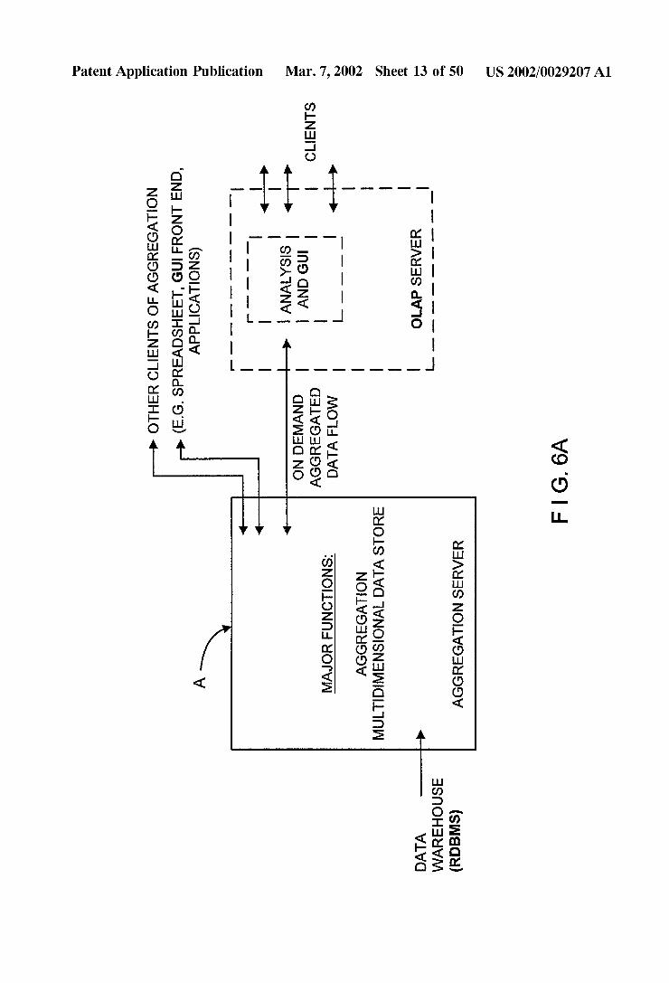
0.133 FIG. 6A is a schematic representation of a gener alized embodiment of a multidimensional on-line analytical processing (MOLAP) system of the present invention com prising a Data Warehouse realized as a relational database, a Stand-alone Aggregration Server of the present invention having an integrated aggregation engine and MDDB, and an OLAP server supporting a plurality of OLAP clients, wherein the Stand-alone Aggregation Server performs aggre gation functions (e.g. Summation of numbers, as well as other mathematical operations, Such as multiplication, Sub traction, division etc.) and multi-dimensional data storage functions,
0.134 FIG. 6B is a schematic block diagram of the Stand-alone Aggregation Server of the illustrative embodi ment shown in FIG. 6A, showing its primary components, namely, a base data interface (e.g. OLDB, OLE-DB, ODBC, SQL, JDBC, API, etc.) for receiving RDBMS flat files lists and other files from the Data Warehouse (RDBMS), a base data loader for receiving base data from the base data interface, configuration manager for managing the operation of the base data interface and base data loader, an aggrega tion engine and MDDB handler for receiving base data from the base loader, performing aggregation operations on the base data, and Storing the base data and aggregated data in the MDDB; an aggregation client interface (e.g. OLDB, OLE-DB, ODBC, SQL, JDBC, API, etc.) and input analyzer for receiving requests from OLAP client machines, cooper ating with the aggregation engine and MDDB handler to generate aggregated data and/or retrieve aggregated data from the MDDB that pertains to the received requests, and returning this aggregated back to the requesting OLAP clients, and a configuration manager for managing the operation of the input analyzer and the aggregation client interface.
0.135 FIG. 6C is a schematic representation of the soft Ware modules comprising the aggregation engine and MDDB handler of the stand-alone Aggregation Server of the illustrative embodiment of the present invention, showing a base data list Structure being Supplied to a hierarchy analysis and reorder module, the output thereof being transferred to

US 2002/0029207 A1
an aggregation management module, the output thereof being transferred to a Storage module Via a storage manage ment module, and a Query Directed Roll-up (QDR) aggre gation management module being provided for receiving database (DB) requests from OLAP client machines (via the aggregation client interface) and managing the operation of the aggregation and Storage management modules of the present invention; 0136 FIG. 6D is a flow chart representation of the primary operations carried out by the (DB) request Serving mechanism within the QDR aggregation management mod ule shown in FIG. 6C; 0.137 FIG. 7A is a schematic representation of a sepa rate-platform type implementation of the Stand-alone Aggre gation Server of the illustrative embodiment of FIG. 6B and a conventional OLAP Server Supporting a plurality of client machines, wherein base data from a Data Warehouse is shown being received by the aggregation Server, realized on a first hardware/software platform (i.e. Platform A) and the Stand-alone Aggregation Server is shown Serving the con ventional OLAP server, realized on a second hardware/ software platform (i.e. Platform B), as well as serving data aggregation requirements of other clients Supporting diverse applications Such as spreadsheet, GUI front end, and appli cations, 0138 FIG. 7B is a schematic representation of a shared platform type implementation of the Stand-alone Aggrega tion Server of the illustrative embodiment of FIG. 6B and a conventional OLAP Server Supporting a plurality of client machines, wherein base data from a Data Warehouse is shown being received by the Stand-alone Aggregation Server, realized on a common hardware/software platform and the aggregation Server is shown Serving the conven tional OLAP server, realized on the same common hard ware/Software platform, as well as Serving data aggregation requirements of other clients Supporting diverse applications Such as spreadsheet, GUI front end, and applications, 0139 FIG. 8A is a data table setting forth information representative of performance benchmarks obtained by the shared-platform type implementation of the Stand-alone Aggregation Server of the illustrative embodiment Serving the conventional OLAP server (i.e. Oracle EXPRESS Server) shown in FIG. 7B, wherein the common hardware/ Software platform is realized using a Pentium II 450 Mhz, 1 GB RAM, 18 GB Disk, running the Microsoft NT operating system (OS); 0140 FIG. 9A is a schematic representation of the first Stage in the method of Segmented aggregation according to the principles of the present invention, showing initial aggregration along the 1st dimension; 0141 FIG. 9B is a schematic representation of the next Stage in the method of Segmented aggregation according to the principles of the present invention, showing that any Segment along dimension 1, Such as the shown Slice, can be Separately aggregated along the remaining dimensions, 2 and 3, and that in general, for an N dimensional System, the Second Stage involves aggregation in N-1 dimensions. The principle of Segementation can be applied on the first Stage as well, however, only a large enough data will justify Such a Sliced procedure in the first dimension. Actually, it is possible to consider each Segment as an N-1 cube, enabling recursive computation.
Mar. 7, 2002
0.142 FIG. 9C1 is a schematic representation of the Query Directed Roll-up (QDR) aggregation method/proce dure of the present invention, showing data aggregation Starting from existing basic data or previously aggregated data in the first dimension (D1), and Such aggregated data being utilized as a basis for QDR aggregation along the Second dimension (D2), 0.143 FIG. 9C2 is a schematic representation of the Query Directed Roll-up (QDR) aggregation method/proce dure of the present invention, showing initial data aggrega tion Starting from existing previously aggregated data in the Second third (D3), and continuing along the third dimension (D3), and thereafter continuing aggregation along the Sec ond dimension (D2); 014.4 FIG. 10A is a schematic representation of the "slice-storage' method of Storing sparse data in the disk storage devices of the MDDB of FIG. 6B in accordance with the principles of the present invention, based on an ascending-ordered indeX along aggregation direction, enabling fast retrieval of data; 014.5 FIG. 10B is a schematic representation of the data organization of data files and the directory file used in the storages of the MDDB of FIG. 6B, and the method of Searching for a queried data point therein using a simple binary Search technique due to the data files ascending order; 0146 FIG. 11A is a schematic representation of three exemplary multi-hierarchical data Structures for Storage of data within the MDDB of FIG. 6B, having three levels of hierarchy, wherein the first level representative of base data is composed of items A,B,F, and G, the Second level is composed of items C.E.H and I, and the third level is composed of a single item D, which is common to all three hierarchical Structures, 0147 FIG. 11 B is a schematic representation of an optimized multi-hierarchical data structure merged from all three hierarchies of FIG. 11A, in accordance with the principles of the present invention; 0148 FIG. 11C(i) through 11C(iv) represent a flow chart description (and accompanying data structures) of the opera tions of an exemplary hierarchy transformation mechanism of the present invention that optimally merges multiple hierarchies into a single hierarchy that is functionally equivalent to the multiple hierarchies. 014.9 FIG. 12 is a schematic representation showing the levels of operations performed by the Stand-alone Aggrega tion Server of FIG. 6B, Summarizing the different enabling components for carrying out the method of Segmented aggregation in accordance with the principles of the present invention; 0150 FIG. 13 is a schematic representation of the stand alone Aggregation Server of the present invention shown as a component of a central data warehouse, Serving the data aggregation needs of URL directory Systems, Data Marts, RDBMSs, ROLAP systems and OLAP systems alike; 0151 FIG. 14 is a schematic representation of a prior art information database System, wherein the present invention may be embodied; 0152 FIG. 15 is a schematic representation of the prior art data warehouse and OLAP System, wherein the present invention may be embodied;

US 2002/0029207 A1
0153 FIGS. 16A-16C are schematic representations of exemplary tables employed in a prior art Relational Data base Management System (RDBMS); FIGS. 16B and 16C illustrate operators (queries) on the table of FIG. 16A, and the result of Such queries, respectively; 0154 FIG. 17A is a schematic representation of an exemplary dimensional Schema (Star Schema) of a relational database; 0155 FIG. 17B is a schematic representation of tables used to implement the schema shown in FIG. 17A, 0156 FIG. 18A is a schematic representation of an exemplary multidimensional Schema (Star Schema); 0157 FIG. 18B is a schematic representation of tables used to implement the schema of FIG. 18A, including Summary tables Storing results of aggregation operations performed on the facts of the central fact table along the time-period dimension, in accordance with conventional teachings, 0158 FIG. 19A is a schematic representation of an exemplary embodiment of a DBMS (for example, an RDBMS as shown) of the present invention comprising a relational datastore and an integrated multidimensional (MDD) aggregation module Supporting queries from a plu rality of clients, wherein the aggregation engine performs aggregation functions (e.g. Summation of numbers, as well as other mathematical operations, Such as multiplication, Subtraction, division etc.) and non-relational multi-dimen Sional data storage functions. 0159 FIG. 19B is a schematic block diagram of the MDD aggregation module of the illustrative embodiment of the present invention shown in FIG. 6A. 0160 FIG. 19C(i) and 19C(ii), taken together, set forth a flow chart representation of the primary operations carried out within the DBMS of the present invention when per forming data aggregation and related Support operations, including the Servicing of user-Submitted (e.g. natural lan guage) queries made on Such aggregated database of the present invention. 0161 FIG. 19D is a flow chart representation of the primary operations carried out by the (DB) request Serving mechanism within the MDD control module shown in FIG. 6B.
0162 FIG. 19E is a schematic representation of the view mechanism of an DBMS that enables users to query on the aggregated data generated and/or Stored in the MDD Aggre gation module according to the present invention. 0163 FIG. 19F is a schematic representation of the trigger mechanism of the DBMS that enables users to query on the aggregated data generated and/or Stored in the MDD Aggregation module according to the present invention. 0164 FIG. 19G is a schematic representation of the DBMS of the present invention, illustrating a logically partitioning into a relational part and a non-relational part. The relational part includes the relational data store (e.g., table(s) and dictionary) and Support mechanisms (e.g., query handling Services). The non-relational part includes the MDD Aggregation Module. Data flows bidirectionally between the relational part and the non-relational part as shown.
Mar. 7, 2002
0.165 FIG. 20A shows a separate-platform type imple mentation of the DBMS system of the illustrative embodi ment shown in FIG. 19A, wherein the relational datastore and Support mechanisms (e.g., query handling, fact table(s) and dictionary of the DBMS) reside on a separate hardware platform and/or OS system from that used to run the MDD Aggregation Module of the present invention. 0166 FIG. 20B shows a common-platform type imple mentation of the DBMS system of the illustrative embodi ment shown in FIG. 19A, wherein the relational datastore and Support mechanisms (e.g., query handling, fact table(s) and dictionary of the DBMS) share the same hardware platform and operating System (OS) that is used to run the MDD Aggregation Module of the present invention. 0167 FIG.21 is a schematic representation of the DBMS of the present invention shown as a component of a central data Warehouse, Serving the data Storage and aggregation needs of a ROLAP system (or other OLAP system). 0168 FIG.22 is a schematic representation of the DBMS of the present invention shown as a component of a central data warehouse, wherein the DBMS includes integrated OLAP Analysis Logic (and preferably an integrated Presen tation Module) that operates cooperatively with the query handling of the DBMS system and the MDD Aggregation Module to enable users of the D B M S system to execute multidimensional reports (e.g., ratios, ranks, transforms, dynamic consolidation, complex filtering, forecasts, query governing, Scheduling, flow control, pre-aggregate inferenc ing, denomalization Support, and/or table partitioning and joins) and preferably perform traditional OLAP analyses (grids, graphs, maps, alerts, drill-down, data pivot, data Surf, Slice and dice, print).
DETAILED DESCRIPTION OF THE PREFERRED EMBODIMENTS OF THE
PRESENT INVENTION
0169. Referring now to FIGS. 6A through 13, the pre ferred embodiments of the method and system of the present invention will be now described in great detail hereinbelow, wherein like elements in the Drawings shall be indicated by like reference numerals.
0170 Through this invention disclosure, the term “aggre gation' and “preaggregation' shall be understood to mean the process of Summation of numbers, as well as other mathematical operations, Such as multiplication, Subtrac tion, division etc. 0171 In general, the Stand-alone aggregation server and methods of and apparatus for data aggregation of the present invention can be employed in a wide range of applications, including MOLAP systems, ROLAP systems, Internet URL directory Systems, personalized on-line e-commerce shop ping Systems, Internet-based Systems requiring real-time control of packet routing and/or Switching, and the like. 0172 For purposes of illustration, initial focus will be accorded to improvements in MOLAP systems, in which knowledge workers are enabled to intuitively, quickly, and flexibly manipulate operational data within a MDDB using familiar business terms in order to provide analytical insight into a busineSS domain of interest.
0173 FIG. 6A illustrates a generalized embodiment of a multidimensional on-line analytical processing (MOLAP)

US 2002/0029207 A1
System of the present invention comprising: a Data Ware house realized as a relational database; a Stand-alone car tridge-Style Aggregation Server of the present invention having an integrated aggregation engine and a MDDB, and an OLAP Server communicating with the Aggregation Server, and supporting a plurality of OLAP clients. In accordance with the principles of the present invention, the Stand-alone Aggregation Server performs aggregation func tions (e.g. Summation of numbers, as well as other math ematical operations, Such as multiplication, Subtraction, division etc.) and multi-dimensional data storage functions. 0.174 Departing from conventional practices, the prin ciples of the present invention teaches moving the aggrega tion engine and the MDDB into a separate Aggregation Server having Standardized interfaces So that it can be plugged-into the OLAP server of virtually any user or vendor. This dramatic move discontinues the restricting dependency of aggregation from the analytical functions of OLAP, and by applying novel and independent algorithms. The Standalone data aggregation Server enables efficient organization and handling of data, fast aggregation proceSS ing, and fast access to and retrieval of any data element in the MDDB.
0.175. As will be described in greater detail hereinafter, the Aggregation Server of the present invention can Serve the data aggregation requirements of other types of Systems besides OLAP systems such as, for example, URL directory management Data Marts, RDBMS, or ROLAP systems. 0176) The Aggregation Server of the present invention excels in performing two distinct functions, namely: the aggregation of data in the MDDB; and the handling of the resulting data base in the MDDB, for “on demand” client use. In the case of Serving an OLAP Server, the Aggregation Server of the present invention focuses on performing these two functions in a high performance manner (i.e. aggregat ing and Storing base data, originated at the Data Warehouse, in a multidimensional storage (MDDB), and providing the results of this data aggregation process “on demand” to the clients, Such as the OLAP Server, Spreadsheet applications, the end user applications. AS Such, the Aggregation Server of the present invention frees each conventional OLAP server, with which it interfaces, from the need of making data aggregations, and therefore allows the conventional OLAP server to concentrate on the primary functions of OLAP Servers, namely: data analysis and Supporting a graphical interface with the user client.
0177 FIG. 6B shows the primary components of the Stand-alone Aggregation Server of the illustrative embodi ment, namely: a base data interface (e.g. OLDB, OLE-DB, ODBC, SQL, JDBC, API, etc.) for receiving RDBMS flat files lists and other files from the Data Warehouse (RDBMS), a base data loader for receiving base data from the base data interface, configuration manager for managing the operation of the base data interface and base data loader, an aggregation engine for receiving base data from the base loader, a multi-dimensional database (MDDB); a MDDB handler, an input analyzer, an aggregation client interface (e.g. OLDB, OLE-DB, ODBC, SQL, API, JDBC, etc.) and a configuration manager for managing the operation of the input analyzer and the aggregation client interface. 0178. During operation, the base data originates at data warehouse or other Sources, Such as external ASCII files,
Mar. 7, 2002
MOLAP server, or others. The Configuration Manager, in order to enable proper communication with all possible Sources and data Structures, configures two blocks, the Base Data Interface and Data Loader. Their configuration is matched with different standards Such as OLDB, OLE-DB, ODBC, SOL, API, JDBC, etc. 0179. As shown in FIG. 6B, the core of the data Aggre gation Server of the present invention comprises: a data Aggregation Engine; a Multidimensional Data Handler (MDDB Handler); and a Multidimensional Data Storage (MDDB). The results of data aggregation are efficiently stored in the MDDB by the MDDB Handler. 0180. As shown in FIGS. 6A and 6B, the stand-alone Aggregation Server of the present invention Serves the OLAP Server (or other requesting computing System) via an aggregation client interface, which preferably conforms to standard interface protocols such as OLDB, OLE-DB, ODBC, SQL, JDBC, an API, etc. Aggregation results required by the OLAP server are supplied on demand. Typically, the OLAP Server disintegrates the query, via parsing process, into Series of requests. Each Such request, Specifying a n-dimensional coordinate, is presented to the Aggregation Server. The Configuration Manager Sets the Aggregation Client Interface and Input Analyzer for a proper communication protocol according to the client user. The Input Analyzer converts the input format to make it Suitable for the MDDB Handler.
0181 An object of the present invention is to make the transfer of data completely transparent to the OLAP user, in a manner which is equivalent to the Storing of data in the MOLAP server's cache and without any query delays. This requires that the Stand-alone Aggregation Server have exceptionally fast response characteristics. This object is enabled by providing the unique data Structure and aggre gation mechanism of the present invention. 0182 FIG. 6C shows the Software modules comprising the aggregation engine and MDDB handler components of the Stand-alone Aggregation Server of the illustrative embodiment. The base data list, as it arrives from RDBMS or text files, has to be analyzed and reordered to optimize hierarchy handling, according to the unique method of the present invention, as described later with reference to FIGS. 11A and 11B.
0183 The function of the aggregation management mod ule is to administrate the aggregation proceSS according to the method illustrated in FIGS. 9A and 9B.
0184. In accordance with the principles of the present invention, data aggregation within the Stand-alone Aggre gation Server can be carried out either as a complete pre-aggregation proceSS, where the base data is fully aggre gated before commencing querying, or as a query directed rollup (QDR) process, where querying is allowed at any Stage of aggregation using the “on-the-fly” data aggregation process of the present invention. The QDR process will be described hereinafter in greater detail with reference to FIG. 9C. The response to a request (i.e. a basic component of a client query), by calling the Aggregation management mod ule for “on-the-fly” data aggregation, or for accessing pre aggregated result data via the Storage management module. The query/request Serving mechanism of the present inven tion within the QDR aggregation management module is illustrated in the flow chart of FIG. 6D.

US 2002/0029207 A1
0185. The function of the Storage management module is to handle multidimensional data in the storage(s) module in a very efficient way, according to the novel method of the present invention, which will be described in detail herein after with reference to FIGS. 10A and 10B.
0186 The request serving mechanism shown in FIG. 6D is controlled by the QDR aggregation management module. Requests are queued and Served one by one. If the required data is already pre-calculated, then it is retrieved by the Storage management module and returned to the client. Otherwise, the required data is calculated “on-the-fly” by the aggregation management module, and the result moved out to the client, while Simultaneously Stored by the Storage management module, shown in FIG. 6C.
0187 FIGS. 7A and 7B outline two different implemen tations of the Stand-alone (cartridge-style) Aggregation Server of the present invention. In both implementations, the Aggregation Server Supplies aggregated results to a client.
0188 FIG. 7A shows a separate-platform type imple mentation of the MOLAP system of the illustrative embodi ment shown in FIG. 6A, wherein the Aggregation Server of the present invention resides on a separate hardware plat form and OS system from that used to run the OLAP server. In this type of implementation, it is even possible to run the Aggregation Server and the OLAP Server on different-type operating systems (e.g. NT, Unix, MAC OS). 0189 FIG. 7B shows a common-platform type imple mentation of the MOLAP system of the illustrative embodi ment shown in FIG. 6B, wherein the Aggregation Server of the present invention and OLAP Server share the same hardware platform and operating System (OS).
0190 FIG. 8A shows a table setting forth the benchmark results of an aggregation engine, implemented on a shared/ common hardware platform and OS, in accordance with the principles of the present invention. The common platform and OS is realized using a Pentium II 450 Mhz, 1 GB RAM, 18 GB Disk, running the Microsoft NT operating system. The six (6) data sets shown in the table differ in number of dimensions, number of hierarchies, measure of Sparcity and data size. A comparison with ORACLE Express, a major OLAP Server, is made. It is evident that the aggregation engine of the present invention outperforms currently lead ing aggregation technology by more than an order of mag nitude.
0191 The segmented data aggregation method of the present invention is described in FIGS. 9A through 9C2. These figures outline a simplified Setting of three dimensions only; however, the following analysis applies to any number of dimensions as well.
0.192 The data is being divided into autonomic segments to minimize the amount of Simultaneously handled data. The initial aggregation is practiced on a Single dimension only, while later on the aggregation proceSS involves all other dimensions.
0193 At the first stage of the aggregation method, an aggregation is performed along dimension 1. The first Stage can be performed on more than one dimension. AS Shown in FIG. 9A, the space of the base data is expanded by the aggregation process.
Mar. 7, 2002
0194 In the next stage shown in FIG. 9B, any segment along dimension 1, Such as the shown slice, can be sepa rately aggregated along the remaining dimensions, 2 and 3. In general, for an N dimensional System, the Second Stage involves aggregation in N-1 dimensions. 0.195 The principle of data segmentation can be applied on the first Stage as well. However, only a large enough data Set will justify Such a sliced procedure in the first dimension. Actually, it is possible to consider each Segment as an N-1 cube, enabling recursive computation. 0196. It is imperative to get aggregation results of a Specific slice before the entire aggregation is completed, or alternatively, to have the roll-up done in a particular Sequence. This novel feature of the aggregation method of the present invention is that it allows the querying to begin, even before the regular aggregation proceSS is accom plished, and Still having fast response. Moreover, in rela tional OLAP and other Systems requiring only partial aggre gations, the QDR proceSS dramatically speeds up the query response.
0197) The QDR process is made feasible by the slice oriented roll-up method of the present invention. After aggregating the first dimension(s), the multidimensional Space is composed of independent multidimensional cubes (slices). These cubes can be processed in any arbitrary Sequence.
0198 Consequently the aggregation process of the present invention can be monitored by means of files, shared memory Sockets, or queues to Statically or dynamically Set the roll-up order. 0199. In order to satisfy a single query coming from a client, before the required aggregation result has been pre pared, the QDR process of the present invention involves performing a fast on-the-fly aggregation (roll-up) involving only a thin Slice of the multidimensional data. 0200 FIG. 9C1 shows a slice required for building-up a roll-up result of the 2" dimension. In case 1, as shown, the aggregation Starts from an existing data, either basic or previously aggregated in the first dimension. This data is utilized as a basis for QDR aggregation along the Second dimension. In case 2, due to lack of previous data, a QDR involves an initial Slice aggregation along dimension 3, and thereafter aggregation along the 2" dimension. 0201 FIG.9C2 shows two corresponding QDR cases for gaining results in the 3d dimension. Cases 1 and 2 differ in the amount of initial aggregation required in 2" dimension. 0202 FIG. 10A illustrates the “Slice-Storage” method of Storing sparse data on Storage disks. In general, this data Storage method is based on the principle that an ascending ordered indeX along aggregation direction, enables fast retrieval of data. FIG. 10A illustrates a unit-wide slice of the multidimensional cube of data. Since the data is sparse, only few non-NA data points exist. These points are indexed as follows. The Data File consists of data records, in which each n-1 dimensional Slice is being Stored, in a Separate record. These records have a varying length, according to the amount of non-NA Stored points. For each registered point in the record, IND Stands for an indeX in a n-dimensional cube, and Data Stands for the value of a given point in the cube.

US 2002/0029207 A1
0203 FIG. 10B illustrates a novel method for randomly searching for a queried data point in the MDDB of FIG. 6B by using a novel technique of organizing data files and the directory file used in the storages of the MDDB, so that a Simple binary Search technique can then be employed within the Aggregation Server of the prSent invention. According to this method, a metafile termed DIR File, keeps pointers to Data Files as well as additional parameterS Such as the Start and end addresses of data record (IND, IND), its location within the Data File, record size (n), file's physical address on disk (D Path), and auxiliary information on the record (Flags). 0204. A search for a queried data point is then performed by an access to the DIR file. The search along the file can be made using a simple binary Search due to file's ascending order. When the record is found, it is then loaded into main memory to Search for the required point, characterized by its index IND. The attached Data field represents the queried value. In case the exact indeX is not found, it means that the point is a NA. 0205. In another aspect of the present invention, a novel method is provided for optimally merging multiple hierar chies in multi-hierarchical Structures. The method, illus trated in FIGS. 11A, 11B, and 11C is preferably used by the Aggregation Server of the present invention in processing the table data (base data), as it arrives from RDBMS. 0206. According to the devised method, the inner order of hierarchies within a dimension is optimized, to achieve efficient data handling for Summations and other mathemati cal formulas (termed in general "Aggregation'). The order of hierarchy is defined externally. It is brought from a data Source to the Stand-alone aggregation engine, as a descriptor of data, before the data itself. In the illustrative embodiment, the method assumes hierarchical relations of the data, as shown in FIG. 11A. The way data items are ordered in the memory Space of the Aggregation Server, with regard to the hierarchy, has a significant impact on its data handling efficiency. 0207. Notably, when using prior art techniques, multiple handling of data elements, which occurs when a data ele ment is accessed more than once during aggregation pro ceSS, has been hitherto unavoidable when the main concern is to effectively handle the Sparse data. The data Structures used in prior art data handling methods have been designed for fast access to a non NA data. According to prior art techniques, each acceSS is associated with a timely Search and retrieval in the data Structure. For the massive amount of data typically accessed from a Data Warehouse in an OLAP application, Such multiple handling of data elements has significantly degraded the efficiency of prior art data aggregation processes. When using prior art data handling techniques, the data element D shown in FIG. 11A must be accessed three times, causing poor aggregation perfor
CC.
0208. In accordance with the data handling method of the present invention, the data is being pre-ordered for a Singular handling, as opposed to multiple handling taught by prior art methods. According to the present invention, elements of base data and their aggregated results are contiguously Stored in a way that each element will be accessed only once. This particular order allows a forward-only handling, never backward. Once a base data element is Stored, or aggregated
Mar. 7, 2002
result is generated and Stored, it is never to be retrieved again for further aggregation. As a result the Storage access is minimized. This way of Singular handling greatly elevates the aggregation efficiency of large data bases. An efficient handling method as used in the present invention, is shown in FIG. 7A. The data element D, as any other element, is accessed and handled only once.
0209 FIG. 11A shows an example of a multi-hierarchi cal database Structure having 3 hierarchies. AS shown, the base data has a dimension that includes items A,B,F, and G. The second level is composed of items C.E.H and I. The third level has a single item D, which is common to all three hierarchical Structures. In accordance with the method of the present invention, a minimal computing path is always taken. For example, according to the method of the present invention, item D will be calculated as part of Structure 1, requiring two mathematical operations only, rather than as in Structure 3, which would need four mathematical operations. FIG. 11B depicts an optimized structure merged from all three hierarchies.
0210 FIG. 11C(i) through 11C(iv) represent a flow chart description (and accompanying data structures) of the opera tions of an exemplary hierarchy transformation mechanism of the present invention that optimally merges multiple hierarchies into a single hierarchy that is functionally equivalent to the multiple hierarchies. For the Sake of description, the data Structures correspond to exemplary hierarchical Structures described above with respect to FIGS. 11(A) and 11(B). As illustrated in FIG. 11C(i), in step 1101, a catalogue is loaded from the DBMS system. As is conventional, the catalogue includes data ("hierarchy descriptor data') describing multiple hierarchies for at least one dimension of the data stored in the DBMS. In step 1103, this hierarchy descriptor data is extracted from the cata logue. A loop (steps 1105-1119) is performed over the items in the multiple hierarchy described by the hierarchy descrip tor data.
0211. In the loop 1105-1119, a given item in the multiple hierarchy is selected (step 1107); and, in step 1109, the parent(s) (if any)-including grandparents, great-grandpar ents, etc.—of the given item are identified and added to an entry (for the given item) in a parent list data structure, which is illustrated in FIG. 11C(v). Each entry in the parent list corresponds to a specific item and includes Zero or more identifiers for items that are parents (or grandparents, or great-grandparents) of the specific item. In addition, an inner loop (steps 1111-1117) is performed over the hierarchies of the multiple hierarchies described by the hierarchy descrip tor data, wherein in step 1113 one of the multiple hierarchies is selected. In step 1115, the child of the given item in the selected hierarchy (if any) is identified and added (if need be) to a group of identifiers in an entry (for the given item) in a child list data structure, which is illustrated in FIG. 11C(vi). Each entry in the child list corresponds to a specific item and includes Zero or more groups of identifiers each identifying a child of the Specific item. Each group corre sponds to one or more of the hierarchies described by the hierarchy descriptor data.
0212. The operation then continues to steps 1121 and 1123 as illustrated in FIG. 11C(ii) to verify the integrity of the multiple hierarchies described by the hierarchy descrip tor data (step 1121) and fix (or report to the user) any errors

US 2002/0029207 A1
discovered therein (step 1123). Preferably, the integrity of the multiple hierarchies is verified in step 1121 by iteratively expanding each group of identifiers in the child list to include the children, grandchildren, etc of any item listed in the group. If the child(ren) for each group for a specific item do not match, a verification error is encountered, and Such error is fixed (or reported to the user (step 1123). The operation then proceeds to a loop (steps 1125-1133) over the items in the child list.
0213) In the loop (steps 1125-1133), a given item in the child list is identified in step 1127. In step 1129, the entry in the child list for the given item is examined to determine if the given item has no children (e.g., the corresponding entry is null). If So, the operation continues to step 1131 to add an entry for the item in level 0 of an ordered list data structure, which is illustrated in FIG.11C(vii); otherwise the operation continues to process the next item of the child list in the loop. Each entry in a given level of the order list corresponds to a specific item and includes Zero or more identifiers each identifying a child of the specific item. The levels of the order list described the transformed hierarchy as will readily become apparent in light of the following. Essentially, loop 1125-1333 builds the lowest level (level 0) of the trans formed hierarchy.
0214. After loop 1125-1133, operation continues to pro cess the lowest level to derive the next higher level, and iterate over this process to build out the entire transformed hierarchy. More specifically, in step 1135, a “current level.” variable is set to identify the lowest level. In step 1137, the items of the “current level” of the ordered list are copied to a work list. Instep 1139, it is determined if the worklist is empty. If So, the operation ends; otherwise operation con tinues to step 1141 wherein a loop (steps 1141-1159) is performed over the items in the work list.
0215. In step 1143, a given item in the work list is identified and operation continues to an inner loop (steps 1145-1155) over the parent(s) of the given item (which are Specified in the parent list entry for the given item). In Step 1147 of the inner loop, a given parent of the given item is identified. In step 1149, it is determined whether any other parent (e.g., a parent other than the given patent) of the given item is a child of the given parent (as specified in the child list entry for the given parent). If So, operation continues to step 1155 to process the next parent of the given item in the inner loop; otherwise, operation continues to StepS 1151 and 1153. In step 1151, an entry for the given parent is added to the next level (current level+1) of the ordered list, if it does not exist there already. In step 1153, if no children of the given item (as specified in the entry for the given item in the current level of the ordered list) matches (e.g., is covered by) any child (or grandchild or great grandchild etc) of item(s) in the entry for the given parent in the next level of the ordered list, the given item is added to the entry for the given parent in the next level of the ordered list. Levels 1 and 2 of the ordered list for the example described above are shown in FIGS. 11C(viii) and 11C(ix), respectively. The children (including grandchildren and great grandchildren. etc) of an item in the entry for a given parent in the next level of the ordered list may be identified by the information encoded in the lower levels of the ordered list. After step 1153, opera tion continues to step 1155 to process the next parent of the given item in the inner loop (steps 1145-1155).
Mar. 7, 2002
0216. After processing the inner loop (steps 1145-1155), operation continues to step 1157 to delete the given item from the work list, and processing continues to step 1159 to process the next item of the work list in the loop (steps 1141-1159). 0217. After processing the loop (steps 1141-1159), the ordered list (e.g., transformed hierarchy) has been built for the next higher level. The operation continues to step 1161 to increment the current level to the next higher level, and operation returns (in step 1163) to step 1138 to build the next higher level, until the highest level is reached (determined in step 1139) and the operation ends. 0218 FIG. 12 Summarizes the components of an exem plary aggregation module that takes advantage of the hier archy transformation technique described above. More spe cifically, the aggregation module includes an hierarchy transformation module that optimally merges multiple hier archies into a Single hierarchy that is functionally equivalent to the multiple hierarchies. A Second module loads and indexes the base data supplied from the DBMS using the optimal hierarchy generated by the hierarchy transformation module. An aggregation engine performs aggregation opera tions on the base data. During the aggregation operations along the dimension Specified by the optimal hierarchy, the results of the aggregation operations of the level 0 items may be used in the aggregation operations of the level 1 items, the results of the aggregation operations of the level 1 items may be used in the aggregation operations of the level 2 items, etc. Based on these operations, the loading and indexing operations of the base data, along with the aggregation become very efficient, minimizing memory and Storage access, and Speeding up Storing and retrieval operations. 0219 FIG. 13 shows the stand-alone Aggregation Server of the present invention as a component of a central data warehouse, Serving the data aggregation needs of URL directory systems, Data Marts, RDBMSs, ROLAP systems and OLAP systems alike. 0220. The reason for the central multidimensional data base's rise to corporate necessity is that it facilitates flexible, high-performance acceSS and analysis of large Volumes of complex and interrelated data. 0221) A stand-alone specialized aggregation server, Simultaneously serving many different kinds of clients (e.g. data mart, OLAP, URL, RDBMS), has the power of deliv ering an enterprise-wide aggregation in a cost-effective way. This kind of server eliminates the roll-up redundancy over the group of clients, delivering Scalability and flexibility.
0222 Performance associated with central data ware house is an important consideration in the overall approach. Performance includes aggregation times and query response. 0223) Effective interactive query applications require near real-time performance, measured in Seconds. These application performances translate directly into the aggre gation requirements.
0224. In the prior art, in case of MOLAP, a full pre aggregation must be done before Starting querying. In the present invention, in contrast to prior art, the query directed roll-up (QDR) allows instant querying, while the full pre aggregation is done in the background. In cases a full pre-aggregation is preferred, the currently invented aggre

US 2002/0029207 A1
gation outperforms any prior art. For the ROLAP and RDBMS clients, partial aggregations maximize query per formance. In both cases fast aggregation proceSS is impera tive. The aggregation performance of the current invention is by orders of magnitude higher than that of the prior art.
0225. The stand-alone scalable aggregation server of the present invention can be used in any MOLAP system environment for answering questions about corporate per formance in a particular market, economic trends, consumer behaviors, weather conditions, population trends, or the State of any physical, Social, biological or other System or phe nomenon on which different types or categories of informa tion, organizable in accordance with a predetermined dimen sional hierarchy, are collected and stored within a RDBMS of one Sort or another. Regardless of the particular applica tion Selected, the address data mapping processes of the present invention will provide a quick and efficient way of managing a MDDB and also enabling decision Support capabilities utilizing the Same in diverse application envi rOnmentS.
0226. The stand-alone “cartridge-style” plug-in features of the data aggregation Server of the present invention, provides freedom in designing an optimized multidimen Sional data Structure and handling method for aggregation, provides freedom in designing a generic aggregation Server matching all OLAP vendors, and enables enterprise-wide centralized aggregation. 0227. The method of Segmented Aggregation employed in the aggregation server of the present invention provides flexibility, Scalability, a condition for Query Directed Aggre gation, and Speed improvement.
0228. The method of Multidimensional data organization and indexing employed in the aggregation Server of the present invention provides fast Storage and retrieval, a condition for Segmented Aggregation, improves the Storing, handling, and retrieval of data in a fast manner, and con tributes to Structural flexibility to allow Sliced aggregation and QDR. It also enables the forwarding and Single handling of data with improvements in Speed performance.
0229. The method of Query Directed Aggregation (QDR) employed in the aggregation Server of the present invention minimizes the data handling operations in multi-hierarchy data Structures.
0230. The method of Query Directed Aggregation (QDR) employed in the aggregation Server of the present invention eliminates the need to wait for full aggregation to be completed, and provides build-up aggregated data required for full aggregation.
0231. In another aspect of the present invention, an improved DBMS system (e.g., RDBMS system, object oriented database System or object/relational database SyS tem) is provided that excels in performing two distinct functions, namely: the aggregation of data; and the handling of the resulting data for “on demand” client use. Moreover, because of improved data aggregation capabilities, the DBMS of the present invention can be employed in a wide range of applications, including Data Warehouses Support ing OLAP systems and the like. For purposes of illustration, initial focus will be accorded to the DBMS of the present invention. Referring now to FIG. 19 through FIG. 21, the
Mar. 7, 2002
preferred embodiments of the method and system of the present invention will be now described in great detail herein below.
0232 Through this document, the term “aggregation” and “pre-aggregation' shall be understood to mean the process of Summation of numbers, as well as other math ematical operations, Such as multiplication, Subtraction, division etc. It shall be understood that preaggregation operations occur asynchronously with respect to the tradi tional query processing operations. Moreover, the term "atomic data” shall be understood to refer to the lowest level of data granularity required for effective decision making. In the case of a retail merchandising manager, atomic data may refer to information by store, by day, and by item. For a banker, atomic data may be information by account, by transaction, and by branch. 0233 FIG. 19A illustrates the primary components of an illustrative embodiment of an DBMS of the present inven tion, namely: Support mechanisms including a query inter face and query handler, a relational data Store including one or more tables Storing at least the atomic data (and possibly Summary tables) and a meta-data store for storing a dictio nary (Sometimes referred to as a catalogue or directory); and an MDD Aggregation Module that Stores atomic data and aggregated data in a MDDB. The MDDB is a non-relational data Structure-it uses other data Structures, either instead of or in addition to tables-to store data. For illustrative purposes, FIG. 19A illustrates an RDBMS wherein the relational data Store includes fact tables and a dictionary.
0234. It should be noted that the DBMS typically includes additional components (not shown) that are not relevant to the present invention. The query interface and query handler Service user-Submitted queries (in the pre ferred embodiment, SQL query statements) forwarded, for example, from a client machine over a network as shown. The query handler and relational data store (tables and meta-data store) are operably coupled to the MDD Aggre gation Module. Importantly, the query handler and inte grated MDD Aggregation Module operate to provide for dramatically improved query response times for data aggre gation operations and drill-downs. Moreover, it is an object of the present invention is to make user-querying of the non-relational MDDB no different than querying a relational table of the DBMS, in a manner that minimizes the delays asSociated with queries that involve aggregation or drill down operations. This object is enabled by providing the novel DBMS System and integrated aggregation mechanism of the present invention. 0235 FIG. 19B shows the primary components of an illustrative embodiment of the MDD Aggregation Module of FIG. 19A, namely: a base data loader for loading the directory and table(s) of relational data store of the DBMS; an aggregation engine for receiving dimension data and atomic data from the base loader, a multi-dimensional database (MDDB); a MDDB handler and an SQL handler that operate cooperatively with the query handler of the DBMS to provide users with query access to the MDD Aggregation Module, and a control module for managing the operation of the components of the MDD aggregation module. The base data loader may load the directory and table(s) of the relational data store over a standard interface (such as OLDB, OLE-DB, ODBC, SQL, API, JDBC, etc.).

US 2002/0029207 A1
In this case, the DBMS and base data loader include components that provide communication of Such data over these Standard interfaces. Such interface components are well known in the art. For example, Such interface compo nents are readily available from Attunity Corporation, http:// www.attunity.com.
0236. During operation, base data originates from the table(s) of the DBMS. The core data aggregation operations are performed by the Aggregation Engine; a Multidimen sional Data (MDDB) Handler; and a Multidimensional Data Storage (MDDB). The results of data aggregation are effi ciently stored in the MDDB by the MDDB Handler. The SQL handler of the MDD Aggregation module services user-submitted queries (in the preferred embodiment, SQL query Statements) forwarded from the query handler of the DBMS. The SQL handler of the MDD Aggregation module may communicate with the query handler of the DBMS over a standard interface (such as OLDB, OLE-DB, ODBC, SQL, API, JDBC, etc.). In this case, the support mechanisms of the RDBMS and SQL handler include components that provide communication of Such data over these Standard interfaces. Such interface components are well known in the art. Aggregation (or drill down results) are retrieved on demand and returned to the user.
0237) Typically, a user interacts with a client machine (for example, using a web-enabled browser) to generate a natural language query, that is communicated to the query interface of the DBMS, for example over a network as shown. The query interface disintegrates the query, via parsing, into a Series of requests (in the preferred embodi ment, SQL statements) that are communicated to the query handler of the DBMS. It should be noted that the functions of the query interface may be implemented in a module that is not part of the DBMS (for example, in the client machine). The query handler of the DBMS forwards requests that involve data stored in the MDD of the MDD Aggregation module to the SQL hander of the MDD Aggregation module for Servicing. Each request Specifies a set of n-dimensions. The SQL handler of the MDD Aggregation Module extracts this set of dimensions and operates cooperatively with the MDD handler to address the MDDB using the set of dimensions, retrieve the addressed data from the MDDB, and return the results to the user via the query handler of the DBMS.
0238 FIG. 19C(i) and 19C(ii) is a flow chart illustrating the operations of an illustrative DBMS of the present invention. In step 601, the base data loader of the MDD Aggregation Module loads the dictionary (or catalog) from the meta-data store of the DBMS. In performing this func tion, the base data loader may utilize an adapter (interface) that maps the data types of the dictionary of the DBMS (or that maps a Standard data type used to represent the dictio nary of the DBMS) into the data types used in the MDD aggregation module. In addition, the base data loader extracts the dimensions from the dictionary and forwards the dimensions to the aggregation engine of the MDD Aggre gation Module.
0239). In step 603, the base data loader loads table(s) from the DBMS. In performing this function, the base data loader may utilize an adapter (interface) that maps the data types of the table(s) of the DBMS (or that maps a standard data type used to represent the fact table(s) of the DBMS) into the data
Mar. 7, 2002
types used in the MDD Aggregation Module. In addition, the base data loader extracts the atomic data from the table(s), and forwards the atomic data to the aggregation engine. 0240. In step 605, the aggregation engine performs aggregation operations (i.e., roll-up operation) on the atomic data (provided by the base data loader in step 603) along at least one of the dimensions (extracted from the dictionary of the DBMS in step 601) and operates cooperatively with the MDD handler to Store the resultant aggregated data in the MDDB. A more detailed description of exemplary aggrega tion operations according to a preferred embodiment of the present invention is set forth below with respect to the QDR process of FIGS. 9A-9C. 0241. In step 607, a reference is defined that provides users with the ability to query the data generated by the MDD Aggregation Module and/or stored in the MDDB of the MDD Aggregation Module. This reference is preferably defined using the Create View SQL statement, which allows the user to: i) define a table name (TN) associated with the MDDB stored in the MDD Aggregation Module, and ii) define a link used to route SQL statements on the table TN to the MDD Aggregation Module. In this embodiment, the view mechanism of the DBMS enables reference and linking to the data stored in the MDDB of the MDD Aggregation Engine as illustrated in FIG. 6(E). A more detailed descrip tion of the view mechanism and the Create View SQL statement may be found in C. J. Date, “An Introduction to Database Systems.” Addison-Wesley, Seventh Edition, 2000, pp. 289-326, herein incorporated by reference in its entirety. Thus, the view mechanism enables the query han dler of the DBMS system to forward any SQL query on table TN to the MDD aggregation module via the associated link. In an alternative embodiment, a direct mechanism (e.g., NA trigger mechanism) may be used to enable the DBMS System to reference and link to the data generated by the MDD Aggregation Module and/or stored in the MDDB of the MDD Aggregation Engine as illustrated in FIG. 6F. A more detailed description of trigger mechanisms and meth ods may be found in C. J. Date, “An Introduction to Database Systems.” Addison-Wesley, Seventh Edition, 2000, pp. 250, 266, herein incorporated by reference in its entirety.
0242. In step 609, a user interacts with a client machine to generate a query, and the query is communicated to the query interface. The query interface generate one or more SQL statements. These SQL statements may refer to data Stored in tables of the relational datastore, or may refer to the reference defined in step 607 (this reference refers to the data stored in the MDDB of the MDD Aggregation Module). These SQL statement(s) are forwarded to the query handler of the DBMS.
0243 In step 611, the query handler receives the SQL Statement(s); and optionally transforms Such SQL state ment(s) to optimize the SQL statement(s) for more efficient query handling. Such transformations are well known in the art. For example, See Kimball, Aggregation Navigation With (Almost) No MetaData”, DBMS Data Warehouse Supple ment, August 1996, available at http://www.dbmsmag.com/ 9608d54.html.
0244. In step 613: the query handler determines whether the received SQL statement(s) or transformed SQL state ment(s) is on the reference generated in step 607. If so,

US 2002/0029207 A1
operation continues to Step 615; otherwise normal query handling operations continue in Step 625 wherein the rela tional datastore is accessed to extract, Store, and/or manipu late the data Stored therein as directed by the query, and results are returned back to the user via the client machine, if needed.
0245. In step 615, the received SQL statement(s) or transformed SQL statement(s) is routed to the MDD aggre gation engine for processing in Step 617 using the link for the reference as described above with respect to step 607. 0246. In step 617, the SQL statement(s) is received by the SQL handler of the MDD Aggregation Module, wherein a Set of one or more N-dimensional coordinates are extracted from the SQL statement. In performing this function, SQL handler may utilize an adapter (interface) that maps the data types of the SQL statement issued by query handler of the DBMS (or that maps a standard data type used to represent the SQL statement issued by query handler of the DBMS) into the data types used in the MDD aggregation module. 0247. In step 619, the set of N-dimensional coordinates extracted in step 617 are used by the MDD handler to address the MDDB and retrieve the corresponding data from the MDDB.
0248 Finally, in step 621, the retrieved data is returned to the user via the DBMS (for example, by forwarding the retrieved data to the SQL handler, which returns the retrieved data to the query handler of the DBMS system, which returns the results of the user-submitted query to the user via the client machine), and the operation ends. 0249. It should be noted that the table data (base data), as
it arrives from DBMS, may be analyzed and reordered to optimize hierarchy handling, according to the unique method of the present invention, as described above with reference to FIGS. 11A, 11B, and 11C.
0250 Moreover, the MDD control module of the MDD Aggregation Module preferably administers the aggregation process according to the method illustrated in FIGS. 9A and 9B. Thus, in accordance with the principles of the present invention, data aggregation within the DBMS can be carried out either as a complete pre-aggregation process, where the base data is fully aggregated before commencing querying, or as a query directed roll-up (QDR) process, where query ing is allowed at any Stage of aggregation using the “on the-fly” data aggregation process of the present invention. The QDR process will be described hereinafter in greater detail with reference to FIG. 9C. The response to a request (i.e. a basic component of a client query) requiring “on-the fly data aggregation, or requiring access to pre-aggregated result data via the MDD handler is provided by a query/ request Serving mechanism of the present invention within the MDD control module, the primary operations of which are illustrated in the flow chart of FIG. 6D. The function of the MDD Handler is to handle multidimensional data in the Storage(s) module in a very efficient way, according to the novel method of the present invention, which will be described in detail hereinafter with reference to FIGS. 10A and 10B.
0251) The SQL handling mechanism shown in FIG. 6D is controlled by the MDD control module. Requests are queued and Served one by one. If the required data is already pre-calculated, then it is retrieved by the MDD handler and
Mar. 7, 2002
returned to the client. Otherwise, the required data is cal culated “on-the-fly” by the aggregation engine, and the result moved out to the client, while simultaneously Stored by the MDD handler, shown in FIG. 6C. 0252) As illustrated in FIG. 19G, the DBMS of the present invention as described above may be logically partitioned into a relational part and a non-relational part. The relational part includes the relational datastore (e.g., table(s) and dictionary) and Support mechanisms (e.g., query handling Services). The non-relational part includes the MDD Aggregation Module. As described above, bi-direc tional data flow occurs between the relational part and the non-relational part as shown. More specifically, during data load operations, data is loaded from the relational part (i.e., the relational datastore) into the non-relational part, wherein it is aggregated and Stored in the MDDB. And during query Servicing operations, when a given query references data Stored in the MDDB, data pertaining to the query is gener ated by the non-relational part (e.g., generated and/or retrieved from the MDDB) and supplied to the relational part (e.g., query Servicing mechanism) for communication back to the user. Such bi-directional data flow represents an important distinguishing feature with respect to the prior art. For example, in the prior art MOLAP architecture as illus trated in FIG. 1B, unidirectional data flows occurs from the relational data base (e.g., the Data Warehouse RDBMS system) into the MDDB during data loading operations. 0253 FIGS. 20A and 20B outline two different imple mentations of the DBMS of the present invention. In both implementations, the query handler of the DBMS system Supplies aggregated results retrieved from the MDD to a client.
0254 FIG. 20A shows a separate-platform implementa tion of the DBMS system of the illustrative embodiment shown in FIG. 19A, wherein the relational part of the DBMS reside on a separate hardware platform and/or OS system from that used to run the non-relational part (MDD Aggregation Module). In this type of implementation, it is even possible to run parts of the DBMS system and the MDD Aggregation Module on different-type operating Sys tems (e.g. NT, Unix, MAC OS). 0255 FIG. 20B shows a common-platform implementa tion of the DBMS system of the illustrative embodiment shown in FIG. 20A, wherein the relational part of the DBMS share the same hardware platform and operating system (OS) that is used to run the non-relational part (MDD Aggregation Module). 0256 FIG. 21 shows the improved DBMS (e.g., RDBMS) of the present invention as a component of a data Warehouse, Serving the data Storage and aggregation needs of a ROLAP system (or other OLAP systems alike). Impor tantly, the improved DBMS of the present invention pro vides flexible, high-performance acceSS and analysis of large Volumes of complex and interrelated data. Moreover, the improved Data Warehouse DBMS of the present invention can Simultaneously serve many different kinds of clients (e.g. data mart, OLAP, URL) and has the power of delivering an enterprise-Wide data Storage and aggregation in a cost effective way. 0257 This kind of system eliminates redundancy over the group of clients, delivering Scalability and flexibility. More
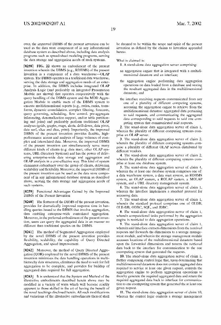
US 2002/0029207 A1
over, the improved DBMS of the present invention can be used as the data Store component of in any informational database System as described above, including data analysis programs Such as Spread-sheet modeling programs, Serving the data Storage and aggregation needs of Such Systems.
0258 FIG. 22 shows an embodiment of the present invention wherein the DBMS (e.g., RDBMS) of the present invention is a component of a data warehouse-OLAP system. The DBMS operates as a traditional data warehouse, Serving the data Storage and aggregation needs of an enter prise. In addition, the DBMS includes integrated OLAP Analysis Logic (and preferably an integrated Presentation Module not shown) that operates cooperatively with the query handling of the DBMS system and the MDD Aggre gation Module to enable users of the DBMS system to execute multidimensional reports (e.g., ratios, ranks, trans forms, dynamic consolidation, complex filtering, forecasts, query governing, Scheduling, flow control, pre-aggregate inferencing, denomalization Support, and/or table partition ing and joins) and preferably perform traditional OLAP analyses (grids, graphs, maps, alerts, drill-down, data pivot, data Surf, slice and dice, print). Importantly, the improved DBMS of the present invention provides flexible, high performance access and analysis of large Volumes of com plex and interrelated data. Moreover, the improved DBMS of the present invention can simultaneously Serve many different kinds of clients (e.g. data mart, other OLAP sys tems, URL-Directory Systems) and has the power of deliv ering enterprise-wide data Storage and aggregation and OLAP analysis in a cost-effective way. This kind of system eliminates redundancy over the group of clients, delivering scalability and flexibility. Moreover, the improved DBMS of the present invention can be used as the data Store compo nent of in any informational database System as described above, Serving the data Storage and aggregation needs of Such systems. 0259 Functional Advantages Gained by the Improved DBMS of the Present Invention
0260 The features of the DBMS of the present invention, provides for dramatically improved response time in han dling queries issued to the DBMS that involve aggregation, thus enabling enterprise-wide centralized aggregation. Moreover, in the preferred embodiment of the present inven tion, users can query the aggregated data in an manner no different than traditional queries on the DBMS. 0261) The method of Segmented Aggregation employed by the novel DBMS of the present invention provides flexibility, Scalability, the capability of Query Directed Aggregation, and Speed improvement.
0262 Moreover, the method of Query Directed Aggre gation (QDR) employed by the novel DBMS of the present invention minimizes the data handling operations in multi hierarchy data Structures, eliminates the need to wait for full aggregation to be complete, and provides for buildup of aggregated data required for full aggregation.
0263. It is understood that the System and Method of the illustrative embodiments described herein above may be modified in a variety of ways which will become readily apparent to those skilled in the art of having the benefit of the novel teachings disclosed herein. All Such modifications and variations of the illustrative embodiments thereof shall
Mar. 7, 2002
be deemed to be within the Scope and Spirit of the present invention as defined by the claims to Invention appended hereto.
What is claimed is: 1. A Stand-alone data aggregation Server comprising: an aggregation engine that is integrated with a multidi
mensional datastore and an interface; the aggregation engine performing data aggregation
operations on data loaded from a database and Storing the resultant aggregated data in the multidimensional datastore; and
the interface receiving requests communicated from any one of a plurality of different computing Systems, accessing the aggregation engine to retrieve from the multidimensional datastore aggregated data pertaining to Said requests, and communicating the aggregated data corresponding to Said requests to Said one com puting System that communicated Said requests.
2. The Stand-alone data aggregation Server of claim 1, wherein the plurality of different computing Systems com prise an OLAP server.
3. The Stand-alone data aggregation Server of claim 2, wherein the plurality of different computing Systems com prise a plurality of different OLAP servers distributed by different vendors.
4. The Stand-alone data aggregation Server of claim 2, wherein the plurality of different computing Systems com prise at least one database System.
5. The Stand-alone data aggregation Server of claim 4, wherein the at least one database System comprises one of: a data warehouse system, a data mart system, an RDBMS system, an OLAP system, a ROLAP system, a MOLAP System, and a URL directory management System.
6. The Stand-alone data aggregation Server of claim 1, wherein the interface implements a Standard protocol for accessing data.
7. The Stand-alone data aggregation Server of claim 1, wherein the standard protocol comprises one of OLDB, OLE-DB, ODBC, SQL, and JDBC.
8. The Stand-alone data aggregration Server of claim 1, wherein computational tasks performed by the aggregation engine is restricted to data aggregation operations.
9. The Stand-alone data aggregation Server of claim 1, wherein Said interface extracts dimensions from the received requests and forwards the dimensions to a storage manage ment module, and wherein the Storage management module accesses locations of the multidimensional datastore based upon the forwarded dimensions and returns the retrieved data back to the interface for communication to the one coomputing System that generated the requests.
10. The Stand-alone data aggregation Server of claim 1, further comprising control logic that, upon determining that multidimensional datastore does not contain aggregated data required to Service at least one given request, controls the aggregation engine to perform aggregation operations to thereby generate the required aggregated data and return the required aggregated data back to interface for communica tion to one coomputing System that generated the at least one given request.
11. The Stand-alone data aggregation Server of claim 10, wherein the control logic controls a storage management

US 2002/0029207 A1
module to Store the required aggregation data generated by the aggregation engine in the multidimensional database.
12. The Stand-alone data aggregation Server of claim 1, wherein data Stored in the multidimensional datastore is logically partitioned into N dimensions, wherein the aggre gation engine performs a first stage of aggregation opera tions along a first dimension, and performs and Second Stage of aggregation operations for a given slice in the first dimension along N-1 dimensions other than the first dimen SO.
13. The Stand-alone data aggregation Server of claim 12, wherein the aggregation engine Stores the resultant data of aggregration operations for the given Slice as a record in a data file, wherein location of the record in the data file is Stored in a directory.
14. The Stand-alone data aggregation Server of claim 13, wherein the directory Stores, for a given record, a start address and end address of the record and a physical address of the data file.
15. The Stand-alone data aggregation Server of claim 1, wherein time delay in responding to Said requests is equiva lent to accessing a local datastore of the one computer System.
16. A relational database management system (RDBMS) comprising:
a relational datastore Storing fact data; an aggregation module, operatively coupled to the rela
tional datastore, for aggregating the fact data and Storing the resultant aggregated data in a non-relational multi-dimensional datastore;
a reference generating mechanism for generating a first reference to aggregated fact data generated by the aggregation module; and
a query processing mechanism for processing a given query Statement, wherein, upon identifying that the given query Statement is on Said first reference, com municates with Said aggregation module to retrieve portions of aggregated fact data pointed to by Said first reference that are relevant to Said given query State ment.
17. The RDBMS of claim 16, wherein said reference generating mechanism generates a Second reference to fact data Stored in the relational datastore.
18. The RDBMS of claim 16, wherein said aggregation module includes a query handling mechanism for receiving query Statements, and wherein communication between said query processing mechanism and Said query handling mechanism is accomplished by forwarding the given query Statement to the query handling mechanism of the aggrega tion module.
19. The RDBMS of claim 18, wherein said query handling mechanism extracts dimensions from the received query Statement and forwards the dimensions to a storage handler, wherein the Storage handler accesses locations of the non relational multi-dimensional datastore based upon the for warded dimensions and returns the retrieved data for com munication to the user.
20. The RDBMS of claim 16, wherein said aggregation module includes a data loading mechanism for loading at least fact data from the relational datastore, an aggregation engine for aggregating the fact data, and a storage handler for Storing the fact data and resultant aggregated fact data in the non-relational multi-dimensional datastore.
20 Mar. 7, 2002
21. The RDBMS of claim 20, wherein said aggregation module includes control logic that, upon determining that the non-relational multi-dimensional datastore does not con tain data required to Service the given query Statement, controls the aggregation engine to aggregate at least fact data required to Service the given query Statement and controls the aggregation module to return the aggregated data for communication to the user.
22. The RDBMS of claim 16, further comprising OLAP analysis logic integral to the RDBMS.
23. The RDBMS of claim 16, for use as an enterprise wide data warehouse that interfaces to a plurality of information technology Systems.
24. The RDBMS of claim 16, for use as a database store in an informational database System.
25. The RDBMS of claim 24, wherein the informational database System requires aggregation and calculations on basic detailed data.
26. The RDBMS of claim 16, for use as a database store in an operational database System.
27. The RDBMS of claim 26, wherein the operational database System is part of one of the following Systems: a Customer Relations Management System, an Enterprise Resource Planning System, a Customer Data Record Data base System.
28. The RDBMS of claim 16, wherein user operations in querying the relational datastore and non-relational multi dimensional datastore generate natural language queries communicated from a client machine.
29. The RDBMS of claim 28, wherein said client machine comprises a web-enabled browser to generate said natural language queries.
30. The RDBMS of claim 25, wherein said query pro cessing mechanism of the RDBMS communicates with said aggregation module over a Standard interface.
31. The RDBMS of claim 30, wherein the standard interface comprises one of: OLDB, OLE-DB, ODBC, SQL, and JDBC.
32. A relational database management system (RDBMS) comprising:
a relational datastore Storing fact data; and an integrated aggregation module, operatively coupled to
the relational datastore, for aggregating the fact data and Storing the resultant aggregated data in a non relational multidimensional datastore.
33. The RDBMS of claim 32, wherein user operations in querying of the non-relational multi-dimensional datastore is no different than querying data in the relational Store.
34. The RDBMS of claim 32, wherein said aggregation module includes a data loading mechanism for loading at least fact data from the relational datastore, an aggregation engine for aggregating the fact data and a storage handler for Storing the fact data and resultant aggregated fact data in the non-relational multi-dimensional datastore.
35. The RDBMS of claim 34, wherein said aggregation module includes control logic that, upon determining that the non-relational multi-dimensional datastore does not con tain data required to Service a given query Statement, con trols the aggregation engine to aggregate at least fact data required to Service the given query Statement and controls the aggregation module to return the aggregated data for communication to the user.
36. The RDBMS of claim 32, further comprising OLAP analysis logic integral to the RDBMS.

US 2002/0029207 A1
37. The RDBMS of claim32, for use as an enterprise wide data warehouse that interfaces to a plurality of information technology Systems.
38. The RDBMS of claim 32, for use as a database store in an informational database System.
39. The RDBMS of claim 38, wherein the informational database System requires aggregation and calculations on basic detailed data.
40. The RDBMS of claim 32, for use as a database store in an operational database System.
41. The RDBMS of claim 40, wherein the operational database System is part of one of the following Systems: a Customer Relations Management System, an Enterprise Resource Planning System, a Customer Data Record Data base System.
42. The RDBMS of claim 42, wherein user operations in querying the relational datastore and non-relational multi dimensional datastore generate natural language queries communicated from a client machine.
43. The RDBMS of claim 42, wherein said client machine comprises a web-enabled browser to generate Said natural language queries.
44. The RDBMS of claim 42, further comprising a query processing mechanism for Servicing user-generated queries, wherein Said query processing mechanism communicates with Said aggregation module over a Standard interface.
45. The RDBMS of claim 44, wherein the standard interface comprises one of: OLDB, OLE-DB, ODBC, SQL, and JDBC.
46. In a relational database management System (RDBMS) comprising a relational datastore storing fact data, a method for aggregating the fact data and providing query access to the aggregated data comprising the Steps of:
(a) providing an integrated aggregation module, opera tively coupled to the relational datastore, for aggregat ing the fact data and Storing the resultant aggregated data in a non-relational multi-dimensional datastore;
(b) in response to user input, generating a reference to aggregated fact data generated by the aggregation mod ule; and
(c) processing a given query Statement generated in response to user input, wherein, upon identifying that the given query Statement is on Said reference, retriev ing from the integrated aggregation module portions of aggregated fact data pointed to by Said reference that are relevant to Said given query Statement.
47. The method of claim 46, wherein step (c) further comprises the Step of extracting dimensions from the given query Statement, accessing locations of the non-relational multidimensional datastore based upon the extracted dimen Sions, and returning the retrieved data back to the user.
48. The method of claim 46, wherein step (a) further comprises the Step of loading at least fact data from the relational datastore, aggregating the fact data, and storing the fact data and resultant aggregated fact data in the non-relational multi-dimensional datastore.
49. The method of claim 48, wherein Said aggregation module, upon determining that the non-relational multi dimensional datastore does not contain data required to Service the given query Statement, controls the aggregation engine to aggregate at least fact data required to Service the given query Statement and returns the aggregated data back to the user.
Mar. 7, 2002
50. The method of claim 46, further comprising the step of performing OLAP data analysis operations on the retrieved data.
51. The method of claim 46, wherein said RDBMS is used as an enterprise wide data warehouse that interfaces to a plurality of information technology Systems.
52. The method of claim 46, wherein said RDBMS is uses as a database Store in an informational database System.
53. The method of claim 52, wherein the informational database System requires aggregation and calculations on basic detailed data.
54. The method of claim 46, wherein said RDBMS is used as a database Store in an operational database System.
55. The method of claim 54, wherein the operational database System is part of one of the following Systems: a Customer Relations Management System, an Enterprise Resource Planning System, a Customer Data Record Data base System.
56. The method of claim 46, wherein user operations in querying the relational datastore and non-relational multi dimensional datastore generate natural language queries communicated from a client machine.
57. The method of claim 56, wherein said client machine comprises a web-enabled browser to generate Said natural language queries.
58. The method of claim 46, wherein said RDBMS comprises a query Servicing mechanism that processes query Statements and communicates with Said aggregation module in the event that a given query Statement refers to data Stored in the non-relational multidimensional datastore.
59. The method of claim 58, wherein said query serving mechanism communicates with Said aggregation module over a Standard interface.
60. The method of claim 59, wherein the standard inter face comprises one of OLDB, OLE-DB, ODBC, SQL, and JDBC.
61. A database management System (DBMS) comprising: a relational datastore Storing data in tables, an aggregation module, operatively coupled to the rela
tional datastore, for aggregating the data Stored in the tables of the relational datastore and Storing the result ant aggregated data in a non-relational datastore,
a reference generating mechanism for generating a first reference to data Stored in the relational datastore and a Second reference to aggregated data generated by the aggregation module and Stored in the non-relational datastore; and
a query processing mechanism for processing query State ments, wherein, upon identifying that a given query Statement is on Said Second reference, the query pro cessing mechanism communicates with Said aggrega tion module to retrieve portions of aggregated data identified by Said reference that are relevant to Said given query Statement.
62. The DBMS of claim 61, for use as a relational database management system (RDBMS) wherein the rela tional datastore Stores fact data.
63. The DBMS of claim 62, wherein the reference gen erating mechanism comprises a view mechanism.
64. The DBMS of claim 61, wherein the reference gen erating mechanism comprises a native trigger mechanism.
65. The DBMS of claim 61, wherein the non-relational datastore comprises a multidimensional database.

US 2002/0029207 A1
66. The DBMS of claim 61, wherein the reference gen erating mechanism is part of a query Servicing mechanism for Servicing user Submitted query Statements.
67. The DBMS of claim 66, wherein said aggregation module includes a query handling mechanism for receiving query Statements, and wherein communication between said query processing mechanism and Said query handling mechanism is accomplished by forwarding the given query Statement to the query handling mechanism of the aggrega tion module.
68. The DBMS of claim 67, wherein said query handling mechanism extracts at least one dimension from the received query Statement and forwards the at least one dimension to the Storage handler, and wherein the Storage handler accesses locations of the non-relational datastore based upon the forwarded at least one dimension and returns the retrieved data back to the query Servicing mechanism for communication to the user.
69. The DBMS of claim 68, wherein said aggregation module includes a data loading mechanism for loading data from the relational datastore, an aggregation engine for aggregating the data loaded from the relational datastore, and a storage handler for Storing in the non-relational datastore the data loaded from the relational datastore and the aggregated data generated by the aggregation engine.
70. The DBMS of claim 69, wherein said aggregation module includes control logic that, upon determining that the non-relational datastore does not contain data required to Service a given query Statement, controls the aggregation engine to generate aggregated data required to Service the given query Statement and controls the aggregation module to return the aggregated data back to the query Servicing mechanism for communication to the user.
71. The DBMS of claim 61, further comprising OLAP analysis logic integral to the DBMS.
72. The DBMS of claim 61, further comprising OLAP presentation logic integral to the DBMS.
73. The DBMS of claim 61, for use as an enterprise wide data warehouse that interfaces to a plurality of information technology Systems.
74. The DBMS of claim 61, for use as a database store in an informational database System.
75. The DBMS of claim 74, wherein the informational database System requires aggregation and calculations on basic detailed data.
76. The DBMS of claim 71, for use as a database store in an operational database System.
77. The DBMS of claim 76, wherein the operational database System is part of one of the following Systems: a Customer Relations Management System, an Enterprise Resource Planning System, a Customer Data Record Data base System.
78. The DBMS of claim 61, wherein said query state ments are generated by a query interface in response to communication of a natural language query communicated from a client machine.
79. The DBMS of claim 78, wherein said client machine comprises a web-enabled browser to communicate Said natural language query to the query interface.
80. The DBMS of claim 67, wherein the query processing mechanism of the DBMS and the query handling mecha nism of the aggregation module communicate over a stan dard interface.
81. The DBMS of claim 80, wherein the standard inter face comprises one of: OLDB, OLE-DB, ODBC, SQL, and JDBC.
22 Mar. 7, 2002
82. The DBMS of claim 61, for use as an object database management system (ODBMS).
83. The DBMS of claim 61, for use as an object-relational database management system (ORDBMS).
84. A database management system (DBMS) comprising: a relational datastore Storing data in tables, and an integrated aggregation module, operatively coupled to
the relational datastore, for aggregating the data Stored in the tables of the relational datastore and Storing the resultant aggregated data in a non-relational datastore.
85. The DBMS of claim 84, further comprising a rela tional part that includes the relational datastore and Support mechanisms.
86. The DBMS of claim 85, wherein bi-directional data flow occurs between the relational part and the integrated aggregation module whereby data Stored in the relational datastore in loaded into the aggregation module and aggre gated data Stored in the non-relational datastore of the aggregation module is communicated to the relational part.
87. The DBMS of claim 84, for use as a relational database management system (RDBMS) wherein the rela tional datastore Stores fact data.
88. The DBMS of claim 84, wherein the non-relational datastore comprises a multidimensional database.
89. The DBMS of claim 84, wherein user operations in querying the non-relational datastore is no different than querying the relational datastore.
90. The DBMS of claim 84, wherein said aggregation module includes a data loading mechanism for loading data from the relational datastore, an aggregation engine for aggregating the data loaded from the relational datastore, and a storage handler for Storing in the non-relational datastore the data loaded from the relational datastore and the aggregated data generated by the aggregation engine.
91. The DBMS of claim 90, wherein said aggregation module includes control logic that, upon determining that the non-relational datastore does not contain data required to Service a given query, controls the aggregation engine to generate aggregated data required to Service the given query and controls the aggregation module to return the aggregated data for communication to the requester.
92. The DBMS of claim 84, further comprising OLAP analysis logic integral to the DBMS.
93. The DBMS of claim 92, further comprising OLAP presentation logic integral to the DBMS.
94. The DBMS of claim 84, for use as an enterprise wide data warehouse that interfaces to a plurality of information technology Systems.
95. The DBMS of claim 84, for use as a database store in an informational database System.
96. The DBMS of claim 95, wherein the informational database System requires aggregation and calculations on basic detailed data.
97. The DBMS of claim 84, for use as a database store in an operational database System.
98. The DBMS of claim 97, wherein the operational database System is part of one of the following Systems: a Customer Relations Management System, an Enterprise Resource Planning System, a Customer Data Record Data base System.
99. The DBMS of claim 29, wherein the user operations in querying the relational datastore and non-relational datas tore generate natural language queries communicated from a client machine.
US 2002/0029207 A1
100. The DBMS of claim 99, wherein said client machine comprises a web-enabled browser to generate Said natural language queries.
101. The DBMS of claim 86, wherein the relational part of the DBMS and the aggregation module communicate over a Standard interface.
102. The DBMS of claim 101, wherein the standard interface comprises one of: OLDB, OLE-DB, ODBC, SQL, and JDBC.
103. The DBMS of claim 84, for use as an object database management system (ODBMS).
104. The DBMS of claim 84, for use as an object relational database management system (ORDBMS).
105. In a database management system (DBMS) com prising a relational datastore Storing data in tables, a method for aggregating the data Stored in the tables of the relational datastore and providing query access to the aggregated data, the method comprising the Steps of
(a) providing an integrated aggregation module, opera tively coupled to the relational datastore, for aggregat ing the data Stored in the relational datastore and Storing the resultant aggregated data in a non-relational datastore;
(b) in response to user input, generating a reference to aggregated data generated by the aggregation module; and
(c) processing a given query Statement generated in response to user input, wherein, upon identifying that the given query Statement is on said reference, retriev ing from the integrated aggregation module portions of aggregated data identified by Said reference that are relevant to Said given query Statement.
106. The method of claim 105, wherein step (c) further comprises the Step of extracting at least one dimension from the given query Statement, accessing locations of the non relational datastore based upon the extracted at least one dimension, and returning the retrieved data back to the user.
107. The method of claim 105, wherein step (a) further comprises the Steps of loading data from the relational datastore, aggregating the data loaded from the relational datastore, and Storing in the non-relational datastore the data loaded from the relational datastore and resultant aggregated data.
108. The method of claim 107, wherein said aggregation module, upon determining that the non-relational datastore does not contain data required to Service the given query Statement, controls the aggregation engine to generate aggregated data required to Service the given query State ment and returns the aggregated data back to the user.
109. The method of claim 105, wherein the DBMS comprises a relational database management System (RDBMS) storing fact data in the relational datastore.
110. The method of claim 105, wherein the non-relational datastore comprises a multidimensional database.
111. The method of claim 105, wherein the DBMS includes OLAP analysis logic integral to the DBMS.
112. The method of claim 111, wherein the DBMS includes OLAP presentation logic integral to the DBMS.
113. The method of claim 105, wherein the DBMS is used as an enterprise wide data warehouse that interfaces to a plurality of information technology Systems.
114. The method of claim 105, wherein the DBMS is used as a database Store in an informational database System.
Mar. 7, 2002
115. The method of claim 114, wherein the informational database System requires aggregation and calculations on basic detailed data.
116. The method claim 105, wherein the DBMS is used as a database Store in an operational database System.
117. The method of claim 116, wherein the operational database System is part of one of following Systems: a Customer Relations Management System, an Enterprise Resource Planning System, a Customer Data Record Data base System.
118. The method of claim 105, wherein user operations in querying the relational datastore and non-relational datas tore generate natural language queries communicated from a client machine.
119. The method of claim 118, wherein said client machine comprises a web-enabled browser to generate Said natural language queries.
120. The method of claim 105, wherein communication with the aggregation module occurs over a Standard inter face.
121. The method of claim 120, wherein the standard interface comprises one of: OLDB, OLE-DB, ODBC, SQL, and JDBC.
122. The method of claim 105, wherein the DBMS comprises an object database management System (ODBMS).
123. The method of claim 105, wherein the DBMS comprises as an object-relational database management Sys tem (ORDBMS).
124. An on-line analytical processing (OLAP) system comprising:
a plurality of client machines communicating with an OLAP server over a network;
the OLAP server including OLAP analysis logic and presentation logic to enable user-directed OLAP analy sis on data; and
the Stand-alone aggregation Server of claim 1 that oper ably communicates with the OLAP server to perform data aggregation operations on the data, and Store and manage Such data for access by the OLAP Server.
125. The OLAP system of claim 124, wherein the network includes the infrastructure of the Internet.
126. The OLAP system of claim 125, wherein said client machines include a web-browser-based user interface that enables said user-directed OLAP analysis.
127. An on-line analytical processing (OLAP) system comprising:
a plurality of client machines communicating with an OLAP server over a network;
the OLAP server including OLAP analysis logic and presentation logic to enable user-directed OLAP analy sis on data; and
the DBMS of any one of claims 16.32,61,84 that operably communicates with the OLAP server to perform data aggregation operations on the data, and Store and manage Such data for access by the OLAP Server.
128. The OLAP system of claim 127, wherein the OLAP server is integral to the DBMS.
129. The OLAP system of claim 127, wherein the network includes the infrastructure of the Internet.
130. The OLAP system of claim 129, wherein said client machines include a web-browser-based user interface that enables said user-directed OLAP analysis.

US 2002/0029207 A1
131. A data warehouse System comprising: a plurality of client machines communicating with a DBMS over a network;
the DBMS being of any one of the DBMS of claims 16.32,61.84 that operably communicates with the client machines to perform data aggregation operations on data, and Store and manage Such data for access by the client machines.
132. The data warehouse of claim 131, wherein the network includes the infrastructure of the Internet.
133. The data warehouse of claim 131, wherein said client machines include a web-browser-based user interface that enables user access to the DBMS.
134. A method of aggregating data comprising the Steps of:
(a) loading data from a data Source into a multidimen Sional datastore, wherein the data is logically parti tioned into N dimensions;
(b) performing a first stage of data aggregation operations along a first dimension in the multi-dimensional datas tore; and
(c) performing a Second Stage of aggregation operations for a given Slice in the first dimension along N-1 dimensions other than the first dimension in the multi dimensional datastore.
135. In a database System comprising data having at least one dimension logically organized into multiple hierarchies of items, a method for transforming the multiple hierarchies of items into a single hierarchy that is functionally equiva lent to the multiple hierarchies, the method comprising the Step of
linking a given child item with a parent item in the Single hierarchy when no other child item linked to the parent item has a child item in common with the given child item.
136. The method of claim 135, wherein, in the event that at least one other child item linked to the parent item has a child item in common with the given child item, the given child item is not linked with the parent item in the Single hierarchy.
137. A data aggregation engine comprising: a hierarchy transformation module that identifies at least
one dimension of data logically organized into multiple hierarchies of items, and transforms the multiple hier archies of items into a single hierarchy (that is func tionally equivalent to the multiple hierarchies) by link ing a given child item with a parent item in the Single hierarchy when no other child item linked to the parent item has a child item in common with the given child item;
an aggregation module that aggregates the data based upon the Single hierarchy.
138. The data aggregation engine of claim 137, wherein, in the event that at least one other child item linked to the
24 Mar. 7, 2002
parent item has a child item in common with the given child item, the hierarchy transformation module does not link the given child item with the parent item in the Single hierarchy.
139. The data aggregation engine of claim 137, integrated with an OLAP server (comprising OLAP analysis logic and presentation logic) and client machines operably coupled to the OLAP server to provide user-directed OLAP analysis, to thereby realize an OLAP System capable of performing data aggregation operations on the data, and storing and manag ing Such data.
140. The OLAP system of claim 139, wherein the network includes the infrastructure of the Internet.
141. The OLAP system of claim 140, wherein said client machines include a web-browser-based user interface that enables user access to the OLAP server.
142. The data aggregation engine of claim 137, integral to a DBMS to thereby realize an improved DBMS capable of performing data aggregation operations on the data, and Storing and managing Such data.
143. The data aggregation engine of claim 137, integral to a DBMS operably coupled to a plurality of client machines over a network, to thereby realize a data warehouse capable of performing data aggregation operations on the data, and Storing and managing Such data.
144. The data warehouse of claim 143, wherein the network includes the infrastructure of the Internet.
145. The data warehouse of claim 144, wherein said client machines include a web-browser-based user interface that enables user access to the DBMS.
146. The data aggregation engine of claim 137, integrated with an Server (comprising analysis logic) and client machines operably coupled to the server to provide user directed analysis, to thereby realize a decision Support System capable of performing data aggregation operations on the data, and Storing and managing Such data.
147. The decision support system of claim 146, wherein the network includes the infrastructure of the Internet.
148. The decision support system of claim 147, wherein Said client machines include a web-browser-based user interface that enables user access to the Server.
149. A decision support system operable with an enter prise, the System comprising:
a plurality of client machines communicating with a Server over a network;
the Server including analysis logic to enable user-directed analysis on data; and
the Stand-alone aggregation Server of claim 1 that oper ably communicates with the Server to perform data aggregation operations on the data, and Store and manage Such data for access by the Server.
150. The decision support system of claim 149, wherein the network includes the infrastructure of the Internet.
151. The decision support system of claim 150, wherein Said client machines include a web-browser-based user interface that enables Said user-directed analysis.
k k k k k