topographic surveyingapi.ning.com/.../12872546armytopographicsurveying.pdf · topographic surveying...
TRANSCRIPT

FM 3-34.331
HEADQUARTERS, DEPARTMENT OF THE ARMY
DISTRIBUTION RESTRICTION: Approved for public relase; distribution is unlimited.
( FM 5-232 )

*FM 3-34.331
01
Field Manual HeadquartersNo. 3-34.331 Department of the Army
Topographic Surveying
ContentsPage
PREFACE ..................................................................................................................vii
Chapter 1 MISSIONS, OPERATIONS, AND DUTIES...............................................................1-1
Survey Missions ........................................................................................................1-1
Survey Operations ....................................................................................................1-3
Survey-Personnel Duties ..........................................................................................1-9
Fieldwork.................................................................................................................1-11
Office Work .............................................................................................................1-15
Survey Communication ...........................................................................................1-17
Chapter 2 PROJECT PLANNING .............................................................................................2-1
Section I - Evaluation and Scheduling ..................................................................2-1
Project Requirements................................................................................................2-1
Unit Capabilities ........................................................................................................2-2
Accuracy Constraints ................................................................................................2-3
Milestones .................................................................................................................2-3
Administrative Support ..............................................................................................2-5
Logistics Support.......................................................................................................2-6
Section II - Information-Gathering Trips ...............................................................2-8
Initial Site-Visitation Trip............................................................................................2-8
DISTRIBUTION RESTRICTION: Approved for public release; distribution is unlimited.
Washington, DC, 16 January 20
i
*This Field Manual (FM) supersedes FM 5-232, 27 September 1989, and Technical Manuals (TMs) 5-232,1 June 1971, and 5-237, 30 October 1964. It also supersedes DA Forms 1904, 1 February 1957; 1906, 1 February1957; 1908, 1 February 1957; 1910, 1 February 1957; 1912, 1 February 1957; 1913, 1 February 1957; 1919,1 February 1957; 1926, 1 February 1957; 1946, 1 February 1957; 1950, 1 February 1957; 1951, 1 February 1957;1952, 1 February 1957; 1961, 1 October 1964; 1964, 1 February 1957; 2840, 1 October 1964; 2842, 1 October1964; 2843, 1 October 1964; 2844, 1 October 1964; 2845, 1 October 1964; 2846, 1 October 1964; 2848,1 October 1964; 2849, 1 October 1964; 2851, 1 October 1964; 2852, 1 October 1964; 2853, 1 March 1968; 2858,1 March 1968; 2859, 1 March 1968; 2860, 1 October 1964; 2861, 1 October 1964; 2862, 1 October 1964; 2865,1 March 1968; and 4727, 1 September 1978.

FM 3-34.331
Page
Administrative-Recon Trip ........................................................................................ 2-9
Project-Visitation Trip ............................................................................................... 2-9
Section III - Project Execution ............................................................................... 2-9
Chapter 3 SURVEY RECON..................................................................................................... 3-1
Section I - Recon Fundamentals ........................................................................... 3-1
Recon Requirements ................................................................................................ 3-1
Recon-Party Composition......................................................................................... 3-2
Section II - Recon Phases...................................................................................... 3-3
Office Recon............................................................................................................. 3-3
Field Recon .............................................................................................................. 3-4
Recon Reports........................................................................................................ 3-16
Chapter 4 DATUMS, GRIDS, AND COORDINATE REFERENCES ........................................ 4-1
Datums ..................................................................................................................... 4-1
Grids ......................................................................................................................... 4-3
Coordinate References............................................................................................. 4-6
Chapter 5 CONVENTIONAL SURVEY-DATA COLLECTION.................................................. 5-1
Section I - Fundamentals ....................................................................................... 5-1
Angle Determination ................................................................................................. 5-1
Distance Measurement........................................................................................... 5-13
Electronic Total Stations......................................................................................... 5-15
Section II - Targets ............................................................................................... 5-16
Optical-Theodolite Target Set................................................................................. 5-16
AISI Target Set ....................................................................................................... 5-17
Target Setup........................................................................................................... 5-19
Lighted Target Sets ................................................................................................ 5-19
Target and Tribrach Adjustment ............................................................................. 5-20
Signals .................................................................................................................... 5-21
Section III - AISI .................................................................................................... 5-24
Description.............................................................................................................. 5-24
Components ........................................................................................................... 5-25
Leveling .................................................................................................................. 5-25
Quick Check ........................................................................................................... 5-25
Data Collection ....................................................................................................... 5-27
File Transfer ........................................................................................................... 5-28
File Editing .............................................................................................................. 5-28
Communications..................................................................................................... 5-29
ii

FM 3-34.331
Page
Instrument Maintenance..........................................................................................5-29
Section IV - CAD Interface....................................................................................5-30
Total-Station Data Collection and Input ..................................................................5-30
Plotting ....................................................................................................................5-31
Chapter 6 TRAVERSE............................................................................................................... 6-1
Starting Control .........................................................................................................6-1
Open Traverse ..........................................................................................................6-1
Closed Traverse........................................................................................................6-1
Fieldwork...................................................................................................................6-2
Traverse Stations ......................................................................................................6-3
Traverse-Party Organization .....................................................................................6-4
Azimuth Computations ..............................................................................................6-4
Azimuth-Bearing Angle Relationship.........................................................................6-5
Coordinate Computations .........................................................................................6-6
Accuracy and Specifications .....................................................................................6-7
Chapter 7 DIFFERENTIAL LEVELING .....................................................................................7-1
Section I - Instruments and Equipment ................................................................7-1
Automatic Levels.......................................................................................................7-1
Digital Levels.............................................................................................................7-1
Optical-Micrometer Levels ........................................................................................7-2
Leveling Rods and Accessories ................................................................................7-2
Instrument Testing and Adjustment ..........................................................................7-2
Section II - Precise Leveling Procedures..............................................................7-5
Recon........................................................................................................................7-5
DE Determination......................................................................................................7-5
Field-Party Composition............................................................................................7-6
Data Recording .........................................................................................................7-6
C-Factor Determination.............................................................................................7-8
Center-Wire Adjustment............................................................................................7-9
SIF Determination .....................................................................................................7-9
Chapter 8 NAVSTAR GPS ........................................................................................................8-1
Section I - GPS Overview .......................................................................................8-1
Operating and Tracking Modes.................................................................................8-1
System Configuration................................................................................................8-2
Broadcast Frequencies and Codes...........................................................................8-3
Broadcast Ephemeris Data .......................................................................................8-4
iii

FM 3-34.331
Page
Section II - Absolute Positioning........................................................................... 8-5
Absolute-Positioning Accuracies .............................................................................. 8-5
Pseudoranging ......................................................................................................... 8-5
Absolute-Positioning Error Sources.......................................................................... 8-6
User Equivalent Range Error.................................................................................... 8-9
Accuracies ................................................................................................................ 8-9
Section III - Differential Precise Positioning ...................................................... 8-14
Code-Pseudorange Tracking.................................................................................. 8-14
Carrier-Phase Tracking .......................................................................................... 8-15
Vertical Measurements ........................................................................................... 8-17
Differential Error Sources ....................................................................................... 8-18
Differential Accuracies ............................................................................................ 8-18
Section IV - Precise-Positioning Survey Planning ............................................ 8-19
Project-Control Accuracy........................................................................................ 8-20
Network-Design Factors ......................................................................................... 8-21
Network Design and Layout ................................................................................... 8-28
GPS-S Techniques................................................................................................. 8-31
Section V - Precise-Positioning Survey Conduct .............................................. 8-35
Basic GPS-S Procedures ....................................................................................... 8-35
Absolute Positioning ............................................................................................... 8-36
Differential Positioning ............................................................................................ 8-37
DGPS Carrier-Phase Horizontal-Positioning Surveys ............................................ 8-39
Static Surveying...................................................................................................... 8-40
Stop-and-Go Kinematic Surveying ......................................................................... 8-42
Kinematic Surveying............................................................................................... 8-43
Pseudokinematic Surveying ................................................................................... 8-44
Rapid-Static Surveying ........................................................................................... 8-45
OTF/RTK Surveying ............................................................................................... 8-45
Section VI - Precise-Positioning Survey-Data Processing ............................... 8-46
Processing Techniques .......................................................................................... 8-46
Baseline Solution by Linear Combination ............................................................... 8-47
Baseline Solution by Cycle-Ambiguity Recovery .................................................... 8-49
Data Processing and Verification ........................................................................... 8-49
Loop-Closure Checks ............................................................................................. 8-51
Data Archival .......................................................................................................... 8-54
Section VII - Precise-Positioning Survey Adjustments..................................... 8-54
GPS Error-Measurement Statistical Terms ............................................................ 8-54
Adjustment Considerations..................................................................................... 8-54
iv

FM 3-34.331
Page
Survey Accuracy .....................................................................................................8-55
Internal Versus External Accuracy ..........................................................................8-57
Adjustments ............................................................................................................8-58
Evaluation of Adjustment Results ...........................................................................8-66
Final-Adjustment Reports........................................................................................8-68
Chapter 9 ARTILLERY SURVEYS............................................................................................9-1
US Army FA ..............................................................................................................9-1
ADA...........................................................................................................................9-2
Survey Planning ........................................................................................................9-3
Chapter 10 AIRFIELD-OBSTRUCTION AND NAVAID SURVEYS ..........................................10-1
Airport Obstruction Charts and NAVAID Surveys ...................................................10-1
FAA and FAR Standards.........................................................................................10-2
Airfield-Data Accuracy Requirements .....................................................................10-7
Reporting.................................................................................................................10-8
Chapter 11 REPORTS, BRIEFINGS, AND OPERATION ORDERS.........................................11-1
Section I - Reports ................................................................................................11-1
General ...................................................................................................................11-1
ISVT Report ............................................................................................................11-2
Recon Report ..........................................................................................................11-3
Progress Report ......................................................................................................11-6
End-of-Project Report .............................................................................................11-6
Incident Report........................................................................................................11-7
Report Disposition...................................................................................................11-8
Section II - Briefings .............................................................................................11-8
Impromptu Briefing..................................................................................................11-8
Deliberate Briefing...................................................................................................11-8
Briefing Procedures...............................................................................................11-11
Section III - Survey SOP and Supporting Annexes..........................................11-13
Appendix A MENSURAL CONVERSION CHARTS.................................................................... A-1
Appendix B CONTROL-SURVEY STANDARDS........................................................................ B-1
Differential Leveling.................................................................................................. B-1
Horizontal-Angle Measurement................................................................................ B-3
Trigonometric Observations ..................................................................................... B-4
GPS Techniques ...................................................................................................... B-5
v
FM 3-34.331
Page
Appendix C BASIC SURVEY COMPUTATIONS.........................................................................C-1
Computation of a Two-Point Intersection .................................................................C-1
Computation of a Grid Traverse and Side Shots ......................................................C-7
Computation of a C-Factor .....................................................................................C-24
Computation of a Level Line...................................................................................C-28
Appendix D SURVEY FORMS.....................................................................................................D-1
GLOSSARY ................................................................................................Glossary-1
BIBLIOGRAPHY .................................................................................. Bibliography-1
INDEX................................................................................................................Index-1
vi

Preface
This FM is a guide for military occupational specialty (MOS) 82D (Topographic Surveyor). Itprovides techniques not found in any commercial text concerning the precise determination ofposition, azimuth, or elevation of a point. Additionally, this publication describes andstandardizes procedures for performing recons, preparing station descriptions, and reporting andbriefing of survey projects.
The material in this manual is applicable, without modification, to all geodetic survey projects inall environments (prebattle, conventional war [nuclear and nonnuclear], low intensity conflicts,and postbattle). The contents comply with Army doctrine and international precision surveyingpractices. This manual does not provide previously published surveying doctrine or theory andmay be supplemented with commercially available texts or previous editions of technicalliterature.
Appendix A contains mensural conversion charts.
The proponent of this publication is HQ, TRADOC. Send comments and recommendations onDepartment of the Army (DA) Form 2028 directly to United States (US) Army Engineer School(USAES), Attention: ATSE-DOT-DD, Directorate of Training, 320 Engineer Loop, Suite 336, FortLeonard Wood, Missouri 65473-8929.
Unless this publication states otherwise, masculine nouns and pronouns do not refer exclusivelyto men.
vii

Chapter 1
Missions, Operations, and Duties
Surveyors determine horizontal and vertical distances between objects,measure angles between lines, determine the direction of lines, andestablish points of predetermined angular and linear measurements. Aftercompleting field measurements, surveyors use these measurements tocompute a final report that is used for positioning by field artillery (FA),air-defense artillery (ADA), aviation, intelligence, communications, orconstruction control points. Appendix B summarizes the standards forcontrol surveys, Appendix C details the recommended procedures for basicsurvey computations, and Appendix D includes a list of survey forms.
SURVEY MISSIONS
1-1. Army topographic surveyors support multiple types of survey missions.These missions can be peacetime or wartime oriented.
SUPPORT DEPLOYABLE WEAPONS SYSTEMS
1-2. Army topographic surveyors support FA and ADA deployable weaponssystems by acquiring position and azimuth data as follows:
• FA. FA is a primary user of precise positioning and orientationinformation in a wartime environment. Topographic-survey support isprovided to the multiple-launch rocket-system (MLRS) units, thecorps’s general-support (GS) units, and other nondivisional assets inthe corps area according to FM 6-2. FA requires that topographicsurveyors provide monumented survey control points (SCPs)(horizontal and vertical) and azimuthal references for conventionaland inertial FA survey teams. FA sometimes requires topographicsurveyors to augment FA survey sections.
• ADA. ADA requires positioning and orientation information for ADAsystems. ADA and FA have an agreement that FA surveyors(MOS 82C) will provide direct ADA survey support.
SUPPORT THE NATIONAL IMAGERY AND MAPPING AGENCY
1-3. The National Imagery and Mapping Agency’s (NIMA’s) geodetic surveydivision maintains US Army topographic surveyors as part of their surveyforce structure. These surveyors are involved as team leaders, as teammembers, and in the data-reduction process. In addition, these Armypersonnel are used in areas or situations where NIMA civilian personnel arenot authorized (Saudi Arabia, Somalia, and so on). NIMA has theresponsibility to provide earth-orientation data for the Navigation-SatelliteTiming and Ranging (NAVSTAR) Global-Positioning System (GPS). NIMA
Missions, Operations, and Duties 1-1

FM 3-34.331
provides correlated World Geodetic System (WGS) 1984 (WGS-84) airfieldsurveys and geographical and aeronautical database information that areneeded to support the aviation approach requirements. NIMA also determinestransformation parameters between geodetic systems. In many areas of theworld, the transformation parameters are uncertain or unreliable. Duringtimes of conflict, Army topographic surveyors may be required to collect datato enable NIMA to better formulate these transformation parameters.
SUPPORT THE US ARMY AERONAUTICAL SERVICES AGENCY
1-4. The US Army Aeronautical Services Agency (USAASA) requires periodicairfield and navigational-aid (NAVAID) surveys and airport obstructioncharts (AOCs) according to Army regulation (AR) 95-2. These surveys areextensive field-survey operations that provide aeronautical and otherinformation to support a wide range of National Airspace System (NAS)activities. AOC surveys provide source information on—
• Position.• Azimuth.• Elevation.• Runways and stopways.• NAVAIDs.• Federal Aviation Regulation (FAR), Part 77 (FAR-77) obstructions.• Aircraft movement and apron areas.• Prominent airport buildings.• Selected roads and other traverse ways.• Cultural and natural features of landmark value.• Miscellaneous and special request items.
1-5. The positioning and orientation information for NAVAIDs is required tocertify the airfield instrument-landing approaches. AOC surveys alsoestablish geodetic control in the airport vicinity, consisting of permanentsurvey marks accurately connected to the National Spatial Reference System(NSRS). This control and the NSRS connection ensure accurate relativitybetween surveyed points on the airport and between these points and othersurveyed points in the NAS, including the navigation satellites.
SUPPORT THE US AIR FORCE
1-6. The US Air Force (USAF) requires positioning and orientation data forthe initialization of Inertial Navigation Systems (INSs), INS test pedestals,NAVAIDs, and compass roses. The USAF relies on NIMA to satisfy all of itspositioning and orientation requirements. Army topographic surveyors arecurrently assigned to assist NIMA in establishing survey control for theUSAF.
SUPPORT THE US ARMY INTELLIGENCE AND SIGNAL ELEMENTS
1-7. The intelligence and signal elements require positioning information forremote-operated vehicles, remote sensing-and-imaging systems, antennasystems’ geolocation and direction, inertial navigation initialization, situationawareness, and combat identification. This information includes the following:
1-2 Missions, Operations, and Duties

FM 3-34.331
• Accuracy. The accuracy requirement for intelligence and signalelements is similar to the accuracy expressed by FA and ADA. Inmany cases, intelligence and signal units can use the SCPsestablished for FA and ADA.
• Frequency and timeliness. The number of SCPs and the timelinessare dependent on the battlefield and the mission.
• Distribution. This survey information is distributed to eachintelligence and signal battalion’s operations section, Operations andTraining Officer (US Army) (S3). Topographic surveyors areresponsible for notifying the S3 of the various datums within the areaof operation (AO). In addition, topographic surveyors provide the S3with the necessary parameters and instructions on how to transformlocal coordinates to a predefined common grid (for example, WGS 84).
SUPPORT JOINT-LEVEL MISSIONS
1-8. During joint-level operations, topographic surveyors may be tasked toperform a number of different missions. Topographic surveyors are capable ofproviding support to allied nations for any of the aforementioned definedareas.
SUPPORT OTHER TOPOGRAPHIC MISSIONS
1-9. These other topographic missions are defined in AR 115-11, FM 5-105,unit table(s) of organization and equipment (TOE), and directives from higherheadquarters (HQ). These missions—
• Provide precise positioning to support the updating of the MOS 81T(Terrain Analyst) database.
• Support construction surveyors (when projects require real-worldcoordinates).
• Establish and extend basic control for field surveys.• Allow survey data and station description cards to be forwarded to
NIMA, the organization’s survey information center (SIC), andcollocated terrain-analyst teams (upon request).
SURVEY OPERATIONS
1-10. The actual shape of the solid mass of the earth is referred to as thetopography. A geoid is defined as the surface of the earth’s gravity (attractionand rotation), which on the average, coincides with the mean sea level (MSL)in the open undisturbed ocean. A spheroid (also called an ellipsoid ofrevolution) appears as a figure that is flattened at the poles and bulging at theequator. It can be described using a mathematical formula that approximatelydefines a part of the surface of the geoid. However, because of the greatvariations in topography, many different ellipsoids exist. Because the earth’ssurface is irregular and pieces of mathematical computations are unreliable,the type of survey conducted depends on the purpose or level of accuracyrequired.
Missions, Operations, and Duties 1-3

FM 3-34.331
SURVEY TYPES
1-11. In plane surveys, all points are referenced to a flat plane with curvaturewholly or mostly ignored. In geodetic surveys, all established points arereferenced to the curved surface of a spheroid and, in all computations, theeffect of curvature is computed.
Plane Survey
1-12. Plane surveys ignore the actual shape of the earth and apply theprinciples of plane geometry and trigonometry. These surveys are treated as ifthe measurements were made on a flat plane, with all lines being straight.When the survey area is less than 250 square kilometers and less accuracy isneeded, curvature can be ignored. Most localized construction projects(highway and railroad) and boundary projects use plane surveys.
Geodetic Survey
1-13. Geodetic surveys take into account the size and shape of the earth.Since the stations in geodetic surveys are routinely spaced over extendeddistances, more precise instruments and techniques are required than forplane surveys. All observations are made on the actual curved surface of theearth and this curvature is corrected through computations.
SURVEY METHODS
Conventional Survey
1-14. Topographic surveyors use theodolites, levels, and distance measuringequipment (DME). The automated integrated survey instrument (AISI)provides topographic surveyors with the capability to extend control throughthe use of a total station.
GPS Survey
1-15. The NAVSTAR GPS is capable of determining accurate positional,velocity, and timing information. The GPS provides positional andnavigational data to civilian and military communities in the form of twopositional services. The Standard Positioning Service (SPS) encompasses thecivilian user and the US Coast Guard (USCG). When using a single GPSreceiver (absolute positioning), SPS users are denied the high-accuracy,instantaneous positioning capability of the GPS. The Precise PositioningService (PPS) consists of military users and authorized representatives. PPSusers can obtain high-accuracy, instantaneous positioning if the receiver iscapable of accepting the necessary cryptologic variables.
1-16. Absolute and differential (relative) positioning methods using the GPSprovide accurate and timely positional data. The method of choice depends onthe accuracy required, the equipment available, and the logisticalrequirements. At present, the PPS GPS receiver, which is capable ofperforming relative positioning, is the GPS-survey (GPS-S) differential GPS(DGPS). The positioning methods are described as follows:
1-4 Missions, Operations, and Duties

FM 3-34.331
• Absolute positioning. Absolute positioning uses a single GPSreceiver and does not require known survey control. Absolutepositions can provide instantaneous (real-time) or postprocessedpositions. Known survey control is unreliable or nonexistent inimmature theaters. Topographic surveyors can establish SCPs byusing absolute positioning.
• Differential positioning. Differential positioning uses two or moreGPS receivers. One GPS receiver (reference receiver) is resident over aknown SCP. The remaining receivers (remote receivers) are used toposition points of interest. Differential positioning can be performed inreal time or through postprocessing. If real-time positioning resultsare required, a communications link that is capable of transmittingdigital data must be established at the reference- and remote-receiverlocations. This method supports distances up to 100 kilometersbetween the reference and remote stations. The engineer battalions(topographic) within the Army have PPS GPS receivers that arecapable of real-time and postprocessed differential positioning andprovide relative accuracy of approximately 1 centimeter.
1-17. The accuracy of GPS-S is dependent on the user’s equipment (preciselightweight GPS receiver [PLGR]) and the surveying method employed(absolute real-time or differential). Topographic surveyors have standardizedPPS GPS receivers. These receivers have improved the efficiency andproductivity of topographic surveyors and have provided the Defense MappingSchool (DMS) and the USAES a background on the training, operational, andresearch and development requirements that are necessary to successfullyfield the GPS. The new GPS-S provides adequate absolute-positioning resultsand is designed to provide protection in a jamming/spoofing environment. Therequirement for a PPS GPS receiver that is capable of performing DGPS whenusing the military’s authorized, encrypted pseudorandom noise (PRN) code (Y-code) has been met. This receiver satisfies the positional accuracyrequirements of the Army, the Department of Defense (DOD), and joint-levelcommands.
SURVEY CLASSIFICATIONS
1-18. Topographic surveyors are capable of conducting and supporting a widevariety of surveys. Surveys are classified as follows:
• Artillery.• Basic control.• Satellite.• Construction.• Airfield engineering and NAVAID.• Hydrographic.• Field classification and inspection.• Land.• Inertial.
Missions, Operations, and Duties 1-5

FM 3-34.331
Artillery Surveys
1-19. Artillery surveys are conducted to determine the relative positions ofweapons systems to targets. These surveys do not require the accuracy ofgeodetic-surveying techniques despite the relatively large areas and longdistances. The requirements, methods, and techniques used by military FAsurveyors are detailed in FM 6-2 and Chapter 11 of this manual. ADA weaponsystems require accuracies that are obtainable only from geodetic-surveyingtechniques.
Basic-Control Surveys
1-20. Basic-control surveys provide horizontal and/or vertical positions ofpoints. Supplementary surveys may originate from and can be adjusted tothese surveys. The basic-control survey of the US provides geographicpositions and plane coordinates of triangulation/traverse stations and theelevations or benchmarks (BMs). This information is used as the basis for thecontrol of the US national topographic survey; the control of many state, city,and private surveys; and hydrographic surveys of coastal waters. Thetechniques and methods used by military geodetic surveyors are discussed inthis manual.
Satellite Surveys
1-21. Satellite surveys determine high-accuracy, three-dimensional (3D) pointpositions from signals received by NAVSTAR GPS satellites. GPS-derivedpositions may be used to provide primary reference-control monumentlocations for engineering and construction projects from which detailed siteplans, topographic mapping, boundary demarcation, and construction-alignment work may be performed using conventional-surveying instrumentsand techniques.
Construction Surveys
1-22. Construction surveys provide data for planning and cost estimating.This data is essential to locate or lay out engineering works and is recorded onengineer maps. Plane surveys are normally used for construction projects. Themethods and techniques used by military construction surveyors are detailedin FM 5-233.
Airfield-Engineering and NAVAID Surveys
1-23. Airfield-engineering and NAVAID surveys are used to determine anycombination of the following:
• The location of obstacles within 10 nautical miles of an airfield center.• The dimensions of runways and taxiways, the height of flight towers,
and NAVAIDs.• The safe approach angles to runways and the minimum, safe glide
angle.• The elevation of the barometer on an airfield.• The positions and azimuths of points designated for INS checkpoints.
1-6 Missions, Operations, and Duties

FM 3-34.331
• The requirements of the Federal Aviation Administration (FAA),United States Army Aeronautical Services Agency USAASA, orequivalent military activity.
• The information used to assist a military-aircraft crash or disasterincident investigation.
Hydrographic Surveys
1-24. Hydrographic surveys are made on large bodies of water to determinechannel depths for navigation and the location of rocks, sandbars, lights, andbuoys. In rivers, these surveys are made to support flood-control projects,power development, navigation, water supplies, and water storage.
Field-Classification and Inspection Surveys
1-25. Field-classification and inspection surveys can help to identify featuresnot normally revealed using a compiler (for example, political boundary lines,names of places, road classifications, and buildings obscured by trees). Thesesurveys can also clarify aerial photographs by using comparisons with actualground conditions.
Land Surveys
1-26. Land surveys are used to locate the boundaries and areas of tracts ofland. These surveys may be done on a city, county, state, national, orinternational level.
Inertial Surveys
1-27. Inertial surveys are used to determine relative positions and azimuths.The Position and Azimuth Determination System (PADS) is now being usedextensively to support artillery surveys.
SURVEY NETWORKS
1-28. Each survey has a fundamental classification of control points called anetwork. There are several different types of networks. A network of controlareas usually establishes horizontal and vertical SCPs within a country.These areas are all referenced to a single datum and are related in position orelevation to each other. Networks are classified as basic, supplementary, andauxiliary. All horizontal networks in the US are referenced to the NorthAmerican Datum (NAD) of 1927 (NAD 27) and the NAD of 1983 (NAD 83)(NAD 83 and WGS 84 are the same), with coordinates currently beingpublished in both. The National Geodetic Vertical Datum of 1929 (NGVD 29)and the North American Vertical Datum of 1988 (NAVD 88) are used forvertical control points. Within the continental US (CONUS), the followingterms are used:
Basic Horizontal-Control Networks
1-29. Basic horizontal-control networks are usually established by first-ordergeodetic-triangulation, traverse, or GPS procedures. The lines of the basicnetwork are spaced at intervals of about 96 kilometers throughout a country.
Missions, Operations, and Duties 1-7

FM 3-34.331
Basic Vertical-Control Networks
1-30. Basic vertical-control networks are established by first-orderdifferential leveling along lines spaced from 90 to 160 kilometers apartthroughout the country. Permanent BMs (PBMs) are spaced at intervals ofabout 3 kilometers on these lines.
Supplementary Horizontal-Control Network
1-31. Supplementary horizontal-control networks are usually established bysecond-order survey techniques. These supplementary networks are used tofill in the areas between the basic-control lines. Ultimately, either a basic or asupplementary network station will be spaced at intervals of about 6 to 16kilometers across a country.
Supplementary Vertical-Control Network
1-32. Supplementary vertical-control networks are established by second-order differential leveling. These lines are run within the basic-control lines toprovide a planned control-line spacing at intervals of about 10 kilometers.PBMs are emplaced at intervals of about 2 kilometers apart on these lines.
Auxiliary Horizontal-Control Networks
1-33. Horizontal auxiliary-control networks are usually established bysecond- or third-order survey techniques. They provide localized control to beused by surveyors for artillery control, construction-engineering surveys,mapping projects, or other positioning requirements. As more states and otheragencies require geodetic accuracy for boundary and property surveys, theywill use these networks.
Auxiliary Vertical-Control Networks
1-34. Auxiliary vertical-control networks are established by third-orderdifferential leveling and are used to provide localized vertical control. Theyare also used to support artillery, construction, and engineering projects.
SURVEY EQUIPMENT
Conventional Survey Equipment
1-35. Topographic surveyors have theodolites, levels, and electronic DME(EDME) within their inventory. The AISI provides topographic surveyors withthe capability to extend control in a timelier and more efficient manner. TheAISI is a total station that combines angular, distance, and verticalmeasurements into a single electronic instrument that is designed to digitallyrecord and transfer data into a personal computer (PC).
NAVSTAR GPS
1-36. The NAVSTAR GPS is capable of determining accurate positional,velocity, and timing information. The PPS consists of military users andauthorized representatives. A PPS user can obtain high-accuracyinstantaneous positioning if the receiver is capable of accepting the necessary
1-8 Missions, Operations, and Duties

FM 3-34.331
cryptologic variables. When two or more receivers are used, it is called DGPSsurveying. The error values are determined and removed from the surveyeither by real-time processing or postprocessing of the data. The type of DGPSsurvey used is dependent on accuracy requirements. There are two basic typesof DGPS surveys—static and dynamic.
• Static survey. Static surveying uses a stationary network ofreceivers that collect simultaneous observations over a predeterminedtime interval and yield the best accuracy.
• Dynamic survey. Dynamic surveying uses one stationary receiverand any number of remote or roving receivers. It allows for rapidmovement and the collection of data over a large area. When operatingin the real-time mode, the roving receiver can provide very accuratepositions almost instantaneously on the battlefield.
Computer Information Systems
1-37. Surveying has become a digital science. Modern survey systems workwith software specifically designed to process field data, performcomputations, and produce a precise product, whether it be a GPS network, adigital database, or a computer-aided design (CAD) and drafting (CADD).GPS-S computations require a PC to process large amounts of mathematicalvariables. Efforts should be ongoing to obtain or upgrade to the fastest systemavailable. Computer resources are standardized throughout TOE units withtopographic surveyors. Application (such as databases or word processing)and functional (such as adjustment or CAD) software packages have increasedthe efficiency and productivity of topographic surveyors. The SIC collects anddisseminates the positioning and orientation requirements for suchorganizations as NIMA, FA, ADA, Armor, and the USAF and maintains adigital database capable of archiving, querying, and manipulating surveycontrol. Topographic surveyors are equipped with common GPS hardware andsoftware and CAD and survey-application software.
SURVEY-PERSONNEL DUTIES
1-38. Topographic surveyors supervise and/or conduct surveys to providecontrol data for mapping, artillery, and aviation support and supervise orperform topographic or geodetic computations. Duties for MOS 82D (at eachskill level) are identified below.
MOS 82D10
1-39. Skill level 1 surveyors—
• Record topographic-survey data.• Operate and collect data with a GPS, electronic and mechanical
theodolites, EDME, and differential-leveling equipment.• Perform topographic computations; compute elevations of tidal BMs
and baselines; and transport, set up, operate, and maintainequipment according to written, oral, or visual instructions fromsupervisors.
• Prepare abstracts of field data for final computations.
Missions, Operations, and Duties 1-9

FM 3-34.331
• Assist in the emplacement and recovery of control stations andprepare station description cards.
• Compute abstracted survey data for final tabulation.
MOS 82D20
1-40. Skill level 2 surveyors—
• Transport, set up, operate, and maintain equipment according towritten, oral, or visual instructions from supervisors.
• Make field checks to ensure that field measurements meet projectspecifications and classifications.
• Perform observations and compare, standardize, and calibrate surveyequipment.
• Input field-survey data into CAD programs and process CAD data intofinal products.
• Transfer, process, and adjust GPS data by using survey software andPCs.
• Compute and adjust first-, second-, and third-order horizontal- andvertical-control surveys.
• Perform preliminary and field computations to verify fieldobservations for control surveys and compute preliminary values ofhorizontal and vertical control points.
• Convert grid and geodetic coordinates and transform (in the samesystem) coordinates and azimuths from one zone to adjacent zones.
• Operate and write programs for programmable electronic calculators.• Operate PCs.• Direct and control personnel when acting as a survey-party chief.
MOS 82D30
1-41. Skill level 3 surveyors—
• Supervise and direct topographic surveys.• Prepare project progress reports and conduct project briefings.• Recommend the method of computation and adjustment and the need
for additional data.• Evaluate and verify results of all computations.• Direct the transportation, setup, operation, and maintenance of
equipment according to written, oral, or visual instructions.• Perform a survey recon (to include picture-point selection) and main
and secondary survey-station placement and evaluate field data andthe results obtained.
• Plan and analyze the collection of traverse, triangulation, leveling,and satellite data and isolate computational or field blunders.
• Supervise CAD survey operations.
MOS 82D40
1-42. Skill level 4 surveyors—
1-10 Missions, Operations, and Duties

FM 3-34.331
• Plan and approve topographic surveys.• Supervise recon studies and reconnoiter survey sites to determine
special requirements of obstacles encountered.• Plan and arrange logistical support for topographic-survey activities.• Plan and organize work activities.• Coordinate surveying and computing activities.• Supervise field-survey activities in support of task and mission
requirements.• Determine composition and operational techniques of topographic-
survey parties.• Perform quality checks on survey data.• Collect available charts, maps, control lists, aerial photographs, and
other topographic data that are necessary to maintain a deployabledatabase.
• Disseminate survey data.• Serve as the technical authority in all survey matters.
FIELDWORK
1-43. Topographic surveyors perform most of their operational duties awayfrom the parent unit. Topographic surveying involves fieldwork over a projectarea or battlefield. Survey fieldwork consists of making observations andmeasurements; recording data; and returning the data to a computer and/ordraftsman for computation, compilation, and dissemination. Surveyors mustovercome many factors that combine to affect working conditions. They mustbe constantly alert to various factors such the following:
• Weather and terrain. Weather and terrain can adversely affect fieldsurveys. The effectiveness of optical and electro-optical instrumentscan be severely reduced by fog, mist, smog, or ground haze. Swampsand floodplains under high water can impede leveling operations.Signals from the GPS constellation generally require a clear line ofsight to the sky. Urban and forested areas can mask or deflect thedirect signal that is needed for accurate measurements. Good reconand proper planning can alert the field parties of the best times andmethods to use.
• Personnel. The rate of progress often varies in direct proportion tothe training and experience level of the assigned personnel. The mosteffective method of training personnel is under conditions where theiractions have real consequence as opposed to mere practice. On-the-jobtraining produces a measurable product but frequently results in lostwork due to correcting mistakes.
• Equipment. Equipment reliability must be considered when settingcompletion dates. Modern, well-maintained equipment can oftenincrease the rate of progress. Older equipment, if properly maintainedor adjusted, will yield accurate results. Repairing or replacing brokeninstruments or parts will sometimes slow down or stop a field survey.Equipment must be calibrated as part of combat checks before thesurvey mission begins.
Missions, Operations, and Duties 1-11

FM 3-34.331
• Purpose. The purpose and the type of survey will determine theaccuracy requirements. Control networks are established by usinghigh-accuracy GPS, triangulation, traverse, or leveling procedures. Atthe other extreme, cuts and fills for a highway have much lowerstandards. In some surveys, distances to inaccessible points must bedetermined. High-accuracy distance and angle measurements arerequired so that these values, when used in trigonometric formulas,will yield acceptable results. This type of survey is directly dependenton the clearness of the atmosphere. Observing measurements for asingle position can be delayed for days while waiting on good weather.
• Accuracy. Accuracy requirements will dictate the equipment andtechniques selected. For instance, comparatively rough techniques canbe used for elevations in site surveys, but control-network levelingrequires much more precise and expensive equipment and extensive,time-consuming techniques.
• Errors. All measurements contain some amount of error. Errorsclassified as systematic and accidental are the most commonuncontrollable errors. Besides errors, measurements are susceptibleto mistakes or blunders that arise from misunderstanding theproblem, poor judgment, confusion, or carelessness. The overall effectof mistakes and blunders can be greatly reduced by following apreestablished systematic procedure. This procedure will beadvantageous in all phases of a survey.
• Progress rates. Rates of progress vary, depending on experience andrepetition. As skill and confidence increase, so does speed. Properpreparation and planning reduce duplication of effort and increaseefficiency.
• Enemy. A hostile environment often forces a schedule adjustment.Night work requires greater speed, fewer lights, and increasedsecurity. Adding security forces increases the number of vehicles andpersonnel, which in turn, reduces efficiency and retards even the mostambitious time schedule.
OBSERVATION OF DISTANCES AND DIRECTIONS
1-44. Topographic surveyors observe distances and/or directions (angles) forthe following reasons:
• To establish GPS, triangulation, and traverse stations for basic,supplementary, and auxiliary control networks.
• To establish gun and target positions for artillery batteries.• To establish horizontal control to support PADS.• To establish point and lines of reference for locating details (such as
boundary lines, roads, buildings, fences, rivers, bridges, and otherexisting features).
• To stake out or locate roads, buildings, landing strips, pipelines, andother construction projects.
• To establish lines parallel to, or at right angles to, other lines or todetermine the area of tracts of land, measure inaccessible distances,or extend straight lines beyond obstacles.
1-12 Missions, Operations, and Duties

FM 3-34.331
• To establish picture points for databases.• To do any other work that requires the use of geometric or
trigonometric principles.
OBSERVATION OF DIFFERENCES IN ELEVATIONS
1-45. Topographic surveyors observe differences in elevation (DEs) for thefollowing reasons:
• To establish BMs for basic, supplementary, or auxiliary vertical-control networks.
• To determine DEs of terrain along a selected line for plotting projectsand computing grade lines.
• To stake out grades, cuts, and fills for earthmoving and otherconstruction projects.
• For trigonometric elevations of triangulation and traverse stations forcontrol networks and mapping projects.
• To establish gun and target positions for FA batteries.
RECORDING OF FIELD NOTES
1-46. Topographic surveyors record field notes to provide a permanent recordof the fieldwork. These notes may take any of the following formats:
• Field-recording booklets.• Single-sheet recording forms.• Digital disks or devices for automated data recording.• Land-survey plans.• Property plans.• Recovery and station description cards.• Control diagrams showing the relative location, method, and type of
control established and/or recovered.
Even the best field survey is of little value if the field notes are not completeand clear. The field notes are the only records that are left after the surveyparty leaves the field site. Surveyors’ notes must contain a complete record ofall measurements or observations made during the survey. When necessary,sketches, diagrams, and narration should be made to clarify notes. Writeovers, erasures, or use of correction tape or fluid are strictly forbidden. Theseactions, when prohibited by the unit’s survey standing operating procedure(SOP), are cause for punishment under the Uniform Code of Military Justice.Recording errors are to be lined out and initialed by the recorder and thecorrected reading entered on the recording form.
Quality
1-47. Good field notes share the following qualities:
• Neatness. The lettering should conform to the gothic style portrayedin FM 5-553. All entries should be formatted according to unit SOPs.
• Legibility. Only one interpretation should be possible. Decimalpoints and commas must be clear and distinct.
Missions, Operations, and Duties 1-13

FM 3-34.331
• Completeness. All entries should be complete, and all resolved datamust be finished according to unit SOPs. All entries must—■ Be done on the correct forms and entirely in the field. Never record
notes on scrap paper and then transcribe them to a field-recordingform. If performing an underground survey, use a coveredclipboard to protect the notes.
■ Accurately describe the field experience. Sketches, diagrams, andnotes will reduce or eliminate questions.
Organization
1-48. Survey notes are usually kept in a field notebook, on individualrecording forms, or in an automated data collector. Loose-leaf sheets should benumbered serially to ensure that all sheets are kept and turned in. Regardlessof the format used, include—
• The instructions for the return of the notes or cassette tapes (specifyany special-handling requirements) in case they are lost. Usually,they should be returned to the commander of the particular unit.
• An index of the field notes and a cross-reference to additional books orbinders.
• A list of party personnel and their duties and the project’s beginningand ending dates.
• A list of instruments used (include types, serial numbers, calibrationdates, constant values, and dates used).
• A generalized sketch and description of the project.• The actual survey notes on each page that contain data. Fill out the
heading and include the following information:■ The station names (include the establishing agency and date).■ The survey date.■ The names and survey duties of personnel (for example,
instrument operator or note keeper).■ The instruments used (include the serial numbers).■ Weather data.■ The actual observed data (include all required reductions).■ Pertinent notes, as required.■ The observer’s initials at the bottom right corner of the recording
form (indicating that the observer has checked all entries andensures that they are correct).
Format
1-49. Recording of field notes takes three general forms—tabulations,sketches, and descriptions.
• Tabulations. Numerical data is recorded in columns following aprescribed format, depending on the type of operation, the instrumentused, and the specifications for the type of survey.
• Sketches. Sketches add much to the clarity of field notes and shouldbe used liberally. They may be drawn to scale (as in plane-table
1-14 Missions, Operations, and Duties

FM 3-34.331
surveys), or they can be drawn to an approximate scale (as in controlcards). If needed, use an exaggerated scale to show detail.Measurements should be added directly on the sketch or keyed insome way to avoid confusion. Sketches require the same quality asother field notes.
• Descriptions. Tabulations with or without sketches can also besupplemented with narrative descriptions. The description mayconsist of a few words, or it may be very detailed. Survey notes becomea part of historic records, so a brief description entered at the time ofthe survey may be important and helpful in the future.
1-50. Abbreviations and Symbols. Standard abbreviations, signs, andsymbols should be used in all survey notes and must be consistent withguidelines in such publications as AR 310-50 and FMs 21-31 and 101-5-1.Spell out words if there is any doubt about the meaning or interpretation of asymbol or abbreviation.
1-51. Corrections. Field notes are considered legal documents and can beused in court proceedings. As such, no erasures or write overs are permitted.No position will be voided or rejected in the field, except in the case ofdisturbing the instrument or target or observing the wrong target. In eithercase, the position should be reobserved and the location of the reobserved datashould be noted in the remarks section. Follow these rules for makingcorrections:
• No erasures. All fieldwork will be done in black or blue-black ink(with no erasures) that is suitable for photocopying. The onlyexception is the field sheet of a plane-table survey.
• No write overs. Field notes show what happened in the field. If anumber is changed, make a single slanted line through the incorrectnumber. The individual making the corrections inserts the correctnumber directly above or next to the corrected value, creating the newentry and initialing the change. A note will be entered in the remarkscolumn stating why the number was changed.
OFFICE WORK
1-52. Surveying procedures also consist of converting the field measurementsinto a more usable form. Usually, the conversions or computations arerequired immediately to continue the fieldwork. At other times, they must beheld until a series of field measurements is completed. This is called officework even though some of the operations may be performed in the field duringlapses between measurements. Some office work requires the use of specialequipment (calculators, PCs, or drafting equipment) or extensive referencesand working areas. During survey operations, many field measurementsrequire some form of arithmetical computation. For example, adding orsubtracting DEs to determine the height of instrument (HI) or elevationduring leveling or checking angles to see that the allowable error (AE) is notexceeded.
COMPUTING
1-53. Office computing converts distances, angles, GPS measurements, androd readings into a more usable form or adjusts a position of some point or
Missions, Operations, and Duties 1-15

FM 3-34.331
mark from which other measurements can be made. This process involves thecomputation of—
• Distances. The desired result is the horizontal distance between twopoints. In electronic distance measurement (EDM), the distance isusually on a slope and has to be corrected for temperature andbarometric pressure and then reduced to the correct horizontaldistance.
• Azimuths and bearings. In many operations, the observed anglesare converted into directions of a line from north (azimuths) or north-south (bearings).
• Relative positions. The distance and direction of a line between twopoints determine the position of one point relative to the other point. Ifthe direction is given as an azimuth bearing, a trigonometric formula(using the sine or cosine of the angle multiplied by the distance) can beused to determine a coordinate difference between the two points.
ADJUSTING
1-54. Some survey techniques are not complete until one or more of thefollowing adjustments are performed. Adjusting is the determination andapplication of corrections to data. Adjusting provides a means of dealing withthe random errors in a survey network and causes the data to be consistentwithin itself and to a given set of references. Small errors that are notapparent during individual measurements can accumulate to a sizableamount. In a linear adjustment, for example, assume that 100 measurementswere made to the nearest unit and required determining which unit mark iscloser to the actual measurement. Adjusting the result requires reducing eachmeasurement by the product that results from dividing the error by thenumber of measurements. Since the measurements were only read to thenearest unit, a single adjustment would not be measurable at any point andthe adjusted result would be correct. Some of the more precise surveys requireleast-square adjustments.
• GPS network and least-square adjustment. A least-squareadjustment is the basis for correcting GPS (and traverse) networksthat use automation to compute solutions in geometry and producegeodetic accuracy. A least-square adjustment in a survey networkallows for the computation of a single solution for each station andminimizes the corrections made to the field observations. A least-square adjustment uses probability in determining the values forparticular unknowns, independently weighs all field observations,highlights large errors and blunders that were overlooked beforeadjustment, and generates information for analysis after theadjustment (including estimates of the precision of its solutions).
• Traverse. Traverse is the measurement of lengths and thedetermination of directions of a series of lines between known pointsthat establishes the coordinates of the intermediate points. Whencomputed, the accumulated closing error shows up as a positiondisplacement of a known point. The displacement is corrected anddistributed among the intermediate (traverse) points.
1-16 Missions, Operations, and Duties

FM 3-34.331
• Elevation. Depending on the purpose, the elevations on some levellines are computed as the measurements are taken. When the line isclosed, the DE between the measured and the known elevation isadjusted over all the stations in the line. In higher-order leveling, onlythe DEs are recorded during the measuring and all adjusting is doneat the completion of the line. The error is then distributed among thevarious sections of the line.
ESTABLISHING RECORDS
1-55. Office computations reduce the field notes to a tabular or graphic form.They become a permanent record and are stored for further use or subsequentoperations. Many standardized forms are available and should be used. Aslong as the sheets are clearly identified and bound as a set, they areacceptable. Normally, all field notes should be abstracted and filed separately.The abstracts should be bound along with all computing forms into a singlebinder or folder and maintained on file for further reference. All pages shouldhave the name and date of the person performing the work and at least oneperson who verified that page. Do not dispose of or destroy any of theserecords.
CHECKING
1-56. Surveying involves a series of checks. The field notes should be checkedby the observer, the recorder, and the party chief before they are turned in foroffice work. Before computing, the assigned person should check the notesagain. Most mathematical problems can be solved by more than one method.In checking a set of computations, it may be desirable to use a method thatdiffers from the original computation method. An inverse solution may beused, starting with the computed values and solving for the field data or agraphic solution. Each step that cannot be checked by any other means mustbe checked by a totally independent recomputation by another individual. Anyerrors or mistakes that are found must be resolved and rechecked before thecomputation is accepted.
SURVEY COMMUNICATION
1-57. Survey-party members may find themselves separated. The ability tocommunicate with each other may mean the difference between successfullycompleting a section of work or not. Even at relatively short distances (as insite surveys or leveling operations), background noises can obscure directvoice contact. At longer distances, such as in EDM or direction-measurementoperations, effective direct voice contact is impossible. Therefore, some othertype of communication is required.
VOICE
1-58. On long lines, where hand signals are impossible, a radio must be used.Each theater of operations or Army command has published communications-electronics operation instructions (CEOI) that units must follow. Onlyfrequencies obtained through the local signal officer may be used. Allpersonnel must be familiar with the CEOI and the unit’s communications
Missions, Operations, and Duties 1-17

FM 3-34.331
SOP before using a radio. All radio communications must be kept as short andsecure as possible.
1-59. Over shorter distances, during all types of site surveys, the AISIprovides one-way voice communication. Two-way communication is preferredfor short distances. Most units have some type of hand-held radios, althoughthey are not TOE equipment. These radios should be able to communicate upto 5 kilometers and should not be limited to line of sight only. Portability, easeof operation, and frequency programmability should be considered whenprocuring this type of communication equipment. Military hand-held radiosare readily available in most military communities.
1-60. TOE changes are replacing frequency modulated (FM) radios withSingle-Channel Ground-to-Air Radio Systems (SINCGARSs). The need tocommunicate across large distances is increasing in frequency. GPS-Ss areco nducte d at distance s of up to 25 ki lometers and depend uponsynchronization between receivers during data collection. Any disruption froma single station in a GPS network can result in a total loss of effort.
DIGITAL
1-61. The primary focus of survey operations during wartime is to operatequickly over large distances. This requires the ability to transmit datadigitally over the battlefield. The type of data will be largely or entirely GPSdata. In order for a survey team to provide accurate positions where neededand in a timely manner, they need to operate in real time without having toprocess out the error code embedded in a GPS signal. The process of real-timeGPS surveying begins with a base-station receiver that broadcasts correctionsto the signals emanating from the GPS satellites. Army surveyors have thefollowing two means of transmitting this data:
• Radio modem. Surveyors have a radio modem that is designedprimarily for broadcasting DGPS corrections or raw GPS data from asurvey base station to one or more roving receivers for real-timedifferential or kinematic (RTK) surveying. These radio modemsrequire line of sight between each radio modem. They can be set up ina series of repeating stations that extend across the survey area. Thissystem is effective only over a small, local area.
• SINGARS. The primary system for data transmission over thedistances required on the battlefield is SINCGARS. GPS-S is designedto transmit encrypted GPS data over SINCGARS. Any user that canreceive the data will have a real-time correction to the broadcast GPSsignal. This gives topographic surveyors the operational capability toperform the mission under circumstances where GPS signals aredithered or spoofed on the battlefield. A GPS signal can beretransmitted over a communication network to multiple users, whichextends the range and capability of survey operations.
MISCELLANEOUS
1-62. Mirrors and lights can also be used for communication. A signal mirrorcan use the sun as a light source and is a fairly accurate sighting device.Morse code or other prearranged signals can be used to effectively
1-18 Missions, Operations, and Duties

FM 3-34.331
communicate during the day. At night, the same signals can be used with alight.
Missions, Operations, and Duties 1-19

Chapter 2
Project Planning
Survey operations, whether under combat conditions or not, are like anyother military operation and must be carefully planned. Enthusiasm,technical proficiency, and dedication do not make up for poor planning. Allplans must be dynamic in nature and must be constantly evaluated andupdated. This chapter addresses project planning, primarily from alogistics and administrative standpoint. Most of the information containedin this chapter is concerned with prebattle operations. Some technicalplanning will be addressed, but only as it impacts on logistics andadministrative support. Project planning can be divided into three phases:evaluation and scheduling, information-gathering trips, and projectexecution.
2-1. Evaluation and scheduling includes the initial project evaluation,determination of the project requirements, assessment of the unit’s ability toaccomplish the project, determination of a preliminary plan and milestones,and coordination of the necessary administrative and logistical support. Afterreceipt of a project directive, project planning begins. This preliminaryplanning involves evaluating the directive, assessing the unit’s capability, anddetermining a preliminary schedule of events. It is important that allestimates, including time and funds, be labeled as preliminary for all reportsor briefings. Many survey missions are in areas where government lodgingand meals are unavailable or impracticable. The customer must be madeaware of the scope and pace of survey operations and what the impact may beif operations are restricted to a set schedule. This must be done to provide thecustomer, supported units, or higher HQ with an accurate picture of theextent and cost of a project.
PROJECT REQUIREMENTS
2-2. The first step in project planning involves evaluating the requirementsas stated in the project directive. In many instances, requests will come fromoffices or units that have no real knowledge of survey requirements. Thesupport request must be carefully evaluated to ensure that what the customerhas ordered is, in fact, what the customer needs. This evaluation is usuallydone by the survey noncommissioned officer in charge (NCOIC). Generally,the project directive can be classified in one of the following three cases ofrequirement versus need:
• The customer has requested work that is more accurate than isneeded.
SECTION I - EVALUATION AND SCHEDULING
Project Planning 2-1

FM 3-34.331
• The customer has requested work that is less accurate than is needed.• The customer has requested work that matches the need.
2-3. In the first case, the customer is typically not survey-oriented and onlysees the orders and classes of accuracy as words and numbers on a page. Thecustomer does not understand the differences and the cost implications ofeach. Generally, a telephonic explanation of the differences in the orders ofaccuracy will resolve most potential conflicts. In those cases where thecustomer cannot be swayed from an erroneous perception of the orders ofaccuracy, an explanation of the cost differences will generally change thecustomer’s mind. If the customer remains adamant about the request, startplanning to accomplish the original request.
2-4. In the second case, the customer must be contacted and the differences inthe orders of accuracy explained. Since funding costs usually go up or down indirect proportion to the order or class of accuracy, it may be difficult to changethe customer’s attitude about the request. If the customer cannot be swayed,start planning to accomplish the original request.
NOTE: Careful documentation of all contacts and conversations with the customershould be kept, especially in the first two instances. At some future date, the customermay realize that the survey unit gave good advice and may wish to change the initialrequest. If the recommendations for change are not documented accurately, the unitmay be liable to correct a project without additional funding.
2-5. In the third case, planning can begin immediately. This is usually thecase when dealing with other military units that are routine survey users.
UNIT CAPABILITIES
2-6. Assessing the unit’s ability to conduct any type of survey is perhaps oneof the most difficult tasks. Fortunately, many mechanisms exist to assist inthis evaluation. The single best indicators are the commander’s and thesurvey-section leader’s personal familiarity with the soldiers. Since this is notalways accurate, a number of systems have been established to help in thisevaluation. Two of these systems are as follows:
• Army Training and Evaluation Program (ARTEP). ARTEPscontain mission training plans (MTPs), battle drills, and evaluationguides for assessing a unit’s ability to conduct various team tasks.
• Unit files. These files contain information on a unit’s pastperformance on similar projects. They contain the names of personnelwho conducted the project and the duration time. Any previousproblems are listed and explained in great detail.
2-7. This information can prove to be very valuable, not only for assessing theunit’s ability to conduct the project, but also in planning the project as awhole. A listing of the unit’s training deficiencies can be generated. Thesurvey-section leader can develop a training program to address anyshortcomings. This program has to be designed around the project milestones.The tendency to assign the most qualified personnel should be avoided.Usually, a mix of highly qualified and entry-level soldiers should be assignedto any project to ensure that new people get the experience they need.
2-2 Project Planning

FM 3-34.331
ACCURACY CONSTRAINTS
2-8. The Federal Geodetic Control Committee (FGCC) established theStandards and Specifications for Geodetic Control Networks (SSGCN). Thesestandards define the orders of accuracy for geodetic work conducted in the US.These SSGCN are used to ensure uniformity of all work conducted to supportand extend the US National Control Network. The Army, through the USArmy Corps of Engineers (USACE), is a member of the FGCC and has agreedto comply with the SSGCN. All Army survey activities conducted within theUS should be in compliance with these standards.
2-9. When possible, surveys in other nations should also comply. Due tomilitary necessity, there will be occasions when compliance is not possible dueto mission requirements. Some of these situations may involve the following:
• Projects conducted in a time of war.• Projects conducted as training exercises designed as realistic war-
training exercises.• Projects not intended for inclusion in the US National Control
Network.• Projects conducted to support consumer requests that are specifically
exempt.
2-10. When feasible, all field activities should conform to the SSGCN. At somelater date, it may be determined that any given project should have beenincluded in the US National Control Network. If the fieldwork was in totalcompliance, only the computations will need to be refined.
MILESTONES
2-11. Milestones are developed for estimating project duration and cost andfor managing personnel and resources. Milestones generally take the form of atimeline, with the events noted as they should occur. A timeline allows acommander or a customer to see, at a glance, how a project is proceeding. Thismanual gives general tips on the development of timelines for all types ofsurvey activities. Under combat conditions, it may not be feasible to developprecise timelines. The flow of a battle may dictate dramatic changes tomilestones, and most work will have to be accomplished with a very shortsuspense. In these situations, developing a timeline may be time consumingand counterproductive. Under normal prebattle operations, it is feasible andadvisable to develop milestones. Care should be taken to ensure that theresulting timeline is not overly ambitious.
2-12. There are a number of variables associated with any timeline. Theseinclude, but are not limited to, the following:
• Availability and type of equipment.• Experience of personnel.• Terrain, vegetation, and weather.• Extent or area of project.• Priority of other projects.• Enemy or adversary intervention.
Project Planning 2-3

FM 3-34.331
Table 2-1 shows typical rates of progress for various types of surveyoperations. These are only rule-of-thumb estimates. Each unit must developits own rates-of-progress table based on the equipment and the level ofexpertise of assigned personnel.
2-13. Project schedules can be established using several different approaches.The two most common approaches are to establish the schedule based on afirm start or end date. The procedures are similar in both cases, with thefollowing differences:
• If the start date has been firmly established, then the project is laidout from beginning to end with each event occurring as it will happen.
• If the end date has been established, then the project must be plannedin reverse. That is, events that occur last must be programmed fromthe end of the project backward until a start time is established.
2-14. In all cases, schedules must be realistic but not overly ambitious. Delaysdue to weather, equipment, personnel shortcomings, or any other problemsmust be built into the schedule. In most cases, it is better to estimate a longerduration time and finish early than to underestimate and miss a scheduledend date.
Table 2-1. Typical Rates of Progress for Third-Order Surveys Using One Survey Squad
BasicFigure
Survey MethodAverage Distance
per Setup
Hours per Setupby Average
Distance
Daily Progress(10-Hour Day)
Nonlinear GPS
Static
100 km 4.0 200 km
50 km 3.0 150 km
10 km 2.1 40 km
Kinematic/RTK
25.0 km 2.00 NA
1.0 km 0.50 NA
0.1 km 0.10 NA
Linear
Traverse
5.0 km 1.25 40.0 km
2.0 km 0.75 25.0 km
1.0 km 0.50 20.0 km
Leveling (differential,3-wire, loop)
200.0 m
Minutes per setup
6.0 km
150.0 m 4.5 km
100.0 m 3.0 km
NOTES:1. Times are subject to delay due to the weather, the road conditions, or the tactical situation.2. The survey squad consists of seven personnel.3. GPS sessions are using four receivers per session.4. The daily progress for RTK surveying is dependent on a network of repeater stations to transmit thesignal corrections between the base station and the roving receivers.5. GPS-network coverage areas depend on the network geometry and the availability of suitable terrainfor each setup.
2-4 Project Planning

FM 3-34.331
ADMINISTRATIVE SUPPORT
2-15. Administrative support is normally concerned with documentation, bothtechnical and nontechnical. Technical documentation usually includes typingreports, tabulating and preparing technical data, or preparing briefingmaterials. The survey team, with limited help from clerical personnel, oftenaccomplish these technical administrative actions. Nontechnicaldocumentation usually involves personnel actions and is performed byspecialists in the Personnel and Administration Center (PAC), the AdjutantGeneral (AG) Office, or the finance and accounting office (FAO). This portioncovers general guidance about what should be accomplished and when,primarily with peacetime operations conducted elsewhere than at the unit’sinstallation. Wartime requirements are addressed in various SOPs of the unit,parent unit, and major Army commands (MACOMs).
PRIOR TO DEPLOYMENT
2-16. Before a survey unit deploys to another installation or area, a number ofadministrative actions should be accomplished. All routine personnel actionsfor survey-party members should be accomplished to ensure that there will beminimal actions while deployed. All soldiers should make sure that their payportions, allotments, insurance statements, and other financial requirementsare updated. Other actions that may be required are powers of attorney androutine medical checks. If a long duration time is anticipated, all personnelshould schedule a records review, to include promotion packets, personnel andfinance records, and emergency data cards.
2-17. After all these actions have been completed, there will theoretically beno need for nontechnical administrative support. In reality, new actions willbe required from time to time. Therefore, the party chief should makearrangements for handling any actions that may be required during theproject. The local installation PAC or AG should provide this information.Depending on the nature of the required action, the party chief may be able tosubmit the paperwork through the mail. If these actions cannot be donethrough the mail or telephonically, a visit to the AG at the project installationor the nearest military facility may be required.
DURING A PROJECT
2-18. There will be times when a party chief or an individual is not able tocomplete a required action. The home installation should provide guidance tothe party chief on how to address these problems. If the project is beingconducted on a military installation, the party chief should check in with thelocal AG upon arrival, before any problems are encountered. Contact with theAG at the project installation should be made during the recon phase and apoint of contact (POC) established. This will alert the AG that the survey unitis in the area, and the AG will usually give any assistance they can.
2-19. As is often the case, the project may be in an area other than on amilitary reservation. In the US, there will usually be a military representativewho can assist. It may be possible to arrange for limited support from a localoffice of the Army Recruiting Command, the Army Reserve, or the ArmyNational Guard. Regardless of the source, contact should be established before
Project Planning 2-5

FM 3-34.331
assistance is needed. Technical administrative support will usually benonexistent and is the responsibility of the survey team.
AFTER A PROJECT
2-20. Nontechnical administrative support after project completion is thesame as prior to deployment. The local PAC, AG, and FAO will handle theseactions. These actions include filing travel vouchers, initiating new personnelactions, and reviewing personnel and finance records. The parent unit will beable to assist with technical administrative support, which normally involvesfinalizing reports and information.
LOGISTICS SUPPORT
2-21. This segment gives general guidance on the types of logisticsarrangements and planning that should be accomplished. Many of thesetopics are covered in very general terms. The numerous requirements of thevarious MACOMs and GS units prohibit this segment from being all-encompassing.
MOVEMENT PREPARATION
2-22. Moving a unit of any size takes careful and thorough planning. Much ofthe specific information concerning preparation for moving a survey section orunit will be contained in the unit’s or the parent organization’s SOP. It isimperative that all equipment and personnel move as cohesively as possible.Movement plans should be developed well in advance of any anticipatedmoves and should cover all contingencies. They should address movingindividual elements and/or the entire unit. Most of the requirements formovement are described in FM 55-10, which is a concise reference manual andshould be available when preparing any movement plans. The information inthis FM is applicable to most wartime and peacetime situations. In somecases, a MACOM will draft supplemental material.
COMMUNICATIONS
2-23. One of the most important and often overlooked aspects of anysuccessful operation is communication. During movement (regardless of themode of transportation), the unit will normally be dispersed in convoys.During field-survey procedures, the field teams will be located throughout thecorps area. It is imperative that the elements of the unit have the ability tocommunicate with the command and control section.
2-24. Planning for communication support requires the same carefulattention to detail as any other aspect. Depending on the nature of theoperation, a determination must be made of how much and what type ofcommunication equipment will be required. Normally, there will be a mix oflandlines, portable radios, and cellular phones. After the number of devices isestablished, the unit must determine how much of its own equipment isavailable. If a unit does not have adequate equipment, it should arrange forsupport from the customer or another organization. This is often a verysatisfactory solution if it is possible. Another solution is the local purchase ofhand-held radios. This will probably require a check with the local
2-6 Project Planning

FM 3-34.331
communications center to ensure that there are no frequency conflicts as aresult of nonstandard communications equipment. However, the unit willoften have to operate within its own equipment limitations. In this case, it willbe necessary to reevaluate the planned communications network andeliminate some nice-to-have elements.
2-25. One of the best means of communication is the standard military radiothat is available in all units. These devices give instant access to all users.However, there are a number of problems associated with these radios, toinclude the following major problem areas:
• Lack of user adherence to approved radio procedures.• Potential enemy exploitation of nonsecure communications (such as
obtaining intelligence information, deception, radio direction finding,or jamming).
• Lack of batteries and poor equipment maintenance.• Atmospheric conditions that render the radios inoperative.• Limited range of single receivers without radio-relay equipment.
2-26. The first two problem areas are directly related, and the solutions aresimilar. All units have a CEOI that provides frequency and call-signallocations as well as security measures. Strict adherence to these proceduresis mandatory. All personnel and radio/telephone operators (RTOs) must betrained in the proper procedures to ensure the denial of intelligenceinformation to the enemy. This will also help prevent other exploitationprocedures that any adversary may employ.
2-27. The lack of batteries and equipment-maintenance problems must beaddressed before the equipment is used. Proper maintenance on all equipmentcan eliminate most problems. The entire communications system should bechecked occasionally to ensure that it is functioning as designed. Batteriesshould be stored in an approved fashion and checked and replaced as needed.
2-28. Atmospheric conditions are a major problem and there are only limitedsolutions. It may be necessary to establish landline communications. If this isthe best solution, a series of communications checkpoints should be developedalong travel routes and throughout the AO. This system is often cumbersome,particularly if a move is over great distances or through undeveloped areas.The establishment of radio relays will sometimes overcome these difficulties.In a combat environment, it may be possible to contact the communicationsofficer in the corps and arrange for radio-repeater access.
2-29. After resolving all problems, the only aspect remaining is the use of theequipment that has been selected. Following proper radio procedures (asspecified in the CEOI) and communications-security procedures are veryimportant.
MATERIAL SUPPORT
2-30. Specific details on how to procure required materials or materialsupport is generally found in unit SOPs. The intention of this manual is toemphasize the importance of making advance arrangements for theseresources. As part of the planning process, an estimate of the time andmaterials required must be developed. This estimate is based on past
Project Planning 2-7

FM 3-34.331
experience with similar projects and the known requirements of the presentproject. These requirements should be developed without regard to the cost orthe difficulty of procurement. Determine what is needed and then figure outhow to get it. Normally, most of the material support is the responsibility ofthe customer. However, this is not always true. Inability of the customer toprovide material support should be clearly documented in the reports frominformation-gathering trips. In particular, the initial site-visitation trip(ISVT) and the administrative-recon trip should result in a specific POC foracquiring necessary materials. The unit should acquire technical suppliesthrough normal supply channels.
2-31. Information-gathering trips are used to gather information on theconduct of the project and for progress evaluation. The information gatheredwill be logistical, administrative, or technical and is used to refine projectplans and milestones. The following paragraphs describe information-gathering trips as they apply to normal prebattle operations. In someinstances, these trips can be consolidated or eliminated. The overall need forthe various described trips will depend on a number of variables, including—
• The unit’s familiarity with the area concerned.• The amount of information already available concerning the project or
the supported unit.• The anticipated duration of the project.• The amount of problems encountered by the unit.
INITIAL SITE-VISITATION TRIP
2-32. The ISVT is basically a fact-finding mission that is normally conductedby the survey-section leader and the project party chief. The primary functionof this trip is to gather information that will be used to plan the project and toestablish POCs for the various support functions.
2-33. All project directives will identify an overall POC. This individual oroffice is normally concerned with the results of the project and may not be ableto provide specific types of assistance that will be required. Often, the overallPOC will be able to assist in establishing a POC for administrative andlogistics requirements.
2-34. The types of support that must be arranged before any field activityinclude equipment maintenance; medical and dental care; personnel actions;supply, lodging, mess, and mail services; and personnel. These arrangementsmust be geared to meet the specific needs of the recon party and to support thegeneral needs of the project-execution party.
2-35. For successful completion of the recon phase, all arrangements withrespect to care of personnel and equipment must be made during the ISVT.Careful records should be maintained and memorandums of agreement(MOAs) should be drafted as required. Chapter 11 identifies thedocumentation required as a result of the ISVT.
SECTION II - INFORMATION-GATHERING TRIPS
2-8 Project Planning

FM 3-34.331
ADMINISTRATIVE-RECON TRIP
2-36. The purpose of the administrative-recon trip is to finalize arrangementsfor the project and to plan the specifics of the fieldwork. Chapter 3 discusseshow to conduct a survey recon. During the recon, it is imperative that allarrangements made during the ISVT be checked to ensure that they arecorrect and viable. There may be a delay between the recon and the projectexecution that causes some previously established POC to change. If thisoccurs, a replacement POC must be established. Any unanticipated event thatoccurs should be carefully documented. Chapter 11 identifies thedocumentation required as a result of the recon trip.
PROJECT-VISITATION TRIP
2-37. The survey-section leader or a command representative will generallyconduct the project-visitation trip, which has a twofold purpose. The first is tocheck on the progress of the project, which is the responsibility of the survey-section leader. Any recurring technical problems will be discussed at lengthand resolved in such a manner as to preclude recurrences. If problems havebeen occurring before a visitation trip, contact with the parent unit shouldhave been made previously. Technical difficulties that need resolution shouldnot be left unresolved until a scheduled project-visitation trip. The secondfunction is to check on the health, the welfare, and the morale of the troops. Itis imperative that the commander knows how the troops are doing withrespect to the job and as individuals. If numerous technical problems havebeen occurring, it is possible that some personal problems are beingoverlooked. The project visitation can often resolve these problems before theybecome major limiting factors on the project execution. A trip report should becompleted and included in the final project folder for historical purposes.
2-38. Project execution is the actual conduct of the project and putting theproject plans into effect. Unexpected or unusual circumstances may requireplan modifications. If all planning has been done correctly, the survey teamshould arrive and be able to go straight to work without delays. As problemsoccur, the POC should be contacted and the problems resolved asexpeditiously as possible. Specific details on project execution are covered inthe following chapters concerning each survey activity. Chapter 3 identifiesthe documentation required for all phases of project planning and execution.
SECTION III - PROJECT EXECUTION
Project Planning 2-9

Chapter 3
Survey Recon
The recon party must consider special factors, as determined by theobjective of the survey, and the methods, techniques, and equipment thatwill be employed. This chapter discusses general recon considerations.Survey methods and techniques are discussed in the following chapters.
RECON REQUIREMENTS
3-1. A proper survey recon includes—
• Gathering all existing survey data about the target area.• Testing and determining the usability and visibility of existing
stations.• Selecting sites for the main and supplemental stations.• Determining the monumentation requirements.• Collecting terrain and climatic information.• Arranging for access to private or government property.• Checking on the availability of lodging, mess, medical, maintenance,
and other required support.
GPS
3-2. Interreceiver visibility is not required for GPS surveying. Stations can beset according to network-design principles rather than traversing aroundbuildings or mountains. The only requirement for receiving GPS signals is aclear view of the sky. Sources of electro-magnetic interference and tallbuildings should be avoided. Choose a station with no obstructions above aninclination of 15° to 20°. Draw a station obstruction diagram to assist in theplanning of GPS sessions. Verify the station’s accessibility and then drawmaps with directions to the stations and mark each station clearly. The fieldcrew will be in a hurry to set up when they arrive, and unmarked stations canwaste valuable time.
TRIANGULATION
3-3. During special surveys when the need to locate the position of a pointthat cannot be occupied arises, triangulation is necessary. This techniqueplaces special demands on the recon party. The mathematical computationsplace stringent requirements on the size and shape of the geometric figuresthat are used to determine coordinates. For this reason, the location of the
SECTION I - RECON FUNDAMENTALS
Survey Recon 3-1

FM 3-34.331
stations will normally be dictated to the field-recon party, based on the resultsof the office recon. The recon party must ensure that the observation stationswhich form the baseline are intervisible. A thorough knowledge oftriangulation criteria is absolutely necessary.
TRAVERSE
3-4. The demands for a traverse recon are less stringent than fortriangulation. Ensure that both the rear and the forward stations are visiblefrom each proposed station. Wherever possible, distances between stationsshould be uniform. In control surveys that may become part of the USNational Control Network, the SSGCN must be satisfied. Spacing betweenstations will be dependent on the EDME available.
EDME
3-5. An EDME traverse recon requires intervisibility between stations. Theminimum and maximum allowable distances are based on the EDMEcharacteristics and the clearance above possible obstructions. Use of infraredEDME will be dependent on the weather.
DIFFERENTIAL LEVELING
3-6. Differential leveling should follow routes containing the least amount ofchange in elevation between BMs and individual setups. The routes willfrequently follow roads with moderate traffic, so care must be taken to ensurethe safety of the leveling party.
TRIGONOMETRIC LEVELING
3-7. A trigonometric-leveling recon is accomplished when a traverse recon isperformed. When given a choice between a relatively level, a greatly elevated,or a depressed observation, select the relatively level observation. Failure toaccurately level the instrument will cause a greater error in an elevated ordepressed observation.
OTHER CONTROL METHODS
3-8. Recon for other control methods will vary according to the physicalcharacteristics and limitations of the equipment or system used. No matterwhat system or equipment is being used, the proposed station must beaccessible and the proposed station must be able to be included in the localsurvey-control scheme. Stations occupied by PADS must not exceed themaximum distance and time from the initializing station.
RECON-PARTY COMPOSITION
3-9. The recon party will vary in disposition and number according to themethod of survey, the type of terrain, the available transportation, the extentof the survey, and the density of control required. The chief of the recon partyis normally the section leader. The recon party usually consists of two to fivepersonnel. As a minimum, it will include the survey-party chief and thesection leader. It is also helpful to include personnel who will be instrument
3-2 Survey Recon
FM 3-34.331
operators. The most qualified unit members should be assigned to the reconparty, because a properly designed recon will result in a survey project that isaccurate, complete, and expeditious. The recon party should be thoroughlybriefed on the project instructions and the specifications of the survey mission.Recon is accomplished in three phases—office recon, field recon, and reconreports.
OFFICE RECON
3-10. The office-recon phase includes the gathering of existing data and astudy of applicable maps. This phase will be completed before the start of thefield-recon phase.
EXISTING DATA
3-11. During the office-recon phase, the first step is to gather all existing dataon the area to be surveyed. Depending on the area, there may be a number ofsources that maintain some type of reliable survey data. The existing data willusually consist of trig lists, station description cards, and aerial photographsor maps. Trig lists come in many forms, depending on the publishing agency.A trig list may be compiled on DA Form 1959, horizontal-control data bookletsfrom the National Geodetic Survey (NGS), or a computer printout ofcoordinates. Sources of information include—
• Local Army units (such as map depots, FA target-acquisition (TA)units, SIC, and survey units).
• The NGS and the US Geologic Survey (USGS).• USACE district offices.• The US Department of the Interior, Bureau of Land Management.• State and local government civil-engineering or survey offices.• Other nations. Existing data is sometimes received from the national
agency charged with the mapping of that nation. Local municipalitiesand city governments also have survey information in theirengineering or land-planning offices.
• Continuously operating reference stations (CORSs) for CONUS.
3-12. Regardless of the information source, all trig lists (officially classified ornot) must be safeguarded. Once secured, this information should bemaintained as a database for that area since it may be necessary to conductadditional surveys in the same or an adjacent area.
MAPS
3-13. Do not evaluate the existing material until all material has beenassembled and the information has been annotated on the available maps oraerial photographs. Plot the required SCPs from the project directive, andthen evaluate the usability of existing controls. Compare the required controlmethod with the existing control method to determine if additional, basiccontrol is needed. It is possible that many required stations may be eliminated
SECTION II - RECON PHASES
Survey Recon 3-3

FM 3-34.331
because adequate control already exists. For those required stations that mustbe established, a tentative route of survey is annotated on the maps.
FIELD RECON
3-14. The field-recon phase is different for each survey project. A party chiefmust consider and apply the lessons learned from previous projects. Themethods and techniques can be changed to suit the conditions of the currentproject. A successful party chief will also employ the knowledge and ingenuityof the survey-party personnel.
INSPECTION
3-15. When time permits, the party chief and one other person will conduct apreliminary field inspection of the area. When gathering informationconcerning the area to be surveyed, include terrain types, tree heights, roadwidth, road surfaces, spacing between roads, microclimate (fog, haze, and heatwaves), and any other factors that will affect distance measuring andintervisibility between proposed stations. The inspection may be conductedusing vehicles, helicopters, or airplanes. The results of the inspection willdetermine the scheme and route for the survey.
RECOVERY AND VERIFICATION OF EXISTING CONTROL STATIONS
3-16. In areas where control is to be extended or established, there may becontrol stations from earlier surveys that must be recovered and verified.These stations should have been identified and annotated on overlays duringthe office-recon phase and will serve as starting points for proposed GPSnetworks, traverse lines, or level lines. The existing stations should belocated, described, and verified for accuracy, before using them for extendingcontrol.
Existing Control Stations
3-17. Existing control stations (and their establishing surveys) follow similarpatterns. Recognizing and associating the patterns with the terrain types willassist the surveyor in locating existing stations.
• Triangulation stations are usually found on the highest point of a hillor a mountain. In areas of little relief, the stations may be located atprominent points or sites where a tower could have been easilyerected.
• BMs and traverse stations are typically located along roads, railroads,pipelines, or other transportation routes, which permit intervisibilityand accessibility. BMs and traverse stations may also be found alongwaterways, rivers, canals, and coastlines.
Available Information
3-18. In some areas, urbanization has changed road or drainage patterns. Inrural areas, land may have been cleared and cultivated or fields may havebecome overgrown or reforested. Gather and consider all availableinformation when searching for a station.
3-4 Survey Recon

FM 3-34.331
3-19. Trig lists, control cards, and control bulletins contain brief descriptionsand sketches of stations. The information may be outdated or insufficient for afinal product but will permit surveyors to locate the general vicinity of thestation. The final steps in locating the station will involve the use of distancesand azimuths from the reference marks (RMs) to the station.
3-20. Previous survey data may include survey schemes, overlays, or plotsdepicting the relative position of the stations in the general area. After one ormore stations have been recovered, the other stations may be roughly plottedand located using a magnetic compass and either intersection or resectionmethods.
3-21. Aerial photographs may be used if the station to be recovered can beidentified on the photographs. Using features that are permanent andprominent on both the photograph and the ground will permit surveyors toreach the station site.
3-22. Maps with the plotted coordinates of the station will permit surveyors toidentify the route of travel to the station. Maps will also assist surveyors indetermining the station’s accessibility.
3-23. Local information sources include local surveyors, public-serviceofficials, construction companies, and landowners. Local sources may be theonly means of locating a station if the area has dramatically changed since theother sources of information were published.
Station Verification
3-24. Verification of a station must be performed before using the station.Where only one other station is intervisible, a check-distance measurementcan be performed using the GPS or a conventional method. Where two or morestations are intervisible, check-angle observations or GPS measurements canbe performed. After the measurements and observations have been performedand reduced, they will be compared to the published information. If theresults agree within the overall specifications for the survey project, thestations may be used.
SELECTION OF NEW STATION SITES
3-25. New station sites will be selected after all existing stations have beenrecovered, described, and verified. The new stations will be placed whererequired to complete the scheme of the survey.
Considerations
3-26. Correct selection of a new station site will save time and expense andwill prolong the life of the new station. Consider the following paragraphswhen selecting a new station site.
3-27. Permanency. Monuments (also referred to as marks or markers) canbe permanent or temporary.
• Permanent monuments. Permanent monuments are set in arelatively stable material or structure for the purpose of preservingthe location of either horizontal or vertical control. Consider another
Survey Recon 3-5

FM 3-34.331
site if the proposed site may experience disturbance or landdevelopment. Since there are a wide variety of possible situations thatmay be encountered when setting a monument, it is impossible toaddress them all. The ultimate selection of the site is at the discretionof the monument setter.
• Temporary markers. Temporary markers are the same aspermanent monuments except that the preservation time required isless. Temporary markers shall consist of a 1- by 2-inch wooden hub (orlarger) with adjacent guard stakes, a copper nail and washer, or atemporary spike that is set in relatively stable material.
3-28. Security. Foremost on the list of considerations is a monument’ssusceptibility to damage or destruction. It is necessary to anticipate anyconstruction that might occur in the area. Frequently, marks that are set inasphalt surfaces are paved over periodically. Marks that are set off the edge ofthe asphalt surface will stand a better chance of survival.
3-29. Accessibility. Accessibility of the marks should be evaluated inselecting the site. If the mark cannot be found or conveniently occupied, itsworth is questionable. Determine if there are nearby objects that can be usedas references. Distances and directions from prominent reference objects areused to locate a mark. These distances and directions are referred to as linesof position (LOPs). The prominent objects are referred to as origins. At leasttwo LOPs are required to describe a point. The closer to perpendicular thatthe angle at which the LOPs intersect, the more accurate a position can bedescribed.
3-30. Stability. All marks are subject to the effects of geologic and soilactivity. Vertical-control marks or BMs are particularly vulnerable becausethis activity results in vertical movements much more than horizontal motion.Selecting advantageous topographic features (such as the crests of hills) willincrease soil stability and decrease frost heave and the consistency of the soilwill tend to be more firm. Also consider the soil-grain size, and when possible,choose a site with coarse-grained soils. Fined-grained soils (such as clays) aresusceptible to high moisture content, which can be affected by frost anderosion.
3-31. Safety. If a mark extends below the ground, there is a chance ofencountering underground cables or pipes during installation. Evidence ofunderground utility lines can often be observed at the surface. Waterlines aremarked by valve boxes, and in structures newer than 1960, the utilities arelikely to be buried. Avoid digging near light poles, phone lines, or electric andgas junction boxes.
3-32. Visibility. Select sites that provide maximum visibility above thehorizon, plus 15°. Any obstruction above 15° will potentially block satellitesignals. The ideal site should have visibility in all directions above 15°;however, in some locations at specific times, an obstruction in one or twodirections may not affect the ability to use the site for GPS surveying.Existing BMs should be used as GPS monuments as often as possible. Newmarks should be located as close as possible to a known vertical control.Maximum effort should be made to locate all GPS-type monuments within100 feet of easy access to ground transportation.
3-6 Survey Recon

FM 3-34.331
Station Names
3-33. Names will normally be assigned by the customer (for example, theproject name or number followed by the sequence number of that station inthe scheme-of-control extension). Names should be an alphanumeric symbolthat is stamped on the respective disk marker. The name that appears on thecontrol point for publication purposes should be the same as the name thatactually appears on the mark. Old stations that are reestablished will begiven the previous name with a numerical suffix added (such as Bouldernumber 2). In the absence of guidance from the customer—
• Use the name of a nearby geographical feature.• Use short names (maximum of 25 characters, including spaces).• Include the name of the agency or unit that set the mark if it is not
precast.• Make sure the station name is spelled correctly on all documents.• Do not use special characters such as periods, commas, slashes, or
equal signs.• Do not include nondescriptive terms such as spike or nail or personal
names.
Landowner Permission
3-34. Permission must be obtained before conducting a survey on any privateland. The survey-section sergeant or the party chief, working through thelocal Judge Advocate General (JAG), will contact and negotiate withlandowners for access to prospective station sites. Written permission to enterthe land is preferred because it is documented. The local JAG will assist inthis matter and will help keep the military out of potential trouble.
3-35. US. The recon and survey parties should have a right-of-entry letter tothe overall area from their HQ. This letter does not entitle the survey team toaccess private property or restricted areas without further permission. Whenthe landowner is contacted, a full explanation of the work to be done is givenwithout any attempt to conceal any inconveniences or damage that may arise.Government regulations concerning damage claims should be explained whennecessary. In the case of an absentee owner, who cannot be reached in person,a letter explaining the work and asking consent to access the property shouldbe mailed.
3-36. Other Nations. When working in other nations, the appropriate officerof the US embassy within that country will generally negotiate the right-of-entry letters for overall areas within that country. However, a right-of-entryletter or approval from the host nation is not always sufficient for access to allpublic lands within the national boundaries. It is sometimes necessary tocontact the local officials where the work is to be performed. Agreements willbe conducted according to local customs. Some countries consider an oralagreement, or any statement that could be construed to be an oral agreement,to be contractual and binding. Any transfer of assets (material or otherwise)require close coordination with the JAG.
Survey Recon 3-7
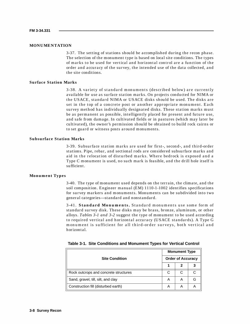
FM 3-34.331
MONUMENTATION
3-37. The setting of stations should be accomplished during the recon phase.The selection of the monument type is based on local site conditions. The typesof marks to be used for vertical and horizontal control are a function of theorder and accuracy of the survey, the intended use of the data collected, andthe site conditions.
Surface Station Marks
3-38. A variety of standard monuments (described below) are currentlyavailable for use as surface station marks. On projects conducted for NIMA orthe USACE, standard NIMA or USACE disks should be used. The disks areset in the top of a concrete post or another appropriate monument. Eachsurvey method has individually designated disks. These station marks mustbe as permanent as possible, intelligently placed for present and future use,and safe from damage. In cultivated fields or in pastures (which may later becultivated), the owner’s permission should be obtained to build rock cairns orto set guard or witness posts around monuments.
Subsurface Station Marks
3-39. Subsurface station marks are used for first-, second-, and third-orderstations. Pipe, rebar, and sectional rods are considered subsurface marks andaid in the relocation of disturbed marks. Where bedrock is exposed and aType C monument is used, no such mark is feasible, and the drill hole itself issufficient.
Monument Types
3-40. The type of monument used depends on the terrain, the climate, and thesoil composition. Engineer manual (EM) 1110-1-1002 identifies specificationsfor survey markers and monuments. Monuments can be subdivided into twogeneral categories—standard and nonstandard.
3-41. Standard Monuments. Standard monuments use some form ofstandard survey disk. These disks may be brass, bronze, aluminum, or otheralloys. Tables 3-1 and 3-2 suggest the type of monument to be used accordingto required vertical and horizontal accuracy (USACE standards). A Type Gmonument is sufficient for all third-order surveys, both vertical andhorizontal.
Table 3-1. Site Conditions and Monument Types for Vertical Control
Site Condition
Monument Type
Order of Accuracy
1 2 3
Rock outcrops and concrete structures C C C
Sand, gravel, till, silt, and clay A A G
Construction fill (disturbed earth) A A A
3-8 Survey Recon

FM 3-34.331
• Type G monument. This classic, standard monument is madecompletely of poured concrete with a disk set in the top of the concrete(Figure 3-1, page 3-10). These procedures and dimensions are for asecond- or higher-order monument. A Type G monument isconstructed by excavating a hole that is 15 centimeters in diameterand 60 centimeters deep. In areas where the maximum frost depth isgreater than 60 centimeters, the hole should be 30 centimeters belowthe frost depth. The disk should be driven onto a pipe, a rod, or anumber 5 rebar that is 120 centimeters long. The pipe, rod, or rebarassembly is then driven into the center of the hole until the top isslightly above the surface. The hole is then filled with concrete, whichmust not cover the disk. The use of pipe, rod, or rebar is optional. Thedisk may be pushed directly into the fresh concrete, but a magnetmust be placed in the concrete if the bar is omitted.
• Type C monument. Sound bedrock is the most desirable location fora BM, as illustrated by Figure 3-2, page 3-10. It provides the moststable setting in terms of underground activity and potentialdisturbances. Always use bedrock when a suitable outcrop exists. Usea star drill to make a hole about 2.5 centimeters wide and 6centimeters deep to receive the shank of the marker. Fill the hole withepoxy resin and insert the disk, with the resin slightly built up aroundthe edge. When a solid bench or ledge is covered with a few feet of topsoil, the subsurface mark should be in the ledge and a concretemonument should be set above it to protrude above the surface.
• Type A monument. Use a Type A rod monument (Figure 3-3,page 3-11) when sound bedrock or substantially stable structures arenot available. The monument provides the extra horizontal stabilityrequired for 3D surveys, which makes the monument a suitable GPSmark. Refer to EM 1110-1-1002 for details on installing a Type Amonument.
NOTE: Type A monuments are used in marshes. Type Gmonuments are used in permafrost areas.
• Precast monument. To eliminate the need for mixing and pouringmonuments at the site, precast monuments may be used if the projectspecifications permit. These precast monuments are fabricated at thebase station or camp and are constructed with the equivalentdimensions listed for poured concrete. If a subsurface mark is
Table 3-2. Site Conditions and Monument Types for HorizontalControl
Site Condition
Monument Type
Order of Accuracy
1 2 3
Rock outcrops and concrete structures C C C
Sand, gravel, till, silt, and clay G G G
Construction fill (disturbed earth) G G G
Survey Recon 3-9

FM 3-34.331
Figure 3-1. Type G Monument
Figure 3-2. Type C Monument
Fro
stde
pth
plus
30cm
60cm
min
imum
Pipe, rod, or rebar(optional)
Concrete
Standard USACEsurvey disk
In-situ soil
120
cm
15 cm
Countersink disk flushwith surface
Epoxy grout
Drill a hole that is2.5 cm in diameter.
Rock orconcrete
3-10 Survey Recon

FM 3-34.331
required, it is placed as identified above with a carefully plumbedprecast monument.
• Commercial monuments. A number of commercial monuments areavailable that can be considered standard monuments. These aregenerally metal or plastic rods (with a disk affixed to the top) that aredriven into the ground.
• RMs. RMs are usually set in the same type of monument as the mainstation, but they can be made smaller. The number of RMs useddepends on the survey method. In triangulation and traversemethods, at least two, but normally three, RMs will be set for eachstation. These marks should be located within 30 meters of the stationand at intervals of about 120° around the station. No subsurfacemarks are used with these marks. RMs should be located where theyare least likely to be disturbed and where direct measurements can bemade to them from the station. It is permissible to use drill holes orchiseled marks in rock outcrops.
• Azimuth marks. Azimuth marks are established in connection withSCPs to furnish an azimuth that will be available to local surveyorsfrom an ordinary ground-level instrument setup. These marks areused in the extension of control from the station. The readings toazimuth marks are observed as part of the traverse method. Azimuthmarks are permanent monuments that are placed in a prominent andsafe location and more than 400 meters but less than 3 kilometersfrom the triangulation station. Prominent, permanent man-made
Figure 3-3. Type A Monument
Ground
Survey disk
Finned rod section
Concrete
15-cm PVC pipeSand
2-cm rod
Aluminum rod sectiondriven to refusalSpiral drive point
16cm
7.5
cm5
cm
In-situ material
Access cover
Survey Recon 3-11

FM 3-34.331
structures may also be used as azimuth marks (for example, the lighton the top of a water or radio-station tower or the cross on a church ina nearby town).
3-42. Nonstandard Monuments. These monuments can take many formsand, if properly installed, provide for a good, permanent control station. Someexamples are—
• Expended shell casings (7.62 to 105 millimeters) embedded into aconcrete post as prepared for standard monuments.
• Sections of rebar or pipe driven into the ground with a concrete collarpoured around the upper 0.3 meter.
To aid in the preservation and to serve as a means of easy recovery ofmonuments, a witness and/or guard post may be established. Witness andguard posts are marked to be readily seen and identified.
• Witness post. A witness post is a sign or stake driven into the groundnext to the station or RM.
• Guard post. A guard post is emplaced around a station that issusceptible to damage from ground traffic. They are generally largewood stock (8 inches by 12 inches by 8 feet) or expended steel (such assections of railroad rails or heavy pipe). They are usually set 1 to1.5 meters into the ground and secured with concrete.
STATION DESCRIPTION AND SKETCH
3-43. The recon party will prepare a description and sketch of all newlyestablished permanent and temporary stations and all stations recovered.Stations recovered, but not used, must also have a description completed. Thedescription and sketch will be done on DA Form 1959 (Figure 3-4) or in anappropriate field book. The field record is done in free hand using verticalgothic lettering. A final DA Form 1959 should be typed and kept with theofficial records.
3-44. Provide a narrative report (compiled at the station site) containing allthe information necessary to expeditiously locate the station. The descriptionshould enable someone totally unfamiliar with the area to go, with certainty,to the immediate vicinity of the station. In conjunction with a sketch, apositive identification of the station and RMs should be possible. Avoidrepetition where possible. The description should be brief (to the point),logical, and include the following information.
Recovery Notes
3-45. The authorized recovery notes are as follows:
• New station. This is a newly established station for which nodescription exists.
• Recovered as described. This is a station that is recovered exactlyas described. All marks are in good condition, the distances anddirections are verified, and the sketch and description are adequate.The statement alone is sufficient for the recon recovery card.Transcribe the old sketch and description onto the new control card.
3-12 Survey Recon

FM 3-34.331
Figure 3-4. Sample of DA Form 1959
SAMPLE
Survey Recon 3-13
FM 3-34.331
• Recovered. This is a recovered station with changes that make theold sketch and description inaccurate or inadequate. Complete a newcard and make a new sketch and/or description of the station. Reportany alterations to the station or RMs and describe the altered marksand new measurements of the referenced distances and directions. Aneffort should be made to improve all sketches and descriptions.
• Not recovered. This is a station for which no positive evidence ofexistence can be found after a diligent search has been made.
• Destroyed. This is a station at which there is positive evidence thatthe station did exist, but the station and its RMs have been somutilated that it cannot be replaced within 1 centimeter of its originalposition. The individual making the recovery and writing thedescription must use judgment in determining the status of a station.A station may be destroyed for precise purposes but still be valuablefor surveys requiring less accurate control (for example, gravimetric,magnetic, or astronomic surveys).
• Reset. This is a station at which the monument and/or station markshave been replaced so that the mark is within 1 centimeter of itsoriginal position. A station is reset only from subsurface and/or RMsthat have not been moved from their original positions. The task ofresetting monuments may be assigned to the recon party.
• Disturbed. This notation is generally used only with reference tovertical control points. It is a station at which the monument isphysically present, but it has been so moved that it has lost its valueas a vertical control point within the accuracy to which it wasoriginally established.
General Location
3-46. This information follows the recovery note. It identifies the location ofthe station area on a map in relation to cities and towns, bridges, and othermajor landmarks. The political subdivision should also be stated.
Route Description
3-47. This describes the route to the station site. The description should startfrom an easily located point such as a public building, a park, a main-roadintersection, or any other permanent landmark that is identifiable both on themap and on the ground. Distances between checkpoints on the route are givenin miles and tenths of miles or kilometers and meters. Changes in routedirection are given as both left or right and east (E), west (W), north (N), orsouth (S).
Station-Site Description
3-48. Describe the exact location of the mark in relation to readily identifiableRMs. List the magnetic azimuth and the distance from the reference point tothe station mark.
3-14 Survey Recon

FM 3-34.331
Station-Mark Description
3-49. Describe the actual mark (for example, drill hole, bronze disk, orchiseled mark in stone) and the exact stamping on the mark (agency, year,and type of station). Note if the station mark is above or below the ground’ssurface.
RMs
3-50. Describe RMs in the same manner as the station mark. Include thedistances and directions measured from the station mark.
Azimuth Mark
3-51. Describe the azimuth mark in the same manner as RMs. The distance isusually approximated rather than measured.
View From Tripod Height
3-52. Describe the field of view from tripod height. For example, the view isunobstructed in all directions except south and the trees (60 feet high,300 feet from the station) obstruct the view between the magnetic azimuths of170° and 215°.
Miscellaneous Information
3-53. List any important information about the station site (which is notcovered elsewhere) in the notes at the bottom of the description. This mayinclude a photo number and mission (if applicable), danger areas, or accessconcerns.
Sketch
3-54. The sketch should be clear and simple and contain only enough detailfor positive identification of the station. In general, it should contain the—
• Features of a permanent nature. Show the features around thestation with enough detail so that they will not be confused with othersimilar features. For example, many road intersections and hilltopslook alike. Extend the sketch slightly so that the characteristicfeatures become evident. When there is little detail available, make arough contour sketch. Use only standard topographic and militarysymbols on the sketches.
• Scope and scale. Judgments on what features are actually requiredto identify the station and the individual’s ability to draw will usuallygovern the scope of a sketch. Normally, a sketch should include thearea within a radius of 200 feet to 1/2 mile. Avoid sketches that coveran area of several miles. In all cases, the termination point of the to-reach site must be on the sketch. The sketch does not need to bedrawn to scale.
• Orientation. The sketch must be oriented to the north.DA Form 1959 has a preprinted arrow to indicate the direction.
Survey Recon 3-15

FM 3-34.331
TRANSPORTATION
3-55. The recon party will use transportation that is organic to the unitaccording to the unit’s TOE and SOPs. When available, due to projectrequirements or customer support, using aircraft will enhance the projectrecon. Helicopters can greatly assist and speed recon efforts (for example,checking routes of travel and lines of sight between stations, selecting andidentifying stations, and determining the scheme for extending surveyingcontrol). If aircraft are used, it is mandatory that the pilots be thoroughlybriefed on the survey project. Complete knowledge of the entire project by thepilots will expedite the field recon and accelerate the progress of the project.
COMMUNICATION
3-56. The recon party has access to radios, according to the unit’s TOE andSOPs. Surveyors use the radios to confirm lines of sight when stations areseparated by great distances. Before using the radios on a survey project, theparty chief will obtain authorized frequencies from the local (customer’s)signal officer. Surveyors will use the radios according to local CEOI andcommunications-electronics standing instruction (CESI). Surveyors will alsofollow the unit’s standing signal instructions (SSI), signal operationinstructions (SOI), and radio-communications procedures. In the event of aconflict, the procedures of the local signal office will take precedence.
LOGISTICS
3-57. The party chief will make arrangements with the customer to ensurethat both fuel and maintenance are available for all vehicles. He will alsoensure that adequate space is available to secure equipment and to performproject administration and field-office computing.
RECON REPORTS
3-58. Upon completion of the field recon, the party chief will submit a reconreport. If the area or the project is large, the project will be divided into phasesand a report will be prepared at the completion of each phase. The reconreport is discussed in detail in Chapter 11.
3-16 Survey Recon

Chapter 4
Datums, Grids, and Coordinate References
The discipline of surveying consists of locating points of interest on thesurface of the earth. Points of interest are defined by spherical or planarcoordinate values that are referenced to a defined mathematical figure. Insurveying, the figure may be an equipotential surface, an ellipsoid ofrevolution, or a plane.
DATUMS
4-1. The earth is an ellipsoid, not a sphere, flattened slightly at the poles andbulging somewhat at the equator. Datums are reference surfaces thatconsider the curvature of the earth for the mathematical reduction of geodeticand cartographic data.
GEOID
4-2. The geoid is the equipotential surface within or around the earth wherethe plumb line is perpendicular to each point on the surface. The geoid isconsidered a MSL surface that is extended continuously through thecontinents. The geoidal surface is irregular due to mass excesses anddeficiencies within the earth. The figure of the earth is considered as a sea-level surface that extends continuously through the continents. The geoid(which is obtained from observed deflections of the vertical) is the referencesurface for astronomical observations and geodetic leveling. The geoidalsurface is the reference system for orthometric heights.
ELLIPSOID
4-3. The WGS is not referenced to a single datum point. It represents anellipsoid whose placement, orientation, and dimensions “best fit” the earth’sequipotential surface that coincides with the geoid. The system was developedfrom a worldwide distribution of terrestrial gravity measurements andgeodetic satellite observations. Several different ellipsoids have been used inconjunction with the WGS ellipsoid. Several ellipsoids are used in US militarymapping. The goal is to eventually refer all positions to the WGS, which has aspecific set of defining parameters, or to a WGS-compatible ellipsoid.Ellipsoids may be defined by a combination of algebraically relateddimensions such as the semimajor and semiminor axes or the semimajor axisand the flattening. Figure 4-1, page 4-2, illustrates the defining parameters ofsome ellipsoids used by NIMA.
PROJECTIONS
4-4. A map projection is the systematic drawing of lines representing themeridians and parallels (the graticule) on a flat surface. Different projections
Datums, Grids, and Coordinate References 4-1

FM 3-34.331
have unique characteristics and serve differing purposes. Projecting thegraticule of the ellipsoid onto a plane depicts the projections. The intersectionsof the graticule are computed in terms of the ellipsoid.
Figure 4-1. Defining Parameters of Ellipsoids
Ellipsoid a (m) b (m) *1/f
Airy 6,377,563.396 6,356,256.910
Australian national 6,378,160 298.25
Bessel 6,377,397.155 299.1528128
Clarke 1866 6,378,206.4 6,356,583.8
Clarke 1880 6,378,249.145 293.465
Everest 6,377,276.345 300.8017
Hough 6,378,270 297
International 6,378,388 297
Modified Airy 6,377,340.189
Modified Everest 6,377,304.063 300.8017
South American 1969 6,378,160 298.25
WGS 72 6,378,135 298.26
*Flattening is the ratio of the difference between the semimajor axis and the semiminor axis of the
spheroid and its major axis and may be stated by the numerical value of the reciprocal of the
flattening (1/f).
a b–( )a
-----------------
Semimajor
axis (a)
Sem
imin
orax
is(b
)
a - b
4-2 Datums, Grids, and Coordinate References

FM 3-34.331
4-5. US military maps use the sexagesimal system of angular measurement(the division of a full circle into 360°) for designating the values of thegraticule. A degree is divided into 60 minutes, and each minute is divided into60 seconds. Parallels are numbered north and south from 0° at the equator to90° at the poles. Meridians are numbered east and west from 0° at the primemeridian to a common 180° meridian. The prime meridian used for USmilitary mapping and charting coincides with the Bureau International deI’Heure defined as zero meridian, located near Greenwich, England.
4-6. The projections used as the framework of all US military maps andcharts are all conformal. Conformability indicates that small areas retaintheir true shape; angles closely approximate their true values; and, at anypoint, the scale is the same in all directions. The following projections, whichshow military grids, are prescribed for US military topographic mapping andcharting:
• Maps at scales larger than 1:500,000 for areas between 80° south and84° north are based on the Universal Transverse Mercator (UTM)Projection.
• Maps of the polar regions (south of 80° and north of 84°) are based onthe Universal Polar Stereographic (UPS) Projection.
These projections are being replaced by the WGS and will be phased out oncethe maps have been reprinted with the WGS.
4-7. The Mercator projection is not normally used for military topographicmaps; however, its description serves as a basis for understanding thetransverse Mercator projection. The Mercator projection can be visualized as aspheroid projected onto a cylinder tangent to the equator and parallel to thepolar axis (Figure 4-2, page 4-4). When the cylinder is opened and flattened, adistortion appears. The distortion becomes more pronounced as the distancefrom the equator increases. The Mercator projection is transversed by rotatingthe cylinder again until the spheroid is parallel to a second axis (themeridian), which is then open and flattened (Figure 4-3, page 4-5). Formilitary purposes and to minimize distortion, the transverse Mercatorprojection uses 60 longitudinal zones, each 6° wide.
4-8. Most military operations assume that map and ground distances areequivalent. However, in certain geodetic and artillery operations, where longdistances are involved and the accuracy of results is essential, it is necessaryto correct for the difference between distances on the map and distances onthe ground. This is done by using scale factors from prepared tables orformulas. For the transverse Mercator projection, the scale factor is 1.00000(unity) at the lines between each zone, decreasing inwardly to 0.9996 at thecentral meridian (CM) and increasing outwardly to about 1.0010 near thezone boundaries at the equator.
GRIDS
4-9. Grids are applied to maps to provide a rectangular system for referencingand making measurements. There is a definite relationship between the gridand the graticule, so that a corresponding geographic position can bedetermined for each grid position. Military grids consist of parallel lines
Datums, Grids, and Coordinate References 4-3

FM 3-34.331
Figure 4-2. Mercator Projection
Spheroid and cylinder oncommon axis and tangentalong the equator.
Origin of projecting lines(3/4 of the way backalong the diameter).
Developmentsurface (cylinder)
Flattened cylinder with developed projection.
4-4 Datums, Grids, and Coordinate References

FM 3-34.331
Figure 4-3. Transverse Mercator Projection
Axis of spheroid normal toaxis of cylinder; spheroidtangent to cylinder along ameridian.
Development surface(cylinder)
Origin of projecting lines(3/4 of the way back alongthe diameter).
Flattened cylinder withdeveloped projection.
Datums, Grids, and Coordinate References 4-5

FM 3-34.331
intersecting at right angles and forming a regular series of squares. Thenorth-south lines are called eastings and the east-west lines are callednorthings. Each grid line is one of an even-interval selection of measurementunits. The interval is selected according to the map scale. The military preferto use the UTM grid for areas between 80° south and 84° north.
COORDINATE REFERENCES
4-10. Coordinates may be transformed from one grid system to another (forexample, between the Lambert grid and the UTM grid or between differentgrid zones). The preferred method is to transform the grid coordinates fromthe first grid system to geographic positions. Then transform the geographicpositions to the grid coordinates of the second grid system. This method doesnot change the datum.
THE US MILITARY GRID-REFERENCE SYSTEM
4-11. The US Military Grid-Reference System (MGRS) is designed for usewith UTM grids. For convenience, the earth is generally divided into 6° by 8°geographic areas, each of which is given a unique grid-zone designation. Theseareas are covered by a pattern of 100,000-meter squares. Two letters (calledthe 100,000-meter-square letter identification) identify each square. Thisidentification is unique within the area covered by the grid-zone designation.
4-12. The MGRS is an alphanumeric version of a numerical UTM gridcoordinate. Thus, for that portion of the world where the UTM grid is specified(80° south to 84° north), the UTM grid-zone number is the first element of amilitary grid reference. This number sets the zone longitude limits. The nextelement is a letter that designates a latitude bond. Beginning at 80° south andproceeding northward, 20 bands are lettered C through X. In the UTM portionof the MGRS, the first three characters designate one of the areas within thezone dimensions.
4-13. A reference that is keyed to a gridded map (of any scale) is made bygiving the 100,000-meter-square letter identification together with thenumerical location. Numerical references within the 100,000-meter squareare given to the desired accuracy in terms of the easting and northing gridcoordinates for the point.
4-14. The final MGRS position coordinate consists of a group of letters andnumbers that include the following elements:
• The grid-zone designation.• The 100,000-meter-square letter identification.• The grid coordinates (also referred to as rectangular coordinates) of
the numerical portion of the reference, expressed to a desiredrefinement.
The reference is written as an entity without spaces, parentheses, dashes, ordecimal points. Examples are as follows:
• 18S (locating a point within the grid-zone designation).• 18SUU (locating a point within a 100,000-meter square).• 18SUU80 (locating a point within a 10,000-meter square).
4-6 Datums, Grids, and Coordinate References

FM 3-34.331
• 18SUU8401 (locating a point within a 1,000-meter square).• 18SUU836014 (locating a point within a 100-meter square).
4-15. To satisfy special needs, a reference can be given to a 10-meter squareand a 1-meter square. Examples are as follows:
• 8SUU83630143 (locating a point within a 10-meter square).• 18SUU8362601432 (locating a point within a 1-meter square).
4-16. There is no zone number in the polar regions. A single letter designatesthe semicircular area and the hemisphere. The letters A, B, Y, and Z are usedonly in the polar regions, and their presence in an MGRS (with the omission ofa zone number) designates that the coordinates are UPS. An effort is beingmade to reduce the complexity of grid reference systems by standardizing asingle, worldwide grid reference system (for example, WGS).
GEOGRAPHIC COORDINATES
4-17. The use of geographic coordinates as a system of reference is acceptedworldwide. It is based on the expression of position by latitude (parallels) andlongitude (meridians) in terms of arc (degrees, minutes, and seconds) referredto the equator (north and south) and a prime meridian (east and west).
4-18. The degree of accuracy of a geographic reference (GEOREF) isinfluenced by the map scale and the accuracy requirements for plotting andscaling. Examples of GEOREFs are as follows:
• 40° N 132° E (referenced to degrees of latitude and longitude).• 40°21′ N 132°14′ (referenced to minutes of latitude and longitude).• 40°21′12″ N 132°14′18″ E (referenced to seconds of latitude and
longitude).• 40°21′12.4″ N 132°14′17.7″ E (referenced to tenths of seconds of
latitude and longitude).• 40°21′12.45″ N 132°14′17.73″ E (referenced to hundredths of seconds
of latitude and longitude).
4-19. US military maps and charts include a graticule (parallels andmeridians) for plotting and scaling geographic coordinates. Graticule valuesare shown in the map margin. On maps and charts at scales of 1:250,000 andlarger, the graticule may be indicated in the map interior by lines or ticks atprescribed intervals (for example, scale ticks and interval labeling at thecorners of 1:50,000 at 1′ [in degrees, minutes, and seconds] and againevery 5′).
THE WORLD GEOREF SYSTEM
4-20. The World GEOREF System is used for position reporting. It is not amilitary grid and, therefore, does not replace existing military grids. It is anarea-designation method used for interservice and interallied positionreporting for air-defense and strategic air operations. Positions are expressedin a form that is suitable for reporting and plotting on any map or chart(graduated in latitude and longitude) regardless of the map projection.
Datums, Grids, and Coordinate References 4-7

FM 3-34.331
4-21. The system divides the surface of the earth into quadrangles, the sidesof which are specific arc lengths of longitude and latitude. Each quadrangle isidentified by a simple systematic letter code giving positive identification withno risk of ambiguity.
4-22. There are 24 longitudinal zones (each 15° wide) extending eastwardfrom the 180° meridian around the globe through 360° of longitude. Thesezones are lettered from A to Z inclusive. There are 12 bands of latitude (each15° high) extending northward from the south pole. These bands are letteredfrom A to M inclusive, northward from the south pole.
4-23. Each 15° quadrangle is subdivided into 15, 1° zones of longitudeeastward from the western meridian of the quadrangle. These 1° units arelettered from A to Q inclusive. Each 15° quadrangle is also subdivided into 15,1° bands of latitude northward from the southern parallel of the quadrangle.These bands are lettered from A to Q inclusive. Four letters may now identifya 1° quadrangle anywhere on the earth’s surface.
4-24. Each 1° quadrangle is divided into 60′ of longitude (numbered eastwardfrom its western meridian) and 60′ of latitude (numbered northward from itssouthern parallel). This direction of numbering is used wherever the 1°quadrangle is located. It does not vary, even though the location may be westof the prime meridian or south of the equator. A unique reference for definingthe position of a point to an accuracy of 1′ in latitude and longitude (forexample, 2 kilometers or less) is given by quoting four letters and fournumerals. The four letters identify the 1° quadrangle. The first two numeralsare the number of minutes of longitude. The last two numerals are thenumber of minutes of latitude. If the number of minutes is less than 10, thefirst numeral will be a zero (for example, 04).
4-25. Each of the 1° quadrangles may be further divided into decimal parts(tenths or hundreths) eastward and northward. Thus, four letters and sixnumerals will define a location to 0.1′ and four letters and eight numerals willdefine a location to 0.01′.
GPS REFERENCE SYSTEMS
4-26. To fully understand GPS and the positional information, it is importantto understand the reference system on which it is based. GPS satellites arereferenced to the WGS-84 ellipsoid. The absolute positions that are obtaineddirectly from the GPS measurements are based on the 3D, earth-centeredWGS-84 ellipsoid. Coordinate outputs are on a Cartesian system (X, Y, and Z)relative to an earth-centered, earth-fixed (ECEF) rectangular coordinatesystem having the same origin as the WGS-84 ellipsoid (geocentric). WGS-84Cartesian coordinates are then converted into WGS-84 ellipsoid coordinates(latitude, longitude, and height). The GPS uses the WGS-84 ellipsoid forgeodetic survey purposes. The GPS routinely provides differential positionalresults on the order of 1 part per million (ppm), compared to the acceptedresults of 1:300,000 for NAD 83 and approximately 1:100,000 for NAD 27.
HORIZONTAL-POSITIONING DATUMS
4-27. One application of DGPS surveying is densifying project control.Densification is usually done relative to an existing datum (NAD 27, NAD 83,
4-8 Datums, Grids, and Coordinate References

FM 3-34.331
or local). Even though GPS measurements are made relative to the WGS-84ellipsoid coordinate system, coordinate differences (such as baseline vectors)on this system can be used directly on any user datum. Minor variationsbetween these datums will be minimal when GPS data are adjusted to fitbetween local datum stations. Such assumptions may not be valid when high-order National Geodetic Reference System (NGRS) network densification isbeing performed.
NOTE: NIMA provides datum transformation parameters to manymore datums (including local).
NAD 27
4-28. NAD 27 is a horizontal datum based on a comprehensive adjustment ofthe US National Control Network of traverse and triangulation stations.NAD 27 is a best fit for CONUS. The relative precision between initial-pointmonuments of NAD 27 is by definition 1:100,000, but coordinates on any givenmonument in the network contain errors of varying degrees. As a result,relative accuracy between points on NAD 27 may be far less than 1:100,000.
NAD 83
4-29. NAD 83 uses many more station observations than NAD 27 to readjustthe US National Control Network. NAD 83 has an average precision of1:300,000. NAD 83 is based on the Geodetic Reference System (GRS) of 1980(GRS-80), earth-centered reference ellipsoid and, for most practical purposes,is equivalent to WGS 84.
High-Accuracy Reference Networks Survey Datum
4-30. The nationwide horizontal reference network was redefined in 1983 andreadjusted in 1986 by the NGS. Since that time, several states and the NGShave begun developing high-accuracy reference networks (HARNs) forsurveying, mapping, and related spatial-database projects. These networks(developed exclusively with a GPS) are accurate to 1 part in 1,000,000.
ORTHOMETRIC ELEVATIONS
4-31. Orthometric elevations correspond to the earth’s irregular geoidalsurface and are based on tidal fluctuations of the MSL at a specific location.Measured DEs, based on spirit leveling, are generally relative to geoidalheights. The DEs between two points are called orthometric differences.Orthometric heights for CONUS are generally referenced to NGVD 29 orNAVD 88.
WGS-84 ELLIPSOID HEIGHTS
4-32. GPS-determined heights are referenced to an idealized mathematicalellipsoid. This WGS-84 ellipsoid differs significantly from the geoid; thus, GPSheights are not the same as orthometric heights. Due to significant variationsin the geoid (even over small distances), elevations cannot be directly equatedto orthometric differences. For small project areas where the geoid remainsfairly constant, the relationship between orthometric and ellipsoid heights canbe obtained from computer modeling or local geoid modeling. Local geoid
Datums, Grids, and Coordinate References 4-9

FM 3-34.331
modeling requires connecting to a sufficient number of existing orthometricBMs from which the elevations of known points can be best fit by adjustment.
COORDINATE CONVERSION
4-33. Numerous mathematical techniques have been developed to convertcoordinates between NAD 83 and NAD 27. These techniques include a varietyof multiple-parameter and multiple-regression transformation equations.Each technique has advantages and disadvantages in terms of accuracy,consistency, and complexity. To eliminate these inconsistencies, the USACETopographic Engineering Center (TEC) configured a comprehensivecoordinate-conversion software program called Corps Conversion (Corpscon).Corpscon is the standard for topographic survey conversions, but newerprograms are available. Additional technical information and authorizedsoftware programs can be obtained from TEC or NIMA web sites.
4-10 Datums, Grids, and Coordinate References

Chapter 5
Conventional Survey-Data Collection
Theodolites and transits are instruments designed to measure horizontaland vertical angles. As optical instruments progressed, the development ofoptics allowed the telescope to become shortened to the point that theoptics could be rotated 360° horizontally. This act of turning the telescopehas sped up work and permitted the qualitative review of sighting andinstrument errors.
5-1. Surveys are usually performed to collect data that can be drawn to scaleand plotted on a plan or map or to lay out dimensions shown on a design.Measurements for both types of surveys must be referenced to a common basefor X, Y, and Z dimensions. The establishment of a base for horizontal andvertical measurements is known as a control survey. Conventional controlsurveys use two fundamental measurements—angle determination anddistance measurement.
ANGLE DETERMINATION
5-2. Horizontal angles are usually turned (or deflected) to the right or left.The three types of angle measurements are as follows:
• Interior angles. If angles in a closed figure are to be measured, theinterior angles are normally read. When all interior angles have beenrecorded, the accuracy of the work can be determined by comparingthe sum of the abstracted angles with the computed value for theclosed loop (Figure 5-1, page 5-2).
• Deflection angles. In an open traverse (Figure 5-2, page 5-2), thedeflection angles are measured from the prolongation of the backsightline to the foresight line. The angles are measured either to the left orto the right. The direction must be shown along with the numericalvalue.
• Vertical angles. Vertical angles can be referenced to a horizontal orvertical line (Figure 5-3, page 5-3). Optical-micrometer theodolitesmeasure vertical angles from the zenith (90° or 270° indicate ahorizontal line). Zenith and nadir are terms describing points on asphere. The zenith point is directly above the observer, and the nadirpoint is directly below the observer. The observer, the zenith, and thenadir are on the same vertical line.
SECTION I - FUNDAMENTALS
Conventional Survey-Data Collection 5-1

FM 3-34.331
OPTICAL THEODOLITES
5-3. It is difficult to precisely set the angle values on the plates of an opticaltheodolite. Angles are determined by reading the initial and the finaldirections and then determining the angular difference between the twodirections. Optical theodolites are generally very precise. The opticaltheodolite used by Army topographic surveyors (Figure 5-4, page 5-4) readsdirectly to 1″ and by estimation to 0.1″. Figure 5-4 shows that the micrometerwas turned to read an even 10″. This is done by moving the grid lines intocoincidence, and then the micrometer scale reading (02′44″) is added to thecircle reading (94°10′) to give the resulting angle of 94°12′44″. If severalsightings are required for precision purposes, distribute the initial settingsaround the plate circle to minimize the effect of circle-graduation distortions.Table 5-1, pages 5-5 and 5-6, illustrates the circle settings for 2 through 16positions for a 1″ theodolite.
Figure 5-1. Interior Angles on a Closed Traverse
Figure 5-2. Deflection Angles Shown on an Open Traverse
Station C
Station D
Station E
Station A
Station B
Exterior angle =272°55′
87°05′
120°
108°
105°
118°
17°51′R22°18′R
38°06′L
6 + 33
3 + 71
1 + 43
LEGEND:L = leftR = right
5-2 Conventional Survey-Data Collection

FM 3-34.331
OBSERVATION PRECAUTIONS
5-4. Because of the high-accuracy requirements for second- and third-orderobservations, constant precautions are necessary to counteract all errorsources. The party chief should periodically inspect the performance of allobserving parties. A good observer achieves the full potential of theinstrument at all times. Signals and targets should be precisely bisected. Verylittle spread (three or fewer of the smallest increments marked on themicrometer) between the direct and reverse measurements should beconsistently obtained. Proficiency can be attained only by a careful study of allfactors affecting the accuracy of theodolite observations. Efforts should bemade to eliminate all known error sources. Observation precautions aresummarized as follows:
• Instrument check. Check the instruments and targets for stability.If an instrument is not stable, all other refinements are useless.
• Instrument adjustment. Pay careful attention to the parallax andthe inclination of the horizontal circle plate. Errors introduced by theparallax and the inclination cannot be eliminated.
• Signal and target centering. Plumb signals and targets directlyover the SCP. Carefully aim signals and targets towards the observingstation.
5-5. Do not disturb the instrument while observing a position by releveling orstriking the instrument or its support. Avoid any lateral thrust to a clamp, a
Figure 5-3. Reference Directions for Vertical Angles (Horizontal, Zenith, and Nadir)
Horizondirection
Horizondirection
Zenith angle
Plus vertical angle
Minus vertical angle
Nadir angle
Nadir direction
Theodolite
90°
Conventional Survey-Data Collection 5-3

FM 3-34.331
Figure 5-4. Optical Theodolite
9 3 0 9 45 4 3 2 1 0
2′40″ 2′50″
Vertical angle = 94°12′44″
Microscopefocusing knob
Micrometerknob
Micrometerassembly
Plate level
Inverter knob
Horizontal clamp
Spring housingassembly
Optical plummet
Circular level Tribrach
Tribrach lockinglever
Horizontal-circledrive knob
Horizontal-circledrive cover
Horizontal clamp knob
Collimation slow-motion screw
Spring housingassembly
Sunshade
Reticle-illumination knob
Telescope
5-4 Conventional Survey-Data Collection

FM 3-34.331
Table 5-1. Circle Settings for a 1 ″ Theodolite
Number 5 ′′′′ Micrometer Drum 10 ′′′′ Micrometer Drum Circle Wild T-3 MicrometerTwo1 NA NA NA 0° 00′ 10″ NA NA NA2 NA NA NA 90° 05′ 40″ NA NA NAFour1 0° 00′ 40″ 0° 00′ 10″ 0° 00′ 15″2 45° 01′ 50″ 45° 02′ 40″ 45° 02′ 45″3 90° 03′ 10″ 90° 05′ 10″ 90° 04′ 15″4 135° 04′ 20″ 135° 07′ 40″ 135° 20′ 45″Six1 0° 00′ 10″ 0° 00′ 10″ 0° 00′ 15″2 30° 01′ 50″ 30° 01′ 50″ 30° 02′ 35″3 60° 03′ 30″ 60° 03′ 30″ 60° 00′ 50″4 90° 00′ 10″ 90° 05′ 10″ 90° 04′ 15″5 120° 01′ 50″ 120° 06′ 50″ 120° 00′ 35″6 150° 03′ 30″ 150° 08′ 30″ 150° 20′ 50″Eight1 0° 00′ 40″ 0° 00′ 10″ 0° 00′ 10″2 22° 01′ 50″ 22° 01′ 25″ 22° 00′ 25″3 45° 03′ 10″ 45° 02′ 40″ 45° 02′ 35″4 67° 04′ 20″ 67° 03′ 55″ 67° 00′ 50″5 90° 00′ 40″ 90° 05′ 10″ 90° 04′ 10″6 112° 01′ 50″ 112° 06′ 25″ 112° 00′ 25″7 135° 03′ 10″ 135° 07′ 40″ 135° 20′ 35″8 157° 04′ 20″ 157° 08′ 55″ 157° 00′ 50″Twelve1 0° 00′ 40″ 0° 00′ 10″ 0° 00′ 10″2 15° 01′ 50″ 15° 01′ 50″ 15° 00′ 25″3 30° 03′ 10″ 30° 03′ 30″ 30° 02′ 35″4 45° 04′ 20″ 45° 05′ 10″ 45° 00′ 50″5 60° 00′ 40″ 60° 06′ 50″ 60° 00′ 10″6 75° 01′ 50″ 75° 08′ 30″ 75° 00′ 25″7 90° 03′ 10″ 90° 00′ 10″ 90° 04′ 35″8 105° 04′ 20″ 105° 01′ 50″ 105° 00′ 50″9 120° 00′ 40″ 120° 03′ 30″ 120° 00′ 10″10 135° 01′ 50″ 135° 05′ 10″ 135° 00′ 25″11 150° 03′ 10″ 150° 06′ 50″ 150° 20′ 35″12 165° 04′ 20″ 165° 08′ 30″ 165° 00′ 50″Sixteen1 0° 00′ 40″ 0° 00′ 10″ 0° 00′ 10″2 11° 01′ 50″ 11° 01′ 25″ 11° 00′ 25″3 22° 03′ 10″ 22° 02′ 40″ 22° 00′ 35″4 33° 04′ 20″ 33° 03′ 55″ 33° 00′ 50″5 45° 00′ 40″ 45° 05′ 10″ 45° 02′ 10″6 56° 01′ 50″ 56° 06′ 25″ 56° 00′ 25″7 67° 03′ 10″ 67° 07′ 40″ 67° 00′ 35″8 78° 04′ 20″ 78° 08′ 55″ 78° 00′ 50″
Conventional Survey-Data Collection 5-5

FM 3-34.331
tangent screw, or the electric switch. Other operational precautions foraccurate observations are as follows:
• Repoint on the initial target after each circle setting.• Check the plate level frequently.• Protect the instrument from wind, sunshine, and precipitation.
5-6. When all other known precautions have been taken, one of the principalcauses of error is horizontal refraction. Sometimes elevating the signal willreduce the effects of horizontal refraction, but often the only solution withoutaltering the traverse is to reobserve the target under different atmosphericconditions.
HORIZONTAL-DIRECTION RECORDINGS
5-7. Procedures for recording horizontal directions are the same for all ordersof accuracy. Record horizontal directions on a DA Form 4253 (Figure 5-5) orany authorized single-sheet recording forms. When operating the AISI, usethe appropriate recording media. In all cases, documentation should becompleted in the field. Each time an SCP is occupied, the followinginformation should be recorded:
• Instrument make, model, and serial number.• Instrument operator’s name.• Recorder’s name.• Weather description.
■ Temperature.■ General atmospheric condition.■ Wind.
• Designation of the occupied station.■ Full station name.■ Year established.■ Name of the agency on the disk.
5-8. The recording form should include the above information for each stationobserved. If an instrument, signal, or target is set eccentric to a station (notplumbed directly over the station mark), that item will be sketched on therecording form. The sketch should include the distance and the directions thatthe eccentric item is from the station. When intersection stations areobserved, the exact part of the point observed must be recorded and shown onthe sketch.
9 90° 00′ 40″ 90° 00′ 10″ 90° 04′ 10″10 101° 01′ 50″ 101° 01′ 25″ 101° 00′ 25″11 112° 03′ 10″ 112° 02′ 40″ 112° 00′ 35″12 123° 04′ 20″ 123° 03′ 55″ 123° 00′ 50″13 135° 00′ 40″ 135° 05′ 10″ 135° 02′ 10″14 146° 01′ 50″ 146° 06′ 25″ 146° 00′ 25″15 157° 03′ 10″ 157° 07′ 40″ 157° 00′ 35″16 168° 04′ 20″ 168° 08′ 55″ 168° 00′ 50″
Table 5-1. Circle Settings for a 1 ″ Theodolite (continued)
Number 5 ′′′′ Micrometer Drum 10 ′′′′ Micrometer Drum Circle Wild T-3 Micrometer
5-6 Conventional Survey-Data Collection
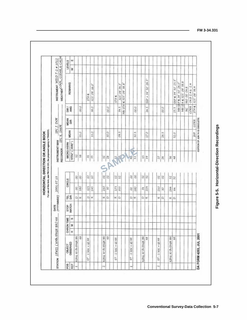
FM 3-34.331
Fig
ure
5-5.
Hor
izon
tal-D
irect
ion
Rec
ordi
ngs
SAMPLE
Conventional Survey-Data Collection 5-7

FM 3-34.331
5-9. Numbers and letters should be approximately half the height betweenlines. The recording should be centered in the block and on the bottom line ofthe block. All figures must be neat and legible. There should be no erasures orobscuring of the original figures. Original numbers may be crossed out byusing a single diagonal line through the numbers. The corrected numbersshould be written above the original entry. The person making the correctionwill initial above and to the right of the original entry and within the blockand will explain the reason for the correction in the remarks column. Noposition will be voided or rejected on any recording media, except in the case ofbumping the instrument or stand, which causes the instrument to becomeunleveled. If the instrument is observed to be unleveled, make a note on therecording media in the remarks column stating that the instrument was notleveled and why. All recordings will be done with black ink. Directions will beentered in the remarks column (in degrees, minutes, and seconds).
5-10. The observer will check every computation on each page or sheet. Theobserver will verify the computation with a light, visible tick mark to theupper right of the computed numbers or will correct the numbers as describedabove. The observer will confirm that all computed numbers on the page havebeen checked by initialing at the bottom right corner of the page.
5-11. If a recording book is used, make an index (on the appropriate page) ofthe stations from which observations were made and recorded. An index isalso required for all other recording media, indicating where to locateobservations from any occupied SCP.
HORIZONTAL-DIRECTION ABSTRACTS
5-12. Second-order horizontal-observation specifications require that anabstract of horizontal directions be compiled for every station at whichhorizontal directions have been observed. DA Form 1916 (Figure 5-6) will becompleted before leaving the SCP. Third-order horizontal observations requirethat the horizon closure, the corrected station angle, and the correctedexplement angle be recorded before leaving the SCP. Readings will be enteredopposite the proper circle position, as indicated in the field notes. The degreesand minutes for each direction are entered one time at the top of each column,and the seconds are entered for each circle position.
5-13. Record all observed positions on the DA Form 1916. If two or moreobservations have been made for the same target, list all the observations inthe same box and determine the mean for that position.
5-14. Examine the listed positions. For any position that appears to varygreatly from the apparent mean of all the positions, check the computations inthe field-recording book or other recording media. Be alert for a change in theminutes of the computed directions (angles) in the field data. Reject anypositions that vary widely from the mean and then reobserve the positions.Enclose any values that are rejected by observation in parentheses and followwith “Ro.”
5-15. Compute the mean of the observed positions. Round the mean value of adirection to the nearest 0.1″ if a 1″ instrument was used for observation.Reject all observations that differ from the mean by more than the rejectionlimit. Enclose any rejected observations in parentheses and follow with “R1.”
5-8 Conventional Survey-Data Collection

FM 3-34.331
R1 indicates that the value was rejected using the first mean value. Therejection limit will be applied to each observation with the same amount ofaccuracy as when the mean was determined.
5-16. Reobserve any rejected positions and determine a new mean. Reapplythe rejection limit. Enclose any positions still exceeding the rejection limit inparentheses and follow with “R2.” R2 indicates that the value was rejectedusing the second mean value. Ensure that sufficient acceptable positionsremain.
Figure 5-6. Abstracting Horizontal Directions
SAMPLE
Conventional Survey-Data Collection 5-9

FM 3-34.331
5-17. Do not reject any reading if it is within the rejection limits, unless it wasrejected at the time of observation. If a value was rejected at the time ofobservation, check the field notes for the observer’s reason for rejection. Oncea value is rejected, it cannot be used again.
5-18. Do not use the mean of the readings if one of two or more readings on aposition is outside the rejection limits. Use only the reading that is within therejection limits. If two readings are outside the rejection limits (one is high,the other is low, and the mean is within the limits), the readings must berejected. If there is a progressive change in the values of the positions of adirection or if the mean of the first half of the positions differs appreciablyfrom the mean of the last half of the positions, attempt to observe anothercomplete set of positions before leaving the SCP.
VERTICAL-OBSERVATION RECORDINGS
5-19. Recording vertical observations (zenith distances [ZDs]) is the same forall orders of accuracy. Vertical observations are recorded on DA Form 5817-R(Figure 5-7), an authorized single-sheet recording form, or appropriate mediawhen operating the AISI. In all cases, complete documentation will beperformed in the field. In addition to the recording requirements, record thefollowing information:
• The HI above the station (recorded to the nearest 0.01 meter).• A sketch of the observed target (that shows the point observed on the
target) at the bottom of the object-observed column.• The height of the observed target (HT) above the station being
observed (recorded to the nearest 0.01 meter).• A sketch showing any target’s adjoining stations. This sketch will be
drawn in the bottom of the remarks column. All possible points thatmay be observed will be measured and recorded to the nearest0.01 meter.
5-20. During vertical observations, the time of the first observation of the firstposition and the time of the last observation of the last position are recorded.The times are recorded to the nearest whole minute.
VERTICAL-OBSERVATION ABSTRACTS
5-21. Vertical observations are abstracted onto DA Form 1943 (Figure 5-8,page 5-12) at the station site by the observing party. Targets or signals shownto other stations are sketched and dimensioned at the bottom of the form. If atarget or signal is changed during the day, the time of the change and the newdimensions are also entered.
5-22. Vertical observations recorded as vertical angles are converted to ZDsbefore abstracting. The ZDs are abstracted, including the times of theobservations. The abstracted ZDs are meaned and reduced to corrected ZDs byapplying the reduction to line-joining stations. The following formula is usedto determine the reduction in seconds:
where—
s = slope distance between stations (in kilometers)
Reduction in secondsHI HT–( )sin mean ZD
s 1″sin--------------------------------------------------------=
5-10 Conventional Survey-Data Collection

FM 3-34.331
SAMPLE
Fig
ure
5-7.
Rec
ordi
ngO
bser
ved
ZD
s
Conventional Survey-Data Collection 5-11

FM 3-34.331
Figure 5-8. Abstracting Zenith Distances
SAMPLE
5-12 Conventional Survey-Data Collection

FM 3-34.331
5-23. This formula will also be applied to the vertical observations performedat the station at the other end of the observed line (reciprocal observations).The total length of the lines is multiplied by 0.46 (a constant based on theearth’s curvature). Subtract 180° from the sum of the two corrected ZDs todetermine the observed difference expressed as minutes of arc. If the twovalues differ by more than 1′ of arc, perform a second set of reciprocal ZDobservations. Differences exceeding 1′ of arc are normally due to errors inobservations or unusual refraction in the atmosphere (poor observingconditions).
DISTANCE MEASUREMENT
5-24. The distance between two points can be horizontal, slope, or vertical. Atape measure or an EDM device can measure horizontal and slope distances.In surveying, horizontal-distance measurements are always required. Adistance measured on a slope can be trigonometrically converted to itshorizontal equivalent by using the slope angle or vertical DE. Figure 5-9illustrates a basic example of the geometry used to determine the horizontaldistance of a measurement over uneven ground.
OBSERVATION PRECAUTIONS
5-25. Distances measured using an EDME are subject to the same errors asdirection measuring equipment. The errors also include instrumentalcomponent errors. Instrumental errors are usually described as a number ofmillimeters plus a number of ppm. The accuracy of the infrared EDME AISI is±(5 millimeters + 5 ppm). The ppm accuracy factor can be thought of in termsof millimeters per kilometer, as there are 1 million millimeters in 1 kilometer.This means that 5 ppm equal 5 millimeters per kilometer. If the AISI is in theD-bar mode, the accuracy is ±(2 millimeters + 3 ppm). Errors introduced bymeteorological factors must be accounted for when measuring distances of500 meters or more. Accurate ambient temperature and barometric pressure
Figure 5-9. Geometry of an EDM (Basic Example)
Ground
Station A
Station B
EDM
HI (measured)
Elevation at Station B = elevation at Station A + HI ± V - HT
HT (measured)
V(S sin α)
Prism
S (measured)
H(S cos α)α
LEGEND:V = vertical distanceH = horizontal distanceS = slope distance
Conventional Survey-Data Collection 5-13

FM 3-34.331
must be measured. An error of 1 degree Celsius (C) causes an error of 0.8 ppmfor infrared distances. An error of 3 millimeters of mercury causes an error of0.9 ppm in distance.
INSTRUMENT CONSTANTS
5-26. Although manufacturers provide instrument and prism constants, it isessential that instrument constants be verified under actual operatingconditions, especially for precise surveys. The following factors must beconsidered:
• The use of a prism typically provides an indicated distance longerthan the true value. Applying a negative correction will compensatefor this effect. Each prism should have its own constant or correctiondetermined individually, and a master file should be maintained.
• An instrument constant can be either positive or negative and maychange due to the phase shifts in the circuitry. Therefore, a positive ora negative correction may be required.
• The algebraic sum of the instrument and the prism constants arereferred to as the total constant. The correction for the total constant(equal in magnitude but opposite in sign) is referred to as the total-constants correction, from which the instrument or prism constant canbe computed if one or the other is known.
UTM SCALE FACTOR
5-27. The scale factor (a computed factor) affects the measured distance. Thescale factor for a particular UTM zone is solely dependent on the location ofthe survey in relation to its east-west distance from the UTM-zone CM. Thesezones are 6° wide and originate at 0° Greenwich meridian. North-southdistances within the zone have no influence on the scale factor. The scalefactor at the CM of UTM zones is 0.9996. The UTM scale factor toward theeast and west from the CM increases to approximately 1.0004. Data-reductionprocedures using the scale factor are necessary for precise surveys.
CURVATURE OF REFRACTION CORRECTION
5-28. Distance measurements are not on a straight line. The earth’scurvature and gravity affect the path traveled by the light beam. For ameasured distance of 1 kilometer, the beam changes its path by nearly7 centimeters. An approximate estimate of this effect is expressed by thefollowing formula:
where—
VD = the vertical difference
0.0675 = the estimated effect on the path traveled by light
km = the distance in kilometers (for example, 0.9 or 1.2)
VD 0.0675 km2
=
5-14 Conventional Survey-Data Collection

FM 3-34.331
EDME RECORDING
5-29. Distances measured by EDME will be recorded on authorized single-sheet recording forms. Figure 5-10 shows a completed DA Form 5819. If theAISI is used, the appropriate recording media is authorized.
ELECTRONIC TOTAL STATIONS
5-30. Electronic theodolites operate in a manner similar to opticalinstruments. Angle readings can be to 1″ with precision to 0.5″. Digitalreadouts eliminate the uncertainty associated with reading and interpolating
Figure 5-10. Recording Electronically Measured Distances
SAMPLE
Conventional Survey-Data Collection 5-15
FM 3-34.331
scale and micrometer data. The electronic angle-measurement systemeliminates the horizontal- and vertical-angle errors that normally occur inconventional theodolites. Measurements are based on reading an integratedsignal over the surface of the electronic device that produces a mean angularvalue and completely eliminates the inaccuracies from eccentricity and circlegraduation. These instruments also are equipped with a dual-axiscompensator, which automatically corrects both horizontal and vertical anglesfor any deviation in the plumb line. An EDM device is added to the theodoliteand allows for the simultaneous measurements of the angle and the distance.With the addition of a data collector, the total station interfaces directly withonboard microprocessors, external PCs, and software. The ability to performall measurements and to record the data with a single device hasrevolutionized surveying. Army topographic surveyors use the AISI, which isaddressed in detail in Section III.
5-31. A target is generally considered to be a nonilluminating signal. Thereare two general types of targets—tripods and poles. Both target types mayincorporate variations. Targets are constructed of wood or metal frameworkswith cloth covers. For easy bisection, a target should be as narrow as possiblewithout sacrificing distinctness. Triangular-shaped targets are the easiest tobisect. Square- and rectangular-shaped targets are the second easiest tobisect. Round targets are the hardest to bisect due to problems in pointingduring repeated observations. Round targets should be avoided wheneverpossible. A target that subtends an angle of 4″ to 6″ of arc is easy to bisect.Since 1″ of arc equals 0.5 centimeter at a l-kilometer distance, 6″ of archequals 3 centimeters at a 1-kilometer distance and 30 centimeters at a10 kilometer distance. Under adverse lighting conditions, the target widthwill have to be increased. To make a target readily visible against both lightand dark backgrounds, use material constructed of alternating bands of redand white or orange and yellow. Flags may be added or the background maybe filled with blaze-orange cloth to contrast the target. All cloth used on thetargets should be slashed after construction to minimize wind resistance andto avoid pilfering in areas where cloth may be valuable.
OPTICAL-THEODOLITE TARGET SET
5-32. The optical-theodolite target set is precise-survey equipment that isgenerally used for short traverse lines (about 4 kilometers or less). This targetset (Figure 5-11) consists of a lower and an upper group. The lower groupconsists of a tribrach with a three-screw leveling head, a circular bubble, andan optical plumbing device. The upper group contains a plate with threetriangles; a long, level vial; and a lighting attachment. The upper group isremovable and is interchangeable with a theodolite.
SECTION II - TARGETS
5-16 Conventional Survey-Data Collection

FM 3-34.331
AISI TARGET SET
5-33. The AISI target set is a combination precise-survey target and infraredsignal reflector. It is used for angle and distance measurements. The targetassembly (Figure 5-12, page 5-18) consists of a lower and an upper group. Thelower group consists of a tribrach with a three-screw leveling head, a circularbubble, and an optical-plumbing device that can be illuminated. The uppergroup contains a long, level vial; a tiltable reflector/target for short-rangemeasurements; and a long-range reflector/target assembly. The long-rangeassembly contains one to eight reflector prisms and three triangular-shapedtarget attachments. The reflector/targets are nonilluminating. The short-range tiltable reflector/target may also be attached to a range pole that has anattached circular bubble level.
Figure 5-11. Optical-Theodolite Target Set
Centering mark Target frame
Target level
Target base
Circular level
Tribrach assembly
Tribrach lock lever
Tribrach lock screw
Leveling screw (3)Optical-plummeteyepiece
Tripod
Conventional Survey-Data Collection 5-17
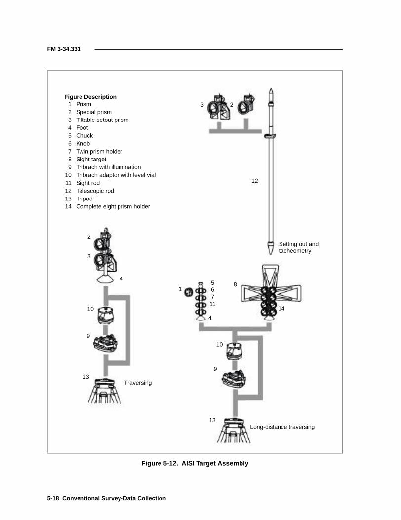
FM 3-34.331
Figure 5-12. AISI Target Assembly
Figure Description1 Prism2 Special prism3 Tiltable setout prism4 Foot5 Chuck6 Knob7 Twin prism holder8 Sight target9 Tribrach with illumination
10 Tribrach adaptor with level vial11 Sight rod12 Telescopic rod13 Tripod14 Complete eight prism holder
3 2
12
2
3
10
9
13
13
10
9
4
4
1
11
567
8
14
Setting out andtacheometry
Long-distance traversing
Traversing
5-18 Conventional Survey-Data Collection
FM 3-34.331
Tripod Target
5-34. The tripod target is the most stable, simplistic in construction, durable,and accurate. It ranges from a simple range pole to a tripod assembly that canbe permanently embedded in concrete. All targets are susceptible to theeffects of wind and precipitation. The tripod must be guyed or sand baggedand plumbed, and its legs should be securely set-in to prevent lateralmovement. On uneven ground, one leg may have to be shortened or dug in tomaintain a symmetrical appearance from all directions.
Range-Pole Targets
5-35. A range-pole target is used when the station does not require preciseaccuracy. The range pole is used to collect site-plan data quickly and involume.
TARGET SETUP
5-36. Observers sometimes have a difficult and tedious task locating targets.Depending on the type of terrain and foliage in the area and in wooded areaswhere the targets are not profiled or silhouetted, they are very difficult tolocate without direct sunlight shining on them. To expedite the locating oftargets, it is sometimes necessary to illuminate the target area. Generallyaccepted procedures are as follows:
• Use of a handheld flashing mirror.• Use of a strobe light or a portable light.• Use of vehicle headlights.
5-37. Once a target area is located, it becomes a simple task to find the exactlocation of the target. The use of iridescent cloth on the target in place ofregular signal cloth is recommended if the cloth can be interchanged.
5-38. In traverse operations where continual backsights and foresights areneeded and where distances are not excessive, target sets can be used in aleapfrog technique. The actual distance a target can be seen depends on thebackground, the lighting, and the weather. Care must be taken when pointinga target at the observer so that the view is not distorted through the telescope.A disadvantage of a target set is that only one at a time may be set at astation. When setting a target, it must be plumbed exactly over a station. Atarget is said to be plumb when it is centered to within 2 millimeters of thepoint.
LIGHTED TARGET SETS
5-39. A target set is a precise-survey lighting device used for short traverselines (about 4 kilometers or less). When a target set is used for nightobservations, it requires the attachment of an accessory lighting unit to theback of the target. The lighting unit consists of a metal hood with a light bulbmounted in the center. On the older target sets, the hood hangs on two smallmetal studs mounted at the top rear of the target. On the newer target sets,the hood slides down over the sides of the target from the rear.
Conventional Survey-Data Collection 5-19

FM 3-34.331
TARGET AND TRIBRACH ADJUSTMENT
PLATE BUBBLE
5-40. After the plate bubble has been centered, its position is checked byrotating the target (or instrument) through 180°. If the bubble does notremain centered, bring it halfway back using the foot screws to properly set it.For example, if the bubble position is off the center by four division marks,turn the foot screws to center the bubble until it is only off by two divisionmarks. The bubble should remain in this position while the target is rotated.The target is now level and can be used, but the error should be removed byadjusting the bubble tube.
5-41. The bubble can now be adjusted by turning the capstan screws at theend of the bubble tube until the bubble is centered. Repeat the levelingprocedure until the bubble remains in the center of the tube. Adjustmentsshould be done in small increments, no more than half the error should beadjusted out at one time. At the end of the procedure, make sure the capstanscrews are tightly secured.
CIRCULAR BUBBLE
5-42. Tribrachs use a circular level for rough and plate-fine leveling. After theplate bubble has been adjusted, the circular bubble can be adjusted (centered)by turning one or more of the adjustment screws located around the circular-bubble assembly.
OPTICAL PLUMMET
5-43. The optical axis of the plummet is aligned with the vertical axis of thetarget (or instrument) if the crosshairs of the optical plummet staysuperimposed on the center of the mark when the tribrach is revolved through180°. If the crosshairs do not stay superimposed, the plummet can be adjustedusing the following steps:
Step 1. Level the tribrach and put the crosshair over the mark and mark apoint.Step 2. Rotate the tribrach 120° and mark a second point.Step 3. Rotate the tribrach a second 120° and mark a third point.Step 4. Join the three points into a triangle.Step 5. Draw a bisecting line from the center of the sides of the triangle toform the center of the triangle (Figure 5-13[A]).Step 6. Adjust the optical plummet to the center of the triangle by looseningone side of the capstan screws and tightening the opposite screw(Figure 5-13[B]).Step 7. Repeat the process to verify the adjustment.Step 8. Ensure that all screws are snug after the adjustment is completedand that as little stress as possible is exerted on the capstan screws during theprocess.
5-20 Conventional Survey-Data Collection

FM 3-34.331
SIGNALS
5-44. Signals are survey targets that are either illuminated by natural sunlightor are electrically lighted by using batteries. The observations for all second-order, Class I triangulation and traverse are usually done at night by using signallights because of more stable atmospheric conditions, which allow for betterpointings. Observations may be made during daylight hours if the work situationprevents nighttime observations. The most commonly used signal light has a 5-inch reflector. This signal light is used for lines of sight in excess of 8 kilometers.Do not use the 5-inch light on lines of sight shorter than 8 kilometers. A rule ofthumb to follow for other light sizes is to add no more than 1-inch to thediameter of the light size for each mile observed.
POINTING
5-45. The exact horizontal and vertical pointing of the light is very important.If the light is not pointed exactly toward the instrument, only a portion of thereflector will be observed. In some cases, this portion will not be plumbed overthe station mark. The instrument operator must check the pointing beforestarting the observations by viewing the light through the telescope. Duringhazy weather and especially on long lines of sight, the view through thetelescope may appear as a bright spot surrounded by a flare. The instrumentoperator should request that the light keeper adjust the light slightly in ahorizontal and vertical arc while it is being viewed through the telescope untilthe best pointing can be determined. The best pointing is when the light is thebrightest. The light is then stopped and locked into position. If the lights are
Figure 5-13. Optical-Plummet Adjustment
A B
240°
120°
Bisect each side ofthe triangle.
Adjust optical plummet tothe center of the triangle.
Conventional Survey-Data Collection 5-21

FM 3-34.331
stacked, the bottom light must be pointed first. It can be adjusted forbrightness by adding or removing batteries. The light should never beimproperly pointed to reduce its brilliance (this will create an eccentric light).The lighting attachment must be pointed directly at the observer to eliminatethe appearance of uneven lighting of the target’s triangles.
MASKING
5-46. A light can be masked to reduce the size and brilliance of the beam bycovering equal portions of the lens (both above and below and to the right andleft of the center of the glass face). Opposite sides of the glass must be maskedequally to eliminate eccentricity. This type of masking is very good fordistances between 6 and 10 kilometers on normal nights. A sheet of orangescribe paper is required, but any other color will work almost as well. Whenusing the orange paper as a masking material, the light will present anorange glow with a brilliant white cross for the observer to pointing on. Atmaximum ranges, the orange glow is practically invisible through thetelescope, and at minimum ranges, the glow will help in identification of thelight.
FOCUSING
5-47. The light is focused by turning a screw at the rear of the bulb socket. Byturning this screw, the position of the bulb is changed in relationship to thereflector. If the light is not properly focused, it will appear as a fuzzy ball inthe telescope. The light may be focused by shining it on a flat surface about50 meters away and adjusting the size of the beam until it is slightly largerthan the light reflector. When no distant object is available, a field-expedientprocedure is to hold one’s hand about 6 inches in front of the light and adjustthe light until a dark spot the size of a quarter appears in the center of thebeam.
BRILLIANCE
5-48. The type of light bulb and the amount of voltage being used willdetermine the brilliance of the light. The light is issued with two differentbulbs: a standard 3.7- and a 6-volt bulb. The amount of voltage needed willvary depending on the lighting requirements. Various battery arrangementsare shown in Figure 5-14. If dry-cell batteries are not available or are tooweak, a field-expedient procedure is to connect two lights (with 6-volt bulbs) ina series and then connect them to a 12-volt wet-cell battery. Never apply morevoltage to a bulb than its rated value.
STACKING
5-49. When lights are needed from the same station to several observers, thesignal lights are stacked, generally on a range-pole tripod (Figure 5-15). Iflights are stacked over a station, they must be leveled and plumbed over thatstation mark. The lowest light must be leveled and plumbed first, then theother lights should be attached and individually leveled. Care must be takennot to knock the other lights out of plumb when attaching additional lights tothe pole.
5-22 Conventional Survey-Data Collection

FM 3-34.331
Figure 5-14. Battery Wiring Diagram
Figure 5-15. Stacking of 5-Inch Signal Lights
1. Cells connected in series. Output 9 volts, 24 amperes.
2. Cells connected in parallel. Output 1½ volts, 144 amperes.
3. Cells connected in series/parallel.Output 3 volts, 72 amperes.
4. Cells connected in series/parallel.Output 4½ volts, 72 amperes.
Outputs are based on theassumption of dry cells withan average of 1½ volts and24 amperes each.
To lamps
To lamps
To lamps
To lamps
Conventional Survey-Data Collection 5-23

FM 3-34.331
RANGING
5-50. When observations are made from a small (low) instrument stand, it issometimes impossible to plumb the lights directly over the station mark. Ifthis occurs, it is acceptable to use the lights on a range. The lights must bealigned on a range to all stations with a theodolite. The standard theodolitetripod or range-pole tripod is used as a stand and should be from 4 to30 meters from the station. Care must be taken to avoid introduction ofeccentricities.
NOTE: A target set is used as a signal in the same way as when it is used as a target.
EXPEDIENT LIGHTING
5-51. In the absence of a lighted target, a reflector may be used. By pointing apowerful, hand-held lantern flashlight at the reflector, a precise reflection willbe returned. There are many other types of expedient lights or signals thatcan be used when standard equipment is not available or is inoperative. Theseinclude such things as the headlight of a vehicle, a masked lantern, a boxedlightbulb, or chemical illumination lights. The survey-party chief must useexperience gained in the field and ingenuity to determine the properexpedient for a particular condition or problem.
5-52. The AISI is an electronic theodolite used to measure horizontal andvertical angles and distances. It represents these measurements on a displaypanel and can concurrently transfer them to a portable data-recording unit(DRU). The DRU can then transfer the data to an external microprocessor forprinting, plotting, and further refinement by surveying software.
DESCRIPTION
5-53. The AISI has two modes—a construction-survey mode with a range of2 kilometers and a topographic-survey mode with a range of 7 kilometers. TheAISI mounts on standard military tripods and consists of the followingmodular subassemblies:
• An electronic theodolite (a digital, automatic angle- and distance-reading/recording instrument with an electronic display/controlpanel).
• A DRU (an external memory device for storing data from thetheodolite).
5-54. The AISI interfaces with microprocessors, printers, and plotters. Ittransfers digital data directly from its DRU (via a cable interface) to themicroprocessor. The data is then refined by a fully integrated, 3D, ground-modeling, drafting-design system. The data can also be manually input to anyCAD software program.
5-55. The AISI measures distances from 2 meters to 7 kilometers with adigital readout of 1 millimeter and is accurate to ±2 millimeters + 3 ppm overthe measured distance. The horizontal and vertical angles are measured to an
SECTION III - AISI
5-24 Conventional Survey-Data Collection

FM 3-34.331
accuracy of 1″ of arc. The AISI has an electronic leveling device called a dual-axis compensator and adjusts for horizontal and vertical leveling with errorsof 6″ or less. The system has built-in communications with a range of 1 mile,an illuminated reticle for night operations, a 60-kilobyte memory capacity,and an alphanumeric keyboard and is powered by two dual-voltage,rechargeable, 12-volt nicad battery packs.
COMPONENTS
5-56. A detailed list of components for the AISI is described in TM 5-6675-332-10. The basic components for the AISI are shown in Figure 5-16, page5-26. They are as follows:
• A transport case.• A tribrach with an optical plummet, a battery pack, and a tribrach
battery cable.• A lens and an eyepiece cover.• A DRU and a DRU/AISI/battery cable.• Internal and external nicad batteries.• A battery charger and a charging converter.
LEVELING
5-57. The AISI uses a leveling device called a dual-axis compensator. It is anelectronic device that senses the pull of gravity and uses two imaginary planes(one parallel to the instrument’s face and the other perpendicular to thatplane) at the base of the instrument for determining the level. The displaysimulates an actual bubble level, and foot screws are used to adjust thedisplay bubble. The instrument then adjusts the horizontal and vertical axisto compensate for the instrument not being level. The working range of thecompensator is 6′. That means that the instrument can be up to 6′ off of leveland still adjust the horizontal and vertical axis. The sensitivity of the display-bubble graduations is 6″ in the fine-level mode and 20″ in the coarse-levelmode.
QUICK CHECK
5-58. A quick check is used to see if the AISI needs to be run through acollimation test. This procedure should be done at least once a day and alsoevery time the instrument operator changes. Any time the quick check fails,the AISI should be calibrated. This check compares the sightings at a pointtarget in the reverse and the direct modes. Pressing the angle-measure (A/M)key for each sighting will show the difference in the horizontal aim (dH) andthe difference in the vertical aim (dV) on the screen. Failure is determinedwhen the check of the dH and the dV is more than 5″ for horizontal and morethan 10″ for vertical from the mean. The collimation test will produce a valueto correct the angles (Figure 5-17, page 5-27). The procedures for thecollimation test are described in TM 5-6675-332-10.
Conventional Survey-Data Collection 5-25

FM 3-34.331
Figure 5-16. AISI System Components
Transport Case
Latches
Tribrach batterycable
Lenscover
Eyepiececover
Cableplug
On-offswitch
Illuminationintensity control
Tribrach
Plug forbattery box
Foot screwLocking
lever
Foot screw
Foot screw
Opticalplummet
DRU/AISI/battery cable
DRU
Internal Nicad Battery External Nicad Battery
Hook for tripod
Cable connection
Fuse
Charging time: 14 hours.Use time: 2-3 hours.
Charging time: 14 hours.Use time: 3-4 hours.
Connections forinternal battery
Plug to wall
Plugs to converter
Plug tocharger
Connection forexternal battery
Charging Converter Super Charger
BatteryBox
5-26 Conventional Survey-Data Collection

FM 3-34.331
DATA COLLECTION
5-59. The AISI has two ways of collecting data—the coordinate method andthe traverse method. In the coordinate method, all coordinates of points arecollected in the field and all computations are conducted internally in theAISI. In the traverse method, all data is stored in the AISI in the form of rawangles and distances. This data is then downloaded into a survey software tocompute coordinates. Surveyors determine which method to use. Table 5-2shows the pros and cons for each method.
COORDINATE METHOD
5-60. The coordinate method is used to collect coordinates for points thatrequire little or no use of a survey software. Before using this method, theuser-defined sequence (UDS) and coordinates for the starting control must beentered into the AISI. The result of this method is a visual display of
Figure 5-17. Quick-Check Example
Table 5-2. Two Methods of AISI Data Collection
Coordinate Method Traverse Method
Pros Cons Pros Cons
Can use without surveysoftware.
User needs to havestarting control.
Known coordinates do nothave to be known in the field.
User needs to know howto operate the surveysoftware.
Can label/stake points inthe field.
Coordinates cannot be readjusted.
Topographic points can bereadjusted.
No proof of whereor how coordinateswere derived.
Raw data is stored for proof ofhow the coordinates werederived.
Correction
Error
Direct reading
Reverse reading
Conventional Survey-Data Collection 5-27

FM 3-34.331
northings, eastings, and elevations. The angles are collected in Face I only.These points are also stored in a job file and can be converted to a points filewith the use of survey software.
TRAVERSE METHOD
5-61. The traverse method is used to collect data that will be processed andadjusted by survey software. This method provides a digital copy of thecollection process. The angles are measured in Face I and Face II and errorscan be accounted for. The results can be compared to standards andspecifications. Before starting the UDS, the starting coordinates must beentered into the AISI.
DATA STORAGE
5-62. The AISI is equipped with internal memory and an external memorydevice or DRU for storage of raw data, point information, and calculatedcoordinate data. Memory units make it easier to check and identify the dataafter collection. Two types of data (survey measurements [job files] and knowncoordinates and elevations [area files]) are saved in the memory. These joband area files consist of separate expansive memories and can be updatedindividually at any time.
Job Files
5-63. Job files are given a numeric, alpha, or alphanumeric title to permitlater identification. All survey data is stored in a job file and includes thecalculated coordinate and elevation data. When complete, these files can betransferred to a PC.
Area Files
5-64. Area files can be manually input and then stored or transferred from aPC. Several different files can be prepared in advance of the particular surveyjob. All known data can be stored for a project before departing to the job site.
FILE TRANSFER
5-65. The AISI can be connected to a PC or an external DRU. Information canbe transferred between either peripheral via a built-in serial interface. Theinstrument is connected to the DRU by a DRU/AISI/battery cable. Theconnection from the instrument to the PC is made with a standard 9-pin cable.Data transfer through the serial port requires that the standard parametersor protocol be set. When job and area files are transferred, they are copied butnot erased. The original file remains in the device and serves as a backup forthe project. Files can be deleted manually from the instrument or from the PC.Deleting files should only be done after the project is completed and properlyarchived.
FILE EDITING
5-66. The edit module allows viewing and editing of data within the recordingdevice and the external DRU or directly from the keyboard of the instrument.
5-28 Conventional Survey-Data Collection

FM 3-34.331
Edit functions include search, delete, insert, and change. The editing featuresare menu driven with the command options displayed on a screen. Options areselected using the keyboard. In the editing module, errors such as HT andstation number can be checked and changed by the instrument operator in thefield to ensure correctness before leaving the site.
COMMUNICATIONS
5-67. The AISI contains an internal communication system that enablesspeech communication to be carried out from the instrument to the receiverprism. This system is a one-way communication from the instrument to thereflector prism. There is a small microphone on the instrument panel that isactivated from the control panel. When activated, the measuring beam is usedentirely for speech transmission. This provides a communication channelwithout interference and without the need for a special radio-frequencypermit. This type of communication relies on good planning between theinstrument operator and the rodman to gather the appropriate data withouterrors or the need to revisit the area to fill in gaps in the collection process.The maximum range that this system is considered to function well is1,600 meters in good weather.
INSTRUMENT MAINTENANCE
5-68. The AISI is designed to withstand normal electromagnetic disturbancefrom the environment. However, it contains circuits that are sensitive to staticelectricity. Only the manufacturer is authorized to open the cover. To do so byanyone else will void the warranty. The AISI is designed and tested towithstand field conditions, but like other precision instruments, it requirescare and maintenance. Avoid rough jolts and careless treatment.
CLEANING
5-69. Keep the lenses and reflectors clean. Always use lens paper or othermaterial intended for cleaning optics (antistatic lens paper, a cotton wad, or alens brush). Caution must be exercised when the instrument is cleaned,especially when removing sand and dust from the lenses and the reflectors.Never use a coarse or dirty cloth or hard paper.
CONDENSATION
5-70. After surveying in moist weather, the instrument should be takenindoors. The instrument should be removed from the transport case and left todry naturally. Allow condensation that has formed on the lens to evaporate.
TRANSPORTING
5-71. Keep the AISI protected and in an upright position when it is not beingused or is being transported. Never carry the instrument while it is mountedon a tripod, because this will damage the tribrach screws. The diode used tosend the measurement signal is sensitive to shock, especially when theinstrument is on its side. The instrument should always be transported in itscase with the case locked and in an upright position. For shipment, the senderand the receiver should be clearly marked on the transport case.
Conventional Survey-Data Collection 5-29

FM 3-34.331
BATTERIES
5-72. The AISI has two types of batteries—an internal, 1-ampere-hour (AH)battery and an external, 2-AH battery. Both are 12-volt, rechargeable nicadbatteries and take 14 hours to recharge. The 1-AH battery can be fast chargedin 2 hours and when fully charged, will supply power for 2 continuous hours.The 2-AH battery is attached to the tripod and connected via a special cable. Itcan supply power for an additional 4 continuous hours. The AISI can also beconnected to a 12-volt vehicle battery.
5-73. The batteries are charged with a 115-volt alternating current (AC)battery charger. Three batteries can charge simultaneously when the chargeris connected to a charging converter. The batteries are first discharged beforerecharging begins. Once charged, the system will switch to a trickle charge tomaintain capacity. The condition of the battery is better preserved by usingthe battery until the low-battery indicator or automatic cutoff function isactivated. If the battery cuts off during use, the instrument will retain theobservation or function being used for up to 2 hours while the battery is beingrecharged.
NOTE: The AISI has an internal clock battery. A warning will be displayed when thisbattery is low. If this battery goes dead, the instrument will require reprogramming.When the warning appears, make arrangements to send the AISI to the repair shop assoon as possible. The internal battery will need to be replaced about every two years.
5-74. CAD software is commonly available and can produce results from basicsurvey plots to finished map sheets. Such drafting tools offer surveyors moreaccuracy, efficiency, flexibility, and quality in the production of hard-copyplots. CAD software, which is available through an Armywide contract, isused in topographic and construction survey units.
TOTAL-STATION DATA COLLECTION AND INPUT
5-75. Survey data can be entered into a CAD program by a variety oftechniques. The most favorable means is through a digital data file producedby electronic survey equipment. Total stations, GPS-S receivers, and someelectronic levels are commonly capable of recording survey data on electronicdata collectors. Such logging of data greatly increases the efficiency andaccuracy of data collection and eliminates human error associated with field-note recording. These digital data files also eliminate the tedious and error-prone manual entry of data. Automatic data logging clearly offers a superiormethod for recording and processing survey angles, distances, or coordinates,but it does not eliminate the requirement for field notes. To establish completesurvey records, field personnel must always record survey conditions, theproject description, unplanned procedures, and any other pertinentinformation.
5-76. For total-station instruments, various software/hardware packages areavailable to collect and process survey data. The AISI and a CAD interfaceoffer a full set of hardware and software for logging survey data, performingpostprocessing and adjustments, and importing data into a PC workstation forfurther processing. CAD data-collection packages store the input of X, Y, and
SECTION IV - CAD INTERFACE
5-30 Conventional Survey-Data Collection

FM 3-34.331
Z coordinates in the American Standard Code for Information Interchange(ASCII) format with a descriptor or code to indicate the surveyed featurealong with alphanumeric description data. The data can then be managed intomore complex and sophisticated packages of information to produce mapproducts of great detail. The resulting product can then be plotted in hardcopy or transferred into a more common format.
PLOTTING
5-77. CAD systems offer extreme flexibility in data plotting. The sheet sizesare dependent on the plotter or printer. The missions commonly performed bytopographic surveyors require a standing floor-mounted plotter that is capableof plotting D- and E-size sheets. Ink-jet plotters can output the most desiredmedia, including paper and mylar. Plotters that use ink-jet technology arecommon, inexpensive, and easy to maintain. The quality of the plot is equal toor greater than that of professional, manually drafted plots. These devicesproduce objects of any shape, color, or size; eliminate the need for tediousmanual drafting by cartographic specialists; and provide topographicsurveyors a necessary self-sufficient capability.
Conventional Survey-Data Collection 5-31

Chapter 6
Traverse
Traversing is a form of a control survey that is used in a wide variety ofsurveys. Traverses are a series of established stations that are linkedtogether by the angle and distance between adjacent points. The anglesare measured by theodolites, and the distances are measured by anEDME. The AISI total station combines both of these functions. Detailedinformation pertaining to traverse design, data collection, and limitationsare discussed in the SSGCN. Appendix B summarizes the standards forcontrol surveys. Appendix C details the recommended procedures fortraverse computations.
STARTING CONTROL
6-1. The purpose of a traverse is to locate points relative to each other on acommon grid. Surveyors need certain elements of starting data, such as thecoordinates of a starting point and an azimuth to an azimuth mark. There areseveral ways to obtain the starting data, and surveyors should make an effortto use the best data available to begin a traverse. Survey-control data isavailable in the form of existing stations (with the station data published in atrig list) or new stations (established by local agencies who can provide thestation data).
OPEN TRAVERSE
6-2. An open traverse (Figure 6-1, page 6-2) originates at a starting station,proceeds to its destination, and ends at a station with an unknown relativeposition. The open traverse is the least desirable traverse type, because it doesnot provide the opportunity for checking the accuracy of the fieldwork. Allmeasurements must be carefully collected, and every procedure for checkingposition and direction must be used. Therefore, the planning of a traverseshould always provide for closure of the traverse.
CLOSED TRAVERSE
6-3. A closed traverse either begins and ends on the same point or begins andends at points with previously determined (and verified) coordinates. In bothcases, the angles can be closed and closure accuracy can be mathematicallydetermined.
TRAVERSE CLOSED ON A STARTING POINT
6-4. A traverse that starts at a given point, proceeds to its destination, andreturns to the starting point without crossing itself in the process is referred
Traverse 6-1

FM 3-34.331
to as a loop traverse (Figure 6-2). Surveyors use this type of traverse toprovide control if there is little existing control in the area and only therelative position of the points is required. While the loop traverse providessome check of the fieldwork and computations, it does not ensure the detectionof all the systematic errors that may occur in a survey.
TRAVERSE CLOSED ON A SECOND KNOWN POINT
6-5. A traverse that is closed on a second known point begins at a point ofknown coordinates, moves through the required point(s), and terminates at asecond point of known coordinates. Surveyors prefer this type of traversebecause it provides a check on the fieldwork, computations, and starting data.It also provides a basis for comparing data to determine the overall accuracyof the work.
FIELDWORK
6-6. In a traverse, three stations are considered to be of immediatesignificance. These stations are the rear, the occupied, and the forward. Therear station is the station that the surveyors who are performing the traversehave just moved from, or it is a point to which the azimuth is known. Theoccupied station is the station at which the party is located and over which theinstrument is set. The forward station is the immediate destination of theparty or the next station in succession.
HORIZONTAL ANGLES
6-7. Always measure horizontal angles at the occupied station by sighting theinstrument at the rear station and measuring the clockwise angles to theforward station. Make instrument observations to the clearest and mostdefined and repeatable point of the target that marks the rear and forwardstations. Measurements are repeated according to the required specifications.
Figure 6-1. Open Traverse
JULIO
90°10′53.6″
AIR FORCE
ARMY
MARINE NAVY
= control station= traverse station
LEGEND:
TILDON
189°31′15.2″155°07′57.8″
191°32′41.2″
6-2 Traverse

FM 3-34.331
DISTANCE
6-8. Use an EDME to measure the distance in a straight line between theoccupied and the forward stations. Measurements are repeated according tothe required specifications.
TRAVERSE STATIONS
6-9. Select sites for traverse stations as the traverse progresses. Locate thestations in such a way that at any one station both the rear and forwardstations are visible. The number of stations in a traverse should be kept to aminimum to reduce the accumulation of instrument errors and the amount ofcomputing required. Short traverse legs (sections) require the establishmentand use of a greater number of stations and may cause excessive errors in theazimuth. Small errors in centering the instrument, in station-markingequipment, and in instrument pointings are magnified and absorbed in theazimuth closure as errors in angle measurement.
STATION MARKERS
6-10. Station markers are usually 2- by 2-inch wooden stakes, 6 inches ormore in length. These stakes (hubs) are driven flush with the ground. Thecenter of the top of the hub is marked with a surveyor’s tack or an X todesignate the exact point of reference for angular and linear measurements.
Figure 6-2. Closed Traverse (Loop)
101°28′
Station B
Station D
Station A
Station E
Station C
118°34′
102°11′
104°42′
113°05′
68.42′
115.89′
121.69′
88.41′164.95′
N
Traverse 6-3

FM 3-34.331
6-11. To assist in recovering a station, surveyors drive a reference (witness)stake into the ground so that it slopes toward the station. Surveyors mustwrite the identification of the station on the reference stake or on a tag that isattached to the stake with a lumber crayon or a china-marking pencil. Signalcloth may also be tied to the reference stake to further assist in identifying orrecovering a station.
STATION SIGNALS
6-12. A signal must be erected over survey stations to provide a sighting pointfor the instrument operator. The survey target set (discussed in Chapter 5) isthe most commonly used signal.
TRAVERSE-PARTY ORGANIZATION
6-13. The number of personnel available to perform survey operationsdepends on the unit’s TOE. The organization of these people into a traverseparty and the duties assigned to each member will depend on the unit’s SOP.The organization and duties of a traverse party are based on the functionalrequirements of the traverse.
6-14. The party chief selects and marks the traverse-station locations andsupervises the work of the other party members. The party chief also assistsin the survey recon and planning.
6-15. The survey team consists of the following members:
• Instrument operator. The instrument operator measures thehorizontal angles and distances at each traverse station.
• Recorder. The recorder keeps the field notes in a field notebook andrecords the angles and distances measured by the instrument operatorand all other information pertaining to the survey.
• Rodman. The rodman assists the party chief in marking the traversestations, removes the target from the rear station when signaled bythe instrument operator, and moves the target forward to the nexttraverse station.
AZIMUTH COMPUTATIONS
6-16. The azimuth of a line is the horizontal angle (measured clockwise) froma base direction to the line in question. To compute a traverse, surveyorsdetermine the azimuth for each traverse leg. The azimuth for each succeedingleg is determined by adding the value of the measured angle at the occupiedstation to the value of the azimuth from the occupied station to the rearstation. On occupation of each successive station, the first step is to computethe back azimuth of the preceding leg (the azimuth from the occupied stationto the rear station).
AZIMUTH ADJUSTMENT
6-17. Determine the need for an adjustment before beginning final-coordinatecomputations. If the angular error of closure (AEC) falls within the computed
6-4 Traverse

FM 3-34.331
AE, the azimuths of the traverse may be adjusted. The allowable AEC isdetermined for third-order, Class I traverse by the following formula:
where—10″ = AE for a single stationN = the number of traverse segments
If the azimuth error does not fall within the AEC, reobserve the station anglesof the traverse in the field.
AZIMUTH CORRECTION
6-18. Before determining a correction, compute the actual azimuth error. Theazimuth error is obtained by subtracting the known closing azimuth from thecomputed closing azimuth. This difference provides the angular error with theappropriate sign. By reversing this sign, the azimuth correction (with theappropriate sign) is obtained.
6-19. A traverse adjustment is based on the assumption that errors haveaccumulated gradually and systematically throughout the traverse. Anazimuth correction is applied accordingly. The correction is distributedsystematically among the angles of the traverse.
6-20. After the angles are adjusted, compute the adjusted azimuth of each legby using the starting azimuth and the adjusted angles at each traversestation. Compute the adjusted azimuth throughout the entire traverse andcheck against the correct azimuth to the closing azimuth mark beforebeginning any further traverse computations.
AZIMUTH-BEARING ANGLE RELATIONSHIP
6-21. The trigonometric functions (such as sine [denoted by sin], cosine[denoted by cos], and tangent [denoted by tan]) of the azimuth and the bearingare numerically the same. Surveyors may use either the azimuth or thebearing to compute the traverse. The choice will depend on the computer andthe equipment available.
AZIMUTH AND BEARING
6-22. If a calculator with angular functions is available, the use of theazimuth is easier since it eliminates the need to compute the bearing. If thefunctions must be determined from tables, it is necessary to first compute thebearing angles since the tabulation of functions is normally published forangles of 0° to 90°. The bearing of a line is the acute angle (an angle less than90°) formed by the line in question and the north-south line through theoccupied point. The bearing illustrates the relationship between the azimuthof a line and its direction.
QUADRANTS
6-23. Bearing angles are computed from a given azimuth depending on thequadrant in which the azimuth lies. When the azimuth is in the first quadrant
AEC 10″ N=
Traverse 6-5
FM 3-34.331
(0° to 90°), the bearing is equal to the azimuth. When the azimuth is in thesecond quadrant (90° to 180°), the bearing is equal to 180° minus the azimuth.When the azimuth is in the third quadrant (180° to 270°), the bearing is equalto the azimuth minus 180°. When the azimuth is in the fourth quadrant (270°to 360°), the bearing is equal to 360° minus the azimuth. Since the numericalvalues of the bearings repeat in each quadrant, the bearings must be labeledto indicate which quadrant they are in. The label must indicate whether thebearing angle is measured from the north or south line and whether it is eastor west of that line. For example, a line with an azimuth of 341°12′30″ falls inthe fourth or northwest (NW) quadrant and its bearing is N 18°47′30″ W.
COORDINATE COMPUTATIONS
6-24. If the coordinate of a point and the azimuth and distance from thatpoint to a second point are known, the coordinate of the second point can becomputed. The azimuth and distance from Station A to Station B aredetermined by measuring the horizontal angle from the azimuth mark toStation B and the distance from Station A to Station B.
6-25. A grid is a rectangular system with the easting and the northing linesforming right angles at the point of intersection. The computation of thedifference in northing (dN) (side Y) and the difference in easting (dE) (side X)requires the computation of a right triangle. The distance from Station A toStation B is the hypotenuse of the triangle, and the bearing angle (azimuth) isthe known angle. The following formulas are used to compute dN and dE:
dN = cos azimuth x distance
dE = sin azimuth x distance
6-26. If the traverse leg falls in the first (northeast [NE]) quadrant, the valueof the easting increases as the line goes east and the value of the northingincreases as it goes north. The product of the dE and the dN are positive andare added to the easting and northing of Station A to obtain the coordinate ofStation B.
6-27. When using trigonometric calculators to compute a traverse, enter theazimuth angle, and the calculator will provide the correct sign of the functionand the dN and the dE. If the functions are taken from tables, the computerprovides the sign of the function based on the quadrant. Lines going northhave positive dNs; lines going south have negative dNs. Lines going east havepositive dEs; lines going west have negative dEs.
6-28. The following are examples of how to determine the dN and the dE:
• Given an azimuth from Station A to Station B of 70°15′15″ and adistance of 568.78 meters (this falls in the first [NE] quadrant),compute the dN and the dE.dN = cos 70°15′15″ x 568.78 = +0.337848 x 568.78 = +192.16 mdE = sin 70°15′15″ x 568.78 = +0.941200 x 568.78 = +535.34 m
• Given an azimuth from Station B to Station C of 161°12′30″ and adistance of 548.74 meters (this falls in the second [southeast] [SE]quadrant), compute the dN and the dE.
6-6 Traverse

FM 3-34.331
dN = cos 161°12′30″ x 548.74 = -0.946696 x 548.74 = -519.49 mdE = sin 161°12′30″ x 548.74 = +0.322128 x 548.74 = +176.76 m
• Given an azimuth from Station C to Station A of 294°40′45″ and adistance of 783.74 meters (this falls in the fourth [NW] quadrant),compute the dN and the dE.dN = cos 294°40′45″ x 783.74 = +0.417537 x 783.74 = +327.24 mdE = sin 294°40′45″ x 783.74 = -0.908660 x 783.74 = -712.15 m
ACCURACY AND SPECIFICATIONS
6-29. The overall accuracy of a traverse depends on the equipment, theprocedures used in the measurements, the accuracy achieved, and theaccuracy of the starting and closing data. An accuracy ratio or ratio of closure(RC) of 1:5,000 is the minimum accuracy sought in topographic surveying. Inobtaining horizontal distances, an accuracy of at least 2 millimeters per100 meters must be obtained. When using a 1″ theodolite, turn the horizontalangles four positions. Keep an angular closure of 10″ per station.
SEA-LEVEL COEFFICIENT
6-30. The corrected field distances must be reduced to sea level. Along anytraverse with variations in elevation not exceeding 300 meters, sufficientaccuracy may be obtained by computing a sea-level coefficient (SLC) for theentire traverse.
LINEAR ERROR
6-31. To determine the acceptability of a traverse, compute the linear error ofclosure (LEC) (using the Pythagorean theorem), the AE, and the accuracyratio. The first step in a closed-traverse case is to determine the linear error inthe dN and the dE. In the case of a loop traverse, the algebraic sum of the dNsand the dEs should equal zero. Any discrepancy is the linear error in the dN orthe dE.
AE
6-32. The AE should then be computed using the appropriate accuracy ratio(1:5,000 or better) and the total length of the traverse. Compare this to theLEC. If the AE is greater than the LEC, the traverse is good and can beadjusted. If the traverse is not good, it must be redone.
RC
6-33. The RC determines the traverse accuracy and compares it to establishedstandards. The RC is the ratio of the LEC (after it is reduced to a commonratio and rounded down) to the total length of the traverse. If the RC does notfall within allowable limits, the traverse must be redone. It is very possiblethat the measured distances are correct and that the error can be attributed tolarge, compensating angular errors.
6-34. The accuracy of a traverse is the ratio of error to the total length of thetraverse. The RC must meet the specifications for the order of work beingperformed. Third-order, Class I accuracy requires an RC of 1:10,000. Accuracy
Traverse 6-7

FM 3-34.331
requirements are identified in DMS ST 031. If the traverse does not meet thisspecification, no further computations are necessary.
COORDINATE ADJUSTMENT
6-35. Make the adjustment of the traverse using the compass rule. This rulestates that for any leg of the traverse, the correction to be given to the dN orthe dE is to the total correction for the dN or the dE as the length of the leg isto the total length of the traverse. The total correction for the dN or the dE isnumerically equal to the error in northing (En) or the error in easting (Ee),but with the opposite sign.
6-36. When adjusting a traverse that starts and ends on two differentstations, compute the coordinates before the error is determined. Thecorrection (per leg) is determined in the same manner, but it is applieddirectly to the coordinates. The correction to be applied after computing thefirst leg is equal to the correction computed for the first leg. The correction tobe applied after computing the second leg is equal to the correction computedfor the first leg plus the correction computed for the second leg. The correctionfor the third leg equals the correction computed for the first leg plus thecorrection computed for the second leg plus the correction computed for thethird leg and so on throughout the traverse. The final correction must be equalto the total correction required.
6-8 Traverse

Chapter 7
Differential Leveling
Differential leveling is a technique used to determine differences inelevation between points that are remote from each other. Differentialleveling requires the use of a surveyor’s level together with graduatedmeasuring rods. An elevation is a vertical distance above or below areferenced datum. In surveying, the referenced datum is typically theMSL.
7-1. Some of the basic components for leveling are a level, a tripod, rods, andaccessories. A level has three major components—a telescope, a level tube,and a leveling head. There are three types of levels used in differentialleveling—automatic, digital, and optical-micrometer.
AUTOMATIC LEVELS
7-2. An automatic level uses a gravity-referenced prism or a compensator toorient the line of sight automatically. The instrument can be quickly leveledwhen a circular bubble level is used. When the bubble is centered, thecompensator takes over and maintains a horizontal line of sight. Automaticlevels are quick to set up and easy to use and can obtain second-order, Class IIprecision. The use of an automatic level entails using a freely moving prismthat is suspended by a fulcrum or wire as a compensator. The compensator issensitive to shock and must be kept nearly upright at all times. If the fulcrumor wire breaks, the instrument becomes useless. Gently tapping theinstrument, while viewing through the telescope, will cause the line of sight toveer slightly. This verifies that the compensator is working properly.
DIGITAL LEVELS
7-3. The level has been advanced, along with other survey equipment, intousing electronic measurements. The digital level uses electronic imageprocessing to determine heights and distances and to automatically recorddata for future transfer to a PC. The digital level is an automatic level that iscapable of normal optical measurements. When used in the electronic mode,together with a rod face that is graduated with a bar code, the instrumentcaptures and processes the image of the bar code. The processed image of thebar code is compared to the image of the entire rod and is programmed in thememory of the instrument. The difference in height and distance is thendetermined. The digital level contains predetermined programs for running
SECTION I - INSTRUMENTS AND EQUIPMENT
Differential Leveling 7-1

FM 3-34.331
any type of line or making adjustments to a sighting. The programs store,compute, and transfer the data in a manner similar to that of a total station.
OPTICAL-MICROMETER LEVELS
7-4. Optical-micrometer levels are similar to automatic levels in design. Theoptical-micrometer level can be purchased as an individual piece of equipmentor as an attachment for some automatic levels. Optical-micrometerattachments employ a plane parallel-plate lens, which when rotated willvertically deflect the line of sight of the incoming light ray. The optical-micrometer level subdivides the smallest graduation of the level rod to anaccuracy of about ±0.02 of the level-rod graduation, which means a recordeddirect reading of 0.001 meter. FGCC standards require an optical micrometerbe used for all first-order leveling. Some, but not all, digital levels are capableof meeting the required accuracy. Field operations for optical-micrometerleveling are nearly the same as for three-wire leveling except that optical-micrometer leveling uses double-scale invar rods and shorter sight distances.
LEVELING RODS AND ACCESSORIES
7-5. Leveling rods are manufactured of metal, wood, or fiberglass. They aregraduated in feet or meters and can be read directly to the nearest tenth of afoot or centimeter (Figure 7-1). To obtain a more precise reading, the readingis either estimated (single or three-wire method) or read with an opticalmicrometer or a digital image. Precision leveling requires one-piece rods thatare calibrated for accuracy and thermal expansion. For less precise work, anextendable or folding rod may be used. The sole of the rods are made of ametal base, machined for accuracy. Precise rods have a built-in circularbubble level to maintain the plumb of the rod. Placing the rod on a stable,consistent surface and maintaining plumb are keys to completing accurate,differential-leveling measurements.
7-6. The sole of the rod is placed on the BM or a temporary turning point. Theturning point can be any hardened surface with a definable and reproduciblehigh point. Manufactured points (for example, the marlinspike and the baseplate or turtle) can be used. The marlinspike is a stainless-steel pin that isdriven into soft surfaces at an angle and a depth sufficient to support the levelrod. The portable base plate is made of cast iron with a machined-steel pointto place the rod on. The base plate weighs 2.5 kilograms or more, can be usedon any surface, is more stable than the marlinspike, and is a requirement forhigher-order vertical surveys.
7-7. There are two types of tripods available for leveling—the fixed-leg andthe extension-leg. Either tripod is acceptable for second- and third-orderleveling. Generally, fixed-leg tripods are preferred, but conditions andlogistics may dictate using extension-leg tripods.
INSTRUMENT TESTING AND ADJUSTMENT
7-8. A collimation test for leveling (C-check) is a field determination of ageodetic level’s collimation error (C-factor). If the instrument is placedprecisely between two rods, the error is the same for the rear and forward
7-2 Differential Leveling

FM 3-34.331
Figure 7-1. Traditional Rectangular Cross-Section Leveling Rods Showing a Variety ofGraduation Markings
Level-rod faces
Met
erdi
giti
ndic
ator
0.5'
mar
k-
open
diam
ond
0.05
'M
inim
umgr
adua
tion
Foo
tmar
k-
solid
diam
ond
2m
eter
read
ing
1.85
met
erre
adin
g
No. 1Philadelphia;
feet, 10ths,100ths
No. 2Philadelphia;
meters,decimeters,centimeters
No. 3Direct
elevation;feet, 10ths,
100ths
No. 4Stadia;
feet, 10ths,1/2 10ths
No. 5Stadia;meters,
decimeters,centimeters
Differential Leveling 7-3
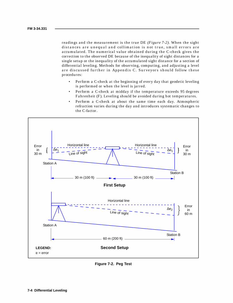
FM 3-34.331
readings and the measurement is the true DE (Figure 7-2). When the sightdistances are unequal and collimation is not true, small errors areaccumulated. The numerical value obtained during the C-check gives thecorrection to the observed DE because of the inequality of sight distances for asingle setup or the inequality of the accumulated sight distance for a section ofdifferential leveling. Methods for observing, computing, and adjusting a levelare discussed further in Appendix C. Surveyors should follow theseprocedures:
• Perform a C-check at the beginning of every day that geodetic levelingis performed or when the level is jarred.
• Perform a C-check at midday if the temperature exceeds 95 degreesFahrenheit (F). Leveling should be avoided during hot temperatures.
• Perform a C-check at about the same time each day. Atmosphericrefraction varies during the day and introduces systematic changes tothe C-factor.
Figure 7-2. Peg Test
ÿÿÿÿError
in30 m
30 m (100 ft) 30 m (100 ft)
60 m (200 ft)
Horizontal line
Horizontal lineHorizontal line
Line of sight Line of sight
Line of sight
First Setup
Second Setup
Errorin
30 m�� ��∆e1 ∆e1
Station A
Station B
Station A
Station B
Errorin
60 m�∆e2
LEGEND:e = error
7-4 Differential Leveling

FM 3-34.331
7-9. Differential-leveling observations are a repetitive operation, which due tothe regimen, often lead to a misunderstanding of the error sources. Due to thenumber of small systematic errors that are not discernible from geometricchecks, it is imperative to adhere to the prescribed procedures.
RECON
7-10. The leveling party performs a recon of the level line. Existing BMsshould be recovered and description/recovery notes prepared. BMs along thelevel line are established according to FGCC standards. At all orders ofaccuracy, the leveling party will verify that the starting BM elevation iscorrect by performing two-way leveling to the closest adjacent BM and back.These BMs should be part of the same level-line network that originallyestablished them. All members of the leveling party should exercise caution inthe choice of the route for leveling. High-traffic areas should be avoided, and ifthis is not possible, the leveling party should maintain high visibility at alltimes. Road-guard vests and additional personnel may be necessary to ensurethe leveling party’s safety. The ground over which the leveling progressesshould be free of characteristics that will introduce anomalous measurements.Ground that radiates high refraction or that is soft or uneven should bebypassed if possible. Any time that high scintillation is observed between thelevel and the rod, sight distances must be reduced.
DE DETERMINATION
7-11. The terms differential leveling, direct leveling, geodetic leveling, andspirit leveling all describe the same activity—the determination of DEs bydirect observation. These terms are used interchangeably in this publication.Follow these steps when performing third-order differential leveling:
Step 1. Determine the C-factor each day (just before leveling begins) andimmediately following any instance when the level is subjected to an unusualshock. Record the results of the C-check and keep them in the project records.Step 2. Start and end the leveling on BMs of third-order accuracy or higher.Step 3. Use three-wire-leveling methods.Step 4. Do not make observations closer to the ground than 0.5 meter. Do notmake observations on the rod higher than the project specifications require.Step 5. Leapfrog the rods forward.Step 6. Observe an even number of setups between the starting and endingBMs.Step 7. Place the rods in the red-rod-first sequence—rod number 1 or A of amatched pair of rods is marked (the foot of the rod is painted or a flagging isattached to the rod) to distinguish it from the other rod. The marked rod isobserved and the readings are recorded first for each setup.Step 8. Double-run the sections from the first BM out to the next BM andreturn.
SECTION II - PRECISE LEVELING PROCEDURES
Differential Leveling 7-5
FM 3-34.331
Step 9. Determine the maximum allowable disclosure. It will be the lesser ofthe following computed values:
• Twelve millimeters times the square root of the shorter-distance runbetween the BMs in kilometers.
• Twelve millimeters times the square root of the perimeter of the loop(front and back runs combined) in kilometers.
Step 10. Ensure that any action not specified above complies with thespecifications set forth by the FGCC.Step 11. Ensure compliance with steps 1 through 10 at all times unless thecustomer sets forth specific methodology, standards, or specifications forperforming the differential leveling in the request for survey support.
FIELD-PARTY COMPOSITION
7-12. The field party consists of four members—two rodmen, a level observer,and a recorder. The duties of each member are identified as follows:
• Rodmen. The rodmen hold the level rod; pace the sight distancesbetween the instrument and the level rod to ensure that the minimuminequalities of the setup and the accumulated sight distances aremaintained; hold the rod during readings in a plumb and steadyvertical position using the handles of the rod; place the rod in preciselythe same position for the backsight as it was for the foresight; carrythe rod using the handles (not over the shoulder); and ensure that therod face, the sole of the rod, and the circular bubble do not contact theground or receive a sudden shock (the level rod is a precise-surveyinstrument and must be treated as such).
• Observer. The observer performs the observations, is responsible forthe care and condition of the instrument and accessories, ensures thatthe maximum sight distance is not exceeded when moving the levelfrom the last foresight level rod to the next instrument setup, inspectsthe level tripod to ensure that all parts are secure and adjustedproperly, deliberately places the level to provide a stable platform,carefully levels the instrument and reads the appropriate data, andnever leaves the geodetic level unattended.
• Recorder. The recorder is responsible for all documentation duringthe survey; completes all note forms properly; ensures that allrequirements are satisfied; ensures that calculations and checks areperformed without errors and expeditiously and that all technicalspecifications have been satisfied; and prepares the description of BMsand any supplemental vertical-control points.
DATA RECORDING
7-13. Procedures for recording differential-leveling data are the same for allorders of accuracy. Differential-leveling data (include the names of the rodmen)is recorded on DA Form 5820 or any other single-sheet recording formauthorized by the party chief (Figure 7-3) . After recording the raw
7-6 Differential Leveling

FM 3-34.331
observations to three decimal places, use the following rules to determine themean center-wire reading to four decimal places:
• If the top interval is LARGER than the bottom, ADD the correctionfactor to the recorded center-wire reading to obtain the mean center-wire value to four decimal places.
• If the top interval is SMALLER than the bottom, SUBTRACT thecorrection factor from the recorded center-wire reading to obtain themean center-wire value to four decimal places.
7-14. The maximum permissible interval imbalance for third-orderspecification is 3 millimeters. Table 7-1, page 7-8, shows the correction factorsfor center-wire leveling.
Figure 7-3. Example of Survey Notes for Three-Wire Leveling
Sample
Differential Leveling 7-7

FM 3-34.331
C-FACTOR DETERMINATION
7-15. The determination of the C-factor may be performed as a part of levelingor separately. In all cases, the C-factor determination must be recordedseparately from other recordings and must comply with all requirements fornote keeping. It is desirable to determine the C-factor under the sameconditions that the leveling will be performed, including the sight distance,the slope of the ground, and the elevation of the line of sight above the ground.
7-16. Ensure that the circular bubble is carefully centered and that theobserved ends of the bubble in the level vial are in coincidence (whenapplicable) before reading the three wires. If the C-factor is determined duringthe first setup of the leveling, perform the following steps:
Step 1. Observe and record the foresight readings on the C-factor note sheetafter the regular foresight observations are recorded for the level line.Step 2. Position the rear rodman to about 10 meters behind the level.Step 3. Observe and record the rear-rod readings on the C-factor note sheet.Step 4. Move the level to about 10 meters behind the front rod.Step 5. Observe and record the front-rod readings on the C-factor note sheet.Step 6. Observe and record the rear-rod readings on the C-factor note sheet.
7-17. The total correction for curvature and refraction (C&R) must bedetermined for each far-rod reading using the distance from the instrument tothe far rod as the argument. Distances equal the product of the sum of theintervals (for a single set of three-wire readings) times the stadia-intervalfactor (SIF). The two corrections for C&R are algebraically added to the sum ofthe mean wire readings for the distant rod. The maximum permissibleC-factor varies with the SIF. Instruments with a SIF of 1:100 may not have aC-factor of greater than ±0.004. Instruments with a SIF of 1:200 may not havea C-factor of greater than ±0.007. Instruments with a SIF of 1:333 may nothave a C-factor of greater than ±0.010. If the C-factor is determined to begreater than what is permitted for the instrument’s SIF, the instrument mustbe adjusted and the C-factor redetermined before performing differentialleveling. The notes for the C-factor determination become part of theadministrative notes for the leveling operation.
Table 7-1. Correction Factors for Center-Wire Leveling
Difference in Intervals Center-Wire Correction Value
0.000 0.0000
0.001 0.0003
0.002 0.0007
0.003 0.0010
7-8 Differential Leveling

FM 3-34.331
CENTER-WIRE ADJUSTMENT
7-18. If the C-factor exceeds the SIF limits, a correction to the center wiremust be made. Determine this correction by multiplying the total rod intervalof the last foresight (distant rod) by the computed C-factor. Compute thecorrection to three places to the right of the decimal point and include thealgebraic sign of the C-factor. The correction to the center wire is algebraicallyadded to the last foresight mean wire reading. The result will be the correctedcenter-wire reading. Compute the corrected center-wire reading to threeplaces to the right of the decimal point.
7-19. Follow the manufacturer’s manual to adjust the level until the correctedcenter-wire reading is observed on the distant rod. Perform a C-check toensure that the new C-factor is within the acceptable limits.
SIF DETERMINATION
7-20. The SIF is required to compute the length (horizontal distance) from thestadia intervals and to determine the maximum AE for a level line. The SIFmust be determined if the reticle (which contains the etched stadia wires) isreplaced or changed. The notes from the SIF determination become part of therecords that are kept with the level and the project files.
7-21. The SIF determination is made by comparing the stadia intervals thatwere observed over a course of known distances. Lay out the course on areasonably level track, roadway, or sidewalk. Place nails or other marks in astraight line of measured distances of 25, 35, 45, 55, 65, and 75 meters. Plumbthe optical zero point of the level over the zero marker on the ground and levelthe instrument. The optical zero point of the level is found in themanufacturer’s manual. Read the rod at each of the six points and record theintervals. Compute the half-wire intervals as a check against erroneousreadings. Compute the sum of the six interval readings. The SIF is the sum ofthe measured distances (300 meters total), divided by the sum of the sixinterval readings.
7-22. To check for errors, compute the SIF for each of the six readings anddivide the measured distance by the total interval readings observed for thatdistance. The average of the six computations will serve as a numerical check.A tendency for the six computed values to creep in one direction indicates anerror in plumbing the optical zero point of the level over the zero point on theground.
Differential Leveling 7-9

Chapter 8
NAVSTAR GPS
This chapter provides a general overview of the NAVSTAR GPS. TheNAVSTAR GPS is a passive, satellite-based navigation system that isoperated and maintained by DOD. Its primary mission is to providepassive global positioning/navigation for air-, land-, and sea-basedstrategic and tactical forces.
8-1. A GPS receiver is a simple range-measurement device. Distances aremeasured between the receiver antenna and the satellites, and the position isdetermined from the intersections of the range vectors. These distances aredetermined by a GPS receiver, which precisely measures the time it takes asignal to travel from the satellite to the station. This measurement process issimilar to that used in conventional-pulsing marine-navigation systems andin phase-comparison EDM land-surveying equipment.
OPERATING AND TRACKING MODES
8-2. There are two, general operating modes from which GPS-derivedpositions can be obtained—absolute and relative (or differential) positioning.Within each of these two modes, range measurements to the satellites can beperformed by tracking either the phase of the satellite’s carrier signal or PRNcodes that are modulated on the carrier signal. In addition, GPS positioningcan be performed with the receiver operating in a static or dynamic(kinematic) environment. This variety of operational options results in a widerange of accuracy levels that can be obtained from the NAVSTAR GPS.Accuracies can range from 100 meters down to less than 1 centimeter.Increasing the accuracy to less than 1 centimeter requires additionalobservation time and can be achieved in real time. The selection of aparticular GPS operating and tracking mode (for example, absolute,differential, code, carrier, static, kinematic, or combinations thereof) dependson the user’s application. Topographic surveying typically requires differentialpositioning using carrier-phase tracking. Absolute modes are rarely used forgeodetic surveying except when worldwide reference control is beingestablished.
ABSOLUTE POSITIONING
8-3. Absolute positioning is the most common military and civil application ofNAVSTAR GPS for real-time navigation. When operating in this passive,
SECTION I - GPS OVERVIEW
NAVSTAR GPS 8-1

FM 3-34.331
real-time navigation mode, ranges to NAVSTAR GPS satellites are observedby a single receiver positioned on a point for which a position is desired. Thisreceiver may be positioned to be stationary over a point (static) or in motion(kinematic [such as on a vehicle, aircraft, missile, or backpack]). Two levels ofabsolute-positioning accuracy may be obtained—SPS and PPS. Withspecialized GPS receiving equipment, data-processing refinements, and long-term static observations, absolute-positional coordinates can be determined toaccuracy levels of less than 1 meter. These applications are usually limited toworldwide geodetic-reference surveys.
8-4. The SPS user is able to achieve real-time, 3D (point-positional) absolutepositioning. The SPS is the GPS signal that DOD authorizes to civil users.This level of accuracy is due to the deliberate degradation of the GPS signal byDOD for national security reasons. DOD degradation of the GPS signal isreferred to as selective availability (S/A). DOD has also implementedantispoofing (AS), which denies the SPS user the more accurate precision code(P-code).
8-5. Using the PPS requires DOD authorization for a decryption device that iscapable of deciphering the encrypted GPS signals. Army topographicsurveyors are authorized users; however, actual use of the equipment hassecurity implications. Real-time, 3D absolute-positional accuracies of 16 to 20meters are attainable through the PPS.
DIFFERENTIAL POSITIONING
8-6. Differential positioning is a process of measuring the differences incoordinates between two receiver points, each of which is simultaneouslyobserving/measuring satellite code ranges and/or carrier phases from theNAVSTAR GPS constellation. This process measures the difference in rangesbetween the satellites and two or more ground observing points. The rangemeasurement is performed by a phase-difference comparison, using either thecarrier or code phase. The basic principle is that the absolute-positioningerrors at the two receiver points will be about the same for a given instant.The resultant accuracy of these coordinate differences is at the meter level forcode-phase observations and at the centimeter level for carrier-phasetracking. These coordinate differences are usually expressed as 3D baselinevectors, which are comparable to conventional survey azimuth/distancemeasurements. DGPS positioning can be performed in the static or thekinematic mode.
SYSTEM CONFIGURATION
8-7. The NAVSTAR GPS consists of three distinct segments—the spacesegment (satellites), the control segment (tracking and monitoring stations),and the user segment (air-, land-, and sea-based receivers).
SPACE SEGMENT
8-8. The space segment consists of all GPS satellites in orbit. The firstgeneration of satellites were Block I or developmental. Several of thesesatellites are still operational. A full constellation of Block II or productionsatellites is now in orbit. The full constellation consists of 24 Block II
8-2 NAVSTAR GPS

FM 3-34.331
operational satellites (21 primary with 3 active on-orbit spares). There arefour satellites in each of six orbital planes inclined at 55° to the equator. Thesatellites are at altitudes of 10,898 nautical miles and have 11-hour,56-minute orbital periods. The three spares are transparent to the user on theground (the user is not able to tell which are operational satellites and whichare spares). A procurement action for Block IIR (replacement) satellites isunderway to ensure full system performance through the year 2025.
CONTROL SEGMENT
8-9. The control segment consists of five tracking stations that are locatedthroughout the world (Hawaii, Colorado, Ascension Island, Diego GarciaIsland, and Kwajalein Island). The information obtained from tracking thesatellites is used in controlling and predicting their orbits. Three of thestations (Ascension, Diego Gracia, and Kwajalein) are used for transmittinginformation back to the satellites. The master control station is located atColorado Springs, Colorado. All data from the tracking stations aretransmitted to the master control station where they are processed andanalyzed. Ephemerides, clock corrections, and other message data are thentransmitted back to the three stations that are responsible for subsequenttransmittal back to the satellites. The master control station is alsoresponsible for the daily management and control of the GPS satellites andthe overall control segment.
USER’S SEGMENT
8-10. The user’s segment represents the ground-based receiver units thatprocess the satellite signals and arrive at a user’s position. This segmentconsists of both military and civil activities for an unlimited number ofapplications in a variety of air-, land-, and sea-based platforms.
BROADCAST FREQUENCIES AND CODES
8-11. Each NAVSTAR satellite transmits signals on two L-band frequencies(designated as L1 and L2). The L1 carrier frequency is 1,575.42 megahertzand has a wavelength of about 19 centimeters. The L2 carrier frequency is1,227.60 megahertz and has a wavelength of about 24 centimeters. The L1signal is modulated with a P-code and a coarse-acquisition code (C/A-code).The L2 signal is modulated with a P-code only. Each satellite carries preciseatomic clocks to generate the timing information needed for precisepositioning. A navigation message is also transmitted on both frequencies.This message contains ephemerides, clock corrections and coefficients, thehealth and status of satellites, almanacs of all GPS satellites, and otherinformation.
PSEUDORANDOM NOISE
8-12. Modulated C/A- and P-codes are referred to as PRN codes. These PRNcodes are actually a sequence of very precise “time marks” that permit theground receivers to compare and compute the time of transmission between asatellite and a ground station. The range to the satellite can be derived fromthis transmission time. This is the basis behind GPS range measurements.
NAVSTAR GPS 8-3

FM 3-34.331
C/A-code pulse intervals are about every 300 meters in range. The moreaccurate P-code pulse intervals are about every 30 meters.
PSEUDORANGES
8-13. A pseudorange is the time delay between the satellite clock and thereceiver clock, as determined from C/A- or P-code pulses. This time differenceequates to the range measurement but is called a pseudorange since at thetime of the measurement, the receiver clock is not synchronized to thesatellite clock. In most cases, an absolute real-time, 3D navigational positioncan be obtained by observing at least four simultaneous pseudoranges.
SPS
8-14. The SPS uses the less precise C/A-code pseudoranges for real-time GPSnavigation. Due to deliberate DOD degradation of the C/A-code accuracy,100 meters in horizontal and 156 meters in vertical accuracy levels result.These accuracy levels are adequate for most civil applications where onlyapproximate real-time navigation is required.
PPS
8-15. The PPS is the fundamental military real-time navigational use of theGPS. Pseudoranges are obtained using the higher pulse rate (higher accuracy)P-code on both frequencies (L1 and L2). Real-time, 3D accuracies at the16-meter level can be achieved with the PPS. The P-code is encrypted toprevent unauthorized civil or foreign use. This encryption requires a specialdecryption code to obtain this 16-meter accuracy.
CARRIER-PHASE MEASUREMENTS
8-16. Carrier-frequency tracking measures the phase differences between theDoppler-shifted satellite and receiver frequencies. The phase differences arecontinuously changing due to the changing satellite earth-orbit geometry.However, such effects are resolved in the receiver and subsequent datapostprocessing. When carrier-phase measurements are observed andcompared between two stations (differential mode), 3D baseline-vectoraccuracy (below the centimeter level) between the stations is attainable. Newreceiver technology and processing techniques have allowed for carrier-phasemeasurements to be used in real-time centimeter positioning.
BROADCAST EPHEMERIS DATA
8-17. Each NAVSTAR GPS satellite periodically broadcasts data concerningclock corrections, system/satellite status and, most critically, its position orephemeris data. There are two basic types of ephemeris data—broadcast andprecise.
BROADCAST EPHEMERIDES
8-18. Broadcast ephemerides are predicted satellite positions that arebroadcast within the navigation message, which is transmitted from thesatellites in real time. The ephemerides can be acquired in real time by a
8-4 NAVSTAR GPS
FM 3-34.331
receiver that is capable of acquiring either the C/A- or P-code. The broadcastephemerides are computed by using the past tracking data of the satellites.The satellites are tracked continuously by the monitor stations to obtain morerecent data to use for orbit predictions. The data are analyzed by the mastercontrol station, and new parameters for the satellite orbits are transmittedback to the satellites. This upload is performed daily and the newly predictedorbital elements are transmitted every hour by the navigational message.Broadcast ephemerides are adequate to obtain needed accuracies for mostsurvey applications.
PRECISE EPHEMERIDES
8-19. Precise ephemerides are based on actual tracking data that arepostprocessed to obtain more accurate satellite positions. These ephemeridesare delayed for processing but are more accurate than the broadcastephemerides because they are based on actual tracking data and not predicteddata. Civilian users can obtain this information from the NGS or privatesources that maintain their own tracking networks and provide theinformation for a fee.
8-20. Absolute positioning involves the use of only one passive receiver at onestation location to collect data from multiple satellites to determine thestation’s location. It is not sufficiently accurate for precise surveying andpositioning uses. However, it is the most widely used GPS-positioning methodfor real-time navigation and location.
ABSOLUTE-POSITIONING ACCURACIES
8-21. Absolute-positioning accuracies are dependent on the user’sauthorization. The SPS user can obtain real-time, 3D accuracies of100 meters. The lower level of accuracies achievable using the SPS is due tothe intentional degradation of the GPS signal by DOD S/A. The PPS user(usually a DOD-approved user) can use a decryption device to achieve a 3Daccuracy in the range of 10 to 16 meters with a single-frequency receiver.Accuracy to less than 1 meter can be obtained from absolute GPSmeasurements when special equipment and postprocessing techniques areemployed.
8-22. By using broadcast ephemerides, the user is able to use pseudorangevalues in real time to determine absolute-point positions with an accuracy ofbetween 3 meters in the best of conditions and 80 meters in the worst ofconditions. By using postprocessed (precise) ephemerides, the user can expectabsolute point positions with an accuracy of near 1 meter in the best ofconditions and 40 meters in the worst of conditions.
PSEUDORANGING
8-23. When a GPS user performs a GPS navigational solution, only anapproximate range (or pseudorange) to selected satellites is measured. In
SECTION II - ABSOLUTE POSITIONING
NAVSTAR GPS 8-5

FM 3-34.331
order to determine the user's precise GPS location, the known range to thesatell ite and the position of those satell ites must be known. Bypseudoranging, the GPS user measures an approximate distance between theantenna and the satel l i te without any correct io ns fo r erro rs insynchronization between the clock of the transmitter and the clock of thereceiver. This measurement correlates by correlation of a satellite-transmitted code and a reference code that is created by the receiver. Thedistance the signal has traveled is equal to the velocity of the transmission ofthe satellite multiplied by the elapsed time of transmission. The satellite-signal velocity changes that are due to tropospheric and ionosphericconditions must be considered.
8-24. The accuracy of the positioned point is a function of the range-measurement accuracy and the geometry of the satellites (reduced tospherical intersections with the earth’s surface). A description of thegeometrical magnification of uncertainty in a GPS-determined point positionis the dilution of precision (DOP). Repeated and redundant range observationswill generally improve range accuracy. However, the DOP remains the same.In a static mode (the GPS antenna stays stationary), range measurements toeach satellite can be continuously remeasured over varying orbital locations ofthe satellite(s). The varying satellite orbits cause varying positionalintersection geometry. In addition, simultaneous range observations tonumerous satellites can be adjusted using weighting procedures that arebased on the elevation and the pseudorange-measurement reliability.
8-25. Four pseudorange observations are needed to resolve a GPS 3Dposition. Three pseudorange observations are needed for a two-dimensional(2D) (horizontal) location. There are often more than four pseudorangeobservations due to the need to resolve the clock biases contained in both thesatellite and the ground-based receiver. In computing the X, Y, and Zcoordinates of a point, a fourth unknown parameter (clock bias) must also beincluded in the solution.
ABSOLUTE-POSITIONING ERROR SOURCES
8-26. There are numerous sources of measurement errors that influence GPSperformance. The sum of all systematic errors or biases contributing to themeasurement error is referred to as a range bias. The observed GPS range(without removal of biases) is referred to as a biased range or pseudorange.Principal contributors to the final range error that also contribute to overallGPS error are ephemeris error, satellite-clock and electronics inaccuracies,tropospheric and ionospheric refraction, atmospheric absorption, receivernoise, and multipath effects. Other errors include those induced by DOD S/Aand AS. In addition to these major errors, the GPS also contains randomobservation errors (such as unexplainable and unpredictable time variation).These errors are impossible to model and correct. The following paragraphsdiscuss errors associated with absolute GPS-positioning modes. Many of theseerrors are either eliminated or significantly minimized when the GPS is usedin a differential mode, because the same errors are common to both receiversduring simultaneous observing sessions.
8-6 NAVSTAR GPS

FM 3-34.331
EPHEMERIS ERRORS AND ORBIT PERTURBATIONS
8-27. Satellite-ephemeris errors are errors in the prediction of a satellite'sposition, which may then be transmitted to the user in the satellite datamessage. Ephemeris errors are satellite dependent and are very difficult tocorrect completely and compensate for, because the forces acting on thepredicted orbit of a satellite are difficult to measure directly. The previouslystated accuracy levels are subject to the equipment’s condition andperformance. Ephemeris errors produce equal error shifts in the calculatedabsolute-point positions.
CLOCK STABILITY
8-28. The GPS relies very heavily on accurate time measurements. GPSsatellites carry rubidium and cesium time standards that are usually accurateto 1 part in 10 trillion and 1 part in 100 trillion, respectively, while mostreceiver clocks are actuated by a quartz standard accurate to 1 part in 100million. A time offset is the difference between the time as recorded by thesatellite clock and the time recorded by the receiver. A range error that isobserved by the user as a result of time offsets between the satellite andreceiver clock is a linear relationship and can be approximated.
8-29. Unpredictable transient situations that produce high-order departuresin clock time can be stored for short periods of time. In a plane survey,departure is defined as the difference between the castings of the two ends ofthe line, which may be either plus or minus. Predictable time drift of thesatellite clocks is closely monitored by ground-control stations. Through closemonitoring of the time drift, the ground-control stations are able to determinesecond-order polynomials that accurately model the time drift. These second-order polynomials, determined to model the time drift, are included in thebroadcast message in an effort to keep this drift to within 1 millisecond. Thetime synchronization between the GPS satellite clocks is kept to within20 nanoseconds through the broadcast-clock corrections as determined by theground-control stations and the synchronization of GPS standard time to theuniversal time, coordinated (UTC) to within 100 nanoseconds. Random timedrifts are unpredictable, thereby making them impossible to model.
8-30. GPS receiver-clock errors can be modeled in a manner similar to GPS-satellite-clock errors. In addition to modeling the satellite-clock errors and inan effort to remove them, an additional satellite should be observed duringoperation to solve for an extra clock offset parameter along with the requiredcoordinate parameters. This procedure is based on the assumption that theclock bias is independent at each measurement epoch. Rigorous estimation ofthe clock terms is more important for point positioning than for differentialpositioning. Many of the clock terms cancel each other when the positionequations are formed from observations during a differential-survey session.
IONOSPHERIC DELAYS
8-31. GPS signals are electromagnetic signals and as such are nonlinearlydispersed and refracted when transmitted through a highly chargedenvironment like the ionosphere. Dispersion and refraction of the GPS signalare referred to as ionospheric range effects, because dispersion and refraction
NAVSTAR GPS 8-7

FM 3-34.331
of the signal result in an error in the GPS range value. Ionospheric rangeeffects are frequency dependent.
8-32. The error effect of ionosphere refraction on GPS range values isdependent on sunspot activity, the time of day, and satellite geometry. GPSoperations conducted during periods of high sunspot activity or with satellitesnear the horizon produce range results with the most amount of ionosphericerror. GPS operations conducted during periods of low sunspot activity,during the night, or with a satellite near the zenith will produce range resultswith the least amount of ionospheric error.
8-33. Resolution of ionospheric refraction can be accomplished by using adual-frequency receiver (a receiver that can simultaneously record both L1and L2 frequency measurements). During a period of uninterruptedobservation of the L1 and L2 signals, these signals can be continuouslycounted and differenced. The resultant difference shows the variable effects ofthe ionosphere delay on the GPS signal. Single-frequency receivers used todetermine an absolute or differential position typically rely on ionosphericmodels that predict the effects of the ionosphere. Recent efforts have shownthat significant ionospheric-delay removal can be achieved using single-frequency receivers.
TROPOSPHERIC DELAYS
8-34. GPS signals in the L-band level are refracted and not dispersed by thetroposphere. Tropospheric conditions that cause refraction of the GPS signalcan be modeled by measuring the dry and wet components.
MULTIPATH EFFECTS
8-35. Multipath describes an error that affects positioning and occurs whenthe signal arrives at the receiver from more than one path. Multipathnormally occurs near large reflective surfaces, such as a building or structurewith a reflective surface, a chain-link fence, or antenna arrays. Multipath iscaused by the reflection of the GPS signal off of a nearby object, whichproduces a false signal at the GPS antenna. GPS signals received as a resultof multipath give inaccurate GPS positions when processed. Newer receiverand antenna designs and thorough mission planning can minimize multipatheffects as an error source. The averaging of GPS signals over a period of timecan also reduce multipath effects.
RECEIVER NOISE
8-36. Receiver noise includes a variety of errors associated with the ability ofthe GPS receiver to measure a finite time difference. These errors includesignal processing, clock/signal synchronization and correlation procedures,receiver resolution, and signal noise.
S/A AND AS
8-37. S/A purposely degrades the satellite signal to create position errors bydithering the satellite clock and offsetting the satellite orbits. The effects of S/Acan be eliminated by using differential techniques. AS is implemented byinterchanging the P-code with a classified, encrypted P-code called a Y-code.
8-8 NAVSTAR GPS

FM 3-34.331
This denies users who do not possess an authorized decryption device.Manufacturers of civil GPS equipment have developed techniques, such assquaring or cross correlation, to make use of the P-code when it is encrypted.
USER EQUIVALENT RANGE ERROR
8-38. The previously described error sources or biases are principalcontributors to the overall GPS range error. This total error budget is oftensummarized as the user equivalent range error (UERE). As mentionedpreviously, errors can be removed or at least effectively suppressed bydeveloping models of their functional relationships in terms of variousparameters that can be used as a corrective supplement for the basic GPSinformation. Differential techniques also eliminate many of these errors.Table 8-1 lists significant sources for errors and biases and correlates them tothe segment source.
ACCURACIES
8-39. The absolute value of range accuracies obtainable from the GPS arelargely dependent on which code (C/A or P) is used to determine positions.These range accuracies (for example, UERE), when coupled with thegeometrical relationships of the satellites during the position determination(for example, DOP), result in a 3D ellipsoid that depicts uncertainties in allthree coordinates. Given the changing satellite geometry and other factors,
Table 8-1. GPS Range-Measurement Accuracy
SegmentSource
Error Source
Absolute PositioningDifferentialPositioning(P-code) (m)
C/A-codePseudorange (m)
P-codePseudorange (m)
Space
Clock stability 3.0 3.0 Negligible
Orbitperturbations
1.0 1.0 Negligible
Other 0.5 0.5 Negligible
Control
Ephemerispredictions
4.2 4.2 Negligible
Other 0.9 0.9 Negligible
User
Ionosphere 3.5 2.3 Negligible
Troposphere 2.0 2.0 Negligible
Receiver noise 1.5 1.5 1.5
Multipath 1.2 1.2 1.2
Other 0.5 0.5 0.5
1σ UERE ±12.1 ±6.5 ±2.0
NAVSTAR GPS 8-9

FM 3-34.331
GPS accuracy is time/location dependent. Error propagation techniques areused to define nominal accuracy statistics for a GPS user.
DOP
8-40. The final positional accuracy of a point (determined by using absoluteGPS-S techniques) is directly related to the geometric strength of theconfiguration of satellites observed during the survey session. GPS errorsresulting from satellite-constellation geometry can be expressed in terms ofDOP. In mathematical terms, DOP is a scalar quantity used in an expressionof a ratio of the positioning accuracy. It is the ratio of the standard deviationof one coordinate to the measurement accuracy. DOP represents thegeometrical contribution of a certain scalar factor to the uncertainty (forexample, standard deviation) of a GPS measurement. DOP values are afunction of the diagonal elements of the covariance matrices of the adjustedparameters for the observed GPS signal. DOP values are used in pointformulations and determinations. DOP is a scalar quantity of the contributionof the configuration of satellite-constellation geometry to the GPS accuracy.DOP can also be a measure of the strength of the satellite-constellationgeometry. The more satellites that can be observed and used in the finalsolution, the better the solution. Since DOP can be used as a measure ofgeometrical strength, it can also be used to selectively choose four satellites ina particular constellation that will provide the best solution.
Geometric DOP
8-41. The main form of DOP used in absolute GPS positioning is thegeometric DOP (GDOP). GDOP is a measure of accuracy in a 3D position andtime. The final positional accuracy equals the actual range error multiplied bythe GDOP.
Positional DOP
8-42. Positional DOP (PDOP) is a measure of the accuracy in 3D position. ThePDOP values are generally developed from satellite ephemerides beforeconducting a survey. When developed before a survey, PDOP can be used todetermine the adequacy of a particular survey schedule. This is valid forrapid-static or kinematic surveys but is less valid for a long-duration staticsurvey.
8-43. PDOP represents position recovery at an instant in time and is notrepresentative of a whole session of time. A PDOP error is generally given inunits of meters of error per 1-meter error in a pseudorange measurement.When using pseudorange techniques, PDOP values in the range of 4 to 5meters of error per 1-meter error are considered very good, while PDOPvalues greater than 10 meters of error per 1-meter error are considered verypoor. For static surveys, it is generally desirable to obtain GPS observationsduring a time of rapidly changing GDOP or PDOP.
8-44. When the values of PDOP or GDOP are viewed over time, peak or highvalues (greater than 10 meters of error per 1-meter error) can be associatedwith satellites in a constellation of poor geometry. The higher the PDOP orGDOP, the poorer the solution for that instant in time. This is critical in
8-10 NAVSTAR GPS

FM 3-34.331
determining the acceptability of real-time navigation and photogrammetricsolutions. Poor geometry can be the result of satellites orbiting near eachother or being in the same plane or at similar elevations.
Horizontal DOP
8-45. Horizontal DOP (HDOP) is a measurement of the accuracy in a 2Dhorizontal position. The HDOP statistic is most important in evaluatingGPS-Ss intended for horizontal control. HDOP is the RMS error determinedfrom the final variance-covariance matrix divided by the standard error of therange measurements. HDOP roughly indicates the effects of satellite-rangegeometry on a resultant position.
Vertical DOP
8-46. Vertical DOP (VDOP) is a measurement of the accuracy in the standarddeviation of a vertical height. Table 8-2 indicates generally accepted DOPvalues for a baseline solution.
ACCURACY COMPARISONS
8-47. It is important that GPS-accuracy measures clearly identify the statisticfrom which they were derived. A 100-meter or positional variance-covariancematrix is meaningless unless it is identified as being either one dimensional(1D), 2D, or 3D, along with the applicable probability level. For example, aPPS 16-meter 3-deviation accuracy is, by definition, a spherical error probable(SEP) (50 percent). This 16-meter SEP equates to a 28-meter 3D, 95 percentconfidence spheroid. If transformed to 2D accuracy, the SEP equates roughlyto a 10-meter circular error probable (CEP), a 12-meter root-mean-square
Table 8-2. Acceptable DOP Values
Measurement DOP Value Comment
GDOP andPDOP
Less than 10 meters of error per 1-meter error (optimally 4 to 5 metersof error per 1-meter error)
In static GPS surveying, it is desirable to have aGDOP/PDOP that changes during the time of theGPS-S session.
The lower the GDOP/PDOP, the better theinstantaneous point-position solution.
HDOP andVDOP
2 meters of error per 1-meter errorThis DOP value results in the best constellation offour satellites.
NAVSTAR GPS 8-11
(RMS), a 2-meter 2-deviation RMS, or a 36-meter 3-deviation RMS. Table 8-3shows additional information on GPS-measurement statistics. In addition,absolute GPS point-positioning accuracies are defined relative to an earth-centered coordinate system/datum. This coordinate system will differsignificantly from local or construction datums. Nominal GPS accuracies mayalso be published as design or tolerance limits, and accuracies achieved candiffer significantly from these values.

FM 3-34.331
Table 8-3. Representative GPS Error-Measurement Statistics for Absolute-Point Positioning
Error-Measure StatisticProbability
%
RelativeDistance
(ft) 1
GPS Precise-Positioning Service
(m)2
GPS Standard-Positioning Service
(m)2
1D Measures σσσσN or σσσσE σσσσU σσσσN or σσσσE σσσσU
Probable error 50.00 0.6745 σ ±4.0 ±9.0 ±24.0 ±53.0
Average error 57.51 0.7979 σ ±5.0 ±11.0 ±28.0 ±62.0
1σσσσ standard error/deviation 3 68.27 1.0000 σ ±6.3 ±13.8 ±35.3 ±78.0
90% probability (map accuracy standard) 90.00 1.6450 σ ±10.0 ±23.0 ±58.0 ±128.0
95% probability/confidence 95.00 1.9600 σ ±12.0 ±27.0 ±69.0 ±153.0
2σ standard error/deviation 95.45 2.0000 σ ±12.6 ±27.7 ±70.7 ±156.0
99% probability/confidence 99.00 2.5760 σ ±16.0 ±36.0 ±91.0 ±201.0
3σ standard error (near certainty) 99.73 3.0000 σ ±19.0 ±42.0 ±106.0 ±234.0
2D Measures 4 Circular Radius Circular Radius
1σ standard error circle5 39.00 1.0000 σc 6.0 35.0
CEP6 50.00 1.1770 σc 7.0 42.0
1-deviation RMS (1DRMS) 3, 7 63.00 1.4140 σc 9.0 50.0
Circular map accuracy standard 90.00 2.1460 σc 13.0 76.0
95% 2D positional confidence circle 95.00 2.4470 σc 15.0 86.0
2-deviation RMS (2DRMS) 8 98.00 2.8300 σc 17.8 100.0
99% 2D positional confidence circle 99.00 3.0350 σc 19.0 107.0
3.5σ circular near-certainty error 99.78 3.5000 σc 22.0 123.0
3-deviation RMS (3DRMS) 99.90 4.2400 σc 27.0 150.0
3D Measures Spherical Radius Spherical Radius
1σ spherical standard error9 19.90 1.0000 σs 9.0 50.0
SEP10 50.00 1.5400 σs 13.5 76.2
Mean radial spherical error (MRSE)11 61.00 1.7300 σs 16.0 93.0
90% spherical accuracy standard 90.00 2.5000 σs 22.0 124.0
95% 3D confidence spheroid 95.00 2.7000 σs 24.0 134.0
99% 3D confidence spheroid 99.00 3.3700 σs 30.0 167.0
Spherical near-certainty error 99.89 4.0000 σs 35.0 198.0
8-12 NAVSTAR GPS

FM 3-34.331
ROOT-MEAN-SQUARE ERROR MEASURES
8-48. Two-dimensional GPS positional accuracies are normally estimatedusing a RMS radial-error statistic. A 1-sigma (sigma is denoted by σ) RMSerror equates to the radius of a circle with a 63 percent probability that theposition is within the circle. A circle of twice this radius (2σ) represents abouta 97 percent probability. This 97 percent probability circle, or 2σ RMS, is themost common positional-accuracy statistic used in GPS surveying. In someinstances, a 3σ RMS (99 or more percent probability) is used. This RMS errorstatistic is also related to the positional variance-covariance matrix. An RMSerror statistic represents the radius of a circle and, therefore, is not precededby a ± sign.
PROBABLE ERROR MEASURES
8-49. Three-dimensional GPS-accuracy measurements are commonlyexpressed by SEP. The SEP represents the radius of a sphere with a50 percent confidence or probability level. This spheroid radial measure onlyapproximates the actual 3D ellipsoid representing the uncertainties in the
Table 8-3. Representative GPS Error-Measurement Statistics for Absolute-Point Positioning(continued)
Error-Measure StatisticProbability
%
RelativeDistance
(ft) 1
GPS Precise-Positioning Service
(m)2
GPS Standard-Positioning Service
(m)2
1Valid for 2- and 3-deviation only if σσσσN = σσσσE = σσσσU. (σσσσminimum /σσσσmaximum ) generally must be ≥≥≥≥0.2. Relative distance usedunless otherwise indicated.2Representative accuracy based on 1990 Federal Radio Navigation Plan (FRNP) simulations for PPS and SPS (FRNPestimates shown in bold italics) and that σσσσN ≈ σσσσE. SPS may have significant short-term variations from these nominalvalues.3Statistic used to define USACE hydrographic survey depth and positioning criteria.4The 1990 FRNP also proposes SPS maintain, at minimum, a 2D confidence of 300 meters @ 99.99 percentprobability.5σσσσC 0.5 (σσσσN + σσσσE)—approximates standard error ellipse.6CEP 0.589 (σσσσN + σσσσE) ≈ 1.18 σσσσC.71DRMS (σσσσN
2 + σσσσE2)½.
82DRMS 2 (σσσσN2 + σσσσE
2)½.9σσσσS 0.333 (σσσσN + σσσσE + σσσσU).10SEP 0.513 (σσσσN + σσσσE + σσσσU).11MRSE (σσσσN
2 + σσσσE2 + σσσσU
2)½.
LEGEND:
σσσσc = approximate standard error ellipse
σσσσs = nominal standard error
NOTES:
1. Most commonly used statistics are shown in bold-face type.
2. Estimates are not applicable to differential GPS positioning. Circular/spherical error radii do not have ± signs.
3. Absolute positional accuracies are derived from GPS-simulated user range errors/deviations and the resultantgeocentric-coordinate solution (X-Y-Z) covariance matrix, as transformed to a local datum (N-E-U or ΦΦΦΦ-λλλλ-h). GPSaccuracy will vary with GDOP and other numerous factors at time(s) of observation. The 3D covariance matrix yieldsan error ellipsoid. Transformed ellipsoidal dimensions given (for example, σσσσN, σσσσE, or σσσσU) are only average valuesobserved under nominal GDOP conditions. Circular (2D) and spherical (3D) radial measures are only approximationsto this ellipsoid, as are probability estimates.
NAVSTAR GPS 8-13

FM 3-34.331
geocentric coordinate system. In 2D horizontal positioning, a CEP statistic iscommonly used, particularly in military targeting. The CEP represents theradius of a circle containing a 50 percent probability of position confidence.
8-50. Absolute positioning does not provide the accuracies needed for mostsurvey-control projects due to existing and induced errors. To eliminate theerrors and obtain higher accuracies, the GPS can be used in a differential-positioning mode. The terms “relative” and “differential” used throughout thismanual have similar meaning. Relative is used when discussing one thing inrelation to another. Differential is used when discussing the method ofpositioning one thing in relation to another. Differential positioning requiresthat at least two receivers be set up at two stations (usually one is known) tocollect satellite data simultaneously to determine coordinate differences. Thismethod positions the two stations relative to each other (hence the termrelative positioning) and can provide the accuracies required for basic landsurveying.
CODE-PSEUDORANGE TRACKING
8-51. Differential positioning (using code pseudoranges) is performedsimilarly to code-pseudorange tracking for absolute positioning. Code-pseudorange tracking effectively eliminates or minimizes some of the majoruncertainties. This pseudorange process results in the absolute coordinates ofthe user on the earth’s surface. Errors in range are directly reflected inresultant coordinate errors. Differential positioning is not as concerned withthe absolute position of the user as with the relative difference between twouser positions, which are simultaneously observing the same satellites. Sinceerrors in the satellite position and atmospheric-delay estimates are effectivelythe same at both receiving stations, the errors cancel each other to a largeextent.
8-52. For example, if the true pseudorange distance from a known controlpoint to a satellite is 100 meters and the observed or measured pseudorangedistance is 92 meters, then the pseudorange error or correction is 8 meters forthat particular satellite. A pseudorange correction (PRC) can be generated foreach satellite being observed. If a second receiver is observing at least four ofthe same satellites and is within a reasonable distance, it can use these PRCsto obtain a relative position to the known control point since the errors will besimilar. Thus, the relative distance (coordinate difference) between the twostations is reasonably accurate regardless of poor absolute coordinates. Ineffect, the GPS-observed baseline vectors are no different from azimuth/distance observations. As with a total station, any type of initial-coordinatereference can be input to start the survey.
8-53. The GPS coordinates will not coincide with the user’s local-projectdatum coordinates. Since differential-survey methods are concerned only withrelative coordinate differences, disparities with the global reference systemused by the NAVSTAR GPS are not significant for topographic purposes.Therefore, GPS coordinate differences can be applied to any type of local-project reference datum (for example, NAD 27 or NAD 83).
SECTION III - DIFFERENTIAL PRECISE POSITIONING
8-14 NAVSTAR GPS

FM 3-34.331
CARRIER-PHASE TRACKING
8-54. Differential positioning (using carrier phases) uses a formulation ofpseudoranges. The process becomes more complex when the carrier signalsare tracked so that range changes are measured by phase resolution. Incarrier-phase tracking, an ambiguity factor is added, which must be resolvedto obtain a derived range. Carrier-phase tracking provides for a more accuraterange resolution due to the short wavelength (about 19 centimeters for L1 and24 centimeters for L2) and the ability of a receiver to resolve the carrier phasedown to about 2 millimeters. This technique has primary application toengineering, topographic, and geodetic surveying and may be employed witheither static or kinematic surveys. There are several techniques that use thecarrier phase to determine a station’s position. These include static, rapid-static, kinematic, stop-and-go kinematic, pseudokinematic, and on-the-fly(OTF) kinematic/RTK. Table 8-4 lists these techniques and their requiredcomponents, applications, and accuracies.
Table 8-4. Carrier-Phase Tracking
Technique Requirements Applications Accuracy
Static(postprocessing)
L1 or L1/L2 GPS receiver
386/486 computer forpostprocessing
45-minute to 1-hour minimum
observation time1
Control surveys(high-accuracy)
Subcentimeterlevel
Rapid static(postprocessing)
L1/L2 GPS receiver
5- to 20-minute observation time1
Control surveys(medium- to high-accuracy)
Subcentimeterlevel
Kinematic2
(postprocessing)
L1 GPS receiver with kinematicsurvey option
386/486 PC for postprocessing
Continuous topographicsurveys
Location surveys
Centimeter level
Stop-and-go kinematic2
(postprocessing)
L1 GPS receiver
386/486 PC for postprocessing
Control surveys(medium-accuracy)
Centimeter level
Pseudokinematic2
(postprocessing)
L1 GPS receiver
386/486 computer forpostprocessing
Control surveys(medium-accuracy)
Centimeter level
OTF/RTK kinematic3
(real-time orpostprocessing)
Real-time processing:Internal or external processor (a PCwith dual communication ports)Minimum 4800 baud radio/modemdata-link set
Postprocessing:L1/L2 GPS receiver386/486 PC
Hydro surveys(real-time, high-accuracy)
Location surveys
Control surveys(medium-accuracy)
Photo control surveys
Continuous topographicsurveys
Subdecimeterlevel
1Dependent on the satellite constellation and the number of satellites in view.2An initialization period is required, and loss of satellite lock is not tolerated.3No static initialization is necessary, integers are gained while moving, and loss of satellite lock istolerated.
NAVSTAR GPS 8-15

FM 3-34.331
STATIC
8-55. Static surveying is the most widely used differential technique forcontrol and geodetic surveying. It involves long observation times (1 to 2hours, depending on the number of visible satellites) to resolve the integerambiguities between the satellite and the receiver. Accuracies of less than acentimeter can be obtained from this technique.
RAPID STATIC
8-56. Rapid-static surveying measures baselines and determines positions inthe centimeter level with a short observation time (5 to 20 minutes). Theobservation time is dependent on the length of the baseline and the number ofvisible satellites. When moving from one station to the next, loss of satellitelock (also referred to as loss of lock) can occur since each baseline is processedindependently.
KINEMATIC
8-57. Kinematic surveying allows the user to rapidly and accurately measurebaselines, while moving from one point to the next. The data are collected andpostprocessed to obtain accurate positions to the centimeter level. Thistechnique permits only partial loss of lock during observation and requires abrief period of static initialization. The OTF technology, both real-time andpostprocessed, could eventually replace standard kinematic procedures forshort baselines.
STOP-AND-GO KINEMATIC
8-58. Stop-and-go kinematic surveying involves collecting data for a fewminutes (1 to 2 minutes) at each station (after a period of initialization) togain the integers. This technique does not allow for loss of lock during thesurvey. If loss of lock occurs, a new period of initialization must take place.This technique can be performed with two fixed or known stations to provideredundancy and improve accuracy.
PSEUDOKINEMATIC
8-59. Pseudokinematic surveying is similar to standard kinematic and staticprocedures combined. The differences are no static initialization, a longerperiod of time at each point (about 1 to 5 minutes) (each point must berevisited after about one hour), and loss of lock is acceptable. Pseudokinematicsurveying is less acceptable for establishing baselines, because the positionalaccuracy is less than that for kinematic or rapid-static surveying.
OTF/RTK
8-60. OTF/RTK kinematic surveying uses GPS technology to allowpositioning to less than a decimeter in real time. This technique determinesthe integer number of carrier wavelengths from the GPS antenna to the GPSsatellite, transmitting them while in motion and without static initialization.The basic concept behind OTF/RTK kinematic surveying is kinematicsurveying without static initialization (integer initialization is performedwhile moving) and allowances for loss of lock. Other GPS techniques that can
8-16 NAVSTAR GPS

FM 3-34.331
achieve this kind of accuracy require static initialization while the user is notmoving and do not allow for loss of lock while in motion.
VERTICAL MEASUREMENTS
8-61. The GPS is not recommended for third-order or higher vertical-controlsurveys or as a substitute for standard differential leveling. It is practical forsmall-scale topographic mapping or similar projects.
ELEVATION DETERMINATION
8-62. The height component of GPS measurements is the weakest planebecause of the orbital geometry of the X, Y, and Z position determination.Thus, GPS-ellipsoidal height differences are usually less accurate than thehorizontal components. GPS-derived elevation differences do not meet third-order standards (as obtained by using conventional levels) and must be usedwith caution.
TOPOGRAPHIC MAPPING
8-63. GPS positioning, whether in the absolute or differential positioningmode, can provide heights (or height differences) of surveyed points. Theheight or height difference obtained from the GPS is in terms of height aboveor below the WGS-84 ellipsoid. Ellipsoid heights are not the same asorthometric heights or elevations. Orthometric heights or elevations areobtained from conventional differential leveling. This distinction betweenellipsoid heights and orthometric elevations is critical to many engineeringand construction projects. GPS users must exercise extreme caution inapplying GPS height determinations to projects that are based on orthometricelevations.
8-64. The GPS uses WGS 84 as the optimal mathematical model bestdescribing the shape of the true earth at sea level, based on an ellipsoid ofrevolution. The WGS-84 ellipsoid adheres very well to the shape of the earthin terms of horizontal coordinates but differs somewhat with the establishedMSL definition of orthometric height. The difference between ellipsoidalheight (as derived by the GPS) and conventional leveled (orthometric) heightsis required over an entire project area to adjust GPS heights to orthometricelevations. The NGS has developed geoid modeling software (for example,GEOID93, GEOID96, and GEOID99) to be used to convert ellipsoidal heightsto approximate orthometric elevations. These converted elevation valuesshould be used with extreme caution because they are easy to mess up.
8-65. Static- or kinematic-GPS-S techniques can be used effectively on aregional basis for the densification of low-accuracy vertical control fortopographic mapping. Existing BM data (orthometric heights) andcorresponding GPS-derived ellipsoidal values for at least three stations in asmall project area can be used in tandem in a minimally constrainedadjustment program to reasonably model the geoid. More than threecorrelated stations are required for larger areas to ensure proper modelingfrom the BM data. Corresponding GPS data can then be used to derive theunknown orthometric heights of the remaining stations that were occupiedduring the GPS-observation period.
NAVSTAR GPS 8-17

FM 3-34.331
GEOID HEIGHTS
8-66. The impact of the GPS on geodetic-control surveys has been immense.In the past, surveyors relied on line-of-sight instrumentation to developcoordinates. With the GPS, ground-station intervisibility is no longerrequired, and much longer lines can be surveyed. Different instruments andsurvey methods were used to measure horizontal and vertical coordinates,leading to two different networks with little overlap. The GPS, on the otherhand, is a 3D system.
8-67. The heights obtained from the GPS are in a different height systemthan those historically obtained with geodetic leveling. GPS data can bereadily processed to obtain ellipsoidal heights. This is the height above orbelow a simple ellipsoid model of the earth. Geodetic leveling takes intoconsideration a height called orthometric height (often known as the heightabove the MSL). These heights are found on topographic maps, stamped onmarkers, or stored in innumerable digital and paper data sets. To transformbetween these height systems requires the geoid height. These height systemsare related by the following equation:
h = H + N
where—h = ellipsoidal heightH = orthometric heightN = geoid height
DIFFERENTIAL ERROR SOURCES
8-68. Error sources encountered when using DGPS techniques are the sameas for absolute positioning. In addition to these error sources, the receivermust maintain satellite lock on at least three satellites for 2D positioning andfour satellites for 3D positioning. When loss of lock occurs, a cycle slip(discontinuity of an integer number of cycles in the measured carrier-beatphase as recorded by the receiver) may occur. In GPS absolute surveying, ifsatellite lock is not maintained, positional results will not be formulated. InGPS static surveying, if satellite lock is not maintained, positional resultsmay be degraded resulting in incorrect formulations. In GPS static surveying,if the observation period is long enough, postprocessing software may be ableto average out loss of lock and cycle slips over the duration of the observationperiod and formulate adequate positional results. If this is not the case,reoccupation of the stations may be required. In all differential-surveyingtechniques, if loss of lock does occur on some of the satellites, data processingcan continue easily if a minimum of four satellites have been tracked.Generally, the more satellites tracked by the receiver, the more insensitivethe receiver is to loss of lock. Cycle slips can usually be compensated.
DIFFERENTIAL ACCURACIES
8-69. There are two levels of accuracy obtainable from the GPS when usingdifferential techniques. The first level is based on pseudorange formulations,while the other is based on carrier-beat-phase formulations.
8-18 NAVSTAR GPS

FM 3-34.331
PSEUDORANGE FORMULATIONS
8-70. Pseudorange formulations can be developed from either the C/A-code orthe more precise P-code. Pseudorange accuracies are generally accepted to be1 percent of the period between successive code epochs. Use of the P-code,where successive epochs are 0.1 millisecond apart, produces results that areabout 1 percent of 0.1 millisecond (about 1 nanosecond). Multiplying thisvalue by the speed of light gives a theoretical-resultant range measurement ofaround 30 centimeters. If using pseudorange formulations with the C/A-code,results can be ten times less precise (a range-measurement precision ofaround 3 meters). Point-positioning accuracy for a differential pseudorangesolution is generally found to be in the range of 0.5 to 10 meters. Theseaccuracies are largely dependent on the type of GPS receiver being used.
CARRIER-BEAT-PHASE FORMULATIONS
8-71. Carrier-beat-phase formulations can be based on either the L1, the L2,or both carrier signals. Accuracies achievable using carrier-beat-phasemeasurement are generally accepted to be 1 percent of the wavelength. Usingthe L1 frequency, where the wavelength is around 19 centimeters, atheoretical-resultant range measurement that is 1 percent of 19 centimeters(about 2 millimeters). The L2 carrier can only be used with receivers thatemploy a cross correlation, squaring, or another technique to get around theeffects of AS.
8-72. The final positional accuracy of a point, that was determined usingDGPS survey techniques, is directly related to the geometric strength of theconfiguration of satellites observed during the survey session. GPS errorsresulting from satellite-constellation geometry can be expressed in terms ofDOP. Positional accuracy for a differential carrier-beat-phase solution isgenerally in a range of 1 to 10 millimeters.
8-73. In addition to GDOP, PDOP, HDOP, and VDOP, the quality of thebaselines produced by the DGPS (static or kinematic) through carrier-phaserecovery can be defined by a quantity called relative DOP (RDOP).Multiplying the uncertainty of a double-difference measurement by RDOPyields the relative position error for that solution. The values of RDOP aremeasured in meters of error in relative position per error of one cycle in thephase measurement. The knowledge of an RDOP, or an equivalent value, isextremely important to the confidence one assigns to a baseline recovery.RDOP represents position recovery over a whole session of time and is notrepresentative of a position recovery at an instant in time. When carrier-phase recovery is used, RDOP values around 0.1 meter per cycle areconsidered acceptable.
8-74. Using differential carrier-phase surveying to establish control formilitary projects requires operational and procedural specifications. Thesespecifications are a project-specific function of the control being established.To accomplish these surveys in the most efficient and cost-effective mannerand to ensure that the required accuracy is obtained, detailed survey planning
SECTION IV - PRECISE-POSITIONING SURVEY PLANNING
NAVSTAR GPS 8-19

FM 3-34.331
is essential. This section defines GPS-S design criteria and otherspecifications that are required to establish control for topographic-surveyprojects.
PROJECT-CONTROL ACCURACY
8-75. The first step in planning a control survey is to determine the ultimateaccuracy requirements. Survey accuracy requirements are a direct function ofthe project's functional needs, that is, the basic requirements needed tosupport the planning, engineering design, maintenance, and operation. This istrue for GPS or conventional surveying to establish project control. Mostmilitary activities require relative accuracies (accuracies between adjacentcontrol points) ranging from 1:1,000 to 1:50,000, depending on the nature andscope of the project. Few topographic projects demand positional accuracieshigher than 1:50,000 (second-order, Class I).
FUNCTIONAL REQUIREMENTS
8-76. Functional requirements must include planned and future design andmapping activities. Specific control density and accuracy are derived fromthese functional requirements. Control density within a given project isdetermined from factors such as planned construction, site-plan and master-plan mapping scales, and artillery/aviation-survey positioning requirements.The relative accuracy for project control is also determined based on suchthings as mapping scales, design needs, and project type. Most site-planmapping for design purposes is performed and evaluated relative to theAmerican Society of Photogrammetry and Remote Sensing (ASPRS)standards. These standards apply to photogrammetric mapping, plane-tablemapping, and total-station mapping. Network control must be of sufficientrelative accuracy to enable other users to reliably connect any supplementalmapping work.
MINIMUM ACCURACY REQUIREMENTS
8-77. Project control surveys should be planned, designed, and executed toachieve the minimum accuracy demanded by the functional requirements. Tomost efficiently use resources, control surveys should not be designed orperformed to achieve accuracy levels that exceed the project requirements.For instance, if a third-order, Class I accuracy standard (1:10,000) is requiredfor most topographic-project survey control, field-survey criteria should bedesigned to meet this minimum standard.
ACHIEVABLE GPS ACCURACY
8-78. GPS-S methods are capable of providing significantly higher relativepositional accuracies with only minimal field observations, as compared withconventional triangulation or a traverse. Although a GPS-S may be designedand performed to support lower-accuracy project-control requirements, theactual results could be several magnitudes better than the requirement.Although higher accuracy levels are relatively easy to achieve with the GPS, itis important to consider the ultimate use of the control on the project whenplanning and designing GPS control networks. GPS-S adequacy evaluationsshould be based on the project's accuracy standards, not those theoreticallyobtainable with the GPS.
8-20 NAVSTAR GPS

FM 3-34.331
NETWORK-DESIGN FACTORS
8-79. Many factors need to be considered when designing a GPS network andplanning any subsequent observation procedures. These factors are describedbelow.
PROJECT SIZE AND REQUIRED DENSITY OF CONTROL
8-80. The extent of the project will affect the GPS-S network shape. The typeof GPS-S scheme used will depend on the number and spacing of points to beestablished as specified in the project requirements. In addition, maximumbaseline lengths between stations and/or existing control are also prescribed.Often, a combination of GPS-S and conventional-survey densification is themost effective approach.
ABSOLUTE GPS REFERENCE DATUMS
8-81. Coordinate data for baseline observations are referenced and reducedrelative to the WGS-84 ECEF coordinate system (X, Y, and Z). For allpractical purposes, this system is not directly referenced to, but is closelyrelated to, GRS 80 upon which NAD 83 is related (for CONUS work). Datareduction and adjustment are normally performed using the WGS-84 ECEFcoordinate system, with baseline-vector components measured relative to theECEF coordinate system. The baseline-vector components are denoted bydelta [∆] X, ∆Y, and ∆Z.
8-82. If the external network being connected and adjusted to is a part of orbelongs to NAD 83, the baseline coordinates may be directly referenced on theGRS-80 ellipsoid since they are nearly equal. All supplemental control that isestablished is therefore referenced to the GRS-80/NAD-83 coordinate system.
8-83. If a GPS-S is connected to NAD-27 stations that were not adjusted toNAD-83 datum, then these fixed points may be transformed to NAD-83coordinates using Corpscon, and the baseline reductions and adjustments areperformed relative to the GRS-80 ellipsoid. This method is recommended onlyif resurveying is not a viable option.
8-84. Alternatively, baseline connections to NAD-27 project control may bereduced and adjusted directly on that datum with resultant coordinates on theNAD 27. Geocentric coordinates on NAD-27 datum may be computed usingtransformation algorithms. Conversions of final adjusted points on NAD-27datum to NAD 83 may also be performed using Corpscon.
8-85. Ellipsoid heights that are referenced to the GRS-80 ellipsoid differsignificantly from the orthometric elevations. This difference (geoidalseparation) can usually be ignored for horizontal control. Datum systemsother than NAD 27/NAD 83 will be used outside CONUS (OCONUS)locations. Selected military operational requirements in CONUS may alsorequire non-NAD datum references. It is recommended that GPS baselines bedirectly adjusted on the specific-project datum.
CONNECTIONS TO EXISTING CONTROL
8-86. For most static and kinematic GPS horizontal-control work, at least twoexisting control points should be connected for referencing and adjusting a
NAVSTAR GPS 8-21

FM 3-34.331
new GPS-S. Table 8-5 shows GPS-S design, geometry, connection, andobserving criteria. Existing points may be part of the NGRS or in-place projectcontrol that has been adequately used for years. Additional points may beconnected if practical. In some instances, a single existing point may be usedto generate spurred baseline vectors for supplemental construction control.
Table 8-5. GPS-S Design, Geometry, Connection, and Criteria
CriterionClassification Order
2nd, I 2nd, II 3rd, I 3rd, II
Relative accuracy:
ppm 20 50 100 200
1 part in 50k 20k 10k 5k
NGRS network (local project network) (W/F/P) Yes Yes Yes Yes
Baseline observation check required over existing control Yes W/F/P W/F/P No
Number of connections with existing network(NGRS or local project control):
Minimum 2 2 2 2
Optimum 3 3 2 2
New point spacing not less than (m) 1,000 500 200 100
Maximum distance from network to nearest control pointin project (km)
50 50 50 50
Minimum network control quadrant location(relative to project center)
2 N/R N/R N/R
Master of fiducial stations required W/F/P No No No
Loop closure criteria:
Maximum number of baselines/loop 10 20 20 20
Maximum loop length not to exceed (km) 100 200 N/R N/R
Loop misclosure not less than (ppm) 20 50 100 200
Single spur baseline observations:
Allowed per order/class No No Yes Yes
Required number of sessions/baseline NA NA 2 2
Required tie to NGRS NA NA No No
Field-observing criteria (static GPS-Ss):
Required antenna phase height measurementper session
2 2 2 2
Meteorological observations required No No No No
Two frequency L1/L2 observations required:
< 50-km lines No No No No
> 50-km lines Yes Yes Yes Yes
Recommended minimum observation time(per session) (min)
60 45 30 30
Minimum number of sessions per GPS baseline 1 1 1 1
Satellite quadrants observed (minimum number) 3 W/F/P N/R N/R N/R
Minimum obstruction angle above horizon (deg) 15 15 15 15
8-22 NAVSTAR GPS

FM 3-34.331
Connections With Existing Project Control
8-87. The first choice for referencing new GPS-Ss is the existing projectcontrol. This is true for most surveying methods and has considerable legalbasis. Unless a newly authorized project is involved, long-established project-control reference points should be used. If the project is currently on a localdatum, then a supplemental tie to the NGRS should be considered as part ofthe project.
Maximum HDOP/VDOP during session N/R N/R N/R N/R
Photograph and/or pencil rubbing required A/R No No No
Kinematic GPS surveying:
Allowable per survey class Yes Yes Yes Yes
Required tie to NGRS W/F/P W/F/P No No
Measurement time/baseline(follow manufacturer’s specifications)
A/R A/R A/R A/R
Minimum number of reference points 2 2 1-2 1
Preferred references 2 2 2 1
Maximum PDOP 15 15 15 15
Minimum number of observations fromeach reference station
2 2 2 2
Adjustment and data submittal criteria:
Approximate adjustments allowed Yes
Contract acceptance criteria:
Type of adjustment Free (unconstrained)
Evaluation statistic Relative distance accuracies
Error-ellipse sizes (not used as criteria)
Histogram (not used as criteria)
Reject criteria:
Statistic Normalized residual
Standard ±3 • SEUW
Optimum/nominal weighting:
Horizontal ±5 + 2 ppm
Vertical ±10 + 2 ppm
Optimum variance of unit weight Between 0.5 and 1.5
GPS station/session data recording format Field-survey book or form
Final station descriptions Standard DA form
Written project/adjustment report required Yes
LEGEND:W/F/P = where feasible and practicalN/R = no requirement for this specification (usually indicates variance with provisional FGCC GPS
specifications)A/R = as required in specific project instructions or manufacturer’s operating manualSEUW = standard error of unit weight
Table 8-5. GPS-S Design, Geometry, Connection, and Criteria (continued)
CriterionClassification Order
2nd, I 2nd, II 3rd, I 3rd, II
NAVSTAR GPS 8-23

FM 3-34.331
Connections With the NGRS
8-88. Connections with the NGRS (for example, National Ocean Service/NGScontrol on NAD 83) are preferred where prudent and practical. As withconventional surveying, such connections to the NGRS are not mandatory. Inmany instances, connections with the NGRS are difficult and may add unduecost to a project with limited resources. When existing project control is knownto be of poor accuracy, then ties (and total readjustment) to the NGRS may bewarranted. Sufficient project funds should be programmed to cover theadditional costs of these connections, including data submittal and reviewefforts if such work is intended to be included in the NGRS.
Mixed NGRS and Project-Control Connections
8-89. NGRS-referenced points should not be mixed with existing projectcontrol. This is especially important if existing project control was poorlyconnected with the older NGRS (NAD 27) or if the method of this originalconnection is uncertain. Since NGRS control has been readjusted to NAD 83(including subsequent high-precision HARNs readjustments of NAD 83) andmost project control has not, problems may result if these schemes are mixedindiscriminately. If a decision is made to establish or update control on anexisting project and connections with the NGRS (for example, NAD 83) arerequired, then all existing project-control points must be resurveyed andreadjusted. Mixing different reference systems can result in different datums,causing adverse impacts on subsequent construction or boundary references.It is far more preferable to use “weak” existing project control for a referencerather than end up with a mixture of different systems or datums.
Accuracy of Connected Reference Control
8-90. Connections should be made to control stations with a higher order ofaccuracy than is required. This is usually the case where NGRS control isreadily available. However, when only existing project control is available,connection and adjustment will have to be performed using that referencesystem, regardless of its accuracy. GPS-baseline measurements should beperformed over existing control to assess its accuracy and adequacy foradjustments or to configure partially constrained adjustments.
Connection Constraints
8-91. Table 8-5, pages 8-22 and 8-23, indicates that a minimum of twoexisting stations are necessary to connect GPS static and kinematic surveysreliably. It is often prudent to include additional NGRS and/or project points,especially if the existing network is not reliable. Adding additional points willprovide redundant checks on the surrounding network. This allows for theelimination of these points if the final constrained adjustment indicates aproblem with one or more of the fixed points. This table also indicates themaximum-allowable distance that GPS baselines should extend from theexisting network. Federal Geodetic Control Subcommittee (FGCS) GPSstandards (FGCC 1988) require connections to be spread over differentquadrants relative to the survey project. Other GPS standards suggest anequilateral distribution of fixed control on the proposed survey area.
8-24 NAVSTAR GPS

FM 3-34.331
LOCATION FEASIBILITY AND FIELD RECON
8-92. A good advance recon of all marks within the project area is crucial toan expedient and successful GPS-S. The site recon should be completed beforethe survey is started. Surveyors should prepare a site sketch and a briefdescription of how to reach the point, since the individual performing the siterecon may not be the one that returns to occupy the known or unknownstation.
Project Sketch
8-93. A project sketch should be developed before any site recon is performed.The sketch should be on a 1:50,000-scale map or another suitable drawing.Drawing the sketch on a map will assist the planner in determining siteselections and travel distances between stations.
Station Descriptions and Recovery Notes
8-94. Station descriptions for all new monuments will be developed as themonuments are established. The format for these descriptions is discussed inChapter 3. Recovery notes should be written for existing NGRS networkstations and project-control points. Estimated travel times to all stationsshould be included in the description. Include road-travel, walking, and GPS-receiver breakdown and setup time. These times can be estimated during theinitial recon. A site sketch should also be made. DA Form 1959 can be used fordescription/recovery notes.
Way-Point Navigation
8-95. Way-point navigation (optional on some receivers) allows the user toenter the geodetic position (usually latitude and longitude) of points ofinterest along a particular route. The GPS antenna (fastened to a vehicle orrange pole) and receiver can then provide the user with navigationalinformation. This information may include the distance and bearing to thepoint of destination (stored in the receiver), the estimated time to thedestination, and the speed and course of the user. This information can thenbe used to guide the user to the point of interest. Way-point navigation mayalso be helpful in the recovery of control stations that do not havedescriptions. If a user has the capability of real-time code-phase positioning,the way-point-navigational accuracy can be in the range of 0.5 to 10 meters.
Site-Obstruction/Visibility Sketches
8-96. Record the azimuth and vertical angle of all obstructions during the siterecon. The azimuths and vertical angles should be determined with a compassand an inclinometer, because obstructions such as trees and buildings causethe GPS signal being transmitted from the GPS satellite to be blocked. It isalso important to know the type of obstruction to determine if multipathmight be a problem. The obstruction data are needed to determine if thesurvey site is suitable for GPS surveying. Obstruction data should be plottedin a station-visibility diagram as shown in Figure 8-1, page 8-26. GPSsurveying requires that all stations have an unobstructed view 15° above thehorizon and satellites below 10° should not be observed.
NAVSTAR GPS 8-25

FM 3-34.331
Suitability for Kinematic Observations
8-97. Obstruction-free projects may be suitable for kinematic- rather thanstatic-GPS surveys. The use of kinematic observations increases productivity
Figure 8-1. Sample Station-Visibility Diagram
Sample
8-26 NAVSTAR GPS

FM 3-34.331
5 to 10 times over static procedures, while still providing adequate accuracylevels. On many projects, a mixture of static- and kinematic-GPS observationsmay prove to be the most cost-effective.
On-Site Physical Restrictions and Existing Control
8-98. The degree of difficulty in occupying points due to on-site physicalrestrictions (such as travel times, site access, multipath effects, and satellitevisibility) should be anticipated. The need for redundant observations mustalso be considered. Additional GPS baselines may need to be observedbetween existing NGRS control to verify accuracy and/or stability.
Satellite-Visibility Limitations
8-99. There are at least four or five satellites in view at all times for most ofCONUS. However, some areas may have less visibility when satellitemaintenance is being performed or when there are unhealthy satellites.Satellite-visibility charts of the GPS-satellite constellation are important foroptimizing network configuration and observation schedules.
Station-Intervisibility Requirements
8-100. Project specifications may dictate station-intervisibility requirementsfor azimuth reference. These requirements may constrain the minimumstation spacing.
MULTIPLE/REPEAT BASELINE CONNECTIONS
8-101. Table 8-5, pages 8-22 and 8-23, lists recommended criteria for baselineconnections between stations, repeat baseline observations, and multiplestation occupations so that extensive redundancy will result from the collecteddata. Many of these standards were developed by the FGCS for performinghigh-precision geodetic-control surveys.
LOOP REQUIREMENTS
8-102. A loop (traverse) provides the mechanism for performing field-datavalidation as well as final-adjustment accuracy analysis. Since loops of GPSbaselines are comparable to traditional EDME/taped traverse routes,misclosures and adjustments can be handled similarly. Most GPS-S networks(static or kinematic) end up with one or more interconnecting loops that areeither internal from a single fixed point or external through two or more fixednetwork points. Loops should be closed off at the spacing indicated in andmeet the criteria specified in Table 8-5, pages 8-22 and 8-23, based on thetotal loop length.
8-103. GPS control surveys may be conducted by forming loops between twoor more existing points, with adequate cross-connections where feasible. Suchalignment techniques are usually most practical on site plans or navigationalprojects that require control to be established along a linear path. Loopsshould be formed every 10 to 20 baselines, preferably closing on existingcontrol. Connections to existing control should be made as opportunities existand/or as often as practical.
NAVSTAR GPS 8-27

FM 3-34.331
8-104. When establishing control over such areas as relatively large militaryinstallations, perform a series of redundant baselines to form interconnectingloops. When densifying second- and third-order control for site-plan designand construction, extensive cross-connecting-loop and network configurations(recommended by the FGCS for geodetic surveying) are not necessary.
8-105. On all projects, consider the maximum use of combined static- andkinematic-GPS observations. Both may be configured to form pseudotraverseloops for subsequent field-data validation and final adjustment.
NETWORK DESIGN AND LAYOUT
8-106. A wide variety of survey configurations may be used to densify projectcontrol using GPS surveying. Unlike conventional triangulation and EDMtraverse surveying, the shape or geometry of the GPS-network design is not assignificant. The following guidelines for planning and designing proposedGPS-Ss are intended to support lower-order (second-order, Class I, or 1:50,000or less accuracy) military control surveys where relative accuracies at thecentimeter level or better are required over a small project area. Newlyestablished GPS control may or may not be incorporated into the NGRS. Thisdepends on the adequacy of the connection to the existing NGRS network orwhether the connection was tied only internally to existing project control.
8-107. When developing a network design, it is important to obtain the mosteconomical coverage within the prescribed project-accuracy requirements. Theoptimum network design, therefore, provides a minimum amount of baseline/loop redundancy without an unnecessary amount of observation. Obtainingthis optimum design (cost versus accuracy) is difficult and changes constantlydue to evolving GPS technology and satellite coverage.
8-108. Planning a GPS-S scheme is similar to planning for conventionaltriangulation or traversing. The type of survey design used is dependent onthe GPS technique and the user’s requirements.
GPS NETWORKING
8-109. A GPS network is proposed when established survey control is to beused in precise-network densification (1:50,000 to 1:100,000). For lower-orderwork, elaborate network schemes are unnecessary and less work-intensiveGPS-S methods may be used. The surveyor should devise a survey networkthat is geometrically sound. The networking method is practical only withstatic-, pseudokinematic-, and kinematic-survey techniques. Figure 8-2 showsa step-by-step example of how to design a GPS-S network.
GPS TRAVERSING
8-110. GPS traversing should be used when the user has only two or threereceivers and the required accuracies are 1:5,000 to 1:50,000. Traversing withGPS is similar to conventional methods. Open-end traverses are notrecommended when 1:5,000 accuracies or greater are required. The GPS doesnot provide sufficient point-positioning accuracies, so surveyors must have aminimum of one fixed (or known) control point, although three are preferred.
8-28 NAVSTAR GPS

FM 3-34.331
8-111. A fixed control point is a station with known latitude, longitude, andheight or easting, northing, and height. This point may or may not be part ofthe NGRS. If only one control point is used and the station does not have aknown height, the user will be unable to position the unknown stations.
8-112. When performing a loop traverse, surveyors should observe a checkangle or check azimuth using conventional-survey techniques to determine ifthe known station has been disturbed. If azimuth targets are not visible and acheck angle cannot be observed, a closed traverse involving one or morecontrol points is recommended. Again, a check angle or check azimuth shouldbe observed from the starting control station. If a check angle is notperformed, the survey can still be completed. However, if the survey does not
Figure 8-2. GPS-Network Design
Step 1Session 1
Step 2Session 2
Step 3Session 3
Step 4Session 4
Step 5Session 5
Step 6Session 6
NAVSTAR GPS 8-29

FM 3-34.331
meet specified closure requirements, the surveyor will be unable to assesswhat control point may be in error. If a check angle or check azimuth cannotbe observed, a third control point should be tied into the traverse to aid indetermining the cause of misclosure (Figure 8-3).
GPS SPUR SHOTS
8-113. GPS spurs shots are acceptable when the user has only two receiversor only a few control points are to be established. Spur lines should beobserved twice during two independent observation sessions. Once the firstsession is completed, the receivers at each station should be turned off and thetripod elevations changed. This procedure is similar to performing a forwardand backward level line. It is important that the tripods be moved in elevationand replumbed over the control station between sessions. If this step is notimplemented, the two baselines cannot be considered independent. Spur shotsare most applicable to static-survey and relative-positioning (code-phase)techniques.
Figure 8-3. GPS-Traversing Schemes
LEGEND:
= known control
= unknown control
Check angles should beobserved when performing anopen, loop, or closed traverse.
Open traverse
Loop traverse
Closed traverse
8-30 NAVSTAR GPS

FM 3-34.331
GPS-S TECHNIQUES
8-114. After a GPS network has been designed and laid out, a GPS-Stechnique needs to be considered. The most efficient technique should bechosen to minimize time and cost, while meeting the accuracy requirements ofa given survey project. Once a technique is chosen, the equipmentrequirements, observation schedules, sessions designations, and planningfunctions can be determined.
GENERAL EQUIPMENT REQUIREMENTS
8-115. The type of GPS instrumentation used on a project depends on theaccuracy requirements, the GPS-S technique, the project size, and economics.Dual-frequency receivers are recommended for baselines that exceed50 kilometers. The length of the baseline may vary depending on the amountof solar activity during the observation period. Using a dual-frequencyreceiver permits the user to solve for possible ionospheric and troposphericdelays, which can occur as the signal travels from the satellite to the receiverantenna.
Receivers
8-116. A minimum of two receivers is required to perform a DGPS survey.The actual number used on a project will depend on the project size and thenumber of available instruments and operators. Using more than tworeceivers will often increase productivity and field-observation efficiency.Some kinematic applications require two reference receivers (set at knownpoints) and at least one rover receiver.
Personnel
8-117. Personnel requirements are also project dependent. Most GPSequipment is compact and lightweight and only requires one person perstation setup. However, when a station is not easily accessible or requiresadditional power for a data link, two individuals may be required.
Transportation
8-118. Normally, one vehicle is required for each GPS receiver used. Vehiclesshould be equipped to handle the physical conditions that may be encounteredduring the field observations. In most cases, a two-wheel-drive vehicle isadequate. If adverse site conditions exist, a four-wheel-drive vehicle may berequired. Adequate and reliable transportation is important when theobservation schedule requires moving from one station to another betweenobservation sessions.
Auxiliary Equipment
8-119. Adequate power should be available for all equipment (such as,receivers, PCs, and lights) that will be used during the observations. PCs,software, and data-storage devices (floppy disks and/or cassette tapes) shouldbe available for on-site field-data reduction. Other equipment should includetripods, tribrachs, tape measures, flags, flashlights, tools, equipment cables, a
NAVSTAR GPS 8-31

FM 3-34.331
compass, and an inclinometer. A data link is also needed if real-timepositioning is required.
OBSERVATION SCHEDULES
8-120. Planning a GPS-S requires a determination of when satellites will bevisible for the given survey area. The first step in determining observationschedules is to plot the satellite visibility for the project area. Even when theGPS becomes fully operational, a full two-hour coverage of at least foursatellites may not be available in all areas.
8-121. Most GPS-equipment manufacturers have software packages thatpredict satellite rise and set times. A satellite plot should have the satellites’azimuths, elevations, rise and set times, and PDOPs for the desired surveyarea. Satellite-ephemeris data is generally required as input for predictionsoftware.
8-122. To obtain broadcast-ephemeris information, a GPS receiver collectsdata during a satellite window. The receiver antenna does not have to belocated over a known point when collecting a broadcast ephemeris. The data isthen downloaded into a satellite-prediction software. Besides inputtingephemeris data, the approximate latitude and longitude (usually scaled froma topographic map) and the time offset from UTC for the survey area aregenerally required.
8-123. The best time to perform a successful GPS-S can be obtained by takingadvantage of the best combination of the satellites’ azimuths, elevations, andPDOPs as determined by the satellite-visibility plot for the desired surveyarea. The number of sessions and/or stations observed per day will depend onthe satellite visibility, the travel time between stations, and the final accuracyrequired. A receiver is often required to occupy a station for more than onesession per day.
8-124. A satellite sky plot (Figure 8-4) and a PDOP versus time plot(Figure 8-5, page 8-34) should be run before a site recon. The output filescreated by the satellite-prediction software are used in determining if a site issuitable for GPS surveying.
8-125. Station occupation during each session should be designed to minimizetravel time and to maximize the overall eff iciency of the survey.Determination of session times is based mainly on the satellite-visibility planwith the following factors taken into consideration:
• The time required to permit safe travel between survey sites.• The time to set up and take down the equipment before and after the
survey.• The time to perform the survey.• The possible loss of observation time due to unforeseeable problems or
complications.
8-32 NAVSTAR GPS

FM 3-34.331
SESSION DESIGNATIONS AND PLANNING FUNCTIONS
8-126. A GPS-S session is a single period of observation. Station/sessiondesignations are usually denoted by alphanumeric characters (for example, 0,1, 2, A, B, C) and are determined before survey commencement.
8-127. If the party chief states that only eight numeric characters arepermitted for station/session designations, the convention would be 12345678.The eight numeric characters are identified as follows:
• First character. This character denotes the type of monument. Thefollowing convention is recommended:■ 1 = known horizontal-control monument.■ 2 = known BM.■ 3 = known 3D monument.■ 4 = new horizontal-control monument.■ 5 = new BM.
Figure 8-4. Sample Satellite Sky Plot
10:00 10:30 11:30 12:00 12:30 13:0011:00 12:3012:00
Time (major tick marks = 30 minutes) (sampling 10 minutes)
Point: Shamberger Cube Lat 37:15:0 N Lon 93:23:0 W Almanac: Current.eph 2/18/99Date: Thursday, February 18, 1999 Threshold elevation 15 (deg) Time zone ‘Central Day USA’ -5:0027 satellites considered: 1 2 3 4 5 6 7 8 9 10 13 14 15 16 17 18 19 21 22 23 24 25 26 27 29 30 31
N
S
EW
10 27
2 13 19
31
3
22
25
1518
167
14
NAVSTAR GPS 8-33

FM 3-34.331
■ 6 = new 3D monument.■ 7 = unplanned occupation.■ 8 = temporary 2D point.■ 9 = temporary 3D point.
• Second, third, and fourth characters. These characters denote theactual station number given to the station.
• Fifth, sixth, and seventh characters. These characters denote theJulian day of the year.
• Eighth character. This character denotes the session number.
8-128. An example of a station designation is:
Character position = 12345678Station identifier = 40011821
Figure 8-5. PDOP Versus Time Plot
12
8
4
0
20
16
12
8
4
010:00 10:30 11:00 11:30 12:00 12:30 13:00
Point: Shamberger Cube Lat 37:15:0 N Lon 93:23:0 W Almanac: Current.eph 2/18/99Date: Thursday, February 18, 1999 Threshold elevation 15 (deg) Time zone ‘Central Day USA’ -5:0027 satellites considered: 1 2 3 4 5 6 7 8 9 10 13 14 15 16 17 18 19 21 22 23 24 25 26 27 29 30 31
Number SVs and PDOP
Time (major tick marks = 30 minutes) (sampling 10 minutes)
Nsa
tsP
DO
P
8-34 NAVSTAR GPS

FM 3-34.331
• The numeral 4 in the first position indicates that the monument isnew and only the horizontal position is being established.
• The numerals 001 are the station number for the monument.• The numerals 182 are the Julian date.• The numeral 1 in the eighth position identifies the session number
during which observations are being made. If the receiver performedobservations during the second session on the same day on the samemonument, the session number should be changed to 2 for the periodof the second session.
8-129. When alpha characters are permitted for a station/session designation,a more meaningful designation can be assigned. The date of each surveysession should be recorded during the survey as calendar dates and Juliandays and used in the station/session designation. Some GPS softwareprograms will require Julian dates.
8-130. In addition to determining station/session designations, the followingprocesses should be done before the survey begins:
• Determine the occupant of each station.• Determine the satellite visibility for each station.• Request site-recon data for each station to be occupied (prior data may
require clarification before survey commencement).• Develop a project sketch.• Issue explicit instructions on when each session is to begin and end.• Complete a station data-logging sheet for each station.
8-131. This section presents guidance on field GPS-Ss for all types of projects.The primary emphasis in this section is on static and kinematic carrier-phaseDGPS measurements.
BASIC GPS-S PROCEDURES
8-132. The following are some general DGPS field-survey procedures. Theyshould be performed at each station or during each session on a GPS-S.
RECEIVER SETUP
8-133. GPS receivers shall be set up according to manufacturers’specifications before beginning any observations. To eliminate any possibilityof missing the beginning of the observation session, all equipment should beset up and power should be supplied to the receivers at least 10 minutesbefore the beginning of the observation session. Most receivers will lock on tosatellites within 1 to 2 minutes of power-up.
ANTENNA SETUP
8-134. All tribrachs should be calibrated and adjusted before beginning eachproject. Since centering errors represent a major error source in all surveywork, use both optical plummets and standard plumb bobs.
SECTION V - PRECISE-POSITIONING SURVEY CONDUCT
NAVSTAR GPS 8-35
FM 3-34.331
HI MEASUREMENTS
8-135. HI refers to the correct measurement of the distance of the GPSantenna above the reference monument over which it has been placed. MakeHI measurements before and after each observation session, from themonument to a standard reference point on the antenna. Establish standardreference points for each antenna before the beginning of the observations.Make observations in both meters and feet for redundancy and blunderdetection. Determine HI measurements to the nearest millimeter and to thenearest 0.01 foot. Note whether the HI is vertical or diagonal.
FIELD OBSERVATION PROCEDURES
8-136. Field-recording books, log sheets, log forms, or any acceptablerecording media will be completed for each station and/or session. Theserecords will be used for archival purposes. The amount of recording detail willdepend on the project. Low-order geographic-mapping points do not need asmuch descriptive information as permanently marked primary-control points.Unit commands may require that additional data be recorded. Theserequirements are contained in the project instructions. The following datashould be included in the field records:
• Project name, project-directive number, observer name(s), and unitname.
• Station-designation number.• Station file number.• Date and weather conditions.• Session start and stop time (local and UTC).• Receiver, antenna, DRU, and tribrach make, model, and serial
number.• Antenna height (vertical or diagonal measures in inches [or feet] and
centimeters [or meters]).• Satellite-vehicle (SV) designation and number.• Station-location sketch.• Geodetic location and elevation (approximate).• Problems encountered.
FIELD PROCESSING AND VERIFICATION
8-137. It is strongly recommended that GPS-data processing and verificationbe performed in the field (if applicable). This identifies any problems that mayexist and can be corrected before returning from the field.
ABSOLUTE POSITIONING
8-138. The accuracy obtained by GPS point positioning is dependent on theuser’s authorization. The SPS user can obtain an accuracy of 80 to 100 meters.SPS data are most often expressed in real time; however, the data can bepostprocessed if the station occupation was over a period of time. Thepostprocessing produces a best-fit point position. Although this will provide abetter internal approximation, the effects of S/A still degrade a positionalaccuracy of 80 to 100 meters. PPS users require a decryption device within thereceiver to decode the effects of S/A. PPS provides an accuracy between 10 and
8-36 NAVSTAR GPS

FM 3-34.331
16 meters when a single-frequency receiver is used for observation. Dual-frequency receivers using the precise ephemeris may produce an absolute-positional accuracy of 1 meter or better. These positions are based on theabsolute WGS-84 ellipsoid. PPS uses precise ephemeris, which requires thedata to be postprocessed. The military uses a GPS-S receiver that is capable ofmeter-level GPS point positioning without postprocessing.
8-139. There are two techniques used for point positioning in the absolutemode—long-term averaging of positions and differencing between signals. Inlong-term averaging, a receiver is set up to observe and store positions over aperiod of time. The length of the observation time depends on the accuracyrequired. The longer the period of data collection, the more accurate theposition. The observation times can range between 1 and 2 hours. Thistechnique can also be used in real time (the receiver averages the positions asthey are calculated). The process of differencing between signals can only beperformed in a postprocessed mode. NIMA has produced software that canperform this operation.
DIFFERENTIAL POSITIONING
8-140. DGPS surveying is used to determine one location with respect toanother location. When using this technique with the C/A- or P-code, it iscalled differential code-phase positioning or surveying. Differential code-phase positioning has limited application to detailed engineering surveyingand topographic site-plan mapping applications. Exceptions include generalrecon surveys and military operational or geodetic-survey support functions.Additional applications for differential code-phase positioning have been onthe increase as positional accuracy has increased. The code-phase-trackingdifferential system is a functional GPS-S system for positioning hydrographic-survey vessels and dredges. It also has application for small-scale, topographicmapping surveys or as input to a geographic-information-system (GIS)database. The collected data is used as input for a GIS database. A real-timedynamic DGPS positioning system includes a reference station, acommunication link, and remote user equipment. If real-time results are notrequired, the communication link can be eliminated and the positionalinformation postprocessed. Differential code-phase surveys can obtainaccuracies of 0.5 to 0.05 meter.
REFERENCE STATION
8-141. A reference station is placed on a known survey monument in an areahaving an unobstructed view of at least four satellites that are 10° above thehorizon. The reference station consists of a GPS receiver and antenna, aprocessor, and a communication link (if real-time results are desired). Thereference station measures the timing and ranging information that isbroadcast by the satellites and computes and formats range corrections forbroadcast to the user’s equipment. Using differential pseudoranging, theposition of a survey vessel is found relative to the reference station. Thepseudoranges are collected by the GPS receiver and transferred to theprocessor where PRCs are computed and formatted for data transmission.Many manufacturers have incorporated the processor within the GPSreceiver, eliminating the need for an external processing device. Therecommended data format is established by the Radio Technical Commission
NAVSTAR GPS 8-37

FM 3-34.331
for Maritime (RTCM) Services Special Committee (SC). The processor shouldbe capable of computing and formatting PRCs every 1 to 3 seconds.
COMMUNICATION LINK
8-142. A communication link is used as a transfer media for differentialcorrections. The main requirement of the communication link is thattransmission be at a minimum rate of 300 bits per second. The type ofcommunication system is dependent on the user’s requirements.
Frequency Authorization
8-143. All communication links necessitate a reserved frequency for operationto avoid interference with other activities in the area. No transmission canoccur over a frequency until the frequency has been officially authorized fortransmitting digital data. This applies to all government agencies. Allocatinga frequency is handled by the responsible frequency manager.
Ultrahigh-Frequency and Very-High-Frequency Broadcast Distance
8-144. Communication links operating at ultrahigh frequency (UHF) andvery-high frequency (VHF) are viable systems for the broadcast of DGPScorrections. UHF and VHF can extend out 20 to 50 kilometers, depending onlocal conditions. The disadvantages of UHF and VHF links are their limitedrange to line of sight and the effects of signal shadowing (for example, islands,structures, and buildings), multipath, and licensing issues.
License-Free Radio Modems
8-145. Several companies have developed low-wattage (1 watt or less) radiomodems to transmit digital data. These radio modems require no license andcan be used to transmit DGPS corrections in a localized area. Thedisadvantages of these radio modems is their limited range and line of sight.
USER’S (REMOTE-STATION) EQUIPMENT
8-146. The remote receiver should be a multichannel dual-frequency Y-codeGPS receiver. The receiver must be able to store raw data for postprocessing.During postprocessing, the PRCs are generated with the GPS data from thereference station and then applied to the remote-station data to obtain acorrect position. If the results are desired in real time, the receiver must beable to accept the PRCs from the reference station (via a data link) in theRTCM Services SC format and apply those corrections to the measuredpseudorange. The corrected position data can then be input and stored in adatabase.
USCG DGPS NAVIGATION SERVICE
8-147. The USCG DGPS Navigation Service was developed to provide anationwide (coastal regions, Great Lakes regions, and some inlandwaterways), all-weather, real-time, radio-navigation service in support ofcommercial and recreational maritime interests. Its accuracy was originallydesigned to fulfill an 8- to 20-meter maritime-navigation accuracy. However, areconfigured version of the USCG system now yields a 1.5-meter 2-deviationRMS at distances upward of 150 kilometers from the reference beacon. The
8-38 NAVSTAR GPS

FM 3-34.331
system operates on the USCG marine radio-beacon frequencies (285 to325 kilohertz). Each radio beacon has an effective range of 150 to250 kilometers at a 99.9 percent signal-availability level. It is fully expectedthat the USCG system, once completed, will be the primary marine-navigation device used by commercial and recreational vessels requiringmeter-level accuracy.
DGPS CARRIER-PHASE HORIZONTAL-POSITIONING SURVEYS
8-148. DGPS carrier-phase surveying is used to obtain the highest precisionfrom the GPS and has direct application to most military topographic andengineering surveys. The following six, basic DGPS surveying techniques arein use:
• Static.• Stop-and-go kinematic.• Kinematic.• Pseudokinematic.• Rapid static.• OTF/RTK.
DGPS SURVEY TECHNIQUES
8-149. Procedures for performing each of these techniques are describedbelow and should be used as guidelines for conducting a field survey. Specificmanufacturers’ procedures should also be followed. Project horizontal-controldensification can be performed using any one of these techniques.Procedurally, all six techniques are similar in that each measures a 3Dbaseline vector between a receiver at one point (usually of known local-projectcoordinates) and a second receiver at another point, resulting in a vectordifference between the two occupied points. The major distinction betweenstatic and kinematic baseline measurements is the way the carrier-waveinteger-cycle ambiguities are resolved; otherwise, they are functionally thesame process.
AMBIGUITY RESOLUTION
8-150. Cycle ambiguity (or integer ambiguity) is the unknown number ofwhole carrier wavelengths between the satellite and the receiver. Successfulambiguity resolution is required for successful baseline formulations.Generally, static surveying can provide instrumental error and ambiguityresolution through long-term averaging and simple geometrical principles,resulting in solutions to a linear equation that produces a resultant position.Ambiguity resolution can also be achieved through a combination ofpseudorange and carrier-beat measurements, which are made possible by thePRN modulation code.
POSTOBSERVATION DATA REDUCTION
8-151. All carrier-phase relative-surveying techniques (except OTF/RTK),require postprocessing of the observed data to determine the relative baseline-vector differences. OTF/RTK can be performed in a real-time or postprocessedmode. Postprocessing of observed satellite data involves the differencing ofsignal-phase measurements recorded by the receiver. The differencing process
NAVSTAR GPS 8-39

FM 3-34.331
reduces biases in the receiver and satellite oscillators and is performed with aPC. All baseline reductions should be performed in the field (if possible) toallow an on-site assessment of the survey adequacy.
STATIC SURVEYING
8-152. Static surveying is perhaps the most common technique of densifyingproject network control. Two GPS receivers are used to measure a GPS-baseline distance. The line between a pair of GPS receivers from whichsimultaneous GPS data have been collected and processed is a vector referredto as a baseline. The station coordinate differences are calculated in terms of a3D ECEF coordinate system that uses X, Y, and Z values based on the WGS-84ellipsoid. These coordinate differences are then subsequently shifted to theproject’s coordinate system. GPS receiver pairs are set up over stations ofeither known or unknown locations. Typically, one of the receivers ispositioned over a point whose coordinates are known (or have been carriedforward as on a traverse) and the second is positioned over another pointwhose coordinates are unknown, but desired. Both GPS receivers must receivesignals from the same four (or more) satellites for a period of time that canrange from a few minutes to several hours, depending on the conditions ofobservation and the precision required.
STATIC BASELINE-OCCUPATION TIME
8-153. Station-occupation time is dependent on the baseline length, thenumber of satellites observed, and the GPS equipment. In general, 30 minutesto 2 hours is a good occupation time for baselines of 1 to 30 kilometers. Arough guideline for estimating station-occupation time is shown in Figure 8-6.
8-154. There is no definitive guidance for determining the baseline-occupation time; the results from the baseline reduction (and subsequentadjustments) will govern the adequacy of the observation irrespective of theactual observation time. The most prudent policy is to exceed the minimumestimated times, especially for lines where reoccupation would be difficult orfield-data assessment capabilities are limited.
8-155. For baselines longer than 50 kilometers, the ionosphere may have anadverse effect on the solution. When using a dual-frequency GPS receiver,adverse ionosphere effects can shorten the baseline length.
SATELLITE-VISIBILITY REQUIREMENTS
8-156. The selected stations must have an unobstructed view of the sky for atleast 15° or greater above the horizon during the observation window. Anobservation window is the period of time when observable satellites are in thesky and the survey can be successfully conducted.
COMMON SATELLITE OBSERVATIONS
8-157. It is critical for a static-survey baseline reduction/solution that thereceivers simultaneously observe the same satellites during the same timeinterval. For instance, if receiver number 1 observes a satellite constellationduring the time interval 1000 to 1200 and receiver number 2 observes thatsame satellite constellation during the time interval 1100 to 1300, only the
8-40 NAVSTAR GPS

FM 3-34.331
period of common observation (1100 to 1200) can be processed to formulate acorrect vector difference between these receivers.
DATA POSTPROCESSING
8-158. After completing the observation session, the received GPS signalsfrom both receivers are processed in a PC to calculate the 3D baseline-vectorcomponents between the two observed points. From these vector distances,local or geodetic coordinates may be computed and/or adjusted.
SURVEY CONFIGURATION
8-159. Static baselines may be extended from existing control using a control-densification method. These methods include networking, traverse, spurtechniques, or combinations thereof. Specific requirements are normallycontained in the project’s instructions.
RECEIVER OPERATION AND DATA REDUCTION
8-160. Receiver operation and baseline-data postprocessing requirements aremanufacturer-specific. The user should consult and study the manufacturer’soperations manual (including the baseline data-reduction examples).
ACCURACY
8-161. Accuracy of static surveys will usually exceed 1 ppm. Static is the mostaccurate of all GPS techniques and can be used for any order survey.
Figure 8-6. Station-Occupation Time
Length of baseline (km)
Obs
erva
tion
time
(min
)
3 satellites
4 satellites
5 satellites
1 10 100
120
60
45
180
135
90
45
0
NAVSTAR GPS 8-41

FM 3-34.331
STOP-AND-GO KINEMATIC SURVEYING
8-162. Stop-and-go kinematic surveying is similar to static surveying in thatit requires at least two receivers simultaneously recording observations. Amajor difference between static and stop-and-go surveying is the amount oftime required for a receiver to stay fixed over an unknown point. In stop-and-go surveying, the first receiver (the home or reference receiver) remains fixedon a known control point. The second receiver (the rover receiver) collectsobservations statically on a point of unknown position for a period of time(usually a few minutes) and then moves to subsequent unknown points tocollect signals for a short period of time. During the survey, at least four(preferably five) common satellites need to be continuously tracked by bothreceivers. Once all required points have been occupied by the rover receiver,the observations are postprocessed by a PC to calculate the baseline-vectorand coordinate differences between the known control point and pointsoccupied by the rover receiver during the survey session. The main advantageof this technique over static surveying is the reduced occupation time requiredover the unknown points. Because less occupation time is required, the timespent and the cost of conducting the survey are significantly reduced.Achievable accuracies typically equal or exceed third order.
PROCEDURES
8-163. Stop-and-go surveying is performed similarly to a conventional EDMtraverse or electronic total-station radial survey. The GPS is initiallycalibrated by performing either an antenna swap (described below) with oneknown point and one unknown point or by performing a static measurementover a known baseline. This calibration process is performed to resolve initialcycle ambiguities. The known baseline may be part of the existing network orcan be established using static-survey techniques. The roving receivertraverses between unknown points as if performing a radial-topographicsurvey. Typically, the points are double-connected, or double-run, as in a levelline. Optionally, two fixed receivers may be used to provide redundancy on theremote points. With only 1 1/2 minutes at a point, production of coordinatedifferences is high and limited only by satellite observation windows, traveltime between points, and overhead obstructions.
SATELLITE LOCK
8-164. During a stop-and-go survey, the rover station must maintain satellitelock on at least four satellites during the period of observation (the referencestation must be observing at least the same four satellites). Loss of lock occurswhen the receiver is unable to continuously record satellite signals or atransmitted satellite signal is disrupted and the receiver is not able to recordit. If satellite lock is lost, the roving receiver must reobserve the last controlstation that was surveyed before loss of lock. The receiver operator mustmonitor the GPS receiver when performing a stop-and-go survey to ensurethat loss of lock does not occur. Some manufacturers have incorporated analarm into their receiver that warns the user when loss of lock occurs.
8-42 NAVSTAR GPS

FM 3-34.331
SITE CONSTRAINTS
8-165. Survey-site selection and the route between rover stations to beobserved are critical. All sites must have a clear view (a vertical angle of 15° orgreater) of the satellites. The route between rover stations must be clear ofobstructions so that the satellite signal is not interrupted. Each unknownstation to be occupied should be occupied for a minimum of 1 1/2 minutes.Stations should be occupied two or three times to provide redundancy betweenobservations.
ANTENNA-SWAP CALIBRATION
8-166. Although antenna-swap calibration can be used to initialize a stop-and-go survey, it can also be used to determine a precise baseline and azimuthbetween two points. Both stations occupied and the path between bothstations must maintain an unobstructed view of the horizon. A minimum offour satellites and maintainable satellite lock are required; however, morethan four satellites are preferred. One receiver/antenna is placed over aknown control point and the second receiver/antenna is placed a distance of10 to 100 meters away from the first receiver. The receivers at each stationcollect data for about 2 to 4 minutes. Then the receiver/antenna locations areswapped. The receiver/antenna at the known station is moved to the unknownsite while the other receiver/antenna is moved to the known site. Satellitedata are again collected for 2 to 4 minutes. The receivers are then swappedback to their original locations. This completes one antenna-swap calibration.If satellite lock is lost, the procedure must be repeated.
ACCURACY
8-167. Accuracy of stop-and-go baseline measurements will usually exceed1 part in 5,000; thus, third-order classification for horizontal control can beeffectively, efficiently, and accurately established using this technique. Formany projects, this order of horizontal accuracy will be more than adequate;however, field procedures should be designed to provide adequate redundancyfor open-ended or spur points. Good satellite geometry and minimummultipath are also essential for performing acceptable stop-and-go surveys.
KINEMATIC SURVEYING
8-168. Kinematic surveying using differential carrier-phase tracking issimilar to stop-and-go and static surveying because it also requires tworeceivers to record observations simultaneously. Kinematic surveying is oftenreferred to as dynamic surveying. As in stop-and-go surveying, the referencereceiver remains fixed on a known control point while the roving receivercollects data on a constantly moving platform (for example, a vehicle, a vessel,an aircraft, or a backpack). Kinematic surveying techniques do not require therover receiver to remain motionless over the unknown point. The observeddata is postprocessed with a PC, and the relative vector/coordinate differencesto the roving receiver are calculated.
NAVSTAR GPS 8-43

FM 3-34.331
PROCEDURES
8-169. A kinematic survey requires two single-frequency (L1) receivers. Onereceiver is set over a known point (reference station) and the other is used as arover. Before the rover receiver can move, a period of static initialization or anantenna swap must be performed. This period of static initialization isdependent on the number of satellites visible. Once this is done, the roverreceiver can move from point to point as long as satellite lock is maintained onat least four common satellites (common with the known reference station). Ifloss of lock occurs, a new period of static initialization must take place. It isimportant to follow the manufacturers’ specifications when performing akinematic survey.
DATA PROCESSING
8-170. Kinematic data-processing techniques are similar to those used instatic surveying. When processing kinematic GPS data, the user must ensurethat satellite lock was maintained on four or more satellites and that cycleslips were adequately resolved within the data recorded.
ACCURACY
8-171. Kinematic-survey errors are correlated between observations receivedat the reference and rover receivers. Test results indicate kinematic surveyscan produce results in centimeters. Test results from a full-kinematic GPS-Sconducted by TEC personnel at White Sands Missile Range verified (underideal test conditions) that kinematic GPS surveying could achieve centimeter-level accuracy for distances of up to 30 kilometers.
PSEUDOKINEMATIC SURVEYING
8-172. Pseudokinematic surveying is similar to kinematic surveying exceptthat loss of lock is tolerated when the receiver is transported betweenoccupation sites (the roving receiver can be turned off during movement, butthis is not recommended). This feature provides the surveyor with a morefavorable positioning technique since obstructions such as a bridge overpass,tall buildings, and overhanging vegetation are common. Loss of lock that mayresult due to these obstructions is more tolerable when pseudokinematictechniques are employed. Mission planning is essential for conducting asuccessful pseudokinematic survey. Especially critical is the determination ofwhether or not common satellite coverage will be present for the desiredperiod of the survey.
PROCEDURES
8-173. Pseudokinematic surveying requires that one receiver mustcontinuously occupy a known control station. A rover receiver occupies eachunknown station for 5 minutes. About 1 hour after the initial stationoccupation, the same rover receiver must reoccupy each unknown station.
COMMON SATELLITE REQUIREMENTS
8-174. Pseudokinematic surveying requires that at least four of the samesatellites be observed between the initial station occupations and the requisite
8-44 NAVSTAR GPS
FM 3-34.331
reoccupation. For example, the rover receiver occupies Station A for the first5 minutes and tracks satellites 6, 9, 11, 12, and 13; then 1 hour later, duringthe second occupation of Station A, the rover receiver tracks satellites 2, 6, 8,9, and 19. Only satellites 6 and 9 are common to the two sets, so the datacannot be processed because four common satellites were not observedbetween the initial station occupation and the requisite reoccupation.
DATA PROCESSING AND ACCURACY
8-175. Pseudokinematic-survey satellite-data records and resultant baselineprocessing are similar to those performed for static GPS-Ss. Sincepseudokinematic surveying requires each station to be occupied for 5 minutesand then reoccupied for 5 minutes about one hour later, it is not suitable whencontrol stations are widely spaced and transportation between stations withinthe allotted time is impractical. Pseudokinematic-surveying achievesaccuracies of a few centimeters.
RAPID-STATIC SURVEYING
8-176. Rapid-static surveying is a combination of stop-and-go kinematic,pseudokinematic, and static surveying. The rover receiver spends only a shorttime on each station (loss of lock is allowed between stations) and accuraciesare similar to static surveying. However, rapid-static surveying does notrequire reobservation of remote stations like pseudokinematic surveying.Rapid-static surveying requires the use of dual-frequency GPS receivers witheither cross correlation or squaring or any other technique used to compensatefor AS.
PROCEDURES
8-177. Rapid-static surveying requires that one receiver be placed over aknown control point. A rover receiver occupies each unknown station for 5 to20 minutes, depending on the number of satellites and their geometry.Because most receiver operations are manufacturer-specific, following themanufacturers’ guidelines are important.
DATA PROCESSING AND ACCURACY
8-178. Data should be processed according to the manufacturers ’specifications. Accuracies are similar to static surveys of 1 centimeter or less.Rapid-static surveying can be used for medium- to high-accuracy surveys upto 1:1,000,000.
OTF/RTK SURVEYING
8-179. OTF/RTK surveying is similar to kinematic surveying because itrequires two receivers that record observations simultaneously and allows therover receiver to be moving. Unlike kinematic surveying, OTF/RTK surveyinguses dual-frequency GPS observations and can handle loss of lock. OTF/RTKsurveying uses the L2 frequency, and the GPS receiver must be capable oftracking the L2 frequency during AS. Two techniques that are used to obtainL2 during AS include squaring and cross correlation.
NAVSTAR GPS 8-45

FM 3-34.331
AMBIGUITY RESOLUTION
8-180. Successful ambiguity resolution is required for successful baselineformulations. The OTF/RTK technology allows the rover receiver to initializeand resolve baseline integers without a period of static initialization. If loss oflock occurs, reinitialization can be achieved while the remote is in motion. Theintegers can be resolved at the rover receiver within 10 to 30 seconds,depending on the distance from the reference station. OTF/RTK surveyingrequires that the L2 frequency be used in the ambiguity resolution. After theintegers are resolved, only the L1 C/A-code is used to compute the positions.
PROCEDURES
8-181. OTF/RTK surveying requires dual-frequency GPS receivers. One of theGPS receivers is set over a known point and the other is placed on a moving ormobile platform. If the survey is performed in real time, a data link and aprocessor (external or internal) are needed. The data link is used to transferthe raw data from the reference station to the remote. If the OTF/RTKsurveying is performed with an internal processor, follow the manufacturers’guidelines. If OTF/RTK surveying is performed with external processors, thePC at the reference station collects and formats the raw GPS data and sends itvia a data link to the rover receiver. A notebook computer at the rover receiveris used to process the raw data from the reference and remote receivers toresolve the integers and obtain a position.
ACCURACY
8-182. OTF/RTK surveys are accurate to within 10 centimeters when thedistance from the reference receiver to the rover receiver does not exceed20 kilometers. The results of testing by the TEC produced accuracies of lessthan 10 centimeters.
8-183. GPS-baseline solutions are usually generated through an iterativeprocess. Using approximate values of the positions occupied and observationdata, theoretical values for the observation period are developed. Observedvalues are compared to computed values and an improved set of positionsoccupied is obtained using least-squares-minimization procedures andequations that model potential error sources. This section discusses generalpostprocessing issues. Due to the increasing number and variety of softwarepackages available, consult the manufacturer’s guidelines when appropriate.Processing time is dependent on the accuracy required, the software, the PC,the data quality, and the amount of data. In general, high-accuracy solutions,crude computer software and hardware, low-quality data, and high volumes ofdata require longer processing times. Special care must be taken whenattempting a baseline formulation with observations from different brands ofGPS receivers. It is important to ensure that observables being used for theformulation of the baseline are of common format.
PROCESSING TECHNIQUES
8-184. The capability to determine positions using the GPS is dependent onthe ability to determine the range or distance of the satellite from the receiver
SECTION VI - PRECISE-POSITIONING SURVEY-DATA PROCESSING
8-46 NAVSTAR GPS

FM 3-34.331
located on the earth. There are two general techniques used to determine thisrange—pseudoranging and carrier-beat-phase measurement.
PSEUDORANGING
8-185. The observable pseudorange is calculated from observations recordedduring a GPS-S. The observable pseudorange is the difference between thetime of signal transmission from the satellite (measured in the satellite timescale) and the time of signal arrival at the receiver antenna (measured in thereceiver time scale). When the differences between the satellite and thereceiver clocks are reconciled and applied to the pseudorange observations,the resulting values are corrected pseudorange values. The value found bymultiplying this time difference by the speed of light is an approximation ofthe true range between the satellite and the receiver. The value can bedetermined if ionosphere and troposphere delays, ephemeris errors,measurement noise, and unmodeled influences are taken into account whenpseudoranging calculations are performed. A pseudorange can be obtainedfrom either the C/A-code or the more precise P-code.
CARRIER-BEAT-PHASE OBSERVATIONS
8-186. The observable carrier-beat phase is the phase of the signal remainingafter the internal oscillated frequency that is generated in the receiver isdifferenced from an incoming carrier signal of the satellite. The observablecarrier-beat phase can be calculated from the incoming signal or fromobservations recorded during a GPS-S. By differencing the signal over aperiod or epoch of time, the number of wavelengths that cycle through thereceiver during any given specific duration of time, can be counted. Theunknown cycle count passing through the receiver over a specific duration oftime is known as the cycle ambiguity. There is one cycle-ambiguity value persatellite/receiver pair as long as the receiver maintains continuous phase lockduring the observation period. The value found by measuring the number ofcycles going through a receiver during a specific time, when given thedefinition of the transmitted signal in terms of cycles per second, can be usedto develop a time measurement for transmission of the signal. The time oftransmission of the signal can be multiplied by the speed of light to yield anapproximation of the range between the satellite and the receiver. The biasesfor carrier-beat-phase measurements are the same as for pseudoranges,although a higher accuracy can be obtained using the carrier. A more exactrange between the satellite and the receiver can be formulated when thebiases are taken into account during derivation of the approximate rangebetween the satellite and the receiver.
BASELINE SOLUTION BY LINEAR COMBINATION
8-187. The accuracy achievable by pseudoranging and carrier-beat-phasemeasurement in both absolute- and relative-positioning surveys can beimproved through processing that incorporates differencing of themathematical models of the observables. Processing by differencing takesadvantage of the correlation of error (for example, GPS-signal, satellite-ephemeris, receiver-clock, and atmospheric-propagation errors) betweenreceivers, satellites, and epochs, or combinations thereof, to improve GPS
NAVSTAR GPS 8-47

FM 3-34.331
processing. Through differencing, the effects of the errors that are common tothe observations being processed are greatly reduced or eliminated. There arethree broad processing techniques that incorporate differencing—single,double, and triple. Differenced solutions generally proceed in the followingorder: differencing between receivers takes place first, between satellitessecond, and between epochs third.
SINGLE DIFFERENCING
8-188. There are three general single-differencing techniques—betweenreceivers, between satellites, and between epochs.
• Between receivers. Single differencing the mathematical models forpseudorange (C/A- or P-code) carrier-phase observable measurementsbetween receivers will eliminate or greatly reduce satellite-clockerrors and a large amount of satellite-orbit and atmospheric delays.
• Between satellites. Single differencing the mathematical models forpseudorange or carrier-phase observable measurements betweensatellites will eliminate receiver-clock errors. Single differencingbetween satellites can be done at each individual receiver duringobservations as a precursor to double differencing and to eliminatereceiver-clock errors.
• Between epochs. Single differencing the mathematical modelsbetween epochs takes advantage of the Doppler shift (apparentchange in the frequency of the satellite signal by the relative motion ofthe transmitter and the receiver). Single differencing between epochsis generally done in an effort to eliminate cycle ambiguities. Threeforms of single-differencing techniques between epochs are—intermittently integrated Doppler (IID), consecutive Doppler counts(CDC), and continuously integrated Doppler (CID).■ IID. IID is a technique whereby the Doppler count is recorded for
a small portion of the observation period. The Doppler count isreset to zero and, then at a later time, the Doppler count isrestarted during the observation period.
■ CDC. CDC is a technique whereby the Doppler count is recordedfor a small portion of the observation period. The Doppler count isreset to zero and then restarted immediately.
■ CID. CID is a technique whereby the Doppler count is recordedcontinuously throughout the observation period.
DOUBLE DIFFERENCING
8-189. Double differencing is a differencing of two single differences. Doubledifferencing eliminates clock errors. There are two general double-differencingtechniques—receiver-time and receiver-satellite.
• Receiver time. This technique requires the use of a change from oneepoch to the next in the between-receiver single differences for thesame satellite. This technique eliminates satellite-dependent integer-cycle ambiguities and simplifies the editing of cycle slips.
• Receiver satellite. There are two techniques that can be used tocompute a receiver-satellite double difference. One technique involves
8-48 NAVSTAR GPS

FM 3-34.331
using two between-receiver single differences and a pair of receiversthat record different satellite observations between two satellites. Thesecond technique involves using two between-satellite singledifferences and a pair of satellites, but different receivers, and thendifferences the satellite observations between the two receivers.
TRIPLE DIFFERENCING
8-190. The triple-differencing technique is called receiver-satellite time. Allerrors eliminated during single and double differencing are also eliminatedduring triple differencing. When used in conjunction with carrier-beat-phasemeasurements, triple differencing eliminates initial cycle ambiguity. Duringtriple differencing, the data is automatically edited by the software to deleteany data that is ignored during the triple-difference solution. This isadvantageous because of the reduction in the editing of data required;however, degradation of the solution may occur if too much of the data areeliminated.
BASELINE SOLUTION BY CYCLE-AMBIGUITY RECOVERY
8-191. The resultant solution (baseline vector) that is produced from carrier-beat-phase observations when differencing resolves cycle ambiguity is called a“fixed” solution. The exact cycle ambiguity does not need to be known toproduce a solution; if a range of cycle ambiguities is known, then a “float”solution can be formulated from the range of cycle ambiguities. It is desirableto formulate a fixed solution. However, when the cycle ambiguities cannot beresolved, which occurs when a baseline is between 20 to 65 kilometers, a floatsolution may actually be the best solution. The fixed solution may be unable todetermine the correct set of integers (fix the integers) required for a solution.Double-difference fixed techniques can be effective for positional solutionsover short baselines (less than 20 kilometers). Double-difference floattechniques normally can be effective for positional solutions of medium-lengthlines (20 to 65 kilometers).
DATA PROCESSING AND VERIFICATION
8-192. Baselines should be processed daily in the field to identify anyproblems that may exist. Once baselines are processed, each baseline outputfile should be reviewed. The procedures used in baseline processing aremanufacturer-specific. Certain computational items within the baselineoutput are common among manufacturers and may be used to evaluate theadequacy of the baseline observation in the field. The triple-difference floatsolution is normally listed. The geodetic azimuth and the distance betweenthe two stations are also listed. The RMS is a quality factor that helps identifywhich vector solution (triple, float, or fixed) to use in the adjustment. TheRMS is dependent on the baseline length and the length of baselineobservation. Table 8-6, page 8-50, provides guidelines for determining thebaseline quality. If the fixed solution meets the criteria in this table, the fixedvector should be used in the test. If the vector does not fit into the network
NAVSTAR GPS 8-49

FM 3-34.331
after adjustment, try using the float vector in the adjustments or check tomake sure that the stations were occupied correctly.
8-193. The first step in processing the data is to transfer the observation datato a storage device for archiving and/or further processing. The types ofstorage devices include a hard disc, a 3.5-inch diskette, or a magnetic tape.
8-194. Once observation data have been downloaded, preprocessing of thedata can be completed. Preprocessing consists of smoothing and editing thedata and ephemeris. Smoothing and editing ensures data quantity andquality. Smoothing and editing includes determining and eliminating cycleslips; editing gaps in information; and differencing between receivers,satellites, and epochs.
8-195. Retrieval of postprocessed ephemerides may be required depending onthe type of receiver used for the survey. Codeless receivers require apostprocessed ephemerides file. This file can be recorded by another GPSreceiver concurrent with the survey or by postprocessed ephemerides providedby an ephemeris service. Code receivers do not require postprocessedephemerides since they automatically record the broadcast ephemeridesduring the survey.
8-196. Generally, postprocessing software will provide three solutions—atriple difference, a double-difference fixed solution, and a double-differencefloat solution. In addition to RDOP as a measurement of the quality of datareduction, two methods that can be used to gauge the success of anobservation session (based on data processing done by a differencing process)are RMS and repeatability.
• RMS. RMS is a measurement (in units of cycles or meters) of thequality of the observation data collected during a point in time. RMSis dependent on the line length, the signal strength, the ionosphere,the troposphere, and multipath effects. In general, the longer the lineand the more signal interference by other electronic gear, the
Table 8-6. Postprocessing Criteria
Distance BetweenReceivers (km)
RMS Criteria Formulation(d = Distance Between Receivers)
Formulated RMSRange (Cycles)
Formulated RMSRange (m)
0 -10 ≤[0.02 + (0.0040 • d)] 0.020 - 0.060 0.004 - 0.012
10 - 20 ≤[0.03 + (0.0030 • d)] 0.060 - 0.090 0.012 - 0.018
20 - 30 ≤[0.04 + (0.0025 • d)] 0.090 - 0.115 0.018 - 0.023
30 - 40 ≤[0.04 + (0.0025 • d)] 0.115 - 0.140 0.023 - 0.027
40 - 60 ≤[0.08 + (0.0015 • d)] 0.140 - 0.170 0.027 - 0.032
60 - 100 ≤0.17 0.170 0.032
>100 ≤0.20 0.200 0.040
NOTES:1. These are general postprocessing criteria that may be superseded by GPS receiver/softwaremanufacturers’ guidelines; consult those guidelines when appropriate.2. For lines longer than 50 kilometers, dual-frequency GPS receivers are recommended to meetthese criteria.
8-50 NAVSTAR GPS

FM 3-34.331
ionosphere, the troposphere, and multipath effects, the higher theRMS will be. A good RMS factor (between 0.01 and 0.2 cycles) may notalways indicate good results but should be considered. RMS cangenerally be used to judge the quality of the data used inpostprocessing and the quality of the postprocessed baseline vector.
• Repeatability. Redundant lines should agree to the level of accuracythat the GPS is capable of measuring. For example, if the GPS canmeasure a 10-kilometer baseline to 1 centimeter ±1 ppm, the expectedratio of misclosure would be as follows:
= =
Repeated baselines should be near the corresponding ratio.
8-197. A baseline solution typically includes the following information:
• The file name.• The type of solution (single-, double-, or triple-difference).• The satellites’ availability during the survey for each station occupied.• The ephemeris file used for the solution.• The type of satellite selection (manual or automatic).• The elevation mask.• The minimum number of satellites used.• Meteorological data (for example, pressure, temperature, or
humidity).• The session date and time.• The data-logging start and stop time.• Station information (for example, location [latitude, longitude, and
height], the receiver’s serial number, and the antenna’s serial numberand height).
• The RMS.• The solution files (∆X, ∆Y, and ∆Z between stations, the slope distance
between stations, ∆latitude and ∆longitude between stations, thehorizontal distance between stations, and the height differences).
• The epoch intervals.• The number of epochs.
8-198. Sample static-baseline formulations are shown in Figure 8-7,page 8-52. The baseline formulations compensate for the height differencesbetween antennas.
LOOP-CLOSURE CHECKS
8-199. Postprocessing criteria are aimed at an evaluation of a single baseline.To verify the adequacy of a group of connected baselines, a loop closure mustbe performed on the established baselines. When GPS-baseline traverses orloops are formed, their linear (internal) closure should be determined in thefield. If the job requires less than third-order accuracy (1:10,000 or 1:5,000)and the internal loop/traverse closures are very small, a formal (external)adjustment may not be warranted.
1 cm 1 ppm±baseline
-------------------------------1 cm 1 ppm±
10 km------------------------------- 0.01 m 0.01 m±
10,000 m-------------------------------------- 1:500,000=
NAVSTAR GPS 8-51
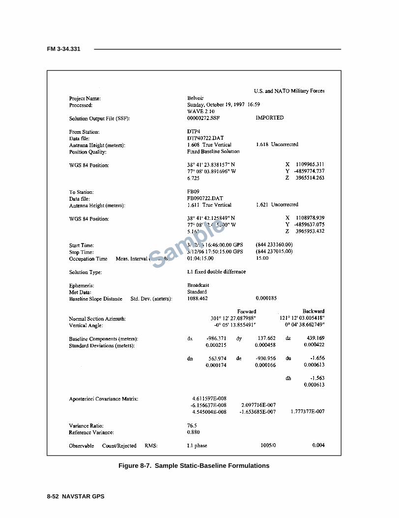
FM 3-34.331
Figure 8-7. Sample Static-Baseline Formulations
8-52 NAVSTAR GPS

FM 3-34.331
LOOP-CLOSURE SOFTWARE
8-200. The internal closure determines the consistency of the GPSmeasurements. Internal closures are applicable for loop traverses and GPSnetworks. It is required that one baseline in the loop be independent. Anindependent baseline is observed during a different session or different day.Many of the better postprocessing software packages come with a loop-closureprogram. Refer to the user’s manual for the particulars of the loop-closureprogram.
GENERAL LOOP-CLOSURE COMPUTATION
8-201. If the postprocessing software does not contain a loop-closure program,the user can perform a loop-closure computation as described in the followingsteps.
Step 1. List the ∆X, ∆Y, ∆Z, and the distance components for all baselinesused in the loop closure.Step 2. Sum the ∆X, ∆Y, ∆Z, and the distance components for all baselinesused in the loop closure.Step 3. Add the square of each of the summations together and then take thesquare root of this sum. This resultant value is the misclosure vector for theloop.Step 4. Calculate the loop-misclosure ratio as follows:
where—m = misclosure vector for the loopL = total-loop distance (perimeter distance)
8-202. The resultant value can be expressed as 1:loop-misclosure ratio. Allunits for the expressions are stated in terms of the units used in the baselineformulations (for example, meters, feet, or millimeters).
EXTERNAL CLOSURES
8-203. External closures are computed in a manner similar to internal loops.External closures provide information on how well the GPS measurementsconform to the local coordinate system. Before the closure of each traverse iscomputed, the latitude, the longitude, and the ellipsoid height must beconverted to geocentric coordinates (X, Y, and Z). If the ellipsoid height is notknown, geoid-modeling software can be used with the orthometric height toget an approximate ellipsoid height. The external closure aids in determiningthe quality of the known control and how well the GPS measurementsconform to the local network. If the control stations are not of equal precision,the external closures will usually reflect the lower-order station. If theinternal closure meets the requirements of the job but the external closure ispoor, the known control is probably deficient and an additional known controlpoint should be included in the system.
Loop-misclosure ratiomL----=
NAVSTAR GPS 8-53

FM 3-34.331
DATA ARCHIVAL
8-204. The raw data is the data recorded during the observation period. Rawdata should be stored on an appropriate medium (such as a floppy disk, aportable hard drive, or a magnetic tape). The raw data and the hard copy ofthe baseline reduction (resultant baseline formulations) should be stored atthe discretion of each unit’s command.
8-205. Differential carrier-phase GPS-S observations are adjusted the sameas conventional-survey observations. Each 3D GPS-baseline vector is treatedas a separate distance observation and adjusted as part of a network. Avariety of methods may be used to adjust the observed GPS baselines to fitexisting control. Since GPS-S networks often contain redundant observations,they are usually adjusted by some type of a rigorous least-squares-minimization method. This section describes some of the methods used toperform horizontal GPS-S adjustments and provides guidance on evaluatingthe adequacy and accuracy of the adjustment results.
GPS ERROR-MEASUREMENT STATISTICAL TERMS
8-206. To understand the adjustment results of a GPS-S, some simplestatistical terms are defined—
• Accuracy. Accuracy is how close a measurement or a group ofmeasurements are in relation to a true or known value.
• Precision. Precision is how close a group or sample of measurementsare to each other. For example, a low standard deviation indicateshigh precision. A survey or group of measurements can have a highprecision but a low accuracy (for example, measurements are closetogether but not close to the known or true value).
• Standard deviation. The standard deviation is a range of how closethe measured values are from the arithmetic average. A low standarddeviation indicates that the observations or measurements are closetogether.
ADJUSTMENT CONSIDERATIONS
8-207. Although vertical elevations are necessarily carried through thebaseline reduction and adjustment process, the relative accuracy of theseelevations is normally inadequate for engineering and construction purposes.Special procedures and constraints are necessary to determine approximateorthometric elevations from relative GPS observations.
8-208. The baseline-reduction process provides the raw relative-positioncoordinates that are used in a 3D GPS-network adjustment. In addition, anddepending on the software, each reduced baseline will contain variousorientation parameters, covariance matrices, and cofactor and/or correlationstatistics that may be used in weighting the final network adjustment. Mostleast-squares adjustments use the accuracy or correlation statistics from the
SECTION VII - PRECISE-POSITIONING SURVEY ADJUSTMENTS
8-54 NAVSTAR GPS

FM 3-34.331
baseline reduction; however, other weighting methods may be used in a least-squares or approximate adjustment.
8-209. The adjustment procedure employed (and the time devoted to it) mustbe commensurate with the project's accuracy requirements. Care must betaken to prevent the adjustment process from becoming a project in itself.There is no specific requirement for performing a rigorous least-squaresadjustment on topographic surveys, whether conventional, GPS, or mixedobservations. Traditional approximate-adjustment methods may be used inlieu of the least-squares method and will provide comparable, practicalaccuracy results.
8-210. Commercial software packages designed for high-order geodetic-densification surveys often contain a degree of statistical sophistication that isunnecessary for engineering survey-control densification (for example, second-order or less). The distinction between geodetic surveying and engineeringsurveying must be fully considered when performing GPS-S adjustments andanalyzing the results.
8-211. Connections and adjustments to existing control networks, such as theNGRS, must not become independent projects. It is far more important toestablish dense and accurate local-project control than to consume resourcestying into first-order NGRS points that are miles from the project.Engineering, artillery, construction, and property/boundary referencingrequires consistent local control with high relative accuracy. Accurateconnections/references to distant geodetic datums are of secondary importance(exceptions are projects in support of military aviation operations). GPS-surveying technology has provided a cost-effective means of tying previouslyestablished, poorly connected projects to the NGRS and simultaneouslytransforming the project to the newly defined NAD 83. In adjusting theseconnections, do not distort or warp long-established project reference points.
SURVEY ACCURACY
8-212. The accuracy of a survey (whether performed using conventional orGPS methods) is a measure of the difference between observed and truevalues (such as, coordinates, distance, or angle). Since the true values arerarely known, only estimates of survey accuracy can be made. These estimatesmay be based on the internal observation closures (such as on a loop traverse)or connections with previously surveyed points assumed to have some degreeof reliability.
8-213. GPS internal accuracies are typically far superior to most previouscontrol networks (including the NAD-83 NGRS). Therefore, determining theaccuracy of a GPS-S based on misclosures with external points is not alwaysvalid unless statistical-accuracy estimates (for example, station variance-covariance matrices or distance/azimuth relative accuracy estimates) from theexternal network’s original adjustments are incorporated into the closureanalysis for a new GPS-S.
8-214. Most survey specifications and standards classify accuracy as afunction of the resultant relative accuracy between two usually adjacentpoints in a network. This resultant relative accuracy is estimated from the
NAVSTAR GPS 8-55

FM 3-34.331
statistics in an adjustment and is defined by the size of a 2D or 3D relativeerror ellipse formed between the two points. Relative distance-, azimuth-, orelevation-accuracy specifications and classifications are derived from thismodel and are expressed either in absolute values (for example, ±1.2centimeters or ±3.5 inches) or as ratios of the propagated standard errors tothe overall length (for example, 1:20,000).
INTERNAL ACCURACY
8-215. A loop traverse that originates and ends from a single point will have amisclosure when observations (for example, EDM traverse angles/distances orGPS-baseline vectors) are computed forward around the loop and back to thestarting point. The forward-computed misclosure provides an estimate of therelative or internal accuracy of the observations in the traverse loop, or moredirectly, the internal precision of the survey. This is perhaps the simplestmethod of evaluating the adequacy of a survey. These point misclosures(usually expressed as ratios) are not the same as relative distance accuracies).
8-216. Internal-accuracy estimates made relative to a single fixed point areobtained when free, unconstrained, or minimally constrained adjustments areperformed. In the case of a single loop, no redundant observations (oralternate loops) back to the fixed point are available. When a series of GPS-baseline loops (or networks) are observed, then the various paths back to thesingle fixed point provide multiple position computations. This allows for astatistical analysis of the internal accuracy of not only the position closure butalso the relative accuracies of the individual points in the network (includingrelative distance- and azimuth-accuracy estimates between these points). Themagnitude of these relative internal-accuracy estimates (on a freeadjustment) determines the adequacy of the control for subsequent design,construction, and mapping work.
8-217. Loop traverses are not recommended for most conventional surveysdue to potential systematic distance or orientation errors, which can becarried through the network undetected. FGCS classification standards forgeodetic surveys do not allow traverses to start and terminate at a singlepoint. Such techniques are unacceptable for incorporation into the NGRSnetwork. However, due to many factors (primarily economic), loop traverses oropen-ended spur lines are commonly employed in densifying project control forengineering and construction projects. Since such control is not intended forinclusion in the NGRS and usually covers limited project ranges, thesepractices have been acceptable for GPS-Ss that are performed in support ofsimilar engineering and construction activities.
EXTERNAL ACCURACY
8-218. The coordinates (and reference orientation) of a single, fixed startingpoint will also have some degree of accuracy relative to the network in whichit is located (such as the NGRS if it was established relative to the system/datum). This external accuracy (or inaccuracy) is carried forward in thetraverse loop or network; however, any such external variance (if small) isgenerally not critical to engineering and construction projects. When a surveyis conducted relative to two or more points on an existing reference network(such as project control or the NGRS), misclosures with these fixed control
8-56 NAVSTAR GPS

FM 3-34.331
points provide an estimate of the absolute accuracy of the survey. Thisanalysis is usually obtained from a final adjustment (usually a fullyconstrained least-squares-minimization method) or by another recognizedtraverse-adjustment method (for example, a transit or a compass).
8-219. This absolute accuracy estimate assumes that the fixed (existing)control is superior to the survey being performed and that any positionmisclosures at connecting points are due to internal observational errors andnot the existing control. This has always been a long-established and practicalassumption and has considerable legal basis in property/boundary surveying.New work is rigidly adjusted to existing control regardless of known orunknown deficiencies in the fixed network.
8-220. Since the relative positional accuracies of points on the NGRS areknown from the NAD-83 readjustment and GPS-baseline-vector accuracyestimates are obtained from individual reductions, variations in misclosuresin GPS-Ss are not always due totally to errors in the GPS work. Forcing a GPStraverse/network to rigidly fit the existing (fixed) network usually results in adegradation of the internal accuracy of the GPS-S, as compared with a free orunconstrained adjustment.
INTERNAL VERSUS EXTERNAL ACCURACY
8-221. Conventional geodetic surveying is largely concerned with absoluteaccuracy or the best fit of intermediate surveys between points on a nationalcontrol network, such as the NGRS. Alternatively, in engineering andconstruction surveying and to a major extent in relative- or local-boundarysurveying, accuracies are more critical to the project at hand. Thus, theabsolute NAD-27 or NAD-83 coordinates (in latitude and longitude) relative tothe NGRS datum reference are of less importance; however, accurate relativecoordinates for a given project are critical to design and construction.
8-222. For example, when establishing basic mapping and construction-layout control for a military installation, developing a dense and accurateinternal relative-control network is far more important than considering thevalues of the coordinates relative to the NGRS. Surveys performed with GPS-S, and the final adjustment thereof, should be configured/designed toestablish accurate relative (local) project control. This is of secondaryimportance in connection with NGRS networks.
8-223. Although reference connections with the NGRS are desirable andrecommended and should be made where feasible and practicable, it is criticalthat such connections (and subsequent adjustments thereto) do not distort theinternal accuracy of intermediate points from which design, construction, orproject boundaries are referenced. Connections and adjustments to distantnetworks (for example, NGRS) can result in mixed datums within a projectarea, especially if not all existing project control has been tied in. This canlead to errors and contract disputes during both design and construction. Onexisting projects with long-established reference control, connections andadjustments to outside reference datums/networks should be performed withcaution. The impacts on legal-property and project-alignment definitions mustalso be considered before such connections.
NAVSTAR GPS 8-57

FM 3-34.331
8-224. On newly authorized projects or on projects where existing projectcontrol has been largely destroyed, reconnection with the NGRS is highlyrecommended. This will ensure that future work is supported by a reliableand consistent basic network, while minimizing errors associated with mixeddatums.
ADJUSTMENTS
8-225. GPS-Ss are usually adjusted and analyzed relative to their internalconsistency and external fit with existing control. The internal-consistencyadjustment (for example, free or minimally constrained) is important from amission compliance standpoint. The final (or constrained) adjustment fits theGPS-S to the existing network. This is not always easily accomplished sinceexisting networks often have lower relative accuracies than the GPSobservations being fit. The evaluation of a survey’s adequacy should not bebased solely on the results of a constrained adjustment.
INTERNAL ADJUSTMENT
8-226. An internal (or geometric) adjustment (also referred to as a freeadjustment) is made to determine how well the baseline observations closeinternally or fit within themselves. Other EDM distances or angles may alsobe included in the adjustment. This adjustment provides a measure of theinternal precision of the survey.
8-227. In a simplified example, a conventional EDM traverse that is loopedback to the starting point will misclose in both azimuth and position.Conventional approximate-adjustment methods will typically assess andproportionately adjust the azimuth misclosure (usually evenly per station),recompute the traverse with the adjusted azimuths, and obtain a positionmisclosure. This position misclosure (in X and Y) is then distributed among allthe points on the traverse using various weighting methods (for example,distance, latitudes, or departures). Final-adjusted azimuths and distances arethen computed from grid inverses between the adjusted points. The adequacy/accuracy of such a traverse is evaluated based on the azimuth misclosure andthe position misclosure after the azimuth adjustment (usually expressed as aratio to the overall length of the traverse).
8-228. A least-squares adjustment of the same conventional loop traverse willend up adjusting the points similarly to the approximate methodstraditionally employed. The only difference is that a least-squares adjustmentsimultaneously adjusts both the observed angles (or directions) and thedistance measurements. A least-squares adjustment also allows variableweighting to be set for individual angle/distance observations, which is asomewhat more complex process when approximate adjustments areperformed. In addition, a least-squares adjustment will yield more definitivestatistical results of the internal accuracies of each observation and/or point,rather than just the final closure. This includes estimates of the accuracies ofindividual station coordinates, relative azimuths, and relative distances.
8-229. A series of GPS baselines forming a loop off a single point can beadjusted and assessed similarly to a conventional-EDM traverse loopdescribed above. The baseline-vector components may be computed
8-58 NAVSTAR GPS
FM 3-34.331
(accumulated) around the loop with a resultant 3D misclosure back at thestarting point. These misclosures (in X, Y, and Z) may be adjusted using eitherapproximate or least-squares methods. The method by which the misclosure isdistributed among the intermediate points in the traverse is a function of theweighting adjustment.
8-230. In the case of a simple EDM traverse adjustment, the observeddistances (or position corrections) are weighted as a function of the segmentlength and the overall traverse length or the overall sum of the latitudes/departures (transit rule). Two-dimensional EDM distance observations arenot dependent on their direction (a distance’s X and Y components areuncorrelated).
8-231. GPS-baseline-vector components (in X, Y, and Z) are correlated due tothe geometry of the satellite solution (the direction of the baseline vector issignificant). Since satellite geometry is continuously changing, remeasuredbaselines will have different correlations between the vector components.Such data are passed down from the baseline-reduction software for use in theadjustment.
8-232. The magnitude of the misclosure of the GPS-baseline vectors at theinitial point provides an estimate of the internal precision or geometricconsistency of the loop (survey). When this misclosure is divided by the overalllength of the baselines, a relative internal-accuracy estimate results. Thismisclosure ratio should not be less than the relative distance accuracyintended for the survey. For example, if the position misclosure of a GPS loopis 0.08 meter and the length of the loop is 8,000 meters, then the loop closureis 0.08 divided by 8,000, which equals 1:100,000.
8-233. When an adjustment is performed, the individual corrections/adjustments made to each baseline (so-called residual errors) provide anaccuracy assessment for each baseline segment. A least-squares adjustmentcan also provide relative distance-accuracy estimates for each line, based onthe standard-error propagation between the adjusted points. This relativedistance-accuracy estimate is most critical in engineering and constructionwork and represents the primary basis for assessing the acceptability of asurvey.
EXTERNAL ADJUSTMENT
8-234. An external (or fully-constrained) adjustment is the process used tobest fit the survey observations to the established reference system. Theinternal, free adjustment provides adjusted positions relative to a single, oftenarbitrary, fixed point. Most conventional or GPS-Ss are connected betweenexisting stations on some predefined reference network or datum. These fixedstations may be existing project-control points (on NAD 27) or stations on theNGRS (NAD 83). In OCONUS locales, other local or regional referencesystems may be used.
8-235. A simple, conventional-EDM traverse between two fixed stations bestillustrates the process by which comparable GPS-baseline vectors areadjusted. As with the loop traverse, the misclosure in azimuth and positionbetween the two fixed points may be adjusted by any type of approximate orleast-squares-adjustment method. Unlike a loop traverse, however, the
NAVSTAR GPS 8-59

FM 3-34.331
azimuth and position misclosures are not wholly dependent on the internalerrors in the traverse—the fixed points and their azimuth references are notabsolute but contain relative inaccuracies with respect to one another.
8-236. A GPS-S between the same two fixed points also contains a 3D positionmisclosure. Due to positional uncertainties in the two fixed points, thismisclosure may (and usually does) far exceed the internal accuracy of the rawGPS observations. As with a conventional-EDM traverse, the 3D misclosuresmay be approximately adjusted by proportionately distributing them over theintermediate points. A least-squares adjustment will also accomplish thesame thing.
8-237. For example, if a GPS-S is looped back to the initial point, the free-adjustment misclosure at the initial point may be compared with theapparent-position misclosure at the other fixed point. A free-adjustment loopmisclosure is 1:100,000, whereas the misclosure relative to the two network-control points is only 1:5,000. Thus, the relative internal accuracy of a GPS-Sis about 1:100,000 (based on the misclosure). If the GPS-baseline observationsare constrained to fit the existing control, the 0.6-meter external misclosuremust be distributed among the individual baselines to force a fit between thetwo end points.
8-238. After a constrained adjustment, the absolute-position misclosure of0.6 meter causes the relative distance accuracies between individual points todegrade. They will be somewhat better than 1:5,000 but far less than 1:10,000.The statistical results from a constrained least-squares adjustment willprovide estimates of the relative accuracies between individual points on thetraverse.
8-239. This example illustrates the advantages of measuring the baselinebetween fixed network points when performing GPS-Ss, especially when weakcontrol is suspected. Also illustrated is the need for making additional ties tothe existing network. In this example, one of the two fixed points was poorlycontrolled when it was originally established or the two points may have beenestablished from independent networks (for example, were never connected).A third or even fourth fixed point would be beneficial in resolving such a case.
8-240. If the intent of the survey in this example was to establish 1:20,000relative-accuracy control, connecting between these two points would notprovide that accuracy, given the amount of adjustment that must be appliedto force a fit. For example, if one of the individual baseline vectors wasmeasured at 600 meters and the constrained adjustment applied a 0.09-metercorrection in this sector, the relative accuracy of this segment would beroughly 1:6,666. This distortion is not acceptable for subsequent design/construction work.
8-241. Most GPS-S networks are more complex than a simple traverse. Theymay consist of multiple loops and may connect with any number of controlpoints on the existing network. In addition, conventional EDMs anddifferential-leveling and angle measurements may be included with the GPSbaselines, resulting in a complex network with many adjustment conditions.
8-60 NAVSTAR GPS

FM 3-34.331
PARTIALLY CONSTRAINED ADJUSTMENTS
8-242. In the previous example of a simple GPS traverse, holding the twonetwork points rigidly caused an adverse degradation in the GPS-S because ofthe differences between the free (loop) adjustment and the fully constrainedadjustment. Another alternative is to perform a partially constrainedadjustment of the network. In a partially constrained adjustment, the twonetwork points are not rigidly fixed but are only partially fixed in position.Partially constrained adjustments are not practicable using approximate-adjustment methods.
8-243. For example, if the relative distance accuracy between the two fixedpoints is about 1:10,000, it can be equated to a positional uncertainty betweenthese points. Depending on the type and capabilities of the least-squares-adjustment software, the higher-accuracy GPS-baseline observations can bebest fit between the two end points, such that the end points of the GPSnetwork are not rigidly constrained to the original two control points but endup falling near them.
8-244. Adjustment software allows relative weighting of the fixed points toprovide a partially constrained adjustment. Any number of fixed points can beconnected, and these points may be given partial constraints in theadjustment. Performing partially constrained adjustments (as opposed to fullyconstrained adjustments) takes advantage of the inherent higher-accuracyGPS data relative to the existing network control. Less warping of the GPSdata (due to poor existing networks) will occur.
8-245. A partial constraint also lessens the need for performing numeroustrial-and-error constrained adjustments in attempts to locate poor externalcontrol points causing high residuals. Fewer ties to the existing network areneeded if the purpose of such ties is to find a best fit on a fully constrainedadjustment.
8-246. When connections are made to NAD 83, relative accuracy estimates ofNGRS stations can be obtained from the NGS. Depending on the type ofadjustment software, these partial constraints may be in the form of variance-covariance matrices, error ellipses, or circular accuracy estimates.
RIGOROUS LEAST-SQUARES ADJUSTMENT
8-247. Adjustment of GPS networks on PCs is typically a trail-and-errorprocess for both the free and the constrained adjustments. When a least-squares adjustment is performed on a network of GPS observations, theadjustment software will provide 2D- or 3D-coordinate accuracy estimates,variance-covariance matrix data for the adjusted coordinates, and relatederror-ellipse data. Most software programs provide relative accuracyestimates (length and azimuth) between points. Analyzing these variousstatistics is not easy, and they are also easily misinterpreted. Arbitraryrejection and readjustment to obtain a best fit must be avoided. The originaldata-reject criteria must be established and justified in a final report.
8-248. When a series of loops are formed relative to a fixed point or offanother loop, different redundant conditions are formed (this is comparable toloops formed in conventional-differential leveling networks). These different
NAVSTAR GPS 8-61

FM 3-34.331
loops allow forward baseline-vector position computations to be made overdifferent paths. From the different routes (loops) formed, different positionalclosures at a single fixed point results. These variances in position misclosuresfrom the different routes provide additional data for assessing the internalconsistency of the network, in addition to checking for blunders in theindividual baselines. The number of different paths, or conditions, is partiallyrelated to the number of degrees of freedom in the network.
8-249. Multiple baseline observations provide additional redundancy orstrength to a line or network since they are observed at two distinct times ofvarying satellite geometry and conditions. The amount of redundancyrequired is a function of the accuracy requirements of the survey. Performinga free adjustment on a complex network containing many redundancies is bestperformed using a least-squares method. Approximate-adjustment methodsare difficult to evaluate when complex interweaving networks are involved.
8-250. Baseline-reduction vector-component error statistics are usuallycarried down into a least-squares adjustment; however, their use is notmandatory for lower-order engineering surveys. GPS-network least-squaresadjustments can be performed without all the covariance and correlationstatistics from the baseline reduction.
8-251. In practice, any station on the network can be held fixed for all threecoordinates, along with the orientation of the three axes and a network-scaleparameter. Usually one of the higher-order points on the existing network isused.
8-252. Least-squares-adjustment software will output various statistics fromthe free adjustment to assist in detecting blunders and residual outliers in thefree adjustment. Most commercial packages will display the normalizedresidual for each observation (for example, GPS, EDM, angle, or elevation),which is useful in detecting and rejecting residual outliers. The variance ofunit weight is also important in evaluating the overall adequacy of theobserved network. Other statistics (such as chi-square, confidence levels, orhistograms) are usually not significant for lower-order engineering projectsand become totally insignificant if the user is not well versed in statistics andadjustment theory. The use of these statistics to reject data (or to report theresults of an adjustment) without fully understanding their derivation andsource within the network adjustment is not advised.
8-253. Relative positional- and distance-accuracy estimates resulting from afree adjustment of a GPS network are usually excellent in comparison toconventional surveying methods. Loop misclosures and relative distanceaccuracies between points commonly exceed 1:100,000. Relative distance-accuracy estimates between points in a network are determined by errorpropagation in the relative positional standard errors at each end of the tie.Relative accuracy estimates may be derived for resultant distances orazimuths between the points. The relative distance-accuracy estimates arethose typically employed to assess the free and constrained accuracyclassifications, expressed as a ratio (such as 1:80,000). Since each point in thenetwork has its particular position variances, the relative distance accuracypropagated between any two points will also vary throughout the network.
8-62 NAVSTAR GPS

FM 3-34.331
8-254. The minimum value (or the largest ratio) will govern the relativeaccuracy of the overall project. This minimum value (from a free adjustment)is compared with the intended relative accuracy classification of the project toevaluate compliance. However, relative distance-accuracy estimates shouldnot be rigidly evaluated over short lines (less than 500 meters).
8-255. Depending on the size and complexity of the project, large variances inthe propagated relative distance accuracies can result. When a constrainedadjustment is performed, the adequacy of the external fixed stations will havea major impact on the resultant and propagated distance accuracies,especially when connections are made to weak control systems. Properlyweighted, partially constrained adjustments will usually improve thepropagated distance accuracies.
8-256. The primary criteria for assessing the adequacy of a particular GPS-Sis the relative distance-accuracy results from a minimally constrained freeadjustment, not a fully constrained adjustment. This is due to the difficulty inassessing the adequacy of the surrounding network. If the propagated relativeaccuracies fall below the specified level, then reobservation is warranted.
8-257. If the relative distance accuracies significantly degrade theconstrained adjustment (due to the inadequacy of the surrounding network),any additional connections to the network would represent a change incontract scope. A large variance of unit weight usually results in such cases.
8-258. If only approximate adjustments are performed, then the relativedistance accuracies may be estimated as a function of the loop or positionmisclosure or the residual corrections to each observed length. For example, ifa particular loop or line miscloses by 1:100,000, then individual-baselinerelative accuracies can be assumed to be adequate if only a 1:20,000 survey isrequired.
8-259. Most adjustment software will output the residual corrections to eachobserved baseline-vector component. These residuals indicate the amountthat each segment was corrected in the adjustment. A least-squaresadjustment minimizes the sum of the squares of these baseline residualcorrections.
8-260. Commercial least-squares-adjustment software is available, which willadjust GPS networks using standard PCs. An example of an adjustmentstatistics summary from the software package used by Army topographicsurveyors is shown in Figure 8-8, page 8-64.
8-261. Relative GPS-baseline standard errors can be obtained from thebaseline-reduction output and in some software programs can be directlyinput into the adjustment. These standard errors, along with theircorrelations, are given for each vector component (X, Y, and Z). They areconverted to relative weights in the adjustment. The following typical input(a priori) weighting is commonly used:
• Fixed. ±3 millimeters (latitude) ±5 millimeters (longitude) + 1 ppm±10 millimeters (height) + 1 ppm.
• Float. ±6 millimeters (latitude) ±10 millimeters (longitude) + 2 ppm±10 millimeters (height) + 2 ppm.
NAVSTAR GPS 8-63

FM 3-34.331
Figure 8-8. Continuation of an Adjustment Statistics Summary Example
Sample
8-64 NAVSTAR GPS

FM 3-34.331
These optimum standard errors have been found to be reasonable in standardwork where extremely long baselines are not involved. The use of theseoptimum values is recommended for the first adjustment iteration.
8-262. The adequacy of the initial network weighting described above isindicated by the variance of unit weight, which equals the square of thestandard error of unit weight. The variance of unit weight should rangebetween 0.5 and 1.5 (or the standard error of unit weight should rangebetween 0.7 and 1.2) with an optimum value of 1, signifying the realisticweighting of the GPS-input observations. A large unit variance (forexample, 5) indicates that the initial GPS standard errors were too optimistic(low). A low unit variance (for example, 0.1) indicates that the results from theadjustment were better than the assumed GPS-baseline precisions. This unit-variance test, however, is generally valid only when a statistically significantnumber of observations are involved. This is a function of the number ofdegrees of freedom shown on the adjustment. To calculate the adequacy of aunit weight, a test (such as chi-square) is performed. Failure of such a testindicates that the variance factor may not be valid.
8-263. The input standard errors can easily be juggled to obtain a variance ofunit weight near 1. This trial-and-error technique is generally not a goodpractice. If the input weights are changed, they should not be modified beyondreasonable levels (for example, do not input a GPS standard error of±50 + 50 ppm to get a good unit variance). If input standard errors aremodified, these modifications should be the same for all lines, not just selectedones. Any such modifications of a priori standard errors must be justified inthe adjustment report.
8-264. Changing the magnitude of the input standard errors or weights willnot change the adjusted position or residual results in a free adjustment,provided all weight changes are made equally. Although the referencevariance will change, the resultant precisions (relative line accuracies) willnot change (this is not true in a constrained adjustment). Therefore, theinternal accuracy of a survey can be assessed based on the free-adjustmentline accuracies regardless of the initial weighting or variance of unit weight.
8-265. The magnitude of the residual corrections may be assessed by lookingfor blunders or outliers; however, this assessment should be performed inconjunction with the related, normalized- or standardized-residual statistic.This statistic is obtained by multiplying the residual by the square root of theinput weight (the inverse of the square of the standard error). If theobservations are properly weighted, the normalized residuals should bearound 1. Most adjustment software will flag normalized residuals thatexceed selected statistical outlier tests. Such residuals are candidates forrejection. As a rule of thumb, reject criterion should be set at three times thestandard error of unit weight, provided that the standard error of unit weightis within the acceptable range given above. All rejected GPS observationsmust be justified in the adjustment report, and the test used to remove theobservation from the file must be clearly described.
8-266. Error ellipses, or 3D error ellipsoids, generated from the adjustmentvariance-covariance matrices for each adjusted point are also useful indepicting the relative positional accuracy. The scale of the ellipse may be
NAVSTAR GPS 8-65

FM 3-34.331
varied as a result of the 2-deviation function. A 2.45 sigma (or 95 percent)probability ellipse is usually selected for output. The size of the error-ellipse’srelative distance or the azimuth-accuracy estimate between two adjacentpoints is a direct function of the size of these positional ellipses.
8-267. The relative distance accuracy is used to evaluate the acceptability of asurvey. This is done using a free adjustment. The output is shown as a ratio orin ppm. The resultant ratios must be divided by 2 to equate them to FGCS95 percent criteria. Further details on these statistical evaluations are beyondthe scope of this manual.
8-268. The following is a summary of a network-adjustment sequence(recommended by the NGS) for surveys that are connected with the NGRS:
• A minimally constrained 3D adjustment is performed initially as atool to validate the data, to check for blunders and systematic errors,and to look at the internal consistency of the network.
• A horizontally constrained 3D adjustment is performed by holding allpreviously published horizontal-control points fixed and using oneheight constraint. All previous observations are considered in theadjustment.
• A fully constrained vertical adjustment is performed to determine theorthometric heights. All previously published BM elevations are heldfixed along with one horizontal position in a 3D adjustment. Geoidheights are predicted using the latest model.
• A final free adjustment is performed and the relative accuracyestimates are computed.
EVALUATION OF ADJUSTMENT RESULTS
8-269. A survey shall be classified based on its horizontal-point closure ratioor its vertical-elevation-difference closure standard (Table 8-7).
HORIZONTAL-CONTROL STANDARDS
8-270. The horizontal-point closure is determined by dividing the linear-distance misclosure of the survey into the overall circuit length of a traverse,loop, or network line/circuit. When independent directions or angles areobserved (for example, a conventional survey [traverse or triangulation]),these angular misclosures may be distributed before assessing positionalmisclosure. In cases where GPS vectors are measured in geocentriccoordinates, the 3D positional misclosure is assessed.
Approximate Surveying
8-271. Approximate surveying is classified based on the survey’s estimated orobserved positional errors. This includes absolute GPS and some DGPStechniques with positional accuracies ranging from 10 to 150 feet (2-deviationRMS). There is no order of classification for approximate work.
8-66 NAVSTAR GPS
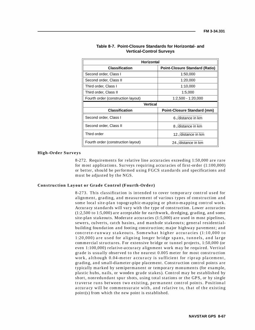
FM 3-34.331
High-Order Surveys
8-272. Requirements for relative line accuracies exceeding 1:50,000 are rarefor most applications. Surveys requiring accuracies of first-order (1:100,000)or better, should be performed using FGCS standards and specifications andmust be adjusted by the NGS.
Construction Layout or Grade Control (Fourth-Order)
8-273. This classification is intended to cover temporary control used foralignment, grading, and measurement of various types of construction andsome local site-plan topographic-mapping or photo-mapping control work.Accuracy standards will vary with the type of construction. Lower accuracies(1:2,500 to 1:5,000) are acceptable for earthwork, dredging, grading, and somesite-plan stakeouts. Moderate accuracies (1:5,000) are used in most pipelines,sewers, culverts, catch basins, and manhole stakeouts; general residential-building foundation and footing construction; major highway pavement; andconcrete-runway stakeouts. Somewhat higher accuracies (1:10,000 to1:20,000) are used for aligning longer bridge spans, tunnels, and largecommercial structures. For extensive bridge or tunnel projects, 1:50,000 (oreven 1:100,000) relative-accuracy alignment work may be required. Verticalgrade is usually observed to the nearest 0.005 meter for most constructionwork, although 0.04-meter accuracy is sufficient for riprap placement,grading, and small-diameter-pipe placement. Construction control points aretypically marked by semipermanent or temporary monuments (for example,plastic hubs, nails, or wooden grade stakes). Control may be established byshort, nonredundant spur shots, using total stations or the GPS, or by singletraverse runs between two existing, permanent control points. Positionalaccuracy will be commensurate with, and relative to, that of the existingpoint(s) from which the new point is established.
Table 8-7. Point-Closure Standards for Horizontal- andVertical-Control Surveys
Horizontal
Classification Point-Closure Standard (Ratio)
Second order, Class I 1:50,000
Second order, Class II 1:20,000
Third order, Class I 1:10,000
Third order, Class II 1:5,000
Fourth order (construction layout) 1:2,500 - 1:20,000
Vertical
Classification Point-Closure Standard (mm)
Second order, Class I
Second order, Class II
Third order
Fourth order (construction layout)
6 distance in km
8 distance in km
12 distance in km
24 distance in km
NAVSTAR GPS 8-67

FM 3-34.331
VERTICAL-CONTROL STANDARDS
8-274. The vertical accuracy of a survey is determined by the elevationmisclosure within a level section or level loop. For differential or trigonometricleveling, section or loop misclosures (in millimeters) shall not exceed thelimits shown in Table 8-7, page 8-67, where the line or circuit length ismeasured in kilometers. Fourth-order accuracies are intended forconstruction-layout grading work. Procedural specifications or restrictionspertaining to vertical-control surveying or equipment should not be overrestrictive.
FINAL-ADJUSTMENT REPORTS
8-275. A variety of free- and/or constrained-adjustment combinations may bespecified for a GPS-S. Specific stations to be held fixed may be indicated, andwhen they are partially constrained, appropriate statistical information mustbe provided. Either variance-covariance matrices or relative positional-accuracy estimates may be converted as approximate variance-covariancematrices in the constrained adjustment. All rejected observations will beclearly indicated, along with the criteria and the reason used for the rejection.
8-276. When different combinations of constrained adjustments areperformed due to indications of one or more fixed stations causing unduebiasing of the data, an analysis should be made as to a recommended solutionthat provides the best fit for the network. Any fixed control points that shouldbe readjusted to anomalies from the adjustment(s) should be clearly indicatedin a final recommendation.
8-277. The final-adjusted horizontal- and/or vertical-coordinate values areassigned an accuracy classification based on the adjustment statisticalresults. This classification should include the resultant geodetic or Cartesiancoordinates and the baseline-differential results. The final-adjustedcoordinates should state the 95 percent confidence region of each point andthe accuracy in ppm between all points in the network. The datum will beclearly identified for all coordinate listings.
8-278. Final-report coordinate listings may be required on hard copy as wellas specified computer media. A scaled plot should be submitted with theadjustment report showing the proper locations and designations of allstations established.
8-68 NAVSTAR GPS

Chapter 9
Artillery Surveys
Topographic-engineer companies are the primary source of topographicsupport throughout the echelons above corps (EAC) and GS. Topographiccompanies support artillery surveys by—
• Extending horizontal and vertical control into the corps and divisionareas.
• Providing a survey planning and coordination element (SPCE) insupport of the EAC.
• Providing mapping-survey control where required.• Advising on topographic matters.• Assisting in lower-level surveys to augment FA surveys.
This chapter defines topographic-survey-operation terms for precisepositioning and orientation at division, corps, EAC, and joint-levelcommands for support of FA and ADA. The accuracy, timeliness, anddistribution of positioning and orientation information and organicequipment are also addressed.
US ARMY FA
9-1. The FA is a primary user of precise-positioning and -orientationinformation in a wartime environment. Topographic-survey support must beprovided to MLRS units, corps’s GS units, and other nondivisional assets inthe corps area. The FA requires that topographic surveyors—
• Establish and recover monumented SCPs (horizontal and vertical)and azimuthal references for conventional and inertial FA surveyteams.
• Coordinate the exact position of the high-order control with the corps’ssurvey officer.
• Augment FA survey sections when appropriate.
ACCURACY
9-2. Established SCPs provide the FA a horizontal, vertical, and azimuthalreference. The horizontal and vertical coordinates and the azimuthalreference station must satisfy FGCS standards and specifications for third-order conventional and satellite positioning.
FREQUENCY AND TIMELINESS
9-3. The FA requires that initial SCPs be established within 5 kilometers ofdivision artillery (DIVARTY) and TA battery (TAB) surveyor’s HQ. Inaddition, a common grid must be established for the AO and should include an
Artillery Surveys 9-1

FM 3-34.331
SCP and azimuthal reference every 30 kilometers. In a wartime scenario,SCPs and azimuthal references are to be established within 30 minutes ofnotification. Topographic surveyors are required to establish third-order SCPsfor the beginning and ending points for each PADS traverse used by MLRSand FA units. The distance interval between these SCPs should be 25 to 30kilometers throughout the division or the corps area. A precise GPS-S is theonly expedient way to emplace third-order SCPs over this distance. Thenumber of SCPs that a topographic survey must provide for the EAC andcorps areas depend on the dispersion, the amount of movement, and thecommander’s priorities. For example, on the basis of five to seven moves perday, 10 to 20 SCPs will be required every 24 hours to support EAC and corpsFA systems that the DIVARTY cannot support.
DISTRIBUTION
9-4. The coordinates that topographic surveyors establish for the FA shouldbe disseminated to the SPCE. The SPCE is the FA’s counterpart to a SIC.SPCEs will be located at HQ and HQ battery (HHB) DIVARTY, corps,brigade, and MLRS battalions. If the SPCE is not in operation, the surveyinformation should be distributed to the operations section S3 or the AssistantChief of Staff, G3 (Operations and Plans) (G3) of the highest element(battalion, brigade, division, or corps). NIMA is many years away frompublishing all maps on the WGS 84, therefore, the commander must be awareof all datums within the AO. Topographic surveyors are responsible fornotifying the SPCE or the appropriate operations section of the variousdatums within the AO. In addition, topographic surveyors should provide theSPCE with the necessary parameters required to transform local coordinatesto the predefined common grid (for example, WGS 84). Since paper mapproducts will not be on a common datum (WGS 84) for many years, it isimperative that topographic surveyors identify these local datum and providethe FA with the necessary transformation parameters. Since map sheets maybe on various local datums (for example, Bosnia, Hungry, or Saudi Arabia),the forward observers (FOs) and the weapon may be on a separate datum. Thecoordinate differences between datums may be hundreds of meters andpositional differences may cause friendly-fire casualties or missed targets.
ADA
9-5. The ADA requires positioning and orientation information. The ADA andthe FA have agreed that FA surveyors (MOS 82C) will provide the ADA withsurvey support, to include the following:
• Accuracy. The ADA’s positional and orientation accuracies are thesame as the FA requirements.
• Frequency and timeliness. Three SCPs per Patriot battalion forarea defense and two SCPs per Patriot battalion for forward-areadefense must be established. The number of SCPs and the timelinessis dependent on the battlefield and the mission.
• Distribution. This control information should be distributed to thehighest echelon SPCE and the Patriot-battalion S3.
9-2 Artillery Surveys

FM 3-34.331
SURVEY PLANNING
9-6. The maneuver commander initiates the requirement for survey planning(reference FM 6-2) by issuing guidance to the fire-support (FS) coordinator(FSCOORD). This guidance states the scheme of maneuver, the rate ofmovement, the anticipated enemy threat, and the critical phases of the battle.
ARTILLERY COMMANDER OR FSCOORD
9-7. The FSCOORD analyzes the commander’s guidance to determine theneed for passing of target information, for having first-round fire-for-effectaccuracy, and for massing of fires. The FSCOORD weighs the analysis againstthe ability to adjust fires, complete registration missions, and engage targetsfrom new position areas. This begins the concept for a survey plan to providecommon survey control.
9-8. The FSCOORD must extract from the maneuver commander’s guidanceall information that allows visualization of the survey requirements for FSassets. The FSCOORD can gain most of the information by reviewing thescheme of maneuver, the rate of movement, the effects required on high-payofftargets, and the accuracy requirements for TA sensors. He must alsodetermine whether it is more important to have survey support at the guns orat the TA assets first.
9-9. Each artillery commander is responsible for establishing common controlthroughout his AO. The FSCOORD must disseminate to the appropriateartillery battalion HQ the established accuracy requirements in survey terms.Additional requirements or guidance derived by the FSCOORD must also becommunicated. This should be done through face-to-face coordination orthrough the S3. The survey officer must be included in this coordination andshould advise the FSCOORD and/or the S3 on the current survey capabilitiesand limitations.
CORPS’S ARTILLERY SURVEY-PLANNING AND COORDINATING OFFICER
9-10. The corps’s artillery survey-planning and coordinating officer (SPCO) isresponsible for the following:
• Knowing the survey requirements and capabilities of all corps units(Figure 9-1, page 9-4).
• Coordinating with the corps’s Assistant Chief of Staff, G2(Intelligence) (G2) to get intelligence estimates of the proposed workareas. These work areas should include—� Enemy activity.� Friendly forces.� Other optional constraints.
• Coordinating with the corps’s G3 to get the following information forplanning and coordinating intelligence and electronic-warfare (IEW)systems that require survey support (Figure 9-2, page 9-5, shows acorps survey-plan overlay).� Positions of the corps’s artillery units (current and planned).� Unit-movement plans.
Artillery Surveys 9-3

FM 3-34.331
� Dates and times of movement.� Priority of unit movement.
• Making contact with the engineer topographic battalion’s surveysection and obtaining necessary details from the commander (forexample, the attached platoon, the location of company SPCE, and thePOCs). The engineer topographic battalions’ survey section supportsthe FA and the ADA with third-order horizontal and vertical controlpoints and azimuth marks for the division through the EAC andseparate artillery brigades on a 24-hour basis. A topographic surveyaugments an FA survey with the information required for thefollowing:� EAC (two SCPs per Patriot battalion).� Corps area (eight SCPs each 24-hour period and one SCP per
DIVARTY or separate brigade each 24-hour period).� PADS (starting and closing SCPs are provided at a maximum
interval of 25 kilometers).
Figure 9-1. Survey Requirements and Capabilities of Corps Units
Corpsartillery
Toposurvey
FA bde
MLRS bn
DIVARTY
C2
C2
C2Comm
GSR FA bde
C2C2
GSFA bn
FAbn
TAB(as
appropriate)
(as appropriate) (as needed)
AN/TPQ-37
AN/TPS-25A AN/TPQ-36FA
btryNBC IEW MET Mortars Engr
4
44
4
4
55
5
3
Coordination only commSurvey control (third order) 3Survey control (fourth order) 4Survey control (fifth order) 5Command and control C2
9-4 Artillery Surveys

FM 3-34.331
Figure 9-2. Corps Survey-Plan Overlay
EW
EW
EW
EW
XX
XX
XX
XX
XXX
XX
XXX
XXX
XXX
Topographic survey
DIVARTY or TAB survey
High-order SCP (established orpreexisting)
SCP established by topographicsurvey
Ground-surveillance radar
Artillery-locating radar
Air-defense radar
Direction-finding site
Electronic warfare
FA bn area
LEGEND:
FEBAFEBA
Artillery Surveys 9-5

FM 3-34.331
� MLRS (starting and closing SCPs are provided at a maximuminterval of 30 kilometers).
• Making necessary arrangements with the corps’s HQ and HQcompany (HHC) for administrative and logistical support of thetopographic survey platoon.
• Arranging and coordinating with the corps’s aviation company forsupport if requested by the survey-section leader of the engineertopographic company.
• Maintaining a close working relationship with the topographic-survey-platoon leader, the corps’s artillery units’ survey officers, andthe DIVARTY survey officers. This coordination ensures a timelythree-way flow of information concerning survey operations and datacollection. It also enhances the timely completion of the surveymission.
9-6 Artillery Surveys
Chapter 10
Airfield-Obstruction and NAVAID Surveys
This chapter acquaints Army surveyors with the terminology and therequirements for airfield-obstruction and NAVAID surveys. The content isgeneral in nature due to the vast differences in airfield instrumentation,customer requirements, and FAA regulations.
AIRPORT OBSTRUCTION CHARTS AND NAVAID SURVEYS
10-1. AOCs and NAVAID surveys are extensive field or photogrammetricoperations that are required by agreement between the FAA and the USAASAand are specified in AR 95-2. Airfield-obstruction and NAVAID surveyingoperations involve obtaining accurate and complete NAVAID and associatedairport/heliport-obstruction and geodetic-positioning data. A precisegeographic position of these navigational facilities is required to support theFAA and a wide range of NAS activities. AOC surveys provide sourceinformation on—
• Runways and stopways.• NAVAIDs.• FAR-77 obstructions.• Aircraft-movement aprons.• Prominent airport buildings.• Selected roads and other traverse ways.• Cultural and natural features of landmark value.• Miscellaneous and special-request items.
10-2. AOC surveys also establish or verify geodetic control in the airportvicinity that is accurately connected to the NSRS. This control and the NSRSconnection ensure accurate relativity between these points on the airport andother surveyed points in the NAS, including GPS navigational satellites. AOCdata is used to—
• Develop instrument-approach and -departure procedures.• Determine maximum takeoff weights.• Certify airports for certain types of operations.• Update official aeronautical publications.• Provide geodetic control for engineering projects related to runway/
taxiway construction, NAVAID positioning, obstruction clearing, andother airport improvements.
• Assist in airport planning and land-use studies.• Support activities such as aircraft-accident investigations and special
projects.
Airfield-Obstruction and NAVAID Surveys 10-1

FM 3-34.331
FAA AND FAR STANDARDS
10-3. FAA Publication 405 (FAA 405) and FAR-77 outline the requirementsfor AOC surveys. Various areas, surfaces, reference points, dimensions, andspecifications used in airfield surveys are described below.
RUNWAYS
10-4. All length and width measurements are determined to the nearest foot.If the runway’s threshold is displaced, the distance (in feet) is given from thebeginning of the runway’s surface. Determine the coordinates (latitude andlongitude) of the runway’s threshold and stop end at the runway’s centerline.Elevations at the runway’s threshold, stop end, and highest elevation (withinthe first 3,000 feet of each runway touchdown zone elevation [TDZE]) shouldbe determined to the nearest 0.1 foot from the MSL. In addition, preparerunway profiles that show the elevations listed above, the runway’s high andlow points, grade changes, and gradients. Determine the elevation of a pointon the instrumented runway’s centerline nearest to the instrument landingsystem (ILS) and the glide-path transmitter to the nearest 0.1-foot MSL.
NAVAIDS
10-5. Airports requiring airfield-obstruction and NAVAID surveys areinstrumented runways. The exact point on the radar, the reflectors, therunway intercepts, and the ILS and microwave-landing-system (MLS)components depend on the survey type, the location, and the requiredaccuracy. The requirement to verify the existing ILS/MLS, their properdescription, and all components on or near the runway is mandatory. Obtaininformation for locating and describing all airfield features with help fromairfield-operation, maintenance-section, and control-tower personnel. Thefollowing NAVAIDs are located on airports:
• ILS.• MLS.• Precision approach radar (PAR).• Airport surveillance radar (ASR).
10-6. The following NAVAIDs are not located on airports:
• Tactical air navigation (TACAN).• VHF omnidirectional range (VOR).• Nondirectional beacon (NDB).• VOR and TACAN (VORTAC).
OBSTRUCTIONS
10-7. An obstruction is an object or feature protruding through or above anynavigational imaginary surface that poses a threat to the safe operation ofaircraft. Navigational imaginary surfaces or obstruction identificationsurfaces (OISs) are defined in FAR-77. In the following paragraphs are somedefinitions, along with some samples.
10-2 Airfield-Obstruction and NAVAID Engineering Surveys

FM 3-34.331
FAR-77, Section 77.28, Military-Airport Imaginary Surfaces (Figure 10-1 andFigure 10-2, page 10-4)
10-8. Related to airport reference points (ARPs). These surfaces apply toall military airports. For the purpose of this section, a military airport is anyairport operated by an armed force of the US.
• Inner horizontal surface. An oval plane that is at a height of150 feet above the established airfield elevation. The plane isconstructed by scribing an arc with a radius of 7,500 feet from the
Figure 10-1. General Plan View of an OIS
LEGEND:A Primary surfaceB Clear-zone surfaceC Approach/departure-clearance surface (glide angle)D Approach/departure-clearance surface (horizontal)E Inner horizontal surfaceF Conical surfaceG Outer horizontal surfaceH Transitional surface
F
E
D16,0
00′
30,0
00′
7,00
0′
7,50
0′
B A
G
500′′′′ above airfield elevation
150′ above airfield elevation
H
Airfield-Obstruction and NAVAID Engineering Surveys 10-3

FM 3-34.331
centerline at the end of each runway and interconnecting these arcswith tangents.
• Conical surface. A surface extending from the periphery of the innerhorizontal surface outward and upward at a slope of 20:1 for ahorizontal distance of 7,000 feet to a height of 500 feet above theestablished airfield elevation.
• Outer horizontal surface. A plane that is located 500 feet above theestablished airfield elevation, extending outward from the outerperiphery of the conical surface for a horizontal distance of30,000 feet.
10-9. Related to runways. These surfaces apply to all military airports.
• Primary surface. A surface located on the ground or on water,longitudinally centered on each runway, and the same length as therunway. The width of the primary surface for runways is 2,000 feet.However, at established bases where substantial construction has
Figure 10-2. Partial Plan View of an OIS
LEGEND:A Primary surfaceB Clear-zone surfaceC Approach/departure-clearance surface
(glide angle) (50:1)D Approach/departure-clearance surface
(horizontal)E Inner horizontal surfaceF Conical surface (20:1)G Outer horizontal surfaceH Transitional surface (7:1)
H
C
D
HE
F
FE GBA
10-4 Airfield-Obstruction and NAVAID Engineering Surveys

FM 3-34.331
taken place according to previous lateral-clearance criteria, the 2,000-foot width may be reduced to the former criteria.
• Clear-zone surface. A surface located on the ground or on water ateach end of the primary surface. The clear-zone surface is 1,000 feetlong and is the same width as the primary surface.
• Approach/departure-clearance surface. An inclined plane that islocated symmetrical from the extended runway’s centerline, beginning200 feet beyond each end of the primary surface at the centerlineelevation of the runway’s end and extending for 50,000 feet(Figure 10-3, page 10-6). The slope of the approach-clearance surfaceis 50:1 along the extended runway’s centerline until it reaches anelevation of 500 feet above the established airport elevation. Thesurface then continues horizontally at this elevation to a point50,000 feet from the beginning point. The width of this surface at therunway’s end is the same as the primary surface, then it flaresuniformly and the width at 50,000 feet is 16,000 feet.
• Transitional surfaces. These surfaces connect the primary surfaces,the first 200 feet of the clear-zone surfaces, and the approach/departure-clearance surfaces to the inner horizontal surface, theconical surface, the outer horizontal surface, or other transitionalsurfaces. The slope of the transitional surface is 7:1 outward andupward at right angles to the runway’s centerline.
FAR-77, Section 77.29, Airport Imaginary Surfaces for Heliports
10-10. These surfaces apply to all military heliports. For the purpose of thissection, a military heliport is any heliport operated by an armed force of theUS.
• Heliport’s primary surface. The primary surface coincides in sizeand shape with the designated takeoff and landing area of a heliport.This surface is a horizontal plane at the elevation of the establishedheliport elevation.
• Heliport’s approach surface. The approach surface begins at eachend of the heliport’s primary surface, is the same width as the primarysurface, and extends outward and upward for a horizontal distance of4,000 feet where its width is 500 feet. The slope of the approachsurface is 8:1 for civil heliports and 10:1 for military heliports.
• Heliport’s transitional surfaces. These surfaces extend outwardand upward from the lateral boundaries of the heliport’s primarysurface and from the approach surfaces at a slope of 2:1 for ahorizontal distance of 250 feet from the centerline of the primary andapproach surfaces.
FAR-77, Section 77.5, Kinds of Objects Affected
10-11. This section further defines an obstruction and applies to—
• Any object of natural growth, the terrain, permanent or temporaryconstruction or alterations (including equipment or materials usedtherein), and apparatus of a permanent or temporary character.
Airfield-Obstruction and NAVAID Engineering Surveys 10-5

FM 3-34.331
Figure 10-3. Plan and Profile View of the Approach/Departure OIS
500′ elevation D
C50:1
Groundsurface
A
A
B
7,500′
7,000′
30,000′
Longitudinal section
25,000′ 25,000′200′
1,000′
C
2,00
0′
D
GH
F
E
Plan view
LEGEND:A Primary surfaceB Clear-zone surfaceC Approach/departure-clearance surface (glide angle)D Approach/departure-clearance surface (horizontal)E Inner horizontal surfaceF Conical surfaceG Outer horizontal surfaceH Transitional surface
10-6 Airfield-Obstruction and NAVAID Engineering Surveys

FM 3-34.331
• Any permanent or temporary existing structure altered by a change inits height (including appurtenances) or lateral dimensions (includingequipment or materials used therein).
DATA
10-12. The ARP location (in longitude and latitude) will be determinedaccording to FAA 405. Field elevation is the highest point on any airportlanding surface.
AIRFIELD-DATA ACCURACY REQUIREMENTS
10-13. All contiguous CONUS-, Alaskan-, and Caribbean-area coordinatesshould be determined based on NAD 83 and/or WGS 84. Geodetic accuracy oforthometric heights are referenced to NAVD 88. The coordinates for the pointson the airport require different degrees of accuracy. Tables 10-1 and 10-2 andTables 10-3 through 10-5, page 10-8, are examples of different accuracystandards for airfield data. FAA 405 contains the complete requirements. Thehorizontal accuracy requirements can be met through third-order, Class IItraverse, GPS, or two-point intersection techniques. The vertical accuracyrequirements dictate a minimum of third-order differential-levelingtechniques.
Table 10-1. Airport-Obstruction Accuracy Requirements
ItemHorizontal
(ft)Orthometric
(ft)Ellipsoidal
(ft)Above Ground
Level (ft)
Non-man-madeobjects and man-made objectsless than 200 feetabove groundlevel thatpenetrate theOISs.
A primary surface. 20 3 3 NA
Those areas of an approachsurface within 10,200 feet ofthe runway’s end.
20 3 3 NA
Those areas of a primarytransitional surface within 500feet of the primary surface.
20 3 3 NA
Those areas of an approach/departure surface that areboth within 500 feet of theapproach surface and within2,766 feet of the runway’s end.
20 3 3 NA
Table 10-2. Visual-NAVAID Accuracy Requirements
ItemHorizontal
(ft)Orthometric
(ft)Ellipsoidal
(ft)Above Ground
Level (ft)
Airport beacon (1) NA NA NA
Visual glide-slope indicators 20 NA NA NA
Runway end identifier lights (REILs) 20 NA NA NA
Approach lights 20 NA NA NA
NOTE: The horizontal accuracy requirement for items coded “(1)” is 20 feet when located on a public-use airport or military airfield and 50 feet for all other locations.
Airfield-Obstruction and NAVAID Engineering Surveys 10-7

FM 3-34.331
REPORTING
10-14. The required reporting for airfield surveys is not significantly differentfrom that required for other survey operations. The parent unit will normallyrequire all of the reports listed in Chapter 11 of this manual. In addition tothese routine reports, a special report (according to ARs 95-1 and 95-2,FAA 405, and FAR-77) will be required for the submission of the final data.For quick reference, the required documentation is listed below.
Table 10-3. Control-Station Accuracy Requirements
ItemHorizontal
(cm)Orthometric
(cm)Ellipsoidal
(cm)Above Ground
Level (cm)
Primary airport control station (PACS)1 5 25.0 15 NA
Secondary airport control station (SACS)2 3 5.0 4 NA
Wide-Area Augmentation System (WAAS)
reference station1 5 10.0 10 NA
WAAS reference station3 1 0.2 2 NA
1Accuracies are relative to the nearest NGS-sanctioned continuously operating reference station.2Accuracies are relative to the PACS and the SACS at the airport.3Accuracies are relative to the other WAAS reference station at the site.
Table 10-4. Electronic-NAVAID Accuracy Requirements
ItemHorizontal
(ft)Orthometric
(ft)Ellipsoidal
(ft)Above Ground
Level (ft)
Air-route surveillance radar (ARSR) (1) 100 100 NA
ASR (1) 10 10 NA
DME:
Frequency paired with localizer
Frequency paired with MLS azimuth guidance
Frequency paired with NDB
Frequency paired with VOR
1
1
(1)
(1)
1
1
NA
NA
1
1
NA
NA
NA
NA
NA
NA
NOTE: The horizontal accuracy requirement for items coded “(1)” is 20 feet when located on a public-useairport or military airfield and 50 feet for all other locations.
Table 10-5. Airport-Runway Accuracy Requirements
ItemHorizontal
(ft)Orthometric
(ft)Ellipsoidal
(ft)Above Ground Level
(ft)
Physical end 1 0.25 0.2 NA
Displaced threshold (DT) 1 0.25 0.2 NA
TDZE NA 0.25 0.2 NA
Supplemental profile points 20 0.25 0.2 NA
10-8 Airfield-Obstruction and NAVAID Engineering Surveys

FM 3-34.331
AOC10-15. An AOC is a 1:12,000-scale graphic depicting FAR-77 guidance. AnAOC represents objects that penetrate airport imaginary surfaces, aircraftmovement and apron areas, NAVAIDs, prominent airport buildings, and aselection of roads and other planimetric detail in the airport vicinity. Alsoincluded are tabulations of runway and other operational data. AOC data iscurrent as of the date of the field survey. The AOC consists of four sections:
• Airport plan (AP).• Runway plans and profiles (RPP).• Tabulated operational data (TOD).• Notes and legends (NL).
10-16. Each section (all contents and the general format) should conform tothe sheet style (obstruction chart [OC] 000) represented in FAA 405. An AOCis published on E50 chart paper (or equivalent) with border dimensions of 30 x42 or 30 x 48 inches. The long dimension may be either in the north-south oreast-west direction and should have a ¾-inch space between the border andthe trim line. If the AP and the RPP will not fit on the front of the chart, theRPP is printed on the back.
Airport Plan
10-17. The depiction of the AP depends on the surface type and whether anobstruction survey was accomplished. A detailed explanation of whatpertinent information to depict is included in FAA 405, Section 10.1.3. Forexample, an AP for a specially prepared hard surface (SPHS) runway willinclude the following information:
• Runway’s length and width.• DTs.• The physical end of the runway.• Airport elevation.• TDZE.• Magnetic bearing.• Runway numbers.• Obstructions.• NAVAIDs.• Meteorological apparatus.• ARP.
Runway Plans and Profiles
10-18. A detailed explanation of what information to depict is included inFAA 405, Section 10.1.4. The RPP should include the following:
• Proper angular orientation.• A horizontal scale of 1:12,000 and a vertical scale of 1 inch equal to
100 feet.• Adequate area of coverage of the primary and approach surfaces.• A plan view of the runway as shown on the AP.• A profile view of objects carried in the plan view.• A profile view of objects penetrating the approach surfaces.
Airfield-Obstruction and NAVAID Engineering Surveys 10-9

FM 3-34.331
• The correct approach surface or precise-instrument-runway (PIR)surface.
• The correct numbering scheme of objects in the profile.• A north arrow.
NOTE: A PIR has an existing instrument-approach procedure that uses an ILS or aPAR. PIR also refers to a runway for which a precision approach system is plannedand is so indicated by an FAA-approved airport layout plan, a military-airport layoutplan, any other FAA planning document, or a military-airport planning document.
Tabulated Operational Data
10-19. The TOD should show the following:
• The airport location point (ALP) listed in degrees and minutes.• The ARP listed in degrees, minutes, and three-decimal-place seconds.• A runway data table with runway numbers, appropriate latitude and
longitude coordinates, and TDZEs.• Geodetic azimuth from the approach end to the stop end, reckoned
from the north.• Additional information pertaining to runways with DTs.
Notes and Legends
10-20. A detailed explanation of what pertinent information to depict isincluded in FAA 405, Section 10.1.6. The NL should include the following:
• Horizontal datum.• Vertical datum.• Map projection.• Airport elevation.• A legend.• Graphic horizontal and vertical scales.
FORMS
10-21. In addition to the AOC, each airfield report requires completion of thefollowing forms:
• DA Form 5821.• DA Form 5822.• DA Form 5827.
10-22. An airfield compilation report (DA Form 5821) (Figure 10-4) is atabulation of all the information obtained from the survey. Table 10-6,page 10-12, includes instructions for completing this form.
10-23. PAR or ground-controlled-approach (GCA) data is entered onDA Form 5822 (Figure 10-5, page 10-13). The completion of this form is self-explanatory.
10-24. ILS data is entered on DA Form 5827 (Figure 10-6, page 10-14). Thecompletion of this form is self-explanatory.
10-10 Airfield-Obstruction and NAVAID Surveys

FM 3-34.331
Figure 10-4. Airfield Compilation Report
30th Engineer Battalion
McCoy Army Airfield CMY
Fort McCoy Wisconsin #1 2001 07 15
43°57′33.458″N 90°44′14.641″W -01°34′15.6″
837.3 MSL EOR 01 871.2 MSL
NDB (CMY)
Windsock (1)
Beacon (13)
WDI
Tetrahedron
Control Tower (9)
Maltese Cross #1
Maltese Cross #2
Maltese Cross #3
1,020.1
860.4
896.4
845.8
834.7
911.6
830.5
829.8
832.9
43°56′16.1″N
43°57′35.7″N
43°57′14.5″N
43°57′35.7″N
43°57′36.1″N
43°57′22.5″N
43°57′30.8″N
43°57′26.4″N
43°57′22.8″N
90°38′30.3″W
90°43′58.5″W
90°44′05.8″W
90°43′58.1″W
90°43′58.4″W
90°44′05.9″W
90°43′59.7″W
90°44′15.9″W
90°43′51.6″W
01/01
01/01
01/01
01/01
01/01
01/01
01/01
01/01
01/01
EOR 29TDZE
EOR 11
TDZE11/29
EOR 19
EOR 01
NA
NA
NA
NA
NA
1,326.7
831.8
822.4
824.7
837.3
EOR 01DT
835.7
43°57′27.478″N
43°57′43.164″N
43°57′32.027″N
43°57′44.922″N
43°57′16.715″N
43°57′04.089″N
90°43′48.699″W
90°44′42.017″W
90°44′03.899″W
90°44′08.802″W
90°44′19.574″W
90°44′24.408″W
100.004,211.00
75.004,211.00
NA
90.002,962.90
90.002,962.90
50.001,326.70
292°09′26.2″290°58′26.2″112°09′25.8″110°58′25.8″
NA
195°25′26.5″194°14′26.5″
15°25′27.3″14°14′27.3″
NA
WGS-84
829.5
ARP
Airfield-Obstruction and NAVAID Surveys 10-11

FM 3-34.331
Table 10-6. Instructions for Completion of DA Form 5821
Block Name Instruction
Survey agency The agency conducting the field survey.
Airport name The official airport name as determined by the FAA.
IdentifierThe airport location-identifier designator as listed in FAA Publication7350.5-V.
City Self-explanatory.
State Self-explanatory.
EditionThe number of times the airfield has been surveyed by the agencylisted in the survey-agency block. Identify the original survey as 1 andsubsequent surveys as 2, 3, and so on.
Survey date The year of declination.
ARP The physical location of the ARP.
ARP latitude Self-explanatory.
ARP longitude Self-explanatory.
Delta azimuth ortheta angle
The grid convergence for the ARP.
ALP The physical location of the ALP.
ALP latitude Self-explanatory.
ALP longitude Self-explanatory.
Declination The magnetic declination of the ARP.
Airport elevation (ft) See the glossary.
Located A short narrative description (include the latitude and the longitude).
Control-tower floorelevation (ft)
Self-explanatory.
Airport data Object or airfield feature observed (use additional sheets as required).
Elevation Self-explanatory.
Airport-data latitude Self-explanatory.
Airport-data longitude Self-explanatory.
Year code The year and month surveyed (for example, April 87 is written 8704).
Remarks Self-explanatory.
Office code Leave blank (may be used by other offices).
Runway The numerical designation of the runway.
DT length See the glossary.
Runway-end elevation Self-explanatory.
Runway-end latitude Self-explanatory.
Runway-end longitude Self-explanatory.
Width/length The physical width and length of the runway’s surface.
Geodetic azimuth/magnetic bearing
Self-explanatory.
Office code Leave blank.
10-12 Airfield-Obstruction and NAVAID Surveys

FM 3-34.331
Figure 10-5. PAR Data
McCoy Army Airfield
Fort McCoy Wisconsin 2001 07 15
EOR 11
43º57′14.51″ 90º44′05.79″
43º57′36.10″
43º57′36.33″
43º57′43.16″
43º57′27.48″
90º43′58.40″
90º43′58.40″
90º44′42.02″
90º43′48.70″
896.4
831.4
829.5
831.8SAMPLE
834.7
N
2
1
Airfield-Obstruction and NAVAID Surveys 10-13

FM 3-34.331
Figure 10-6. ILS Data
43º57′43.16″
43º57′27.48″
90º44′42.02″
90º43′48.70″
829.5
831.8
SAMPLE
McCoy Army Airfield
Fort McCoy Wisconsin 2001 07 15
N
10-14 Airfield-Obstruction and NAVAID Surveys

Chapter 11
Reports, Briefings, and Operation Orders
All survey and survey-support activities must be documented.Additionally, unit commanders or visiting dignitaries have to be informedabout the status of the project. The most common means of accomplishingthese two tasks are reports and briefings. This chapter gives generalguidance and recommended formats for these reports and briefings and foroperation orders (OPORDs). This information is not intended to replaceunit SOPs or official correspondence-preparation guidance but rather tosupplement them and provide for a standardized procedure and format.Section III of this chapter includes a sample survey SOP and supportingannexes.
11-1. All reports should be treated as for official use only (FOUO) andsafeguarded accordingly. In many instances, reports will be classified andappropriate safeguard measures are mandatory. All activities and events of asurvey should be documented in a report. Reports can take many forms, andtheir primary uses are to—
• Provide documentation of the project.• Serve as a historical record of accomplishment on problems.• Inform commanders of project status.• Provide information and data to planners and users.
GENERAL
11-2. All reports may not address each subject, but they will serve at least oneof the above functions. A well-planned survey project can be broken down intophases. Each phase will require at least one report. These phases include—
• Initial site visitation.• Field recon.• Project execution.• Compilation and computing.
11-3. In some situations, it may be convenient and practical to combine one ormore of these phases and to prepare a consolidated report. Reports areprepared to provide information and should not be written just to fulfill arequirement.
SECTION I - REPORTS
Reports, Briefings, and Operation Orders 11-1

FM 3-34.331
ISVT REPORT
11-4. The initial site visitation is usually a preliminary visit that is used togather general information. The information collected is generally used forlogistical purposes. This does not mean that technical information is notgathered, but gathering information is not necessarily the primary function ofthe visit. The initial site visitation will normally be conducted by the survey-section leader and the project’s noncommissioned officer (NCO). Depending onthe nature of the project, the survey-platoon leader may also be included. Inall cases, an ISVT report is required. A battalion or company SOP will usuallydesignate the individual responsible for completing the report as well as theexact format to be used. Annex A of the sample survey SOP shows the formatfor an ISVT report. Any information that could be used at a later date shouldbe included.
11-5. The report should be broken down into readily identifiable numberedand titled paragraphs as follows:
Paragraph 1. References. The project directive or technical OPORD(TECHOPORD) number.
Paragraph 2. Personnel. The name, rank, and telephone number of allpersonnel involved in the recon.
Paragraph 3. Key Personnel Contacts. The name, rank or position title,address, and telephone number of all key individuals contacted whileconducting the visit. This paragraph is often combined with paragraph 2.
Paragraph 4. Objective. The objective of the ISVT.
Paragraph 5. Discussion. A discussion of exactly what occurred and whatconversations took place (include only the most extensive). This paragraphwill contain subparagraphs concerning logistical and technical information.All arrangements for lodging, food, medical, and other support must be listedand should include specific details. Any technical information should be listed;however, if extensive technical details are available, it may be advisable toinclude them in an appendix to the basic report. The key to the discussionparagraph is to list all information that is available. The report may be theonly source of information for later activities on the project.
Paragraph 6. Recommendations. The specific recommendations for theconduct of the next phase of the project. These recommendations shouldinclude the number of personnel, the start date, and the tasks to beaccomplished.
Paragraph 7. Funding. The fund citation. It may also specify the fundsexpended on the ISVT and any information concerning funding of the nextphase of the project.
Paragraph 8. Work Hours. The total number of work hours broken down byrank. This information can be used for projecting the time required on similarfuture projects.
Paragraph 9. Equipment. The type of vehicles; the vehicles’ identificationnumbers; the miles driven; and petroleum, oils, and lubricants (POL)information.
11-2 Reports, Briefings, and Operation Orders

FM 3-34.331
11-6. The report must always be signed. A standard military signature blockshould be used. Any required appendix(es) should be attached. A copy of thereport should be included with the project folder and the original forwarded tothe appropriate commander.
RECON REPORT
11-7. The recon report will typically be longer than the ISVT report. It shouldcontain logistical and technical information. The recon report is broken downinto three major sections—narrative, graphic, and control cards.
NARRATIVE
11-8. The narrative section is somewhat similar to the ISVT report. Itcontains much of the same type of information; however, it will be greatlyexpanded. Any information that could be used at a later date should beincluded. The report should be broken down into readily identifiablenumbered and titled paragraphs (some of the subparagraphs may be deleted ifthey serve no purpose) as follows:
Paragraph 1. References. The project directive or order number. The ISVTreport should be listed if available.
Paragraph 2. Personnel. The name, rank or position title, unit, andtelephone number (both home station and remote site) of all personnelinvolved in the recon.
Paragraph 3. Key Personnel Contacts. The name, rank or position title,address, and telephone number of all personnel, offices, or agencies that werecontacted during the recon (include military message addresses). Thisparagraph is extremely important for rights of way and access to privatelands. Agreements made with landowners and/or property custodians shouldbe listed, and a written permission document should be prepared and signedand a copy included as the last annex of the ISVT report.
Paragraph 4. Objective. The objective of the recon. It should be very specificand should include the nature of the recon (for example, triangulation,traverse, level, or plane table).
Paragraph 5. Discussion. A discussion of the project. This paragraph willtypically be the longest and will normally be broken down into subparagraphs.All details must be listed and specified. The following subparagraphs shouldbe included:
• Administrative, legal, and logistical support. A complete listingof all the support that has been arranged for the project. The listshould include the following information:■ Medical facilities. Identify the nearest military medical facility
for routine medical problems and the nearest emergency medicalfacility.
■ Lodging and mess facilities. List the arrangements, location,and condition of the facilities if the military installation canprovide lodging and messing. Indicate whether or not the use ofthe mess facilities will detract from the execution of the project.
Reports, Briefings, and Operation Orders 11-3

FM 3-34.331
■ Contracts. Include copies of all legal contracts that authorize thesurveyors’ entrance onto private and other nonfederal land.Identify the POC at the JAG that coordinated or generated thedocuments in case future complications or disagreements occur.
■ Controlled areas. List the requirements to be followed if thesurveyors must enter secure or sensitive areas (classifiedequipment or systems). Provide the customer’s security officerwith the names and security classifications of the surveyors beforestarting the project. If the surveyors must be escorted, identify theprimary escort and whether the surveyors can go into thecontrolled area at any time. Identify how access to the controlledareas will affect the scheme of extending survey control.
■ Morale factors. List all arrangements that have been made formail delivery, pay processing, and financial assistance.
■ Other logistic information. List any additional supportinformation that is required. MOAs for POL and other expendablesupplies and vehicle-maintenance support should be included asannexes. Include coordination procedures for any secured area (forexample, a fenced in area that is locked after duty hours).
• Environmental factors. Any environmental factors that could affectthe project. These may include, but are not limited to, the following:■ Weather. The expected weather conditions, to include long-range
forecasts and normal weather patterns for the project area.■ Terrain. The type of terrain to be expected and how it will affect
access to existing and proposed SCPs. How landforms will affectintervisibility and the proposed survey scheme.
■ Flora and fauna. The types of plants and animals that inhabitthe area. Particular attention should be given to poisonous plantsand dangerous animals.
■ Dangerous areas/restricted zones. A brief description of thetype and location of any dangerous areas or restricted zones.Annotate them on the overlay.
• Technical information. A listing of all work that was accomplished(for example, recovery, check angles, and check distances). It shouldalso contain—■ All proposed starting and ending stations and their conditions.■ Line of sight information (also included in the graphic section).■ The accuracy of the figures (if applicable).■ Any other information of a technical nature that the field-survey
party may need to know.• Source materials. A complete list of all source materials (such as
trig lists, data cards, map sheets, and overlays) and the agency oroffice of origin. A copy of these materials should be attached behindthe station description cards.
Paragraph 6. Recommendations. Any recommendations (this paragraphwil l be lengthy and should be very det ai le d) . It sho uld include
11-4 Reports, Briefings, and Operation Orders
FM 3-34.331
recommendations that are based on sound technical principles that are withinthe capabilities of the unit. Include detailed information about the following:
• Methods of survey. The exact methods, procedures, and accuracyrequirements.
• Job estimates. The estimated amount of personnel and time. Usingthis information, a cost estimate should be prepared and containedwithin this paragraph. If it is lengthy, include supporting data sheetsas an annex.
• Equipment. The equipment required to do the job. This will normallybe TOE-authorized equipment; however, in some cases, it may benecessary to obtain other equipment (for example, chain saws).Indicate how and where the equipment will be obtained (for example,a cement mixer from the Directorate of Public Works (DPW), Roadsand Grounds Division).
• Time schedule. The project’s time schedule (if the start date isknown). For lengthy projects that must be broken down into phases, amilestone schedule should be developed and enclosed as an annex.
Paragraph 7. Funding. Funds expended during the recon. Also includeinformation such as the fund citation and source.
Paragraph 8. Work Hours. The work hours expended (broken down by rankand activity performed [for example, POC meetings, POL and maintenancesupport, administrative requirements, and field recon]). This information willbe helpful for planning and estimating similar future projects.
Paragraph 9. Equipment. A list of all the equipment used to conduct therecon. Include the types of vehicles, the vehicles’ identification numbers, themiles driven, POL data, and any other equipment actually used by the reconparty.
GRAPHIC
11-9. This section will usually take the form of overlays and/or maps. Usestandard topographic and military symbols (as listed in FMs 21-31 and101-5-1) when annotating overlays and maps. At a minimum, an overlayshould contain the following information:
• Known, usable survey control stations (horizontal and vertical).• Proposed survey stations.• Dangerous areas and restricted zones. Show on the overlay and on all
available maps.• Other information that will assist the survey project. Include possible
intersection stations that will be visible from several main-schemestations.
CONTROL CARDS
11-10. This section should be a compilation of DA Forms 1958 and 1959 thatwere completed during the recon. The control cards must be complete,accurate, formatted correctly, and of high enough quality to permit them to bereproduced with minimal expenditure of time and labor.
Reports, Briefings, and Operation Orders 11-5

FM 3-34.331
PROGRESS REPORT
11-11. Progress reports are generally less formal than the other types ofreports but are just as important. They are designed to keep the commanderinformed of progress. The time interval for progress reports will beestablished by the commander and included in the project directive. Normally,progress reports will be submitted weekly and, in some cases, daily verbalreports may be required. Progress reports may not be required for smallprojects.
VERBAL
11-12. A verbal report follows the same identical format as a written progressreport. The sender and the receiver should have a copy of the premade formatto follow. Only those lines that are applicable are filled in. The field copy isincluded in the project file for use in compiling a written weekly or end-of-project report.
WRITTEN
11-13. A written progress report normally includes a cover form and a datasheet. The data sheet is a fill-in-the-blank form. Those areas not applicableare left blank. All information must be as accurate as possible. The tendencyto hold back production levels cannot be tolerated. Annex D of the samplesurvey SOP is a recommended guide for determining progress. A copy of thisreport is forwarded to the parent unit and a copy is included in the project file.These reports are essential for the compilation of the final project report.
END-OF-PROJECT REPORT
11-14. An end-of-project report is used to inform the commander and thecustomer that the project has been completed. The results of the project willgenerally be listed on DA Form 1962. Copies of DA Form 1959, map overlays,and other graphics may be included. Annex E of the sample survey SOP showsthe format for an end-of-project report. The report should be broken down intoreadily identifiable numbered and titled paragraphs, as follows:
Paragraph 1. References. A complete listing of all orders, letters, projectdirectives, and memorandums for record (MFRs) concerning the project.Normally, the other reports will not be listed as references.
Paragraph 2. Personnel. The name and rank of all personnel participatingin the project. The inclusive dates of their involvement should also be listed.This paragraph can be further broken down as follows:
• Field-crew personnel from the parent unit.• Visiting or inspecting personnel (the unit or office should also be
included).• Local officials directly involved in the project.
Paragraph 3. Objective. The specific mission statement.
Paragraph 4. Discussion. A detailed discussion of exactly what transpiredduring the conduct of the project. Specific dates and details should be
11-6 Reports, Briefings, and Operation Orders

FM 3-34.331
included. The milestone objectives outlined in the recon report should bediscussed. Indicate whether the project was kept on schedule, or fully explainthe reasons for falling behind schedule.
Paragraph 5. Problem Areas. Specific problem areas and the solutions tothe problems. This information becomes a historical record to be used forfuture planning purposes. Technical information will be included in thenarrative and graphic sections of the recon report.
Paragraph 6. Funding. All fund citations and a total of all funds expended.The ISVT and recon reports are the sources for this information. Copies of alltravel vouchers and other expenses should be included.
Paragraph 7. Work Hours. The total number of expended work hours(broken down by rank). A composite of all progress reports should be included.
Paragraph 8. Conclusions and Recommendations. Specific conclusionsand recommendations.
INCIDENT REPORT
11-15. An incident report should be submitted any time there is an unusualoccurrence that could have an impact on the project. Incidents such asvehicular accidents, equipment damage, and personnel injuries must bereported. There is no set format for an incident report. The initial report canbe verbal or written.
VERBAL
11-16. The parent unit should be notified as soon as possible after theincident. This should be accomplished using a telephone, a radio, or anelectronic message. The verbal report may be fragmentary because all theinformation may not be available or verified. The notification should answerthe following questions:
• Who? Who was involved.• What? What happened and what is being done to correct the incident.• When? What time and date did the incident happen.• Where? Where did the incident happen.
WRITTEN
11-17. In all cases, a written report is prepared and forwarded to the parentunit with copies going to the local POC (if appropriate) and in the project file.The written report will address the same questions as the verbal notification,but the significant difference will be the amount of detail. The written reportshould contain all details concerning the incident and must include writtenstatements from any or all witnesses to the incident. In the case of accidentsor equipment damage, preventive measures to preclude recurrence should beincluded. A copy of the written report should be included in the project fileand, if significant, the incident should be listed within the problem areas ofthe end-of-project report.
Reports, Briefings, and Operation Orders 11-7

FM 3-34.331
REPORT DISPOSITION
11-18. The reports should be submitted through the project’s operationsofficer for technical evaluation and completion. The reports are thenforwarded to the company commander and the battalion S3 for information orapproval. Copies of the reports should be kept in the project files fordocumentation (audit trail) and historical purposes.
11-19. In addition to reports, briefings are used to update commanders andother key visitors on the project’s status. There are two general briefingcategories—impromptu and deliberate.
IMPROMPTU BRIEFING
11-20. The impromptu briefing is the simplest and yet the most difficult typeof briefing. It is simple because it requires a minimum of support facilities andmaterials; however, it is also difficult because a thorough knowledge of allaspects of the project is absolutely essential, but the preparation time isusually very short. The scenario for an impromptu briefing is very simple. Thecommander or other visiting official arrives for a site visitation and requestsan update. The OIC, the NCOIC, or another designated individual is expectedto bring this person up to date on the project’s status. The project progressreports are an invaluable source of information. Additionally, up-to-date mapsof the project should be kept solely for the purpose of briefings. Other chartsand statistical data that can be updated quickly are also advisable. Thesuccess of the briefing will depend primarily on the professionalism andknowledge of the briefer. The importance of the briefing cannot beoveremphasized. An impressive impromptu briefing earns respect of thosebeing briefed and builds their confidence that the survey team can accomplishits missions.
DELIBERATE BRIEFING
11-21. There are several types of deliberate briefings. They includeinformation, decision, mission, and staff briefings.
INFORMATION BRIEFING
11-22. An information briefing is designed to inform the listener. Theinformation briefing deals primarily with facts. It includes a brief introductionto define the subject and to orient the listener. It does not include conclusionsor recommendations. Examples of when an information briefing might beappropriate are—
• High-priority information that requires immediate attention.• Complex information (such as complicated plans, systems, statistics,
or charts) that requires a detailed explanation.• Controversial information that requires elaboration and explanation.
SECTION II - BRIEFINGS
11-8 Reports, Briefings, and Operation Orders

FM 3-34.331
DECISION BRIEFING
11-23. A decision briefing is designed to obtain a decision (or an answer to aproblem). In the higher HQ, the decision briefing is used for most mattersrequiring command decisions, including tactical matters. In the division HQand below, a more informal type of the decision briefing is used. At the outset,the briefer must state that the object of the briefing is to secure a decision. Atthe conclusion, if no decision has been given, the briefer must ask for one. Thebriefer should be certain of understanding the decision thoroughly. Ifuncertain, the briefer must ask for clarification. The decision briefing may becompared to an oral staff study, in that it contains each of the major elementsof a staff study. The following steps are the most logical sequence of events fora decision briefing:
Step 1. Isolate, define, and state the issue. Explain that the purpose of thebriefing is to secure a decision. Include background information to show whatled to the situation and why a decision is necessary.Step 2. State any assumptions. Assumptions must be both reasonable andsupportable.Step 3. Present the facts bearing on the situation. This portion of the briefingis essentially the same as that for an information briefing, and the same rulesgenerally apply to both types of briefings. All the important facts should bestated objectively, accurately, and fully. Facts that have a direct bearing on theproblem and are already known to the person being briefed should bereviewed. Since this briefing should result in a decision, the listener isreminded of all the pertinent facts directly related to the problem. New facts,which are unknown to the person being briefed, should be limited to thosethat have a direct bearing on, or might influence, the decision.Step 4. Discuss possible courses of action. The courses of action are statedand briefly analyzed. The advantages and disadvantages of each course arepointed out and compared in the discussion paragraph of the staff study.Indicate possible results of each course of action and any potential dangersinvolved.Step 5. State the conclusion. State the degree of acceptance or the order ofmerit of each course of action.Step 6. Make a recommendation. State the recommendation so that it may beused as a decision on the commander’s approval. On presenting therecommendation, be prepared to discuss the coordination involved. Followingthe briefing, if the chief of staff is not present, inform the staff secretary,executive officer, or other appropriate administrative assistant of thecommander’s decision.
MISSION BRIEFING
11-24. A mission briefing is used under operational conditions to impartinformation, to give specific instructions, or to instill an appreciation of amission. In an operational situation or when the mission is of a critical nature,it may become necessary to provide individuals or smaller units with moredata than was provided in the orders. A mission briefing reinforces orders,provides more requirements and instructions for the individuals, and providesan explanation of the significance of their role. This type of briefing is
Reports, Briefings, and Operation Orders 11-9

FM 3-34.331
presented with care to ensure that it does not cause confusion or conflict withorders. Depending on the nature of the mission or the level of the HQ, amission briefing is usually conducted by one officer, who may be thecommander, an assistant, a staff officer, or a special representative.
STAFF BRIEFING
11-25. A staff briefing is used to secure a coordinated or unified effort. Thismay involve the exchange of information, the announcement of decisionswithin a command, the issuance of directives, or the presentation of guidance.To accomplish these results, a staff briefing may include characteristics of aninformation, a decision, a mission, or any combination of these briefings.
Attendance
11-26. Attendance at a staff briefing varies with the size of the HQ, the typeof operation being conducted, and the personal desires of the commander.Generally, the commander, the deputy or executive officer, the chief of staff,the administrative assistant, and the senior representative of eachcoordinating- and special-staff section will attend. Representatives from majorsubordinate commands may also be present.
Scheduling
11-27. In garrison, staff briefings are normally scheduled periodically.Unscheduled staff briefings are called as the need arises. In HQ of largerunits, staff briefings are often held on a regularly scheduled basis. In combat,staff briefings are held when required by the situation; however, at corps andhigher levels, staff briefings normally are regularly scheduled events. Staffbriefings are valuable in operational situations because full appreciation ofthe situation by the commander and staff is difficult to achieve by othermeans.
Topics
11-28. Matters discussed at staff briefings will vary. At lower levels, topics ofimmediate concern to the unit and its operations are discussed, while athigher levels the briefing may deal more with matters of policy. In field orcombat operations, tactical matters will predominate. When staff briefings areheld on a regularly scheduled basis, the substance of each staff officer’spresentation may be for updating material previously presented.
Procedures
11-29. The chief of staff usually presides over the staff briefing, calling staffrepresentatives to present matters that interest those present or that requirecoordinated staff action. Each staff officer must be prepared to brief on theirarea of responsibility.
Staff Estimates
11-30. The presentation of staff estimates culminating in a commander’sdecision to adopt a specific course of action is a form of staff briefing used in
11-10 Reports, Briefings, and Operation Orders

FM 3-34.331
the combat HQ. Staff officers involved in this type of briefing should follow thegeneral pattern prescribed for the staff estimate being presented.
BRIEFING PROCEDURES
11-31. There are four steps for executing a briefing assignment—analyze thesituation, structure the briefing, deliver the briefing, and follow up.
NOTE: All junior-grade NCOs should have received some formalized speech training aspart of their NCO professional development. However, this training is not alwaysadequate. Most installations have courses available such as instructor training orpublic speaking. These are generally short courses that will aid an NCO in presentingbriefings.
ANALYZE THE SITUATION
11-32. The situation analysis includes analyzing the audience and theoccasion, determining the purpose, allocating time, reviewing the facilities,and scheduling the preparatory effort.
• Audience and occasion. Consider the characteristics of theaudience and the nature of the occasion. Include—■ Who is to be briefed and why?■ What is their official position?■ How much knowledge of the subject does the individual have?
Before briefing an individual for the first time, inquire as to theirdesires.
■ What is expected of the briefer?• Purpose. Understand the purpose of the briefing to be delivered. Is it
to present facts or to make a recommendation. The purposedetermines the nature of the briefing.
• Time allocated. Know the approximate time allocated beforeconstructing the briefing. The time allocated for a briefing willfrequently dictate the style, the physical facilities, and thepreparatory effort required.
• Facilities. Consider the physical facilities available. For example, ifthe briefing is held in an office, the use of heavy equipment may beimpossible. Consider the availability of visual aids and timeconstraints.
• Preparatory effort. Schedule the preparatory effort carefully.Prepare a detailed presentation plan, and ensure that any assistantbriefers know what is expected of them. Formulate a briefingchecklist, make an initial estimate of the deadlines that must beestablished for accomplishment of each task, schedule facilities forrehearsal, and request critiques.
STRUCTURE THE BRIEFING
11-33. The structure of a briefing will vary with the type and purpose. Theanalysis provides the basis for this determination. When the briefing is to beinformational, it will consist of such things as assembling information,selecting key points, deciding how to present the key points, and selectingvisual aids. When the briefing is to obtain a decision, the briefer must state
Reports, Briefings, and Operation Orders 11-11

FM 3-34.331
the problem as well as the facts and must isolate and analyze the courses ofaction, reach conclusions, make recommendations, and obtain anunderstandable decision. Follow these steps when structuring a briefing:
Step 1. Collect material.Step 2. Know the subject thoroughly.Step 3. Isolate the key points.Step 4. Arrange the key points in logical order.Step 5. Provide supporting data to substantiate the validity of key points.Step 6. Select visual aids.Step 7. Establish the wording.Step 8. Rehearse in detail.
DELIVER THE BRIEFING
11-34. The success of the briefing depends greatly on the manner ofpresentation. A confident, relaxed, clearly enunciated, and forceful deliverythat is obviously based on a full knowledge of the subject helps convince theaudience. Maintain a relaxed but military bearing and deliver a briefing thatis concise, objective, and accurate. Be aware of the following:
• The basic purpose of the briefing is to present the subject as directedand to ensure that the audience fully comprehends it.
• Brevity precludes a lengthy introduction or summary.• Conciseness permits no attention getters. Illustrations should be used
for clarification if questions arise.• There must be no personal or emotional involvement. Use logic in
arriving at conclusions and recommendations.• Interruptions and possible questions must be anticipated at any point.
If interruptions occur, answer each question before proceeding. If thequestion will be answered later in the presentation, so state, andmake specific reference to the earlier question when such material isintroduced. Do not permit questions to distract from quickly gettingback to the planned presentation, and be prepared to support any partof the briefing.
FOLLOW UP
11-35. Prepare an MFR when the briefing is over. The MFR should be brief,but it should record the subject, date, time, and place of the briefing as well asthe rank, name, and position of those present. The substance of the briefingmay be recorded in a concise form or it may be omitted. Recommendations andtheir approval, disapproval, or approval (with modifications) are recorded.Any instructions or directed action resulting from the briefing and theindividual who is to take action are also recorded. When there is doubt as tothe intent of the decision maker, a draft of the MFR is submitted to thatindividual for correction before it is prepared in final form. The MFR isdistributed to staff sections or agencies that must take action on the decision
11-12 Reports, Briefings, and Operation Orders

FM 3-34.331
or instructions contained in it or whose operations or plans may be influenced.A copy should be included in the project file.
11-36. Figures 11-1 through 11-9, pages 11-14 through 11-33, are designed toserve as a sample SOP for topographic-survey operations. This SOP isintended as a guide, and compliance with these procedures may be thedifference between an exemplary survey project and a very intensive learningexperience for a survey crew. One SOP cannot cover the diverse surveyprojects encountered worldwide, so adjustment will need to be made whenrequired.
11-37. This sample SOP is designed for topographic-survey operations andincludes the following sample annexes:
• Annex A. ISVT report format.• Annex B. TECHOPORD format.• Annex C. Fragmentary order (FRAGO) format.• Annex D. Percentage-of-project-completion report format.• Annex E. End-of-project report format.
11-38. This sample SOP is to be used as a guide for completing a survey SOPand the supporting annexes. Refer to current correspondence guidance forproper preparation and formatting of these documents.
11-39. This SOP is important for the following reasons:
• The formats are a guide to ensure uniformity and completeness ofsurvey orders and reports.
• A thorough reading of the content will provide insight into varioustypes of surveys, the extent and depth of planning needed for surveys,and a means of learning from previous surveys. These sample ordersand reports were taken from actual survey projects.
SECTION III - SURVEY SOP AND SUPPORTING ANNEXES
Reports, Briefings, and Operation Orders 11-13

FM 3-34.331
DEPARTMENT OF THE ARMYEngineer Company/Section/SquadEngineer Battalion (Topographic) (Airborne)
SUBJECT: Units’ Survey-Operations SOP
1. INTRODUCTION
a. This SOP is designed to clarify and expedite mission accomplishment (specifically surveyprojects) so that projects are completed on time and meet specifications at a minimum cost.
b. The tasks identified herein must be accomplished. This SOP serves as a flowchart, withexplanations of activities, and includes formats and information flow for reports. This SOP shouldbe used as a checklist and a management-control document for all levels of operation (company,section, and squad).
2. PROJECT REQUEST AND S3 TASKING. No project will be undertaken unless directed bythe engineer battalion operations officer. All projects must be coordinated with the S3, regardlessof the source of the request (for example, NIMA, MACOMs, installation and community staffelements, or allied nations).
3. OPERATIONS-SECTION PROJECT EVALUATION. The company operations section mustevaluate the project directive and advise the company commander in the following areas:
a. Resources. Identify the manpower and equipment requirements to complete the project asspecified. Identify available manpower and equipment.
b. Appropriateness. Identify if the project requires MOS 82D (surveyor) skills. Identify if thecompany currently has the expertise required for the project.
c. Scheduling. Identify the project’s priority and duration. Identify how the current workschedule will be affected, how annual training requirements will be affected, and if the work can bedone in any season.
d. Final product. Identify what the customer really wants and needs. Identify what thecompany would have to produce.
e. Funding. Identify how the project will be funded. Identify how much money is availableand what may be purchased (for example, lodging, rations, office and field materials, POL, repairparts, and equipment rental).
4. RESEARCH AND COORDINATION. The NCOIC will conduct an office recon for the project.This recon will include—
• Customer contact to determine the exact project requirements and the format of the finalproduct.
• Research for reference data (such as station trig lists, maps, aerial photographs, andclimate data). Data sources may include NIMA, USGS, NGS, the National Oceanic andAtmospheric Administration (NOAA), TEC, and the customer or state, county, andmunicipal records. When working in another nation, request information from the hostnation.
5. WARNING ORDER. The company operations section will issue a warning order to theappropriate platoon based on project priority requirements, existing projects, available resources,and training requirements. The warning order will identify project requirements and the date ofexecution. The warning order will direct a recon mission and an ISVT report (Annex A)(Figure 11-2, page 11-22). Upon receipt of the warning order, the survey section will beginreporting the project’s status weekly to the company operations section.
Figure 11-1. Sample Survey SOP
11-14 Reports, Briefings, and Operation Orders

FM 3-34.331
6. SQUAD ASSIGNMENT. The platoon HQ will select a squad and/or specific personnel for theproject. This determination will be based on the availability of personnel and equipment, personnelexperience, familiarity with the project area, and required training.
7. ON-SITE RECON. The survey section is responsible for the initial on-site recon. A squadrepresentative will assist with the recon. An ISVT report will be submitted, through the platoonleader to the company commander, with an information copy provided to the commander, engineerbattalion (topographic), attention: S3. The report is normally due five working days after thecompletion of the recon and will be prepared by the squad assigned to the platoon HQ. Thecompany commander will advise the battalion commander on the appropriateness of the project.
NOTE: If no further site recon occurs between the initial on-site recon and the arrival ofthe advance party, the most likely squad leader MUST participate in the initial on-siterecon. If this recon is for support, it must be documented. If this recon is only todetermine acceptance of the project, another recon will be required to determine thesurvey plan and to confirm the support.
8. OPORD. The company operations section will prepare and issue a TECHOPORD (Annex B)(Figure 11-5, page 11-26) in the standard military five-paragraph format. The TECHOPORD willdirect the platoon to perform the survey mission. The company operations section will issue allmaps, trig lists, and overlays (if not previously issued) to the survey section.
9. FRAGO. The platoon HQ will issue a FRAGO (Annex C) (Figure 11-6, page 11-27) to theassigned squad instructing them to perform the survey mission. The FRAGO will contain all theinformation required by the squad leader to complete the project.
10. DETAILED RESEARCH AND COORDINATION. The squad leader is responsible for thedetailed examination of applicable trig lists, past project reports for the area, maps, deeds, and anyother pertinent source data. The platoon HQ and the SIC may be tasked to assist in assemblingthis information. Using this information and any on-site-recon information, the squad leader willdesign the project. Weekly percentage-of-project-completion progress reports (Annex D)(Figure 11-7, page 11-28) will be submitted through the platoon HQ to the company operationssection from this point until project completion. The squad leader will choose the method to meetproject specifications and time requirements and will prepare a written survey plan, to includedrawings and overlays of survey schemes, as information permits. This plan will reflect the squadleader’s best estimate of survey design. If a comprehensive survey recon has not beenaccomplished, the survey plan will not be final. The final plan will be designed on-site as part ofthe advance party’s tasking. Any changes from the original plan will be submitted to the platoonHQ verbally and in writing, if so instructed. The project plan will be written in the format of aproject briefing.
11. CREW AND EQUIPMENT PREPARATION. The squad leader selects personnel andequipment based on job requirements. The personnel are selected based on their personalexperience, expertise, and training. The crew begins immediately to train on specific skills neededfor the project. The squad leader will identify specific items of equipment to be used on the job andwill ensure operational readiness, to include performing required maintenance. The squad leaderwill identify and order all required supplies for the project.
12. PROJECT BRIEFING. The squad leader will brief the platoon leader and the companycommander on the project. At a minimum, the briefing will cover the following items:
a. Mission. Identify the final product and the customer.
b. Concept of operation. Identify how the squad will complete the project. Discuss thefollowing items:
(1) Design. Identify what methods (for example, triangulation, traverse, or level) will beused. Identify where the lines of survey will be run. Use a map to show the existing control and theproposed lines of survey.
Figure 11-1. Sample Survey SOP (continued)
Reports, Briefings, and Operation Orders 11-15

FM 3-34.331
(2) Time estimate. Show a proposed work-hour estimate and indicate the departure andreturn dates.
(3) Cost estimate. Categorize the estimated cost (for example, POL, lodging, per diem,and contingency) and show the total cost.
(4) Travel. Identify the methods of travel and the amount of travel time.
c. Personnel and equipment requirements. Identify what personnel (skills and number)are required, and provide a by-name listing. Identify what major items of equipment are necessaryand how many items are required.
d. Service support. Identify the requirements for the following:
• Lodging.• Mess.• Medical.• Equipment maintenance.• Materials and supplies.• POL.• Transportation.
e. Command and signal. Identify the reporting procedures.
f. Training. Identify the specific MOS skills and ARTEP/MTP tasks that are required by theproject. Identify what training is necessary to prepare the squad for project execution.
13. TEMPORARY DUTY (TDY) PREPARATION. The squad will usually have 14 calendar daysto prepare for a TDY project. The squad leader is responsible for scheduling and executingpreparations for the squad members. The platoon leader and the first sergeant (1SG) areresponsible for assisting in these preparations. The following areas should be addressed:
a. TDY orders.
(1) The squad leader will prepare a request for orders and forward it to the platoon HQ.This request should include the—
• Members’ name, rank, social security number, and security clearance.• Project directive number.• Project dates.• Modes of transportation.• Special considerations (such as authorization for telephone calls, rental vehicles, and
extra baggage).
(2) The platoon HQ will review the request, add any necessary information, and forward itto the company operations section. The company operations section is responsible for obtaining thefinalized orders and returning copies to the platoon.
b. Barracks personnel. Barracks personnel are responsible for the completion of thefollowing:
• Securing oversized and valuable items.• Inventorying items in their wall lockers (the squad leader and an officer should do the
inventory and make a copy for the individual, supply, and inside the locker).• Having their wall lockers banded.• Turning in their room keys.
c. Health and personnel records. Personnel are responsible for picking up their medicaland dental records, rescheduling any pending appointments, and updating their shot records. Theyare also responsible for updating their military personnel records.
Figure 11-1. Sample Survey SOP (continued)
11-16 Reports, Briefings, and Operation Orders
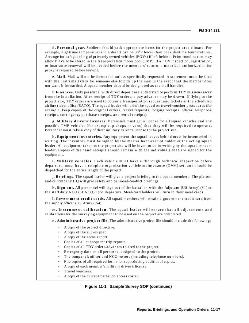
FM 3-34.331
d. Personal gear. Soldiers should pack appropriate items for the project-area climate. Forexample, nighttime temperatures in a desert can be 30°F lower than peak daytime temperatures.Arrange for safeguarding of privately owned vehicles (POVs) if left behind. Prior coordination mayallow POVs to be stored in the transportation motor pool (TMP). If a POV inspection, registration,or insurance renewal will be needed before the members’ return, a notarized authorization forproxy is required before leaving.
e. Mail. Mail will not be forwarded unless specifically requested. A statement must be filedwith the unit’s mail clerk for someone else to pick up the mail in the event that the member doesnot want it forwarded. A squad member should be designated as the mail handler.
f. Finances. Only personnel with direct deposit are authorized to perform TDY missions awayfrom the installation. After receipt of TDY orders, a pay advance may be drawn. If flying to theproject site, TDY orders are used to obtain a transportation request and tickets at the scheduledairline ticket office (SATO). The squad leader will brief the squad on travel-voucher procedures (forexample, keep copies of the original orders, travel requests, lodging receipts, official telephonereceipts, contingency purchase receipts, and rental receipts).
g. Military drivers’ licenses. Personnel must get a license for all squad vehicles and anypossible TMP vehicles (for example, pickups or vans) that they will be required to operate.Personnel must take a copy of their military driver’s license to the project site.
h. Equipment inventories. Any equipment the squad leaves behind must be inventoried inwriting. The inventory must be signed by the master hand-receipt holder or the acting squadleader. All equipment taken to the project site will be inventoried in writing by the squad or teamleader. Copies of the hand receipts should remain with the individuals that are signed for theequipment.
i. Military vehicles. Each vehicle must have a thorough technical inspection beforedeparture, must have a complete organization vehicle maintenance (OVM) set, and should bedispatched for the entire length of the project.
j. Briefings. The squad leader will give a project briefing to the squad members. The platoonand/or company HQ will give safety and personal-conduct briefings.
k. Sign out. All personnel will sign out of the battalion with the Adjutant (US Army) (S1) orthe staff duty NCO (SDNCO) upon departure. Meal-card holders will turn in their meal cards.
l. Government credit cards. All squad members will obtain a government credit card fromthe supply officer (US Army) (S4).
m. Instrument calibration. The squad leader will ensure that all adjustments andcalibrations for the surveying equipment to be used on the project are completed.
n. Administrative project file. The administrative project file should include the following:
• A copy of the project directive.• A copy of the survey plan.• A copy of the recon report.• Copies of all subsequent trip reports.• Copies of all TDY orders/advances related to the project.• Emergency data on all personnel assigned to the project.• The company’s officer and NCO rosters (including telephone numbers).• File copies of all required forms for reproducing additional copies.• A copy of each member’s military driver’s license.• Travel vouchers.• A copy of the current battalion access roster.
Figure 11-1. Sample Survey SOP (continued)
Reports, Briefings, and Operation Orders 11-17

FM 3-34.331
o. GS equipment and supplies. The following GS equipment and supplies should beincluded:
• Office supplies.• Survey and other support forms.• A first-aid kit.• Drawing, chart, and printer paper.• Calculators, paper, and batteries.• Counseling statements.• Official mailing envelopes.• Weekly-report forms.
p. Reference materials. The following reference materials should be included:
• Maps and trig lists.• Soldier training publications (STPs) and common training task (CTT) manuals.• Job books.• Survey manuals.• The company’s survey SOP.• TMs and manufacturers’ manuals.
q. Training. Training should be completed or rescheduled as necessary. Consider thefollowing training requirements:
• Annual training requirements (mission), to include weapons qualification and the Armyphysical fitness test (APFT).
• Annual training requirements (personal knowledge), to include CTT packets andscheduled training for the TDY period.
• Weight-control program.• POV training (to include registration and operator’s license).• Defensive-driving training.• Off-duty classes.
r. Family members. Personnel must get a power of attorney (if needed) and makearrangements for nonlicensed dependents (such as commissary, hospital, and shopping privileges).
14. ADVANCE PARTY
a. Generally, the squad leader and one or two squad members will depart first. The assistantsquad leader will complete the final administrative preparations with the remaining squadmembers.
b. The squad leader will inspect and sign for quarters and administrative space at the projectsite. Telephonic communications with the company at the home site should be established uponarrival and equipment should be secured. If communication with the home site is required afterduty hours, contact will be made with platoon HQ personnel at home or, as a last resort, with theSDNCO.
c. All POCs from the initial recon should be contacted. Additionally, the military or local policeshould be informed of mission requirements, AOs, vehicle types, and bumper/license numbers.
d. Further detailed recon/station recovery and verification should begin immediately and thefinal project design completed. Coordinate access for keys, escorts, and range-control data fromlocal surveyors or the local courthouse. A successful advance party will allow the squad to beginwork as soon as they arrive at the project site.
Figure 11-1. Sample Survey SOP (continued)
11-18 Reports, Briefings, and Operation Orders

FM 3-34.331
15. SQUAD MOVEMENT TO THE PROJECT
a. The squad leader or the assistant squad leader will conduct the movement to the project. Allvehicles will move as a group under the NCOIC’s control. If the project site is 450 miles or lessaway, the movement time will be one day. At distances greater than 450 miles, the movement ratewill be approximately 300 miles per day. All overnight lodging will be at one location if possible,and all equipment will be secured.
b. Obtain fuel at service stations that accept government credit cards. Use self-service pumpswhen possible.
c. Each day, the platoon HQ or the SDNCO will be given the location and telephone number ofthe overnight lodging. They will also be notified upon arrival at the project site.
d. If movement is by commercial air, ensure that all baggage claim checks are safeguardeduntil all equipment is received at the final destination. If movement is by military aircraft, makeevery attempt to move the equipment with the personnel. If equipment must be movedindependently, the equipment will be submitted with a “priority, no-bump” statement. At least oneperson will observe the physical loading of the survey equipment onto the aircraft. Copies of allmovement documents will be retained until the equipment is received after movement. At aminimum, obtain and document the—
• Type and model of the aircraft.• Tail number of the aircraft.• Mission number.• Number of the transportation-control-and-movement document (TCMD).• Date and time of departure.• Route of the aircraft (including any intermediate stops before the survey equipment is
to be unloaded).
16. PROJECT EXECUTION
a. Fieldwork. The squad leader is responsible for daily checks of fieldwork and computations.All recordings and computations should be in black ink, double-checked, and initialed to indicatethat the checks have been performed.
b. Maintenance. Daily maintenance on each vehicle and weekly preventive-maintenancechecks and services (PMCS) on all survey equipment should be performed. Report immediately toplatoon HQ each time the equipment-readiness status changes. All accidents must be reported tothe company commander within 24 hours. Accident reports and statements from all concernedparties will be prepared immediately and forwarded to the company commander.
c. Safety. All guidelines set forth in the unit’s safety SOP must be followed.
d. Inventories. Those items used in the field survey and all sensitive items of equipment (forexample, survey instruments, binoculars, compasses, and OVM) must be inventoried daily.Inventory weekly all hand-receipted equipment, and report any damaged, lost, or inoperationalequipment to the platoon HQ within 24 hours.
e. Training. The squad leader will determine the type and schedule of physical training. Thephysical training should meet current minimum standards. CTT and soldier’s manuals (SMs)should be taken to the project because training in these skills can be conducted during inclementweather.
f. Progress reports. Weekly progress reports will be submitted to the platoon HQ. Theformat shown at Annex D should be used to record vehicle mileage, fuel used, work hoursexpended, and the percent of the project completed.
g. Daily log. The squad leader will keep a written daily log of the progress, activities, andproblems that relate directly to the mission. All other occurrences (such as personnel insubordinatebehavior) will be recorded. The squad leader will be prepared at all times to present an informalprogress briefing to any visitors or inspectors.
Figure 11-1. Sample Survey SOP (continued)
Reports, Briefings, and Operation Orders 11-19

FM 3-34.331
17. ON-SITE EDIT
a. The squad is responsible for conducting an on-site edit during the last phase of the project(if possible). This edit will include, but is not limited to, checking—
• Computations. Math computations and procedures must be done correctly (to includeall headings and signatures).
• Field sheets/books. Field notes should be checked and have headings.• Station descriptions. Station descriptions must include a completed sketch,
appropriate reference features, and field-note checks. Grammar and paragraphsequence should be checked.
• Airfield drawings. Airfield drawings must be complete, accurately plotted, and fieldchecked.
b. All corrections and notations made by edit personnel will be in red ink. All pages checkedwill include the editor’s initials in red ink. Notes and lists should be free of any glaring or repetitiveerrors.
18. SQUAD MOVEMENT FROM THE PROJECT
a. After all field observations and computations are completed, the squad will clear the projectsite and return to the home installation. The squad leader will ensure that—
• Borrowed equipment is turned in.• The lodging area is cleaned.• Equipment is inventoried.• Preoperational vehicle checks are conducted.• All outstanding bills are paid.• All vehicles are properly dispatched.
b. The customer will not be provided a copy of the unedited data unless so directed by theplatoon/company HQ. When required to leave a copy with the customer, ensure that a statement isattached indicating that the data provided is preliminary and unadjusted.
c. Movement from the project will be conducted the same as movement to the project. Theplatoon HQ will be contacted before departure from the project site.
19. SQUAD RECOVERY. Upon return to the home installation, the following will beaccomplished:
• A platoon representative will meet the returning squad with any instructions.• Members will sign in at the S1 or the SDNCO.• Members will sign for keys and inventory their wall lockers.• Vehicles will be topped off, cleaned, technically inspected, and secured at TMP.• TOE equipment will be cleaned, inventoried, inspected, and secured. Any required
maintenance will be scheduled.• Finance vouchers will be completed, inspected at the platoon HQ, and filed with the FAO
for payment.• The platoon HQ will be briefed on the project’s status.• Each person’s final finance voucher will be forwarded through the platoon HQ to the
company operations section when received.• Time for personal affairs and missed training will be scheduled.
20. EDIT AT HQ. Upon return from the project, the squad leader will submit a completed surveypacket to the platoon HQ. The platoon HQ will check all final computations, drafting, andrecovery-card preparation. An end-of-project report (Annex E) (Figure 11-9, page 11-30) will besubmitted by the squad leader to the platoon HQ within three working days after the surveyproject is completed. A copy of the report should be included in the survey packet. The surveypacket should contain (in the following order) this information:
• The end-of-project report.• A detailed narrative (packet introduction) explaining the contents of the packet.
Figure 11-1. Sample Survey SOP (continued)
11-20 Reports, Briefings, and Operation Orders

FM 3-34.331
• A sketch or an overlay of all the work done.• An index.• Tabulated data and DA Forms 1959.• Check-angle, GPS, distance, level, and starting-inverse computations.• All level lines, traverses, and GPS data in sequence (main-control extension, connecting
control, and side or loop extensions).■ Level lines will contain (in order) a sketch of the level line, a DA Form 1942, and field
notes.■ Traverses will contain (in order) a sketch of the traverse, final position computations
(DA Forms 1923 and 1940), the final inverse position, elevation computations,abstracts, distance-measurement/reduction field sheets, horizontal-direction fieldnotes, vertical-angle/ZD field notes, and intersection/side-shot notes.
■ GPS data will contain a sketch of the GPS positions, printed position computations anddatum transformations, and backup disks containing all recorded data.
21. PLATOON REVIEW
a. The platoon will review the end-of-project report and make a file of all pertinent records,vouchers, forms, reports, and copies of the final product. The platoon will make appropriate awardrecommendations and ensure that all members’ finance transactions (for example, meal cards,separate rations, and basic allowance for quarters [BAQ]) are followed through to completion.
b. Upon completion of the platoon review, a first endorsement to the end-of-project report willbe prepared by the platoon and forwarded with the report and final project packet to the companyoperations section. The endorsement will identify any additional work hours expended during theedit and review, inspection results, and any other pertinent data.
22. COMPANY OPERATIONS-SECTION FINAL REVIEW. The company operations sectionwill review the final project packet for accuracy and completeness. A file copy will be made and anypertinent data will be stored in the SIC. The project packet will be forwarded (with a letter oftransmittal) to the battalion S3. Additionally, a second endorsement to the end-of-project reportwill be prepared and forwarded to the battalion S3. This endorsement will contain any additionalwork hours expended during the edit and review and inspection and all final project data. Copies ofthe end-of-project report (with all endorsements and enclosures) will be forwarded to the platoonHQ and the battalion S3 for information and filing. A file copy will also be kept in the companyoperations section.
Figure 11-1. Sample Survey SOP (continued)
Reports, Briefings, and Operation Orders 11-21

FM 3-34.331
DEPARTMENT OF THE ARMYEngineer CompanyEngineer Battalion (Topography) (Army)Fort Anywhere, State, and Zip
AFFA-TA-S 03 February XXXX
CommanderEngineer CompanyAttention: OperationsFort Anywhere, State, and Zip
Reference: Project directive number, date, FAA Airfield Obstruction Survey.
SUBJECT: ISVT Report (Fort Bliss, Biggs Army Airfield [AAF], Texas, 28 - 31 January XXXX)
1. PERSONNEL
a. List all POCs at the project site.
b. List any other POCs involved with the project.
2. OBJECTIVES
a. Determine the scope of the work to be performed.
b. Make a thorough recon of the areas to be surveyed. Locate existing survey control.
c. Complete a liaison for all types of support requirements ranging from lodging to vehiclemaintenance.
3. MISSION. The Survey Section, 99th Engineer Company, will dispatch a survey team of eightmembers to Fort Bliss, Texas, on or about 19 February XXXX, after receipt of project funding. Theywill conduct a complete survey of all NAVAIDs and airfield obstructions according to specificationsestablished by the US Army Air Traffic Control (ATC) Activity, Aeronautical Services Agency,Cameron Station, Alexandria, Virginia, 22304-5050. If time and funding permit, the team willrevalidate the aging compass rose located on Biggs AAF.
4. DISCUSSION
a. Location. Biggs AAF is located adjacent to Fort Bliss, Texas, and El Paso InternationalAirport.
b. Environmental factors. The terrain is basically flat, with the airfield being located on ahigh desert plateau. The Franklin Mountains are located about 4 miles west of the airfield, and theHueco Mountains are located about 15 miles to the east. Vegetation is sparse and is limited toscrub brush. Normal daily temperatures for this time of year are 40ºF to 50ºF during the day and20ºF to 30ºF at night. Precipitation is minimal throughout the year.
c. Medical facilities. Emergency medical treatment is available 24 hours a day at theWilliam Beaumont Army Medical Center. Routine treatment may be accomplished at theconsolidated troop medical clinic located in Building 2496. Dental care will be provided (foremergencies only) at the dental clinic located in Building 2699.
Figure 11-2. Sample Annex A (ISVT Report)
11-22 Reports, Briefings, and Operation Orders

FM 3-34.331
d. Shopping facilities. Complete commissary and post exchange (PX) facilities are availableon Fort Bliss. Additionally, small branch exchanges are located throughout the post and on BiggsAAF. Both facilities accept checks, and the PX will cash personal checks for up to $100 per day.Additionally, the PX will accept certain specified credit cards.
e. Vehicle maintenance. Fort Bliss TMP is unable to support our vehicle requirements. Wewill rent two sedans and one pickup truck from the Bogus Rental Car Company, El Paso, Texas.Fuel will be procured through TMP with DPW reimbursing TMP for the fuel used.
f. Lodging and office space. As of this date, the only lodging available on Fort Bliss isthrough the bachelor enlisted quarters (BEQ). The lodging office is located in Building 504A. Officeand equipment-storage space is available on Biggs AAF. The POC is the airfield operations office.
g. Dining facilities. The use of government mess is adverse to the timely completion of themission on Fort Bliss. Access to the project site is controlled by the airfield operations office, andthe hours of work are adjusted according to flight operations. It would cause undo delay to haltsurvey operations to meet the scheduled meal times of a dining facility. It is strongly recommendedthat all personnel be placed on per diem. There are numerous restaurants and fast-foodestablishments in the Fort Bliss and El Paso area. There is also a food concession next to the PX.
h. Cost estimates. A cost-estimate work sheet is at Enclosure 1 (Figure 11-3, page 11-24) anda cost-estimate memorandum is at Enclosure 2 (Figure 11-4, page 11-25). Cost estimates shouldinclude the following:
• Parameters—■ Advance party.■ Remainder of crew.■ Command visitors.■ Rental cars.
• Actual costs—■ Airfare.■ Lodging.■ Per diem.■ Transportation to, on, and from the project site.■ Shipment of equipment (identify the shipping company).■ Contingency fund.
• Total estimated cost.
5. TECHNICAL INFORMATION (INCLUDE IF APPLICABLE)
6. RECOMMENDATION AND CONCLUSION. The project should be accepted by this unit. Itwill provide training in the following STP/MTP tasks:
a. Task number 051-260-1122 (Set Up Survey Target).
b. Task number xxx-xxx-xxxx (task title).
JOHN DOESergeant First Class (SFC), US ArmySurvey-Section NCOIC
Enclosures
Figure 11-2. Sample Annex A (ISVT Report) (continued)
Reports, Briefings, and Operation Orders 11-23

FM 3-34.331
Figure 11-3. Sample Enclosure 1 to Annex A (Cost-Estimate Work Sheet)
Cost-Estimate Work Sheet
Parameters
Advance party: Depart ___28 May 1999 ____ (number of personnel _____ 3_____)
Return ___ 4 June 1999 ____ (number of personnel _____ 1 _____)
Return ___ 7 July 1999 _____ (number of personnel ______2_____)
Remainder of crew: Depart ____ 2 June 1999____ (number of personnel _____9______)
Return ____ 7 July 1999_____ (number of personnel _____9______)
Command visitors: Depart _____22 June 1999___ (number of personnel _____2______)
Return _____24 June 1999___ (number of personnel _____2______)
Rental cars: ______________________________________________________________
______________________________________________________________
______________________________________________________________
______________________________________________________________
Actual costs
Airfare: Advance party
Crew
Visitors
_3__ persons x $_899.00__
_9__ persons x $_899.00__
_2__ persons x $_899.00__
= $ 2,667.00
= $ 8,001.00
= $ 1,778.00
Total = $ 12,446.00
Lodging: Advance party
Advance party
Crew
Visitors
__2_ persons x __40_ days x$25.00
__1_ persons x __6__ days x$25.00
_9__ persons x __36_ days x$25.00
_2__ persons x __2__ days x$25.00
= $ 2,000.00
= $ 150.00
= $ 8,100.00
= $ 100.00
Total = $ 22,796.00
Per diem ($49.50 per day) = $ 22,176.00
Total = $ 44.972.00
Transportation to the site (provided by local personnel) = $ 0.00
Shipment of equipment (identify the company) = $ 3,100.00
Contingency fund = $ 3,000.00
Total cost = $ 51,072.00
11-24 Reports, Briefings, and Operation Orders

FM 3-34.331
DEPARTMENT OF THE ARMYEngineer CompanyEngineer Battalion (Topographic)Fort Anywhere, State, and Zip
(office symbol) 31 January XXXX
CommanderUnited States Army Air-Defense Center and Fort Bliss (USAADCENFB)Attention: ATZC-DPW-PFort Bliss, Texas 79916-6104
SUBJECT: Biggs AAF Survey Cost Estimate
1. After performing a thorough recon for this project, I estimate the cost for this project to be$51,000.00. This cost estimate reflects the fact that no vehicle support or free lodging areavailable from Fort Bliss.
2. This cost estimate does not reflect the amount that DPW will need to reimburse the FortBliss TMP for about 200 gallons of gas. This fuel will be needed for use by the three rentalvehicles to be used on this project.
3. A funding request for the amount of the cost estimate should be prepared and forwarded to:Commander, Engineer Battalion (Topographic), Attention: AFFA-TA-PCS, Fort Anywhere,State, and Zip. Request this action be expedited to allow the project to begin on19 February XXXX.
JOHN DOESFC, US ArmySurvey-Section NCOIC
Figure 11-4. Sample Enclosure 2 to Annex A (Cost-Estimate Memorandum)
Reports, Briefings, and Operation Orders 11-25

FM 3-34.331
Engineer Battalion (Topographic)Fort Anywhere, State, and Zip
References:a. Letter, dated 17 May XXXX, SUBJECT: Engineering Surveys of AAFsb. Letter, dated 29 May XXXX, SUBJECT: Engineering Surveys of AAFsTime zone used throughout this order: ROMEO
SUBJECT: TECHOPORD (Fort Bliss)
1. SITUATION
a. Enemy forces. None.
b. Friendly forces. DPW, Fort Bliss, Texas, Engineer Battalion (Topographic) (Airborne)with subordinate units (HHC and Engineer Company [Topographic]).
c. Attachments and detachments. None.
2. MISSION. The engineer company (topographic) will perform a NAVAID/obstruction surveyof Biggs AAF, which is adjacent to Fort Bliss, Texas.
3. EXECUTION
a. Concept of operation. The engineer company (topographic) will coordinate, schedule,and perform survey operations to accomplish the above mission not later than 30 April XXXX.The S3 will monitor project progress and coordinate external requirements upon request.
b. Coordinating instructions. Direct coordination with the following POC isauthorized: First Lieutenant (1LT) Gibson, Master Planners Office, DPW, Fort Bliss, Texas,555-555-5555.
4. SERVICE SUPPORT
a. Unit equipment and supplies will be used. Rental vehicles are authorized ifeconomically feasible.
b. Support request(s) will be submitted to this HQ, Attention: AFFA-TA-OP, as needed.
5. COMMAND AND SIGNAL
a. Command. Refer to the battalion’s SOP and complete the following reports.
(1) Submit a recon report within 30 days of receipt of this OPORD to the S3.
(2) Report the project’s status weekly to the S3 not later than 1200 hours each Friday.
(3) Submit an end-of-project report to the S3 within 15 days after completion of theproject.
b. Signal. None.
WILLIAM SMITHLieutenant Colonel (LTC), Engineer (EN)Commanding
Figure 11-5. Sample Annex B (TECHOPORD)
11-26 Reports, Briefings, and Operation Orders

FM 3-34.331
FRAGO # 99-2009-1
References:a. Technical Operations Work Order # 99-2009b. FM 3-34.331c. STP 5-82D14-SM-Trainer’s Guide (TG), Task # 051-260-XXXXTime Zone Used Throughout the Order: ROMEO
SUBJECT: FRAGO (Fort Bliss)
1. SITUATION
a. Friendly forces. Engineer battalion (topographic).
b. Enemy forces. None.
c. Assumptions. This unit may be tasked to perform high-order survey work in the nearfuture. Personnel should become familiar with the computations associated with this type ofwork.
2. MISSION. Each squad within the survey section, engineer company, has been tasked tocompute the geodetic azimuth from the north and the geodetic distance for each set of knowncoordinates to be used during the survey.
3. EXECUTION
a. Concept of operations.
(1) Transcribe the positions for each set of known coordinates onto DA Form 1923.
(2) Compute the geodetic azimuth from the north and the geodetic distance for eachset of coordinates.
(3) Compute the distance to 0.001 meter and the azimuth to 0.01″.
(4) Comply with third-order, Class I traverse specifications.
(5) Maximize the use of personnel that are unfamiliar with this computation fortraining purposes.
(6) Submit progress reports (to include the work hours expended and a by-name list ofthe personnel working on computations) by 1100 hours each Friday until the completion of theproject.
(7) Submit the completed data to the survey-section NCOIC by the close of business27 February XXXX.
b. Coordinating instructions. Calculators and reference materials are available fromSFC Doe. All technical questions/problems should be directed to SFC Doe.
4. ADMINISTRATION AND LOGISTICS. The only available resources are those containedwithin the survey section.
5. COMMAND AND SIGNAL
a. Command. Squad leaders are responsible to ensure that all required data and reportsreach the survey-section NCOIC as required.
b. Signal. None.
JOHN DOESFC, US ArmySurvey-Section NCOIC
Figure 11-6. Sample Annex C (FRAGO)
Reports, Briefings, and Operation Orders 11-27

FM 3-34.331
26 February XXXX
MEMORANDUM FOR SEE DISTRIBUTION
FROM Commander, Engineer Company (Topographic), Fort Anywhere, State, and Zip
SUBJECT: FA-TA-S Survey Project, Percentage of Completion
1. To standardize company operating procedures, projects will be reported using a survey-projecttimeline that lists the percentage of completion for each project task.
2. The project’s status is due to the company operations section each Friday by 1000 hours.Request immediate attention be given to this suspense.
3. A sample survey-project timeline is enclosed.
4. The field-survey percentage-of-project-completion timeline is broken down for each project taskand is reported as follows:
• Traverse for extension of control.• Level line for control extension or cross sections/profiles.• GPS point positioning.• Airfield obstructions or NAVAIDs.• Drafting.
MARY DOECaptain (CPT), ENCommanding
Enclosure
Figure 11-7. Sample Annex D (Percentage-of-Project-Completion Report)
11-28 Reports, Briefings, and Operation Orders

FM 3-34.331
Figure 11-8. Sample Survey-Project Timeline
TASK SURVEY-PROJECT TIMELINE (DAYS)
1 2 3 4 5 6 7 8 9 10 11 12 13 14 15 16 17 18 19 20 21 22 23 24 25 26 27 28
Travel andadministration
88/5
0 0 8 8/5 0
Monumentation 8 0 0 0
Level line 1 1 1 1 0 0 0
GPS-datacollection
4 4 4 0 0 0
Runway profiles 0 1 0 0
Obstructions/side shots
0 2 2 2 2 2 2 0 2 2 0
Computations 0 6 6 6 6 6 6 0 6 6 6 6 0
Checks andreobservations
0 4 1 0 2 2 0
Drafting* 6 6 6 6 6 6 6 6 6
LEGEND:0 = Day off1 = Level
2 = AISI3 = Transit
4 = GPS5 = Vehicles
6 = PC8 = Personnel
*To be completed at the home station.
Reports, Briefings, and Operation Orders 11-29
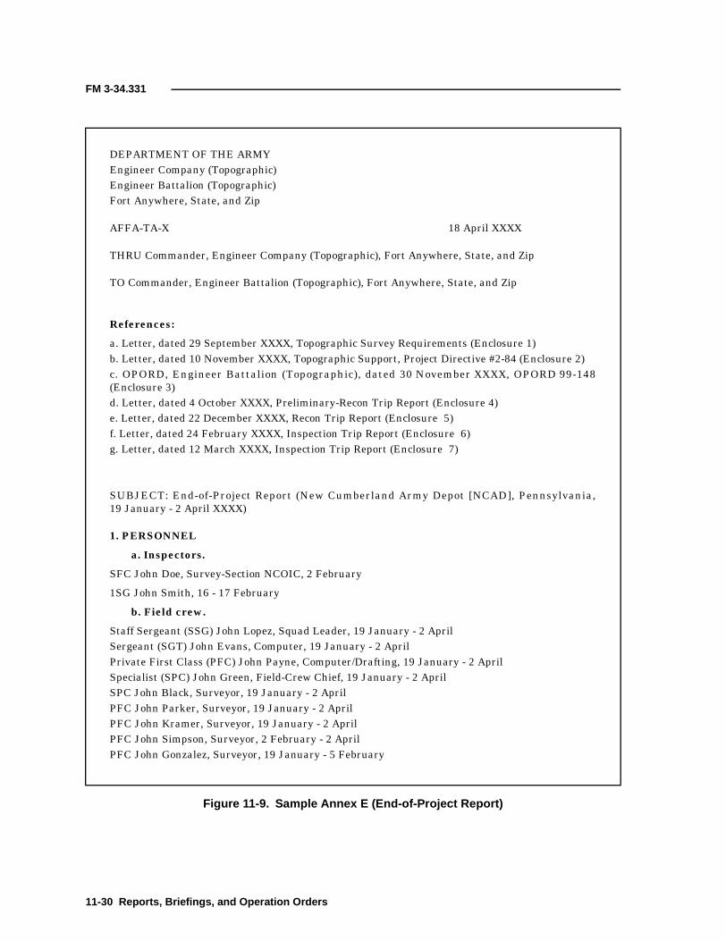
FM 3-34.331
DEPARTMENT OF THE ARMYEngineer Company (Topographic)Engineer Battalion (Topographic)Fort Anywhere, State, and Zip
AFFA-TA-X 18 April XXXX
THRU Commander, Engineer Company (Topographic), Fort Anywhere, State, and Zip
TO Commander, Engineer Battalion (Topographic), Fort Anywhere, State, and Zip
References:
a. Letter, dated 29 September XXXX, Topographic Survey Requirements (Enclosure 1)b. Letter, dated 10 November XXXX, Topographic Support, Project Directive #2-84 (Enclosure 2)c. OPORD, Engineer Battalion (Topographic), dated 30 November XXXX, OPORD 99-148(Enclosure 3)d. Letter, dated 4 October XXXX, Preliminary-Recon Trip Report (Enclosure 4)e. Letter, dated 22 December XXXX, Recon Trip Report (Enclosure 5)f. Letter, dated 24 February XXXX, Inspection Trip Report (Enclosure 6)g. Letter, dated 12 March XXXX, Inspection Trip Report (Enclosure 7)
SUBJECT: End-of-Project Report (New Cumberland Army Depot [NCAD], Pennsylvania,19 January - 2 April XXXX)
1. PERSONNEL
a. Inspectors.
SFC John Doe, Survey-Section NCOIC, 2 February
1SG John Smith, 16 - 17 February
b. Field crew.
Staff Sergeant (SSG) John Lopez, Squad Leader, 19 January - 2 AprilSergeant (SGT) John Evans, Computer, 19 January - 2 AprilPrivate First Class (PFC) John Payne, Computer/Drafting, 19 January - 2 AprilSpecialist (SPC) John Green, Field-Crew Chief, 19 January - 2 AprilSPC John Black, Surveyor, 19 January - 2 AprilPFC John Parker, Surveyor, 19 January - 2 AprilPFC John Kramer, Surveyor, 19 January - 2 AprilPFC John Simpson, Surveyor, 2 February - 2 AprilPFC John Gonzalez, Surveyor, 19 January - 5 February
Figure 11-9. Sample Annex E (End-of-Project Report)
11-30 Reports, Briefings, and Operation Orders

FM 3-34.331
2. REQUIREMENTS
a. The original requirements for the project were—
• To perform a verification survey of the entire boundary. The missing corners were to bemonumented by DPW, facilities engineering division (FED).
• To apply third-order elevations on the boundary monuments.• To develop topographic maps of the two areas where Buildings 87 and 92 would be
relocated.
b. After the final recon was completed, the requirements had been changed to—
• Perform a verification survey of the entire boundary. The missing corners were to bemonumented by the survey crew with monuments premade by DPW, FED.
• Apply third-order elevations on the boundary monuments.• Provide a drawing of the base boundary and station descriptions for each corner and
BM (the development of topographic maps was no longer necessary).
c. As the project neared its end and the monuments for the boundary corners were still notmade, the requirements for elevations on each boundary monument changed to establishing BMsnear the boundary corners (for example, nails in headwalls) and on as many boundary monumentsas time would permit. All other requirements remained the same as stated above.
3. METHODS. The mission was broken down into five main areas—recon, traversing, locatingcorners and placing monuments, leveling, and computing and drafting.
a. Recon. The recon was conducted about one month in advance of beginning the fieldwork. Itconsisted mainly of a deed search at the courthouse, requests for additional information fromadjoining landowners (for example, the Pennsylvania Turnpike Authority), an on-ground searchfor existing boundary corners and starting control, and logistical-support arrangements. Thisphase of the operation resulted in a reciprocal request from the Pennsylvania Turnpike Authorityfor two copies of the final drawings.
b. Traversing. All traverse work was performed using third-order, Class I procedures. Intotal, there were seven traverses, one of which was the main-control traverse. It contained 25stations and was run from Station Alpha (a first-order horizontal-control point) through boundarycorners number 4, 5, and 6 and Stations T-4 and T-5 and closed on Station Bravo (a second-orderpoint). This established a common coordinate system for the existing boundary corners. The othertraverses were used to place control near the location where the remaining boundary cornersshould have been. The azimuths were checked and verified by performing astronomic-azimuthobservations to third-order specifications at Station Alpha and at Stations T-4 and T-5. The main-control traverse had a position closure of 1:17,000, and the poorest closure obtained on any of theother six traverses was 1:5,000.
c. Locating corners and placing monuments. The lost/destroyed boundary corners wererecovered or replaced. Coordinates were computed for all boundary corners using the coordinatesestablished on boundary corners 4, 5, and 6 and the bearings and distances from the deeds.Inverses were computed from the traverse stations nearest the desired corner to that boundarycorner. The traverse station was occupied, the computed angle was turned, and the distance washorizontally taped, thus locating the corner in question. This point was then temporarily markedby either a piece of rebar, a railroad spike, or a nail, depending on the type of ground encountered.Plumbing benches were built over the temporary marks, the markers were removed, holes weredug, and the monuments were placed in their proper positions. After the dirt was tamped downand the plumb was checked, concrete collars were poured around the monuments to ensure thatthey would not move.
Figure 11-9. Sample Annex E (End-of-Project Report) (continued)
Reports, Briefings, and Operation Orders 11-31

FM 3-34.331
d. Leveling. The requirement for third-order elevations was met by running two third-orderlines. The first line started on BM 2 and ran around the perimeter of the southern half of the depotto BM 1. This line established 13 BMs, had an error of closure of 0.065 feet, and was 4.8 miles long.The second line started on BM 1 and ran around the perimeter of the northern half of the depotto Station T-4. This line established the elevation on seven points, had an error of closure of0.003 feet, and was 1.7 miles long.
e. Computing and drafting. Computing for this project was an ongoing endeavor from thetime of the final recon until two weeks after the end of the project. This was due to the vast numberof deeds for the land surrounding and now comprising the NCAD, and some of the final data wasneeded on site at the completion of the project. The drafting was accomplished in the last twoweeks of the project and consisted of three drawings. Copies of all drawings were provided to theFED and the Pennsylvania Turnpike Authority before departing the NCAD. Station descriptionswere an ongoing effort throughout the project.
5. EQUIPMENT. Two categories of equipment were used—organizational and borrowed.
a. Organizational. The organizational equipment included three M998 vehicles, twotheodolites (one military level and one infrared EDME), two Philadelphia rods, two T-2 target sets,one 50-meter tape measure, one 100-foot tape measure, one tape tension handle, one taping-pinset, and one programmable calculator.
b. Borrowed. The following items were borrowed from the NCAD, FED: three FM, hand-heldradios; one posthole digger; and one auger truck with operators. On two or three occasions whenthe vehicles were down, a carryall was borrowed from TMP.
6. ACHEIVEMENTS. Excellent training was gained by all personnel in traverse, leveling, taping,and monument-setting procedures. All personnel gained valuable experience at operating underextreme cold and wet conditions. SGT Evans and PFC Payne received valuable experience in alltypes of survey computations, to include curve layouts. SPC Green gained experience as a field-crew chief. The FED gained much needed field data that should prove useful any time projectsrequiring survey data are undertaken by their office. In addition, all personnel assigned to theproject and the engineer company (topographic) were awarded a certificate of appreciation fromthe depot commander.
7. TECHNICAL DIFFICULTIES. Most of the technical problems encountered were a directresult of the vast number of deeds involved. Many of those deeds listed magnetic bearings, whileothers used true bearings. Ordinarily this would have been no problem, but the catch was that outof all the deeds, only two specified what type of bearings they were listing. This left a large jigsawpuzzle with many variables. It became a matter of trial and error until the crew was finally able toget the boundary to close on itself. Another problem encountered was that one of the referencedrawings provided by FED had the numbers within a given distance transposed; that is, 1,307 feetwas really 1,370 feet. Additional problems were encountered when the only EDME went down andno replacement was available. The problems encountered in this area were due directly to a lack oftraining in taping procedures. This problem was resolved after about two days of intensive on-sitetraining.
8. ADMINISTRATIVE/OTHER PROBLEM AREAS. The largest single problem encounteredwas the vehicle-maintenance support. The support that was promised verbally by the NCAD, TMPnever developed. It is strongly recommended that a written agreement be established during therecon phase of all future projects. As for the problems encountered with the vehicles (for example,not starting or faulty exhaust systems), it is unclear how they could have gone through a completemaintenance check before departing for the project and still be in such a poor state of repair. Theonly other real problem encountered was the repeated adverse weather. In total, 13 work dayswere lost to snow, ice, rain, or fog.
Figure 11-9. Sample Annex E (End-of-Project Report) (continued)
11-32 Reports, Briefings, and Operation Orders

FM 3-34.331
9. SUMMARY. All in all, this was an excellent project. It fulfilled a vast amount of trainingrequirements in a wide variety of skills. Weaknesses in the equipment department became veryobvious. These weaknesses included a need for hand-held radios, medium- or long-range EDME,and four-wheel-drive vehicles.
JOHN LOPEZSSG, US ArmySquad Leader
Enclosures (not included with this sample)
Figure 11-9. Sample Annex E (End-of-Project Report) (continued)
Reports, Briefings, and Operation Orders 11-33

Appendix A
Mensural Conversion Charts
This appendix complies with current army directives, which state that themetric system will be incorporated into all new publications. Table A-1 is ametric conversion chart and Table A-2 shows conversion factors fortemperature, angles, and time.
Table A-1. Metric Conversion Chart
US Units Multiplied ByEquals
Metric Units Metric Units Multiplied ByEquals
US Units
Length
Inches 2.5400 Centimeters Centimeters 0.39370 Inches
Inches 25.4001 Millimeters Millimeters 0.03937 Inches
Feet 0.3048 Meters Meters 3.28080 Feet
Yards 0.9144 Meters Meters 1.09360 Yards
Miles 1.6093 Kilometers Kilometers 0.62140 Miles
Miles, Nautical 1.8532 Kilometers Kilometers 0.53960 Miles, Nautical
Area
Square miles 2.590Squarekilometers
Squarekilometers
0.38500 Square miles
Volume
Gallons 3.7854 Liters Liters 0.26420 Gallons
Mass (Weight)
Pounds 0.4536 Kilograms Kilograms 2.20460 Pounds
Table A-2. Temperature, Angle, and Time Conversion Chart
Units Multiplied By Equals Units Multiplied By Equals
Temperature
Degrees (F) - 32 0.5556 Degrees (C) Degrees (C) + 17.8 1.8000 Degrees (F)
Angle
Degrees(angular)
17.7778 Mils Mils 0.0562Degrees(angular)
Time
Seconds 0.001 Milliseconds Milliseconds 1,000 Seconds
Seconds 0.000000001 Nanoseconds Nanoseconds 1,000,000,000 Seconds
Mensural Conversion Charts A-1

Appendix B
Control-Survey Standards
This appendix is designed as a quick reference for platoon leaders. Itsummarizes the standards for control surveys that were discussed inChapters 6, 7, and 8.
DIFFERENTIAL LEVELING
B-1. Differential leveling is the conventional method of leveling for thepropagation of orthometric heights. Table B-1 and Tables B-2 and B-3,pages B-2 and B-3, show the overall standards and specifications fordifferential leveling.
Table B-1. Equipment Standards
RequirementOrder and Class
1st, I 1st, II 2nd, I 2nd, II 3rd
Level0.2 mm/kmspirit level
0.4 mm/kmelectronic barcode
Automatic levelwith parallel-platemicrometer or0.4 mm/kmelectronic barcode
0.8 mm/kmautomatic levelwith parallel-plate micrometeror electronic barcode
3-wireautomaticlevel
Staff construction Rigid invar Rigid invar Rigid invar Rigid invarWood or
metal
Staff graduation interval (mm) 5 5 5 or 10 5 or 10 10
Tripod construction Rigid Rigid Rigid Rigid Rigid
Bubble attached to staff Yes Yes Yes Yes Yes
Solid, portable change points NoNo (route ispremarked)
Yes Yes Yes
Umbrella for level Yes Yes Yes Yes No
Control-Survey Standards B-1
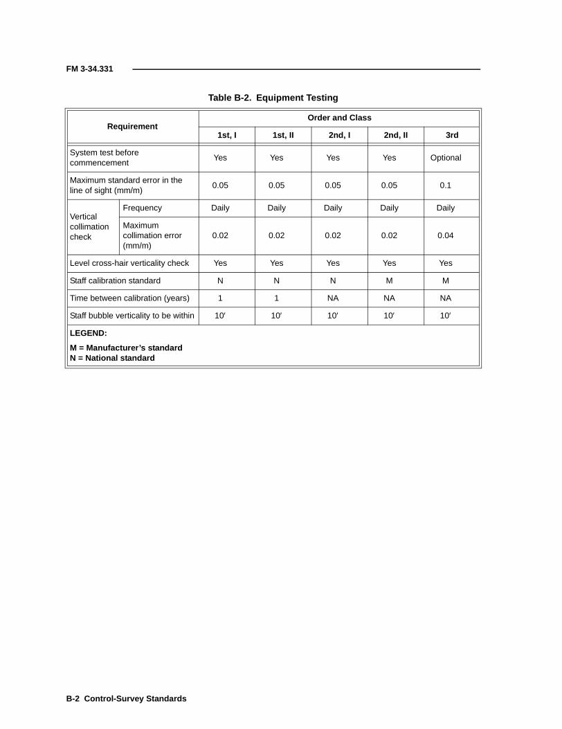
FM 3-34.331
Table B-2. Equipment Testing
RequirementOrder and Class
1st, I 1st, II 2nd, I 2nd, II 3rd
System test beforecommencement
Yes Yes Yes Yes Optional
Maximum standard error in theline of sight (mm/m)
0.05 0.05 0.05 0.05 0.1
Verticalcollimationcheck
Frequency Daily Daily Daily Daily Daily
Maximumcollimation error(mm/m)
0.02 0.02 0.02 0.02 0.04
Level cross-hair verticality check Yes Yes Yes Yes Yes
Staff calibration standard N N N M M
Time between calibration (years) 1 1 NA NA NA
Staff bubble verticality to be within 10′ 10′ 10′ 10′ 10′
LEGEND:
M = Manufacturer’s standardN = National standard
B-2 Control-Survey Standards

FM 3-34.331
HORIZONTAL-ANGLE MEASUREMENT
B-2. The observation requirements for horizontal-angle measurements areshown in Table B-4, page B-4. Adherence to these requirements should ensurethat the appropriate level of precision is achieved.
Table B-3. Observation and Reduction Requirements
RequirementOrder and Class
1st, I 1st, II 2nd, I 2nd, II 3rd
Instrument leveled by anunsystematic method
Yes Yes Yes Yes Yes
Leap-frog system of progressionused
Yes Yes Yes Yes Yes
Staff readings recorded to nearest(mm)
0.01 0.01 0.1 0.1 1
Temperature recordedStart,middle,finish
Start,middle,finish
At start and finish of each leveling run andat pronounced changes of temperature
Maximum length of sight (m) 50 60 60 70 90
Minimum ground clearance of lineof sight (m)
0.5 0.5 0.5 0.5 0.5
Backsight and foresight lengths tobe equal within (m)
2 5 5 10 10
Observation timeBefore1000 andafter 1400
Before1000 andafter 1400
Before 1000and after1400
Any time, providedatmospheric conditions allowpositive resolution of staffgraduation
Two-way leveling Yes Yes Yes Yes Yes
Even number of instrument setupsbetween BMs
Yes Yes Yes Yes Yes
Maximum section misclosure(mm)
Maximum loop misclosure (mm)
Minimum number of BMs 3 3 3 3 3
Double-leveled BM Yes Yes Yes Yes Yes
Maximum BM misclosure (mm)
Orthometric correction(collimation) to be applied
Yes Yes Yes Yes Yes
3 km 4 km 6 km 8 km 12 km
4 km 5 km 6 km 8 km 12 km
4 km 5 km 6 km 8 km 12 km
Control-Survey Standards B-3
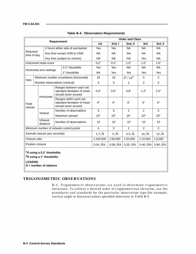
FM 3-34.331
TRIGONOMETRIC OBSERVATIONS
B-3. Trigonometric observations are used to determine trigonometricelevations. To achieve a desired order of trigonometrical elevation, use theprocedures and standards for the particular observation type (for example,vertical angle or distance) unless specified otherwise in Table B-5.
Table B-4. Observation Requirements
RequirementOrder and Class
1st 2nd, I 2nd, II 3rd 3rd, II
Requiredtime of day
2 hours either side of sunrise/set
Any time except 1200 to 1500
Any time (subject to checks)
Yes
NA
NA
Yes
NA
NA
NA
Yes
NA
NA
NA
Yes
NA
NA
NA
Instrument least count 0.2″ 0.2″ 1.0″ 1.0″ 1.0″
Horizontal zero settings0.2″ theodolite
1″ theodolite
Yes
NA
Yes
Yes
NA
Yes
NA
Yes
NA
Yes
SetsMinimum number of positions (horizontal)
Number observations (vertical)
16
3
16
3
81 / 122
2
4
2
2
2
Fieldchecks
Horizontal
Ranges between each set:standard deviation of meanshould never exceed
0.4″ 0.5″ 0.8″ 1.2″ 2.0″
Ranges within each set:standard deviation of meanshould never exceed
4″ 4″ 5″ 5″ 5″
VerticalNumber of observations
Maximum spread
3
10″
3
10″
2
10″
2
10″
2
20″Infrareddistance
Number of observations 10 10 10 10 10
Minimum number of network control points 4 3 2 2 2
Azimuth closure (arc seconds)
Closure ratio 1:100,000 1:50,000 1:20,000 1:10,000 1:5,000
Position closure
1If using a 0.2 ″ theodolite.2If using a 1 ″ theodolite.
LEGEND:N = number of stations
1.7 N 3 N 4.5 N 10 N 12 N
0.04 km 0.08 km 0.20 km 0.40 km 0.80 km
B-4 Control-Survey Standards

FM 3-34.331
GPS TECHNIQUES
B-4. There are two fundamental GPS techniques—relative and absolute-pointpositioning. The recommended practices for the GPS refer only to relativepositioning. Relative positioning requires two or more GPS receivers. The twofundamental types of GPS receivers are navigational and survey (or geodetic).The receivers are distinguished by the accuracy level and type ofmeasurements taken during surveys. Many receivers are capable of a numberof measurement types. Pseudorange and carrier-phase measurements are thetwo fundamental types of measurements made with GPS receivers.
RELATIVE-POSITIONING TECHNIQUES
B-5. Relative-positioning techniques can be divided into two main groups—static and kinematic. The fundamental difference is that kinematictechniques require maintaining lock throughout the survey after ambiguityresolution. These static and kinematic techniques employ carrier-phasemeasurements. Since a carrier-beat-phase measurement is the only type thatoffers a sufficient precision in geodetic positioning at third order and higher,the use of receivers that measure the carrier phase is mandatory. Static andkinematic techniques can be grouped as follows:
• The static group can be divided into the following techniques:■ Static (also referred to as classic static).■ Pseudokinematic (for example, intermittent static, pseudostatic,
or reoccupation kinematic).■ Rapid static (also referred to as quick static or fast static).
• The kinematic group can be divided into the following techniques:■ Stop-and-go kinematic (also referred to as intermittent kinematic
or semikinematic).■ Kinematic (also referred to as continuous kinematic).■ OTF/ (also referred to as ambiguity-resolution OTF).
B-6. A third group of relative-positioning techniques is based on pseudorangemeasurements. These techniques, either in postprocessed or real-time modes,
Table B-5. Observation Requirements
RequirementOrder
1st 2nd 3rd
Simultaneous reciprocal Yes Yes Optional
Nonsimultaneous reciprocal NA Yes Optional
One-way observation NA NA Yes
Observation time>16 km 1400 to 1600 1400 to 1600 1400 to 1600
<16 km 1000 to 1600 1000 to 1600 1000 to 1600
Number of sets 2 2 1
Number of pointings (per set) 6 6 6
Maximum range per set (in) 6 6 8
Meteorological observation Yes Yes Yes
Control-Survey Standards B-5

FM 3-34.331
are referred to as DGPS and are generally not used for precise control surveys.DGPS is used for accuracies of 2 to 5 meters. Precise DGPS is used foraccuracies of 1 meter or less.
B-7. By combining carrier-phase measurements with pseudorangemeasurements, it is possible to reach higher accuracies with DGPStechniques. While GPS measurements are receiver dependent, the selection ofobservation techniques is dependent on the precision required and thereduction process to be used.
NETWORK DESIGN AND GEOMETRY
B-8. When planning a GPS-S, the first step is to choose the appropriatetechnique for the precision required. Table B-6 provides a guide for whattechnique to use to achieve a particular order and class of survey. Table B-7provides references to the order and class of survey.
B-9. The location and distribution of points in a GPS-S do not dependsignificantly on factors such as network shape or intervisibility but rather onan optimum layout with sufficient redundancy for carrying out the intent ofthe survey. The intent of the network design should be to—
• Locate new points so that the line of sight between them is clear(when possible).
• Provide error control in the minimum-constraint solution (to enabledata validation) and analysis of the accuracy of the survey.
• Produce tie-offs for integrating the survey into previously establishedcontrol.
• Locate ties to points with existing orthometric heights.
B-10. Redundancies play an important role in fulfilling this intention. AllGPS-Ss must be connected to the existing control, the NGS, or the local projectto ensure survey integration, legal tractability, and quality assurance. Ifestablished control stations are not available in the vicinity of the survey,bring control to the appropriate accuracy by using GPS or conventionaltechniques. When selecting established stations to connect to, give preferenceto the highest order of the nearest, established permanent marks (or geodeticstations) that are easily accessible. Connection should be made to a minimumof three points with suitable MSL heights, preferably enclosing the survey,and a minimum of two points with established (horizontal) coordinates.Additional points are to be connected to obtain quality control, with preference
Table B-6. Positioning Techniques
TechniqueOrder and Class
1st 2nd, I 2nd, II 3rd
Static Yes Yes Yes Yes
Rapid static NA NA Yes Yes
Pseudokinematic NA NA NA Yes
Stop and go NA NA NA Yes
B-6 Control-Survey Standards

FM 3-34.331
given to coordinated marks that enclose the surveyed area and height pointsspaced throughout the area. A least-squares adjustment of the control surveymust be performed.
B-11. The planning of the observations should be such that the error budget issufficiently minimized. Consider the error budget of a double difference, whichconsists of error sources affecting measurements; error sources that dependupon the site and the type of instrumentation used; and error sourcesresulting from reduction, adjustment, and transformation.
B-12. Error sources that affect measurements are tropospheric refraction,ionospheric refraction, and orbit errors. The main error sources affected by thesite’s location and the instrumentation are centering and antenna-heightaccuracy, antenna-phase center variation, 3D differential-antenna offset,multipath and imaging errors, differential tropospheric delay, and differential
Table B-7. Positioning References
ReferenceOrder and Class
1st 2nd, I 2nd, II 3rd
Minimum station spacing1 (km) 5 1 0.5 0.2
Typical station spacing2 (km) 100-500 10-100 0.5-10 0.1-5
Independentoccupationsper station3
at least 3 times(% of total stations)
50% 40% 20% 10%
at least 2 times(% of total stations)
100% 100% 100% 100%
Minimum common satellites 4 satellites
Minimum PDOP required Less than 10 after resolution of ambiguities
Minimum satellite elevation 15°
Data rate Optional
Minimum observation period (static)4 120′ 60′ 45′ 30′
Minimum independent baselines ateach station
3 3 2 2
1The values relate to the use of conventional equipment and proprietary software.2Independent occupations per station may be back to back, but the antenna shouldbe reset for each occupation. Antenna heights are to be changed by at least 0.1 to0.2 meter unless set up on a pillar. The fully specified minimum-observation time
should be met with each occupation.3For example, for a second-order, Class II network, aim for 20 percent of stations tobe occupied at least three times and 100 percent of stations to be occupied at least
twice.4As a rule, 30 minutes as a definitive minimum plus about 2 minutes per kilometer.
Control-Survey Standards B-7
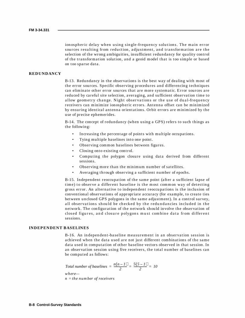
FM 3-34.331
ionospheric delay when using single-frequency solutions. The main errorsources resulting from reduction, adjustment, and transformation are theselection of the wrong ambiguities, insufficient redundancy for quality controlof the transformation solution, and a geoid model that is too simple or basedon too sparse data.
REDUNDANCY
B-13. Redundancy in the observations is the best way of dealing with most ofthe error sources. Specific observing procedures and differencing techniquescan eliminate other error sources that are more systematic. Error sources arereduced by careful site selection, averaging, and sufficient observation time toallow geometry change. Night observations or the use of dual-frequencyreceivers can minimize ionospheric errors. Antenna offset can be minimizedby ensuring identical antenna orientations. Orbit errors are minimized by theuse of precise ephemerides.
B-14. The concept of redundancy (when using a GPS) refers to such things asthe following:
• Increasing the percentage of points with multiple occupations.• Tying multiple baselines into one point.• Observing common baselines between figures.• Closing onto existing control.• Computing the polygon closure using data derived from different
sessions.• Observing more than the minimum number of satellites.• Averaging through observing a sufficient number of epochs.
B-15. Independent reoccupation of the same point (after a sufficient lapse oftime) to observe a different baseline is the most common way of detectinggross error. An alternative to independent reoccupations is the inclusion ofconventional observations of appropriate accuracy (for example, to create tiesbetween unclosed GPS polygons in the same adjustment). In a control survey,all observations should be checked by the redundancies included in thenetwork. The configuration of the network should involve the observation ofclosed figures, and closure polygons must combine data from differentsessions.
INDEPENDENT BASELINES
B-16. An independent-baseline measurement in an observation session isachieved when the data used are not just different combinations of the samedata used in computation of other baseline vectors observed in that session. Inan observation session using five receivers, the total number of baselines canbe computed as follows:
where—n = the number of receivers
Total number of baselinesn n 1–( )
2--------------------
5 5 1–( )2
-------------------- 10= = =
B-8 Control-Survey Standards
FM 3-34.331
B-17. However, only four (n - 1) of those baselines are independent. Theremainders (10 - 4 = 6) are formed from combinations of phase data used tocompute the independent baselines. The results from observations of the samebaseline made in two different sessions are independent. Generally,independent-baseline processors assume that there is no correlation betweenindependent vectors. Trivial baselines may be included in the adjustment tomake up for such a deficient statistical model. If the mathematical correlationbetween two or more simultaneously observed vectors in a session is notcarried in the variance-covariance matrix, the trivial baselines take on abracing function that simulates the effect of the proper correlation statistics.And, at the same time, introduce a false redundancy in the count of thedegrees of freedom. In this case, the number of trivial baselines in anadjustment should be subtracted from the number of redundancies before thevariance factor (variance of unit weight) is calculated. If this approach is notfollowed, trivial baselines will be excluded from the network altogether.
INCORPORATION OF GPS SURVEYS
B-18. To incorporate 3D GPS-Ss into local horizontal and vertical data(WGS-84 and MSL), the number, type, and distribution of control points towhich connections should be made must be considered. A determination ofwhich technique to use to derive orthometric heights from ellipsoidal heightsis necessary. The technique will influence the choice of well-placed strategicpoints with known orthometric heights that should be observed. Alternatively,orthometric heights can be brought to selected points in the GPS network.
B-19. For a small area (a few kilometers across) with a smooth geoid, solvingfor transformation parameters brings about a de facto surface fit (tilting theellipsoid so that it is parallel with the geoid). When a single value for thegeoid-spheroid separation is used at the orthometric-control points, it isassumed that the geoid is as smooth as the ellipsoid. For larger areas, choosebetween a geodetic-leveling, a geopotential model-based, a gravimetric, or ageometrically derived geoid.
B-20. The classification of GPS results (including height) is generallyexpressed using a linear propagation method, unless requirements specificallycall for height classification using differential leveling. In both cases, the classand the order are assigned separately for horizontal and vertical control.
SYSTEM TESTING
B-21. A system test is recommended to qualify equipment, techniques, anderror modeling for a particular accuracy. Evidence of a test may be requiredafter acquisition of new equipment or software, when trying new techniques,or as justification of a chosen method of error modeling. This evidenceserves—
• As a justification of observing and processing techniques.• To validate (under similar conditions) the same equipment, the
software, and the observation method.• To justify the error modeling.• As a justification of a multiplier used to increase the baseline-vector
variance-covariance matrix elements when these are unrealistic.• To validate data when combining results from different equipment
and software.
Control-Survey Standards B-9

FM 3-34.331
B-22. The total GPS process is comprised of the following four distinctcomponents:
• Satellites.• Receiver hardware.• Field procedures.• Software.
B-23. The following procedures describe a system test that considers all of thecomponents of the system and are designed to evaluate the performance ofmultiple receivers used in a differential mode. The field practices and systemtest have to reflect the particular observing strategies (for example, static,rapid static, or stop and go) that are employed on a project. The equipmentshould be operated according to the manufacturer’s specifications. The testconsists of a measurement of a small test network and the ongoing analysis ofproduction results.
Measurement of a Small Test Network
B-24. Control should be established on at least one baseline of the small testnetwork. This control consists of a measurement of—
(n + 1) stations and (n + 1) independent baselines
where–n = the number of receivers
B-25. The test network observed should be a polygon with station spacing notless than 50 meters and not more than 10 kilometers. The independentlyobserved baselines should be processed, baseline by baseline, to producedifferences in Cartesian coordinates in the satellite datum (∆X, ∆Y, and ∆Z)for each baseline. The summation of these differences, for any closed figure,will give a preliminary indication of the performance of the total GPS and isan initial, minimum field analysis. At the first opportunity, performance of amore rigorous approach is essential. The vectors and their associatedvariance-covariance matrices should be adjusted by the least-squares methodto obtain a more complete and comprehensive report on the equipment test. Ifthe results meet the manufacturer’s specification, then the manufacturer’sspecification can be adopted by the user as the measure of the precisionattainable with the system. If not, the user’s measurement system must bemodified to meet the manufacturer’s specification or the lower precision mustbe accepted.
Analysis of Production Results
B-26. The measurement of a GPS-S network involves the observation ofclosed figures. An analysis of the closure of all figures should be carried out toensure that each figure closes within the expected precision. Closure polygonsmust combine data from different sessions. A network adjustment is the mostefficient way to confirm agreement with established control at the requiredaccuracy.
B-10 Control-Survey Standards

FM 3-34.331
OBSERVATION REQUIREMENTS
B-27. The observation duration has to be long enough to resolve ambiguitiesand, depending upon the required accuracy, it also has to be long enough toaverage out multipath effects. This is especially true for second-order andhigher surveys. It is preferred to observe five or more satellites, although mosttechniques will work with a minimum of four satellites. The extra satellitesgive protection against loss of lock from one of the satellites and speeds up theambiguity-resolution process.
B-28. Equipment users should refer to the manufacturer’s specifications forDOP. DOP is an indicator of the geometrical strength of a four-or-moresatellite constellation as it applies to instantaneous point-position fixing.PDOP refers to the three position coordinates (while GDOP includes a termfor the clock offset). The lower the number, the better the geometry forachieving an accurate point position. Use caution in applying this parameteras an absolute acceptance or rejection criterion, particularly in relative GPSpositioning where longer observation periods remove most common biases.However, sufficiently changing geometry during a recording session assists inthe determination of ambiguities. Once the ambiguities are resolved, PDOPshould be kept low.
B-29. The minimum satellite elevation is 15ο. This requirement can bereduced to 10ο for third-order and lower surveys. It is necessary to ensure thatthe receiver-data rates are the same or a common integer factor of 60″, whichresults in sufficient common data to resolve ambiguities. Give specialattention when processing data collected from different types of receivers (5″,10″, 20″, or 30″ are typical). The time intervals must also be simultaneous.
B-30. When a reflective environment (horizontal, vertical, or skew) cannot beavoided, refrain from using both low satellites and satellites within half anhour either side of culmination for that site. Occupy the position (and theothers in the same session) for a minimum number of minutes that is equal to40 divided by the perpendicular distance to the suspected reflecting surface.This will generally increase the chance of capturing at least one full swing ofthe interference. When third-order and higher accuracies are required and asite with a reflective environment cannot be avoided, it is worthwhile toaverage longer observation times of the interference (virtually the equivalentof a static survey).
B-31. Manufacturers generally give a guide for the average time required toresolve ambiguities. When these times are shorter than the minimumobservation duration recommended above for reducing multipath, theobservation duration should be lengthened (following the above guide) if in areflective environment.
B-32. Field procedures are substantially the same as recommended abovewhen using static and kinematic techniques for requirements less stringentthan second order. This is because relative GPS can routinely deliver second-order accuracy. Refer to the manufacturer’s manual for any additionalrequirements. RTK carrier-phase techniques already impact on the first10 kilometers of second- and lower-order surveys. At this stage of the analysis,different criteria should be applied depending on the project requirements. Asummary of the various observational techniques follow.
Control-Survey Standards B-11

FM 3-34.331
Static
B-33. Static surveying uses two or more receivers that remain stationary for30 minutes or more, depending on the line length and the required accuracy.Carrier-phase observations are made, and to enhance the carrier-phaseambiguity resolution, the satellite geometry should be given time to change.Observations are made (with two or more receivers that have a common datarate) to four or more satellites with elevations above 15ο. An accuracy of 0.1 to10 ppm is possible, depending upon the quality of the data, the processing,and the length of the baseline vectors.
Rapid Static
B-34. Rapid-static surveying uses various combinations of observations (forexample, C/A-, P- or Y-code range data and L1 and L2 carrier-range data). Ifthe view of the sky is limited, rapid-static surveying depends on least-squaresambiguity estimation for a determination of the correct ambiguities. Thereliability is enhanced when data from six or more satellites are used andmultiple occupations are made at different sidereal times. Dual-frequencyreceivers are advantageous because they allow various data combinations (forexample, widelaning) in estimating a solution. Occupation times of 2′ to 10′ isrequired to obtain centimeter-level accuracy for vector lengths up to10 kilometers.
Stop-and-Go Kinematic
B-35. Stop-and-go-kinematic surveying involves alternately stopping andmoving of one receiver, with the main interest being in the stopped positions.This technique relies upon determining baselines, with a minimum amount ofdata, by resolving the carrier-phase ambiguities at the beginning andmaintaining lock throughout the survey.
B-36. In stop-and-go surveying, two receivers observe a predeterminedbaseline and perform an antenna swap. The antenna swap is used to obtainthe baseline in a matter of a few minutes. The process where carrier-phaseambiguities between satellites and receivers are resolved before the otherreceiver starts roving is called initialization.
B-37. The second receiver then starts roving, staying stationary over pointsfor a few seconds to a few minutes. Constant satellite lock should bemaintained on at least four satellites and is the major factor with thistechnique, which makes it suitable for open terrain only. An accuracy of 20 to30 millimeters is possible, and accuracies of 1 to 10 ppm have been quoted.Good geometry and the observation of a minimum of a dozen epochs at eachsurvey point are important for this technique. The short occupation times givea rapid drop-off in height accuracy. Good planning is advantageous, and theoccasional occupation of a known point is necessary in case the geometrydeteriorates or a cycle slip occurs before the survey can be closed. RTKmethods fit this category, because RTK presupposes access to actual phaseobservations at a site with known coordinates, to produce a double-difference,ambiguity-fixed solution in real time.
B-12 Control-Survey Standards

FM 3-34.331
Kinematic
B-38. Kinematic surveying proceeds as in stop-and-go-kinematic surveyingbut without stopping. Vectors are created that are associated with singleepochs in time.
Pseudokinematic
B-39. Pseudokinematic surveying does not depend on continuous lock of therover(s) while traveling but requires continuous lock while stationary. Thesame point is reoccupied after 1 to 2 hours by the same receiver and again forabout 3′ to 10′. This creates a situation of having one deliberate cycle slipdividing the data. This paired observation is defined as a single stationobservation. Obtaining the change in satellite geometry enhances theambiguity resolution. A constant antenna height allows the two data sets torepresent measurements to the same physical point in space.
B-40. Accuracies can reach 20 to 30 millimeters depending upon satelliteavailability and PDOP. Accuracies of 2 to 20 ppm have been quoted. Single- ordual-frequency carrier-phase receivers can be used. Dual-frequencyobservations, although not necessary, enhance the determination of theambiguities. For practical purposes, maximum vector lengths are about15 kilometers.
B-41. While not as productive as the stop-and-go-kinematic technique, thepseudokinematic technique does not rely on maintaining satellite lock. Thepseudokinematic technique is much more practical in areas where trees,buildings, tunnels, overpasses, or other obstructions are likely to interrupt thesignal or where interstation access is slow.
OTF/RTK Kinematic
B-42. OTF/RTK surveying uses a continuous kinematic technique, which isideal when the roving receiver cannot stop for an initialization. OTF/RTK doesnot need initialization; it performs auto-reverse processing as soon as theambiguities are resolved. Contrary to the definition of kinematic techniques,OTF/RTK does not need initialization at the start. A sufficient number ofdual-frequency observations to, preferably, five satellites with good PDOP arerequired. After the dual-frequency observations, only four satellites arerequired. Vectors are created that are associated with single epochs in time.For distances up to 20 kilometers, a conventional static or rapid-static setup isrequired as initialization. Single-frequency techniques are also used withOTF/RTK.
DGPS
B-43. The term differential is generally used with pseudorange techniquesthat resolve the errors in a single position. One of these techniques is real-time DGPS, which resolves the errors in real time. This is in contrast to thevector approach of relative GPS, which is achieved by observing C/A-code-phase (pseudorange) error measurements at one or more known stations andthen transmitting the data to the remote station(s).
Control-Survey Standards B-13
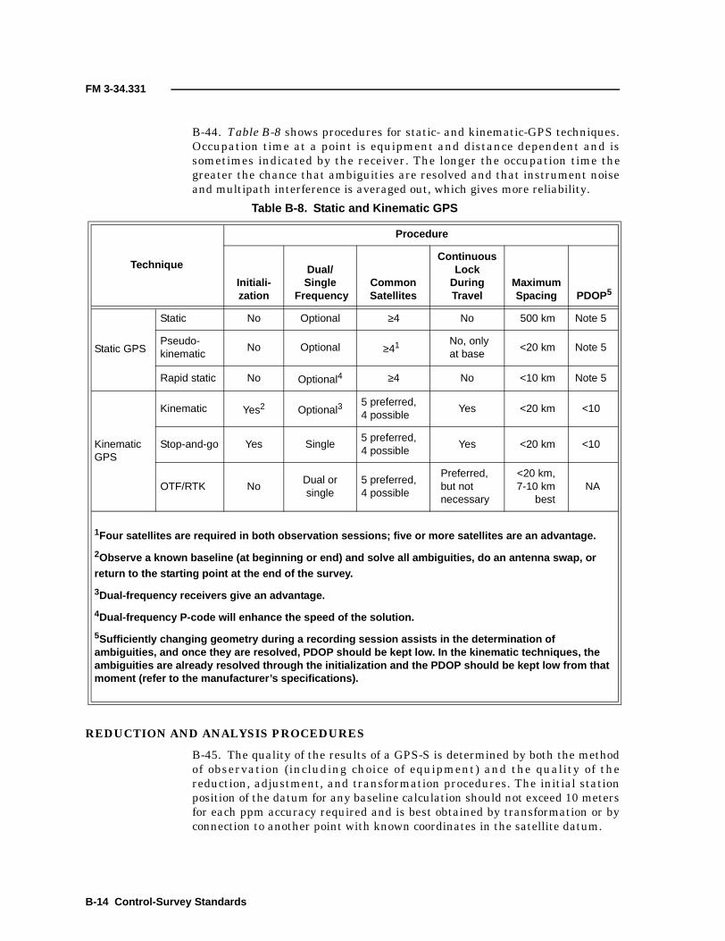
FM 3-34.331
B-44. Table B-8 shows procedures for static- and kinematic-GPS techniques.Occupation time at a point is equipment and distance dependent and issometimes indicated by the receiver. The longer the occupation time thegreater the chance that ambiguities are resolved and that instrument noiseand multipath interference is averaged out, which gives more reliability.
REDUCTION AND ANALYSIS PROCEDURES
B-45. The quality of the results of a GPS-S is determined by both the methodof observation (including choice of equipment) and the quality of thereduction, adjustment, and transformation procedures. The initial stationposition of the datum for any baseline calculation should not exceed 10 metersfor each ppm accuracy required and is best obtained by transformation or byconnection to another point with known coordinates in the satellite datum.
Table B-8. Static and Kinematic GPS
Technique
Procedure
Initiali-zation
Dual/Single
FrequencyCommonSatellites
ContinuousLock
DuringTravel
MaximumSpacing PDOP 5
Static GPS
Static No Optional ≥4 No 500 km Note 5
Pseudo-kinematic
No Optional ≥41 No, onlyat base
<20 km Note 5
Rapid static No Optional4 ≥4 No <10 km Note 5
KinematicGPS
Kinematic Yes2 Optional35 preferred,4 possible
Yes <20 km <10
Stop-and-go Yes Single5 preferred,4 possible
Yes <20 km <10
OTF/RTK NoDual orsingle
5 preferred,4 possible
Preferred,but notnecessary
<20 km,7-10 km
bestNA
1Four satellites are required in both observation sessions; five or more satellites are an advantage.
2Observe a known baseline (at beginning or end) and solve all ambiguities, do an antenna swap, orreturn to the starting point at the end of the survey.
3Dual-frequency receivers give an advantage.
4Dual-frequency P-code will enhance the speed of the solution.
5Sufficiently changing geometry during a recording session assists in the determination ofambiguities, and once they are resolved, PDOP should be kept low. In the kinematic techniques, theambiguities are already resolved through the initialization and the PDOP should be kept low from thatmoment (refer to the manufacturer’s specifications).
B-14 Control-Survey Standards

FM 3-34.331
B-46. The reduction procedures outlined in Table B-9 give a broad overview ofthe essential components to consider when undertaking the reduction of GPSdata. Adhering to the procedures in this table does not remove the necessityfor statistical analysis of the results. The table format gives a clear picture ofthe specific reduction requirements for achieving a given geometric standardof survey. These reduction procedures indicate the minimal requirements.
B-47. Because of the effect of the ionosphere, dual-frequency receivers areused on lines over a certain length. L1-only solutions often show less noise forvector lengths below 10 kilometers. Single-frequency receivers can still satisfyhigh-order survey requirements up to 20 kilometers but need an increasingnumber of hours of observation if a higher order of survey is required or iflonger baselines are observed. Dual-frequency ambiguity-fixed L1/L2solutions in their ion-free linear combination are usually obtained for vectorlengths from 10 to 50 kilometers. An ambiguity-fixed solution is preferred, butas the distance increases, it becomes harder to achieve. Ion-free, ambiguity-float L1/L2 solutions have become more common for vectors of 40 to 90kilometers. For longer baselines, triple-difference solutions can be used if theobservation time is long enough to enable a sufficient change in the satellite
Table B-9. Recommended Processing Requirements
ObservationDistance
Order and Class
1st 2nd, I 2nd, II 3rd, I 3rd, II
<8 km D1, DD, FX D1, DD, FX S, DD, FX S, DD, FX S, DD, FX
8 to 24 km D, DD, FX D, DD, FX D, DD, FX D, DD, FX S, DD, FX
25 to 49 kmD, DD,FX-FT
D, DD,FX-FT
D, DD,FX-FT
D, DD, FX-FT
D, DD, FX-FT
50 to 90 km D, DD,FT DD or T2, D,FT
DD or T2, D,FT
DD or T2, D,FT
DD or T2, D,FT
90> km D, T D, T D, T D, T D, T
1Use L1 solutions from a dual-frequency receiver to enable ambiguity resolutionby widelaning.2Double-difference solutions are preferred. Triple-difference solutions areincreasingly acceptable as the distance increases, and the observation lengthallows sufficient geometry change.
LEGEND:D = dual-frequency receiverDD = double-difference solutionFT = ambiguity-float solution (with repaired cycle slips)FX = ambiguity-fixed solutionS = single-frequency receiverT = triple-difference solution
(with sufficient observation length to allow for a change of geometry)
Control-Survey Standards B-15

FM 3-34.331
geometry during the recording session. As a guide, use 30 minutes as aminimum plus an additional 20 minutes per each 10 kilometers of baselinelength.
PROCESSING AND ANALYSIS OF MINIMALLY CONSTRAINED ADJUSTMENTS
B-48. When processing minimally constrained adjustments, the processingsoftware must be able to produce the variance/covariance statistics of theobserved Cartesian vectors so that the adjustments can be input into a 3Dadjustment program. A least-squares adjustment must be performed whenderiving values for control surveys. The software must be capable ofdetermining transformation parameters between the observed Cartesianvectors and the local geodetic system.
B-49. Error ellipses should be calculated after a minimally constrained least-squares adjustment. These calculations prove the quality of the networkdesign rather than the quality of the observations. The error ellipses shouldbe scaled by the a priori variance of unit weight (generally equal to one),unless the a posteriori estimate of variance does not pass the chi-square test.In the latter case, the observations, the statistical model, or even themathematical model should be examined and the problem remedied and theadjustment rerun. In the case of not being able to remedy the situation, theerror ellipses should be scaled by the a posteriori variance factor.
B-50. To confirm the quality of the observations, the standardized residualsshould be checked for outliers. The checking of the statistics often involvescritical evaluation of the a priori standard deviations of the observations. Ifthe baseline variance/covariance matrix is routinely modified by a multiplier,documentation of a measurement over a test network may be required asconfirmation of the multiplier used.
B-51. To conform to the internal consistency requirements for a particulargeometric accuracy, the error ellipses should confirm the capability of thenetwork design to meet the specifications. The standardized residuals and theestimate of variance should confirm that the observations have actually metthe required standard.
B-52. All points in a survey should conform to the specifications belonging tothe relevant classification. This applies whether the points are connected bybaseline observations or not. This is also valid when relative accuracy valuesare calculated to points with previously established coordinate values. Geoid-separation values are applied to orthometric heights of points that will beconstrained in the transformation and adjustment.
DERIVATION OF GEOID-SEPARATION VALUES
B-53. The following four methods are used for determining geoid heights:
• Geodetic-leveling-geoid method. The use of a geodetic-levelinggeoid.
• Global-geopotential-model method. The use of different types ofglobal-geopotential models derived from gravity and active or passivesatellite information.
B-16 Control-Survey Standards

FM 3-34.331
• Gravimetric method. The use of an intensive grid of local gravity,together with a high-degree global-geopotential model.
• Geometrically modeled geoid method. The use of a geometricallymodeled geoid by contouring geoid-height values derived fromorthometric and ellipsoidal heights.
B-54. The relative accuracy of height values resulting from the global-geopotential-model method are dependent on the grid spacing of thegeopotential model used. The spacing of points with observed local gravity inthe gravimetric method and the spacing of leveled points in the geometricallymodeled geoid method determine the relative accuracy.
B-55. The geodetic-leveling-geoid method is generally not accurate enough toconvert GPS-ellipsoidal heights into orthometric heights but works well withheight differences. The global-geopotential-model method is useful in the caseof long baselines in an area with a smooth geoid and scarce orthometric-heightpoints. The gravimetric method is the most accurate when a sufficient densegrid of gravity information is available. The geometrically modeled geoidmethod is the most accurate when sufficient orthometric information isavailable. When orthometric information is scarce and the geoid is notsmooth, surface fitting and contouring are not recommended for shortdistances (10 kilometers or less).
TRANSFORMATION AND CONSTRAINED ADJUSTMENTS
B-56. The next step is the derivation of transformation parameters betweenthe minimally constrained adjusted vectors and the selected constrainedpoints in the local geodetic system. This is usually carried out together with aconstrained least-squares adjustment. This adjustment is subjected to thesame analysis as the minimally constrained adjustment. Error ellipses arecalculated again and the network is allocated an accuracy order that enablesits orderly integration with the database that contains the existing data set ofestablished coordinates.
NOTE: Refer to EM 1110-1-1003 for a complete sample of anadjustment statistics summary.
Control-Survey Standards B-17

Appendix C
Basic Survey Computations
This appendix contains recommended procedures for performing basicsurvey computations. Until recently, three different forms were used tocompute a two-point intersection. Army units have developed a one-sheetformat (Figure C-1, page C-2) to use when computing a two-pointintersection. This one-sheet format is broken down into three parts andcombines portions of DA Forms 1920, 1938, and 1947. Part I is fromDA Form 1920, Part II is from DA Form 1938, and Part III is fromDA Form 1947.
COMPUTATION OF A TWO-POINT INTERSECTION
C-1. Tabulate data (known and field) for a two-point intersection onDA Form 1962 (Figure C-2, page C-3) or on a blank piece of paper with anidentifying heading. Include the following information:
• A properly oriented sketch of the triangle with the known baselinestations, an unknown station, and any other information that may beneeded to organize computations. Label the unknown point asnumber 1 and the known points (clockwise from the unknown point)as number 2 and number 3.
• The position and elevation of known stations.• The grid azimuth and grid distance of the known baseline.• The observed horizontal angles, ZDs, and HIs.
NOTE: The grid azimuth (denoted by t) and the grid distance may be computed onDA Form 1934 by using UTM coordinates. If needed, conversions can be computed onDA Forms 1932 and 1933.
COMPLETE PART I OF THE ONE-SHEET FORMAT
C-2. Perform the following steps to complete Part I (Figure C-1):
Step 1. Abstract all pertinent information from DA Form 1962 onto Part I.Include the following information:
• Record the—■ Project name.■ Project location.■ Organization performing the survey.■ Date of computation.
• Record the station names (under the station column) oppositetheir respective numbers. Station 1 (unknown station) andStations 2 and 3 (known stations).
Basic Survey Computations C-1

FM 3-34.331
Figure C-1. Sample One-Sheet Format for Basic Survey Computations
Sample
C-2 Basic Survey Computations

FM 3-34.331
Figure C-2. Sample DA Form 1962
Sample
Basic Survey Computations C-3

FM 3-34.331
• Record the observed horizontal angles opposite their respectivenumbers under the observed-angle column.
• Record the distance of the given side (side 2-3) that serves as thebaseline under the distance column.
• Record the station names that correspond to each side under theside column.
Step 2. Complete the following items in Part I:• Compute the unknown angle (number 1) by subtracting the two
observed angles from 180°.• Compute the sine of angle number 1 and record to nine decimal
places with the sign (round the answer).• Compute the side/sine ratio (denoted by D) by dividing the
distance of the given side (side 2-3) by the sine of angle number 1and record to six decimal places (round the answer).
• Compute the sine of angle number 2 and record to nine decimalplaces with the sign (round the answer).
• Compute side 1-3 by multiplying the sine of angle number 2 by Dand record to three decimal places (round the answer).
• Compute the sine of angle number 3 and record to nine decimalplaces with the sign (round the answer).
• Compute side 1-2 by multiplying the sine of angle number 3 by Dand record to three decimal places (round the answer).
COMPLETE PART II OF THE ONE-SHEET FORMAT
C-3. Perform the following steps to complete Part II (Figure C-1, page C-2):
Step 1. Abstract all necessary information from DA Forms 1962 and Part Ionto Part II. Record the–
• Project name.• Project location.• Organization performing the survey.• Ellipsoid name.• Zone number.• Meridian designation.• t (2 to 3).• t (3 to 2).• Angle at Station 2 (∠ 2).• Angle at Station 3 (∠ 3).• Northing and easting of Station 2 (N2 and E2).• Northing and easting of Station 3 (N3 and E3).• Station names opposite their appropriate numbers (for example,
2 ABE, 1 Pole, or 3 CAT).• Grid distance of side 1-2 (from Part I).• Grid distance of side 1-3 (from Part I).
C-4 Basic Survey Computations

FM 3-34.331
Step 2. Complete the following items:• Compute t (2 to 1) by adding ∠ 2 to t (2 to 3). If the sum exceeds
360°, subtract 360°.• Compute the sine of t (2 to 1). Record to nine decimal places with
the sign (round the answer).• Compute the dE by multiplying the sine of t (2 to 1) by the grid
distance of side 2-1. Record to three decimal places with the sign(round the answer).
• Compute E1 by algebraically adding dE and E2. Record to threedecimal places.
• Compute the cosine of t (2 to 1). Record to nine decimal placeswith the sign (round the answer).
• Compute the dN by multiplying the cosine of t (2 to 1) by the griddistance of side 2-1. Record to three decimal places with the sign(round the answer).
• Compute N1 by algebraically adding dN and N2. Record to threedecimal places.
• Compute t (3 to 1) by subtracting the ∠ 3 from t (3 to 2). If ∠ 3 islarger than t (3 to 2), add 360° before subtracting.
• Compute the sine of t (3 to 1). Record to nine decimal places withthe sign (round the answer).
• Compute dE by multiplying the sine of t (3 to 1) by the griddistance of side 3-1. Record to three decimal places with the sign(round the answer).
• Compute E1 by algebraically adding dE and E3. Record to threedecimal places.
• Compute the cosine of t (3 to 1). Record to nine decimal placeswith the sign (round the answer).
• Compute dN by multiplying the cosine of t (3 to 1) by the griddistance of side 3-1. Record to three decimal places with the sign(round the answer).
• Compute N1 by algebraically adding dN and N3. Record to threedecimal places.
NOTE: Compare the two sets of N1 and E1. They must agree to within 0.001. If they donot, then a math or abstraction error was made, and Part II must be recomputed.
COMPLETE PART III OF THE ONE-SHEET FORMAT
C-4. Perform the following steps to complete Part III (Figure C-1, page C-2):
Step 1. Abstract all information from DA Forms 1962 and Part II ontoPart III. Record the–
• Project name.• Project location.• Organization performing the survey.• Date of computation.• Name of the station whose elevation is known (Station 1,
occupied).
Basic Survey Computations C-5

FM 3-34.331
• Name of the station whose elevation is unknown (Station 2,observed).
• Object sighted (for example, target or obstruction light).• Mean observed ZD (denoted by ζ1).• Mean latitude (denoted by φ) and the azimuth of a line (denoted
by α).
NOTE: The azimuth of a line is recorded to the nearest minute and is obtained fromPart II. The mean latitude is obtained by converting the northings and eastingscomputed on Part II to geographic positions and then taking the mean of the latitudes.
• Weighted mean coefficient of refraction (0.5 - m). When this isnot observed, use 0.4290.
• Grid distance (denoted by s) (from Part II).• Elevation of the occupied station (denoted by h1) (from
DA Form 1962).• HI of the station occupied (from DA Form 1962).
Step 2. Compute the elevation by using the following formulas:
• Compute rho (denoted by ρ) sine 1″. Record to three decimalplaces (round the answer). ρ is the mean radius of curvature inthe plane of the distance and will be given (it can be found onDA Form 1962).
where–
R = radius of curvature in the plane of the meridian (obtainedfrom NIMA’s table generating software)
N = radius of curvature in the plane of the prime vertical(obtained from NIMA’s table generating software)
• Compute the correction for the earth’s curvature (denoted by κ)in seconds (denoted by secs). Record to one decimal place (roundthe answer).
κ (in secs)
where—
m = mean coefficient of refraction• Compute (90° - ζ1 + κ). Record to one decimal place (00.1″) with
the sign (κ must be converted to minutes and seconds if it is over60″).
• Compute the tangent of (90° - ζ1 + κ). Record to nine decimalplaces with the sign (round the answer).
• Compute h2 - h1. Record to three decimal places with the sign(round the answer).
h2 - h1 = s • tan(90° - ζ1 + κ)
ρ RN
Rsin2α Ncos
2α+-------------------------------------------=
0.5 m–( )sρ 1″sin
-------------------------=
C-6 Basic Survey Computations

FM 3-34.331
• Compute the corrected elevation by algebraically adding (h2 -h1), h1, and HI.
• Repeat Part III, steps 1 and 2, for observations taken from theother end of the baseline.
• Sign and date the form.
NOTE: Compute the DE between the two computed elevations. Use the followingformula to determine the AE:
Use the shortest of the two distances to the unknown point. If the DE is larger than theAE, check for math and abstraction errors. If none are found, the intersection does notmeet specifications and needs to be reobserved.
COMPUTATION OF A GRID TRAVERSE AND SIDE SHOTS
C-5. DA Form 1940 is used to compute a grid traverse. Tabulate known andfield data for the traverse on a DA Form 1962 (Figure C-3, page C-8) or on ablank piece of notepaper with an identifying heading. Include the following:
• A sketch of the traverse. Include the starting and ending stations, theintermediate stations, and any other information that may be neededto organize the computations.
• The position, the elevation, and the azimuth (if known) for thestarting and ending stations.
• The observed angles and distances.
C-6. Figure C-4, page C-9, shows a completed DA Form 1940. This figure isfurther broken down into separate figures to demonstrate the computationprocess. Refer to Figures C-5 and C-6, page C-10, when working step 1 andFigure C-7, page C-11, when working steps 2 through 7.
Step 1. Transfer the information from DA Form 1962 to DA Form 1940.Record the following information:
• Project name.• Project location.• Organization performing the survey.• From station (starting station).• To station (ending station).• Number of angle stations (number of observed field angles).• Grid zone.• Traverse station names (the first and last columns of
DA Form 1940).• Observed angles (corrected mean station angles).• Corrected field distances.• Starting and ending projected geodetic azimuths (denoted by T).• Mean elevation.• Starting and ending UTM grid coordinates.
AE 0.5 m distance to point in km••••=
Basic Survey Computations C-7

FM 3-34.331
Figure C-3. Observed Angles and Distances on DA Form 1962
Sample
C-8 Basic Survey Computations

FM 3-34.331
Fig
ure
C-4
.S
ampl
eC
ompl
eted
DA
For
m19
40
Sam
ple
Basic Survey Computations C-9

FM 3-34.331
Figure C-5. Example 1 (Portion of DA Form 1940)
Figure C-6. Example 2 (Portion of DA Form 1940)
C-10 Basic Survey Computations

FM 3-34.331
NOTE: The starting and ending T may be obtained from UTM coordinates bycomputing t and (t - T) on DA Form 1934.
Step 2. Compute the summation of angles (∑ ∠s) by adding all of theobserved angles to the starting back azimuth. Leave the sum in decimaldegrees. Record on DA Form 1940 to six decimal places (round the answer).
Step 3. Compute the ending azimuth by subtracting 180º from the ∑ ∠s untilit is as close as possible to the known ending azimuth. Record onDA Form 1940 in degrees, minutes, and seconds. Record seconds to onedecimal place (round the answers).
Step 4. Compute the AEC by subtracting the fixed (known) ending azimuthfrom the computed ending azimuth. Compute to one decimal place with thesign. Record in the “Total Angular Closure” block on DA Form 1940.
Figure C-7. Example 3 (Portion of DA Form 1940)
Basic Survey Computations C-11

FM 3-34.331
NOTE: The AEC is always equal to the computed values minus the fixed values asshown in the following formula:
Computed ending azimuth = 154º31′53.2″Fixed ending azimuth = - 154º32′02.9″AEC = -9.7″
Step 5. Compute the allowable AEC by using the formula from DMS SpecialText (ST) 031. Since this is a third-order, Class I traverse, the formula usedfor computing the AE is ±10″ , where N is the number of segments ordistances. This traverse has four distances; therefore AE = ±10″ = ±20.0″.
NOTE: The AE is always truncated. Do not round up the AE, because rounding willallow more error. Record to one decimal place.
Step 6. Compute the correction per station by dividing the AEC by thenumber of observed angles, then change the sign of the answer. Record to twodecimal places with the sign, and truncate the answer.
= = -(-1.94″) = +1.94″
NOTE: No one angle contains more of the error than another since the angular error isaccidental. The error must be distributed evenly among the station angles.
Step 7. Compute the correction per observed angle and properly assigncorrections to be applied to the observed angles. Record to one decimal placewith the sign. After computing the correction per station, if the division doesnot result evenly to 0.1″, produce a group of corrections that are within 0.1″ ofeach other as in the following example.
C-7. After computing the correction per angle, assign the proper correction toeach angle. For uniformity, apply the larger corrections to the larger angles.Record the correction per station in the “Angular Closure Per Station” blockon DA Form 1940 (for example, 2 @ +2.0″ and 3 @ +1.9″). Sum the corrections.Record in the appropriate block on DA Form 1940.
NOTE: The sum of the corrections must equal the AEC, with the opposite sign. Forexample, if the AEC is negative, the corrections will be positive. If the AEC is positive,the corrections will be negative.
+1.94″ +2.0″
+1.94″ +2.0″ 2 @ +2.0″ = +4.0″
+1.94″ or +1.9″ or
+1.94″ +1.9″
+1.94″ +1.9″ 3 @ +1.9″ = +5.7″
+9.7″ +9.7″ 9.7″ total correction
N
4
Correction per stationAEC–
number of observed angles----------------------------------------------------------------=
09.7″–5
----------------
C-12 Basic Survey Computations

FM 3-34.331
C-8. Refer to Figure C-8 for working steps 1 through 4.
Step 1. Compute the adjusted angles by algebraically adding the correctionper angle to the observed angle. Record to one decimal place.
Step 2. Compute the azimuth of each traverse section by adding the firstadjusted angle to the starting back azimuth. If the azimuth is over 360º,subtract 360º. This is the azimuth to the forward station. The azimuth of alllines must always be stated in the direction that the traverse is beingcomputed.
Step 3. Convert the forward azimuth of the line to a back azimuth by eitheradding or subtracting 180º from the forward azimuth. The forward azimuth tothe next station is then computed by adding the back azimuth from theprevious line to the adjusted angle of the next station. If the new forwardazimuth to the station is greater than 360º, subtract 360º.
Figure C-8. Example 4 (Portion of DA Form 1940)
Starting back azimuth = 63º54′20.3″
Adjusted angle at TILDON = 263º24′15.5″
Forward azimuth: TILDON to AIR FORCE = 327º18′35.8″
Forward azimuth: TILDON to AIR FORCE = 327º18′35.8″- 180º00′00.0″
Back azimuth: TILDON to AIR FORCE = 147º18′35.8″Adjusted angle at AIR FORCE = + 149º47′14.1″Forward azimuth: AIR FORCE to ARMY = 297º05′49.9”
Basic Survey Computations C-13

FM 3-34.331
Step 4. Repeat this procedure until the final station obtains a perfect check.The computed closing azimuth must agree exactly with the known closingazimuth. If not, a math error has been made and must be corrected.
NOTE: It is very important that particular attention be given to the direction of theazimuth. An error of 180º may go undetected, and two errors of 180º will cancel out(providing a final azimuth check). This will result in some sections being reversed indirection. Always refer to the sketch provided with the surveyor’s field notes.
C-9. Refer to Figure C-9 when working steps 1 through 10.
Figure C-9. Example 5 (Portion of DA Form 1940)
C-14 Basic Survey Computations

FM 3-34.331
Step 1. Compute the SLC. Record to six decimal places.
where–h = the mean elevation
R = the mean radius of the earth (If h is in feet, use R = 20,906,000 feet. If his in meters, use R = 6,372,000 meters.)
Step 2. Compute the middle northing (denoted by MID N) and the middleeasting (denoted by MID E). To compute the MID N, add the northing of thebeginning traverse station to the northing of the ending traverse station. Thendivide by two. Record to the nearest 1,000 meters. To compute the MID E, addthe easting of the beginning traverse station to the easting of the endingtraverse station. Then divide by two. Record to the nearest 1,000 meters.
NOTE: A scale factor (denoted by K) is required to convert a measured distance to agrid distance. A mean K may be computed for the entire traverse or for each section inthe traverse. For this example, a single K will be used since the traverse’s total lengthis 8,000 meters or less. Traverses over 8,000 meters require a K to be computed for eachsection. Compute the northing and easting of the midpoint for the desired traverse orsection to the nearest 1,000 meters. Record the formula in the appropriate block onDA Form 1940.
Step 3.Compute K. Record to six decimal places (round the answer).
K = Ko[1 + (XVIII)q2 + 0.00003 q4]
where—Ko = the scale factor at the CM (0.9996)XVIII = the Table 18 valueq = a factor used to convert E′ to millionths
Northing for TILDON = 4,283,839.177 m Easting for TILDON = 314,225.115 m
Northing for ABBOT = + 4,287,595.893 m Easting for ABBOT = + 310,461.502 m
m m
= 4,285,717.535 m = 312,343.3085 m
MID N = 4,286,000 m MID E = 312,000 m
SLC 1hR---– 1
736,372,000------------------------– 0.999989= = =
8,571,435.0702
----------------------------------624,686.617
2------------------------------
Basic Survey Computations C-15

FM 3-34.331
Step 4. Obtain the Table 18 (denoted by XVIII) value. The XVIII value isextracted from the tables in DMS ST 045, using the MID N as the argument.Interpolate to compute the XVIII value to six decimal places (round theanswer). An example follows:
Step 5. Compute E′ by subtracting 500,000 from the MID E. Record to1,000 meters as an absolute value.
E′ = MID E - 500,000 = 312,000 - 500,000 = -188,000 m
where—E′ = absolute value of MID E
MID N XVIII Value
1) 4,200,000 1) 0.012321
2) 4,286,000 2) Unknown
3) 4,300,000 3) 0.012318
≈ 0.012318
MID N (2) MID N (1)–MID N (3) MID N (1)–--------------------------------------------------------
XVIII (2) XVIII (1)–XVIII (3) XVIII (1)–-------------------------------------------------=
4,286,000 4,200,000–4,300,000 4,200,000–------------------------------------------------------
XVIII (2) 0.012321–0.012318 0.012321–---------------------------------------------------=
86,000100,000-------------------
XVIII (2) 0.012321–0.000003–
--------------------------------------------------=
0.86XVIII (2) 0.012321–
0.000003–--------------------------------------------------=
XVIII (2) 0.012321– 0.86 0.000003–( )=
XVIII (2) 0.012321– 0.00000258–=
XVIII (2) 0.012321 0.00000258–=
XVIII (2) 0.01231842=
C-16 Basic Survey Computations

FM 3-34.331
Step 6. Compute q by multiplying E′ by 0.000001. Record to six decimalplaces (round the answer).
q = E′ • 0.000001 = 188,000 • 0.000001 = 0.188000
where—q = a factor used to convert E′ millionths
Step 7. Compute q2 and q4. Record to six decimal places (round the answers).
q2 = 0.1880002 = 0.035344q4 = 0.1880004 = 0.001249
Step 8. Compute K. Record to six decimal places (round the answer).
K = Ko[1 + (XVIII) q2 + 0.00003 q4]= 0.9996[1 + 0.012318 • 0.035344 + 0.00003 • 0.001249]= 1.000035
where—Ko = the scale factor at the CM (0.9996)q = a factor used to convert E′ millionths
Step 9. Compute a scale factor used to reduce the grid distance (denoted byK�) by multiplying K by the SLC. Record to six decimal places (round theanswer).
K� = K • SLC = 1.000035 • 0.999989 = 1.000024
NOTE: After computing K and K�, record the values in the “Scale Factor x SLC” blockson DA Form 1940 beside the appropriate corrected field distance.
Step 10. Compute grid distances as follows.
• Taped distances (corrected horizontal field distances) arereduced to grid distances by multiplying the taped distance byK�.
G = H • K�
where—G = grid distanceH = taped distance
Basic Survey Computations C-17

FM 3-34.331
• EDME distances (reduced geodetic distances) are corrected bymultiplying the geodetic distance by K.
G = S • K
where—G = grid distanceS = geodetic distance
NOTE: Compute the total length of the traverse. Record to three decimal places in the“Length of Traverse” block on DA Form 1940 (Figure C-10).
C-10. Refer to Figure C-11 when working steps 1 through 3:
Step 1. Compute the cosines and sines of the azimuths. Record to sevendecimal places with the sign (round the answer).
Step 2. Compute the dNs and the dEs.
• The dN is computed by multiplying the grid distance by thecosine of the azimuth. Record to three decimal places with thesign (round the answer).
dN = grid distance • cos (t)
• The dE is computed by multiplying the grid distance by the sineof the azimuth. Record to three decimal places with the sign(round the answer).
dE = grid distance • sin (t)
Figure C-10. Example 6 (Portion of DA Form 1940)
C-18 Basic Survey Computations

FM 3-34.331
Step 3. Compute errors in the dN and the dE (denoted by En and Ee).
• Compute the En by using the following formula. Record to threedecimal places with the sign.
En = computed dN - fixed dN
Algebraically add the column of dNs to get the computed dN.Record to three decimal places with the sign.
+1,357.957+1,720.902
+567.159__+110.373
Computed dN = +3,756.391
Subtract the fixed starting northing from the fixed endingnorthing to get the fixed dN. Record to three decimal places withthe sign.
Fixed ending northing = +4,287,595.893Fixed starting northing = +4,283,839.177Fixed dN = +3,756.716
En = computed dN - fixed dN = +3,756.391 - (+3,756.716) = -0.325
Figure C-11. Example 7 (Portion of DA Form 1940)
Basic Survey Computations C-19

FM 3-34.331
• Compute the Ee by using the following formula. Record to threedecimal places with the sign.
Ee = computed dE - fixed dE
Algebraically add the column of dEs to get the computed dE.Record to three decimal places with the sign.
-871.461-3,363.344
+450.363+21.115
Computed dE = -3763.327
Subtract the fixed starting easting from the fixed ending eastingto get the fixed dE. Record to three decimal places with the sign.
Fixed ending easting = +310,461.502Fixed starting easting = +314,225.115Fixed dE = -3,763.613
Ee = computed dE - fixed dE = -3,763.327 - (-3,763.613) = +0.286
C-11. Refer to Figure C-12 when working steps 1 through 5.
Step 1. Compute the LEC. Record to four decimal places in the “LinearClosure Ratio” block on DA Form 1940. Compute the LEC by using thefollowing formula:
Step 2. Compute the RC. Round down to the nearest 100. Record in the“Linear Closure Ratio” block on DA Form 1940. Compute the RC by dividingthe length of traverse (in meters) by the LEC. Use the following formula:
Step 3. Compute the AE for position closure. Since this is a third-order,Class I traverse, the AE for position closure is equal to 0.4 times the squareroot of the distance of the traverse in kilometers. Compute the AE for positionclosure by using the following formula (found in DMS ST 031) (truncate andrecord the answer to four decimal places):
where—k = the distance of the traverse in kilometers
LEC En2
Ee2
+ 0.325–( )20.286
2+= =
0.105625 0.081796+= 0.4329=
RC 1:length of traverse (m)
LEC---------------------------------------------------- 1:
6 228.170,0.4329( )
------------------------- 1:14,387.087 1:14,300= = = =
AE 0.4( ) k = (0.4) 6.22817 0.9982= =
C-20 Basic Survey Computations

FM 3-34.331
NOTE: The LEC must be compared to the AE. If the LEC is equal to or less than the AE,the traverse has met specifications. If the LEC is greater than the AE, no furthercomputations are necessary.
Step 4. Compute the correction factors (correction to northing [denoted byKN] and correction to easting [denoted by KE]) to be used in adjusting thetraverse.
• KN is computed by dividing the En by the length of traverse inmeters then changing the sign of the answer. Record to sevendecimal places with the sign (round the answer).
• KE is computed by dividing the Ee by the length of traverse inmeters then changing the sign of the answer. Record to sevendecimal places with the sign (round the answer).
Figure C-12. Example 8 (Portion of DA Form 1940)
KNEn
length of traverse------------------------------------------
–-0.325
6,228.170------------------------
+0.0000522=–= =
KEEe
length of traverse------------------------------------------
–+0.286
6,228.170------------------------
– 0.0000459–= = =
Basic Survey Computations C-21

FM 3-34.331
NOTE: A correction factor will always have the opposite sign of the En and the Ee.
Step 5. Compute corrections to dNs and dEs.
• Corrections to dNs are computed by multiplying KN by the griddistance. This is done for each section of the traverse. Record tothree decimal places with the sign (round the answer).
Correction to dN = KN • grid distance= +0.0000522 • 1,613.534 (first distance)= +0.084
• Corrections to dEs are computed by multiplying KE by the griddistance. This is done for each section of the traverse. Record tothree decimal places with the sign (round the answer).
Correction to dE = KE • grid distance= -0.0000459 • 1,613.534 (first distance)= -0.074
• After all the corrections are recorded, sum the columns. The sumof the corrections must equal the errors of dN and dE with theopposite sign. If, because of rounding errors, the sum does notexactly equal the error of dN or dE, this difference must bedistributed. For uniformity, the largest corrections are changedby one unit (third decimal place) until the correct sum isobtained.
• The sum of the dN corrections is exactly equal to the error(-0.325) with the opposite sign.
• The sum of the dE corrections is different by 0.001 from the error(+0.286). Therefore, an additional 0.001 is applied to the largestcorrection (0.173).
dN dECorrection
to dE New dE
+0.084 -0.074 -0.074
+0.197 -0.173 -0.001 -0.174
+0.038 -0.033 -0.033
+0.006 -0.005 -0.005
+0.325 -0.285 -0.286
C-22 Basic Survey Computations

FM 3-34.331
C-12. Refer to Figure C-13 when working steps 1 and 2.
Step 1. Compute the adjusted grid coordinates (northings and eastings).
• To compute the adjusted northing, algebraically add the dN andthe correction of dN to the northing of the preceding station.Record to three decimal places.
• To compute the adjusted easting, algebraically add the dE andthe correction of dE to the easting of the preceding station.Record to three decimal places.
NOTE: Continue in a like manner for each station. As a math check, apply the last dNand the last correction of dN to the northing of the preceding station. The answer mustequal the fixed northing of the closing station. The same is true for the easting.
Step 2. Sign and date the form.
Figure C-13. Example 9 (Portion of DA Form 1940)
dN = +1,357.957
Correction to dN = +0.084
Northing for TILDON = +4,283,839.177
Northing for AIR FORCE = +4,285,197.218
dE = -871.461
Correction to dE = -0.074
Easting for TILDON = +314,225.115
Easting for AIR FORCE = +313,353.580
Basic Survey Computations C-23

FM 3-34.331
COMPUTATION OF A C-FACTOR
C-13. Compute the C-factor. Record on DMS Form 5820-R. Refer toFigure C-14 and Figure C-15, page C-26, when working steps 1 through 15.The step numbers correspond to the numbered blocks on Figure C-14.Figure C-15 shows a completed DMS Form 5820-R.
Step 1. Complete the heading information (1).
Step 2. Record the stadia constant for the instrument (2).
Step 3. Record the backsight-rod (near-rod) readings (in millimeters) (3a).
• Compute and record stadia intervals (in millimeters) (3b). If thedifference is greater than 3, reobserve.
• Compute and record the sum of the intervals (3c).• Compute and record the mean middle-wire reading (in
millimeters) to one decimal place (3d).• Compute and record the sum of the three-wire readings (in
millimeters) (3e).Step 4. Record the foresight-rod (far-rod) readings (in millimeters) (4a).
• Compute and record the stadia intervals (in millimeters) (4b). Ifthe difference is greater than 3, reobserve.
• Compute and record the sum of the intervals (4c).• Compute and record the mean middle-wire reading (in
millimeters) to one decimal place (4d).• Compute and record the sum of the three-wire readings (in
millimeters) (4e).Step 5. Record the backsight-rod (near-rod) readings (in millimeters) (5a).
• Compute and record the stadia intervals (in millimeters) (5b). Ifthe difference is greater than 3, reobserve.
• Compute and record the sum of the intervals (5c).• Compute and record the mean middle-wire reading (in
millimeters) to one decimal place (5d).Step 6. Record the foresight-rod (far-rod) readings (in millimeters) (6a).
• Compute and record the stadia intervals (in millimeters) (6b). Ifthe difference is greater than 3, reobserve.
• Compute and record the sum of the intervals (6c).• Compute and record the mean middle-wire reading (in
millimeters) to one decimal place (6d).Step 7. Compute and record the cumulative totals as follows:
3e + the sum of the second set of near-rod readings from 5a (7a)3d + 5d (7b) (perform a page check 7a ÷ 3)3c + 5c (7c)4e + the sum of the second set of near-rod readings from 6a (7d)4d + 6d (7e) (perform a page check 7d ÷ 3)4c + 6c (7f)7f - 7c (7g)
C-24 Basic Survey Computations

FM 3-34.331
Fig
ure
C-1
4.D
MS
For
m58
20-R
Sam
ple
Basic Survey Computations C-25

FM 3-34.331
Fig
ure
C-1
5.S
ampl
eC
ompl
eted
DM
SF
orm
5820
-R
Sam
ple
C-26 Basic Survey Computations

FM 3-34.331
Step 8. Apply the correction for C&R. Due to the short distance from theinstrument to the near rod, no corrections are required to the near-rodreadings.
• Use the far-rod distance (4c ÷ 10) as an argument to determinethe second correction. Table C-1 shows correction factors forC&R according to the observed distance. Record the correctionfrom Table C-1 in the C&R number 1 block (8b).
• Use the far-rod distance (6c ÷ 10) as an argument to determinethe correction. Record the correction from Table C-1 in the C&Rnumber 2 block (8c).
• Correct the sum of the far-rod mean middle-wire readings forC&R. Algebraically add the sum of 8b and 8c to 7e. Since thecorrection is always negative, just subtract 8b and 8c from 7e(8d).
• Algebraically add 8d and 7b. Record the sum with the sign (8e).8d is always negative.
Step 9. Compute the C-value by dividing 8e by 7g. Truncate and record tofour decimal places with the sign (9).
NOTE: If the sum of the far-rod mean middle-wire readings (8d) is larger than the sumof the near-rod mean middle-wire readings (7b), the C-value is negative.
Step 10. Compare the C-value with that allowed for the instrument. Theallowable C-value in most instruments is +0.004. If the C-value is withinspecifications, no further computations are required.
Step 11. Correct the C-value if it is not within the specifications.
• The correction to the middle wire (in millimeters) is computed bymultiplying the sum of the rod intervals of the last foresight(shown in 6c) by the C-value (shown in 9). Compute to onedecimal place (round the answer) (11a).
Table C-1. Correction Factors for C&R
Distance (m) Correction to Rod (m)
0 to 27.0 - 0.0
27.1 to 46.8 - 0.1
46.9 to 60.4 - 0.2
60.5 to 71.4 - 0.3
71.5 to 81.0 - 0.4
81.1 to 89.5 - 0.5
89.6 to 97.3 - 0.6
97.4 to 104.5 - 0.7
Basic Survey Computations C-27

FM 3-34.331
• The correction to the middle wire (11a) is added algebraically tothe last foresight middle-wire rod reading (shown in 6a) to obtainthe corrected rod reading. Compute to three decimal places(divide the correction by 1,000 to convert to meters beforeapplying) (round the answer) (11b).
Step 12. Initial the form (12).
Step 13. Perform field adjustments.
Step 14. Repeat steps 1 through 13 until the C-value is within specifications.
Step 15. Give the recording form to the instrument operator once it has beendetermined that the instrument is within specifications. The instrumentoperator will check the form for completeness and the computations forcorrectness and initial the form (15).
COMPUTATION OF A LEVEL LINE
C-14. Compute a level line on DA Form 1942. Refer to Figure C-16, page C-30,when working steps 1 through 20 (the step numbers correspond to thenumbered blocks). Figure C-17, page C-31, shows a completed DA Form 1942.Data will be required from the field notes (DA Form 5820) shown inFigures C-18 through C-21, pages C-32 through C-35.
Step 1. Complete the headings (1).
Step 2. Record the name of the–
• Beginning BM (2a).• BM whose elevation is being computed (2b).• Ending BM (2c).
Step 3. Record the name of the–
• Beginning BM for each section (3a).• Ending BM for each section (3b).
Step 4. Record the name of the beginning BM (4).
Step 5. Record the direction of the run (forward [F] or backward [B]) (5).
Step 6. Abstract the length of the forward and backward runs per sectionfrom the level field notes. Record to the nearest 0.001 kilometer, in theirrespective directions (6).
Step 7. Compute the length of the line by adding the shortest distance ofeach section of the level line (7a). Record the total length of the line (7b).
Step 8. Compute the observed DE of the forward and backward runs persection from the level field notes. Record to four decimal places with the sign(in their respective running directions) (8).
Step 9. Compute the DE between the forward and the backward runs persection. Record to four decimal places as an absolute value (no algebraic signs) (9).
C-28 Basic Survey Computations

FM 3-34.331
Step 10. Determine the mean DE by computing the absolute mean of theforward and the backward DE. Give the mean DE the algebraic sign of theforward run. Record to four decimal places (round the answer) (10).
Step 11. Record the known elevation of the beginning BM (11).
Step 12. Record the known elevation of the ending BM (12).
Step 13. Compute the observed elevation by algebraically adding the meandifference (shown in 10) and the elevation of the beginning BM (shown in 11).Record to four decimal places (13a). Compute each successive observedelevation by algebraically adding it to the preceding elevation and therespective section’s mean DE. Record to four decimal places (13b).
NOTE: The last entry will be the observed elevation of the ending BM. This entry mustbe compared to the fixed ending elevation.
Step 14. Record the known elevation of the ending BM (from step 12) (14).
Step 15. Compute the closure by subtracting the known elevation of theending BM (shown in 14) from the computed observed elevation of the endingBM (shown in 13b). Record to four decimal places with the sign (15).
Step 16. Compute the AE. Truncate and record to four decimal places (16).For third-order specifications, use the following formula:
where—
Km = length of line in kilometers (from 7b)
Compare the AE (16) to the closure (shown in 15). If the numerical value ofthe closure is equal to or smaller than the AE, the level line meets third-orderspecifications. If it does not, there is no need to continue with thecomputations on DA Form 1942.Step 17. Compute the correction per kilometer. Divide the closure (shown in15) by the total length of the line (shown in 7b) and change the sign. Record tosix decimal places with the sign (round the answer) (17).
Step 18. Compute the correction for each section. Multiply the length of theline (shown in 7a) of each section by the correction per kilometer (shown in17). Record to four decimal places with the sign (round the answer) (18).
NOTE: The correction to the final section must be equal to the closure (15), with theopposite sign.
Step 19. Compute the adjusted elevation. Algebraically add the correction(shown in 18) to the observed elevation (shown in 13a) of each station. Recordto four decimal places (round the answer) (19).
Step 20. Sign and date the form (20).
AE 0.012± Km•=
Basic Survey Computations C-29

FM 3-34.331
C
Fig
ure
C-1
6.D
AF
orm
1942
Sam
ple
-30 Basic Survey Computations
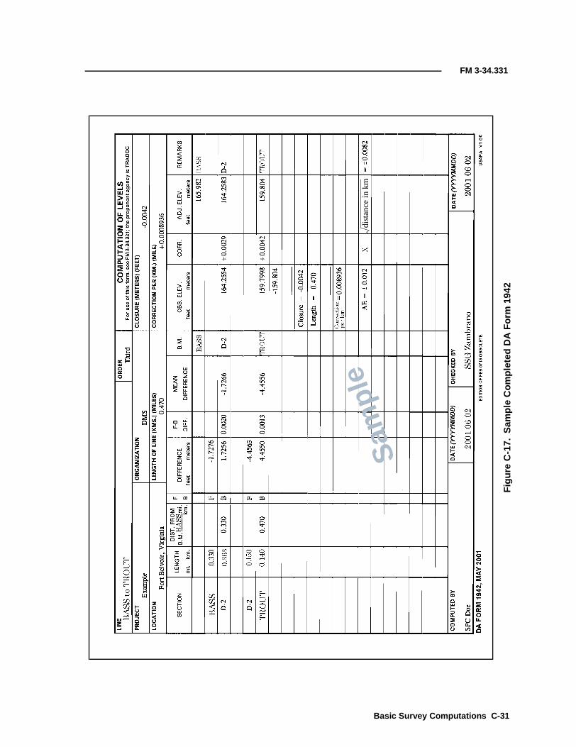
FM 3-34.331
Fig
ure
C-1
7.S
ampl
eC
ompl
eted
DA
For
m19
42
Sam
ple
dist
ance
inkm
Basic Survey Computations C-31

FM 3-34.331
C-32 B
Fig
ure
C-1
8.D
AF
orm
5820
(BA
SS
toD
2)
Sam
ple
asic Survey Computations

FM 3-34.331
Fig
ure
C-1
9.D
AF
orm
5820
(D2
toB
AS
S)
Sam
ple
Basic Survey Computations C-33

FM 3-34.331
Fig
ure
C-2
0.D
AF
orm
5820
(D2
toT
RO
UT
)
Sam
ple
C-34 Basic Survey Computations

FM 3-34.331
Fig
ure
C-2
1.D
AF
orm
5820
(TR
OU
Tto
D2)
Sam
ple
Basic Survey Computations C-35

Appendix D
Survey Forms
Surveyors use a variety of forms in the accomplishment of their duties.Table D-1 includes a list of forms (not addressed in this manual) used bysurveyors.
Table D-1. Survey Forms
Number Title Date
DA Form 1900 Conversion of Mean Time to Sidereal Time 1 February 1957
DA Form 1901 Conversion of Sidereal Time to Mean Time 1 February 1957
DA Form 1902 Conversion of Mean Time to Apparent Time 1 February 1957
DA Form 1903 Azimuth by Direction Method 1 February 1957
DA Form 1905 Azimuth by Hour Angle Method February 1957
DA Form 1907 Azimuth by Altitude Method July 2001
DA Form 1909Longitude by the Altitude of Stars Near the PrimeVertical
February 1957
DA Form 1911 Altitude and Azimuth (Sin-Cos) 1 February 1957
DA Form 1915Abstract of Levels and Computation of InclinationCorrections
1 February 1957
DA Form 1917 List of Directions 1 February 1957
DA Form 1918 Computation of Triangles 1 February 1957
DA Form 1930 Special Angle Computation 1 February 1957
DA Form 1931 Traverse Computation (Geographic) 1 February 1957
DA Form 1935 Grid Azimuth (t) and Grid Length 1 February 1957
DA Form 1936 List of Directions, UTM Grid 1 February 1957
DA Form 1937 Computation of Triangles (UTM Grid) 1 February 1957
DA Form 1939 Reduction of Taped Distances February 1957
DA Form 1941 Grid and Declination Computations February 1957
DA Form 1944Computation of Elevations and Refractions FromReciprocal Observations (Logarithmic)
February 1957
DA Form 1953 Universal Polar Stereographic Transformations February 1957
DA Form 1954Plane Coordinates From Geographic Coordinates onthe Transverse Mercator Projection (CalculatingMachine Computation)
1 February 1957
DA Form 1955Geographic Coordinates From Transverse MercatorGrid Coordinates (Calculating Machine Method)
February 1957
DA Form 1957Geographic Coordinates From Lambert GridCoordinates (Calculating Machine Computation)
February 1957
Survey Forms D-1

FM 3-34.331
DA Form 2839 Latitude From Zenith Distance of Polaris October 1964
DA Form 2847 Comparison of Chronometer and Radio Signals 1 October 1964
DA Form 2856 Field Sheet, Tellurometer Data Entries (MRA3 MK11) October 1964
DA Form 2857 Field Sheet, Micro-Chain Data Entries 1 October 1964
DA Form 4446 Level, Transit, and General Survey Record November 1975
DA Form 4648 Station Description Book September 1977
DA Form 5818 General Survey Notes (LRA) August 1989
Table D-1. Survey Forms (continued)
Number Title Date
D-2 Survey Forms

Glossary
perspective to∠∠∠∠ angle(s)°°°° degree(s)a azimuth of lineαααα angleκκκκ correction for the earth’s curvature���� sum′′′′ minute(s)″″″″ second(s)∆∆∆∆ delta
∆∆∆∆E delta easting∆∆∆∆N delta northing
φφφφ latitudeΦΦΦΦ phi
h1 elevation of the occupied station
λλλλ longitudeθθθθ Thetaρρρρ symbol for rho - radius of curvatures grid distanceσσσσ sigmaττττ tauζζζζ mean observed zenith distance
1D one dimensional1DRMS 1-deviation root-mean-square
1LT first lieutenant1SG first sergeant
2D two dimensional2DRMS 2-deviation root-mean-square
3D three dimensional3DRMS 3-deviation root-mean-square
A/M angle measureAAF Army airfieldAAL additional authorizations list
AC alternating current
Glossary-1

FM 3-34.331
accuracy the degree of conformity with a standard or the degree ofperfection attained in a measurement; accuracy relates to thequality of a result and is distinguished from precision, whichrelates to the quality of the operation used to obtain the result
actual error the difference between the accepted value and the measured valueof a physical quantity
ADA air-defense artilleryadj adjusted
adjust adjustmentadjusted position an adjusted value for the horizontal or vertical position of a survey
station, in which discrepancies due to errors in the observed dataare removed, that forms a coordinated and correlated system ofstations
AE allowable errorAEC angular error of closure
aeronautical beacon a visual NAVAID displaying flashes of white and/or colored lightto indicate the location of an airport, a heliport, a landmark, acertain point of a federal airway in mountainous terrain, or anobstruction
AG Adjutant GeneralAH ampere-hour
air-navigation facility any facility used in, available for use in, or designed for use in theaid of air navigation (this includes landing areas; lights; anyapparatus or equipment used for disseminating weatherinformation, signaling, radio-directional finding, or radio or otherelectrical communication; and any other structure or mechanismhaving a similar purpose of guiding or controlling the flight, thelanding, or the takeoff of aircraft)
airport elevation the highest point of an airport’s usable runways measured in feetfrom the MSL
airport lighting various lighting aids installed on airports. These aids can include1) airport rotating beacons—a visual NAVAID that is operated atmany airports. At civil airports, alternate white and green flashesindicate the location of the airport. At military airfields, thebeacon is differentiated by dual peak (two quick) white flashesbetween the green flashes;2) approach-light systems (ALSs)—an airport lighting facilitywhich provides visual guidance to landing aircraft by radiatinglight beams in a directional pattern by which the pilot aligns theaircraft with the extended runway centerline on his final approachfor landing. A number of ALS configurations exist, both with andw i th o u t s e q u e n c e d f l as h in g l i g h ts . O n e s y s t e m , t h eomnidirectional ALS (ODALS), consists of seven omnidirectionalflashing lights located in the approach area of a nonprecisionapproach. Five of the lights are located on the extended runwaycenterline and the other two lights are located one on each side ofthe runway threshold;
2-Glossary

FM 3-34.331
3) REILs—two synchronized flashing lights, one on each side ofthe runway threshold, provide rapid and positive identification ofthe approach end of a runway;4) visual-approach slope indicators (VASI)—an airport lightingfacility providing vertical visual-approach slope guidance toaircraft during the approach for landing by radiating a directionalpattern of high-intensity, red and white, focused light beams,which indicate to the pilot if he is above, below, or on the glidepath. The term VASI also has a generic connotation for a tricolor-approach slope indicator consisting of a single light unit projectinga three-color, visual-approach path into the final approach area ofthe runway served by the system;5) pulse-light approach-slope indicators (PLASI)—a VASI,normally consisting of a single light unit projecting a pulsatingtwo-color, visual-approach path into the final approach area of therunway served by the system; and6) precision approach-path indicators (PAPI)—a VASI, consistingof a single row of two or four light units, usually installed on theleft side of the runway served by the system
airport reference point the position of the approximate center of mass of all usablerunways. This point is not strictly the center of mass of runways,since the runway width, thickness, or material is not considered inthe computation. An ARP is not monumented; therefore, it is notrecoverable on the ground
airport surveillanceradar
approach control radar that is used to detect and display anaircraft’s position in the terminal area. The ASR provides rangeand azimuth information but does not provide elevation data(coverage of the ASR can extend up to 60 nautical miles)
air-route surveillanceradar
air-route traffic control center (ARTCC) radar used primarily todetect and display an aircraft’s position while en route betweenterminal areas (coverage of the ARSR can extend up to 200nautical miles)
AISI automated integrated survey instrumentALP airport location pointALS approach-light system
altimeter an aneroid barometer that is used for the measurement ofapproximate elevations or approximate differences of elevation
altitude the vertical angle that is measured between the plane of theobserver’s true horizon and a line to the object
ambiguity resolution with carrier-phase observations, the number of carrier-phasecycles between the receiver and the satellite is generally unknownand is referred to as the ambiguity and is an integer number.Single and double differences are also affected by ambiguities,which are formed by a linear combination of carrier-phase integerambiguities (for example, a single or double differencedambiguity). Where the integer ambiguities are unknown, theymay be estimated by processing software. In some cases, thesereal-valued estimates may be used to determine the correctinteger values, which are then held fixed. A float solution is derivedwhen the real-valued estimates are used, rather than the integers
Glossary-3

FM 3-34.331
ang angleant antennaAO area of operation
AOC airport obstruction chartAP airport plan
APFT Army physical fitness testapprox approximate
Apr Aprilapron a defined area on an airport or heliport intended to accommodate
aircraft for purposes of loading and unloading passengers or cargo,refueling, parking, or maintenance (seaplanes use a ramp foraccess from the water to the apron)
AR Army regulationARP airport reference point
ARSR air-route surveillance radarARTCC air-route traffic control centerARTEP Army Training and Evaluation Program
AS antispoofingASCII American Standard Code for Information Interchange
ASPRS American Society of Photogrammetry and Remote SensingASR airport surveillance radar
astronomical latitude the angle between the plumb line and the plane of the celestialequator; also defined as the angle between the plane of the horizonand the axis of rotation of the earth. Astronomical latitude appliesonly to positions on the earth and is reckoned from the astronomicequator (0°), north and south through 90°. Astronomical latituderesults directly from observations of celestial bodies, which areuncorrected for deflection of the vertical
astronomical longitude the angle between the plane of the celestial meridian and theplane of an initial meridian that is arbitrari ly chosen.Astronomical longitude results directly from observations oncelestial bodies, uncorrected for deflection of the vertical
ATC air traffic controlAug August
az azimuthazimuth the direction of one object from another, usually expressed as an
angle in degrees relative to true north (azimuths are usuallymeasured in the clockwise direction, thus an azimuth of 90°indicates that the second object is due east of the first)
azimuth mark the azimuth to a marked point or adjacent station that is visiblefrom an occupied station, which is determined for use independent surveys
4-Glossary

FM 3-34.331
b backwardbacksight in traversing, a backsight is a sight on a previously established
traverse or triangulation station, which is not the closing sight onthe traverse; in leveling, a backsight is a reading on a rod that isheld on a point whose elevation has been previously determinedand is not the closing sight of a level line
BAQ basic allowance for quartersbase network a small network of geometric figures that is used to expand from a
baseline to a line of the main scheme of a triangulation networkbaseline a surveyed line that is established with more than usual care, to
which surveys are referred for coordination and correlation; inGPS baseline reduction, geodetic parameters are estimated at onestation relative to another, with the receivers at both sitesobserving common satellites simultaneously
basic control horizontal and vertical control of third- or higher-order accuracy( d e t e r m in e d in t h e f ie l d a n d pe r m a n e n t l y m a r k e d o rmonumented) that is required to control further surveys
BC basic controlBCM basic-control marker
bearing the direction of one object from another, usually expressed as anangle in degrees relative to a specific primary direction (bearingsdiffer from azimuths in that bearing values do not exceed 90°)
benchmark a relatively permanent object, natural or artificial, bearing amarked point whose elevation above or below an adopted datum isknown; usually designated as a BM, such a mark is sometimesfurther qualified as a PBM or as a temporary BM (TBM)
BEQ bachelor enlisted quartersbde brigade
BDE backward difference in elevationBII basic issue items
blast pad a specially prepared surface that is placed adjacent to the ends ofrunways to eliminate the erosive effect of the high wind forcesproduced by airplanes at the beginning of their takeoff rolls
BM benchmarkbn battalion
broadcast ephemeris the predicted satellite position in its orbit as a function of timecomputed from the ephemeris parameters contained in thenavigation message broadcast on both the L1 and L2 carrierwaves
bs backsightbtry battery
C2 command and control
C CelsiusC/A-code coarse-acquisition code
Glossary-5

FM 3-34.331
CAD computer-aided designcadastral survey a survey relating to land boundaries and subdivisions, which is
made to create units suitable for the transfer of or to define thelimitations of a title; surveys of the public lands of the US,including retracement surveys for the identification of andresurveys for the restoration of property lines; and forcorresponding surveys outside the public lands, although suchsurveys are usually termed land surveys
CADD computer-aided design and draftingcarrier phase the phase (as measured at the antenna phase center of a GPS
receiver) of two sinusoidal radio signals (the two carriers) that arecontinuously emitted by each GPS satellite
C-check collimation test for levelingCDC consecutive Doppler counts
celestial equator a great circle on the celestial sphere on which any point isequidistant from the celestial poles (the plane of the earth’sequator, if extended, would coincide with that of the celestialequator)
celestial meridian a vertical circle (the plane of which is perpendicular to thecelestial equator) passing through both celestial poles
celestial pole a reference point located at the point of intersection of anindefinite extension of the earth’s axis of rotation and theapparent celestial sphere
celestial sphere an imaginary sphere of infinite radius, with the earth as thecenter, that rotates from east to west on a prolongation of theearth’s axis
central meridian the longitude of the horizontal center of a coordinate system (thislongitude value is often the longitude origin of the coordinatesystem); in the case of the transverse Mercator projection, the CMis the great circle/geodesic at which the projection surface (thecylinder) touches or is tangent to the earth
CEOI communications-electronics operation instructionsCEP circular error probable
CESI communications-electronics standing instructionC-factor collimation error; error of the sighting of the level
chron chronometerchronometer a portable timekeeper with compensated balance, which is capable
of showing time with extreme precision and accuracyCID continuously integrated Doppler
circle position a prescribed setting (reading) of the horizontal circle of a directiontheodolite, which is used for observing the initial station of aseries of stations
circuit closure in leveling, it is the amount by which the algebraic sum of themeasured differences of elevation around a circuit fails to equalzero
6-Glossary

FM 3-34.331
circumpolar star a star in any given latitude that never goes below the horizon;hence, its polar distance must be less than the given latitude; inastronomy, only those stars with a polar distance of less than 10°are considered in practical problems
cl closureC/L centerline
clearway an area beyond the takeoff runway that is under the control ofairport authorities where terrain or fixed obstacles may notextend above specified limits (these areas may be required forturbine-powered operations and the size and upward slope of theclearway will differ depending on when the aircraft was certified)
cm centimeter(s)CM central meridian
COEI components of end itemcollimation the line of sight or aiming line of an instrument when coincident
with the physical alignment of the instrument; thus, a collimationerror is the angle between the line of collimation (line of sight) of atelescope and the collimation axis of the instrument
comm communicationcomp computer
compass locator a low-power, low- or medium-frequency (L/MF) NDB that isinstalled at the site of the outer or middle marker (MM) of an ILS(it can be used for navigation at distances of about 15 miles or asauthorized in the approach procedure)
control the coordinated and correlated dimensional data, which are usedin geodesy and cartography to determine the positions andelevations of points on the earth’s surface or on a cartographicrepresentation of that surface; a collective term for a system ofmarks or objects on the earth or on a map or a photograph whosepositions or elevations, or both, have been or will be determined
control survey a survey that provides positions (horizontal or vertical) of points towhich supplementary surveys are adjusted
CONUS continental United Statescoordinate system an exact definition of a system of mathematics and geodetic
constants that defines how a specific geographic location isconverted to a set of two or three numbers (for example, an X- andY-value [and possibly a Z-value]); in the cartographic context,most coordinate systems are Cartesian (the axes are orthogonal[perpendicular to each other]) and the units are the same on allaxes; the principle exception to this is the spherical coordinatesystem of latitudes and longitudes
coordinates linear and/or angular quantities, which designate the position of apoint in relation to a given reference frame; there are two generaldivisions of coordinates used in surveying—polar and rectangular;these may be further subdivided into three classes—planecoordinates, spherical coordinates, and space coordinates
coords coordinates
Glossary-7

FM 3-34.331
Corps Conversion a software program that converts horizontal coordinates to andfrom geographic, state-plane, and UTM systems on the NAD 27and the NAD 83 and converts vertical coordinates on theNGVD 29 and the NAVD 88
Corpscon Corps Conversioncorr correction
CORS continuously operating reference stationcos cosine
CPT captainC&R curvature and refractionCTT common training task
cycle slips cycle slips occur when there are breaks in the continuity of signalin a satellite-receiver pair. Data sampling requires the choosing ofthe sampling rate and the starting and finishing epochs for theobservations. Data editing is required for cycle slips and for datasampling
D ratio of side/sineDA Department of the Army
datum the combination of an ellipsoid, that specifies the size and shape ofthe earth, and a base point from which the latitude and longitudeof all other points are referenced. Before satellites, lasers, andcomputers, establishing precise values for these points wasimpossible. More recently, many datums have been establishedand substantial amounts of data collected based on each. Databased on one datum will not necessarily overlay data based onanother datum. A geodetic datum is a reference surface consistingof five quantities: the latitude and longitude of an initial point, theazimuth and distance of a line from this point, and the parametersof the reference ellipsoid. It forms the basis for the computation ofhorizontal-control surveys in which the curvature of the earth isconsidered. A leveling datum is a level surface to which elevationsare referred (usually, but not always, the MSL)
DD Department of DefensedE difference in eastingDE difference in elevation
declination in a system of polar or spherical coordinates, the angle at theorigin between a line to a point and the equatorial plane,measured in a plane perpendicular to the equatorial plane; the arcbetween the equator and the point measured on a great circle,which is perpendicular to the equator; as it relates to astronomy,the angular distance to a body on the celestial sphere that ismeasured north or south through 90° from the celestial equatoralong the hour circle of the body. Comparable to latitude on theterrestrial sphere and often used as a shortened term for magneticdeclination
8-Glossary
FM 3-34.331
deflection of thevertical
the angular difference, at any place, between the upward directionof a plumb line (the vertical) and the perpendicular (the normal) tothe reference spheroid. This difference seldom exceeds 30 secondsand is often expressed in two components—meridian and primevertical
deg degree(s)det detachmentdev deviation
DGPS differential global-positioning systemdH difference in the horizontal aim
diff differencedifferencing nondifferencing (one-way phase) is the measured carrier phase
between one satellite and one receiver. Single differencing (firstdifference) is the difference between one-way measurementsre corded at tw o re ceiv ers ( fo r ex ample , t wo rece ive rssimultaneously observing a common satellite and differencing therecorded measurements). Double differencing (second difference)is the difference between two single differences (for example, twostations observing two satellites, forming differences between thesite pair and the satellite pair). Triple differencing (doubledifference rate/epoch differences) is the differencing of doubledifferences between consecutive epochs
dir directiondirect leveling the determination of DEs by the means of a continuous series of
short horizontal lines. Vertical distances from these lines toadjacent ground marks are determined by direct observations ongraduated rods with a leveling instrument equipped with a spiritlevel
direct reading the reading of the horizontal or vertical circle of a theodolite orengineer transit with the telescope in the direct position. In fieldnotes, a direct reading is indicated with a letter D preceding theobserved value
direction finder a radio receiver equipped with a directional sensing antenna usedto take bearings on a radio transmitter
direction instrumenttheodolite
a theodolite in which the graduated horizontal circle remainsfreed during a series of observations. The telescope is pointed on anumber of signals or objects in succession and the direction of eachis read on the circle (usually by means of micrometer microscopes).Direction instrument theodolites are used almost exclusively infirst- and second-order triangulation
dist distancedistance angle an angle in a triangle that is opposite the side which is used as a
base in the solution of the triangle or a side whose length is to becomputed
distance measuringequipment
equipment that is (airborne or ground) used to measure (innautical miles) the slant-range distance of an aircraft from theDME NAVAID
DIVARTY division artillery
Glossary-9

FM 3-34.331
DMA Defense Mapping AgencyDME distance measuring equipmentDMS Defense Mapping School
dN difference in northingDOD Department of DefenseDOP dilution of precisionDPW Directorate of Public Works
D/R direct/reverseDRU data recording unit
dsplcd displacedDT displaced thresholddV difference in the vertical aim
E eastEAC echelons above corps
EC error of closureECEF earth centered earth fixed
ecliptic the great circle of the celestial sphere that is the apparent path ofthe sun among the stars or of the earth as seen from the sun. It isinclined to the celestial equator at an angle of about 23°27′
EDM electronic distance measurementEDME electronic distance measuring equipment
Ee error in eastingelev elevation
elevation the vertical distance from a datum, usually the MSL, to a point orobject on the earth’s surface (not to be confused with altitude,which refers to points or objects above the earth’s surface)
ell ellipsoidalellipsoid the mathematical shape that best describes the shape of the earth
and yet is relatively simple to deal with mathematically.Ellipsoids are defined with two numbers. First, the equatorialradius is specified (also referred to as the semimajor axis). Second,one of the following three numbers is given, the polar radius (alsoknown as the semiminor axis), the eccentricity, or the flattening.Given the equatorial radius and any one of the three secondaryvalues, the remaining secondary values can be computed. Aspecific determination of the size of the earth is often referred toas an ellipsoid. For example, the phrase “Clarke ellipsoid of 1866”is frequently used to refer to the measurements of the size of theearth made by Clarke in 1866
ellipsoid height the height of an object above the reference ellipsoid in use. Thisterm is generally used to qualify an elevation as being measuredfrom the ellipsoid as opposed to the geoid. GPS systems calculateellipsoidal height. The geoid height at that location must besubtracted to obtain what is commonly referred to as the elevation
10-Glossary

FM 3-34.331
elongation the point in the apparent movement of a circumpolar star whenthe star reaches the extreme position east or west of the meridian
EM engineer manualen engineerEn error in northing
eng engineerengr engineerEOR end of runway
ephemeris time a uniform measure of time that is defined by the laws of dynamicsand determined in principle from the orbital motions of theplanets, specifically in the orbital motion of the earth
equation of time the algebraic difference in hour angle between apparent solar timeand mean solar time (usually labeled plus or minus), as it is to beapplied to mean solar time to obtain apparent solar time
equinox one of the two points of intersection of the ecliptic and the celestialequator, which is occupied by the sun when its declination is 0°
error the difference between an observed and true value; a class of smallinaccuracies due to imperfections in equipment or techniques,surrounding conditions, or human limitations; not to be confusedwith blunders or mistakes
error of closure the amount by which a quantity obtained by a series of relatedmeasurements differs from the true or fixed value of the samequantity. These include errors of closure for the following:Angle. The amount by which the actual sum of a series of anglesfails to equal the theoretically exact value of that sum.Azimuth. The amount by which two values of the azimuth of aline, derived by different surveys or along different routes, fail tobe exactly equal to each other.Horizon. The amount by which the sum of a series of adjacentmeasured horizontal angles around a point fails to equal exactly360°. Measurement of the last angle of the series is called closingthe horizon (sometimes called closure of horizon).Leveling. The amount by which two values of the elevation of thesame BM, derived by different surveys or through different surveyroutes or by independent observations, fail to be exactly equal toeach otherLoop. The error in the closure of a survey on itself.Triangle. The amount by which the sum of the three observedangles of a triangle fails to equal exactly 180° plus the sphericalexcess of the triangle.Traverse. The amount by which a value of the position of atraverse station, as obtained by computation through a traverse,fails to agree with another value of the same station asdetermined by a different set of observations or routes of survey
esc escape
Glossary-11

FM 3-34.331
f forwardF Fahrenheit
FA field artilleryFAA Federal Aviation Administration
FAA 405 Federal Aviation Administration Publication 405FAO finance and accounting officeFAR Federal Aviation Regulation
FAR-77 Federal Aviation Regulation, Part 77FDE forward difference in elevationFeb February
FEBA forward edge of the battle areaFED Facilities Engineering Division
FGCC Federal Geodetic Control CommitteeFGCS Federal Geodetic Control Subcommittee
final-approach course a straight-line extension of a localizer, a final approach radial/bearing, or a runway centerline, all without regard to distance
fixed elevation an elevation that has been adopted (either as a result of tideobservations or previous adjustment of spirit leveling) and is heldat its accepted value in any subsequent adjustment
FM field manualFM frequency modulatedFO forward observer
foresight an observation of the distance and direction to the nextinstrument station. In traversing, a foresite is a point set ahead tobe used for reference when resetting the transit or line or whenverifying the alignment. In leveling, a foresite is the reading on arod that is held at a point whose elevation is to be determined
FOUO for official use onlyFRAGO fragmentary order
frequency the number of complete cycles per second existing in any form ofwave motion
FRNP Federal Radio Navigation Planfs foresight
FS fire supportFSCOORD fire-support coordinator
ft feet, foot
G2 Assistant Chief of Staff, G2 (Intelligence)G3 Assistant Chief of Staff, G3 (Operations and Plans)
12-Glossary

FM 3-34.331
GCA ground-controlled approachGDOP geometric dilution of precision
geod geodeticgeodesy a b ra nc h o f a ppl i e d ma t hem at i cs c o ncer ned w ith t he
determination of the size and shape of the earth (geoid). Directmeasurements (triangulation, leveling, and gravimetricobservations) determine the exact location of points on the earth’ssurface and its external gravitational field
geodetic control a system of horizontal and/or vertical control stations that havebeen established and adjusted by geodetic methods and in whichthe shape and size of the earth (geoid) have been considered inposition computations
geodetic latitude the angle at which the normal (at a point on the referencespheroid) forms with the plane of the geodetic equator. Geodeticlatitudes are reckoned from the equator, but in the horizontal-control survey of the US, they are computed from the latitude ofstation Meades Ranch as prescribed in NAD 27
geodetic leveling spirit leveling of a high order of accuracy, usually extended overlarge areas, to furnish accurate vertical control as a basis for thecontrol in the vertical dimension for all surveying and mappingoperations
geodetic longitude the angle between the plane of the geodetic meridian and theplane of an initial meridian. A geodetic longitude can be measuredby the angle at the pole of rotation of the reference spheroidbetween the local and initial meridians or by the arc of thegeodetic equator intercepted by those meridians. In the US,geodetic longitudes are numbered from the meridian ofGreenwich, but are computed from the meridian of station MeadesRanch as prescribed in NAD 27. A geodetic longitude differs fromthe corresponding astronomical longitude by the amount of theprime vertical component of the local deflection of the verticaldivided by the cosine of the latitude
geodetic referencesystem
the technical name for a datum. The combination of an ellipsoid,which specifies the size and shape of the earth, and a base pointfrom which the latitude and longitude of all other points arereferenced
geodetic survey a survey of a large land area in which corrections are made for thecurvature of the earth's surface
geographic coordinates an inclusive term that is generally used to designate both geodeticand astronomical coordinates
geoid the surface within or around the earth that is everywhere normalto the direction of gravity and coincides with MSL in the oceans
GEOID93 Geoid reference model 1993GEOID96 Geoid reference model 1996GEOID99 Geoid reference model 1999
geoid height the height of the geoid above the ellipsoid in use (this usuallyrefers to the height of the geoid above the WGS-84 ellipsoid uponwhich GPS is based)
Glossary-13

FM 3-34.331
GEOREF geographic referenceGIS geographic information system
global positioningsystem
a system (developed by the US military) based on satellites andsophisticated receivers that are capable of accurately measuringthe geodetic location of a receiver at any place in the world and iswidely used in surveying and navigational situations
GPS global positioning systemGPS-S global positioning system-survey
gravimeter a weighing device or instrument of sufficient sensitivity that isused to register variations in the weight of a constant mass whenthe mass is moved from place to place on the earth and thereby issubjected to the influence of gravity at those places
gravitation the acceleration produced by the mutual attraction of two masses,directed along the line joining their centers of mass, and ofmagnitude inversely proportional to the square of the distancebetween the two centers of mass
gravity viewed from a frame of reference freed in the earth (accelerationimparted by the earth to a mass), which is rotating the earth.Since the earth is rotating, the acceleration observed as gravity isthe resultant of the acceleration of gravitation and the centrifugalacceleration arising from this rotation and the use of anearthbound rotating frame of reference.
ground-controlledapproach
a radar approach system operated from the ground by ATCpersonnel transmitting instructions to the pilot by radio (theapproach may be conducted with ASR and/or PAR)
GRS geodetic reference systemGRS 80 Geodetic Reference System of 1980
GS general supportGSI glide-slope indicator
GSR ground-surveillance radarGySgt gunnery sergeant
h ellipsoidal heighth hour(s)H orthometric height
HARN high-accuracy reference networkH Dist horizontal distanceHDOP horizontal dilution of precision
height of instrument in spirit leveling, it is the height of the line of sight of a levelinginstrument above the adopted datum. In stadia surveying, it is theheight of the center of the telescope (horizontal axis) of the transitor telescopic alidade above the ground or station mark. Intrigonometric leveling, it is the height of the center of thetheodolite (horizontal axis) above the ground or station mark
Hg the symbol for the element mercury
14-Glossary

FM 3-34.331
HHB headquarters and headquarters batteryHHC headquarters and headquarters company
HI height of instrumenthorizontal control a control point that determines horizontal positions only, with
respect to parallels and meridians or to other lines of referencehorizontal refraction a natural error in surveying, which is the result of the horizontal
bending of light rays between a target and an observinginstrument. This error is usually caused by the differences indensity of the air along the path of the light rays, resulting fromtemperature variations
HQ headquartersht height
HT height of the observed target
IEW intelligence and electronic warfareIFR instrument flight rulesIID intermittently integrated DopplerILS instrument landing systemIM inner marker
imaginary surface any surface that is defined in FAR-77, subpart C. A specifiedsurface is an imaginary surface (other than a supplementalsurface) that is designated by appropriate FAA authorities fordefining obstructions. This surface may or may not be the surfacespecified in FAR-77 for existing approach minimums. Asupplemental surface is an imaginary surface designated byappropriate FAA authorities. A supplemental surface willnormally lie below a specified surface and is intended to provideadditional obstruction information. An object that penetrates asupplemental surface only is a supplemental obstruction
in inch(es)INS inertial navigation systeminst instrument
instr instrumentinstrument landing
systema precision instrument approach system that normally consists ofelectronic components and visual aids (for example, localizer, glideslope, outer marker (OM), MM, and approach lights)
instrument runway a runway equipped with electronic and visual NAVAIDsint initials
intersection method a method of determining the horizontal position of a point byobservations from two or more points of known position, thusmeasuring directions that intersect at the station being located. Astation whose horizontal position is located by intersection isknown as an intersection station
Glossary-15

FM 3-34.331
ionospheric correction the ionosphere causes a delay in the propagation of a GPS signalthat can be estimated with 50 percent accuracy using anyrecognized atmospheric model. On baselines shorter than20 kilometers, it is mostly eliminated by relative positioning. Forgreater accuracy, it can be mostly eliminated by dual frequencyobservations and processing
isogonic chart a chart that features a system of isogonic lines, each for a differentvalue of the magnetic declination
isogonic line a line drawn on a map or chart joining points of equal magneticvariation
ISVT initial site-visitation trip
JAG Judge Advocate GeneralJan January
K a scale factor used to convert a measured distance to a griddistance
K� a scale factor used to reduce a grid distanceKE correction to eastingkm kilometer(s)KN correction to northing
landing directionindicator
a device that visually indicates the direction in which landingsand takeoffs should be made
lat latitudelatitude the north/south component of the spherical coordinate system
most widely used to record geodetic locations. Originally, when theearth was thought to be spherical, a degree of latitude representedone degree of arc on the surface of the earth, which is referenced tothe center of the earth. Now that it is known that the earth isellipsoidal in shape, there are several types of latitude. The usualdefinition of latitude is the angle a line, perpendicular to thesurface of the ellipsoid, forms with the plane of the equator. Thisis also referred to as the geographic latitude or geodetic latitude.Whenever the unqualified term latitude is used, it is generallyaccepted that it refers to the geographic latitude. Normalconventions dictate that north latitudes be given in degrees wherepositive numbers indicate north latitudes and negative numbersindicate south latitudes
L-band frequency used by SVs to exchange informationLEC linear error of closure
level datum a level surface to which elevations are referred. The generallyadopted level datum for leveling in the US is the MSL. For localsurveys, an arbitrary level datum is often adopted and defined interms of an assumed elevation for some physical BM
16-Glossary

FM 3-34.331
level net Lines of spirit leveling connected together to form a system ofloops or circuits extending over an area
line of sight the straight line between two points (this line is in the direction ofa great circle but does not follow the curvature of the earth); also,the line extending from an instrument along which distant objectsare seen when viewed with a telescope or another sighting device
L/MF low or medium frequencylocalizer the component of an ILS that provides course guidance to the
runwaylocalizer back course the course line defined by the localizer signal along the extended
runway centerline in the opposite direction to the normal localizerapproach course (front course)
localizer-typedirectional aid
a NAVAID used for nonprecision instrument approaches withutility and accuracy comparable to a localizer; however, it is notpart of a complete ILS and is not aligned with the runway
lon longitudelong longitude
longitude the east/west component of the spherical coordinate system mostwidely used to record geodetic locations. Lines of longitude aregreat circles/geodesics, which pass through the north and southpole, and intersect the equator. All lines of longitude proceed in atrue north/south direction. The imaginary lines of longitude areassigned values that represent, in degrees of arc, the distance ofthe line from the prime meridian (the line of longitude that passesthrough Greenwich, England, is the most common prime meridianin use today)
long-range navigation an electronic navigation system by which hyperbolic LOPs aredetermined by measuring the difference in the time of reception ofsynchronized pulse signals from two fixed transmitters. The long-range navigation (LORAN) A operates in the 1750- to 1950-kilohertz frequency band. The LORAN C and D operate in the100- to 110-kilohertz frequency band
LOP line of positionLORAN long-range navigation
LRA local reproduction authorizedLTC lieutenant colonel
m meter(s)m minute(s)
MACOM major Army commandmag magnetic
main-scheme station a station through which the basic survey computations arecarried, also called a principal station
Mar March
Glossary-17

FM 3-34.331
marker beacon an electronic NAVAID transmitting a 75-megahertz vertical-fanor bone-shaped radiation pattern. Marker beacons are identifiedby their modulation frequency and keying code and, when receivedby compatible airborne equipment, indicate to the pilot (bothaurally and visually) that he is passing over the facility. Markerbeacons include the following:Basic-control marker (BCM). When installed, this normallyindicates the localizer basic-control final-approach fix whereapproach descent is commenced.Inner marker (IM). A marker beacon (used with an ILScategory-II precision approach) that is located between the MMand the end of the ILS runway. It also marks progress during anILS category-III approach. The IM is usually located at the pointof decision height for ILS category-II approaches.MM. A marker beacon that defines a point along the glide slope ofan ILS, usually located at or near the point of decision height forILS category-I approaches.OM. A marker beacon that is at or near the glide-slope interceptaltitude of an ILS approach. The OM is normally located 4 to 7miles from the runway threshold on the extended centerline of therunway
mean sea level the mean surface-water level that was determined by averagingheights at all stages of the tide over a 19-year period (often used asa reference for general leveling operations)
meas measurementmeridian in a cartographic/geodetic context, a meridian is a line of longitude
met meteorologicalMET missile escort teamMFR memorandum for record
MGRS military grid-reference systemmi mile(s)
micro micrometerMID E middle eastingMID N middle northing
mil a unit of angular measurement that is equal to 1/6400 of 360° andused especially in FA
min minute(s)minimum weather condition requirements that are established for a
particular operation or type of operation (for example, instrumentflight rules (IFR) takeoff or landing, alternate airport for IFRflight plans, or visual flight rules (VFR) flight)
missed approach a maneuver that is conducted by a pilot when an instrumentapproach cannot be completed to landing
MLRS multiple-launch rocket systemMLS microwave landing systemmm millimeter(s)
18-Glossary

FM 3-34.331
MM middle markermn meanmo month
MOA memorandum of agreementMon Monday
monument any object or collection of objects that indicate the position on theground of a survey station. In military surveys, the termmonument usually refers to a stone or concrete station markercontaining a special bronze plate on which the exact station pointis marked
MOS military occupational specialtymovement area the runways (exclusive of apron areas), taxiways, and other areas
of an airport/heliport, which are used for taxiing, takeoff, andlanding of aircraft. At airports/heliports with a tower, specificapproval for entry onto the movement area must be obtained fromATC
MRSE mean radial spherical errorMSL mean sea levelMTP mission training plan
multipath errors errors caused when one or more reflected signals, interfering withthe main signal because of their common time origin but differentpath lengths, are superimposed with their relative phase offsetson the primary signal at the receiver. Cyclic perturbations of thecarrier are caused by this superimposition as the various signalsundergo changes in their relative phase offsets as the geometricrelation between the nearby and distant reflecting surfaces andthe satellite and receiver changes
multistation reduction geodetic parameters that are estimated at more than two stationsusing simultaneous observations
n geoid heightN north
NA not applicableNAD North American Datum
NAD 27 North American Datum of 1927NAD 83 North American Datum of 1983
nadir the point of the celestial sphere that is directly opposite the zenithand vertically downward from the observer
NAS National Airspace SystemNational Flight Data
Centera facility in Washington, District of Columbia, that wasestablished by the FAA to operate a central aeronauticalinformation service for the col lect ion, val idat ion, anddissemination of aeronautical data in support of the activities ofthe government, industry, and the aviation community. Theinformation is published in the National Flight Data Digest(NFDD)
Glossary-19

FM 3-34.331
National Flight DataDigest
a daily (except weekends and Federal holidays) publication offlight information (appropriate to aeronautical charts oraeronautical publications) that provides operational flight datawhich is essential to safe and efficient aircraft operations
NATO North Atlantic Treaty OrganizationNAVAID navigational aid
NAVAID survey the process of determining the position and/or elevation of one ormore NAVAIDs and adjunctive points on associated runways orextended runway centerlines. A NAVAID survey that is performedas part of the OC survey is called a combined NAVAID survey. ANAVAID survey that is not performed as part of a normal OCsurvey is called a special NAVAID survey
NAVD 88 North American Vertical Datum of 1988navigable airspace airspace at and above the minimum flight altitude that is
prescribed in FARs, including airspace needed for safe takeoff andlanding
navigational aid any visual or electronic device, airborne or on the surface, whichprovides point-to-point guidance information or position data toaircraft in flight
NAVSTAR Navigation Satellite Timing and RangingNBC nuclear, biological, and chemical
NCAD New Cumberland Army DepotNCO noncommissioned officer
NCOIC noncommissioned officer in chargeNDB nondirectional beacon
NE northeastNFDD National Flight Data DigestNGRS National Geodetic Reference System
NGS National Geodetic SurveyNGVD 29 National Geodetic Vertical Datum of 1929
NIMA National Imagery and Mapping AgencyNL notes and legendsNo. number
NOAA National Oceanic and Atmospheric Administrationnondirectional beacon an L/MF or UHF radio beacon transmitting nondirectional signals
whereby the pilot of an aircraft that is equipped with direction-finding equipment can determine his bearing to or from thestation. When the NDB is installed in conjunction with an ILSmarker, it is normally called a compass locator
nonprecision approachprocedure
a standard instrument-approach procedure in which no electronicglide slope is provided (for example, VOR, TACAN, NDB, localizer,ASR, and simplified directional facility [SDF] approaches)
North American Datum the initial point of this datum is located at Meades Ranch, Kansas.Based on the Clarke spheroid of 1866, the geodetic positions ofthis system are derived from a readjustment of the triangulationof the entire country in which Laplace azimuths were introduced
20-Glossary

FM 3-34.331
Nov NovemberNSATS number of satellites
NSRS National Spatial Reference SystemNW northwest
obs observedobserver’s meridian a celestial meridian passing through the zenith (at the point of
observation) and the celestial polesobstruction any object that penetrates a specified surface. An object that
penetrates a supplemental surface is a supplemental obstruction.The most obstructing object in a set of objects is the one thatpenetrates an imaginary surface further than any other object inthe set
OC obstruction chartocc occupied
OCONUS outside continental United StatesOct October
ODALS Omnidirectional Approach Light Systemoffset line a supplementary line that is close to and roughly parallel with a
main line (measured offsets). When a line for which data aredesired is in such a position that it is difficult to measure over it,the required data are obtained by running an offset line in aconvenient location and measuring offsets from it to salient pointson the other line
OIS obstruction identification surfaceOM outer marker
op operatoropen traverse a survey traverse which begins from a station of known or adopted
position but does not end upon such a stationOPORD operation order
order of accuracy a mathematical ration that defines the general accuracy ofmeasurements made in a survey (for example, first, second, third,fourth, or lower order)
ortho orthometricorthometric height another name for the elevation of an object (the height of an object
above the geoid)OTF on the fly
OVM organization vehicle maintenance
p page(s)PAC Personnel and Administration Center
PACS primary airport control station
Glossary-21

FM 3-34.331
PADS Position and Azimuth Determination SystemPAPI precision approach-path indicatorPAR precision approach radar
parallax the apparent displacement or the difference in apparent directionof an object as seen from two different points not on a straight linewith the object; also, the angular difference in direction of acelestial body as measured from two points on the earth’s orbit
PBM permanent benchmarkPC personal computer
P-code precision codePDOP positional dilution of precision
permanent benchmark a BM of as nearly permanent character as it is practicable toestablish. Usually designated simply as BM. A PBM is intended tomaintain its elevation with reference to an adopted datum,without change, over a long period
PFC private first classpgdn page down
pgs pagespgup page up
picture point a terrain feature that is easily identified on an aerial photographand whose horizontal or vertical position or both have beendetermined by survey measurements. Picture points are markedon the aerial photographs by the surveyor and are used by thephotomapper
PIR precise instrument runwayPLASI pulse-light approach-slope indicatorPLGR precise lightweight GPS receiver
plumb line the line of force in a geopotential field; the continuous curve towhich the direction of gravity is everywhere tangential; or, theline indicated by a plumb-bob cord
PM post meridianPMCS preventive-maintenance checks and services
POC point of contactPOL petroleum, oils, and lubricants
pos positionPOV privately owned vehicleppm part(s) per millionPPS Precise Positioning ServicePRC pseudorange correction
precise ephemeris the precise ephemeris is the postprocessed position of a satellite inits orbit as a function of time. It is computed from data that areobserved at tracking stations at fixed locations and is availablefrom various global agencies
22-Glossary

FM 3-34.331
precision approachprocedure
a standard instrument-approach procedure in which an electronicglide slope is provided or used (for example, ILS and PARapproaches)
precision approachradar
radar equipment usually located at military or joint-use airfieldsthat detects and displays azimuth, elevation, and range of aircrafton the final approach course to a runway. The controller issuesguidance to the pilot based on the aircraft’s position and elevationrelative to the touchdown point on the runway displayed on theradarscope
prime meridian the specific meridian (for example, line of longitude) that isassigned the value of zero and to which all other meridians arereferenced. While Greenwich, England, is almost universallyaccepted as the prime meridian, several other meridians (such asthe meridian of Paris) remain in use
prime vertical the vertical circle through the east and west points of the horizon.It may be true, magnetic, compass, or grid depending upon whicheast or west points are involved
PRN pseudorandom noisepseudorange
measurementa measurement obtained by comparing the time signal generatedby the satellite clock to the time signal generated by the receiverclock to determine propagation time and, subsequently, the range
PVC polyvinyl chloridePX post exchange
r degrees of freedomR1 reject value, use first mean valueR2 reject value, use second mean value
radar a device for radio detection and ranging. Radar measures the timeinterval between transmitted and received radio pulses andprovides information on the range, azimuth, and/or elevation ofobjects in the path of the transmitted pulse. A primary radarsystem uses reflected radio signals. A secondary radar system is asystem wherein a radio signal that is transmitted from a radarstation initiates the transmission of a radio signal from anotherstation
radar approach an instrument-approach procedure that uses PAR or ASRRC ratio of closure
RDOP relative dilution of precisionREIL runway end identifier light
rep repetitionright ascension the angular distance that is measured eastward on the equator
from the vernal equinox to the hour circle through the celestialbody, from 0 to 24 hours
RM reference markRMS root-mean-square
Glossary-23

FM 3-34.331
Ro rejected by observationRPP runway plans and profiles
RT relocated thresholdRTCM Radio Technical Commission for Maritime
RTK real-time kinematicRTO radio/telephone operator
runway a defined rectangular area on a land airport that is prepared forthe landing and takeoff run of aircraft along its length
RVR runway visual rangeRVV runway visibility valuerwy runway
s secondsS south
S1 Adjutant (United States Army)S3 Operations and Training Officer (United States Army)S4 Supply Officer (United States Army)
S/A selective availabilitySACS secondary airport control station
sampling interval (datarate)
the interval (in seconds) at which observations are logged tomemory
SATO Scheduled Airline Ticket OfficeSC special committee
SCP survey control pointSDF simplified directional facility
SDNCO staff duty noncommissioned officerSE southeast
secs secondsSep September
SEP spherical error probablesexagesimal system a system of notation by increments of 60 (the division of a circle
into 360°, each degree into 60 minutes, and each minute into60 seconds)
SFC sergeant first classSGT sergeantSIC survey information centerSIF stadia-interval factor
simplified directionalfacility
a NAVAID that is used for nonprecision instrument approaches.The final approach course is similar to that of an ILS localizer,except that the SDF course may not be aligned with the runwayand the course may be wider, resulting in less precision
sin sineSINCGARS Single-Channel Ground-to-Air Radio System
24-Glossary

FM 3-34.331
SLC sea-level coefficientSM soldier’s manual
software GPS software is classified as data logging, postprocessingreduction, and real-time processing. Data-logging software relatesto the operation of the receiver and is not field-tested.Postprocessing software should be tested using a BM data set
SOI signal operation instructionssolar day the interval of time from the transit of either the sun or the mean
sun across a given meridian to the next successive transit of thesame body across the same meridian; also, the duration of onerotation of the sun
solar time time based upon the rotation of the earth relative to the sun; timeon the sun
SOP standing operating procedureSPC specialist
SPCE survey planning and coordination elementSPCO survey planning and coordinating officer
spheroid any figure differing slightly from a sphereSPHS specially prepared hard surface
spirit leveling spirit leveling follows the geoid and its associated level surfaces,which are irregular rather than any mathematically determinedspheroid or ellipsoid and associated regular level surfaces
SPS Standard Positioning ServiceSSF standard solution fileSSG staff sergeant
SSGCN Standards and Specifications for Geodetic Control NetworksSSI standing signal instructionsST special textsta station
state-plane coordinatesystem
the meridian used as the axis of Y for computing projection tablesfor a state coordinate system (the CM of the system usually passesclose to the center of the figure of the area or zone for which thetables are computed)
std standardstopway an area beyond the takeoff runway that is at least as wide as the
runway, is centered upon the extended runway centerline, is ableto support an airplane during an aborted takeoff without causingstructural damage to the airplane, and is designated by airportauthorities for use in decelerating the airplane during an abortedtakeoff. The location of threshold lights has no bearing on an areabeing designated as a stop way
STP soldier training publicationsub subtractSV satellite vehicle
Glossary-25

FM 3-34.331
t grid azimuthT geodetic azimuths
TA target acquisitionTAB target-acquisition battery
TACAN tactical air navigationtactical air navigation a UHF electronic rho-theta air NAVAID, which provides suitably
equipped aircraft with a continuous indication of bearing anddistance to the TACAN station
tan tangenttarget any object or point toward which something is directed; also, an
object which reflects a sufficient amount of a radiated signal toproduce an echo signal on detection equipment
TBM temporary benchmarkTCMD transportation-control and movement document
TDY temporary dutyTDZE touchdown zone elevation
TEC Topographic Engineering CenterTECHOPORD technical operation order
tel telescopetemp temperature
TG trainer’s guidethr threshold
threshold the beginning of that portion of the runway usable for landing. ADT is located at a point on the runway other than the designatedbeginning of the runway. The displaced area is available fortakeoff or rollout of aircraft. The DT paint bar is entirely on theusable landing surface. A relocated threshold (RT) is located at apoint on the runway other than the beginning of the full strengthpavement. The area between the former threshold and the RT isnot available for the landing or takeoff of aircraft. The abandonedrunway area may or may not be available for taxiing
tidal benchmark a BM set to reference a tide staff at a tidal station and theelevation that is determined with relation to the local tidal datum
tidal datum specific tide levels, which are used as surfaces of reference forde p th me as ur e m en t s in th e s ea an d as a bas e fo r t hedetermination of elevation on land. Many different datums havebeen used, particularly for leveling operations
TM technical manualTMP transportation motor poolTOD tabulated operational dataTOE table(s) of organization and equipmenttopo topographic
touchdown zone the first 3,000 feet of the runway beginning at the threshold
26-Glossary
FM 3-34.331
touchdown zoneelevation
the highest elevation in the touchdown zone. The OC programspecifications require that the TDZE will be determined only forrunways with SPHSs equal to, or greater than, 3,000 feet inlength
TP temporary pointTRADOC United States Army Training and Doctrine Command
transit the apparent passage of a star or another celestial body across adefined line of the celestial sphere, as a meridian, prime vertical,or almucantar; the apparent passage of a star or another celestialbody across a line in the reticle of a telescope, or some line of sight;a theodolite with the telescope mounted so that it can be transited
transmissometer an apparatus used to determine visibility by measuring thetransmission of light through the atmosphere and is themeasurement source for determining runway visual range (RVR)and runway visibility value (RVV)
trig list an extremely or excessively precise listtropospheric correction the troposphere causes a propagation delay of a GPS signal. This
delay can be estimated using any recognized atmospheric modeland can be mostly eliminated by relative positioning for shortlengths and modeled for longer baselines
UDS user-defined sequenceUERE user equivalent range error
UHF ultrahigh frequencyuniversal transverse
Mercatora series of 120 coordinate systems that are based on thetransverse Mercator projection that was originally developed bythe US Army for a worldwide mapping project. Sixty zones areused to map the northern hemisphere, and the remaining zonesapply to the southern hemisphere. Each zone is 6° wide and isnumbered. Zone 1 covers longitudes of 180° W through 174° W.The remaining zones are numbered sequentially as they moveeast. All zones have their origin at the equator, use the meter asthe system unit, and have a false easting of 500,000 meters and afalse northing of 0. A scale reduction factor of 0.9996 is used on allzones. Zones for the southern hemisphere are identical to theirnorthern counterpart except that the false northing is set to10,000,000 to eliminate negative Y coordinates
UPS universal polar stereographicUS United States
USA United States of AmericaUSAADCENFB United States Army Air Defense Center and Fort Bliss
USAASA United States Army Aeronautical Services AgencyUSACE United States Army Corps of EngineersUSAES United States Army Engineer School
USAF United States Air Force
Glossary-27

FM 3-34.331
USAPA United States Army Publishing AgencyUSAPPC United States Army Publications and Printing Command
USCG United States Coast GuardUSC&GS United States Coast and Geodetic Survey
USGS United States Geological SurveyUTC universal time, coordinatedUTM universal transverse Mercator
VASI visual-approach slope indicatorVDOP vertical dilution of precision
vern verniervernal equinox that point of intersection of the ecliptic and the celestial equator,
which is occupied by the sun as it changes from south to northdeclination on or about March 21 (same as the first of Aries, thefirst point of Aries, or the March equinox)
vert verticalvertical circle a great circle of the celestial sphere (through the zenith and nadir)
that is perpendicular to the horizon; also, a graduated disk(mounted on an instrument in such a manner that the plane of itsgraduated surface can be placed in a vertical plane), which is usedprimarily for measuring vertical angles in astronomical andgeodetic work
vertical control the measurements taken by surveying methods for thedetermination of elevation only with respect to an imaginary levelsurface, usually the MSL
vertical-control datum any level surface (for example, the MSL) taken as a surface ofreference from which to reckon elevations. Although a levelsurface is not a plane, the vertical-control datum is frequentlyreferred to as the datum plane
very-high-frequencyomnidirectional range
a VHF NAVAID, which provides suitably equipped aircraft with acontinuous indication of bearing to the VOR station
very-high-frequencyomnidirectional range
and tactical airnavigation
a navigational facility consisting of two components, a VOR and aTACAN, which provide VOR azimuth, TACAN azimuth, andTACAN distance
VFR visual flight rulesVHF very high frequencyVOR very-high-frequency omnidirectional range
VORTAC very-high-frequency omnidirectional range and tactical airnavigation
W westWAAS wide-area augmentation system
WDI wind-direction instrument
28-Glossary

FM 3-34.331
WGS World Geodetic SystemWGS 72 World Geodetic System 1972WGS 84 World Geodetic System 1984
widelaning a linear combination of the measured phases of L1 and L2, basedon the frequency difference. Widelane ambiguities can be resolvedeasier than L1 and L2 ambiguities, because the resulting 0.862-meter wavelength is much longer than the individual L1 and L2wavelengths. Knowledge of the widelane ambiguity helps to solvethe L1 ambiguity, after which a simple computation will give theL2 ambiguity
World Geodetic System1984
a global datum that is based on electronic technology, which isstill to some degree classified. Data on the relationship of as manyas 65 different datums to WGS-84 is available to the public. As aresult, WGS 84 is becoming the base datum for the processing andconversion of data from one datum to any other datum. GPS isbased on this datum. The difference between WGS 84 and NAD 83is small and is generally considered to be insignificant
XVIII the Table 18 value extracted from DMS ST 045X, Y, and Z variables used to depict coordinates in the X, Y, and Z axis
Y-code the military’s classified, encrypted precision codeyr year(s)
ZD zenith distancezen zenith
zenith the point where an infinite extension of a plumb (vertical) line, atthe observer’s position, pierces the celestial sphere above theobserver’s head
zenith distance the complement of the altitude; the angular distance from thezenith of the celestial body measured along a vertical circle
Glossary-29

Bibliography
AR 115-11. Army Topography. 30 November 1993.
AR 210-20. Master Planning for Army Installations. 30 July 1993.
AR 310-25. Dictionary of United States Army Terms. 15 October 1983.
AR 310-50. Authorized Abbreviations and Brevity Codes. 15 November 1985.
AR 380-5. Department of the Army Information Security Program.25 February 1988.
AR 385-95. Army Aviation Accident Prevention. 10 December 1999.
AR 405-10. Acquisition of Real Property and Interests Therein. 14 May 1970.
AR 420-90. Fire and Emergency Services. 10 September 1997.
AR 95-1. Flight Regulations. 1 September 1997.
AR 95-2. Air Traffic Control, Airspace, Airfields, Flight Activities, and NavigationAids. 10 August 1990.
DA Form 1900. Conversion of Mean Time to Sidereal Time. 1 February 1957.
DA Form 1901. Conversion of Sidereal Time to Mean Time. 1 February 1957.
DA Form 1902. Conversion of Mean Time to Apparent Time. 1 February 1957.
DA Form 1903. Azimuth by Direction Method. 1 February 1957.
DA Form 1905. Azimuth by Hour Angle Method. February 1957.
DA Form 1907. Azimuth by Altitude Method. July 2001.
DA Form 1909. Longitude by the Altitude of Stars Near the Prime Vertical.February 1957.
DA Form 1911. Altitude and Azimuth (Sin-Cos). February 1957.
DA Form 1915. Abstract of Levels and Computation of Inclination Corrections.1 February 1957.
DA Form 1916. Abstract of Horizontal Directions. February 1957.
DA Form 1917. List of Directions. 1 February 1957.
DA Form 1918. Computation of Triangles. 1 February 1957.
DA Form 1920. Triangle Computation (for Calculating Machine).1 February 1957.
DA Form 1923. Position Computation, _______ Order Triangulation (forCalculating Machine Computation). 1 February 1957.
DA Form 1930. Special Angle Computation. 1 February 1957.
DA Form 1931. Traverse Computation (Geographic). 1 February 1957.
Bibliography-1

FM 3-34.331
DA Form 1932. UTM Grid Coordinates From Geographic Coordinates.1 February 1957.
DA Form 1933. Geographic Coordinates From UTM Grid Coordinates. July 2001.
DA Form 1934. Grid Azimuths (t and T) and (t-T) Correction From UTM GridCoordinates. 1 February 1957.
DA Form 1935. Grid Azimuth (t) and Grid Length. 1 February 1957.
DA Form 1936. List of Directions, UTM Grid. 1 February 1957.
DA Form 1937. Computation of Triangles (UTM Grid). 1 February 1957.
DA Form 1938. Position Computation (UTM Grid). 1 February 1957.
DA Form 1939. Reduction of Taped Distances. February 1957.
DA Form 1940. Traverse Computation on the Universal Transverse Mercator Grid.February 1957.
DA Form 1941. Grid and Declination Computations. February 1957.
DA Form 1942. Computation of Levels. May 2001.
DA Form 1943. Abstract of Zenith Distances. July 2001.
DA Form 1944. Computation of Elevations and Refractions From ReciprocalObservations (Logarithmic). February 1957.
DA Form 1945. Computation of Elevations and Refractions From ReciprocalObservations (by Calculating Machine). February 1957.
DA Form 1947. Computation of Elevations From Nonreciprocal Observations (byCalculating Machine). 1 February 1957.
DA Form 1953. Universal Polar Stereographic Transformations. February 1957.
DA Form 1954. Plane Coordinates From Geographic Coordinates on theTransverse Mercator Projection (Calculating Machine Computation).1 February 1957.
DA Form 1955. Geographic Coordinates From Transverse Mercator GridCoordinates (Calculating Machine Method). February 1957.
DA Form 1957. Geographic Coordinates From Lambert Grid Coordinates(Calculating Machine Computation). February 1957.
DA Form 1958. Description or Recovery of Benchmark. October 1964.
DA Form 1959. Description or Recovery of Horizontal Control Station. July 2001.
DA Form 1962. Tabulation of Geodetic Data. February 1957.
DA Form 201. Military Personnel Records Jacket, US Army. 1 August 1971.
DA Form 2028. Recommended Changes to Publications and Blank Forms.1 February 1974.
DA Form 2404. Equipment Inspection and Maintenance Worksheet. 1 April 1979.
DA Form 2839. Latitude From Zenith Distance of Polaris. October 1964.
DA Form 2847. Comparison of Chronometer and Radio Signals. 1 October 1964.
Bibliography-2

FM 3-34.331
DA Form 2856. Field Sheet, Tellurometer Data Entries (MRA3 MK11).October 1964.
DA Form 2857. Field Sheet, Micro-Chain Data Entries. 1 October 1964.
DA Form 348. Equipment Operator’s Qualification Record. 1 October 1964.
DA Form 4253. Horizontal Direction or Angle Book. July 2001.
DA Form 4446. Level, Transit, and General Survey Record. November 1975.
DA Form 4648. Station Description Book. September 1977.
DA Form 4856. Developmental Counseling Form. June 1999.
DA Form 5817. Zenith Distance/Vertical Angle (LRA). July 2001.
DA Form 5818. General Survey Notes (LRA). August 1989.
DA Form 5819. Field Sheet, Infrared (LRA). July 2001.
DA Form 5820. Three-Wire Leveling (LRA). July 2001.
DA Form 5821. Airfield Compilation Report (LRA). July 2001.
DA Form 5822. Precision Approach Radar (GCA) Data (LRA). July 2001.
DA Form 5827. Instrument Landing System Data (LRA). July 2001.
DA Pamphlet 25-30. Consolidated Index of Army Publications and Blank Forms.1 April 2001.
DA Pamphlet 310-35. Index of International Standardization Agreements.15 December 1978.
DD Form 1351-2. Travel Voucher or Subvoucher. August 1997.
DD Form 1610. Request and Authorization for TDY Travel of DOD Personnel.1 June 1967.
NOTE: These publications are available from DMS, Fort Belvoir, Virginia22060-5828.
DMS Form 16-7. Horizontal Directions/Zenith Distances. 7 November 1975.
DMS Form 5820-R. Collimation Check. January 1997.
DMS ST 005. Geometric Geodetic Accuracy Standards and Specifications forUsing GPS Relative Positioning Techniques. July 1997.
DMS ST 031. Standards and Specifications for Geodetic Control Networks.July 1997.
DMS ST 032. Specifications to Support Classification, Standards of Accuracy, andSpecifications of Geodetic Control Surveys. October 1997.
DMS ST 045. UTM Grid Tables - Clark 1866, Volumes I and II. April 2000.
DMS ST 096. Real-Time Kinematic with TrimMap™ Software Training Manual.January 1997.
DMS ST 097. GPSurvey™ Software 2.2 Training Manual. January 1997.
Bibliography-3

FM 3-34.331
DMS ST 648. AISI (Automated Integrated Survey Instrument) Operations.March 1998.
NOTE: These publications are available from the USACE PublicationDepot, Attention: CEIM-IM-PD, 2803 52nd Avenue, Hyattsville, Maryland20781-1102.
EM 1110-1-1002. Survey Markers and Monumentations. 14 September 1990.
EM 1110-1-1003. NAVSTAR Global Positioning System Surveying. 1 August 1996.
EM 1110-1-1005. Topographic Surveying. 31 August 1994.
NOTE: These publications are available from the US Department ofTransportation, FAA, 800 Independence Avenue, Southwest, Washington,District of Columbia 20591.
FAA 405. Standards for Aeronautical Surveys and Related Products, FourthEdition. September 1996.
FAA-7350.5-V. FAA Location Identifiers. February 1989.
FAR-77. Objects Affecting Navigable Airspace. 15 July 1996.
FM 101-5. Staff Organization and Operations. 31 May 1997.
FM 101-5-1. Operational Terms and Graphics. 30 September 1997.
FM 21-26. Map Reading and Land Navigation. 7 May 1993.
FM 21-31. Topographic Symbols. 19 June 1961.
FM 24-1. Signal Support in the Airland Battle. 15 October 1990.
FM 3-34.230. Topographic Operations. 3 August 2000.
FM 5-233. Construction Surveying. 4 January 1985.
FM 5-553. General Drafting. 6 January 1984.
FM 55-10. Movement Control. 9 February 1999.
FM 6-2. Tactics, Techniques, and Procedures for Field Artillery Survey.23 September 1993.
Glossary of Mapping, Charting, and Geodetic Terms (Fourth Edition, 1981). Pre-pared by DMA, Hydrographic/Topographic Center, 6500 Brookes Lane,Washington, District of Columbia 20315. 1981.
NFDD. Prepared by NIMA, Hydrographic/Topographic Center, 6500 BrookesLane, Washington, DC 20315.
STP 5-82D14-SM-TG. Soldier’s Manual and Trainer’s Guide: 82D, TopographicSurveyor (Skill Level 1/2/3/4). 3 May 1985.
TM 5-232. Elements of Surveying. 1 June 1971.
Bibliography-4

FM 3-34.331
TM 5-235. Special Surveys. 18 September 1964.
TM 5-237. Surveying Computer’s Manual. 30 October 1964.
TM 5-6675-230-15. Operator’s, Organizational, Field and Depot MaintenanceManual: Level, Surveying: Precise Tilting; 3-Level Screws, Electric Illumi-nation, 10-Inch Telescope (Military Model 10-X) with Tripod. 6 June 1962.
TM 5-6675-239-15. Organizational, Direct Support, General Support, and DepotMaintenance Manual Including Repair Parts for Light, Signal, Surveying;5-Inch Diameter Reflector; Grille Housing; in Carrying Case (MilitaryDesign). 15 June 1965.
TM 5-6675-244-15. Organizational, Direct Support, General Support, and DepotMaintenance Manual (Including Repair Parts and Special Tools List);Target Set, Surveying, Circular Level and Optical Plummet in Tribrachwith Quick Release Mechanism (Wild Heerbrugg Model T-2).12 April 1966.
TM 5-6675-298-15. Operator, Organizational, Direct Support, General Support,and Depot Maintenance Manual: Theodolite, Surveying: Directional, 0.002Mil Graduation with Extension Leg Tripod (Keuffel and Esser Model KE-2Special). 16 September 1968.
TM 5-6675-306-14. Operator’s, Organizational, Direct Support, and GeneralSupport Maintenance Manual: Theodolite, Directional; 1-SecondGraduation, 5.9-Inch-Long Telescope, Detachable Tribrach withAccessories and Tripod (Wild Heerbrugg Model T2-74 Deg)., 9-Inch LongTelescope, Detachable Tribrach with Accessories and Tripod (WildHeerbrugg Model T2-74 Deg). 23 July 1975.
TM 5-6675-318-114-1/2. Operator’s, Organizational, Direct Support, and GeneralSupport Maintenance Manual for Topographic Support System, SurveySection, Model ADC-TSS-6. 3 September 1985.
TM 5-6675-329-13&P-HR. Hand Receipt Manual Covering Contents ofComponents of End Item (COEIs), Basic Issue Items (BII), and AdditionalAuthorizations List (AAL) for Self-Leveling Surveying Level (WildHeerbrugg Model NA 2-80). 9 November 1983.
TM 5-6675-332-10. Operator’s Manual for Automated Integrated SurveyInstrument (AISI) Type I Topographic, Part Number 571146150, Type IIConstruction, Part Number 571146152 Operators Manual, AutomatedIntegrated Survey Instrument (AISI), Type I, Topographic. 30 June 1994.
TM 5-803-7. Civil Engineering Programming: Airfield and Heliport Planning andDesign Criteria. 1 April 1999.
TOE 05540LA00. Topographic Planning and Control Team. June 1998.
TOE 05606L000. Headquarters, and Headquarters Company, Engineer Battalion(Topographic) Theater Army. June 1998.
TOE 05607L0. Engineer Company (Topographic) (EAC), Engineer Battalion(Topographic). 1998.
TOE 05608L0000. Engineer Company (Topographic) (Corps). June 1998.
Bibliography-5

Index
Numerics
1D, see one dimensional (1D)2D, see two dimensional (2D)3D, see three dimensional (3D)
A
absolute positioning 1-4, 8-1, 8-2,8-5, 8-14
abstract 5-8, 5-10accuracy 1-3, 1-5, 8-18, 8-20, 8-24,
8-27, 8-31, 8-36, 8-38, 8-41,8-43, 8-45–47, 8-54–56, 8-61,8-62, 8-67, 8-68, 9-1, 9-3,10-7, B-10, B-12, B-14, B-16,B-17external 8-56, 8-57internal 8-56, 8-57relative 8-20, 8-60, 8-66
ADA, see air-defense artillery(ADA)
adjustment 6-8Adjutant General (AG) 2-5, 2-6administrative-recon trip 2-9AE, see allowable error (AE)AEC, see angular error of closure
(AEC)aerial photographs 3-5AG, see Adjutant General (AG)air-defense artillery (ADA) 1-1, 1-3,
1-9, 9-1, 9-2, 9-4airfield surveys 1-2airport imaginary surface 10-5airport location point (ALP) 10-10airport obstruction chart (AOC) 1-2,
10-1, 10-2, 10-9. See alsosurvey, AOC
airport reference point (ARP) 10-3,10-7, 10-9, 10-10
airport surveillance radar (ASR)10-2
AISI, see automated integratedsurvey instrument (AISI)
allowable error (AE) 1-15, 6-5, 6-7,7-9, C-12, C-20, C-29
ALP, see airport location point(ALP)
ambiguity 8-39
American Society ofPhotogrammetry and RemoteSensing (ASPRS) 8-20
American Standard Code forInformation Interchange(ASCII) 5-31
angle 1-12, 5-1, 5-2, 5-8, 6-2, 6-4,6-5deflection 5-1interior 5-1vertical 5-1, 8-25
angular error of closure (AEC) 6-4,6-5, C-11, C-12
antispoofing (AS) 8-2, 8-6, 8-8,8-19, 8-45
AO, see area of operation (AO)AOC, see airport obstruction chart
(AOC)approach/departure-clearance
surface 10-5area files 5-28area of operation (AO) 1-3, 2-7,
9-2, 9-3Army 1-5Army Training and Evaluation
Program (ARTEP) 2-2ARP, see airport reference point
(ARP)ARTEP, see Army Training and
Evaluation Program (ARTEP)artillery surveys 1-6AS, see antispoofing (AS)ASCII, see American Standard
Code for InformationInterchange (ASCII)
ASPRS, see American Society ofPhotogrammetry and RemoteSensing (ASPRS)
ASR, see airport surveillance radar(ASR)
atmospheric conditions 2-7automated integrated survey
instrument (AISI) 1-4, 1-8, 5-6,5-10, 5-13, 5-15, 5-24, 5-25,5-28–30, 6-1batteries 5-30maintenance 5-29transporting 5-29
azimuth 8-25, 8-27, 8-29azimuth mark 3-11, 3-15, 6-1
B
baseline B-8basic-control surveys 1-6batteries 2-7benchmark (BM) 1-6, 1-13, 3-4,
3-6, 7-2, 7-5, 7-6, 8-17, 8-66,11-31, C-28, C-29
BM, see benchmark (BM)briefing 11-1, 11-8
deliberate 11-8decision 11-9information 11-8mission 11-9staff 11-10
impromptu 11-8procedure 11-11project 11-15
broadcast-ephemeris information8-32
C
C/A-code, see coarse-acquisitioncode (C/A-code)
C&R, see curvature and refraction(C&R)
CAD, see computer-aided design(CAD)
CADD, see computer-aided designand drafting (CADD)
carrier signals 8-19. See alsoL-band
Cartesian coordinates 8-68C-check, see collimation test for
leveling (C-check)central meridian (CM) 4-3, 5-14CEP, see circular error probable
(CEP)C-factor, see collimation error
(C-factor)circular error probable (CEP) 8-12,
8-14clear-zone surface 10-5closed loop 5-1
Index-1

FM 3-34.2
CM, see central meridian (CM)coarse-acquisition code
(C/A-code) 8-3–5, 8-19, 8-37,8-46–48, B-12, B-13
code phase 8-30collimation error (C-factor) 7-2, 7-5,
7-8, 7-9, C-24collimation test for leveling
(C-check) 7-2, 7-4, 7-5, 7-9communication 1-17, 3-16, 5-29,
8-38computer-aided design (CAD) 1-9,
1-10, 5-24, 5-30computer-aided design and
drafting (CADD) 1-9conical surface 10-4construction surveyors 1-3construction surveys 1-6. See also
surveycontinental US (CONUS) 1-7, 8-21,
8-27, 10-7control network 2-3control segment 8-3control survey 5-1. See also surveyCONUS, see continental US
(CONUS)coordinate systems 4-6
geographic coordinates 4-7high-accuracy reference
networks 4-9NAD 27 4-8NAD 83 4-8National Geodetic Reference
System 4-9US Military Grid-Reference
System 4-6UTM grids 4-6WGS-84 ellipsoid 4-8World GEOREF System 4-7
Corps Conversion (Corpscon)4-10, 8-21
Corpscon, see Corps Conversion(Corpscon)
curvature and refraction (C&R)C-27
customer 2-1cycle slips 8-18, 8-50
D
data recording unit (DRU) 5-24,5-28
datum 4-1, 7-1, 8-21, 8-57, 8-68,10-10, B-10, B-14
DE, see difference in elevation(DE)
Defense Mapping School (DMS)1-5
Department of Defense (DOD) 1-5,8-1, 8-2, 8-4–6
DGPS, see Differential GPS. Seealso Global PositioningSystem (GPS)
difference in elevation (DE) 1-13,5-13, 7-4, 7-5, C-28, C-29
difference in the horizontal aim5-25
difference in the vertical aim 5-25Differential Global Positioning
System (DGPS), seeDifferential GPS (DGPS)
Differential GPS (DGPS) 1-4, 1-9,4-8, 8-2, 8-18, 8-19, 8-35,8-66, B-6, B-13. See alsoGlobal Positioning System(GPS)
differential leveling 3-2, 7-1, 7-4–6field party 7-6recording 7-6steps 7-5
differential positioning 1-4, 8-2,8-14, 8-15. See also relativepositioning
dilution of precision (DOP) 8-6, 8-9,8-10, B-11
distance measuring equipment(DME) 1-4
DIVARTY, see division artillery(DIVARTY)
division artillery (DIVARTY) 9-1,9-2, 9-4
DME, see distance measuringequipment (DME)
DMS, see Defense MappingSchool (DMS)
DOD, see Department of Defense(DOD)
DOP, see dilution of precision(DOP)
Doppler 8-48DRU, see data recording unit
(DRU)dynamic 8-1dynamic surveying 1-9
E
EAC, see echelons above corps(EAC)
earth centered earth fixed (ECEF)4-8, 8-21
earth’s curvature 5-14ECEF, see earth centered earth
fixed (ECEF)echelons above corps (EAC) 9-1,
9-2, 9-4EDM, see electronic distance
measurement (EDM)EDM traverse 8-60. See also
electronic distancemeasurement (EDM)
EDME, see electronic DME. Seealso electronic distancemeasurement (EDM) anddistance measuringequipment (DME)
electronic distance measurement(EDM) 1-16, 1-17, 5-13, 8-1,8-42, 8-58, 8-59, 8-62
electronic distance measuringequipment (EDME) 1-8, 1-9,3-2, 5-13, 5-15, 6-1, 6-3, 8-27,11-32, 11-33. See alsoelectronic distancemeasurement (EDM) anddistance measuringequipment (DME)
electronic DME (EDME), seeelectronic distance measuringequipment (EDME)
ellipsoid 4-1, 4-2, 8-13, 8-53, 8-65,C-4
ellipsoidal height 8-17, 8-18, B-9,B-17
ephemerides 8-4, 8-5ephemeris 8-7, 8-37, 8-47, 8-50
data 8-32errors 8-47
error sources 8-18existing control 8-24, 8-27existing control stations 3-4existing data 3-3. See also recon,
office
F
FA, see field artillery (FA)FA surveyors 1-6FAA 405 10-2, 10-7–10FAA, see Federal Aviation
Administration (FAA)FAO, see finance accounting office
(FAO)FAR-77 10-2, 10-5, 10-8, 10-9
Index-2

FM 3-34.2
Federal Aviation Administration(FAA) 1-7, 10-1, 10-10
Federal Geodetic ControlCommittee (FGCC) 2-3, 7-2,7-5, 7-6
Federal Geodetic ControlSubcommittee (FGCS) 8-24,8-27, 8-28, 8-56, 8-66, 8-67,9-1
FGCC, see Federal GeodeticControl Committee (FGCC)
FGCS, see Federal GeodeticControl Subcommittee(FGCS)
field artillery (FA) 1-1, 1-3, 1-9,1-13, 3-3, 9-1, 9-2, 9-4
field notes 1-14, 1-17abbreviations 1-15checks 1-17corrections 1-15description 1-15records 1-17sketches 1-14symbols 1-15tabulations 1-14
field survey 1-3finance accounting office (FAO)
2-5, 2-6, 11-20fire support (FS) 9-3fire-support coordinator
(FSCOORD) 9-3first-order geodetic triangulation
1-7fixed control 8-29FO, see forward observers (FO)forward observer (FO) 9-2fragmentary order (FRAGO) 11-13,
11-15, 11-27FRAGO, see fragmentary order
(FRAGO)FS, see fire support (FS)FSCOORD, see fire-support
coordinator (FSCOORD)
G
G2 9-3G3 9-2, 9-3GCA, see ground-controlled
approach (GCA)GDOP, see geometric DOPgeneral support (GS) 1-1, 2-6, 9-1geodetic surveys 1-4geographic coordinates 4-7
geographic information system(GIS) 8-37
geoid 1-3, 4-1, 8-17, 8-53, 8-66,B-9, B-16, B-17
geoid height 8-18, B-16geoidal separation 8-21geometric DOP (GDOP) 8-10,
8-19, B-11. See also dilution ofprecision (DOP)
GIS, see geographic informationsystem (GIS)
Global Positioning System (GPS)1-1, 1-4, 1-6, 1-7, 1-10–12,1-16, 1-18, 3-1, 3-4, 3-5, 4-8,8-1, 8-3–10, 8-13, 8-14,8-16–18, 8-20, 8-24, 8-28,8-39, 8-42, 8-46, 8-51, 8-53,8-55, 8-62, 8-65, 8-66, 10-7,11-21, 11-28, B-5, B-6, B-10,B-11, B-13, B-17accuracy 8-10adjustment 8-54, 8-55,
8-58–60, 8-65, 8-66constrained 8-61, 8-66,
8-68external 8-59internal 8-58
antenna-swap calibration 8-43baseline 8-24control 8-28data 8-17, 8-36, 8-38, 8-40,
8-44, 8-61, 11-21, B-15archival 8-54processing 8-44, 8-45,
8-49reduction 8-41
data processing 8-45DGPS correction 8-38double differencing 8-48,
8-49, 8-50epoch 8-48, 8-50, 8-51equipment requirements 8-31error measurement 8-54errors 8-10, 8-19lock, loss of 8-44network 1-9, 8-21, 8-28, 8-31network design B-6observation 8-28observation window 8-40occupation time 8-40planning 8-21point positioning 8-36positioning 8-5postprocessing 8-51 8-53procedures 8-35
processing 8-48range accuracy 8-9raw data 8-54receiver 1-5, 8-1, 8-2, 8-7redundancy B-8repeatability 8-51satellite 8-2, 8-3, 8-7, 8-27satellite lock 8-42sessions 3-1signal 8-2, 8-7, 8-8, 8-25, 8-47single differencing 8-48site constraints 8-43. See also
GPS, site selectionsite selection 8-43software 8-35survey 1-9surveying 1-18, 3-1, 3-6traversing 8-28triple differencing 8-49, 8-50
GPS, see Global PositioningSystem (GPS)
GPS-S, see GPS-Survey (GPS-S).See also Global PositioningSystem (GPS)
GPS-Survey (GPS-S) 1-4, 5-30,8-11, 8-20, 8-22, 8-23, 8-27,8-31, 8-32, 8-35, 8-44, 8-47,8-55–61, 8-63, 8-68, 9-2, B-6,B-9, B-10, B-14. See alsoGlobal Positioning System(GPS)
gravity 5-14grid system 4-6grids 4-3ground-controlled approach (GCA)
10-10GRS 80 8-21GS, see general support (GS)
H
HARNs, see high-accuracyreference networks (HARNs)
HDOP, see horizontal DOP(HDOP)
heliport 10-5approach surface 10-5primary surface 10-5
heliport transitional surface 10-5high-accuracy reference networks
(HARNs) 4-9, 8-24horizontal control 8-66horizontal DOP (HDOP). See also
dilution of precision (DOP)8-11, 8-19
Index-3

FM 3-34.2
hydrographic surveys 1-6, 1-7
I
IEW, see intelligence andelectronic warfare (IEW)
ILS, see instrument landing system(ILS)
Inertial Navigation System (INS)1-2
inertial surveys 1-7initial site-visitation trip (ISVT) 2-8,
2-9, 11-13, 11-14, 11-22inner horizontal surface 10-3, 10-5INS, see Inertial Navigation
System (INS)inspection surveys 1-7instrument landing system (ILS)
10-2, 10-10intelligence and electronic warfare
(IEW) 9-3ISVT, see initial site-visitation trip
(ISVT)
J
JAG, see Judge Advocate General(JAG)
job files 5-28joint-level commands 1-5Judge Advocate General (JAG)
3-7, 11-4
K
kinematic 8-1, 8-2, 8-15–17, 8-21,8-24, 8-26–28, 8-39, 8-43,8-44, B-5, B-11, B-13. Seealso dynamic
kinematic, stop-and-go 8-15, 8-16,8-39, 8-42, 8-45, B-5, B-12,B-13
L
L1 signal 8-3, 8-4, 8-8, 8-15, 8-19,8-44, 8-46, B-12, B-15
L2 signal 8-3, 8-4, 8-8, 8-15, 8-19,8-45, B-12, B-15
land surveys 1-7landowner permission 3-7L-band 8-3LEC, see linear error of closure
(LEC)
level line 3-4, 11-21, 11-28leveling 7-1, 8-68, 11-32, B-1, B-9,
B-16, B-17automatic 7-1differential 8-68, B-1digital 7-1optical-micrometer 7-2precision 7-2rod 7-2trigonometric 8-68
line of position (LOP) 3-6linear error of closure (LEC) 6-7,
C-20logistics 2-6loop
closure 8-51, 8-53. See alsotraverse closure
misclosure 8-60, 8-68misclosure ratio 8-53
LOP, see line of position (LOP)
M
MACOM, see Major ArmyCommand (MACOM)
Major Army Command (MACOM)2-5, 2-6, 11-14
map 3-3, 3-5, 4-3, 5-1, 8-25, 9-2,10-10, 11-5geographic-mapping point
8-36projection 4-1, 4-3topographic 8-17, 8-32, 11-31US military 4-3, 4-7
mean sea level (MSL) 1-3, 4-1, 4-9,7-1, 8-17, 8-18, B-6, B-9
megahertz 8-3meridians 4-3MGRS, see US Military Grid-
Reference System (MGRS)microwave landing system (MLS)
10-2Military Grid-Reference System
(MGRS) 4-6minimally constrained adjustment
B-16, B-17MLRS, see multiple-launch rocket-
system (MLRS)MLS, see microwave landing
system (MLS)monument 3-5
commercial 3-11guard post 3-12nonstandard 3-12precast 3-9
reference mark (RM) 3-11standard 3-8subsurface station marks 3-8surface station marks 3-8type A 3-9type C 3-9type G 3-9witness post 3-12
MSL, see mean sea level (MSL)multipath 8-8multiple-launch rocket system
(MLRS) 1-1, 9-1, 9-2, 9-6
N
NAD 27 1-7, 4-8–10, 8-14, 8-21,8-24, 8-57
NAD 83 1-7, 4-8–10, 8-14, 8-21,8-24, 8-55, 8-59, 8-61, 10-7
nadir 5-1NAS, see National Airspace
System (NAS)National Airspace System (NAS)
1-2National Geodetic Reference
System (NGRS) 4-9, 8-22,8-23, 8-25, 8-27, 8-29, 8-55,8-56, 8-58, 8-59, 8-61
National Geodetic Survey (NGS)3-3, 4-9, 8-5, 8-61, 8-66, 8-67,11-14, B-6
National Imagery and MappingAgency (NIMA) 1-1–3, 1-9,3-8, 4-1, 4-10, 8-37, 9-2, 11-14
National Ocean Service (NOS)8-24
National Oceanic and AtmosphericAdministration (NOAA) 11-14
National Spatial Reference System(NSRS) 1-2, 10-1
NAVAID, see navigational aid(NAVAID)
NAVD 88 4-9, 10-7Navigation Satellite Timing and
Ranging (NAVSTAR) 1-1, 1-6,1-8, 8-1–4, 8-14
Navigation Satellite Timing andRanging Global PositioningSystem (NAVSTAR GPS) 1-1,1-4, 1-8, 8-1, 8-2, 8-4, 8-14
navigational aid (NAVAID) 1-2,10-1, 10-2, 10-9, 11-22, 11-26,11-28surveys 1-6
Index-4

FM 3-34.2
NAVSTAR, see NavigationSatellite Timing and Ranging(NAVSTAR)
NAVSTAR GPS, see NavigationSatellite Timing and RangingGlobal Positioning System(NAVSTAR GPS)
NCOIC, see noncommissionedofficer in charge (NCOIC)
NDB, see nondirectional beacon(NDB)
network 1-7auxiliary vertical-control 1-8basic horizontal-control 1-7basic vertical-control 1-8horizontal auxiliary-control
1-8supplementary horizontal-
control 1-8supplementary vertical-control
1-8networks 3-4new station 3-5NGRS, see National Geodetic
Reference System (NGRS)NGS, see National Geodetic
Survey (NGS)NGS control 8-24NGVD 29 1-7, 4-9NIMA, see National Imagery and
Mapping Agency (NIMA)NOAA, see National Oceanic and
Atmospheric Administration(NOAA)
noncommissioned officer in charge(NCOIC) 2-1
nondirectional beacon (NDB) 10-2NOS, see National Ocean Service
(NOS)NSRS, see National Spatial
Reference System (NSRS)
O
observation precautions 5-3instrument adjustment 5-3instrument check 5-3signal and target centering 5-3
obstruction chart (OC) 10-9obstruction identification surface
(OIS) 10-2OC, see obstruction chart (OC)OCONUS, see outside CONUS
(OCONUS)office work 1-15
adjusting 1-16computing 1-15
OIS, see obstruction identificationsurface (OIS)
one dimensional (1D) 8-11on the fly/real-time kinematic (OTF/
RTK) 8-15, 8-16, 8-39, 8-45,B-5, B-13
operation order (OPORD) 11-1,11-15, 11-26, 11-30
Operations and Training Officer1-3
OPORD, see operation order(OPORD)
orthometric height 8-17, 8-18, B-1,B-6, B-17
OTF/RTK, see on the fly/real-timekinematic (OTF/RTK)
outer horizontal surface 10-4, 10-5outside CONUS (OCONUS) 8-21,
8-59
P
PAC, see Personnel andAdministration Center (PAC)
PADS, see Position and AzimuthDetermination System(PADS)
PAR, see precision approach radar(PAR)
parallels 4-3PBM, see permanent BM (PBM)PC, see personal computer (PC)P-code, see precision code
(P-code)PDOP, see positional DOP
(PDOP)permanent BM (PBM) 1-8. See
also benchmark (BM)permanent monument 3-5personal computer (PC) 1-8–10,
1-15, 5-28, 5-30, 7-1, 8-31,8-40, 8-41, 8-43, 8-46, 8-61,8-63
Personnel and AdministrationCenter (PAC) 2-5, 2-6
PIR, see precise-instrumentrunway (PIR)
plane survey 1-4, 1-6plotter 5-31POC, see point of contact (POC)point of contact (POC) 11-4, 11-7,
11-23, 11-26
Position and AzimuthDetermination System(PADS) 1-7, 1-12, 3-2, 9-4
positional DOP (PDOP) 8-10, 8-19,8-32, B-11, B-13. See alsodilution of precision (DOP)
postprocessing 8-46PPS, see Precise Positioning
Service (PPS)PRC, see pseudorange correction
(PRC)Precise Positioning Service (PPS)
1-4, 1-8, 8-2, 8-4, 8-5, 8-36precise instrument runway (PIR)
10-10precision approach radar (PAR)
10-2, 10-10precision code (P-code) 8-2–5,
8-8, 8-9, 8-19, 8-37, 8-47,8-48, B-12
primary surface 10-4, 10-5PRN, see pseudorandom noise
(PRN)project completion 2-6project control 8-23project execution 2-9project planning 2-1, 2-9
accuracy 2-3administrative support 2-5communication 2-6deploys 2-5evaluation 2-1initial site-visitation trip 2-8logistics 2-6milestones 2-3movement plans 2-6project schedules 2-4project-visitation trip 2-9requirements 2-1scheduling 2-1timeline 2-3
project specifications 8-27projection 4-1, 4-3
map 4-1Mercator 4-3
project-visitation trip 2-9pseudokinematic 8-15, 8-16, 8-28,
8-39, 8-44, B-5, B-13pseudorandom noise (PRN) 1-5,
8-1, 8-3, 8-39pseudorange 8-4–6, 8-14, 8-18,
8-19, 8-47, B-5pseudorange correction (PRC)
8-14, 8-37, 8-38
Index-5
FM 3-34.2
R
Radio Technical Commission forMaritime (RTCM) 8-37, 8-38
rapid static 8-15, 8-16, 8-39, 8-45,B-5, B-10, B-12, B-13. Seealso survey
ratio of closure (RC) 6-7, C-20RC, see ratio of closure (RC)RDOP, see relative DOP (RDOP).
See also dilution of precision(DOP)
real time 8-2, 8-4, 8-11real-time kinematic (RTK) 1-18,
8-15, 8-16, 8-39, 8-45, B-5,B-11–13
recon 2-8, 3-1, 3-2, 6-4, 7-5, 11-31communication 3-16description and sketch 3-12field 3-4monumentation 3-8office 3-3party 3-2report 3-16, 11-3requirements 3-1station description and sketch
3-12transportation 3-16
recording 5-6reference mark (RM) 3-5, 3-11,
3-12reference stake 6-4. See also
reference mark (RM)relative DOP (RDOP) 8-19, 8-50.
See also dilution of precision(DOP)
relative positioning 8-30. See alsodifferential positioning
report 10-8, 10-10, 11-1, 11-8end-of-project 11-6, 11-13,
11-30incident 11-7initial site-visitation trip (ISVT)
11-2ISVT 11-3, 11-7, 11-15. See
also initial site-visitationtrip (ISVT)
percentage-of-project-completion 11-13
progress 11-6recon 11-3, 11-7, 11-17
RM, see reference mark (RM)RMS, see root-mean-square
(RMS)root-mean-square (RMS) 8-12,
8-13, 8-49, 8-50
RTCM, see Radio TechnicalCommission for Maritime(RTCM)
RTK, see real-time kinematic(RTK)
runway 10-2, 10-4, 10-5, 10-9
S
S/A, see selective availability (S/A)S1 11-17, 11-20S3 9-2, 9-3, 11-8, 11-14, 11-15,
11-26S4 11-17satellite
elevation B-11sky plot 8-32survey 1-6
satellite vehicle (SV) 8-36SCP, see survey control point
(SCP)sea level coefficient (SLC) 6-7,
C-15selective availability (S/A) 8-2, 8-5,
8-6, 8-8, 8-36SEP, see spherical error probable
(SEP)session designation 8-33SIC, see survey information center
(SIC)SIF, see stadia-interval factor (SIF)signal. See also target; traverse
5-21, 6-4SLC, see sea level coefficient
(SLC)software 8-37, 8-46, 8-54, 8-55,
8-61, 8-63, B-10, B-16traverse 8-53
SOP, see standing operatingprocedure (SOP)
space segment 8-2SPCE, see survey planning and
coordination element (SPCE)SPCO, see survey planning and
coordinating officer (SPCO)specially prepared hard surface
(SPHS) 10-9spherical error probable (SEP)
8-11, 8-13spheroid 1-3SPHS, see specially prepared hard
surface (SPHS)SPS, see Standard Positioning
Service (SPS)spur shot 8-30
SSGCN, see Standards andSpecifications for GeodeticControl Networks (SSGCN)
stadia-interval factor (SIF) 7-8, 7-9Standard Positioning Service
(SPS) 1-4, 8-2, 8-4, 8-5, 8-36Standards and Specifications for
Geodetic Control Networks(SSGCN) 2-3, 6-1
standing operating procedure(SOP) 1-13, 1-14, 2-5–7, 6-4,11-1, 11-6, 11-13, 11-14,11-18, 11-26
static 8-1, 8-2, 8-15–17, 8-21, 8-24,8-27, 8-28, 8-30, 8-39–41,8-44, 8-45, B-5, B-10, B-11,B-14
static surveying 1-9station
designation 8-33, 8-34mark 5-6markers 6-3occupation 8-32traverse 6-3
stop and go B-10stop-and-go kinematic, see
kinematic, stop-and-gosupplementary surveys 1-6survey 11-1, B-6, B-12, B-15, C-4,
C-7airfield 10-1, 10-2, 10-8airfield obstruction 11-22AOC, see airport obstruction
chart (AOC)artillery 9-1carrier-beat phase 8-47
absolute 8-47relative 8-47
computation C-1control 5-1construction 1-6conventional 8-21data 3-5DGPS 8-31, 8-37, 8-39differential 8-54engineering 8-39, 8-55equipment 1-8fieldwork 1-11geodetic 8-55geodetic control 8-18, 8-27GPS 8-25, 8-26, 8-28, 8-54.
See also GlobalPositioning System(GPS)
GPS control 8-27
Index-6

FM 3-34.2
NAVAID 1-6, 10-1, 10-2. Seealso navigational aid(NAVAID)
notes 1-14, 1-15erasures 1-15
obstruction 11-26. See alsoairport obstruction chart(AOC)
project control 8-20rapid static 8-15, 8-16, 8-39,
8-45, B-12, B-13team 6-4topographic 1-6, 8-20, 8-39,
8-42, 8-55, 9-1, 11-13vertical-control 8-17
survey control point (SCP) 1-1, 1-3,1-5, 3-3, 3-11, 5-3, 5-6, 5-8,5-10, 9-1, 9-2, 9-4, 11-4
survey fieldworkaccuracy 1-12equipment 1-11errors 1-12personnel 1-11progress 1-12purpose 1-12terrain 1-11weather 1-11
survey information center (SIC)1-3, 1-9, 3-3, 9-2, 11-21
survey missions 1-1deployable weapons 1-1intelligence 1-2joint-level operations 1-3National Imagery and
Mapping Agency 1-1signal 1-2topographic missions 1-3United States Air Force 1-2
survey operations 2-1survey planning and coordination
element (SPCE) 9-1, 9-2, 9-4surveying 8-16survey planning and coordinating
officer (SPCO) 9-3SV, see satellite vehicle (SV)
T
TA, see target acquisition (TA)TAB, see target acquisition battery
(TAB)TACAN, see tactical air navigation
(TACAN)tactical air navigation (TACAN)
10-2
target 5-16, 6-4AISI 5-17. See also automated
integrated surveyinstrument (AISI)
lighted target sets 5-19optical-theodolite 5-16range-pole 5-19survey 5-21target and tribrach adjustment
5-20setup 5-19tripod 5-19
target acquisition battery (TAB) 9-1target acquisition (TA) 3-3, 9-3TDY, see temporary duty (TDY)TDZE, see touchdown zone
elevation (TDZE)TEC, see Topographic
Engineering Center (TEC)technical OPORD (TECHOPORD)
11-2, 11-13, 11-15, 11-26.See also operation order(OPORD)
TECHOPORD, see technicalOPORD (TECHOPORD)
temporary duty (TDY) 11-16, 11-17temporary markers 3-6terrain analyst 1-3theodolite 5-1, 5-2three dimensional (3D) 8-2, 8-4,
8-6, 8-9, 8-10, 8-13, 8-18,8-39–41, 8-54, 8-56, 8-59–61,8-65, 8-66, B-7, B-9, B-16
Topographic Engineering Center(TEC) 4-10, 8-44, 11-14
topographic survey 1-6. See alsosurvey
topographic surveyor 1-1, 1-3–5,1-8, 1-9, 1-11–13, 5-2, 5-31,8-63, 9-1
touchdown zone elevation (TDZE)10-2, 10-9, 10-10
transitional surface 10-5transportation 3-16traverse 1-7, 1-16, 3-2, 5-28, 6-1,
6-2, 6-4, 6-5, 6-7, 6-8, 8-20,8-27–29, 8-41, 8-51, 8-53,8-58–61, 10-7, 11-21, 11-28,11-31, C-7, C-18, C-20–22closed 6-1closed on a second known
point 6-2closure 8-51loop 6-2, 8-56open 6-1
software 8-53stations 6-3
traverse lines 3-4triangulation 3-1, 3-4, 8-20, 8-28trig lists 3-3trigonometric leveling 3-2trip report 2-9two dimensional (2D) 8-6, 8-11,
8-14, 8-18, 8-56, 8-61
U
UDS, see user-defined sequence(UDS)
UERE, see user equivalent rangeerror (UERE)
UHF, see ultrahigh frequency(UHF)
ultrahigh frequency (UHF) 8-38United States Air Force (USAF)
1-2, 1-9United States Army Aeronautical
Services Agency (USAASA)1-2, 1-7, 10-1
United States Army EngineerSchool (USAES) 1-5
Universal Polar Stereographic(UPS) 4-3, 4-7
universal time, coordinated (UTC)8-7, 8-32, 8-36
Universal Transverse Mercator(UTM) 4-3, 4-6, 5-14, C-7,C-11
UPS, see Universal PolarStereographic (UPS)
US Army Corps of Engineers(USACE) 2-3, 3-3, 3-8, 4-10
US Coast Guard (USCG) 1-4, 8-38US Geologic Survey (USGS) 3-3,
11-14US Military Grid-Reference System
(MGRS) 4-6, 4-7US National Control Network 3-2USAASA, see United States Army
Aeronautical Services Agency(USAASA)
USACE, see US Army Corps ofEngineers (USACE)
USAF, see United States Air Force(USAF)
USCG, see US Coast Guard(USCG)
user equivalent range error(UERE) 8-9
Index-7

FM 3-34.331
user-defined sequence (UDS)5-27, 5-28
USGS, see US Geologic Survey(USGS)
UTC, see universal time,coordinated (UTC)
UTM, see Universal TransverseMercator (UTM)
UTM grids. See also UniversalTransverse Mercator (UTM)4-6
V
VDOP, see vertical DOPvertical control 8-68vertical DOP (VDOP) 8-11, 8-19.
See also dilution of precision(DOP)
vertical observations 5-10very-high frequency (VHF) 8-38VHF, see very-high frequency
(VHF)VHF omnidirectional range (VOR)
10-2VOR, see VHF omnidirectional
range (VOR)VOR and TACAN (VORTAC) 10-2VORTAC, see VOR and TACAN
(VORTAC)
W
warning order 11-14WGS, see World Geodetic System
(WGS)WGS 84, see World Geodetic
System 1984 (WGS 84)
World Geodetic System (WGS)1-2, 4-1, 4-3, 4-7
World Geodetic System 1984(WGS 84) 1-2, 1-7, 4-8, 4-9,8-17, 8-21, 8-37, 8-40, 9-2,10-7, B-9
World GEOREF System 4-7
Y
Y-code 8-8, 8-38, B-12
Z
ZD, see zenith distance (ZD). Seealso vertical observations
zenith 5-1zenith distance (ZD) 5-10, 5-13.
See also vertical observations
Index-8

FM 3-34.331 (FM 5-232)16 JANUARY 2001
By Order of the Secretary of the Army:
ERIC K. SHINSEKI
General, United States Army
Chief of Staff
Official:
JOEL B. HUDSON
Administrative Assistant to the
Secretary of the Army
0034601
DISTRIBUTION:
Active Army, Army National Guard, and US Army Reserve: To be distributed inaccordance with the initial distribution number 114387, requirements for FM 3-34.331.
