the zimpol high contrast imaging polarimeter for...
TRANSCRIPT

The ZIMPOL high contrast imaging polarimeter for SPHERE: system test results
Ronald Roelfsema*a, Andreas Bazzonb, Hans Martin Schmidb, Johan Pragta, Daniel Gislerb, Carsten Dominikc, Andrea Baruffolod, Jean-Luc Beuzite, Anne Costilleg, Kjetil Dohleng, Mark Downingf, Eddy Elswijka, Menno de Haana, Norbert Hubinf, Markus Kasperf, Christoph Kellerh, Jean-Louis
Lizonf, David Mouillete, Alexey Pavlovi, Pascal Pugete, Bernardo Salasnichd, Jean-Francois Sauvagej, Francois Wildik
a) NOVA Optical-Infrared Instrumentation Group at ASTRON, Oude Hoogeveensedijk 4, 7991 PD Dwingeloo, The Netherlands; b) Institute of Astronomy, ETH Zurich, 8093 Zurich, Switzerland; c)
Astronomical Institute “Anton Pannekoek”, 1098 SJ Amsterdam, The Netherlands; d) INAF, Osservatorio Astronomico di Padova, 35122 Padova, Italy; e) IPAG, Université Joseph Fourier, BP 53, 38041 Grenoble cedex 9, France; f) ESO, Karl-Schwarzschild-Strasse 2, D-85748 Garching bei
München, Germany; g) LAM, UMR6110, CNRS/Universite de Provence, 13388 Marseille cedex 13, France; h) Leiden Observatory, Niels Bohrweg 2, P.O. Box 9513, 2300 RA Leiden, The
Netherlands; i) Max-Planck-Institut fur Astronomie, Königstuhl 17, 69117 Heidelberg, Germany; j) ONERA, BP 72, 92322 Chatillon France;k) Observatoire Astronomique de l’Universite de Geneve,
1290 Sauverny, Switzerland;
ABSTRACT
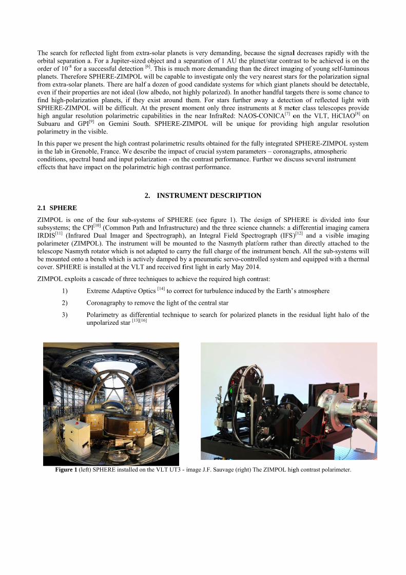
SPHERE (Spectro-Polarimetric High-contrast Exoplanet Research) is a new instrument for the VLT aimed at the direct detection of exo-planets. It has received its first light in May 2014. ZIMPOL (Zurich Imaging Polarimeter) is the imaging polarimeter subsystem of the SPHERE instrument. It's capable of both high accuracy and high sensitivity polarimetry but can also be used as a classical imager. It is located behind an extreme AO system and a stellar coronagraph. ZIMPOL operates at visible wavelengths (600-900 nm) which is best suited to detect the very faint reflected and hence polarized visible light from extra solar planets. It has an instantaneous Field of View of 3 x 3 arcsec2 (extendable to 8 arcsec diameter) with an angular resolution of 14 mili-arcsec. We discuss the results that are obtained from the full SPHERE-ZIMPOL system testing. In particular the optical, polarimetric and high contrast performance. Keywords: SPHERE, ZIMPOL, High Contrast, Exo Planets, Polarimetry, Adaptive Optics, Coronagraphy
1. INTRODUCTION
SPHERE-ZIMPOL[1][2][3] (Spectro-Polarimetric High Contrast Exoplanet Research - Zurich Imaging Polarimeter) is one of the first instruments which aim for the direct detection of reflected light from extra-solar planets. The instrument will search for direct light from old planets with orbital periods of a few months to a few years as we know them from our solar system. These are planets which are in or close to the habitable zone.
The reflected radiation is generally polarized [4][5] and the degree of polarization may be particularly high at short wavelengths < 1μm due to Rayleigh scattering by molecules and scattering by haze particles in planetary atmospheres. For this reason the visual-red spectral region is well suited for planet polarimetry.
*[email protected]; phone +31-(0)521-595172
The search foorbital separaorder of 10-8 planets. Therefrom extra-soeven if their pfind high-polSPHERE-ZIMhigh angular Subuaru andpolarimetry in
In this paper win the lab in Gconditions, speffects that ha
2.1 SPHERE
ZIMPOL is subsystems; tIRDIS[11] (Inpolarimeter (telescope Nasbe mounted ocover. SPHER
ZIMPOL exp
1)
2)
3)
Figure
or reflected ligation a. For a for a successfefore SPHER
olar planets. Tproperties are larization planMPOL will be
resolution pod GPI[9] on Gn the visible.
we present theGrenoble, Franpectral band aave impact on
E
one of the fothe CPI[10] (Co
nfrared Dual (ZIMPOL). Thsmyth rotator onto a bench wRE is installed
ploits a cascad
Extreme
Coronag
Polarimeunpolariz
1 (left) SPHER
ght from extrJupiter-sized
ful detection [
RE-ZIMPOL wThere are half
not ideal (lownets, if they e difficult. Atolarimetric caGemini South
e high contrasnce. We descr
and input polarn the polarime
2
four sub-systeommon Path Imager and She instrumentwhich is not
which is actived at the VLT a
de of three tech
Adaptive Opt
raphy to remo
etry as differezed star [13][16]
RE installed on
a-solar planetobject and a 6]. This is muc
will be capablea dozen of go
w albedo, not hexist around
t the present mapabilities in th. SPHERE-Z
st polarimetricribe the impacrization - on thtric high contr
2. INSTRU
ems of SPHEand InfrastrucSpectrograph)t will be mouadapted to carely damped byand received f
hniques to ach
tics [14] to corr
ove the light o
ential techniqu
the VLT UT3 -
ts is very demseparation of ch more demae to investigatood candidatehighly polarizthem. For st
moment only the near InfraZIMPOL wil
c results obtainct of crucial syhe contrast pe
trast performan
UMENT DE
ERE (see figucture) and the), an Integralunted to the Nrry the full chy a pneumaticfirst light in ea
hieve the requ
rect for turbul
of the central s
ue to search f
- image J.F. Sau
manding, becau1 AU the pla
anding than thte only the ver systems for w
zed). In anothetars further athree instrum
aRed: NAOSll be unique
ned for the fuystem parameterformance. Funce.
SCRIPTION
ure 1). The d three sciencel Field SpectrNasmyth platfharge of the inc servo-controarly May 2014
uired high con
lence induced
star
for polarized
uvage (right) Th
use the signalanet/star contrahe direct imagry nearest starwhich giant pler handful targway a detect
ments at 8 met-CONICA[7] ofor providin
lly integrated ters – coronagurther we disc
N
design of SPHe channels: a drograph (IFS)form rather thstrument benc
olled system a4.
trast:
by the Earth’
planets in the
he ZIMPOL hig
l decreases rarast to be achiging of young rs for the polalanets should gets there is sotion of reflectter class teleson the VLT,
ng high angu
SPHERE-ZIMgraphs, atmospcuss several in
HERE is dividifferential im)[12] and a vihan directly ach. All the sub
and equipped w
s atmosphere
e residual lig
gh contrast pola
apidly with theieved is on theself-luminous
arization signabe detectableome chance toted light withcopes provideHiCIAO[8] on
ular resolution
MPOL systempheric nstrument
ided into foumaging cameraisible imagingattached to theb-systems wilwith a therma
ht halo of the
arimeter.
e e s
al e, o h e n n
m
r a g e ll al
e
2.2 Coronagraphs
The basic concept of the ZIMPOL coronagraph is a combination of a set of broad band classical Lyot coronagraphs and two monochromatic Four Quadrant Phase Masks[15] (4QPM) which provide a smaller inner working angle. The inner working angles of the 3 λ/D and 5 λ/D Lyot coronagraphs are at 47 and 78 mas respectively. The Lyot Coronagraph mask radii are specified at 600 nm. The inner working angle of the 4QPM masks are expected to be around 20 mas.
The 5 λ/D Lyot mask in combination with broad band filters is foreseen to be the ZIMPOL main work horse for the initial planet detection given its robustness and photon collecting power. However, the planet contrast will improve rapidly with smaller star-planet separation and hence for follow up observation the coronagraphs with smaller working angle will be highly beneficial.
Table 1 SPHERE-ZIMPOL coronagraph configurations that have been used for our tests
Mask (ID) Suspension Field Stop Lyot Stop Transmission (ID) Lyot 3λ/D (CLC2) Substrate 1 x 1 asec2 56 % (STOP2) Lyot 5λ/D (CLC5) Suspended 1 x 1 asec2 78 % (STOP1)
4Quadrant Phase Mask at 656 nm (4QPM1) Substrate 8 arcsec diameter 73 % (STOP3) 4Quadrant Phase Mask at 820 nm (4QPM2) Substrate 8 arcsec diameter 73 % (STOP3)
2.3 Spectral filters
ZIMPOL is equipped with several filter wheels: one common wheel and two non-common wheels in each arm. Among many other filters the common wheel contains several Neutral Density (ND) filters to control the flux levels. The ND-filters can be combined with the transmission filters in the non-common wheels. For our tests we have used the V (550/80), NR (655/60), NI (820/80) and VBB (750/290) filters where the numbers in brackets express the filter Central Wavelength/Bandwidth in nm.
2.4 Single Difference – FLC switch
The basic ZIMPOL principle [17] for high-precision polarization measurements includes a fast polarization modulator with a modulation frequency in the kHz range, combined with a CCD [17][18] detector which demodulates the intensity signal in synchronism with the polarization modulation. The modulation frequency is much faster than the seeing variations and therefore ZIMPOL is able to capture two subsequent images with nearly identical turbulent phase screens. The polarization modulator and associated polarizer convert the degree-of-polarization signal into a fractional modulation of the intensity signal which is then measured in a demodulating detector system by a differential intensity measurement between the two modulator states. Each active pixel measures both the high and the low states of the intensity modulation and dividing the differential signal by the average signal eliminates essentially all gain changes, notably changes of atmospheric transparency or electronic gain drifts.
2.5 Double Difference – HWP2 switch
By rotating a half-wave plate (HWP2) far upstream in the optical path by 45◦, the sign of the incoming Stokes Q polarization is reversed. The instrumental aberrations, on the other hand, remain unchanged, resulting in the same background landscape as before. If the polarization images before and after the signal switching are subtracted from one another, the real polarization signals of the astronomical target add up constructively while the static background is canceled out.

2.6 Turbulence Simulator
A turbulence simulator is located at the optical entrance of the SPHERE bench. The turbulence is generated by a rotating phase screen [20]. For our tests we have used typical conditions of 0.85 arcsec seeing and 12.5 m/s windspeed that correspond to the ‘normal’ conditions that are foreseen at the VLT. The turbulence simulator is fed by a high energetic broad band source (Energetiq LDLS EQ-99FLC). This source produces a reasonable flat spectrum over the 500 – 790 nm band and has peaks at 820 and 880 nm.
2.7 Instrument Polarization
To achieve high contrast performance the polarized input signal at the ZIMPOL detectors must be lower than about 1%. Therefore we have characterized the polarimetric behaviour of the turbulence simulator and the SPHERE optical bench [21]. The polarization Q/I measured at the ZIMPOL detectors is a combination of polarization introduced before HWP2 (the Turbulence Simulator and mirror M4) and polarization introduced after HWP2 (the SPHERE optical components – in particular the derotator). To minimize the input polarization at the ZIMPOL detectors we have used a twofold strategy: 1) to minimize the input polarization introduced before HWP2 the HWP2 rotation is set at a Q/I zero crossing. The subsequent 45 degree HWP2 switch will also be at a zero crossing and 2) to minimize the input polarization introduced after HWP2 we have used the ZIMPOL internal Polarization Compensator.
3. DATA REDUCTION
The basic data reduction steps [24] are as follows. Bias is subtracted based on the pre –and overscan regions of the individual frames. The data is split in two datasets corresponding to the two HWP2 settings of the DD measurement. Each dataset is split up in sets of two consecutive frames and these sets are converted to Stokes Q taken into account the ZIMPOL CCD double phase mode operation. The Q frames are averaged and the end results are two final frames where each frame corresponds to a SD measurement. The two averaged SD frames are subtracted and divided by two to yield the final DD Stokes Q frame. An identical procedure is applied where the sets of two consecutive frames are converted to Stokes I taken into account the ZIMPOL double phase mode operation. This will yield the final DD Stokes I frame. From these two final DD frames it’s obvious to obtain the overall normalized Stokes Q/I frame. The contrast is estimated from the noise level in the final averaged images. We will present our results as plots of azimuthal statistics as function of radial separation from the PSF peak. The azimuthal statistics are calculated over a ring with the width of a resolution element λ/D, i.e. 3 pixels.
4. PERFORMANCE MODELING
The ZIMPOL performance simulations are done with the CAOS [22] problem solving environment and are extensively described in Thalmann[23]. The model data that we present in this study is obtained with the same simulation code. Both the CAOS model data and the experimental data is processed by the same data reduction software to produce the standard contrast curves as shown in Figure 2. This figure is obtained with input parameters according to Standard Case 4 (SC4) as described by Thalmann[23] unless specified otherwise. We have used an integration time of about 1 hour to match the photon noise with our experimental data. The simulation of Figure 1 matches with our standard experimental test case:
- Coronagraph: Classical Lyot 5 λ/D - Filter: NR - Atmospheric conditions: Seeing 0.85 arcsec and wind speed 12.5 m/s - Incoming polarization: Minimized
The results as of Figure 2 shown a standard diagram with the azimuthally averaged PSF Intensity signal or the rms-noise calculated for the corresponding azimuthal ring. The graphs include from the top to bottom:
- The azimuthally averaged non-coronagraphic PSF normalized to the peak signal. The azimuthal average is the mean of a ring with a width of a resolution element λ/D.

- The Aver
- The noissign
- The
Figure 2 SimCase4 (ThalmaHWP2 at 00 an
This section results of a sparameter. Tpolarization.
5.1 Standar
The standard
- Coro- Filte- Atm- Inco
The results of
azimuthally raging is donerms-noise le
e for HWP2 pals. photon noise
mulated contrastann[23]). Curvesnd 45 deg, Doub
5.
describes the standard test cThe parameter
Each test take
d test case
setup for the
onagraph: er:
mospheric condoming polariza
f the standard
averaged core as above. vel for the dposition 0 deg
limit.
t curves from ths from top to boble Difference
HIGH CO
high contrastcase. Subsequrs under invees about 30 mi
high contrast
Clas NR
ditions: Seeiation: Min
test case are d
onagraphic P
ifferential polgrees and 45 d
he CAOS modottom: non-coropolarization, ph
ONTRAST P
t performanceuently we inveestigation are inutes and inc
tests is:
ssical Lyot 5 λ
ing 0.85 arcsenimized
displayed in F
PSF normalize
larization signdegrees and th
del output of thonagraphic profhoton noise lim
PERFORMA
e measuremenestigate the im
spectral filtecludes of the o
λ/D
ec and wind sp
Figure 3 and th
ed to the peak
nal. It is disthe double diff
he standard test file, coronagrap
mit. Confidence
ANCE MEA
nts done for Smpact on the ers, coronagraorder of 1000
peed 12.5 m/s
he contrast cu
k signal of th
inguished betference noise
case using thehic profile, Sinlevel 1-sigma.
ASUREMEN
SPHERE-ZIMstandard test aphs, atmosphframes.
rves are show
he non-corona
tween the sinwhen combin
e input parametngle Difference
NTS
MPOL. First wcase if we chheric conditio
wn in Figure 4
agraphic PSF
ngle-differencening these two
ters of Standardpolarization fo
we describe thehange a singleons and inpu
.
F.
e o
d r
e e
ut
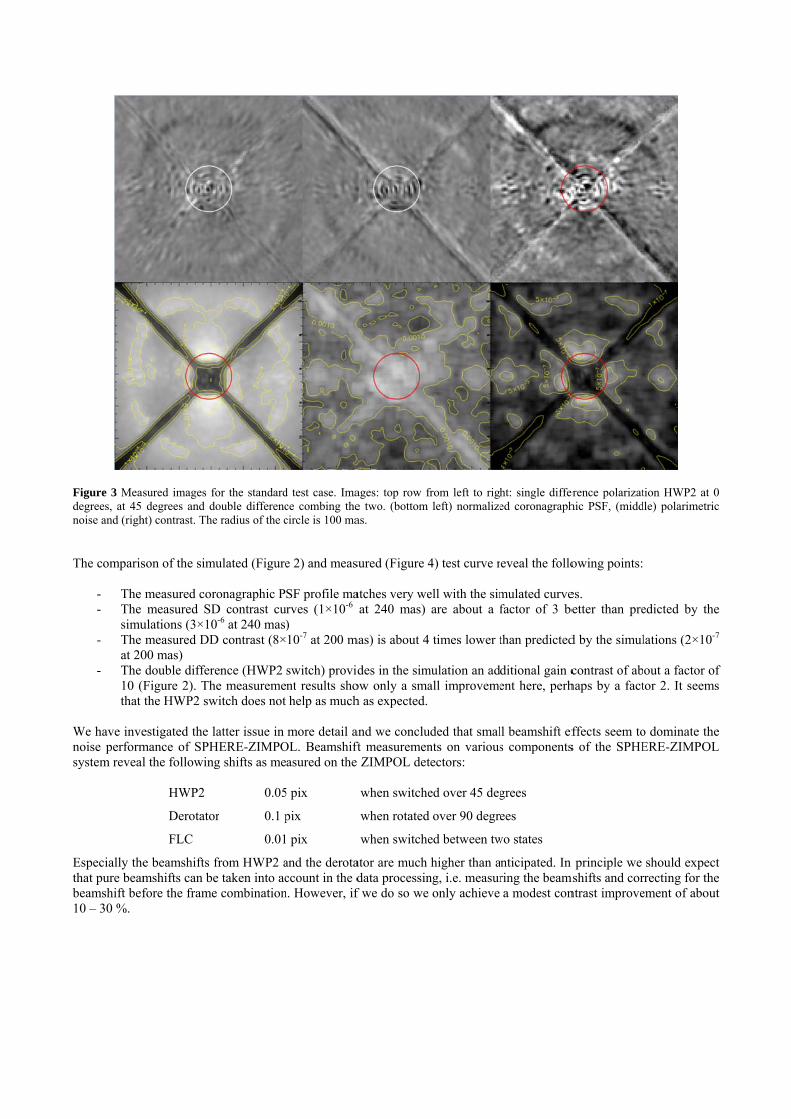
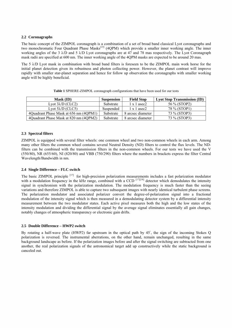
Figure 3 Measdegrees, at 45 noise and (righ
The comparis
- The - The
simu- The
at 20- The
10 (Fthat
We have invenoise performsystem reveal
Especially thethat pure beambeamshift bef10 – 30 %.
sured images fdegrees and d
ht) contrast. The
son of the sim
measured cormeasured SD
ulations (3×10measured DD
00 mas) double differFigure 2). Ththe HWP2 sw
estigated the lmance of SPHl the following
HWP2
Derotato
FLC
e beamshifts fmshifts can before the frame
for the standarddouble difference radius of the c
mulated (Figure
ronagraphic PD contrast cu0-6 at 240 mas)D contrast (8×
ence (HWP2 he measuremewitch does not
latter issue in HERE-ZIMPOg shifts as me
0.05
or 0.1 p
0.01
from HWP2 ae taken into ace combination
d test case. Imace combing thecircle is 100 ma
e 2) and meas
SF profile maurves (1×10⁻⁶
) 10-7 at 200 m
switch) providnt results shohelp as much
more detail aOL. Beamshiftasured on the
5 pix
pix
pix
and the derotaccount in the d
n. However, if
ages: top row fe two. (bottom as.
sured (Figure 4
atches very weat 240 mas)
mas) is about 4
des in the simow only a smah as expected.
and we concluft measuremen ZIMPOL det
when switche
when rotated
when switche
ator are much data processinf we do so we
from left to righleft) normalize
4) test curve r
ell with the simare about a f
times lower t
mulation an adall improveme
uded that smalnts on varioustectors:
ed over 45 deg
d over 90 degre
ed between tw
higher than ang, i.e. measur
only achieve
ht: single differed coronagraph
eveal the follo
mulated curvefactor of 3 be
than predicted
ditional gain cent here, perh
ll beamshift efs components
grees
ees
wo states
nticipated. In ring the beama modest con
erence polarizathic PSF, (midd
owing points:
es. etter than pre
d by the simul
contrast of abhaps by a fact
ffects seem tos of the SPHE
principle we mshifts and corntrast improve
tion HWP2 at 0dle) polarimetric
edicted by the
lations (2×10-
out a factor otor 2. It seems
o dominate theERE-ZIMPOL
should expecrrecting for theement of abou
0 c
e
7
f s
e L
ct e
ut

Figure 4 Measprofile, Single level 1-sigma.
To find a betparameters oparameters aswave front er
The resultingZIMPOL diffreduces the g
sured contrast cDifference pol
tter corresponf the CAOS s listed in Tabrrors.
ZI
ZIM
g simulation isferential aberrain in DD per
curves for the larization for H
ndence betweemodel and keble 2 only ha
Table 2 In
CPI differen
IM phase diff
M pointing dif
ZIM beam
s shown in Figration the SD rformance.
standard test caHWP2 at 00 an
en the measurept the rest o
ave impact on
nput parameter
ntial beam shi
ferential aberra
fferential aber
mshift effect (
gure 5 and weperformance i
ase. Curves frond 45 deg, Dou
rements and tof the input pn the pre-coron
rs for the CAOS
ift (nm)
ation (nm)
rration (nm)
(nm)
e conclude a gis improved w
om top to bottouble Difference
the simulationarameters as nagraph diffe
S performance s
Standard Cas
0
0.75
0.75
0.75
good match wwhereas the in
m: non-coronagpolarization, p
ns we have adof the Standarential and po
simulation.
se4 Adjuste
30
0.25
0
0
ith Figure 4. Wncrease of the
agraphic profilephoton noise lim
djusted two grard Case4[23].ost coronagrap
ed to
5
We see that byCPI different
e, coronagraphicmit. Confidence
roups of inpu The adjustedph differentia
y reducing theial aberrations
c e
ut d al
e s

We must remthe simulationto Δw = Δx/aberration aninput parameZIMPOL per
Figure 5 SimuCase4 with adjSingle Differensigma.
5.2 Spectral
Measurementplots for the s As expected ta radius beyothe same timeperformance obtain for filt That polarimepolarization i
mark that in thns with the m(2F) where F
nd at about 15eters. Therefoformance deg
ulated contrast djusted input pance polarization
l filters
ts as of the stashorter wavele
the AO and coond 120 mas we the differentis comparableters, V, NR, an
etry works beimages in Figu
he current stagmeasurements. F = 221 the F5 nm for the Core we conclugradation.
curves from tharameters as of n for HWP2 at
andard test casength in the V
oronagraphic pwhere the corotial polarimetre for the two wnd NI the sam
tter at short wure 7. The ima
ge the adjusteIf we convert-number at th
CPI differentiaude that othe
he CAOS modef Table 2 . Curvt 00 and 45 deg
se but for diffeV filter and in t
performance ionagraphic perry works bettewavelengths. W
me limit of 4×1
wavelength is aages show tha
ed numbers cart the measurehe ZIMPOL dal aberration, er mechanism
el output of theves from top tog, Double Diffe
ferent color filthe longer wa
is better for lorformance is aer at short wavWe have meas10-7.
an interesting at the NI-band
an only be cond beamshifts detector we ai.e. values th
ms then pure
e standard test o bottom: non-erence polariza
lters were carravelength in th
onger wavelenabout a factor velengths so thsured the cont
result and is id differential p
nsidered as ‘f(Δx) to wavefrrive at 1.5 n
hat differ signidifferential a
case using the coronagraphic
ation, photon no
ried out. Figurhe NI filter.
ngth. This is paof 3 better in
hat in the end trast at a separ
illustrated by tpolarization sig
fitting’ paramfront errors (Δ
nm for the ZIificantly from
aberrations ar
e input parametprofile, coronaoise limit. Con
re 6 shows the
articularly wethe I-band. Hthe overall coration of 240
the Double Dgnal is much m
eters to matchΔw) accordingM differentia
m the adjustedre causing the
ters of Standardagraphic profilefidence level 1
e contrast
ell visible for However, at ontrast mas and
ifference more affected
h g al d e
d e, -
d
by residual spcompensated
Figure 6 CompCurves from todeg, Double D
Figure 7 Meas
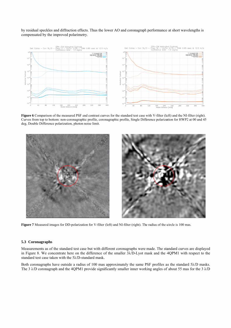
5.3 Coronag
Measurementin Figure 8. Wstandard test
Both coronagThe 3 λ/D cor
peckles and diby the improv
parison of the mop to bottom: noifference polari
sured images fo
graphs
ts as of the staWe concentracase taken wi
graphs have oronagraph and
iffraction effeved polarimet
measured PSF aon-coronagraphization, photon
or DD-polarizat
andard test caate here on thth the 5λ/D-st
utside a radiud the 4QPM1
cts. Thus the ltry.
and contrast curhic profile, coronoise limit.
ion for V-filter
se but with die difference otandard mask.
us of 100 masprovide signi
lower AO and
rves for the stanonagraphic prof
(left) and NI-fi
ifferent coronaof the smaller.
s approximateificantly small
d coronagraph
ndard test case wfile, Single Diff
filter (right). Th
agraphs were r 3λ/D-Lyot m
ly the same Pler inner work
h performance
with V-filter (leference polariza
e radius of the c
made. The stamask and the 4
PSF profiles aking angles of
e at short wave
eft) and the NI-ation for HWP2
circle is 100 ma
andard curves4QPM1 with
as the standardf about 55 mas
elengths is
filter (right). 2 at 00 and 45
as.
s are displayedrespect to the
d 5λ/D maskss for the 3 λ/D
d e
s. D

mask and as 4QPM1 in thdetector satur
To investigat4QPM2 coropolarization ipolarized ringcauses relativmost favorabl
Figure 8 Compto bottom: nonDifference pola
Figure 9 Measat 45 degrees aPSF core. This
5.4 Atmosph
Measurementthe turbulenc
low as perhaphe center is oration.
e the residual onagraph in thimages obtaing pattern. Un
vely high noisle.
parison of the Pn-coronagraphiarization, photo
sured polarizatiand double diffs ring pattern do
heric conditio
ts as of the stae simulator fo
ps 25 mas fornly about 30
speckle and dhe NI-band. Wned with the 4nfortunately we levels. This
PSF and contrasc profile, coro
on noise limit.
on images for 4ference combinoesn’t complete
ons
andard test caor 3 different w
r the 4 QPM1times higher
diffraction effWe expect the4QPM2 in NI
we also see inis particular h
st curves for thenagraphic prof
4QOM2 with Nng the two SD iely subtract out
ase but for difwind speeds.
1 (IWA for thr than at 100
fects close to tese effects toI-band are shon the figure thharmful close
e 3λ/D mask (lefile, Single Dif
NI-filter from leimages. In the as can be seen
fferent atmospThey represen
he 5 λ/D maskmas and this
the PSF core i be most proown in Figurhat this patterto the PSF co
eft) and the 4Qfference polariz
ft to right: singltwo SD imagein the DD-imag
pheric conditint, besides the
k is about 90 should not c
in more detailnounced for te 9. In the SDrn also survivore where pola
PM1 (right) in zation for HWP
le difference pos we see a polage. The radius o
ons were made average cond
mas). The pecause severe p
l we have donthis case. TheD images we ves the DD-suarimetric plan
the NR band. CP2 at 00 and 4
olarization HWarized ring pattof the circle is 1
de. We carriedndition with a
eak flux of theproblems with
ne test with thee SD and DDsee a distinc
ubtraction andnet detection is
Curves from top45 deg, Double
P2 at 0 degreestern close to the100 mas.
d out test withseeing of 0.85
e h
e D ct d s
p e
s, e
h 5
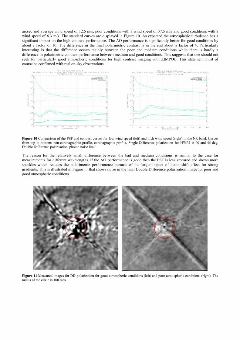
arcsec and avwind speed osignifcant imabout a factointeresting isdifference in seek for partcourse be con
Figure 10 Comfrom top to boDouble Differe
The reason fmeasurementspeckles whigradients. Thgood atmosph
Figure 11 Mearadius of the ci
verage wind sof 6.3 m/s. Th
mpact on the hor of 10. Thes that the difpolarimetric c
ticularly goodnfirmed with r
mparison of theottom: non-coroence polarizatio
for the relativts for differenich reduces th
his is illustrateheric conditio
asured images ircle is 100 mas
speed of 12.5 he standard cuhigh contrast pe difference infference occucontrast perfod atmosphericreal on-sky ob
e PSF and contronagraphic proon, photon noise
vely small dint wavelengthshe polarimetrd in Figure 11ns.
for DD-polarizs.
m/s, poor conurves are dispperformance. Tn the final pors mainly be
ormance betwec conditions fbservations.
rast curves for ofile, coronagrae limit.
ifference betws. If the AO pric performan1 that shows n
ation for good
nditions withplayed in FiguThe AO perfoolarimetric coetween the poeen medium afor high contr
low wind speeaphic profile, S
ween the badperformance ince because onoise in the fin
atmospheric co
a wind speedure 10. As exormance is sigontrast is in thoor and mediand good condrast imaging
d (left) and higSingle Differenc
d and mediumis good then tof the larger nal Double Di
onditions (left)
d of 37.5 m/s apected the atmgnificantly behe end about ium conditionditions. This swith ZIMPO
gh wind speed (ce polarization
m conditions the PSF is lesimpact of be
ifference pola
and poor atmos
and good conmospheric turetter for good t a factor of 4ns while thersuggests that o
OL. This state
(right) in the Nfor HWP2 at
is similar toss smeared aneam shift effearization imag
spheric conditi
nditions with arbulence has aconditions by
4. Particularlyre is hardly aone should noement must o
NR band. Curve00 and 45 deg
o the case ford shows more
fect for strongge for poor and
ons (right). The
a a y y a
ot f
s g,
r e g d
e

5.5 Input polarization
One could imagine that the performance is reduced if the overall polarization of the incoming star light is polarized by interstellar matter or the telescope. With flat field illuminations free of strong intensity gradients it was demonstrated that highest sensitivity of 10-5 could only be achieved if the polarization of the illumination was less than about 1%[24].
Measurements as of the standard test case but with different levels of input polarization were made. The limited performance of the standard test case is not caused by the polarization of the illuminating point source. We have checked this with high contrast tests inducing for the incoming light a high polarization of 3.2%. The measured double difference noise performance was not affected by this when compared to very low polarized (<0.2%) incoming light. One reason for not seeing an effect is that the polarimetric sensitivity is reduced in the high contrast tests due to the beam-shift effect acting on the speckle pattern of the PSF. Thus the effect of the polarized incoming light seems to be too small to be noticed in the high contrast data. We conclude that instrumental polarization is not critical, unless the polarimetric contrast can be further enhanced toward the previously anticipated goal value.
6. DISCUSSION
The high contrast measurement data as presented in the previous section strongly indicates that complex beamshifts effects have a strong impact on the SPHERE-ZIMPOL performance. In this section we will discuss several components that will introduce beam deviations between the two orthogonal linear polarization states in the optical path. 6.1 HWP2 beamshifts
In the SPHERE-ZIMPOL system we observe that HWP2 introduces a beamshift on the ZIMPOL CCDs of about 0.1 pixel where 1 pixel has a size of 60×60 micron. We can attribute this beamshift to a cutting error of the HWP2 crystal, i.e. the crystal is not cut exactly parallel to the crystal optical axis. The dispersion angle α between the e –and o-beam is then given by
tantan ∆
∆
where Δθ is the cutting error and ne = 1.55051 and no = 1.54148 for Crystal Quartz at 670 nm. In the SPHERE-ZIMPOL optical system HWP2 is located 187 mm from the F/15 VLT input focal plane. The focal ratio of the camera lens on the ZIMPOL CCD is F/221. An angular beam deviation at the location of HWP2 will hence be magnified as a beam displacement on the ZIMPOL CCD by a factor of 187×(221/15) = 2755.
We calculate that a beamshift of 0.1 pixel is caused by a cutting error of only 0.01 deg (36 asec). From a manufacturing point of view this seems like an excellent achievement. However, the location of HWP2 in the SPHERE optical setup magnifies the beam deviation by a factor of 2755.
6.2 FLC beamshifts
In the SPHERE-ZIMPOL system we observe that the FLC introduces a beamshift at the ZIMPOL CCDs of about 0.01 pixel where 1 pixel has a size of 60×60 micron. The FLC consists of a thin layer of liquid crystals confined between two relatively thick and stiff fused silica substrates. Small glass spheres are used as spacers between the substrates to achieve a gap of about 3 micron thickness. We assume that the beamshift is caused by a small wedge angle in the liquid crystal gap. To estimate the wedge angle we proceed as follows.
The beamshift of 0.01 pixel on the ZIMPOL CCD corresponds to about 1 micron. The FLC is located in a collimated beam just in front of the ZIMPOL camera lens with a focal length of about 1400 mm. Therefore the angular beam deviation introduced by the FLC will be about (1×10⁻³)/1400 = 7×10⁻⁷ radians and the wedge angle γ = (7×10⁻⁷)/Δn = 6.5×10⁻⁶ radians ~ 1 arcsec. The FLC diameter is about 25 mm and so the error in the spherical spacers is in the order of 25 × 6.5×10-6 ~ 0.15 micron.

From a manusystem the sm
6.3 Polarize
Fabry Perot[2
Figure 9 and
The FLC consubstrate platcoating is relFP etalon. Mchange in the
The PSF can and odd transhence ring shFigure 12.
Figure 12 (rigpolarization sig
An FP-etalonmight have ieffects are soto differentiaboth SD imagnot the main c
6.4 Metallic
The observedreflection. SuImbert-FederHanchen beamof incidence.polarization a
ufacturing poinmall differenti
ed ring struct26](FP) effectshence a residu
ntains a (very tes are coatedatively high c
Moreover, swite FP transmiss
be calculated smission profihaped residual
ght) Fabry Pergnal
n might be senimpact on FP small that the
al optical pathges is nearly scause of the p
c mirror beam
d beamshifts uch deviationrov[28] (IF) effm deviations In the conte
and therefore w
nt of view thial tilt will be l
ure
s in the FLC[2
ual noise patte
accurate) pard with an ITOcompared to stching of the sion profile (se
as an integraliles. This givels will show u
rot effects in t
nsitive to the P output patteey can’t give r
h lengths ordesimilar and w
performance d
mshifts
for the derotns are classififect for a circoccur in the p
ext of SPHERwe will only c
is seems a verlevered by a f
25] can cause ern.
rallel gap betwO (Indium Tin
tandard anti-rFLC will chaee Figure 12).
l over the speces slightly diffup in the polar
the FLC transm
angle of incidrn and therebrise to differenrs of magnitu
will subtract indegradation.
tator are attried as Goos-Hcular polarizeplane of incideRE-ZIMPOL bconcentrate on
ry good achievfactor of 1400
a residual rin
ween two subsn Oxide) coatireflection coatange the index.
ctral band of aferent PSFe anarized image g
mission profile
dence. This mby on the polnces in the twude smaller thn the DD. Sinc
ibuted to the Hanchen[27] (Gd input beamence whereas beam deviation the Goos-Ha
vement. Howto show up a
ng structure in
strate filled wing to serve atings. The FLx of refraction
a mono-chromnd PSFo profigiven by (PSF
es for the two
means that bealarization patt
wo SD images,han the wavelce this is not
small spatiaGH) effect fo
m (see Figure the Imbert-Feons to first oanchen effect.
ever, we see ts a beamshift
n the polariza
with liquid cryas electrodes. C gap and refn of the gap a
matic Airy pattiles for the tw
Fe-PSFo)/(PSF
FLC switchin
am shift effecttern. Howeve, i.e. the tilt anlength. In othethe case we c
l and angularor a linear po
13 copied froederov deviatirder we are o
that in the ZIMon the ZIMPO
ation signal a
ystals. The insThe reflectanflective ITO cand will there
tern weightedwo FLC switchFe+PSFo) as c
ng states (righ
cts that are cauer, the observngles in the FLer words, theconclude that
r deviations olarized input om Merano[30
ions are normonly concerne
MPOL opticaOL CCDs.
as observed in
ide of the twonce of the ITOcoatings act asefore induce a
d with the evenhing states andcan be seen in
t) Residual SD
used upstreamed beam shifLC cavity lead
FP pattern inFP effects are
from specularbeam and as
0]). The Goosal to the planeed with linear
al
n
o O s a
n d n
D
m ft d n e
r s -e r
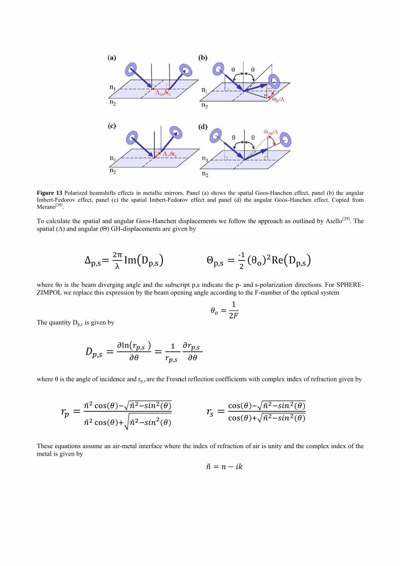
Figure 13 PolImbert-FedorovMerano[30].
To calculate tspatial (Δ) an
where θo is tZIMPOL we
The quantity
where θ is the
These equatiometal is given
larized beamshiv effect, panel
the spatial annd angular (Θ)
∆ ,
the beam divereplace this e
Dp,s is given b
,
e angle of inci
ons assume ann by
ifts effects in ml (c) the spatia
d angular Goo) GH-displace
Im D
erging angle axpression by t
by
,
idence and rp,s
n air-metal int
metallic mirrorsal Imbert-Fedor
os-Hanchen dments are giv
D ,
and the subscrthe beam open
,
s are the Fresn
terface where
s. Panel (a) shorov effect and
displacements ven by
Θ
ript p,s indicaning angle acc
,
nel reflection c
the index of
ows the spatialpanel (d) the
we follow th
,‐ θ
ate the p- andcording to the
12
coefficients w
refraction of
Goos-Hanchenangular Goos-
e approach as
θ Re D
s-polarization F-number of
ith complex in
air is unity an
n effect, panel -Hanchen effec
s outlined by
D ,
n directions. Ff the optical sy
ndex of refrac
nd the comple
(b) the angulact. Copied from
Aiello[29]. The
For SPHEREystem
ction given by
ex index of the
ar m
e
-
y
e

For a first esaccording to
where pix = ratio of F-numderotator to th
It seems that overall beamsvalues. The pcomplex than
Figure 14 Esti
stimate we ass
60 micron, thmbers at the Zhe F/15 VLT-
the calculatedshift of 0.1 piprobable caus
n can be descri
imated beam sh
sume a silver
he factor of 2 ZIMPOL cam-focus. The res
d values for thixels. Howevese for this deibed by the w
hifts at the ZIMP
coating for th
_
_
comes from tmera and the de
sults are show
he spatial beaer, the model peviation is thaavelength dep
POL detector as
the optics. We
21
21
two derotatorerotator, L =
wn in Figure 1
amshift correspredicts anguat the he layependent index
s caused by the
e trace the be
22115
∆
1 22115
r mirrors at 55350 mm whic4.
spond very reaular beamshiftered structure of refraction
e Goos-Hanchen
am deviations
∆
5 deg angle och is about the
asonable withs that are mucof the derota
of silver.
n spatial (red) a
ns to the ZIMP
of incidence, (e average dist
h the measuredch larger thantator coating i
and angular (blu
POL detectors
(221/15) is thetance from the
d values of ann the measuredis much more
ue) deviations.
s
e e
n d e
6.5 Future work
Currently we are working on a system model that assumes that what we see on the detector is not pure beamshift effect. Some components (HWP2, derotator, FLC) will split the unpolarized input beam in orthogonal polarized sub-beams. Components further downstream will again split a single sub-beam in two other sub-sub beams. So on the detector we see some superposition of sub-beams where each sub-beam is slightly displaced w.r.t. the other sub-beams and each sub-beam might have different amplitude then the other sub-beams. In general the first element splits the beam in two sub-beams, the second element splits the beam in four sub-beams, the third element splits the beam in eight sub-beams, etc. This would also explain why correcting for the beam shift only gives rather modest performance improvement. We assume that unpolarized input beam splits in many sub-beams and that the residual noise pattern is caused by superposition of sub-beams. We are working on component and system improvements and will use the model to quantify the impact on high contrast performance.
7. CONCLUSIONS
The SPHERE-ZIMPOL high contrast tests carried out in September 2013 at IPAG, Grenoble, France give a good assessment of the polarimetric contrast performance of ZIMPOL including the AO and coronagraph performance. We have demonstrated with realistic system tests that ZIMPOL reaches a contrast better than 10-6 using the foreseen polarimetric double-difference technique. This is at least one order of magnitude better than any previous high contrast polarimetry published today. However, the performance is about a factor four less good than expected because of unforeseen instrumental effects. Of particular interest is that the polarimetric performance is better if the AO performance is less good and vice versa. Speckle subtraction by polarimetry suffers mainly by the beam shift effects that are currently under investigation. Improvements in the correction or calibration of the beam shift effect will in particular help to push the performance for observations taken under very good AO conditions, long wavelengths and good seeing because these observations are most affected by the residual speckle pattern. Using angular differential imaging techniques [31] at the telescope it should be possible to push the polarimetric contrast limits towards 1×10⁻⁷ which would be reachable from day one. It is not excluded that improved data reduction based on further analysis of the instrument, upgrades of individual components, or more sophisticated observing strategies can provide in the near future the goal performance contrast of 10-8 for SPHERE-ZIMPOL. However it seems now too optimistic to hope for such a performance already during the first year(s) of operation of the instrument.
REFERENCES
[1] Schmid, H. M., Beuzit, J.-L., Feldt, M., Gisler, D., Gratton, R., Henning, T., Joos, F., Kasper, M., Lenzen, R., Mouillet, D., Moutou, C., Quirrenbach, A., Stam, D. M., Thalmann, C., Tinbergen, J., Verinaud, C., Waters, R., and Wolstencroft, R., “Search and investigation of extra-solar planets with polarimetry,” IAU Colloq. 200, 165–170 (2006)
[2] D. Gisler, H.M. Schmid, C. Thalmann, H.P. Povel, J.O. Stenflo, F. Joos, M. Feldt, R. Lenzen, J. Tinbergen, R. Gratton, R. Stuik, D.M. Stam, W. Brandner, S. Hippler, M. Turatto, R. Neuhäuser, C. Dominik, A. Hatzes, Th. Henning, J. Lima, A. Quirrenbach, L.B.F.M. Waters, G. Wuchterl, H. Zinnecker, “CHEOPS/ZIMPOL: a VLT instrument study for the polarimetric search of scattered light from extrasolar planets,” Proc. SPIE 5492, 463-474 (2004)
[3] Beuzit, J.-L., Feldt, M., Dohlen, K., Mouillet, D., Puget, P., Antichi, J., Baruffolo, A., Baudoz, P., Berton, A., Boccaletti, A., Carbillet, M., Charton, J., Claudi, R., Downing, M., Feautrier, P., Fedrigo, E., Fusco, T., Gratton, R., Hubin, N., Kasper, M., Langlois, M., Moutou, C., Mugnier, L., Pragt, J., Rabou, P., Saisse, M., Schmid, H. M., Stadler, E., Turrato, M., Udry, S., Waters, R., and Wildi, F., “SPHERE: A ‘Planet Finder’ Instrument for the VLT,” The Messenger 125, 29–34 (2006)
[4] D. M. Stam, “Spectropolarimetric signatures of Earth-like extrasolar planets,” A&A 482, 989-1007 (2008)
[5] E. Buenzli, H.M. Schmid, “A grid of polarization models for Rayleigh scattering planetary atmospheres,” Astron. Astrophys. 504, 259-276 (2009)
[6] Julien Milli, David Mouillet, Dimitri Mawet, Hans Martin Schmid, Andreas Bazzon, Julien H. Girard, Kjetil Dohlen, Ronald Roelfsema, “Prospects of detecting the polarimetric signature of the Earth-mass planet alpha Centauri B b with SPHERE / ZIMPOL,” A&A, (2013)
[7] Sascha P. Quanz, Hans Martin Schmid, Kerstin Geissler, Michael R. Meyer, Thomas Henning, Wolfgang Brandner, Sebastian Wolf, “VLT/NACO Polarimetric Differential Imaging of HD100546 - Disk Structure and Dust Grain Properties between 10-140 AU,” ApJ, 738 Issue 1, 23 (2011)
[8] Michihiro Takami et al, “High-Contrast Near-Infrared Imaging Polarimetry of the Protoplanetary Disk around RY Tau,” ApJ 772, Issue 2, 145 (2013)
[9] Macintosh, B., Graham, J. R., Ingraham, P. et al, “The Gemini Planet Imager: First Light,” ArXiv e-prints 1403.7520 (2014)
[10] Jean-François Sauvage, Jean-Luc Beuzit, Ronald roelfsema, et al., "Sphere: complete laboratory performance and prediction for on-sky first light", Proceedings of SPIE Vol. 8864, 88640B (2013)
[11] Kjetil Dohlen , Michel Saisse et al, “Manufacturing and integration of the IRDIS dual imaging camera and spectrograph for SPHERE,” Proc. SPIE 7735, (2010)
[12] Ricardo Claudi, “SPHERE IFS: The spectro differential imager of the VLT for exoplanets search,” Proc. SPIE 7735, (2010)
[13] Franco Joos, Esther Buenzli, Hans Martin Schmid and Christian Thalmann, “Reduction of polarimetric data using Mueller calculus applied to Nasmyth instruments,“ Proc. SPIE 7016, (2008)
[14] C. Petit , J.-F. Sauvage , A. Sevin ; A. Costille , T. Fusco , P. Baudoz , J.-L. Beuzit , T. Buey , J. Charton , K. Dohlen , P. Feautrier , E. Fedrigo , J.-L. Gach , N. Hubin , E. Hugot , M. Kasper , D. Mouillet , D. Perret , P. Puget , J.-C. Sinquin , C. Soenke , M. Suarez , F. Wildi, “The SPHERE XAO system SAXO: integration, test, and laboratory performance,” Proc. SPIE 8447, (2012)
[15] Rouan, D., Riaud, P., Boccaletti, A., Cl´enet, Y., and Labeyrie, A., “The Four-Quadrant Phase-MaskCoronagraph. I. Principle,” The Publications of the Astronomical Society of the Pacific 112, 1479–1486 (2000)
[16] Quanz, Sascha P.; Meyer, Michael R.; Kenworthy, Matthew A.; Girard, Julien H. V.; Kasper, Markus; Lagrange, Anne-Marie; Apai, Daniel; Boccaletti, Anthony; Bonnefoy, Mickaël; Chauvin, Gael; Hinz, Philip M.; Lenzen, Rainer, “First Results from Very Large Telescope NACO Apodizing Phase Plate: 4 μm Images of The Exoplanet β Pictoris b,” ApJ 722, 49 (2010)
[17] Povel, H. P., Aebersold, F., and Stenflo, J., “Charge-coupled device image sensor as a demodulator in a 2-D polarimeter with a piezoelastic modulator,” Appl. Opt. 29, 1186 (1990)
[18] Schmid, Hans-Martin; Downing, Mark; Roelfsema, Ronald; Bazzon, Andreas; Gisler, Daniel; Pragt, Johan; Cumani, Claudio; Salasnich, Bernardo; Pavlov, Alexey; Baruffolo, Andrea; Beuzit, Jean-Luc; Costille, Anne; Deiries, Sebastian; Dohlen, Kjetil; Dominik, Carsten; Elswijk, Eddy; Feldt, Markus; Kasper, Markus; Mouillet, David; Thalmann, Christian; Wildi, François, “Tests of the demodulating CCDs for the SPHERE / ZIMPOL imaging polarimeter,” Proc. SPIE 8446, (2012)
[19] P. Martinez, C. Loose, E. Aller Carpentier and M. Kasper, “Speckle temporal stability in XAO coronagraphic images,” A&A 541, A136 (2012)
[20] L. Jolissaint, “Optical Turbulence Generators for Testing Astronomical Adaptive Optics Systems: A Review and Designer Guide,” PASP 118, 1205-1224, (2006)
[21] Andreas Bazzon , Daniel Gisler , Ronald Roelfsema , Hans M. Schmid , Johan Pragt , Eddy Elswijk , Menno de Haan , Mark Downing , Bernardo Salasnich , Alexey Pavlov , Jean-Luc Beuzit , Kjetil Dohlen ,David Mouillet , François Wildi, “SPHERE / ZIMPOL: characterization of the FLC polarization modulator,” Proc. SPIE 8446, (2012)
[22] Carbillet, M., Boccaletti, A., Thalmann, C., Fusco, T., Vigan, A., Mouillet, D., and Dohlen, K., “The software package SPHERE: a numerical tool for end-to-end simulations of the VLT instrument SPHERE,” Proc. Spie 7015, (2008)
[23] Thalmann, Christian, Schmid, Hans M., Boccaletti, Anthony, Mouillet, David, Dohlen, Kjetil, Roelfsema, Ronald, Carbillet, Marcel, Gisler, Daniel, Beuzit, Jean-Luc, Feldt, Markus, Gratton, Raffaele, Joos, Franco, Keller, Christoph U., Kragt, Jan, Pragt, Johan H., Puget, Pascal, Rigal, Florence, Snik, Frans, Waters, Rens, Wildi, François, “SPHERE ZIMPOL: overview and performance simulation,” Proc. SPIE 7014, 70143F, (2008)

[24] Ronald Roelfsema , Daniel Gisler , Johan Pragt , Hans Martin Schmid , Andreas Bazzon , Carsten Dominik , Andrea Baruffolo , Jean-Luc Beuzit , Julien Charton , Kjetil Dohlen , Mark Downing , Eddy Elswijk , Markus Feldt , Menno de Haan , Norbert Hubin , Markus Kasper , Christoph Keller , Jean-Louis Lizon , David Mouillet , Alexey Pavlov , Pascal Puget , Sylvain Rochat , Bernardo Salasnich , Peter Steiner , Christian Thalmann , Rens Waters , François Wildi, “The ZIMPOL high contrast imaging polarimeter for SPHERE: sub-system test results,” Proc. SPIE 8151, (2011)
[25] M. de Juan Ovelar ; S. Diamantopoulou ; R. Roelfsema ; T. van Werkhoven ; F. Snik ; Johan Pragt and C. Keller, Proc. SPIE, 844912 (2012)
[26] D. K. Aitken and J. H. Hough, "Spectral Modulation, or Ripple, in Retardation Plates for Linear and Circular Polarization," Pub. Astron. Soc. Pacific 113, pp. 1300–1305 (2001)
[27] F. Goos and H. H¨anchen, Ann. Phys. 1, 333 (1947) [28] F. I. Fedorov, Dokl. Akad. Nauk SSSR 105, 465 (1955) [29] A. Aiello, M. Merano, and J. P. Woerdman, Duality between spatial and angular shift in optical reflection, Phys.
Rev. A 80, (2009) [30] M. Merano, N. Hermosa, J. P. Woerdman, and A. Aiello, How orbital angular momentum affects beam shifts in
optical reflection , Phys. Rev. A 82 (2010) [31] Marois, C., Lafreni`ere, D., Doyon, R., Macintosh, B., and Nadeau, D., “Angular Differential Imaging: A
Powerful High-Contrast Imaging Technique,” The Astrophysical Journal 641, 556–564 (2006)