a few polarimeter studies
DESCRIPTION
A Few Polarimeter Studies. Polarization profiles have been measured in RHIC this past year. Evidence is seen for lower polarization in the edges of the beam compared to the center for some profiles. Data from three scans taken during fill 5236 have been analyzed: - PowerPoint PPT PresentationTRANSCRIPT
A Few Polarimeter Studies
• Polarization profiles have been measured in RHIC this past year. Evidence is seen for lower polarization in the edges of the beam compared to the center for some profiles.
• Data from three scans taken during fill 5236 have been analyzed:– Individual bunch centroids and widths were calculated
– Average asymmetries for narrower and wider bunches have been computed.
• Some tentative conclusions are drawn.
RSC meeting2 September 2004H. Spinka
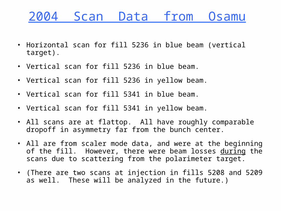
2004 Scan Data from Osamu
• Horizontal scan for fill 5236 in blue beam (vertical target).
• Vertical scan for fill 5236 in blue beam.
• Vertical scan for fill 5236 in yellow beam.
• Vertical scan for fill 5341 in blue beam.
• Vertical scan for fill 5341 in yellow beam.
• All scans are at flattop. All have roughly comparable dropoff in asymmetry far from the bunch center.
• All are from scaler mode data, and were at the beginning of the fill. However, there were beam losses during the scans due to scattering from the polarimeter target.
• (There are two scans at injection in fills 5208 and 5209 as well. These will be analyzed in the future.)
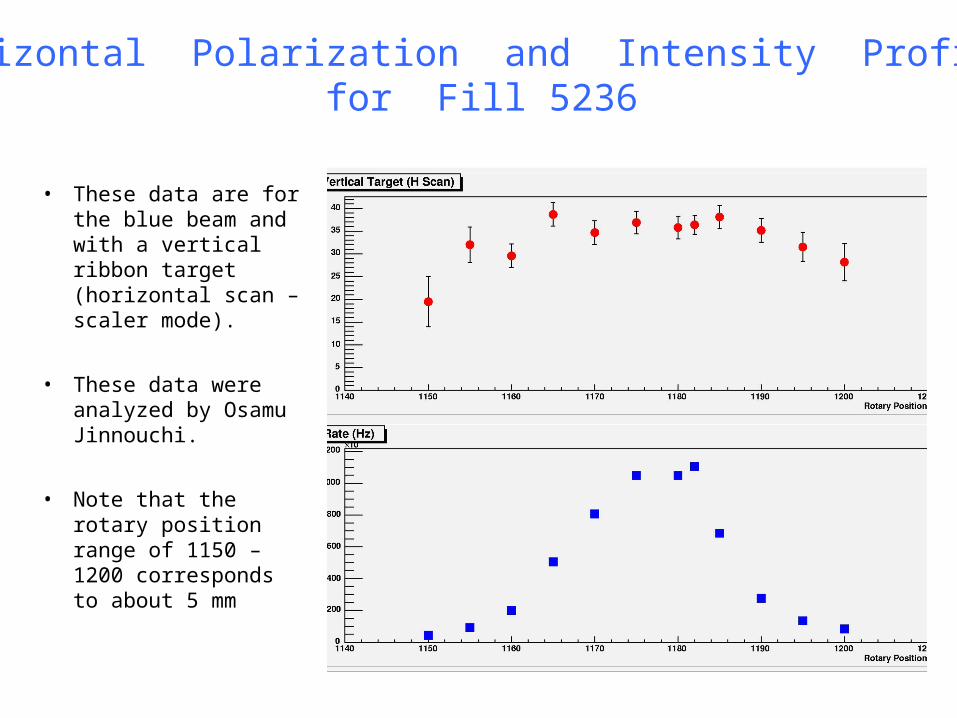
• These data are for the blue beam and with a vertical ribbon target (horizontal scan – scaler mode).
• These data were analyzed by Osamu Jinnouchi.
• Note that the rotary position range of 1150 – 1200 corresponds to about 5 mm
Horizontal Polarization and Intensity Profilesfor Fill 5236
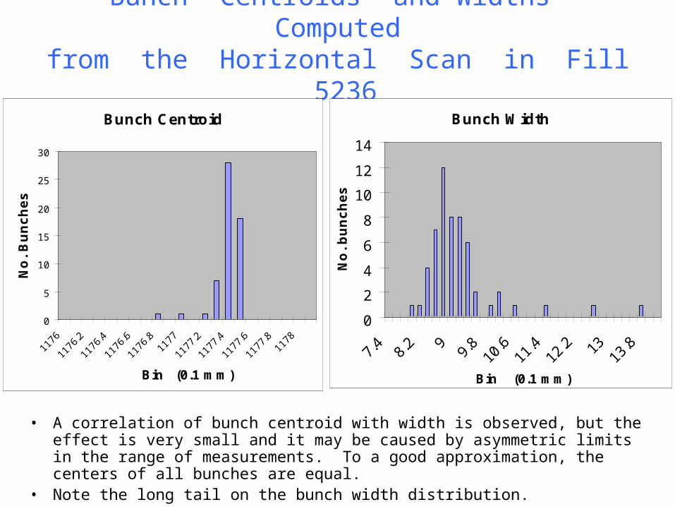
Bunch Centroids and Widths Computedfrom the Horizontal Scan in Fill 5236
• A correlation of bunch centroid with width is observed, but the effect is very small and it may be caused by asymmetric limits in the range of measurements. To a good approximation, the centers of all bunches are equal.
• Note the long tail on the bunch width distribution.
Bunch Centroid
0
5
10
15
20
25
30
1176
1176.2
1176.4
1176.6
1176.81177
1177.2
1177.4
1177.6
1177.81178
Bin (0.1 mm)
No
. B
un
ch
es
Bunch Width
0
2
4
6
8
10
12
14
7.4
8.2 9
9.8
10.6
11.4
12.2 13
13.8
Bin (0.1 mm)
No
. b
un
ch
es
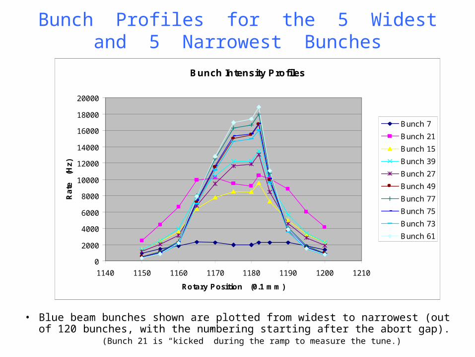
Bunch Profiles for the 5 Widestand 5 Narrowest Bunches
• Blue beam bunches shown are plotted from widest to narrowest (out of 120 bunches, with the numbering starting after the abort gap). (Bunch 21 is “kicked” during the ramp to measure the tune.)
Bunch Intensity Profiles
0
2000
4000
6000
8000
10000
12000
14000
16000
18000
20000
1140 1150 1160 1170 1180 1190 1200 1210
Rotary Position (0.1 mm)
Ra
te
(H
z)
Bunch 7
Bunch 21
Bunch 15
Bunch 39
Bunch 27
Bunch 49
Bunch 77
Bunch 75
Bunch 73
Bunch 61
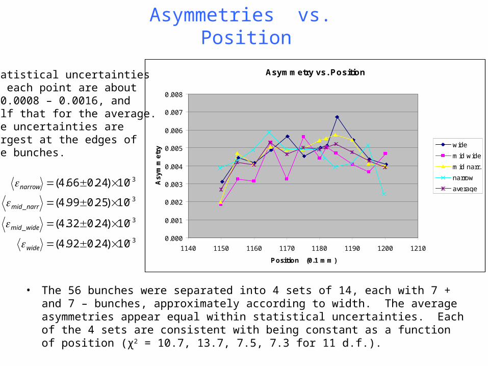
Asymmetries vs. Position
• The 56 bunches were separated into 4 sets of 14, each with 7 + and 7 – bunches, approximately according to width. The average asymmetries appear equal within statistical uncertainties. Each of the 4 sets are consistent with being constant as a function of position (χ2 = 10.7, 13.7, 7.5, 7.3 for 11 d.f.).
3
3_
3_
3
10)24.092.4(
10)24.032.4(
10)25.099.4(
10)24.066.4(
wide
widemid
narrmid
narrow
Asymmetry vs. Position
0.000
0.001
0.002
0.003
0.004
0.005
0.006
0.007
0.008
1140 1150 1160 1170 1180 1190 1200 1210
Position (0.1 mm)
As
ym
me
try wide
mid wide
mid narr.
narrow
average
Statistical uncertaintieson each point are about± 0.0008 – 0.0016, andhalf that for the average.The uncertainties arelargest at the edges ofthe bunches.
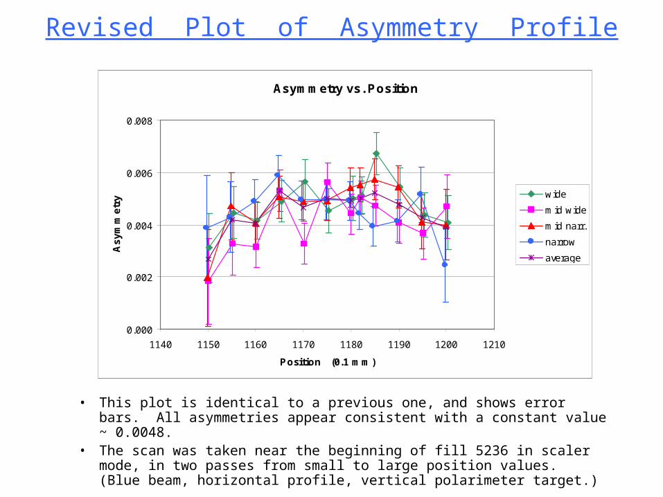
Revised Plot of Asymmetry Profile
• This plot is identical to a previous one, and shows error bars. All asymmetries appear consistent with a constant value ~ 0.0048.
• The scan was taken near the beginning of fill 5236 in scaler mode, in two passes from small to large position values. (Blue beam, horizontal profile, vertical polarimeter target.)
Asymmetry vs. Position
0.000
0.002
0.004
0.006
0.008
1140 1150 1160 1170 1180 1190 1200 1210
Position (0.1 mm)
As
ym
me
try wide
mid wide
mid narr.
narrow
average
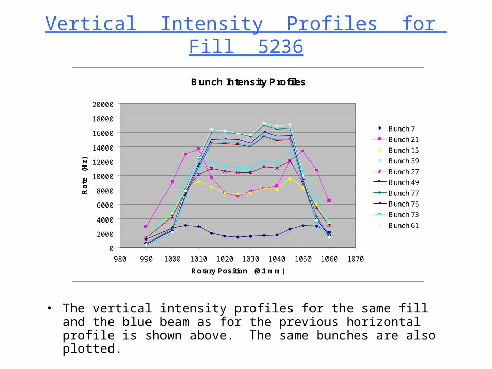
Vertical Intensity Profiles for Fill 5236
• The vertical intensity profiles for the same fill and the blue beam as for the previous horizontal profile is shown above. The same bunches are also plotted.
Bunch Intensity Profiles
0
2000
4000
6000
8000
10000
12000
14000
16000
18000
20000
980 990 1000 1010 1020 1030 1040 1050 1060 1070
Rotary Position (0.1 mm)
Ra
te
(Hz)
Bunch 7
Bunch 21
Bunch 15
Bunch 39
Bunch 27
Bunch 49
Bunch 77
Bunch 75
Bunch 73
Bunch 61
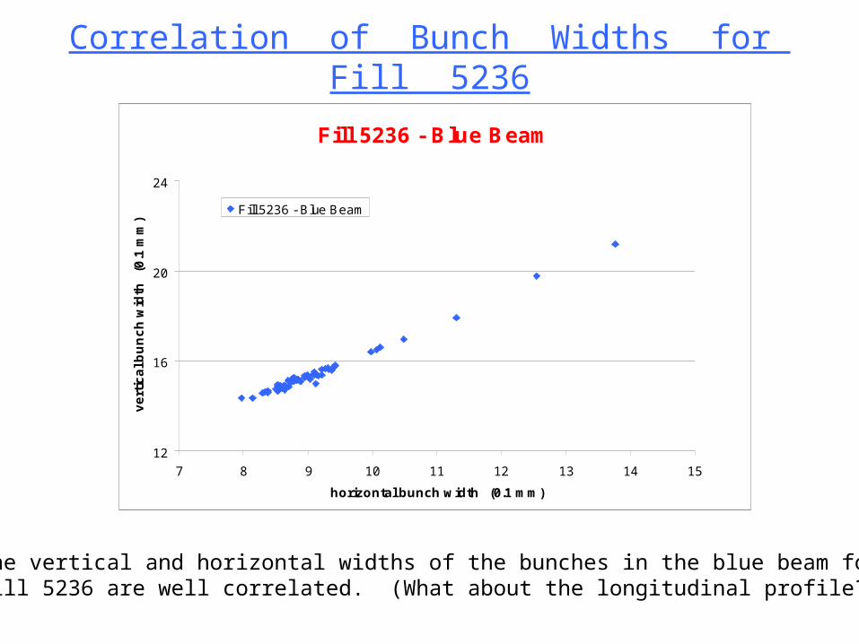
Correlation of Bunch Widths for Fill 5236
Fill 5236 - Blue Beam
12
16
20
24
7 8 9 10 11 12 13 14 15
horizontal bunch width (0.1 mm)
ve
rtic
al b
un
ch
wid
th
(0.1
mm
)
Fill 5236 - Blue Beam
The vertical and horizontal widths of the bunches in the blue beam for fill 5236 are well correlated. (What about the longitudinal profile??)
• Inserted comment by du:
• Is correlation because rms depends on amplitude with the size at the base constant?
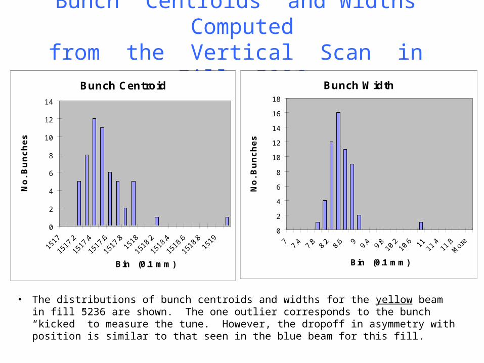
Bunch Centroids and Widths Computedfrom the Vertical Scan in Fill 5236
• The distributions of bunch centroids and widths for the yellow beam in fill 5236 are shown. The one outlier corresponds to the bunch “kicked” to measure the tune. However, the dropoff in asymmetry with position is similar to that seen in the blue beam for this fill.
Bunch Width
0
2
4
6
8
10
12
14
16
18
77.4 7.8 8.2 8.6 9
9.4 9.810.2
10.6 1111.4
11.8M
ore
Bin (0.1 mm)N
o.
Bu
nc
he
s
Bunch Centroid
0
2
4
6
8
10
12
14
1517
1517.2
1517.4
1517.6
1517.81518
1518.2
1518.4
1518.6
1518.81519
Bin (0.1 mm)
No
. B
un
ch
es
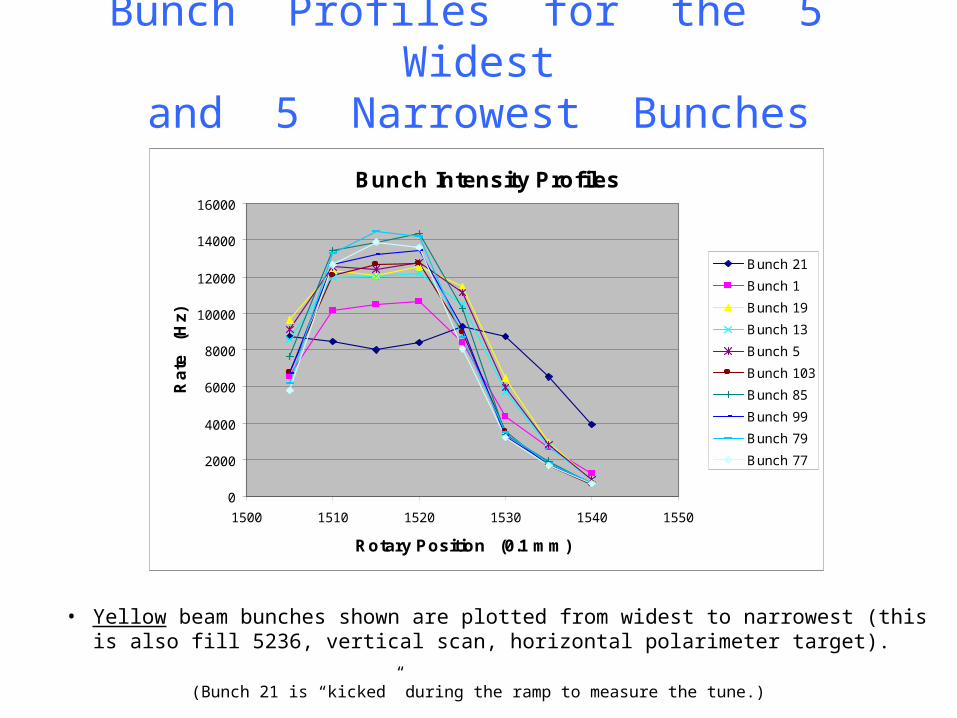
Bunch Profiles for the 5 Widestand 5 Narrowest Bunches
• Yellow beam bunches shown are plotted from widest to narrowest (this is also fill 5236, vertical scan, horizontal polarimeter target). (Bunch 21 is “kicked” during the ramp to measure the tune.)
Bunch Intensity Profiles
0
2000
4000
6000
8000
10000
12000
14000
16000
1500 1510 1520 1530 1540 1550
Rotary Position (0.1 mm)
Ra
te
(Hz)
Bunch 21
Bunch 1
Bunch 19
Bunch 13
Bunch 5
Bunch 103
Bunch 85
Bunch 99
Bunch 79
Bunch 77
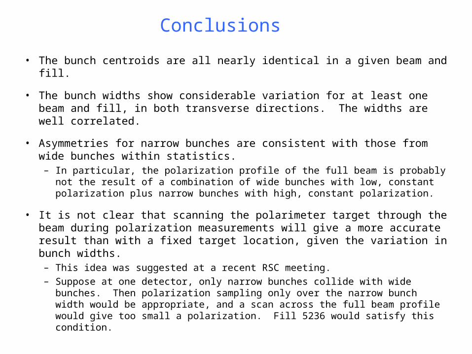
Conclusions
• The bunch centroids are all nearly identical in a given beam and fill.
• The bunch widths show considerable variation for at least one beam and fill, in both transverse directions. The widths are well correlated.
• Asymmetries for narrow bunches are consistent with those from wide bunches within statistics.– In particular, the polarization profile of the full beam is probably not the
result of a combination of wide bunches with low, constant polarization plus narrow bunches with high, constant polarization.
• It is not clear that scanning the polarimeter target through the beam during polarization measurements will give a more accurate result than with a fixed target location, given the variation in bunch widths.– This idea was suggested at a recent RSC meeting.
– Suppose at one detector, only narrow bunches collide with wide bunches. Then polarization sampling only over the narrow bunch width would be appropriate, and a scan across the full beam profile would give too small a polarization. Fill 5236 would satisfy this condition.
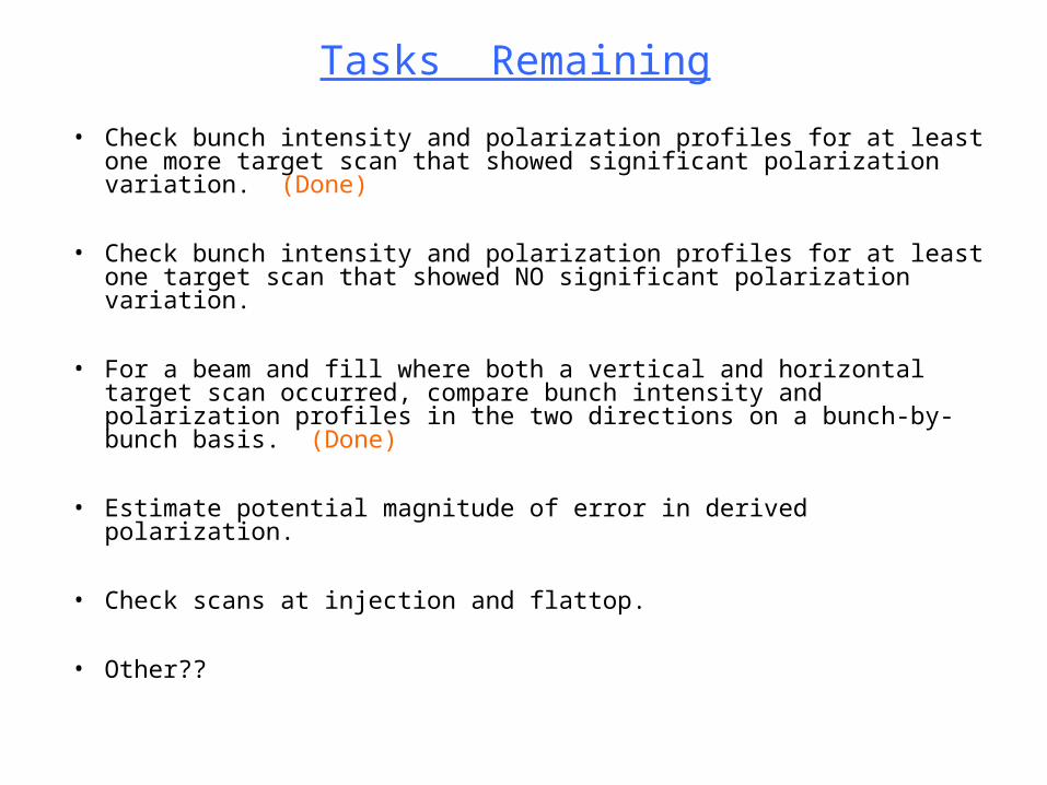
Tasks Remaining
• Check bunch intensity and polarization profiles for at least one more target scan that showed significant polarization variation. (Done)
• Check bunch intensity and polarization profiles for at least one target scan that showed NO significant polarization variation.
• For a beam and fill where both a vertical and horizontal target scan occurred, compare bunch intensity and polarization profiles in the two directions on a bunch-by-bunch basis. (Done)
• Estimate potential magnitude of error in derived polarization.
• Check scans at injection and flattop.
• Other??
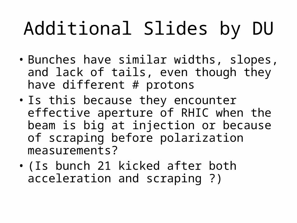
Additional Slides by DU
• Bunches have similar widths, slopes, and lack of tails, even though they have different # protons
• Is this because they encounter effective aperture of RHIC when the beam is big at injection or because of scraping before polarization measurements?
• (Is bunch 21 kicked after both acceleration and scraping ?)
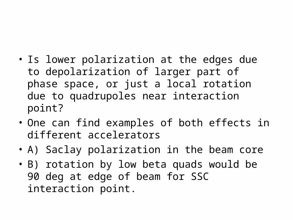
• Is lower polarization at the edges due to depolarization of larger part of phase space, or just a local rotation due to quadrupoles near interaction point?
• One can find examples of both effects in different accelerators
• A) Saclay polarization in the beam core• B) rotation by low beta quads would be 90 deg
at edge of beam for SSC interaction point.
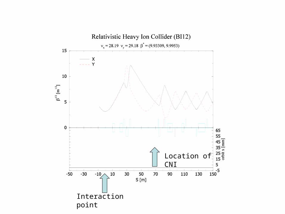
Location of CNI
Interaction point