polarimetry in hall a - thomas jefferson national … polarimeter in hall a compton polarimeter...
TRANSCRIPT
Outline
Polarimetry in Hall A
E.Chudakov1
1Hall A, JLab
Moller-12 Workshop, Aug 2008
E.Chudakov Moller-12 Workshop, Aug 2008 Polarimetry in Hall A 1
Outline
Outline
1 IntroductionCompton and Møller Polarimetry
2 Polarimeter in Hall ACompton PolarimeterMøller PolarimeterHigh field upgradeAtomic hydrogen trap
3 SummarySummary
E.Chudakov Moller-12 Workshop, Aug 2008 Polarimetry in Hall A 2
Outline
Outline
1 IntroductionCompton and Møller Polarimetry
2 Polarimeter in Hall ACompton PolarimeterMøller PolarimeterHigh field upgradeAtomic hydrogen trap
3 SummarySummary
E.Chudakov Moller-12 Workshop, Aug 2008 Polarimetry in Hall A 2
Outline
Outline
1 IntroductionCompton and Møller Polarimetry
2 Polarimeter in Hall ACompton PolarimeterMøller PolarimeterHigh field upgradeAtomic hydrogen trap
3 SummarySummary
E.Chudakov Moller-12 Workshop, Aug 2008 Polarimetry in Hall A 2
Introduction Polarimeters in Hall A Summary
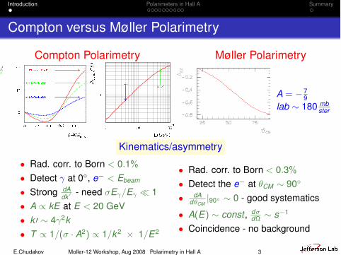
Compton versus Møller Polarimetry
Compton Polarimetry Møller Polarimetry
A = ! 79
lab " 180 mbster
Kinematics/asymmetry
• Rad. corr. to Born < 0.1%
• Detect ! at 0!, e" < Ebeam
• Strong dAdk ! - need "E!/E! # 1
• A $ kE at E < 20 GeV• k % " 4!2k• T $ 1/(" · A2) $ 1/k2 & 1/E2
• Rad. corr. to Born < 0.3%
• Detect the e" at #CM " 90!
• dAd"CM
|90" " 0 - good systematics
• A(E) " const , d#d! " s"1
• Coincidence - no background
E.Chudakov Moller-12 Workshop, Aug 2008 Polarimetry in Hall A 3
Introduction Polarimeters in Hall A Summary
Compton versus Møller Polarimetry
Compton Polarimetry Møller Polarimetry
A = ! 79
lab " 180 mbster
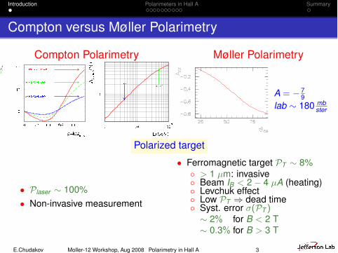
Polarized target
• Plaser " 100%• Non-invasive measurement
• Ferromagnetic target PT " 8%' > 1 µm: invasive' Beam IB < 2! 4 µA (heating)' Levchuk effect' Low PT ( dead time' Syst. error "(PT )" 2% for B < 2 T" 0.3% for B > 3 T
E.Chudakov Moller-12 Workshop, Aug 2008 Polarimetry in Hall A 3
Introduction Polarimeters in Hall A Summary
Compton versus Møller Polarimetry
Compton Polarimetry Møller Polarimetry
A = ! 79
lab " 180 mbster
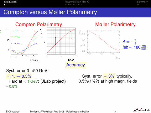
AccuracySyst. error 3)50 GeV:" 1. ) 0.5%Hard at < 1 GeV: (JLab project)"0.8%
Syst. error " 3% typically,0.5%(1%?) at high magn. fields
E.Chudakov Moller-12 Workshop, Aug 2008 Polarimetry in Hall A 3
Introduction Polarimeters in Hall A Summary
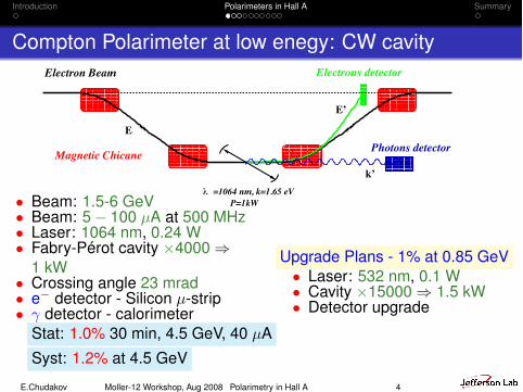
Compton Polarimeter at low enegy: CW cavity
λP=1kW
=1064 nm, k=1.65 eV
Electron Beam Electrons detector
Photons detectorMagnetic Chicanek’
E’
E
• Beam: 1.5-6 GeV• Beam: 5! 100 µA at 500 MHz• Laser: 1064 nm, 0.24 W• Fabry-Pérot cavity &4000 (
1 kW• Crossing angle 23 mrad• e! detector - Silicon µ-strip• ! detector - calorimeter
Stat: 1.0% 30 min, 4.5 GeV, 40 µASyst: 1.2% at 4.5 GeV
Upgrade Plans - 1% at 0.85 GeV• Laser: 532 nm, 0.1 W• Cavity &15000 ( 1.5 kW• Detector upgrade
E.Chudakov Moller-12 Workshop, Aug 2008 Polarimetry in Hall A 4
Introduction Polarimeters in Hall A Summary
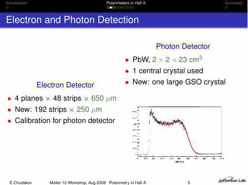
Electron and Photon Detection
Electron Detector
• 4 planes & 48 strips & 650 µm• New: 192 strips & 250 µm• Calibration for photon detector
Photon Detector
• PbW, 2& 2& 23 cm3
• 1 central crystal used• New: one large GSO crystal
function
R!ADC; k" # A e!ADC$ADC0"2=2s2R ; ADCXADC0
R!ADC; k" #
A !1$ d" e!ADC$ADC0"2=2s2L % Z% !d$ Z"ADC4
ADC40
" #
,
ADCpADC0 !9"
where A, ADC0 and sR=L are Gaussian para-meters, and Z, d denote proportional amplitudesP4!0"=A and P4!x0"=A, as described in Fig. 4. A isfixed by normalizing the integral of the responsefunction to 1 in the denominator of Eq. (7). Theremaining five parameters are functions of thescattered photon energy k, fitted to data from allelectron detector strips which fired. The Gaussianwidths sR=L are corrected for smearing due to thewidth of the electron strips (sE & 5MeV).
The electron detector cannot be put closer thana few mm to the beam axis and thus restricts therange over which the response function can bedetermined. For instance, only photon energiesbetween 150 and 340MeV (Compton edge) couldbe explored with a 4.6GeV beam. The determina-
tion of the calorimeter response function is wellcontrolled inside this energy range but the extra-polation to lower energy induces larger systematicerrors (see Section 6).
5.2. Calibration and analyzing power
The response function measured during aspecific reference run has to be corrected for meangain variations when used to analyze a later run.To this end a calibration coefficient l is introducedwhich accounts for gain corrections
R!ADC; k" # R!ADC
l; k" (10)
l is fitted to the experimental spectrum of each run(Fig. 5) using the convolution of the unpolarizedCompton cross-section ds0!k"=dk with the re-sponse function
dN!ADC"dADC
#Z kmax
0
ds0!k"dk
R!ADC; k"dk. (11)
The probability of photon detection is deducedfrom Eq. (7), where the lower integration bound-ary ADCs is replaced by ADCs=l. The analyzing
ARTICLE IN PRESS
Fig. 5. Fit of the experimental photon spectrum using the smeared cross-section. The fit range is restricted to the validity energy rangeof the modelling.
S. Escoffier et al. / Nuclear Instruments and Methods in Physics Research A 551 (2005) 563–574568
E.Chudakov Moller-12 Workshop, Aug 2008 Polarimetry in Hall A 5
Introduction Polarimeters in Hall A Summary
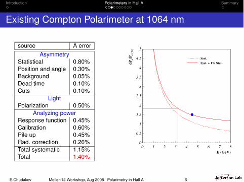
Existing Compton Polarimeter at 1064 nm
source A errorAsymmetry
Statistical 0.80%Position and angle 0.30%Background 0.05%Dead time 0.10%Cuts 0.10%
LightPolarization 0.50%
Analyzing powerResponse function 0.45%Calibration 0.60%Pile up 0.45%Rad. correction 0.26%Total systematic 1.15%Total 1.40%
E (GeV)
δPe/P
e (%
)
Syst.Syst. + 1% Stat.
0
0.5
1
1.5
2
2.5
3
3.5
4
4.5
5
0 1 2 3 4 5 6 7 8
E.Chudakov Moller-12 Workshop, Aug 2008 Polarimetry in Hall A 6
Introduction Polarimeters in Hall A Summary
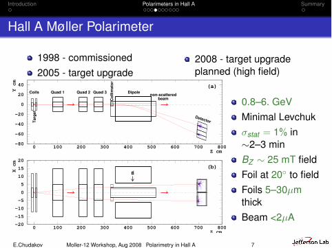
Hall A Møller Polarimeter
1998 - commissioned2005 - target upgrade
2008 - target upgradeplanned (high field)
-80
-60
-40
-20
0
20
40
0 100 200 300 400 500 600 700 800Z cm
Y cm (a)
Targ
et
Col
limat
or
Coils Quad 1 Quad 2 Quad 3 Dipole
Detector
non-scatteredbeam
-20-15-10-505101520
0 100 200 300 400 500 600 700 800Z cm
X cm (b)
B!
0.8–6. GeVMinimal Levchuk"stat = 1% in"2–3 minBZ " 25 mT fieldFoil at 20" to fieldFoils 5–30µmthickBeam <2µA
E.Chudakov Moller-12 Workshop, Aug 2008 Polarimetry in Hall A 7
Introduction Polarimeters in Hall A Summary
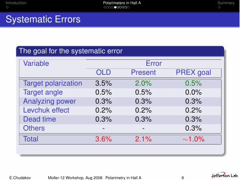
Systematic Errors
The goal for the systematic error
Variable ErrorOLD Present PREX goal
Target polarization 3.5% 2.0% 0.5%Target angle 0.5% 0.5% 0.0%Analyzing power 0.3% 0.3% 0.3%Levchuk effect 0.2% 0.2% 0.2%Dead time 0.3% 0.3% 0.3%Others - - 0.3%Total 3.6% 2.1% "1.0%
E.Chudakov Moller-12 Workshop, Aug 2008 Polarimetry in Hall A 8
Introduction Polarimeters in Hall A Summary
How to measure the “real” beam?
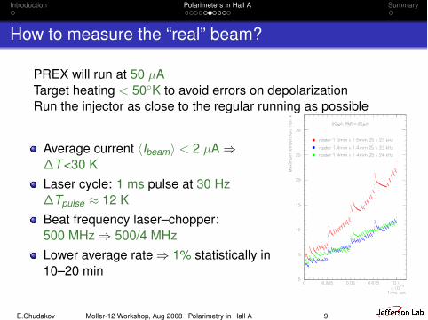
PREX will run at 50 µATarget heating < 50"K to avoid errors on depolarizationRun the injector as close to the regular running as possible
Average current *Ibeam+ < 2 µA (!T<30 KLaser cycle: 1 ms pulse at 30 Hz!Tpulse , 12 KBeat frequency laser–chopper:500 MHz ( 500/4 MHzLower average rate ( 1% statistically in10–20 min
E.Chudakov Moller-12 Workshop, Aug 2008 Polarimetry in Hall A 9
Introduction Polarimeters in Hall A Summary
Appendix:Bunch suppression
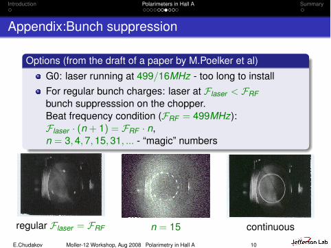
Options (from the draft of a paper by M.Poelker et al)G0: laser running at 499/16MHz - too long to installFor regular bunch charges: laser at Flaser < FRFbunch suppresssion on the chopper.Beat frequency condition (FRF = 499MHz):Flaser · (n + 1) = FRF · n,n = 3, 4, 7, 15, 31, ... - “magic” numbers
regular Flaser = FRF n = 15 continuous
E.Chudakov Moller-12 Workshop, Aug 2008 Polarimetry in Hall A 10
Introduction Polarimeters in Hall A Summary
Appendix:Beat frequency mode - leak through
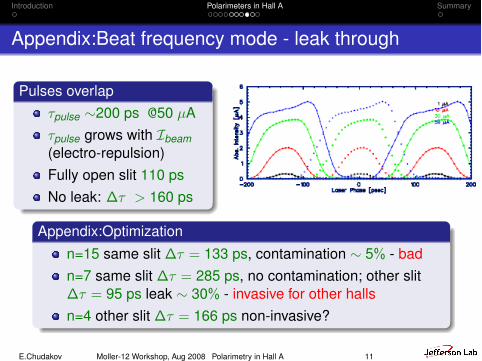
Pulses overlap$pulse "200 ps @50 µA$pulse grows with Ibeam(electro-repulsion)Fully open slit 110 psNo leak: !$ > 160 ps
Appendix:Optimizationn=15 same slit !$ = 133 ps, contamination " 5% - badn=7 same slit !$ = 285 ps, no contamination; other slit!$ = 95 ps leak " 30% - invasive for other hallsn=4 other slit !$ = 166 ps non-invasive?
E.Chudakov Moller-12 Workshop, Aug 2008 Polarimetry in Hall A 11
Introduction Polarimeters in Hall A Summary
Macro-pulsing - tune beam
Pulses !t > 4 µs at repetition rate k & 30 HzLimitation: at Iinst = 50 µA accelerator stabilization time" 100 µsNo micro-suppresssion: !t = 1 ms at 30 HzMicro-suppresssion n=4: !t = 1 ms at 120 Hz
E.Chudakov Moller-12 Workshop, Aug 2008 Polarimetry in Hall A 12
Introduction Polarimeters in Hall A Summary
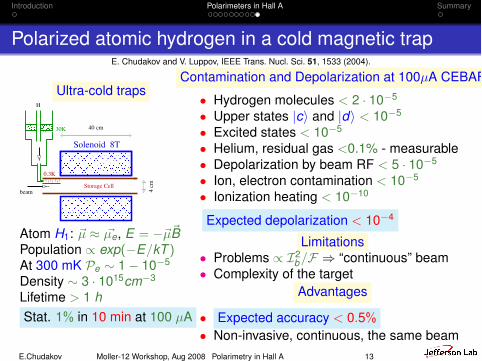
Polarized atomic hydrogen in a cold magnetic trapE. Chudakov and V. Luppov, IEEE Trans. Nucl. Sci. 51, 1533 (2004).
Ultra-cold traps
30K
0.3K
H
Solenoid 8T
beamStorage Cell
4 cm
40 cm
Atom H1: %µ , %µe, E = !%µ%BPopulation $ exp(!E/kT )At 300 mK Pe " 1! 10"5
Density " 3 · 1015cm"3
Lifetime > 1 hStat. 1% in 10 min at 100 µA
Contamination and Depolarization at 100µA CEBAF
• Hydrogen molecules < 2 · 10"5
• Upper states |c+ and |d+ < 10"5
• Excited states < 10"5
• Helium, residual gas <0.1% - measurable• Depolarization by beam RF < 5 · 10"5
• Ion, electron contamination < 10"5
• Ionization heating < 10"10
Expected depolarization < 10"4
Limitations• Problems $ I2
b/F ( “continuous” beam• Complexity of the target
Advantages
• Expected accuracy < 0.5%• Non-invasive, continuous, the same beam
E.Chudakov Moller-12 Workshop, Aug 2008 Polarimetry in Hall A 13
Introduction Polarimeters in Hall A Summary
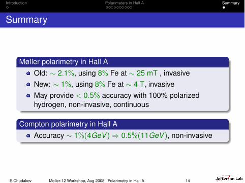
Summary
Møller polarimetry in Hall AOld: " 2.1%, using 8% Fe at " 25 mT , invasiveNew: " 1%, using 8% Fe at " 4 T, invasiveMay provide < 0.5% accuracy with 100% polarizedhydrogen, non-invasive, continuous
Compton polarimetry in Hall AAccuracy " 1%(4GeV ) ( 0.5%(11GeV ), non-invasive
E.Chudakov Moller-12 Workshop, Aug 2008 Polarimetry in Hall A 14