polarimeter ads220 - cole-parmer adp220 polarimeter is a self-contained, general purpose, fully...
TRANSCRIPT

ADP220POLARIMETER
ADS220SACCHARIMETEROPERATORS MANUAL
Bellingham + Stanley Limited


OPERATORS MANUAL: ISSUE 3.1 FEBRUARY 2004
MANUAL CODE: 36-102
This manual is applicable to ADP220 polarimeters and ADS220 saccharimeters fitted with the following software:-
ADP22036-601Version 13, 14, 15, 16,17
ADS22036-611Version 3, 4, 5, 6, 7, 8
To display the code number of the software actually fitted, see page 3-1.
Trademark Acknowledgements
Epson, ESC/P are trademarks of Seiko Epson CorporationIBM and IBM PC are trademarks of International Business Machines CorporationDatac is a trademark of Datac plc’Centronics’ is a trademark of Centronics Data Computer Corporation’Genklene’ and ’Arklone’ are trademarks of ICI Chemicals & Polymers Limited’Windows’ is a trademark of Microsoft Corporation
© Copyright BELLINGHAM & STANLEY Ltd. 2002
All efforts have been made to ensure the accuracy of thecontents of this manual. However, Bellingham & Stanley Ltd.can assume no responsibility for any errors contained in themanual or their consequences.
Printed in United Kingdom
Bellingham & Stanley Ltd.Longfield Road, North Farm Industrial Estate,TUNBRIDGE WELLS, United Kingdom. TN2 3EYTelephone: 0 1892 500400Fax: 0 1892 543115
Bellingham & Stanley Inc.1000 Hurricane Shoals Road, Bldg D. Suite 300LAWRENCEVILLE, USA GA30043Telephone: 770 822 6898Fax: 770 822 9165


DECLARATION OF CONFORMITYaccording to ISO/IEC Guide 22 and EN 45014
Manufacturer’s Name Bellingham & Stanley Limited
Manufacturer’s Address Longfield Road,North Farm Industrial Estate,Tunbridge Wells,Kent TN2 3EYUnited Kingdom
declares that the product
Product Name ADP220 Automatic polarimeterADS220 Automatic saccharimeter
Model Number 36-20, 36-21
Product Options All
conforms to the following Product Specifications:
Safety IEC950:1991
EMC EN50081-1 - Emissions• EN55022 : Radiated Emissions to Class A• EN55022 : Conducted Emissions to Class A
EN50082-1 - Generic Immunity• IEC 801-2 : 1984 Electrostatic Discharge - Class 3, 8 KV• IEC 801-3 : 1984 Radio Frequency Susceptibility - Class 2, 3V/m• IEC 801-4 : 1988 Fast Burst Transients - Class 2, 1KV
Supplementary The product herewith complies with the requirements of the LowInformation Voltage Directive 73/23/EEC and the EMC Directive 89/336/EEC.

O P E R A T O R S M A N U A L
Contents
Installation 1
Basic Operation 2A Tour of the Instrument 2-1Measuring a Sample 2-3Setting the Measurement Mode 2-5Sampling Techniques 2-9Temperature Control and Compensation 2-10
Setting Up the System 3Passwords 3-1Calibration 3-2Configuration 3-3User Defined Temperature Compensation 3-9User Defined Scales (ADP220 only) 3-10Purity Settings & Operation (ADS220 only) 3-12ADP Key Function Map 3-ADPADS Key Function Map 3-ADS
Error Conditions & Messages 4
Specification 5
Spares & Accessories 6Spare Parts 6-1
CONTENTS


S E C T I O N 1
Installation
Unpacking 1-1Contents List 1-1Part Numbers 1-1Positioning the System 1-1Mains Connection 1-2Power Supply Adaptor 1-2
INSTALLATION 1


UNPACKING Carefully remove all of the packing material. It is recommended thatthe box and other packing materials are retained so that, should theneed arise, the instrument can be safely returned to the manufacturer.
Check that all parts listed below are present and that no transitdamage has occurred. If any are damaged or missing then contact thesupplier immediately.
CONTENTS LIST 1 Remote Temperature Sensor, 36-1431 Power Supply Unit, 55-1041 Mains Lead, see below for part no.1 Operators Manual, 36-1021 200mm centre filling sample tube, 35-47
ADP220 only1 ADP220 Polarimeter, 36-220
ADS220 only1 ADS220 Saccharimeter, 36-222
PART NUMBERSDescription Part number
ADP220 comprisingMain instrument
36-2036-220
ADS220 comprisingMain instrument
36-2136-222
UKVersion
230V
EuroVersion
230V
USVersion
110V
Mains lead (for 55-104) 61-191 61-193 61-192
POSITIONING THESYSTEM
Place the instrument on a flat and stable bench that is:-* dry and indoors* away from draughty or hot equipment like fans or heaters* out of direct sunlight or strong ambient light* away from potential sources of interference such as RFI
generating equipment* within easy reach of a power point* not using a power circuit that also has large motors or noise-
generating equipment connected to it.
INSTALLATION 1-1

MAINSCONNECTION
The power supply adaptor is supplied with a moulded mains leadwhich has a plug to suit one of several socket types:-
UK 13 Amp square pin to BS1363/AEU European Schuko plugUS 3 pin American plug
Mains cord wire colours
LINE(PHASE)
NEUTRAL(RETURN)
EARTH(GROUND)
UK (230V) brown blue green/yellow
EU (230V) brown blue green/yellow
US (110V) black white green
This power supply must be earthed. Earth terminal is used forfunctional earth only.
POWER SUPPLYADAPTER
WARNING:* For indoor use only.* Must be kept dry.* No user serviceable parts inside.* Do not open.* Do not cover, designed to operate with free air convection.* No cleaning required.
1-2 INSTALLATION

S E C T I O N 2
Basic Operation
A Tour of the Instrument 2-1Operators Panel 2-1System Reset 2-1Temperature Measurement 2-2Power Supply 2-2Services Panel 2-2Entering a Number 2-2
Measuring a Sample 2-3Reading 2-3Zeroing 2-3Print 2-4
Setting the Measurement Mode 2-5Entering a Password 2-5Selecting a Scale 2-5Setting a Multiplication factor 2-6Setting the Temperature Compensation 2-6Angular degree range (ADP220 only) 2-7
Sampling Techniques 2-9Cleaning 2-9Sample Application 2-9Specific Rotation 2-9
Temperature Control and Compensation 2-10Why Monitor the Temperature? 2-10
BASIC OPERATION 2


A Tour of the Instrument
The ADP220 polarimeter is a self-contained, general purpose, fully automatic polarimeter suitablefor measuring the rotation of optically active samples. It is housed in a rigid polyurethane foammoulded case which is light in weight whilst being extremely rugged and has a high resistance tochemical attack from the majority of commonly used samples. It incorporates a range ofmeasurement scales and other facilities which are accessed via a simple and user-friendly operatorspanel.
The ADS220 saccharimeter is similar in construction to the ADP220 but is specifically tailored tosuit the measurement of sugar solutions including the calculation of sugar purity with the use of arefractometer.
OPERATORSPANEL
The reading display is purely numeric and is formed from large, highcontrast digits. The functions of the four "soft keys" are shown on theupper line of the alpha-numeric display and provide access to all of theinstrument control and data options. The lower line of the alpha-numeric display and the numeric keys provide a means of enteringand displaying prompts and data.
SYSTEM RESET Pressing the two outermost soft-keys together is referred to asSYSTEM RESET and will reset theinstrument back to a startingcondition, as if it had just been
switched on. If at any time the instrument fails to respond to the soft-keys or produces nonsensical data it may be restarted by pressingSYSTEM RESET or by turning the power off then on.
Use of SYSTEM RESET is also a valid method of terminating lengthyoperations, should the operator so desire.
BASIC OPERATION 2-1

TEMPERATUREMEASUREMENT
All models are fitted with the "chamber" temperature sensor probe inthe reading chamber and have a separate "sample" temperature sensorprobe which can be placed in a "centre filling" sample tube. Either thechamber, or the sample, sensor probe can be pre-selected to be usedfor display and temperature compensation. See page 3-6.
POWER SUPPLY Power for the instruments is supplied from an external adaptor whichis not sealed against the ingress of moisture and should be kept dryand away from damp areas at all times.
SERVICESPANEL
The service panel can be found mounted on the rear face of theinstrument, which contains the following:
- ON/OFF switch- Power supply connector- RS232C serial port (to output data to a printer or computer)- Refractometer port (used on the ADS to input brix data from an
RFM refractometer)- Parallel printer port- Sample temperature probe connector
ENTERING ANUMBER
This instrument will accept numeric input in either fixed decimal pointformat, e.g. 123.4 or in scientific notation as 1.234E2. One of the soft-keys (second from left) gives access to the minus (-), decimal point (.)and exponent (E) symbols that will be required to enter both numericalformats. As the operator enters the number the instrument respondsto the key strokes by changing the symbol that the soft-key offers. Ifan error is made while entering the number the operator may use theCLEAR soft-key to erase the entry. The ENTER soft-key is availablethroughout the process and may be pressed at any time to accept theentry. Note that if the number being entered is negative, then pressthe minus soft-key before entering the number. Otherwise, if thenumber is less than 1, then press 0 first to show the decimal pointsoft-key.
2-2 BASIC OPERATION

Measuring a Sample
Before switching on, ensure that there is not a sample tube or quartz control plate in themeasurement chamber. After switching on the instrument the Reading Display will be blank and theinformation display will show the reading and temperature modes. The instrument will only starttaking readings when the reading mechanism has reached operating speed; this will only takeapproximately half a minute. In order to take accurate readings, allow 30 minutes for theinstrument to stabilise, as specified in ICUMSA procedures.
READING Fill a sample tube with your sample. Lift open the chamber cover andplace the tube on the two rails.
The instrument will now starttaking readings continually.You should notice that thereading fluctuates as it settles.Note the wave symbol on thebottom line.
There are 3 reading statusmodes, all of which aredisplayed in the middle of thedisplay on the bottom line.
The cross symbolises that the reading displayed has nomeaning, mainly caused because the light path is being blockedor because the reading mechanism has not reached its
operating speed.
The wave symbol is displayed when the reading is stabilising.The length of time for the reading to stabilise will depend on thesetting of the reading response parameter.
The tick is displayed when the reading has stabilised. Thedisplayed results will now be correct.
Whilst the instrument is taking readings, it will also be updating boththe temperature and o.d. (optical density) results.
ZEROING Take a clean empty sample tube and placein the chamber. Wait for the instrument tostabilise, using the reading status symbol asa guide. When stable press ZERO. The
displayed reading will now change to 0.00.
BASIC OPERATION 2-3

PRINT If an optional printer is connected, thereading may now be recorded by pressingthe PRINT key. The reading value isaccompanied by scale identification codes
and additional data depending upon the instrument settings. Typicalprintouts are shown below.
2-4 BASIC OPERATION

Setting the Measurement Mode
ENTERING APASSWORD
The ADP220 polarimeter and ADS220saccharimeter have 2 user definedpasswords. The "operator" password allowsaccess to the MODE functions only and the"supervisor" which provides unrestrictedoperation of all MODE and SETUP functions.
After pressing MODE the user is prompted to enter the password. Thefirst three keystrokes will be accepted and, if found to match thepassword, will allow the user to continue.
If the password is incorrect the Key Function Display will return to theinitial options.
See "Setting Up The System", page 3-1, for details of how to change (orcancel) the passwords.
Note : The password entry screen is not shown in subsequent keypressdiagrams
SELECTINGA SCALE
First press MODE then repeatedly pressingSCALE will step through the availablemeasurement scales. The ADP220 has 2scales, °a and °z that are always in the listand in addition, any of five user definedscales can be included. The ADS220 hasthe 2 standard scales and a pu scale whichis used to initiate the sugar purity mode.
u1, u2, u3, u4 & u5 can be set by the operator to specific productunits. See page 3-10 for more details.
°a angular degree Note 1
°z international sugar scale (ISS)
ADP220u1 user defined scale 1u2 user defined scale 2u3 user defined scale 3u4 user defined scale 4u5 user defined scale 5
ADS220pu sugar purity calculation mode
Note 1: The default reading range for the °a scale is -85 to +85 . If the°a scale is selected on an ADP220 and QUIT is pressed from theMODE menu the instrument will request a reading range.Pressing SLCT will select the default range. If it is necessary tochange this range see "ANGULAR DEGREE RANGE" later inthis section.
BASIC OPERATION 2-5

SETTING AMULTIPLICATION
FACTOR
First press MODE then press MLTPY. Theuser will be requested to enter amultiplication factor. This factor will bemultiplied with the measurement reading, tocreate the displayed reading.
Example
If you are using a 100mm length sampletube but want to display the equivalent reading result for a 200mmlength tube, then enter a multiplication factor of 2.
Note : If the multiplication factor has been set to any value otherthan 1, an "x" will be displayed just after the scaleidentification code.See "Entering a Number", page 2-2, for details of how to enternumbers.
SETTING THETEMPERATURE
COMPENSATION
First press MODE, then repeatedly pressingTC will step through the 4 temperaturecompensation modes.
nc no compensationqc quartz temperature
compensationsc sugar temperature compensationuc user defined temperature
compensation Note 1
Note 1: See page 3-9 for detail on setting the user defined temperaturecompensation constant.
2-6 BASIC OPERATION

ANGULARDEGREERANGE
(ADP220 Only)
The Range setting is only available when theangular degree scale (°a) is selected. Thedefault range for the °a scale is -85° to +85°.Other possible ranges are:-
-355° to -185°-265° to -95°-175° to -5°
-85° to +85°+5° to +175°
+95° to +265°+185° to +355°
In order to select the range go to the MODEmenu by pressing MODE. If °a is alreadyselected press SCALE once followed byQUIT. The range setting will now bedisplayed. If the scale is not °a simply selectit and press QUIT.
All polarimeters measure the amount of rotation of a plane of polarisedlight and so it is only possible for the instrument to detect the positionof the rotated light beam over a 180° span. As shown in the diagramsbelow, the plane of light leaving a sample with a rotation of +110° isexactly the same as that from a sample with a rotation of -70°.Therefore, a sample with a rotation of +110° will display -70° on thedefault range.
0° Rotation +110° Rotation -70° Rotation
If the user is aware that the sample to be measured should have arotation greater than +85° then the correct value can be calculatedfrom
180 + Displayed Rotation
Alternatively, if the +5° to +175° (or the +95° to + 265°) scale isselected, then the correct rotation will be displayed.
If, in the above example, the user is unsure whether the correctrotation is -70° or +110°, then an additional measurement should betaken with a different length of tube (e.g. half the length of the firsttube). If the original true rotation was -70° then the second readingwill be -35°. Otherwise, if the original rotation was +110°, then thesecond reading will be +55°.
If any range other than -85° to +85° is selected, then a "+" will bedisplayed on the lower display immediately after the °a scale identifiercode, i.e. "°a+". If a Multiplication factor other than 1 has also beenselected (see page 2-6), then the scale code will be shown as "°a*".
BASIC OPERATION 2-7

With an empty sample tube and, therefore, no rotation, the readingwill be displayed as
"0.00", "180.00" or "---.--"
depending on which range has been selected. After the ZERO key hasbeen pressed, the display will temporarily show "0.00" and then revertto one of the displays shown above.
2-8 BASIC OPERATION

Sampling Techniques
In order to achieve the maximum performance from the ADP220 Series polarimeter and ADS220Series saccharimeter, it is essential that extreme care is taken when cleaning the sample tubes andapplying the sample to the tube.
Temperature stabilisation can cause drifting of the reading unless care is taken.
CLEANING Always clean the sample tube thoroughly, making sure that there areno traces of a previous sample which could dissolve into the latersample.
First empty the sample tube at one end by removing one of the endcaps. Next fill the sample tube from the open end so to dilute any ofthe sample. Rinse out the tube making sure to rinse the centre fillingshaft.Allow the water to drain and then leave to dry. If using an oil basedsample substitute methylated spirits for water. Rinsing withmethylated spirits is better than water as it evaporates faster.
NEVER use acetone, white spirit, ’Genklene’, ’Arklone’ or any abrasivecleansers on any painted surface or, particularly, the membranekeypad panel.
SAMPLEAPPLICATION
First take a clean assembled sample tube and zero the instrumentwith that tube. Then take out the tube and slowly pour in the sample.The tube should be filled up to a point where the sample reaches halfway up the centre filling shaft. Finally visually check that there are nobubbles at the end caps.
SPECIFICROTATION
The specific rotation for a sample can be determined by using theequation shown below.
where:is the specific rotation in angular degrees per dm and perg/cm3, at 20°C and measured using a sodium ’D’ light source
is the optical rotation in angular degrees at 20°C and measuredusing a sodium ’D’ light source
is the concentration of sucrose in g/cm3
is the length of the polarimeter tube in dm
The International Commission for Uniform Methods of Sugar Analysis(ICUMSA) have fixed values that should be used when working to theInternational Sugar Scale (ISS).
= 0.26010 g/cm3 = 26.0160g/100.00 cm3
= 2.00000 dm = 200.000mm
BASIC OPERATION 2-9

Temperature Control and Compensation
WHYMONITOR THE
TEMPERATURE?
As the optical rotation of liquids varies with temperature, it isimportant that the temperature of the sample is monitored orcontrolled.
The temperature coefficient of sugar solutions is small but can becorrected by selecting sc temperature compensation. Thecompensation calculations can either be based on the temperature ofthe chamber temperature sensor or on the remote sample sensorwhich can be fitted into a "centre filling" sample tube with the tip ofthe sensor actually touching the sample.
Similarly, the temperature coefficient of quartz control plates can becorrected for when by selecting qc temperature compensation.
Some other samples may have more significant temperaturecoefficients and so the temperature should be monitored andcorrections made to the displayed readings. The User DefinedTemperature Compensation mode enables the instrument toautomatically correct for samples other than sucrose and QuartzControl Plates with known temperature coefficients. (see page 3-9 forfurther details). Alternatively, a water jacketed sample tube can beused and connected to a water bath or circulator to accurately controlthe measurement temperature.
2-10 BASIC OPERATION

S E C T I O N 3
Setting Up the System
The QUIT soft-key can be used at any time during the following operations to return to the initialsoft-key options (Setup, Mode, Zero, Print), or to cancel the current operation.
Passwords 3-1Entering the Password 3-1Change Passwords 3-1Display the Software version 3-1
Calibration 3-2Set Span 3-2
Configuration 3-3Display Resolution 3-3Reading Response 3-3Alter RS232 (ADP220 only) 3-4Remote Operation (ADP220 only) 3-4Batch & Operator Codes 3-5Select Temperature Probe for Compensation 3-6Select Temperature Display Scale 3-6Setting the Clock 3-7Changing the Date Format 3-7Select a Printer Type 3-8Select Printer Port 3-8
User Defined Temperature Compensation 3-9Setting the User Defined Temperature Coefficient Constant 3-9Selecting the User Defined Temperature Compensation Mode 3-9
User Defined Scales (ADP220 only) 3-10Create a Special User Defined Scale 3-10Cancel a User Defined Scale 3-11
Purity Settings & Operation (ADS220 only) 3-12Purity Format 3-12Purity Constant 3-13Refractometer Type 3-13Connecting an RFM Refractometer 3-13Switching to Purity Mode 3-14Calculating Purity Values 3-14
ADP Key Function Map 3-ADPADS Key Function Map 3-ADS
SETTING UP THE SYSTEM 3


Passwords
All of the setting up functions described in this section are accessed by pressing the SETUP key,following which, the operator will be prompted to enter a password. There are 2 passwords in theADP220 and ADS220 Series instruments; the "operator" password and the "supervisor" password.The "operator" password allows access to the MODE functions only and the "supervisor" whichprovides unrestricted operation of all MODE and SETUP functions. Each password is a 3 digitnumber in the range 001 to 255 and is initially set as follows:-
"Operator" 123"Supervisor" 135
ENTERING THEPASSWORD
After pressing SETUP the user is promptedto enter the password. The first threekeystrokes will be accepted and, if found tomatch the password, will allow the user tocontinue.
If the password is incorrect the KeyFunction Display will return to the initial options.
Note : The password entry screen is not shown in subsequent keypressdiagrams
CHANGEPASSWORDS
The "operator" and "supervisor" passwordscan be changed to any three digit numbersin the range 001 to 255. The first threekeystrokes will be accepted; if an incorrectkey is pressed, QUIT and start again.
Setting the "operator" password to 000 will give unrestricted access tothe MODE functions and the "Key in password:" screen will not bedisplayed after pressing MODE.Setting the "supervisor" password to 000 will give unrestricted accessto both the MODE & SETUP functions and the "Key in password:"screen will not be displayed after pressing MODE or SETUP.
CAUTION!Access to the MODE & SETUP functions is only possible by enteringthe passwords.DO NOT FORGET THEM!
In the event of passwords being forgotten contact Bellingham &Stanley Service Department for assistance.
DISPLAY THESOFTWARE
VERSION
This keypress sequence will show thesoftware version on the lower line of thedisplay in the form:-
Prog: ADP220 36-601-13
Where36-601 is the software code
13 is the software version
SETTING UP THE SYSTEM 3-1

Calibration
The ADP220 and ADS220 instruments have two calibration adjustments. As described in section 2,ZERO corrects the calibration for day to day minor variations. This should be carried out simplywith an empty tube and, as such, can be performed at regular intervals; even before every newsample measurement.
The instruments also have a calibration span facility which can be used to check and, if necessary,correct the high end of the reading range using a Quartz Control Plate, an accurately preparedsugar solution or other sample of known value.
SET SPAN Place the sample into the sample chamberand close the lid.
Press ENTER to calibrate at the default valuedisplayed or key in the actual sample value.
Continuous readings will be taken until stableand then the calibration will be corrected tothe new value.
Notes:1. The span facility is only available with certain scales and
ranges.
The ADP220 will not span if degrees angular is selected with arange other than -85 to +85.
The ADS220 will not span if the purity calculation scale isselected.
The instrument will display"Invalid scale" or "Invalidrange" when CALIB ispressed and will disablethe SPAN facility.
Press QUIT to return back to the setup menu.
2. The span facility does not use the multiplication factor, so theactual value of the sample must be entered.
3. Should the span facility be used with an empty chamber theinstrument will show very erratic readings until the instrumentis either re-spanned or the span is reset. Should a sample of aknown value not be available the instrument can be returned tothe factory span value by defaulting the span setting (seesection 4-2).
3-2 SETTING UP THE SYSTEM

Configuration
DISPLAYRESOLUTION
First press SETUP, CONFIG & DSPLY, thenrepeatedly pressing RESOL alternatelyselects...
lo
and hi
The resolution of the measurement readingboth on the display and to the printer will beas shown in the table.
Reading Resolution
lo hi
0.1 0.01
READINGRESPONSE
First press SETUP, CONFIG & DSPLY, thenrepeatedly pressing RESPN alternatelyselects...
slow
and fast
The response setting will determine the lengthof time for the reading averaging, so fast willcome to a reading quicker but might fluctuate.A slow response will take longer to settle butshould give more stable results, particulary onhigh resolution scales such as °z.
SETTING UP THE SYSTEM 3-3

ALTER RS232(ADP220 Only)
There is an RS232C serial interface port onthe instrument rear panel. The RS232C baudrate and data word structure can be set byselecting ALTER RS232. There are three baudrates available, 300, 1200 & 9600, and twoword structures, either 7 bit with even parityor 8 bit with no parity. There is also a CR orCR-LF filter.
There is a combined XON/XOFF software andDSR/DTR type hardware handshake controlsystem with connections on the ’D’ type 9wayconnector as shown in the table below.
9way’D’ plugpin no.
Description Direction 54-0225way plug
pin no.
54-51
25way sktpin no.
9way sktpin no.
2 Receive data in 2 2 3
3 Transmitted data out 3 3 2
4 DTR out 6 6 6
5 Signal Ground 7 7 5
6 DSR in 20 20 4
The serial port can be used for sending data to a printer or forcommunication with a remote computer.
Interconnecting lead part no. 54-02 is suitable for connection to a printerand, when used in conjunction with interface adaptors part no. 54-51, forconnection to an IBM PC or equivalent.
REMOTEOPERATION
(ADP220 Only)
The serial port can be used for remote operation. Sending a <CR> (ascii13) will initiate a reading and return a string as shown below:
33.57 aq Ok 25.0’C 0.0
(reading) (scale) (reading status) (selected temperature) (od)
Other functions are available for specific applications. Please contactB+S for further details.
The "ADP220 Utility Program" code number 36-251 can also be used forremote operation and data logging.
3-4 SETTING UP THE SYSTEM

BATCH &OPERATOR
CODES
As well as being defined by the date and time,a printed reading can also be identified by twocode numbers; the Batch code which is a 6digit number and the Operator code which is 2digits.
Initially, both codes are inhibited fromoperation but either can be selected byentering BatOp numbers as follows:-
0 No Batch or Operator1 Batch code only2 Operator code only3 Batch & Operator codes
Other numbers could give unexpected results and so should not beentered.
When PRINT is pressed, you will be requested to enter a Batch code andthen an Operator code. If ENTER is pressed without pressing numberkeys, then the codes will be printed as 000000 and 0.
SETTING UP THE SYSTEM 3-5

SELECTTEMPERATURE
PROBEFOR
COMPENSATION
Allows selection of either the "sample"temperature probe or the "chamber"temperature probe (mounted internally in themeasurement chamber) for display oftemperature and temperature compensation ofthe reading if selected.
Pressing ACTIV alternately selects...
chmbr
and sampl
A c or s is shown after the temperature on thelower line of the display to indicate whichprobe is in use.
SELECTTEMPERATURE
DISPLAYSCALE
Measured temperatures can be displayed ineither the Celsius or Fahrenheit scales.Pressing the SCALE button alternates betweenthe two scales.
cels
and fahr
The temperature scale can be identified by thecharacter adjacent to the temperature.
Celsius Fahrenheit
3-6 SETTING UP THE SYSTEM
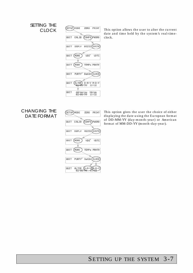
SETTING THECLOCK This option allows the user to alter the current
date and time held by the system’s real-time-clock.
CHANGING THEDATE FORMAT
This option gives the user the choice of eitherdisplaying the date using the European formatof DD-MM-YY (day-month-year) or Americanformat of MM-DD-YY (month-day-year).
SETTING UP THE SYSTEM 3-7

SELECT APRINTER TYPE
Both the ADP220 and ADS220 instrumentscan send reading data to a printer. TheADS220 requires a printer with at least 40columns across the page but the ADP220 canalso be formatted for a narrower, 24 columnprinter. Both instruments have the option toselect "no printer". In this case the PRINTbutton will not be displayed. The "printer type"can be set to...
none
24 column (ADP Only)
or 40+ column
none will disable the printer output and should be selected if a printerwill not be used.
24 column should be selected if a Datac 24 column printer (B&S code55-02U) or similar is to be used. If the printer has a print width of 40 ormore columns, then select 40+ column.
The printout formats vary depending on the instruments setup and theprinter type selected.
SELECTPRINTER PORT
Both the ADP220 and ADS220 have the optionto redirect the printed outputs to one of twoports. Pressing the PORT button will alternatethe "printer port" option between...
Serial 1
and Parallel
3-8 SETTING UP THE SYSTEM

User Defined Temperature Compensation
The ADP220 and ADS220 both incorporate a User Defined Temperature Compensation mode. It enablesthe instrument to automatically correct for samples other than sucrose and Quartz Control Plates withknown temperature coefficients. Temperature corrections are made using the following linear equation.
where r = displayed corrected readingx = uncorrected reading in Selected Scale UnitsA = sample temperature coefficient in Selected Scale Units / °Ct = temperature of active probe in °C
Note: The entered coefficient must be in the same units as the selected scale.
SETTING THEUSER DEFINEDTEMPERATURECOEFFICIENT
CONSTANT
The entered coefficient constant must be in thesame units as the selected scale.
For example, if the selected scale is °z then thecoefficient constant must have units of
°z / °C
SELECTING THEUSER DEFINEDTEMPERATURE
COMPENSATIONMODE
To use the user defined temperature compensation select the uctemperature compensation mode from the MODE menu. (See page 2-6for more details)
After quitting from the MODE menu, the instrument will return back tothe main display and subsequent displayed readings will be correctedusing the UDTC equation.
SETTING UP THE SYSTEM 3-9

User Defined ScalesADP220 Polarimeter Only
The ADP220 Series polarimeters can incorporate up to seven measurement scales, degrees angular, ISS,and five user definable scales. Pressing MODE, SCALE, as described on page 2-5, will step through the2 permanent scales (°a, and °z) and any of the 5 definable scales that have been set.
CREATE ASPECIAL
USERDEFINED
SCALE
The sequence to enter special scale DATAshown on the left, enables the operator to typein a scaling factor constant for each userdefined scale.
Press UP or DOWN until the appropriate➧
User Scale (A,B,C,D,E) is displayed andpress SLCT.
Enter the value for scaling factor constant➧
A (see "Entering a number" on page 2-2 forinformation on numeric entry).
The first of two scale identification➧
characters can then be entered. This caneither be 0 to 9, by pressing theappropriate numeric key, or a letter, bypressing UP/DOWN and then SLCT.
Then enter the second identification➧
character.
The polarimeter is basically calibrated in angular degrees. A single scalingfactor constant is then used to convert the readings to the user definedscale units as shown below:-
u = Ax
where u = reading in user unitsx = degrees angularand A the scaling factor constant
3-10 SETTING UP THE SYSTEM

CANCEL AUSER
DEFINEDSCALE
If any of the five User Defined Scales are notrequired for normal use, they can be removedfrom the SCALE selection list using thesequence shown on the left.
Press UP or DOWN until the appropriate➧
User Scale (A,B,C,D,E) is displayed andpress SLCT.
If all five User Defined Scales are Cancelled,then pressing SCALE will select only degrees angular (°a) or degreesangular ISS (°z).
SETTING UP THE SYSTEM 3-11

Purity Settings & OperationADS220 Saccharimeter Only
The ADS220 has the facility to automatically calculate the purity of sugar solutions. The value of purityis derived from the angular rotation of the sample (supplied by the saccharimeter), the massconcentration (brix) value (supplied by a refractometer) and the density (derived from the brix value).The refractometer reading can be entered into the ADS220 either manually by entering the valuethrough the ADS220 keypad or automatically if the refractometer is an Bellingham + Stanley RFM300or RFM100 refractometer. As there are different methods used throughout industry for calculatingsugar purity, the ADS220 has a number of settings which allow the instrument to be setup using theappropriate calculation.
The general equation used to calculate sugar purity is shown below.
Where: reading is the polarimeter reading in degree Z.purityconst is a user definable purity constant.density is calculated as a function of brix in accordance with the ICUMSA
Specification and Standard SPS-4 (1994).brix is the brix value of the sample.
PURITYFORMAT
The calculated purity value can be displayed ina number of formats.
The format is selected by entering a numberwhich equals:
the number of integer digits +the number of decimal places x 16.
The default value is 35, which will output thepurity value with 3 integer digits and 2 decimalplaces.
A list of alternatives is shown below.
Alternative Purity Format Values
Value Description Example
50 2 integer, 3decimal places
12.346
35 3 integer, 2decimal places
123.45
20 4 integer, 1decimal places
1234.5
5 5 integer, 0decimal places
12345
3-12 SETTING UP THE SYSTEM
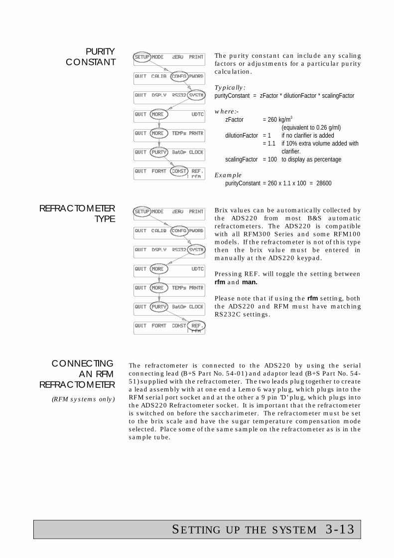
PURITYCONSTANT
The purity constant can include any scalingfactors or adjustments for a particular puritycalculation.
Typically:purityConstant = zFactor * dilutionFactor * scalingFactor
where:-zFactor = 260 kg/m3
(equivalent to 0.26 g/ml)dilutionFactor = 1 if no clarifier is added
= 1.1 if 10% extra volume added withclarifier.
scalingFactor = 100 to display as percentage
ExamplepurityConstant = 260 x 1.1 x 100 = 28600
REFRACTOMETERTYPE
Brix values can be automatically collected bythe ADS220 from most B&S automaticrefractometers. The ADS220 is compatiblewith all RFM300 Series and some RFM100models. If the refractometer is not of this typethen the brix value must be entered inmanually at the ADS220 keypad.
Pressing REF. will toggle the setting betweenrfm and man.
Please note that if using the rfm setting, boththe ADS220 and RFM must have matchingRS232C settings.
CONNECTINGAN RFM
REFRACTOMETER(RFM systems only)
The refractometer is connected to the ADS220 by using the serialconnecting lead (B+S Part No. 54-01) and adaptor lead (B+S Part No. 54-51) supplied with the refractometer. The two leads plug together to createa lead assembly with at one end a Lemo 6 way plug, which plugs into theRFM serial port socket and at the other a 9 pin ’D’ plug, which plugs intothe ADS220 Refractometer socket. It is important that the refractometeris switched on before the saccharimeter. The refractometer must be setto the brix scale and have the sugar temperature compensation modeselected. Place some of the same sample on the refractometer as is in thesample tube.
SETTING UP THE SYSTEM 3-13
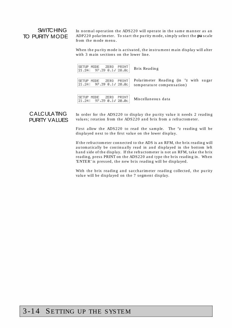
SWITCHINGTO PURITY MODE
In normal operation the ADS220 will operate in the same manner as anADP220 polarimeter. To start the purity mode, simply select the pu scalefrom the mode menu.
When the purity mode is activated, the instrument main display will alterwith 3 main sections on the lower line.
Brix Reading
Polarimeter Reading (in °z with sugartemperature compensation)
Miscellaneous data
CALCULATINGPURITY VALUES
In order for the ADS220 to display the purity value it needs 2 readingvalues; rotation from the ADS220 and brix from a refractometer.
First allow the ADS220 to read the sample. The °z reading will bedisplayed next to the first value on the lower display.
If the refractometer connected to the ADS is an RFM, the brix reading willautomatically be continually read in and displayed in the bottom lefthand side of the display. If the refractometer is not an RFM, take the brixreading, press PRINT on the ADS220 and type the brix reading in. When’ENTER’ is pressed, the new brix reading will be displayed.
With the brix reading and saccharimeter reading collected, the purityvalue will be displayed on the 7 segment display.
3-14 SETTING UP THE SYSTEM

ADP Key Function Map
Print thedisplayed reading
Zero theinstrument
Change passwords
Select multiplier,scale & temp. comp.
Set response mode andreading resolution Enter UDTC
constant.
Configure the RS232 port.
Select printertype Cancel a
selectedUDS
Enter UDSscalingconstants
Setclock
Set batch andoperatorvariable
Enter SPAN aim valueand wait for correction.
Selecttemperaturescale
Select sample or chamberprobe for temperaturecompensation
SETTING UP THE SYSTEM 3-ADP


ADS Key Function Map
Print thedisplayed reading
Zero theinstrument
Change passwords
Select multiplier,scale & temp. comp.
Set response mode andreading resolution Enter UDTC
constant.
Select printertype
Setclock
Set batch andoperatorvariable
Set purity format,constant & refractometer mode
Enter SPAN aim valueand wait for correction.
Selecttemperaturescale
Select sample or chamberprobe for temperaturecompensation
SETTING UP THE SYSTEM 3-ADS


S E C T I O N 4
Error Conditions & Messages
Printing 4-1System Lockup 4-1Memory Corruption 4-1Setting Default Values 4-2
ERROR CONDITIONS & MESSAGES 4


Error Conditions & Messages
PRINTING When data is sent to the printer by pressing PRINT, the characters areplaced in an output buffer and are removed by the printer when it isready. If there is not a printer connected or the printer is "off-line", thenthe characters remain in the buffer and a message will be displayed,requesting you to select retry or quit. When the printer is ready to print,press retry. Pressing quit will cancel the print and return to the mainmenu.
SYSTEMLOCKUP
If at any time the instrument fails to respond to the soft keys or producesnonsensical displays, press SYSTEM RESET or switch the power off, thenon again.
MEMORYCORRUPTION
Most of the numbers and values used in the polarimeter calculations arestored in volatile memory, i.e. when the instrument is switched off, thevalues are lost. There are some values, however, that must be retainedeven when the power is removed and these are held in a special, non-volatile memory. The instrument checks this stored data during switch-on initialisation and when the data is saved following a change inconfiguration. If an error is detected, a warning message will bedisplayed, similar to the screen shown below.
The user should press any key and theoperation will continue.
The user should then contact the B&S Service Department.
When contacting B&S Service Department, please have the followinginformation ready:-
a. Instrument serial number (on label at the rear of the instrumenthousing).
b. Software version (see page 3-1).
c. Error code.
ERROR CONDITIONS & MESSAGES 4-1

SETTINGDEFAULTVALUES
If the instrument fails to start up correctly after switching on, then itcould be advisable to reset certain settings to the original factory set (ordefault) values. Switch the instrument off. Press, and hold down, the 9key and switch on. Do not release the key until the screen shows ...
Selecting YES will set:-Response slowDisplay resolution highReading multiplication factor 1.0 (off)Operator Password 123Supervisor Password 135RS232 serial conditions 9600, 8-bit, npDate format DD-MM-YYBatch & Operator codes 0 (none)Printer port parallelUser defined t.c. constant 0Temperature scale °CActive temperature probe chamber
ADP220Selected scale °aSelected temperature compensation nc°a range -85° to +85°Scale selection list °a, °z onlyPrinter type 24 column
ADS220Selected scale °zSelected temperature compensation sc°a range -85° to +85° (fixed)Scale selection list °a, °z, pu onlyPrinter type 40+ columnPurity constant 28617.6Purity format 35 (2 decimal places)
After pressing YES or NO, the next screen will be displayed ...
Selecting YES will set:-Span setting factory settingLast span value --:-- --/--/--
ADP220Span aim value 33.60
ADS220Span aim value 100.00
4-2 ERROR CONDITIONS & MESSAGES
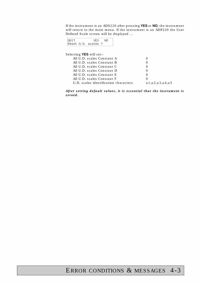
If the instrument is an ADS220 after pressing YES or NO, the instrumentwill return to the main menu. If the instrument is an ADP220 the UserDefined Scale screen will be displayed ...
Selecting YES will set:-All U.D. scales Constant A 0All U.D. scales Constant B 0All U.D. scales Constant C 0All U.D. scales Constant D 0All U.D. scales Constant E 0All U.D. scales Constant F 0U.D. scales identification characters u1,u2,u3,u4,u5
After setting default values, it is essential that the instrument iszeroed.
ERROR CONDITIONS & MESSAGES 4-3


S E C T I O N 5
Specification
Performance 5-1Temperature 5-1Light Source 5-1Interface Ports 5-1Physical 5-2Power Requirements 5-2
SPECIFICATION 5


Specification
PERFORMANCE ADP 220
Scale °Z (ISS) °Angular
Range -30 to +120 -85 to +85
Resolution 0.01 0.01
Accuracy (Sucrosesolution @ 20°C)
± 0.05 ± 0.02
ADS 220
Scale °Z (ISS)
Range -225 to +225
Resolution 0.01
Accuracy (Sucrose solution @ 20°Cand over the range -30 to +120°Z)
± 0.03
TEMPERATURE Ambient . . . . . . . . . . . . . . . . . . . . . . . . . . . . . . . . . 5 to 45°CStorage . . . . . . . . . . . . . . . . . . . . . . . . . . . . . . . . -5 to 60°C
LIGHT SOURCE Type . . . . . . . . . . . . . . . . . . . . L.E.D. with interference filterNominal Wavelength . . . . . . . . . . . . . . . . . . . . . . . . . 589nm
INTERFACE SerialType . . . . . . . . . . . . . . . . . . . . . . . . . . . . . . . . . . . . RS232CBaud rate . . . . . . . . . . . . . . . . . . . . . . . . . 300, 1200 or 9600Word structure . . 7 bit with even parity or 8 bit with no parityHandshaking . . . . . . Combined DSR/DTR type + XON/XOFF
RefractometerType . . . . . . . . . . . . . . . . . . . . . . . . . . . . . . . . . . . . RS232CBaud rate . . . . . . . . . . . . . . . . . . . . . . . . . . . . . . . . . . . 9600Word structure . . . . . . . . . . . . . . . . . . . . 8 bit with no parityHandshaking . . . . . . Combined DSR/DTR type + XON/XOFF
ParallelType . . . . . . . . . . . . . . . . . . . . . "Centronics" printer output
SPECIFICATION 5-1

PHYSICALDepth . . . . . . . . . . . . . . . . . . . . . . . . . . . . . . . . . . . 280mmWidth . . . . . . . . . . . . . . . . . . . . . . . . . . . . . . . . . . . . 550mmHeight . . . . . . . . . . . . . . . . . . . . . . . . . . . . . . . . . . . 150mmWeight . . . . . . . . . . . . . . . . . . . . . . . . . . . . . . . . . . . . 8.0Kg
POWERREQUIREMENTS
Power Supply type 55-104Voltage . . . . . . . . . . . . . . . . . . . . . . . . . 110 to 230V~ ±10%Frequency . . . . . . . . . . . . . . . . . . . . . . . . . . . . . 50 to 60 HzMax. load . . . . . . . . . . . . . . . . . . . . . . . . . . . . . . . . . . 60 mA
5-2 SPECIFICATION

S E C T I O N 6
Spares & Accessories
Spare Parts 6-1Power Supplies 6-1Optional Accessories 6-1Miscellaneous 6-1Sample Tubes 6-1
SPARES & ACCESSORIES 6


Spare Parts
DescriptionUK
Version230V
EuroVersion
230V
USVersion
110V
POWERSUPPLIES
Power supply unit (all instruments) 55-104
Mains leads (for use with 55-104) 61-191 61-193 61-192
OPTIONALACCESSORIES
Quartz Control Plate nominal 97°Z (33°Angular) 34-10
Quartz Control Plate nominal 15°Z (5°Angular) 34-11
Serial printer interface cable - 25way "D" type 54-02
Parallel printer interface cable - 36way "Centronics" 54-03
PC adaptor (for use with 54-02) 54-51
24 column printer package including power supply(for use with interface cable 54-02) (ADP220 only)
55-02U 55-02E 55-02S
40 column printer package including power supplyand interface cable 54-03
55-09U 55-09E 55-09S
MISCELLANEOUS Operators manual (English) 36-102
Operators manual (Spanish) 36-111
Operators manual (French) 36-112
Operators manual (German) 36-113
ADP220 Utility software (for remote operation andUser Defined Scale creation)(for use on a PC with Windows 95 or NT)
36-251
Description Tube Length 100mm 200mm
SAMPLETUBES
Standard glass sample tube 35-29 35-30
Straight centre filling glass tube 35-46 35-47
Cup-shaped centre filling glass tube 35-57 35-58
Centre filling glass tube fitted with water jacket 35-02 35-03
Funnel flow through tube with water jacket 36-51 36-52
Continuous flow through tube with water jacket 36-61 36-62
Tubes for special applications and with reducedinternal diameter are also available on application.
(Contact B+S)
SPARES & ACCESSORIES 6-1
