the physics and properties of free-electron lasers · the physics and properties of free -electron...
TRANSCRIPT

BNL - 69298
The Physics and Properties of Free-Electron Lasers
S. Krinsky National Synchrotron Light Source Brookhaven National Laboratory
P.O. Box 5000 Upton, NY, USA 11973-5000
June 2002
National Synchrotron Light Source
Brookhaven National Laboratory Operated by
Brookhaven Science Associates Upton, NY 11973
Under Contract with the United States Department of Energy Contract Number DE-AC02-98CH10886
DISCLAIMER
This report was prepared as an account of work sponsored by an agency of the United States Government. Neither the United States Government nor any agency thereof, nor any of their employees, nor any of their contractors, subcontractors or their employees, makes any warranty, express or implied, or assumes any legal liability or responsibility for the accuracy, completeness, or any third party’s use or the results of such use of any information, apparatus, product, or process disclosed, or represents that its use would not infringe privately owned rights. Reference herein to any specific commercial product, process, or service by trade name, trademark, manufacturer, or otherwise, does not necessarily constitute or imply its endorsement, recommendation, or favoring by the United States Government or any agency thereof or its contractors or subcontractors. The views and opinions of authors expressed herein do not necessarily state or reflect those of the United States Government or any agency thereof.
The Physics and Properties of Free-Electron Lasers
Samuel Krinsky
Brookhaven National Laboratory, Upton, NY 11973
Abstract. We present an introduction to the operating principles of free-electron lasers, discussing the amplification process, and the requirements on the electron beam necessary to achieve desired performance.
INTRODUCTION
In the storage rings of synchrotron radiation facilities, the electrons are radiating incoherently [1,2]. Since there is no multi-particle coherence, the radiated intensity is linearly proportional to the number of electrons Ne. If the electrons in a beam are spatially bunched on the scale of the radiation wavelength [3,4], coherent radiation with intensity proportional to Ne
2 will be emitted. Since Ne can be very large, coherent emission offers the potential of greatly enhancing the intensity. The technical challenge is to produce the required bunching on the scale of the radiation wavelength. A task that increases in difficulty as the wavelength is decreased.
To obtain coherent emission at short wavelengths, one must develop methods to bunch the electron beam utilizing the radiation. One approach that has already been successfully applied down to the vacuum ultraviolet is the free electron laser (FEL). The FEL [5] is based on a resonant interaction between an electromagnetic wave and an electron beam traveling along the axis of an undulator magnet. The periodic undulator magnetic field produces a transverse component of the electron velocity that couples the energy of the electron to that of the wave. Under general conditions this coupling will merely result in a shifting of energy back and forth between the electron beam and the radiation. However, in resonance, there can be sustained energy transfer from the electrons to the wave. FELs are reviewed in refs. [6-8].
In designing an FEL, one must decide on the type of electron accelerator to be used: e.g. storage ring [9], room temperature linac [10], or superconducting linac [11]. Storage rings provide very high stability and continuous operation; however, the FEL action perturbs the electron beam, thus limiting performance. The development of photocathode RF electron guns [12,13] has made linacs attractive as drivers for FELs. They can produce high peak current and small normalized emittance. The microbunch pulse length in photo- injectors is typically on the order of 10 ps, and bunch compression can be used to reduce the pulse length down to the vicinity of 100 fs. The macropulse structure in room temperature linacs consists of pulse trains separated
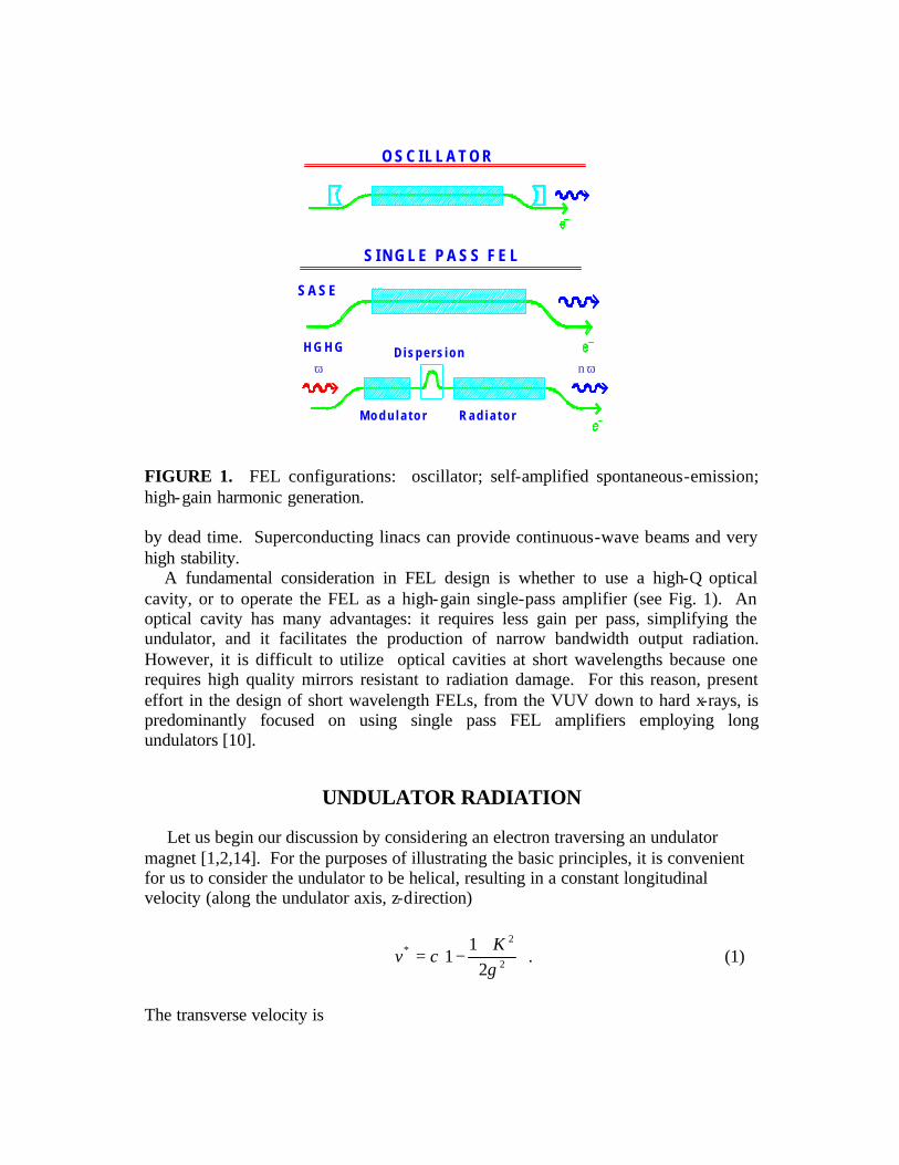
FIGURE 1. FEL configurations: oscillator; self-amplified spontaneous-emission; high-gain harmonic generation. by dead time. Superconducting linacs can provide continuous-wave beams and very high stability.
A fundamental consideration in FEL design is whether to use a high-Q optical cavity, or to operate the FEL as a high-gain single-pass amplifier (see Fig. 1). An optical cavity has many advantages: it requires less gain per pass, simplifying the undulator, and it facilitates the production of narrow bandwidth output radiation. However, it is difficult to utilize optical cavities at short wavelengths because one requires high quality mirrors resistant to radiation damage. For this reason, present effort in the design of short wavelength FELs, from the VUV down to hard x-rays, is predominantly focused on using single pass FEL amplifiers employing long undulators [10].
UNDULATOR RADIATION
Let us begin our discussion by considering an electron traversing an undulator magnet [1,2,14]. For the purposes of illustrating the basic principles, it is convenient for us to consider the undulator to be helical, resulting in a constant longitudinal velocity (along the undulator axis, z-direction)
+−= 2
2*
21
1γK
cv . (1)
The transverse velocity is
O S C I L L A T O R
S I N G L E P A S S F E L
S A S E
D i s p e r s i o nn ωω
H G H G
M o d u l a t o r R a d i a t o r
+−=
→
zkyzkxcK
v wwT sincos^^
γ. (2)
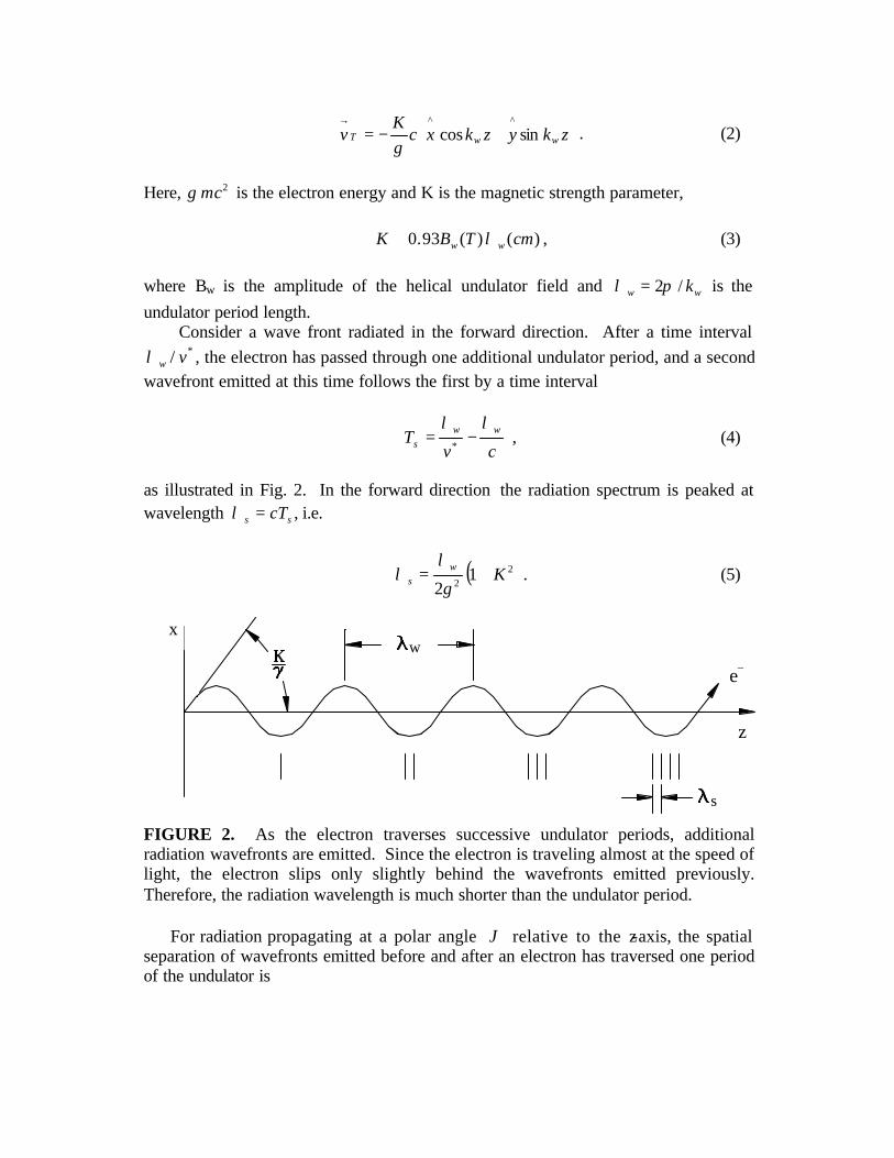
Here, 2mcγ is the electron energy and K is the magnetic strength parameter, )()(93.0 cmTBK ww λ≅ , (3) where Bw is the amplitude of the helical undulator field and ww k/2πλ = is the undulator period length. Consider a wave front radiated in the forward direction. After a time interval
*/ vwλ , the electron has passed through one additional undulator period, and a second wavefront emitted at this time follows the first by a time interval
cv
T wws
λλ−=
* , (4)
as illustrated in Fig. 2. In the forward direction the radiation spectrum is peaked at wavelength ss cT=λ , i.e.
( )22
12
Kws +=
γ
λλ . (5)
xw
s
z
e−
FIGURE 2. As the electron traverses successive undulator periods, additional radiation wavefronts are emitted. Since the electron is traveling almost at the speed of light, the electron slips only slightly behind the wavefronts emitted previously. Therefore, the radiation wavelength is much shorter than the undulator period. For radiation propagating at a polar angle ϑ relative to the z-axis, the spatial separation of wavefronts emitted before and after an electron has traversed one period of the undulator is
( )2222
12
)( ϑγγ
λϑλ ++= Kw
s . (6)
In an undulator with Nw periods, the radiated pulse from one electron has a pulse length of swN λ . Consequently, the line width at fixed observation angle is
ws N
1≅
∆λ
λ. (7)
From Eq. (6), we see that the spectral broadening due to accepting radiation in a cone of half-angle ϑ∆ about the forward direction is )1/()(/ 222 Ks +∆=∆ ϑγλλ . This broadening will be small only if wϑϑ <∆ , where we define
w
s
ww LN
K λ
γϑ =
+≡ 2
2
21
, (8)
with www NL λ= . Angle wϑ characterizes the central cone of the undulator radiation. The power per unit solid angle per unit frequency emitted in the forward direction at
ss c λπωω /2== by an electron beam of energy γ and current Ie traversing Nw
periods is given by [1] (mks units, Alfven current AmpemcI oA 000,17/4 3 ≅= επ )
JNmcdd
dP
s
ww
SPONT
Nwλ
λ
ω22=
Ω,
A
e
II
KK
J2
2
1+= . (9)
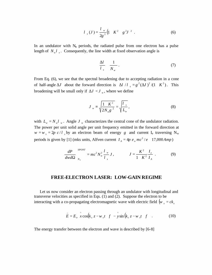
FREE-ELECTRON LASER: LOW-GAIN REGIME
Let us now consider an electron passing through an undulator with longitudinal and transverse velocities as specified in Eqs. (1) and (2). Suppose the electron to be interacting with a co-propagating electromagnetic wave with electric field ( )ss ck=ω
( ) ( )
+−−+−=
→
φωφω tzkytzkxEE sssso sincos^^
. (10)
The energy transfer between the electron and wave is described by [6-8]
( )φζγγ
γ+−==
→→→
)(cos23
zmceKE
Evmce
dzd oo , (11)
where the ponderomotive phase is )()()( ztzkkz sws ωζ −+≡ . (12) Here, t(z) is the time of arrival of the electron at position z along the undulator axis. Differentiating Eq. (12), we find
*v
kkdzd s
ws
ωζ−+= (13)
The condition for resonance is
sw
ws
s
vvc
kkv
dzd
λλωζ
=−→+
=→=*
** )(0 . (14)
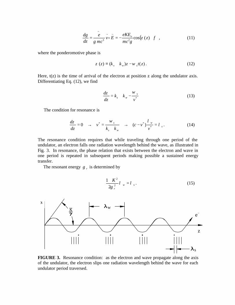
The resonance condition requires that while traveling through one period of the undulator, an electron falls one radiation wavelength behind the wave, as illustrated in Fig. 3. In resonance, the phase relation that exists between the electron and wave in one period is repeated in subsequent periods making possible a sustained energy transfer. The resonant energy rγ is determined by
swr
Kλλ
γ=
+2
2
21
. (15)
x
e−
z
w
s
FIGURE 3. Resonance condition: as the electron and wave propagate along the axis of the undulator, the electron slips one radiation wavelength behind the wave for each undulator period traversed.
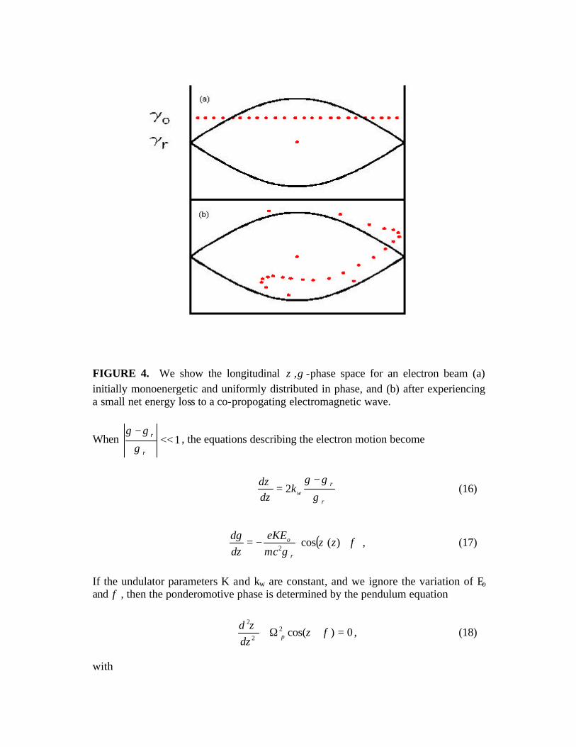
FIGURE 4. We show the longitudinal γζ , -phase space for an electron beam (a) initially monoenergetic and uniformly distributed in phase, and (b) after experiencing a small net energy loss to a co-propogating electromagnetic wave.
When 1<<−
r
r
γ
γγ, the equations describing the electron motion become
r
rwk
dzd
γ
γγζ −= 2 (16)
( )φζγ
γ+−= )(cos
2z
mceKE
dzd
r
o , (17)
If the undulator parameters K and kw are constant, and we ignore the variation of Eo and φ , then the ponderomotive phase is determined by the pendulum equation
0)cos(22
2
=+Ω+ φζζ
pdzd
, (18)
with
22
02 2
r
wp mc
KEekγ
=Ω . (19)
This is an appropriate description in the low-gain regime, when amplification of the wave in a single pass through the undulator is small. For an electron beam which is initially monoenergetic and uniformly distributed in phase, an illustration of net energy loss by the electron beam to the radiation is presented in Fig. 4. When the gain per pass is small, a large total gain can be achieved by placing the undulator between the mirrors of an optical resonator. If the electron beam is comprised of a long train of bunches, with neighboring bunches space by twice the length of the optical cavity, the radiation can be repeatedly amplified as it interacts with successive bunches.
FREE-ELECTRON LASER: HIGH-GAIN REGIME
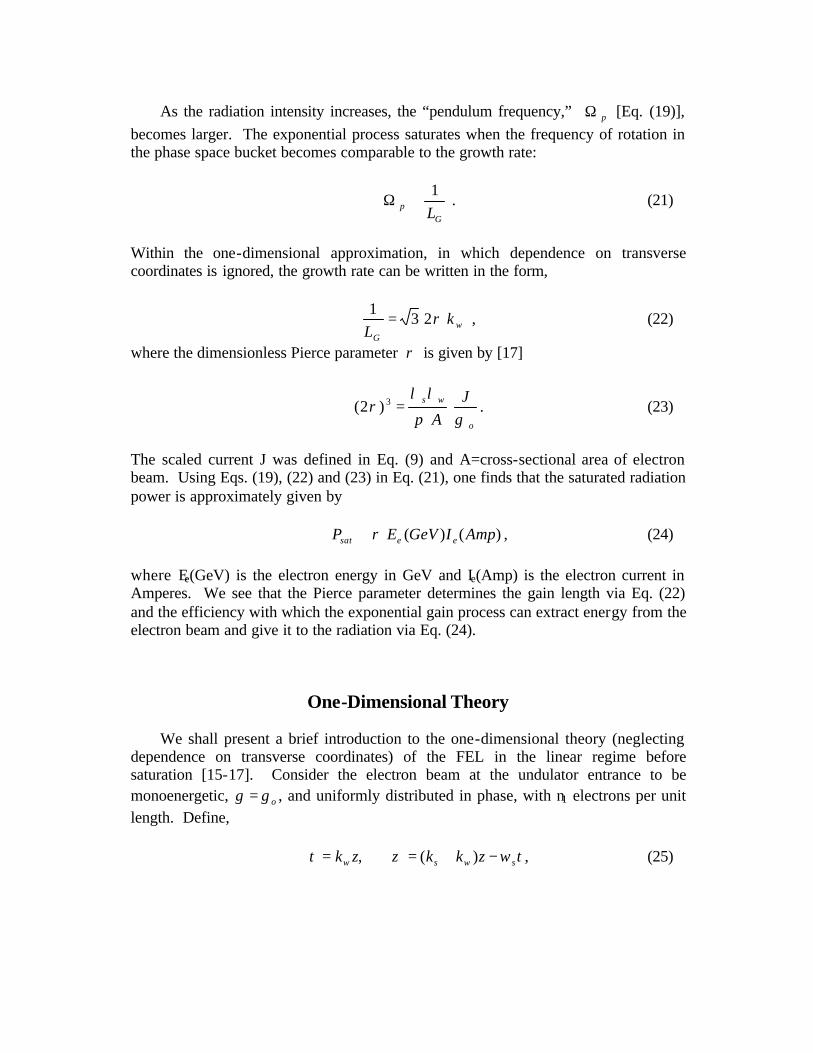
It is difficult to use optical cavities at short wavelengths because of the need for high-quality mirrors resistant to radiation damage. Therefore, to generate short wavelength radiation, high-gain single pass amplifiers employing long undulators are of interest. The mathematical description of high-gain amplifiers [6-8, 15-17] must take into account the variation of the radiation field. High gain results from a collective instability leading to exponential growth of the radiated power, )/exp( GLzP ∝ , (20) where LG is the e- folding or gain length (see Fig. 5). The mechanism leading to exponential growth is as follows: Electrons gain or lose energy depending upon their phase ζ with respect to the electromagnetic wave. The resulting energy modulation of the electron beam gives rise to a spatial bunching due to the dispersion in the undulator (i.e. *v larger for higher-energy electrons). The density modulation at the radiation wavelength then produces enhanced coherent emission, amplifying the radiation intensity. The positive feedback loop is closed since the increase in radiation intensity enhances the energy modulation of the electron beam. Suppose the electron beam entering the undulator is initially monoenergetic with energy oγ , and uniformly distributed in phase, and there exists a small coherent laser seed. An illustration [7] of the evolution of the electron beam’s longitudinal phase space distribution and the corresponding increase of the radiation field amplitude is presented in Fig. 6.
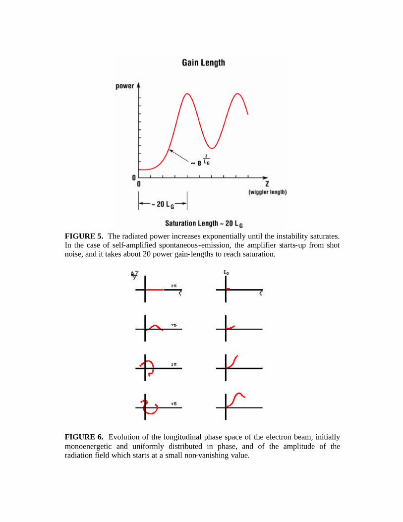
FIGURE 5. The radiated power increases exponentially until the instability saturates. In the case of self-amplified spontaneous-emission, the amplifier starts-up from shot noise, and it takes about 20 power gain- lengths to reach saturation.
FIGURE 6. Evolution of the longitudinal phase space of the electron beam, initially monoenergetic and uniformly distributed in phase, and of the amplitude of the radiation field which starts at a small non-vanishing value.
As the radiation intensity increases, the “pendulum frequency,” pΩ [Eq. (19)], becomes larger. The exponential process saturates when the frequency of rotation in the phase space bucket becomes comparable to the growth rate:
G
p L1
≅Ω . (21)
Within the one-dimensional approximation, in which dependence on transverse coordinates is ignored, the growth rate can be written in the form,
wG
kL
ρ231
= , (22)
where the dimensionless Pierce parameter ρ is given by [17]
o
ws JA γπ
λλρ =3)2( . (23)
The scaled current J was defined in Eq. (9) and A=cross-sectional area of electron beam. Using Eqs. (19), (22) and (23) in Eq. (21), one finds that the saturated radiation power is approximately given by )()( AmpIGeVEP eesat ρ≅ , (24) where Ee(GeV) is the electron energy in GeV and Ie(Amp) is the electron current in Amperes. We see that the Pierce parameter determines the gain length via Eq. (22) and the efficiency with which the exponential gain process can extract energy from the electron beam and give it to the radiation via Eq. (24).
One-Dimensional Theory
We shall present a brief introduction to the one-dimensional theory (neglecting dependence on transverse coordinates) of the FEL in the linear regime before saturation [15-17]. Consider the electron beam at the undulator entrance to be monoenergetic, oγγ = , and uniformly distributed in phase, with n1 electrons per unit length. Define, tzkkzk swsw ωζτ −+== )(, , (25)
where )1/(2/ 220 Kkck wss +== γω . Introduce the line density ≡Λ ),( τζ the number
of electrons per unit length, and the energy deviation ( ) oop γγτζγτζ /),(2),( −≡ , and write the radiated electric field in the form
+= −
→)(
^^
)(Re tzki sseEyixE ω . (26)
The slowly varying complex amplitude φioeEE ≡ [see Eq. (10)].
Let us suppose the line density, energy deviation and the electric field amplitude have small sinusoidal perturbations: ζττζ )1(
1 )(),( qiq en +Λ+≅Λ , (27)
ζτζτζ )1(),(),( qi
q epp +≅ , (28) ζττζ iq
q eEE )(),( ≅ , (29) where ssq ωωω /)( −= is the frequency detuning. We keep only terms linear in the perturbations. The variation in the electron energy deviation due to the radiated electric field is described by Eq. (11). Neglecting the non-resonant *
qE term, one finds
qo
q Edp
222
γτ−=
∂
∂. (30)
The change in the density modulation resulting from the energy modulation of the electron beam is given by the equation of continuity [ ]0)( =∂Λ∂+∂Λ∂ ζτ p . Linearizing, one derives
qq pnqi 1)1( +−=
∂
Λ∂
τ. (31)
The increment in the electric field driven by the density modulation is determined by the one-dimensional paraxial wave equation
qo
q
dEiq Λ=
+
∂∂
γτ1 , (32)
where (mks units)
,2
,2 221 mck
eKd
AkeK
dwow
==ε
(33)

and A is the cross-sectional area of the electron beam. Eqs. (30), (31) and (32) imply
,)2)(1( 32
2
qq EqiEiq ρττ
+=
+
∂∂
∂∂
(34)
with 3
1213 /2)2( ondd γρ = , the Pierce parameter introduced in Eq. (23).
The solution to Eq. (34) has the form ττττ 321
321)( sssq eaeaeaE ++= (35)
where the coefficients a1,a2,a3 are determined from the initial conditions
),0(),0( qqE Λ and 0)0( =qp . The Laplace transform parameters 321 ,, sss are the solutions of the cubic dispersion relation .)2()( 32 ρiiqss =+ (36) A useful approximation is
−
−≅
2
291
232
ρµρµρ
qqis . (37)
There are three modes: growing; decaying and oscillating; corresponding to
.,22
3,
223
iii
−+−+=µ For the exponentially growing mode,
.29
11
23
)2(Re2
1
−≅
ρρ
qs (38)
It can now be shown that the evolution of the electric field is determined by [18-19,23]
),0()()0()()( 1)1()2(q
oqqqq
dHEHE Λ+=
γτττ (39)
where the transfer functions are given by (m=1,2)
.))(())(())((
)(2313
3
1232
2
3121
1)(321
sssses
sssses
sssses
Hsmsmsm
mq −−
+−−
+−−
=τττ
τ (40)

FIGURE 7. Plot of 1)(
2)2( −zkH wq versus ρ2/q , for: (a) zkwρ2 = 0.5;
(b) zkwρ2 = 1.0; (c) zkwρ2 = 10. For low gain (a), the interference of the three modes is important. In the high-gain regime (c), the growing mode dominates. In the exponential-gain regime the growing mode dominates (see Fig. 7) and
.)2(91
)( /2/422)( 222Gs Lzqmm
q eeH ωσωρτ −−≅ (41)
The power gain length, GL , has the value given in Eq. (22), and the gain bandwidth is
τ
ρωσ ω
33s= . (42)
Self-Amplified Spontaneous-Emission (SASE)
In the absence of an external seed laser, 0)0( =qE , so the FEL amplifier starts up from the shot noise in the electron beam [18-23],
∑ +=Λj
tqisq
jsek )0()1(
2)0( ω
π. (43)
Here, the sum is over the electrons comprising the beam and )0(jt is the arrival time of the jth electron at the undulator entrance. It follows from Eq. (39), that
∑ +=j
tqi
o
sqq
jsekd
HE )0()1(1)1(
21
)()( ω
πγττ . (44)
We can treat the arrival times )0(jt as independent random variables. Therefore,
at a fixed position, zkw=τ , along the undulator, )(τqE and its Fourier transform ),( ζτE are sums of independent random terms. It follows from the Central Limit
Theorem [24] that the probability distribution describing the spectral intensity 2
qEI ∝ , or the time-domain intensity 2
EI ∝ , is the negative exponential
distribution
III e
IIp /1)( −= . (45)
The intensity fluctuation is 100%. The output intensity as a function of time exhibits spiking [25] (see Fig. 8), and the width of the intensity peaks are characterized by the coherence time [24,26]
ωσπ /=cohT . The spectral intensity also exhibits spikes (Fig. 9), and their widths are inversely proportional to the electron bunch duration bT . Let us consider the energy in a single SASE pulse,
∫∝bsT
dEWω
ζτζτ0
2),()( . (46)
For fixed τ , the pulse can be divided up into M statistically independent time-intervals of width Tcoh . The fluctuation within a single coherent region is 100%, but the fluctuation Wσ of the energy in the entire pulse is reduced and given by [24,26]
( )
b
cohW T
TMW
WW==
−=
12
2
2σ . (47)

FIGURE 8. Intensity spiking in the time-domain. The width of the peaks is characterized by the SASE coherence time ωσπ /=cohT .
bT
I ( )
1
< I ( ) >
cohT1
FIGURE 9. Intensity spiking in the frequency-domain. In the single-shot spectrum shown on the left, the width of the peaks is inversely proportional to the electron bunch duration Tb. The average of many SASE pulses is illustrated on the right, and in this case the width is proportional to the gain bandwidth cohT/πσ ω = .
The energy per pulse is described by the gamma distribution [24],
−
Γ=
−
WW
MWW
WM
MWp
MM
W exp1
)()(
1
. (48)
It follows from Eqs. (41) and (44) that the average output SASE power spectrum can be expressed in the form [20]
Gs LzD
NoiseInput
eeddP
ddP
ddP /2/)(
122
91
ωσωω
ωωω−−
−
+
= , (49)
where
π
γρ
ω 2
21 mc
ddP o
D
Noise
=
−
, (50)
arises from the shot noise in the electron beam and ( ) InputddP ω represents an input laser seed. In the case of SASE (no seed), the average output power is [18,19]
GLz
coh
sat eN
PP /
291
= . (51)
Psat is the saturation power defined in Eq. (24) and cohcoh cTnN 1= is the number of electrons in a coherence length. Typically, cohN is large, and it takes about 20 SASE gain lengths to reach saturation (Fig. 5). The noise (within the one-dimensional approximation) amplified in SASE is the spontaneous undulator radiation with frequency sωω = emitted in the first two power
gain lengths into a cone of solid angle As /2λ about the forward direction (A being the cross-sectional area of the electron beam). This follows from observing that [22]
SPONT
LN
sD
Noise wGwdd
dPAd
dP
λω
λ
ω/2
21
43
=
−
Ω
=
, (52)
which can be verified from Eqs. (9), (22) and (23).
Constraints On Electron Beam Quality
To achieve high gain, the resonant condition must hold for most electrons. This imposes tolerances on the energy spread and emittance. On should note that, as illustrated in Fig. 2, since the electrons are traveling almost at the speed of light, the radiation emitted by an electron moves ahead of it by only one radiation wavelength for each undulator period traversed. Therefore, an electron can influence only those electrons less than one slippage distance, sWN λ in front of it. Tolerances to assure desired gain restrict the properties of the electron beam within a slice shorter than one slippage distance. To assure the entire electron beam contributes, tolerances must be imposed on the entire beam. Recall from Eq. (15), that the resonance condition is
swr
Kλλ
γ=
+2
2
21
. (53)
Suppose an electron has energy γδγγ += r . In this case, while traversing one
undulator period, the electron slips a distance lδλ +s behind the wave:
lδλλγ
+=+
swK
2
2
21
, (54)
where
rs γ
γδλδ 2−≅l . (55)
Let us assume that in order to maintain coherent energy transfer over a section of undulator of length 2LG, it is necessary that
G
s
N4
λδ <l , (56)
where wGG LN λ/2= is the number of undulator periods in two power gain lengths. The significance of the tolerance imposed in Eq. (56) is that no electron will fall more than 90o out of phase with the wave while traversing two power gain lengths. From Eqs. (55) and (56), we see that the tolerance on the energy spread is
Gr N8
1<
γγδ
. (57)
Now consider an electron that has the resonant energy rγ but which is traveling at a small angle ϑ relative to the z-direction. Since such an electron must travel a longer distance to traverse one undulator period, it slips a distance lδλ +s behind the wave:
lδλλϑ
γ+≅
+
+sw
r
K22
1 2
2
2
, (58)
where
wλϑ
δ2
2
=l . (59)
To assure coherent transfer of energy from the electron beam to the wave over two power gain lengths, we again impose the constraint of Eq. (53), resulting in the tolerance
G
s
L4
λϑ < . (60)
In the special case when the horizontal and vertical emittances are equal, εεε == yx ,
and the horizontal and vertical betatron functions are equal, βββ == yx , we can
write βεϑ /22 = so the inequality (60) can be interpreted as a tolerance on the emittance [27]:
G
s
L24βλ
ε < . (61)
Diffraction of radiation out of the electron beam can result in a reduction of gain. The loss of gain [28,21] should be small as long as the Rayleigh range corresponding to the transverse dimensions of the electron beam is long compared to the gain length. For a cylindrical electron beam of radius εβ=R , we can write this condition as Gs Lk 2>εβ . (62) In order to satisfy both Eqs. (61) and (62), we should have GL2>β . Since the gain is larger for higher electron density, the optimum will be near GL2≅β . In the linear regime before saturation, the coupled Vlasov-Maxwell equations have been used to derive a dispersion relation incorporating the effects of the energy spread,
emittance, and focusing of the electron beam and the diffraction and guiding of the radiation. The gain length was expressed in the scaled form1 [29]:
−=
DDDGD
L s
sw
swG ω
ωω
λ
λσ
λεπ
λπ
β
γ ,,,42
21
. (63)
with
2/1
4
=
o
JD
γ. (64)
Here, the scaled current J was defined in Eq. (9), γσ is the fractional energy spread
and βπλ β 2= the betatron wavelength. The scaling function G can be calculated very accurately [29] and the results agree with computer simulations to within 5-10%. This work was later extended in refs. [30-32]. The analytic determination of the gain length makes possible rapid computation, and facilitates FEL design optimization. Let us now briefly discuss the dependence of the FEL parameters on output wavelength sλ . As we reduce sλ , the required transverse emittance ε, as estimated in
Eq. (61), decreases proportionally. Thus, for a given normalized emittance, εγε ≡n , the required energy increases. As the energy is increased, the current must also be increased to prevent the scaling parameter D [Eq. (64)] from becoming too small. Once the energy and wavelength are determined, the undulator period λw and field strength parameter K must be chosen to satisfy the resonance condition of Eq. (5), as well as certain practical and economic constraints. In particular, as one decreases the period, one must also decrease the magnet gap to prevent the field strength parameter from becoming too small. Therefore, the vertical aperture required for the electron beam, and perhaps electron beam diagnostics, limits how small the period can be
1 When the electron beam size is large enough and the angular spread and energy spread are small, the gain length given in Eq. (63) approaches the result of 1-D theory, Eq. (22). In this regime,
3/1
40,,0,
4
≅
ββ λ
λ
επ
λκ
λ
λ
λεπ
DDG wsw
s
,
with
3/1
223
=
Aεπβ
κ .
The area of the electron beam A=no/n1, where no is the peak value (at R=0) of the number of electrons per unit vo lume and n1 is the number of electrons per unit length. For the parabolic transverse distribution, considered in [29], εβπ3=A and .477.≅κ

made. Also, the magnet period must not be made too long, or else the size and cost of the system will become unnecessarily large. In this paper, we have confined our attention to the fundamental frequency. However, near saturation, significant intensity is produced at the low harmonics of the fundamental. We refer the reader to the literature to pursue this interesting subject [33-36].
Some Recent Experiments on FEL Amplifiers In Table 1, we present some of the fundamental parameters for four proof-of-principle SASE experiments which have been carried out over the last few years in the visible and vacuum ultraviolet: TTF1 at DESY [37]; LEUTL at ANL [38]; VISA at BNL [39]; and DUV-FEL at BNL [40]. The parameters correspond to reported experiments and do not necessarily represent the best or shortest wavelength performance achieved to-date. In the last column, we give the parameters for the design of the LCLS at SLAC [10]. Saturation of the SASE process has been observed at 95 nm at TTF1, at 130 nm at LEUTL and 800 nm at VISA. Agreement obtained between the experimental results and theory provides a firm foundation for the development of future x-ray facilities based on FEL amplifiers. The key challenge is to produce and transport the required high-brightness electron beams. Table. 1. Parameters for FEL Projects TTF1 LEUTL VISA DUV-FEL LCLS
sλ (nm) 95 530 800 400 0.15
eE (MeV) 250 217 72.6 140 14,300
wλ (mm) 27 33 18 39 30
K 1.2 3.1 1.26 1.1 3.7
εγ ( mµ ) 6 8.5 2 6 1.2
avβ (m) 1.2 1.4 0.27 3.2 7
eI (Amp) 1300 266 200 500 3400
GL (m) 0.67 0.57 0.17 0.68 4.7
The SASE FEL can generate high- intensity radiation with good transverse coherence but limited temporal coherence. Consideration has been given to seeding the FEL amplifier to improve temporal coherence. If a low power laser exists at the wavelength of interest, then the FEL can be used to amplify the signal to high power. In the cases of greatest interest, no such seed is available. However, one can use a seed at a longer wavelength and carry out harmonic generation in the FEL amplifier to generate temporally coherent short wavelength output. A proof-of-principle experiment of such a high-gain harmonic-generation (HGHG) FEL was successfully carried out in the infrared [41]. The DUV-FEL is designed to continue investigation of HGHG in the visible and vacuum ultraviolet. Another approach to seeding a short wavelength FEL consists of installing a monochromator after an initial section of

undulator, and then amplifying the output in a second undulator [42]. A variant of this approach is the regenerative amplifier [43], in which the undulator is placed in a low-Q optical cavity whose reflectors cons ist of a mirror and a grating. The radiation from earlier bunches provide the monochromatized seed for the later bunches. In SASE, the output pulse duration is determined by the density profile of the electron bunch. There is a strong desire to produce radiation pulses of femtosecond duration, which is generally shorter than the electron bunch. One possibility is to provide a short seed in an HGHG FEL. Another approach is to put an energy chirp on the electron bunch - producing a frequency chirp of the output radiation. A monochromator can then be used to select a short slice of the pulse [44]. Improvement of the output of an FEL amplifier is currently an active area of research, and many other schemes are currently under investigation.
ACKNOWLEDGMENTS
I wish to thank Dr. Li-Hua Yu for many illuminating discussions on the physics of free-electron lasers. This work was supported by the Department of Energy, Office of Basic Energy Sciences, under contract No. DE-AC02-98CH10886.
REFERENCES
1. Krinsky, S., Perlman, M.L., and Watson, R.E., “Characteristics of Synchrotron Radiation and of its Sources” in Handbook on Synchrotron Radiation , edited by E.E. Koch, Amsterdam: North-Holland, 1983, pp. 65-171.
2 Kim, K.J., “Characteristics of Synchrotron Radiation” in Proceedings U.S. Particle Accelerator School-1987, edited by M. Month et al, AIP Conference Proceedings 184, New York: American Institute of Physics, 1989, pp. 565-632.
3. Nakazato, T. et al, Phys. Rev. Lett. 63, 1245 (1989). 4. Blum, E.B., Happek, U., and Sievers, A.J., Nucl. Instrum. Methods A307, 568 (1991). 5. Madey, J.M.J., J. Appl. Phys. 42, 1906 (1971). 6. Colson, W.B., in Laser Handbook , vol. 6, edited by Colson, W.B. et al, Amsterdam: North-Holland,
1990. 7. Murphy, J.B. and Pellegrini, C., in Laser Handbook , vol. 6, edited by Colson, W.B. et al,
Amsterdam: North-Holland, 1990. 8. Saldin, E.L., Schneidmiller, E.A., and Yurkov, M.V., The Physics of Free Electron Lasers, Berlin: Springer, 2000. 9. Litvinenko, V.N., Park, S.H., Pinayev, I.V., and Wu, Y., Nucl. Instrum. Methods A475, 195 (2001). 10. Galayda, J., ed., Linac Coherent Light Source Conceptual Design Report, SLAC-R-593 (2002). 11. Neil, G.R. et al, Phys. Rev. Lett. 84, 662 (2000). 12. Fraser, J. and Sheffield, R., Nucl. Instrum. Methods A250, 71 (1986). 13. Wang X., Qiu, X., and Ben-Zvi, I., Phys. Bev. E54, R3121 (1996). 14. Krinsky, S., IEEE Trans. Nucl. Sci. NS-30, 3078 (1983). 15. Kroll, N.M. and McMullin, Phys. Rev .A17, 300 (1978). 16. Debenev, Y.S., Kondratenko, A.M. and Saldin, E.L., Nucl. Instrum. Methods A193, 415 (1982). 17. Bonifacio, R., Pellegrini, C., and Narducci, L.M., Opt. Commun. 50, 373 (1984). 18. Kim, K.J., Nucl. Instrum. Methods A250, 396 (1986). 19. Wang, J.M. and Yu, L.H., Nucl. Instrum. Methods A250, 484 (1986). 20. Kim, K.J., Phys. Rev. Lett. 57, 1871 (1986) 21. Krinsky, S. and Yu, L.H., Phys. Rev. A35, 3406 (1987).
22. Yu, L.H. and Krinsky, S., Nucl. Instrum. Methods A285, 119 (1989). 23. Krinsky, S., Phys. Rev. E59, 1171 (1999). 24. Saldin, E.L., Schneidmiller, E.L. and Yurkov, M.V., Nucl. Instrum. Methods A407, 291 (1998) 25. Bonifacio, R., De Salvo, L., Pierini. P., Piovella, N., and Pellegrini, C., Phys. Rev. Lett. 73, 70
(1994). 26. Yu, L.H. and Krinsky, S., Nucl. Instrum. Methods A407, 261 (1998). 27. Yu, L.H. and Krinsky, S., Nucl. Instrum. Methods A272, 436 (1988). 28. Moore, G.T., Nucl. Instrum. Methods A239, 19 (1985). 29. Yu, L.H., Krinsky, S., and Gluckstern, R.L., Phys. Rev. Lett. 64, 3011 (1990). 30. Chin, Y.H., Kim, K.J. and Xie, M., Phys. Rev. A46, 6662 (1992). 31. Xie, M., Nucl. Instrum. Methods A445, 59 (2000). 32. Huang, Z. and Kim, K.J., Nucl. Instrum. Methods A475, 59 (2001) 33. Bonifacio, R., De Salvo, L., and Pierini, P., Nucl. Instrum. Methods A293, 627 (1990). 34. Schmidt, M.J. and Elliott, C.J., Phys. Rev. A34, 4843 (1986); A41, 3853 (1990). 35. Freund, H.P., Biedron, S.G., and Milton, S.V., IEEE J. Quantum Electron. QE-36, 275 (2000);
Nucl. Instrum. Methods A445, 53 (2000). 36. Huang, Z. and Kim, K.J., Nucl. Insstrum. Methods A475, 112 (2001).. 37. Ayvazyan et al, Phys. Rev. Lett. 88, 104802 (2002). 38. Milton, S.V. et al, Science 292, 2037 (2001). 39. A. Tremaine et al, “Characterization of an 800 nm SASE FEL at Saturation,” Proc. FEL2001. 40. A. Doyuran et al, Proc. EPAC 2002. 41. Yu, L.H. et al, Science 289, 932 (2000). 42. Saldin, E.L., Schneidmiller, E.A. and Yurkov, M.V., Nucl. Instrum. Methods A445, 178 (2000). 43. B. Faatz et al, Nucl. Instrum. Methods A429, 424 (1999). 44. Schroeder, C.,B. et al, “Chirped Beam Two-Stage SASE-FEL for High-Power Femtosecond Pulse
Generation,” Proc. FEL 2001.