free electron lasers : novel x-ray light sources for
TRANSCRIPT

Free Electron Lasers :
Novel X-ray Light Sources for Science Discoveries
Aymeric [email protected]
Linac Coherent Light Source
2019 National School on Neutron & X-ray Scattering
Argonne Nat. Lab. 07/2018

2
Layout
1) Free Electron Lasers 1) What is an FEL ?2) Status of FEL’s worldwide vs Storage Rings
2) FELs vs. Synchrotron Sources:1) Understand the Peak Brilliance graphs2) LCLS3) In depth comparison from the experimentalist point of view
3) Experimental Strategies to use FELs(More details provided by Diling in the next lecture)
4) What’s coming next ?Take-away messages indicated by

3
1.1) What is a Free Electron Laser ? (follow up Dennis Mills Lecture)
Ultimate e-recyclingStorage Ring
• MANY Insertion Devices (ID) & BMs• ≥ 1 instrument per Undulator• Independent operation of ID’s
Pulsed & single pathLinear accelerator
• Very limited number of Undulators (1 to 5)• ≥ 1 instruments per undulator• Almost one instrument at a time
Synchrotrons Free Electron Lasers
APS LCLS

4
1.1) What is a Free Electron Laser ?
Synchrotrons Free Electron LasersTyp. 1 to 5 meter long VERY long : typ. >100 meters
Small e-beam emittance
5m @ Spring-8

5
1.1) Reading Suggestions : What is a Free Electron Laser ?
Vol 35 (5), pp 659-708 (2012)

6
1.2) FELs and Synchrotrons Worldwide
In operation – Hard X-rayIn operation – Soft X-rayPlanned / In construction
2009
2010
2011
2012
2013
2014
2015
2016
2017 /Jun.
2017/Sept.
2017/Nov
2018LCLS
SACLA
PAL-XFELEu-XFEL
Swiss-FEL

7
FEL vs. SR
1) Free Electron Lasers 1) What is an FEL ?2) Status of FEL’s worldwide vs Storage Rings
2) FELs vs. Synchrotron Sources:1) Understanding generations and the Brilliance graphs2) LCLS3) In depth comparison from the experimentalist point of view
3) Experimental Strategies to use FELs
4) What’s coming next ?

8
2.1) FEL vs. SR : Understanding Generation and Peak Brilliance
”… it is clearly a misnomer to classify an X-ray FEL as a `fourth-generation light source‘. The fourth-generation light sources are now clearly identified as diffraction-limited storage ring sources …“
White, Robert, Dunne, J. Synch. Rad. 22 (3), pp 472-476 (2015)
Shintake, T. (2007). Proc. of IEEE PAC, pp 89 - 93.
Attention to the Units !
!"#$#%& ''( ')*+( ,..% 01
Ballpark SR FEL Gain
s ~100ps ~50fs x 2.103
mm ~2 ~0.05 x 0.5.102
mrad ~30-50 ~1 x 4.103
(0.1% BW) ~ 2-3% ~0.1% x 0.3.102
4th gen. SR

9
2.1) FEL vs. SR : Understanding Generation and Average Brilliance
Pay Attention to the Units !
!"#$#%& ''( ')*+( ,..%01
Ballpark SR FEL Gain
s ~100ps ~50fs x 2.103
mm ~2 ~0.05 x 0.5.102
mrad ~30-50 ~1 x 4.103
(0.1% BW) ~ 2-3% ~0.1% x 0.3.102
High Average Coherent Power
Average Coherent Power?
Existing Rings
rings under const.
Photon Energy (eV)
Ave
rage
Brig
htne
ss (p
h/s/
mm
2 /mra
d2/0
.1%
BW)
LCLS-II
LCLS-II-HE
Eu-XFEL
LCLS (120 Hz)
DLSR(s)0.2-1.1 km, 2-6 GeV6.3 km, 9 GeV
SXU
HXU
LCLS-IIHXU+Cu-linac
(120 Hz)
1041031019
1020
1021
1022
1023
1024
1025
1026x
10,0
00
DLSR limit
x104 rep. rate
x 102-103 diffraction limitMBA upgrades
High rep. rate

Storage Ring FEL : LCLSPulse duration : typ. 50-100psHigh repetition rate (100sMHz)
Pulse duration : typ. < 100fsRepetition rate ~50-100Hz
~10ps~ns
~1-100fs
~ms
~mJ~nJ
Time Structure
Time Structure
2.1) FEL vs. SR : Big Picture
The average number of photon per second on a storage ring is similar to the number of photon on average per shot on a FEL
“Unusual” unit: 1mJ = 6.242 1012 keV 1mJ @ 8keV ~ 7.8 1011
1mJ @ 1keV ~ 6.2 1012

11
FEL vs. SR
1) Free Electron Lasers 1) What is an FEL ?2) Status of FEL’s worldwide vs Storage Rings
2) FELs vs. Synchrotron Sources:1) Understanding generations and the Brilliance graphs2) LCLS3) In depth comparison from the experimentalist point of view
3) Experimental Strategies to use FELs
4) What’s coming next ?

2.2) LCLS Parameters Overview
White, Robert, Dunne, J. Synch. Rad. 22 (3), pp 472-476 (2015)
http://LCLS.slac.Stanford.edu

2.2) LCLS A User Facility !
White, Robert, Dunne, J. Synch. Rad. 22 (3), pp 472-476 (2015)
http://LCLS.SLAC.Stanford.edu
•LCLS is a User facility• funded by the Department of Energy, Office of
Science, Office of Basic Energy Science
•Access is provided as any other User Facility in the US (APS, SNS, etc.):
• Proposal based and open to all• Scientific merit evaluation • Free of charge for non-proprietary research

14
FEL vs. SR
1) Free Electron Lasers 1) What is an FEL ?2) Status of FEL’s worldwide vs Storage Rings
2) FELs vs. Synchrotron Sources:1) Understanding generations and the Brilliance graphs2) LCLS3) In depth comparison from the experimentalist point of view
3) Experimental Strategies to use FELs
4) What’s coming next ? LCLS Upgrades
2.3) SR vs FEL : Important Parameters
What are the important parameters ?
� Flux� Collimated beam� Beam position� Intensity� Pulse durations� Temporal fluctuations� Energy spectrum� Coherence

16
2.3) Synchrotron Sources
Highly stable (intensity, position, pointing, energy) and partially coherent storage rings sources with high brilliance in the hard X-ray Regime
Parameter Comment Time Structure ContinuousIntensity StablePosition/ pointing StableEnergy spectrum StableTiming StableCoherence Partial

17
2.3) Free Electron Lasers
Parameter Storage Ring FELTime Structure Continuous PulsedIntensity Stable FluctuationsPosition/ pointing Stable FluctuationsEnergy spectrum Stable FluctuationsTiming Stable FluctuationsCoherence Partial Full
Measuring Ultra-Fast phenomena ( < 100ps)
JITTER

18
2.3 ) Free Electron Lasers : X-ray Scattering
SAXS
Diff
XPCS
CXDIXMCD
Grazing Incidence
EXAFS XANES
IXS
…
LASER
• Some experiments use more than one technique simultaneously or sequentially
• Experiments use at least one of the FEL beam properties
Coherence
Peak Power
Short Pulse
Quizz : meaning of the acronyms
A. Fluerasu
M. Firestone
E. Alp
R. Harder
E. Arenholtz
P. Zshack
G. Bunker
M. MillerR. Osborn
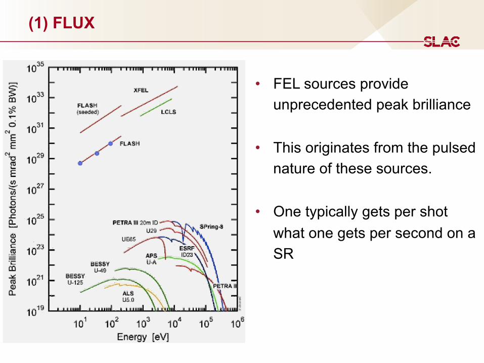
(1) FLUX
• FEL sources provide unprecedented peak brilliance
• This originates from the pulsed nature of these sources.
• One typically gets per shot what one gets per second on a SR

(2) COLLIMATION
Storage Ring FEL
Typ. beam size @40-50m 2-3 x0.5-1mm (h,v)
Typ. divergence high-β30 x 15μrad (h,v)
(example : Troika ID10A at the ESRF)
Typ. beam size @200-400m 0.5-1 x0.5-1mm (h,v)
Typ. Divergence1-2 x 1-2μrad (h,v)
OPERATIONAL PERFORMANCE OF LCLS BEAM INSTRUMENTATION∗
H. Loos† , R. Akre, A. Brachmann, R. Coffee, F.-J. Decker, Y. Ding, D. Dowell, S. Edstrom,P. Emma, A. Fisher, J. Frisch, S. Gilevich, G. Hays, Ph. Hering, Z. Huang, R. Iverson,
M. Messerschmidt, A. Miahnahri, S. Moeller, H.-D. Nuhn, D. Ratner, J. Rzepiela, T. Smith,P. Stefan, H. Tompkins, J. Turner, J. Welch, W. White, J. Wu, G. Yocky,
SLAC, Menlo Park, CA 94025, USA, R. Bionta, LLNL, Livermore, CA 94550, USA
AbstractThe Linac Coherent Light Source (LCLS) X-ray FEL
utilizing the last km of the SLAC linac has been opera-tional since April 2009 and finished its first successful userrun last December. The various diagnostics for electronbeam properties including beam position monitors, wirescanners, beam profile monitors, and bunch length diagnos-tics are presented as well as diagnostics for the x-ray beam.The low emittance and ultra-short electron beam requiredfor X-ray FEL operation has implications on the transverseand longitudinal diagnostics. The coherence effects of thebeam profile monitors and the challenges of measuring fslong bunches are discussed.
INTRODUCTIONThe LCLS facility at the SLAC National Accelerator
Laboratory [1] is the first free electron laser operating atAngstrom wavelengths. Since 2006 the last 1 km of theSLAC linac has been upgraded to serve as the electronbeam source for the FEL and new construction has beenadded to house the undulator and the X-ray facilities. Thefirst x-ray operation was achieved in April 2009 [2] anda subsequent user run utilized the soft X-ray beam. Aftercommissioning of the hard X-ray beam transport the sec-ond user run later in 2010 will take advantage of the fullLCLS capabilities.
Table 1: LCLS accelerator and FEL parametersDesign Meas. Unit
Repetition rate 120 30 HzFinal energy 13.6 13.6 GeVCharge 1 0.25 nCBunch length 20 8-10 µmPeak current 3 3 kAEmittance (injector) 1.2 0.5-1.2 µmSlice emittance (inj.) 1.2 0.4 µmEmittance (linac end) 1.5 0.5-1.2 µm
X-ray wavelength 1.5 1.5 AX-ray pulse energy 1.5 1.5-3.0 mJPhotons per pulse 2.0 1.0-2.3 1012
The ultra-high brightness electron beam necessary for∗Work supported by US DOE contract DE-AC02-76SF00515.† [email protected]
the operation of an X-ray FEL requires the accurate mea-surement of a sub-µm emittance and sub 10 µm long elec-tron beam in both transverse and longitudinal coordinateswith state of the art diagnostics. The layout of the LCLSis depicted in Fig. 1 with the location of some of the di-agnostics devices indicated. The 250 pC electron beam isgenerated in a laser-driven photocathode RF gun at 6 MeVand subsequently accelerated in four linac sections (L0-L3)to energies of 135 MeV, 250 MeV, 4.3 GeV, and the finalenergy of 13.6 GeV. After L1 and L2 the bunches are com-pressed in two chicanes from 750µm to 40µm and 10µm.The beam is then transported through a dog-leg bend mag-net system to the 100 m long undulator consisting of 33segments and dumped in the main beam dump, whereas thegenerated X-ray beam enters the X-ray diagnostics, trans-port, and the various experimental areas (not shown). Themain parameters of the electron and X-ray beam are listedin Table 1. The design parameters refer to the high chargemode at 1 nC, whereas the measured ones are given for themedium charge operating mode at 250 nC. Recently, a lowcharge mode with only 20 pC has been explored [3]. Thebeam in this mode has a slice emittance of 0.14µm andcan be compressed to an estimated final rms bunch lengthof about 1µm giving the same peak current and FEL peakpower, but a much shorter X-ray pulse.
Table 2: LCLS Accelerator diagnostics devicesType # Nom. res. UnitsStrip Line BPM 144 5 µmRF cavity BPM 36 1 µmBeam current monitor 13 2 %Phase cavity 5 100 fsFaraday cup 2 2 %Wire scanner 17 20 µmYAG screen 7 15 µmOTR screen 13 10 µmBunch length monitor 2 5 %Deflecting cavity 2
A list of all the beam diagnostics devices is given in Ta-ble 2 together with their respective highest resolution re-quirements for each device. In the following sections, thedesign and operational performance of the various diag-nostics for transverse and longitudinal beam parameters, aswell as some of the X-ray diagnostics will be discussed.
MOIANB01 Proceedings of BIW10, Santa Fe, New Mexico, US
Instrumentation34
H. Loos et al.
-4 -3.5 -3 -2.5 -2 -1.5
-1.5
-1
-0.5
0
0.5
x (mm)
y (m
m)
Figure 19: Image from a YAG screen in the direct im-ager showing the FEL pulse and the spontaneous radiationclipped by upstream collimator jaws.
photon energy of 8.3 keV. Additional instrumentation forenergy measurement with a thermo-acoustic sensor will beadded to the quick-change diagnostic chamber in the maindump area. One remaining issue for future diagnostics de-velopment is the absolute measurement of the X-ray pulselength.
REFERENCES[1] J. Arthur, et al., Linac Coherent Light Source (LCLS) con-
ceptual design report, SLAC-R-593, SLAC (2002).
[2] P. Emma, Proceedings of PAC 2009, Vancouver, BC, May2009, p. TH3PBI01 (2009).
[3] Y. Ding, et al., Phys. Rev. Lett. 102 (2009) 254801.
[4] J. Irwin, et al., Phys. Rev. Lett. 88 (1999) 1684.
[5] S. Smith, et al., Proceedings of PAC 2009, Vancouver, BC,May 2009, p. TU3GRC05 (2009).
[6] R. M. Lill, et al., Proceedings of PAC 2007, Albuquerque,NM, June 2007, p. FRPMN111 (2007).
[7] P. Emma, et al., Nucl. Instr. and Meth. A 429 (1999) 407.
[8] P. Emma, et al., Proceedings of PAC 2009, Vancouver, BC,May 2009, p. WE5RFP041 (2009).
[9] H. Loos, et al., Proceedings of FEL 2008, Gyeongju, Korea,Aug. 2008, p. THBAU01 (2008).
[10] O. H. Altenmueller, R. R. Larsen, G. A. Loew, Rev. Sci.Instrum. 35 (1964) 438.
[11] R. Akre, et al., Phys. Rev. ST Accel. Beams 11 (2008)030703.
[12] H. Loos, et al., Proceedings of PAC 2007, Albuquerque,NM, June 2007, p. FRPMS071 (2007).
[13] R.A. Bosch, Rev. Sci. Instrum. 73 (2002) 1423.
[14] J. Wu, et al., Proceedings of FEL 2008, Gyeongju, Korea,Aug. 2008, p. MOPPH052 (2008).
[15] S. P. Hau-Riege, et al., J. Appl. Phys. 103 (2008) 053306.
Proceedings of BIW10, Santa Fe, New Mexico, US MOIANB01
Instrumentation43
It can have a huge impact on X-ray optics (e.g. focusing)

(3) POSITION
Storage Ring FEL
Rock Stable !
XPP Instrument120Hz
Beam fluctuates in position ( >10% of its size)

(4) INTENSITY
Storage Ring FEL
Rock Stable !
With Or
Without Top-up
PINK
Si(111)
Drastic difference between pink and mono beam
Courtesy of XPP

(4) INTENSITY
Storage Ring
Rock Stable !
With Or
Without Top-up
Intrinsic intensity fluctuation coming from the SASE process itself, in addition of machine instability and special behavior in monochromatic beam
Si(111)
FEL

Storage Ring FEL : LCLSPulse duration : typ. 50-100psHigh repetition rate (100sMHz)
Pulse duration : typ. < 100fsRepetition rate ~50-100Hz
~10ps~ns
~1-100fs~ms
~mJ~nJ
Time Structure
Time Structure
(5) PULSE DURATION & (6) TIMING
Step position indicates
arrival time
Tunable

(7) E-spectrum
Storage Ring FELAccess to high Energies with 3rd harmonicStable and well define energy spectrum1st harmonic width : 1-4%
(example : Troika ID10A at the ESRF)
Access to high Energies with 3rd harmonic1st harmonic width : 0.1-0.2% (<dE/E>=0.7%)
Fluctuating spectrum : e-beam jitter and structure
7
FEL self seeding
Intense x-ray source with spiky spectrum
Monochromator filter creates seed with controlled spectrum
FEL amplifier (exponential intensity gain)
Additional amplification (linear gain)
seeded
SASE
Photon energy
Inte
nsity
“seeding” will fix this

(8) Degree of Coherence
Storage Ring FELLimited degree of Coherence
Slit down the beam to typ. 20x20 micron beams to extract the coherent
fraction of the beam.
xt ! ð1=2Þðl=DYÞ ¼ ðl=2ÞðR=SÞ ð3Þ
Typical transverse coherence lengths at third generation sources range between
10 and 100 mm for l = 1 A and a distance R ! 50 m from the source. The
spatial coherence properties of a synchrotron X-ray beam can be monitored by
Fraunhofer diffraction from a collimating aperture. > Figure 18-2 shows Airy
fringes from a 5 % 5 mm2 slit located 46 m from the ID10A undulator source at
ESRF. Circular pinhole apertures produce Fraunhofer diffraction patterns where
the central maximum has an angular width that depends upon the pinhole size d
and is typically of order l/d [55, 56].
The temporal coherence of the beam can be described by the longitudinal
coherence time t0 which defines a longitudinal coherence length xl = ct0 over
which the phase of the field amplitude undergoes no fluctuations. t0 is a measure
of the monochromaticity of the beam and is related to the bandwidth Dn of the
light by
t0 ¼ 1=Dn ð4Þ
Awell monochromatized X-ray beam has a bandwidth of Dl/l = 10& 4 and hence
a longitudinal coherence time t0 ! 10& 15 s. The longitudinal coherence length
is given by
. Figure 18-2Airy fringes from a 5 % 5 mm2 slit, recorded with l = 1.54 A radiation at 1.5 m from the slit.The visibility V of the fringes can be quantified by V = (Imax& Imin)/(Imax + Imin), where Imax is afringe maximum and Imin is an adjacent minimum
X-Ray Photon Correlation Spectroscopy (XPCS) 18 957
Grübel, Madsen, Robert ,XPCS , Springer (2008) A. Robert et al., J. Phys : Conf. Ser. 425, 212009 (2012)
The beam is fully transversely coherent

Day to day operation
Something very different from SR sources , we have :
“ BAD” days and “GOOD” days
• a little less than 1mJ • Very large intensity fluctuations
• more than 1.5mJ up to 5 mJ• 10-15% intensity fluctuation and no
loss at all

28
3) FEL Experimental Strategies
1) Free Electron Lasers 1) What is an FEL ?2) Status of FEL’s worldwide vs Storage Rings
2) FELs vs. Synchrotron Sources:1) Understand the Peak Brilliance graphs2) LCLS3) In depth comparison from the experimentalist point of view
3) Experimental Strategies to BEST use FELs
4) What’s coming next ?

29
3.1 ) Normalizing, Filtering, Binning
•Each X-ray Pulse is UNIQUE•Each X-ray pulse fluctuates in many ways
•Necessity to characterize with precision every pulse to the extent possible•Diagnostics are critical • Filtering
• Normalizing• Binning• Averaging

30
3.2 ) Diffract before destroy (c.f. Diling Zhu)
Let’s correct a misconception !Most samples survive a single shot FEL beam
If all photons are focused in a very small spot size( <2-5 micron) nothing survive a single shot
Neutze et al., Nature 406, pp752 (2000)
“Diffract-Before-Destroy” take advantage of the peak power to obtain information before the systems reacts to the X-ray probe

31
3.4 ) Sample Delivery to support “Diffract and Destroy”
Ability to change the sample when damage by the FEL
https://www6.slac.stanford.edu/news/2015-02-02-5-ways-put-tiny-targets-front-x-ray-laser.aspx
Drop-on-Demand
Virtual Nozzle Jet
Aerosol JetSimple Liquid Jet
Rastering
LIQUIDS
SOLIDS
Optimized for each sample

32
3.3 ) typ. Pump- Probe Experiment (c.f. Diling Zhu)
DetectorsSample
Δt
ProbePump
Δt
Pump-Probe : evolution of relative signal with X-ray probe at different time delays
Δt after excitation (probe)• Reproducibility of the excited state
• Reproducibility of the sample if damaged
• Ability to synchronize two short pulses
• Correct for timing jitter
Courtesy XPP (Zhu et al.)
Δt

33
4) What is coming next : LCLS-II and LCLS-II-HE
1) Free Electron Lasers 1) What is an FEL ?2) Status of FEL’s worldwide vs Storage Rings
2) FELs vs. Synchrotron Sources:1) Understand the Peak Brilliance graphs2) LCLS3) In depth comparison from the experimentalist point of view
3) Experimental Strategies to BEST use FELs
4) What’s coming next ?
34
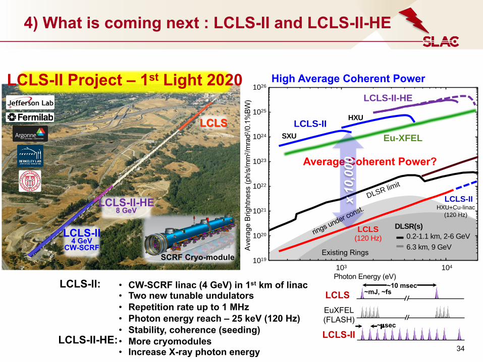
4) What is coming next : LCLS-II and LCLS-II-HE
• CW-SCRF linac (4 GeV) in 1st km of linac• Two new tunable undulators• Repetition rate up to 1 MHz• Photon energy reach – 25 keV (120 Hz)• Stability, coherence (seeding)• More cryomodules• Increase X-ray photon energy
LCLS-II:LCLS
~10 msec~mJ, ~fs
~µsec
LCLS-II
EuXFEL(FLASH)
High Average Coherent Power
Average Coherent Power?
LCLS
LCLS-II4 GeV
CW-SCRFSCRF Cryo-module
LCLS-II Project – 1st Light 2020
Existing Rings
rings under const.
Photon Energy (eV)
Aver
age
Brig
htne
ss (p
h/s/
mm
2 /mra
d2/0
.1%
BW)
LCLS-II
LCLS-II-HE
Eu-XFEL
LCLS (120 Hz)
DLSR(s)0.2-1.1 km, 2-6 GeV6.3 km, 9 GeV
SXU
HXU
LCLS-IIHXU+Cu-linac
(120 Hz)
1041031019
1020
1021
1022
1023
1024
1025
1026
x 10
,000
DLSR limit
LCLS-II-HE8 GeV
LCLS-II-HE:

Free Electron Lasers : using X-rays for Science
SAXS
Diff
XPCS
CXDIXES
XAS
EXAFS
XANES
…
PUMP
• Relying on the long experience of
synchrotron Storage Ring sources
• Experiments use at least one of the FEL beam properties
• Ideal for ultrafast dynamics, radiation
sensitive samples, pump-probe (optical, THz,
Field, etc.)
• Some experiments use more than one technique simultaneously or sequentially
• Experimental descriptions by Diling Zhu (next)
Materials Science Chemistry
Atomic & Molecular Dynamics
High Energy Density Life Sciences
“Linac Coherent Light Source: the first five years”, Rev. Mod. Phys. 88, 015007 (2016)