physics of free-electron lasers introductionuspas.fnal.gov/materials/14unm/1_introduction.pdfphysics...
TRANSCRIPT
LA-UR 14-23580
Physics of Free-Electron Lasers
Introduction
Dinh C. Nguyen & Quinn R. Marksteiner
Los Alamos National Laboratory
US Particle Accelerator School
June 23 – 27, 2014
LA-UR 14-23580
I. Introduction
II. One-dimensional FEL Theory
III. Optical Architectures
IV. FEL Seeding Techniques
V. Self-Amplified Spontaneous Emission
VI. FEL Harmonic Generation
2
LA-UR 14-23580
1. Laser, Light Sources & Gaussian Beams
2. Electron Motion in an Undulator
3. Undulator Radiation
4. FEL Basics
5. Pendulum Equation
6. Radiation from Ensembles of Electrons
7. Fourth Generation Light Sources
3

LA-UR 14-23580
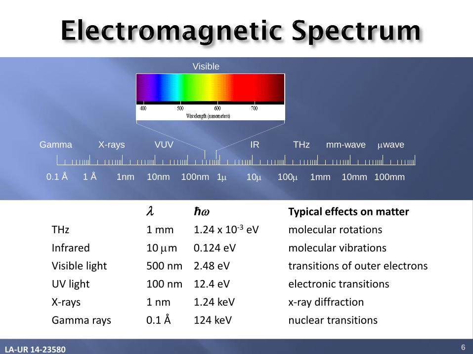
Photon energy scales proportionally with frequency and inversely with wavelength (the shorter the wavelength, the higher the energy).
4
hchfW
nmmeVW
240,124.1
LA-UR 14-23580 5
B
E
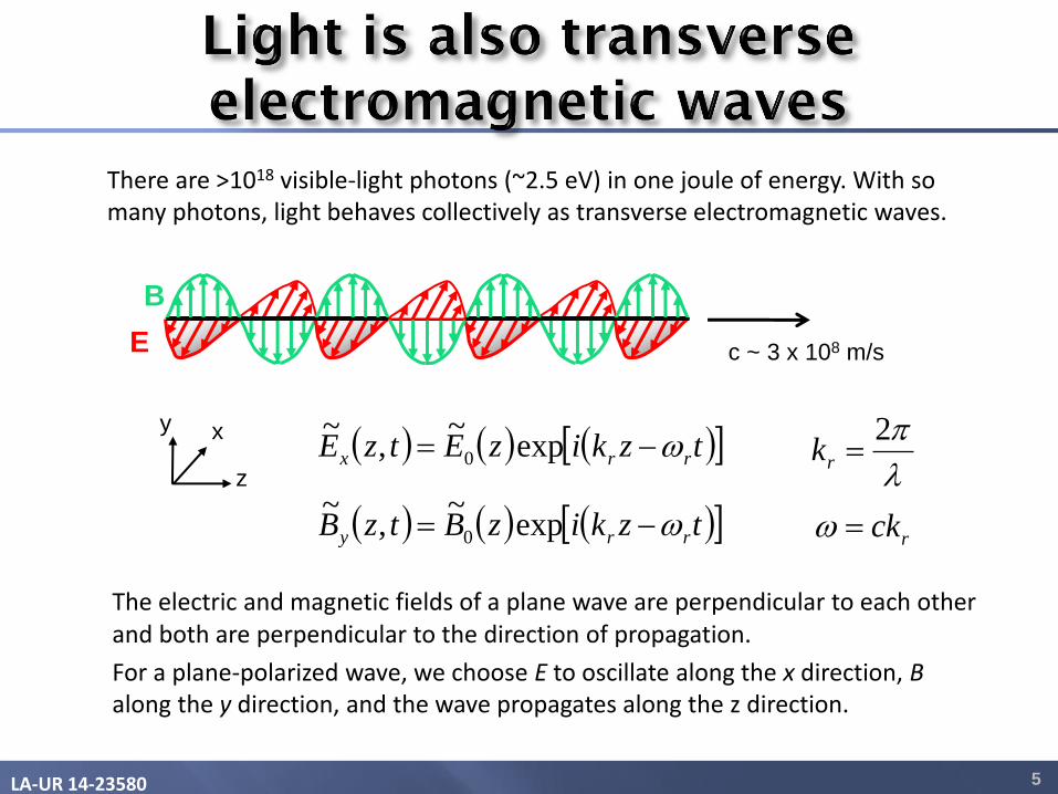
There are >1018 visible-light photons (~2.5 eV) in one joule of energy. With so many photons, light behaves collectively as transverse electromagnetic waves.
The electric and magnetic fields of a plane wave are perpendicular to each other and both are perpendicular to the direction of propagation.
For a plane-polarized wave, we choose E to oscillate along the x direction, B along the y direction, and the wave propagates along the z direction.
c ~ 3 x 10⁸ m/s
y x
z
tzkizEtzE rrx exp~
,~
0
tzkizBtzB rry exp~
,~
0
2rk
rck
LA-UR 14-23580 6
ħ Typical effects on matter
THz 1 mm 1.24 x 10⁻³ eV molecular rotations
Infrared 10 m 0.124 eV molecular vibrations
Visible light 500 nm 2.48 eV transitions of outer electrons
UV light 100 nm 12.4 eV electronic transitions
X-rays 1 nm 1.24 keV x-ray diffraction
Gamma rays 0.1 Å 124 keV nuclear transitions
1 Å 1nm 10nm 100nm 1 10 100 1mm 10mm 100mm
Gamma X-rays VUV IR THz mm-wave wave
Visible
0.1 Å
LA-UR 14-23580 7
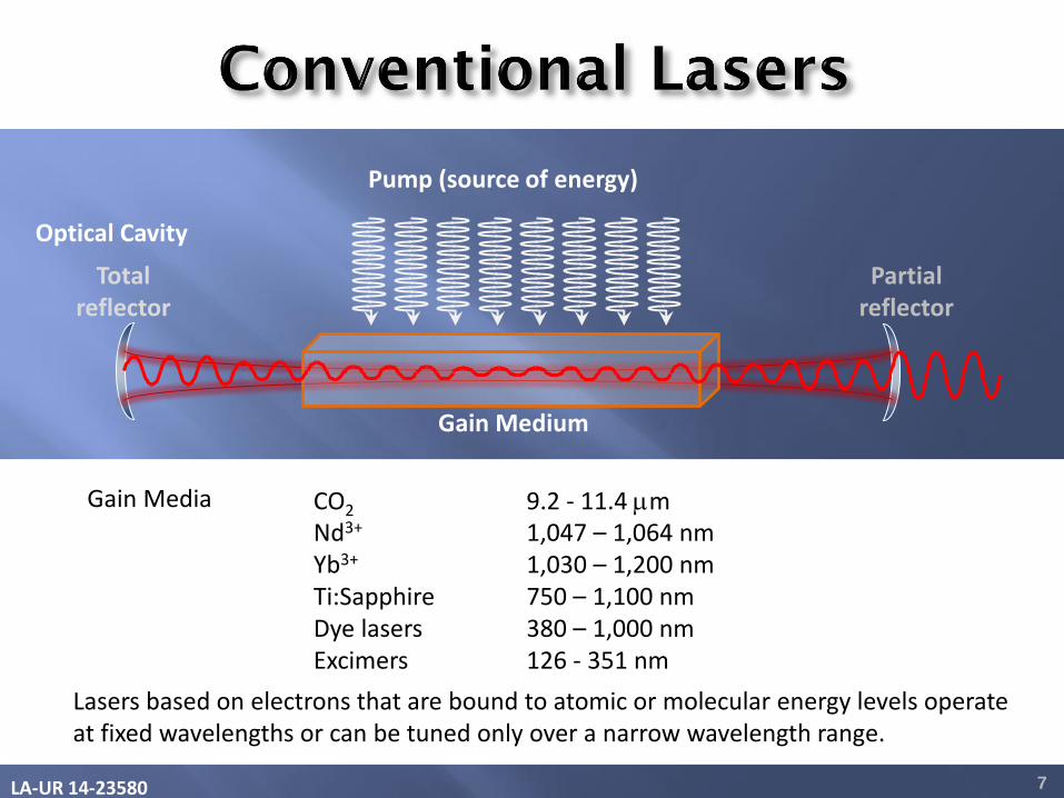
Partial reflector
Total reflector
Pump (source of energy)
Gain Medium
Optical Cavity
Gain Media CO2 9.2 - 11.4 m
Nd3+ 1,047 – 1,064 nm Yb3+ 1,030 – 1,200 nm Ti:Sapphire 750 – 1,100 nm Dye lasers 380 – 1,000 nm Excimers 126 - 351 nm Lasers based on electrons that are bound to atomic or molecular energy levels operate
at fixed wavelengths or can be tuned only over a narrow wavelength range.
LA-UR 14-23580 8
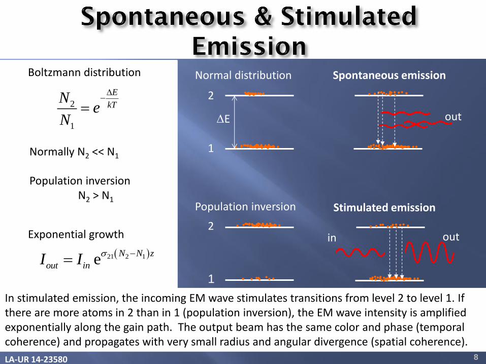
In stimulated emission, the incoming EM wave stimulates transitions from level 2 to level 1. If there are more atoms in 2 than in 1 (population inversion), the EM wave intensity is amplified exponentially along the gain path. The output beam has the same color and phase (temporal coherence) and propagates with very small radius and angular divergence (spatial coherence).
Boltzmann distribution
2
1
E
kTN
eN
21 2 1eN N z
out inI I
Exponential growth
Stimulated emission Population inversion
Normal distribution
E
Spontaneous emission
in out
1
2
1
2
out
Normally N2 << N1
Population inversion N2 > N1
LA-UR 14-23580
2
cL
9
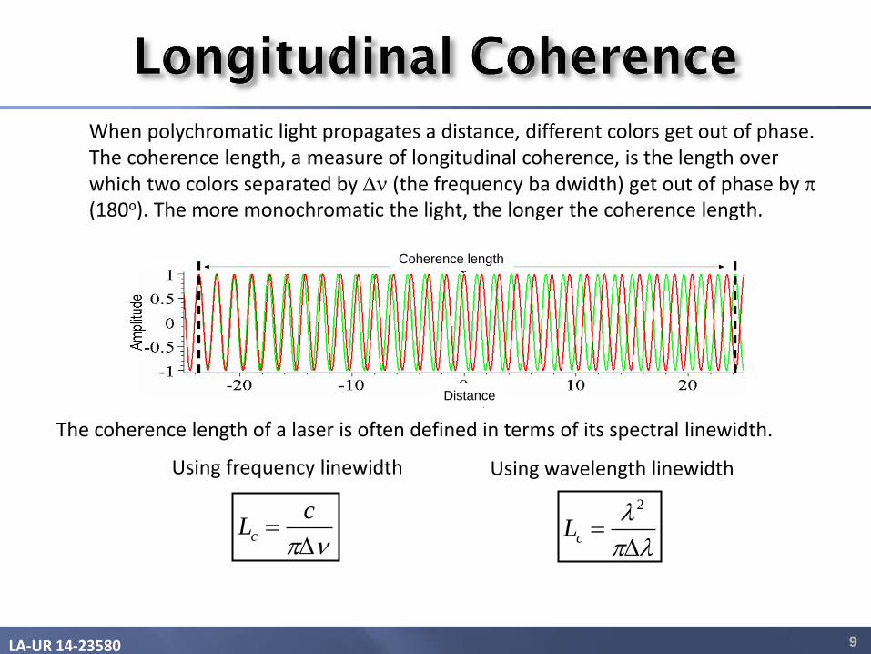
When polychromatic light propagates a distance, different colors get out of phase. The coherence length, a measure of longitudinal coherence, is the length over which two colors separated by n (the frequency ba dwidth) get out of phase by (180o). The more monochromatic the light, the longer the coherence length.
The coherence length of a laser is often defined in terms of its spectral linewidth.
Using frequency linewidth Using wavelength linewidth
c
cL
n
Coherence length
Distance
LA-UR 14-23580 10
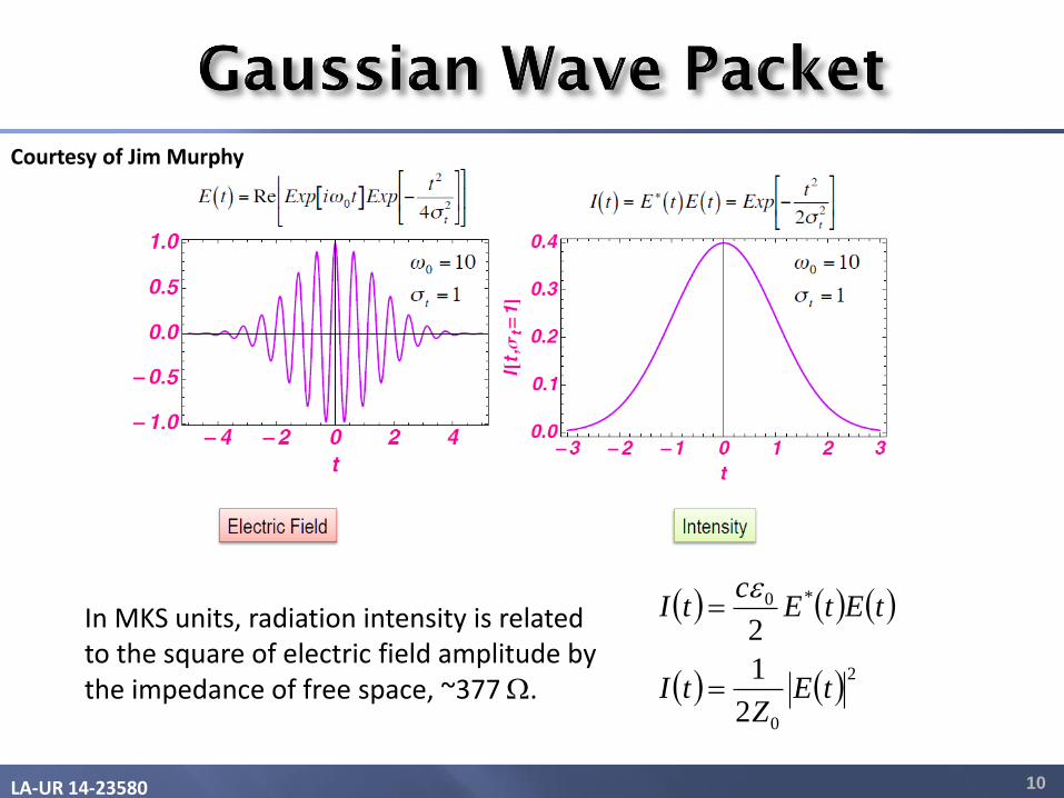
In MKS units, radiation intensity is related to the square of electric field amplitude by the impedance of free space, ~377 W.
2
0
*0
2
1
2
tEZ
tI
tEtEc
tI
Courtesy of Jim Murphy
LA-UR 14-23580 11
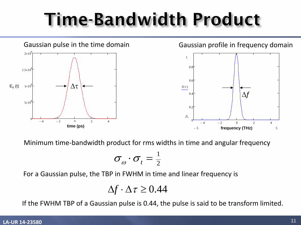
For a Gaussian pulse, the TBP in FWHM in time and linear frequency is
4 2 0 2 40
5 108
1 109
1.5 109
2 109
g t( )
ttime (ps)
E0 (t) t Fourier transform
4 2 0 2 40
0.2
0.4
0.6
0.8
1
0
f n( )
55 nfrequency (THz)
f
Gaussian pulse in the time domain Gaussian profile in frequency domain
If the FWHM TBP of a Gaussian pulse is 0.44, the pulse is said to be transform limited.
44.0 tf
Minimum time-bandwidth product for rms widths in time and angular frequency
2
1 t
LA-UR 14-23580 12
-4.0 -3.0 -2.0 -1.0 0.0 1.0 2.0 3.0 4.0
w
x
Intensity
.135 I0
I0
2 3 4 4 3 2
FWHM .5 I0
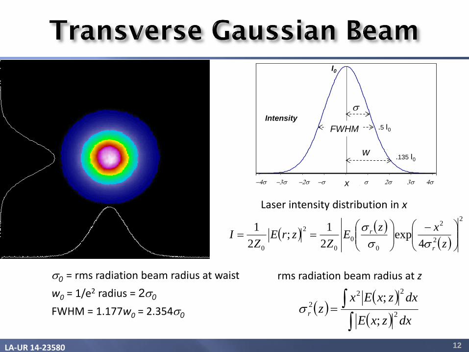
0 = rms radiation beam radius at waist
w0 = 1/e2 radius = 20
FWHM = 1.177w0 = 2.3540
dxzxE
dxzxExzr 2
22
2
;
;
2
2
2
0
0
0
2
0 4exp
2
1;
2
1
z
xzE
ZzrE
ZI
r
r
Laser intensity distribution in x
rms radiation beam radius at z

LA-UR 14-23580 13
Gaussian beams are transverse EM modes. The lowest Gaussian mode is TEM00.
22 2
0 21
R
zw w
z
The product of rms radius and angular divergence is equal to the photon beam emittance. The smaller the beam radius at the waist, the larger the divergence angle. Rayleigh length is the length over which the beam area doubles.
4' rr
2
0wzR
0w
LA-UR 14-23580
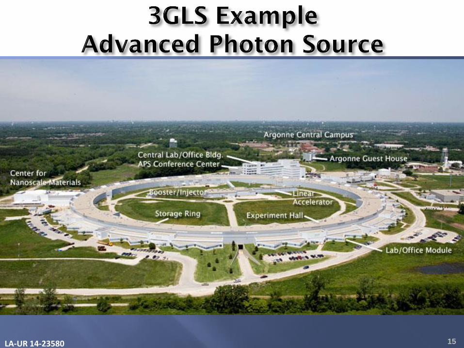
Storage-ring-based 3rd Generation Light Sources are the tools of discovery for
• Life Science (e.g., structures of biological macromolecules)
• Chemistry (e.g., detecting chemical species at surfaces)
• Materials Science (e.g., phase contrast imaging)
• Condensed Matter Physics (e.g., studying warm dense matter)
See XDL-2011 “Workshop on Science at the Hard X-ray Diffraction Limit”
3rd Generation Light Sources are electron storage-ring facilities producing synchrotron radiation. Synchrotron radiation can be generated in undulators (alternating dipoles with K < 1), wigglers (K>>1) or single dipole magnets.
The brightness of 3GLS is 1023 – 1025 x-ray photons/(s-mm2 -mrad2-0.1% BW). In a 3GLS, emittance in x is set by the balance between radiation damping and quantum excitation due to the random nature of photon emission. Emittance in y is a few % of x emittance, caused by residual coupling between x and y motions.
14
LA-UR 14-23580 15
LA-UR 14-23580 16
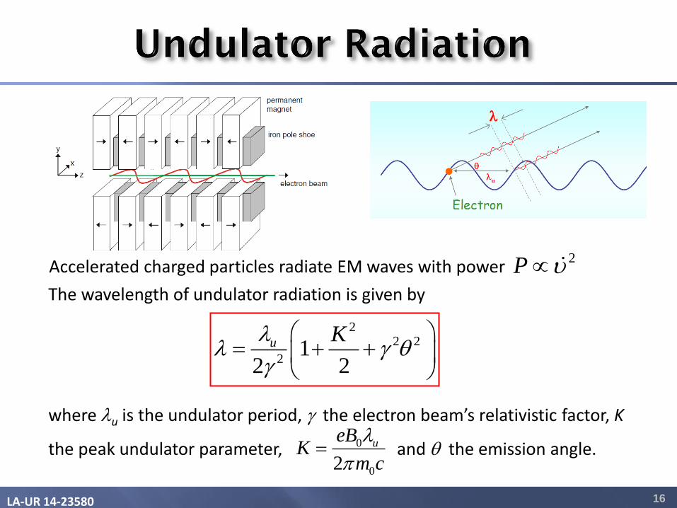
The wavelength of undulator radiation is given by
where u is the undulator period, g the electron beam’s relativistic factor, K
the peak undulator parameter, and the emission angle.
22 2
21
2 2
u K g
g
0
02
ueBK
m c
Accelerated charged particles radiate EM waves with power
2P
LA-UR 14-23580 17
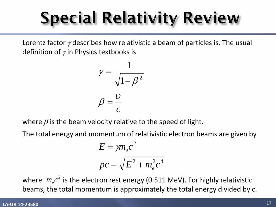
The total energy and momentum of relativistic electron beams are given by where is the electron rest energy (0.511 MeV). For highly relativistic beams, the total momentum is approximately the total energy divided by c.
422
2
cmEpc
cmE
e
e
g
Lorentz factor g describes how relativistic a beam of particles is. The usual definition of g in Physics textbooks is
c
g
21
1
where is the beam velocity relative to the speed of light.
2cme
LA-UR 14-23580 18
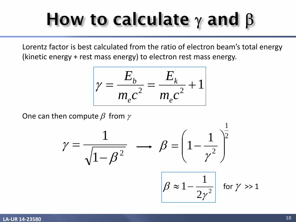
Lorentz factor is best calculated from the ratio of electron beam’s total energy (kinetic energy + rest mass energy) to electron rest mass energy.
One can then compute from g
122
cm
E
cm
E
e
k
e
bg
21
1
g
2
1
2
11
g
for g >> 1 22
11
g
LA-UR 14-23580 19
zez
yey
xex
mp
mp
mp
g
g
g
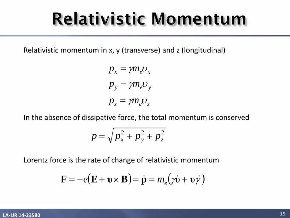
Relativistic momentum in x, y (transverse) and z (longitudinal)
In the absence of dissipative force, the total momentum is conserved
222
zyx pppp
Lorentz force is the rate of change of relativistic momentum
gg υυpBυEF eme

LA-UR 14-23580 20
Transverse dimensions (x and y) are unchanged.
The length of a moving object along direction of motion is contracted by g. The proper length L* is measured in the object’s rest frame.
The time interval t* between two events in the moving frame appears longer by g as observed in the frame at rest.
x
y
z
y’
x’
z’
c Beam frame Lab
frame
*
*
tt
LL z
z
g
g
In this diagram, the “Beam frame” is moving at speed vz = c with respect to the Lab frame.

LA-UR 14-23580 21
zkykBB
zkykBB
B
uuz
uuy
x
cossinh
sincosh
0
0
0
Consider the magnetic field components of an undulator with period u
For the case where the electron beam is small and confined to the y = 0 plane, the magnetic field can be written as a sinusoidal function of z only.
yB ˆsin0 zkB u
where the undulator wavenumber is defined as
u
uk
2

LA-UR 14-23580 22
Lorentz force due to undulator magnetic field on the electrons
Coupled differential equations
Bυυ emeg
yz
e
x Bm
ex
g zx
e
z Bm
ez
g
Use the approximation that vz is constant and equal to c
zkcBm
e
dt
du
e
x sin0g
zkBm
e
dz
du
e
x sin0g
ctz
The approximation vz ~ c is valid since vx << vz
LA-UR 14-23580 23
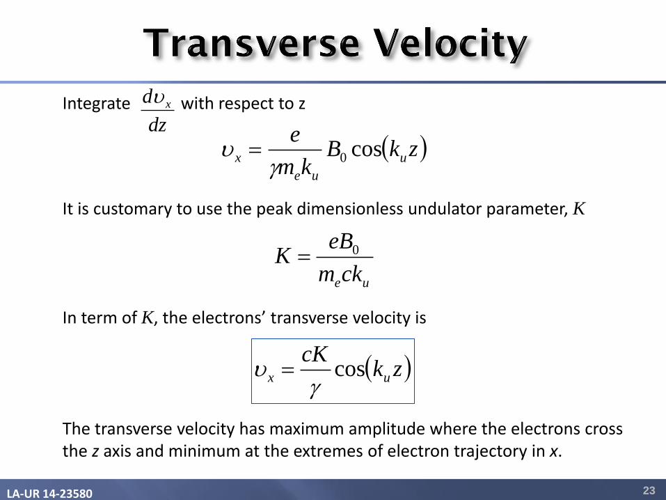
Integrate with respect to z
It is customary to use the peak dimensionless undulator parameter, K
ueckm
eBK 0
In term of K, the electrons’ transverse velocity is The transverse velocity has maximum amplitude where the electrons cross the z axis and minimum at the extremes of electron trajectory in x.
zkBkm
eu
ue
x cos0g
zkcK
ux cosg
dz
d x

LA-UR 14-23580 24
vz
The transverse velocity is derived from the total velocity at the expense of the axial velocity.
y
x
z
The axial velocity is modulated at twice the spatial frequency of the undulator motion. The axial speed is maximum at the edges of the electrons’ orbit and minimum where the electrons cross the axis.
vx v
zkKK
c
zkKc
zkK
c
uz
uz
uz
2cos22
12
11
2
2cos111
cos1
1
22
2
2/12
2
2/1
2
2
2
g
gg
gg
222
xz c

LA-UR 14-23580 25
2
2
11 1
2 2z
Kc
g
Average axial velocity
z
Motion in beam’s frame
Axial velocity with 2 ku modulations
zkK
uzz 2cos2
2
In the frame traveling at average vz, the electrons execute figure 8 motion on the x-z plane. The figure 8 motion mixing with the undulator motion gives rise to harmonic radiation.
y
x
z
LA-UR 14-23580 26
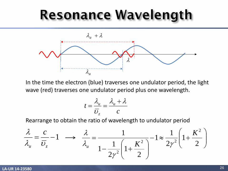
In the time the electron (blue) traverses one undulator period, the light wave (red) traverses one undulator period plus one wavelength. Rearrange to obtain the ratio of wavelength to undulator period
ct u
z
u
1zu
c
2
12
11
21
2
11
1 2
22
2
K
Ku g
g
u
u

LA-UR 14-23580 27
Lab frame u
Beam frame u
y’
x’
z’
x
y
z
In the beam frame, the undulator period is contracted by g*
The reduced g* is given by *g
u
u
21
1
1
22
*
Kz
g
g

LA-UR 14-23580 28
y’
x’
z’
Beam frame The Lorentz transformed undulator field acts like a traveling electromagnetic wave causing the electron to oscillate in the x’ direction.
B’
E’
Real photons are radiated by the electron in a dipole radiation pattern at the same wavelength as the incident electromagnetic wave.
View from the top
In Inverse Compton Scattering, a laser beam is used in place of a magnetostatic undulator. The laser wavelength in the beam frame is modified by the Doppler shift, which depends on the angle between the laser and electron beams.
g
cos1* L
L
LA-UR 14-23580 29
x
y
z
Beam frame
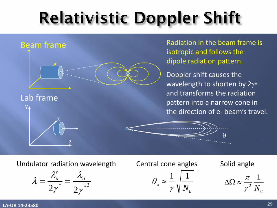
Doppler shift causes the wavelength to shorten by 2g* and transforms the radiation pattern into a narrow cone in the direction of e- beam’s travel.
Lab frame
2**22 g
g
uu
Undulator radiation wavelength
u
xN
11
g
Central cone angles
uN
12g
W
Solid angle
Radiation in the beam frame is isotropic and follows the dipole radiation pattern.
LA-UR 14-23580 30
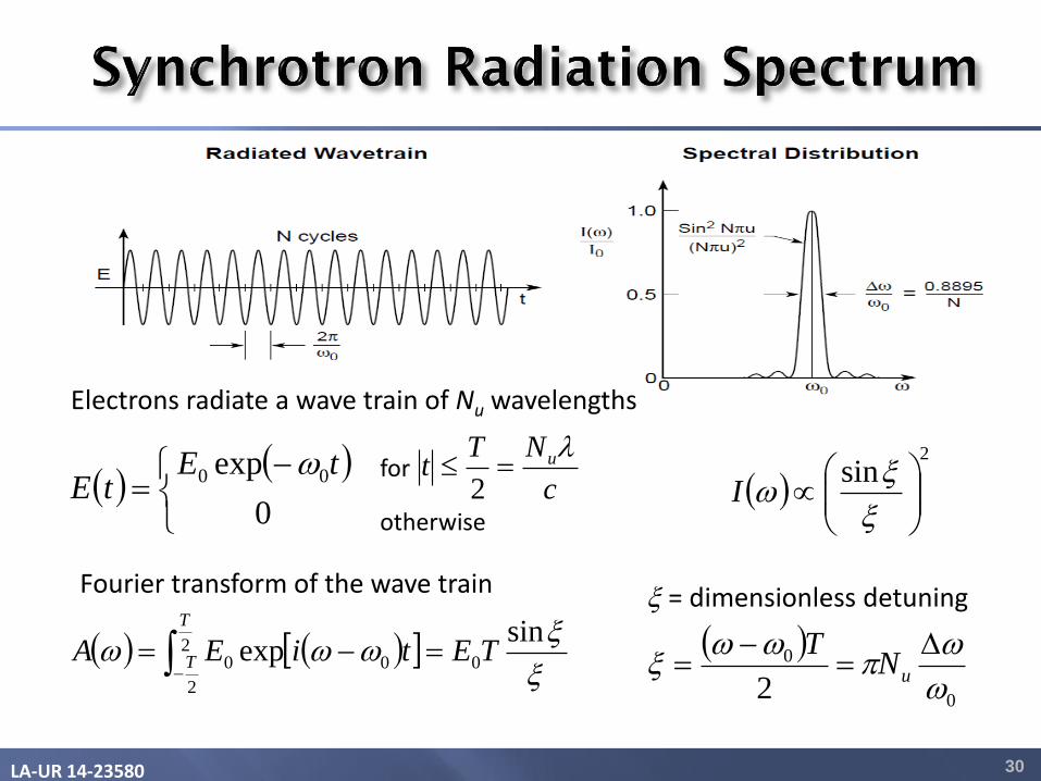
Electrons radiate a wave train of Nu wavelengths
0
exp 00 tEtE
c
NTt u
2for
otherwise
sinexp 0
2
2
00 TEtiEAT
T
Fourier transform of the wave train
0
0
2
uN
T
2
sin
I
= dimensionless detuning
LA-UR 14-23580 31
22
2
2
0
42
21
3
W K
Kce
d
dP
u
g
uu
spontNK
KceP
1
21
32
2
2
2
0
22
g
22
2
0
2
21
K
KIeP
u
spont
g
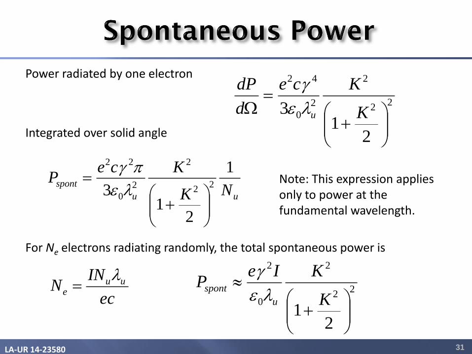
Power radiated by one electron
For Ne electrons radiating randomly, the total spontaneous power is
ec
INN uu
e
Integrated over solid angle
Note: This expression applies only to power at the fundamental wavelength.
LA-UR 14-23580 32
21
4 2
2
0
2
K
KN
c
eN espont
21
2
2
K
KNN espont
22
2
0
2
21
K
KIeP
u
spont
g
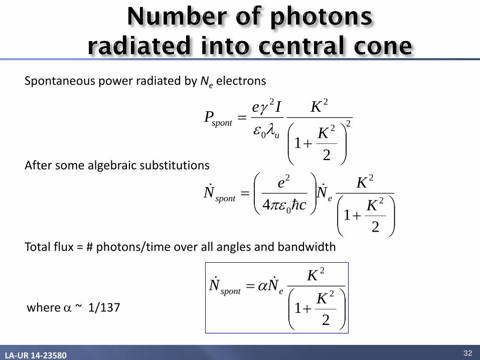
Spontaneous power radiated by Ne electrons
After some algebraic substitutions
Total flux = # photons/time over all angles and bandwidth
where ~ 1/137

LA-UR 14-23580 33
Relative bandwidth, emission angle, and solid angle of the central cone
22
2
2 21
2
1g
g
K
m
um
u
mmN
122g
W
um mN
1
Harmonics are produced in planar undulators, not in helical undulators. Odd harmonics occur on axis. Even harmonics occur off axis. Harmonic wavelength
umNg
1
Spectra over all angles and through an aperture
LA-UR 14-23580
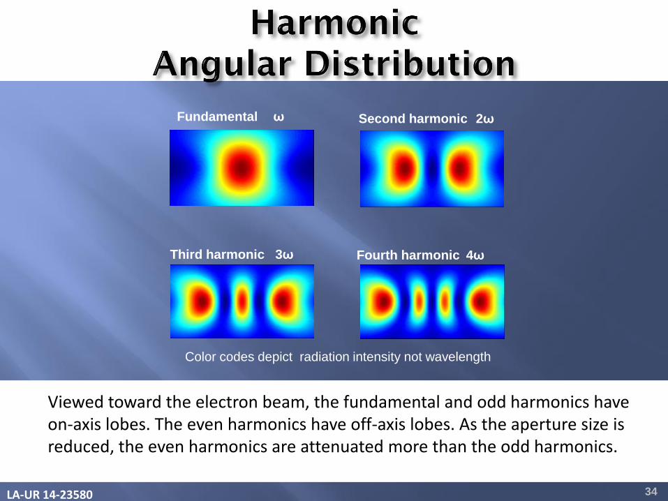
Fundamental ω Second harmonic 2ω
Third harmonic 3ω Fourth harmonic 4ω
Color codes depict radiation intensity not wavelength
Viewed toward the electron beam, the fundamental and odd harmonics have on-axis lobes. The even harmonics have off-axis lobes. As the aperture size is reduced, the even harmonics are attenuated more than the odd harmonics.
34
LA-UR 14-23580 35
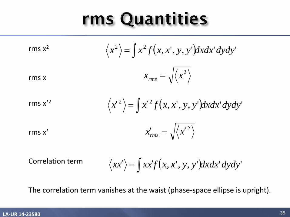
rms x2
rms x
rms x’2
rms x’ Correlation term The correlation term vanishes at the waist (phase-space ellipse is upright).
''',,',22 dydydxdxyyxxfxx
''',,',22 dydydxdxyyxxfxx
2xxrms
2xxrms
''',,', dydydxdxyyxxfxxxx

LA-UR 14-23580 36
The electron beam emittance also contributes to the spreading of the
photon beam in phase space. At the beam waist, the x-x’ correlation vanishes and the beam’s rms emittance is simply
'x x x
LA-UR 14-23580
“
37
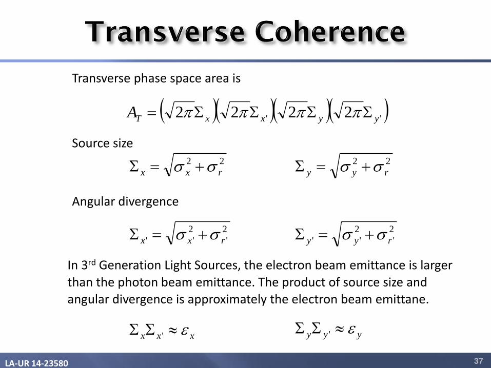
Transverse phase space area is
'' 2222 yyxxTA
22
rxx
Source size 22
ryy
Angular divergence
2
'
2
'' rxx 2
'
2
'' ryy
In 3rd Generation Light Sources, the electron beam emittance is larger
than the photon beam emittance. The product of source size and angular divergence is approximately the electron beam emittane.
xxx ' yyy '
LA-UR 14-23580 38
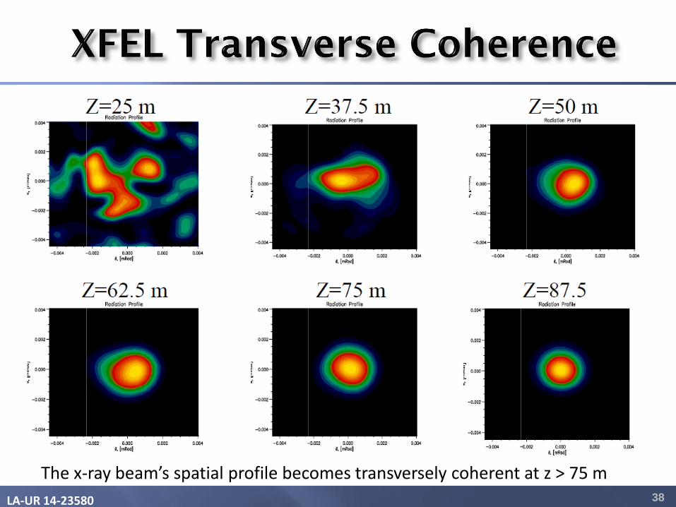
The x-ray beam’s spatial profile becomes transversely coherent at z > 75 m
LA-UR 14-23580 39
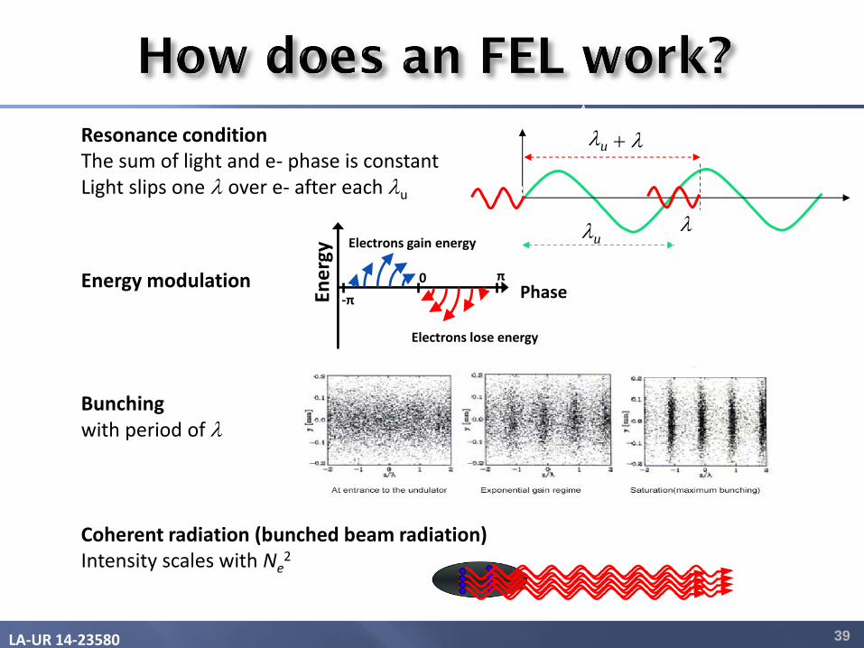
Resonance condition The sum of light and e- phase is constant Light slips one over e- after each u
Bunching with period of
Energy modulation
Coherent radiation (bunched beam radiation) Intensity scales with Ne
2
0 Phase En
erg
y
π
-π
Electrons gain energy
Electrons lose energy
u
u
LA-UR 14-23580
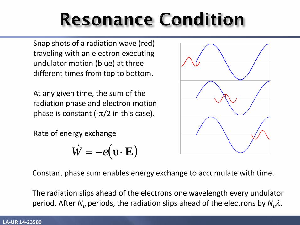
Constant phase sum enables energy exchange to accumulate with time. The radiation slips ahead of the electrons one wavelength every undulator period. After Nu periods, the radiation slips ahead of the electrons by Nu.
Snap shots of a radiation wave (red) traveling with an electron executing undulator motion (blue) at three different times from top to bottom. At any given time, the sum of the radiation phase and electron motion phase is constant (-/2 in this case). Rate of energy exchange
Eυ eW
LA-UR 14-23580 41
0
Phase
Ene
rgy
π
-π
Electrons gain energy
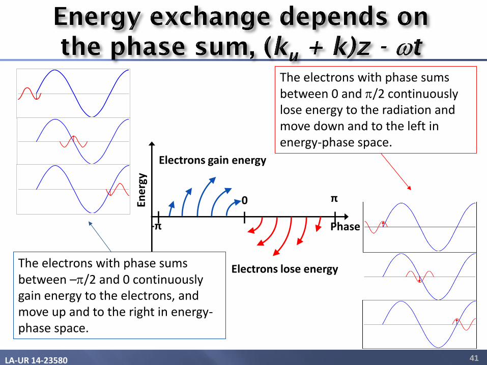
Electrons lose energy The electrons with phase sums between –/2 and 0 continuously gain energy to the electrons, and move up and to the right in energy-phase space.
The electrons with phase sums between 0 and /2 continuously lose energy to the radiation and move down and to the left in energy-phase space.
LA-UR 14-23580 42
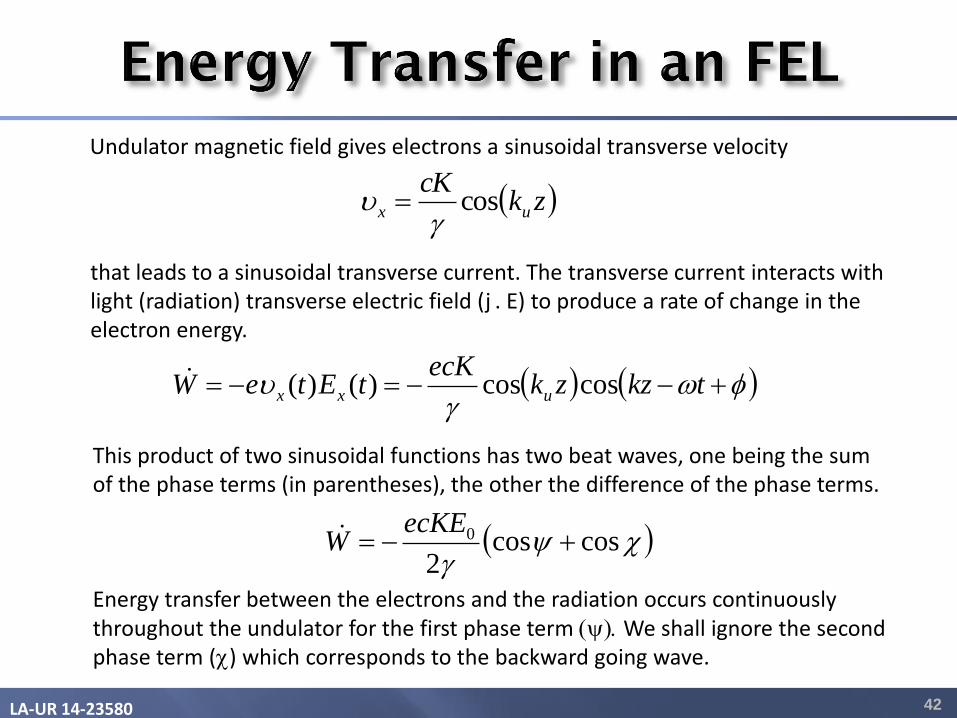
Undulator magnetic field gives electrons a sinusoidal transverse velocity
This product of two sinusoidal functions has two beat waves, one being the sum of the phase terms (in parentheses), the other the difference of the phase terms. Energy transfer between the electrons and the radiation occurs continuously throughout the undulator for the first phase term y. We shall ignore the second phase term (c) which corresponds to the backward going wave.
that leads to a sinusoidal transverse current. The transverse current interacts with light (radiation) transverse electric field (j . E) to produce a rate of change in the electron energy.
zkcK
ux cosg
g
tkzzkecK
tEteW uxx coscos)()(
cyg
coscos2
0 ecKE
W
LA-UR 14-23580 43
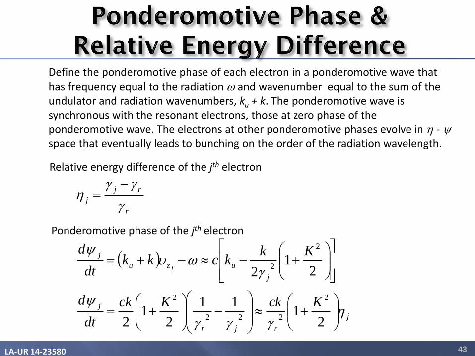
Define the ponderomotive phase of each electron in a ponderomotive wave that has frequency equal to the radiation and wavenumber equal to the sum of the undulator and radiation wavenumbers, ku + k. The ponderomotive wave is synchronous with the resonant electrons, those at zero phase of the ponderomotive wave. The electrons at other ponderomotive phases evolve in h - y
space that eventually leads to bunching on the order of the radiation wavelength.
Relative energy difference of the jth electron
r
rj
jg
ggh
Ponderomotive phase of the jth electron
j
rjr
j
j
uzu
j
KckKck
dt
d
Kkkckk
dt
d
j
hggg
y
g
y
21
11
21
2
21
2
2
222
2
2
2
LA-UR 14-23580 44
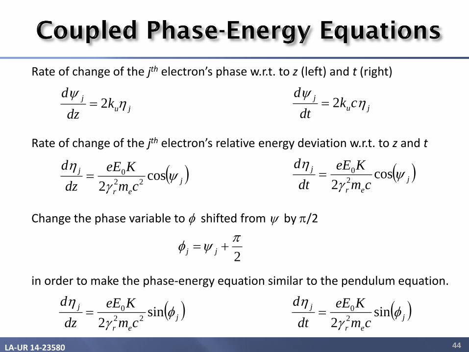
Rate of change of the jth electron’s phase w.r.t. to z (left) and t (right)
Rate of change of the jth electron’s relative energy deviation w.r.t. to z and t
ju
jk
dz
dh
y2
j
er
j
cm
KeE
dz
dy
g
hcos
2 22
0
Change the phase variable to shifted from y by /2 in order to make the phase-energy equation similar to the pendulum equation.
j
er
j
cm
KeE
dz
d
g
hsin
2 22
0
2
y jj
ju
jck
dt
dh
y2
j
er
j
cm
KeE
dt
dy
g
hcos
2 2
0
j
er
j
cm
KeE
dt
d
g
hsin
2 2
0
LA-UR 14-23580 45
sinl
g
0sin l
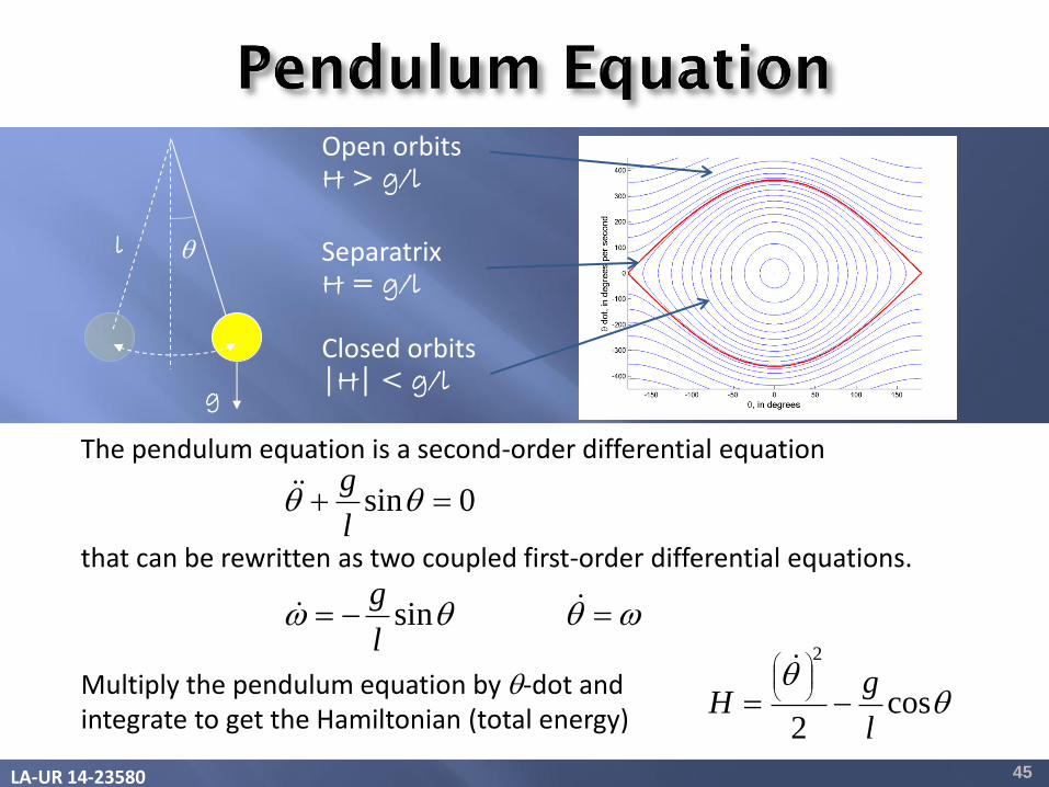
gThe pendulum equation is a second-order differential equation
that can be rewritten as two coupled first-order differential equations.
Open orbits H > g/l
Separatrix H = g/l
Closed orbits |H| < g/l
Multiply the pendulum equation by -dot and integrate to get the Hamiltonian (total energy)
cos2
2
l
gH
l
g
LA-UR 14-23580 46
n
sinv a n
sina
n
n
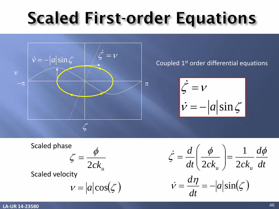
Coupled 1st order differential equations
uck2
dt
d
ckckdt
d
uu
2
1
2
n cosa
Scaled phase
Scaled velocity
h
n sinadt
d
LA-UR 14-23580 47
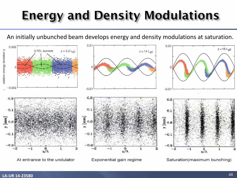
(linear regime)
(nonlinear regime)
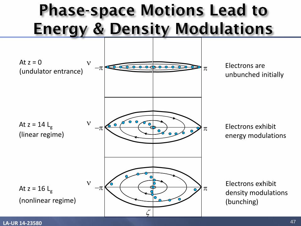
At z = 0 (undulator entrance)
At z = 14 Lg
At z = 16 Lg
n
n
n
Electrons are unbunched initially
Electrons exhibit energy modulations
Electrons exhibit density modulations (bunching)
LA-UR 14-23580 48
An initially unbunched beam develops energy and density modulations at saturation.

LA-UR 14-23580
The electric field associated with the radiation from the jth electron at time t
jj itiEtE exp)exp(0
N
j
jitiEtE )exp()exp(0
2
2
0
2
0
0
*
0
)exp(2
1
2
1 N
j
N
jk
kj
N
j
N
k
k
N
j
j iiEEZ
tEtEZ
I
kjfNNNZ
EI 1
2 0
2
0
The electric field associated with the radiation from N electrons
Radiation intensity from N electrons
The first term (scaling with N) corresponds to incoherent undulator radiation. The 2nd term (scaling with N2) corresponds to coherent bunched beam radiation.
Bunching factor
LA-UR 14-23580
E = Type equation here.
50
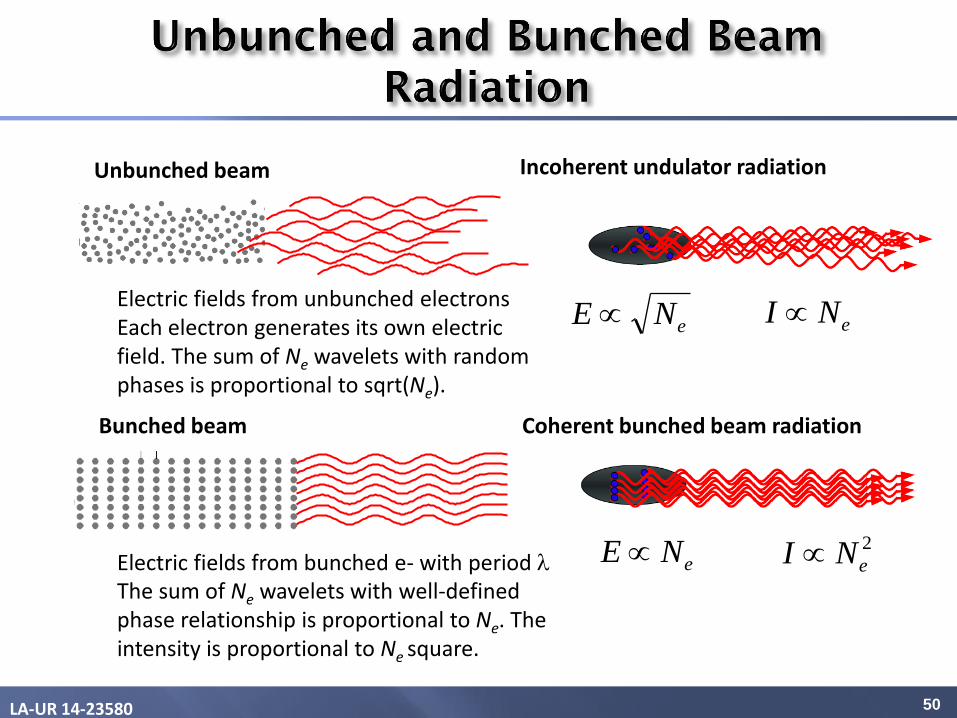
Incoherent undulator radiation Unbunched beam
Electric fields from bunched e- with period The sum of Ne wavelets with well-defined phase relationship is proportional to Ne. The intensity is proportional to Ne square.
Bunched beam Coherent bunched beam radiation
eNI eNE
2
eNI eNE
Electric fields from unbunched electrons Each electron generates its own electric field. The sum of Ne wavelets with random phases is proportional to sqrt(Ne).
LA-UR 14-23580 51
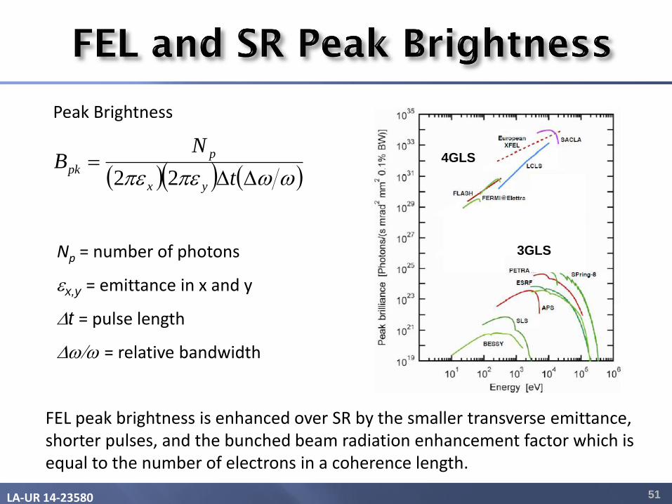
FEL peak brightness is enhanced over SR by the smaller transverse emittance, shorter pulses, and the bunched beam radiation enhancement factor which is equal to the number of electrons in a coherence length.
Peak Brightness
Np = number of photons
x,y = emittance in x and y
t = pulse length
/ = relative bandwidth
t
NB
yx
p
pk22
3GLS
4GLS
LA-UR 14-23580 52
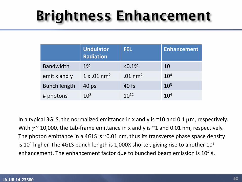
In a typical 3GLS, the normalized emittance in x and y is ~10 and 0.1 m, respectively.
With g ~ 10,000, the Lab-frame emittance in x and y is ~1 and 0.01 nm, respectively.
The photon emittance in a 4GLS is ~0.01 nm, thus its transverse phase space density
is 104 higher. The 4GLS bunch length is 1,000X shorter, giving rise to another 103
enhancement. The enhancement factor due to bunched beam emission is 104 X.
Undulator Radiation
FEL Enhancement
Bandwidth 1% <0.1% 10
emit x and y 1 x .01 nm2 .01 nm2 104
Bunch length 40 ps 40 fs 103
# photons 108 1012 104
LA-UR 14-23580 53
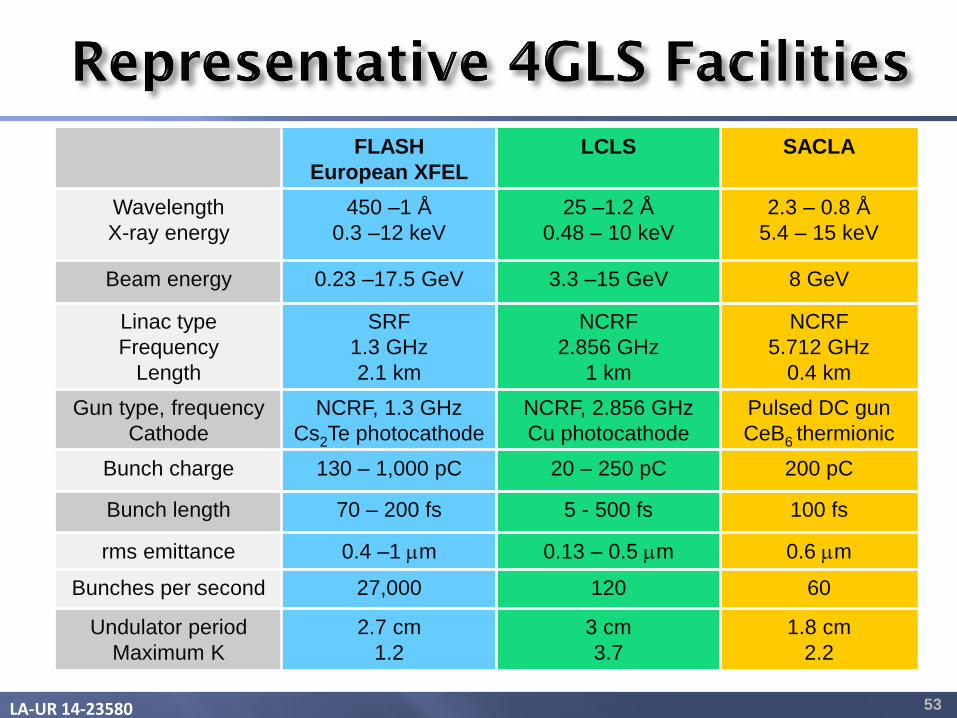
FLASH
European XFEL
LCLS SACLA
Wavelength
X-ray energy
450 –1 Å
0.3 –12 keV
25 –1.2 Å
0.48 – 10 keV
2.3 – 0.8 Å
5.4 – 15 keV
Beam energy 0.23 –17.5 GeV 3.3 –15 GeV 8 GeV
Linac type
Frequency
Length
SRF
1.3 GHz
2.1 km
NCRF
2.856 GHz
1 km
NCRF
5.712 GHz
0.4 km
Gun type, frequency
Cathode
NCRF, 1.3 GHz
Cs2Te photocathode
NCRF, 2.856 GHz
Cu photocathode
Pulsed DC gun
CeB6 thermionic
Bunch charge 130 – 1,000 pC 20 – 250 pC 200 pC
Bunch length 70 – 200 fs 5 - 500 fs 100 fs
rms emittance 0.4 –1 m 0.13 – 0.5 m 0.6 m
Bunches per second 27,000 120 60
Undulator period
Maximum K
2.7 cm
1.2
3 cm
3.7
1.8 cm
2.2
LA-UR 14-23580 54
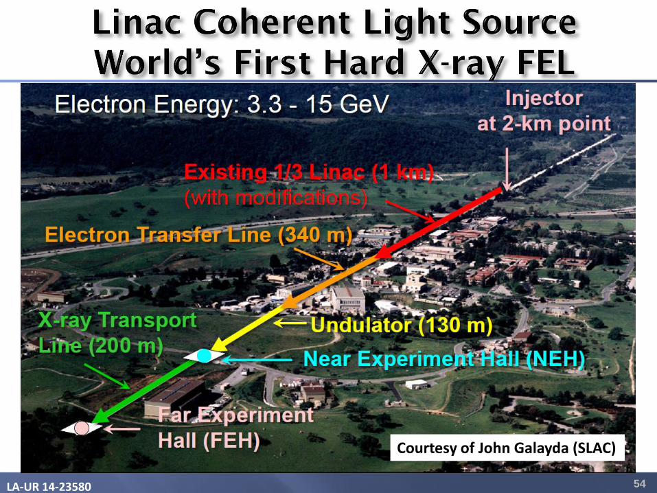
Courtesy of John Galayda (SLAC)
LA-UR 14-23580 55
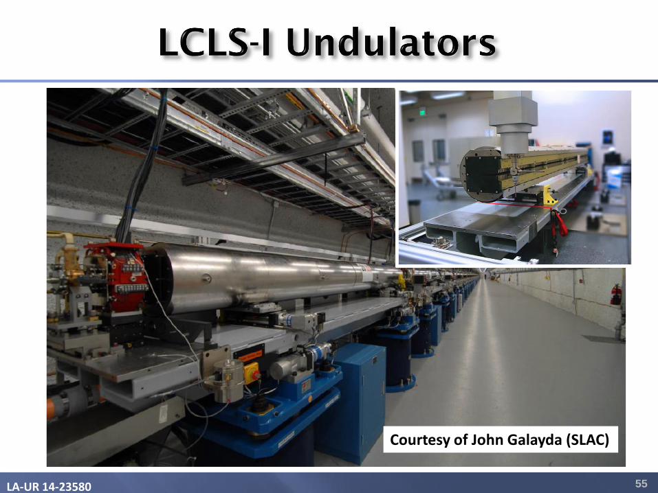
Courtesy of John Galayda (SLAC)
LA-UR 14-23580 56
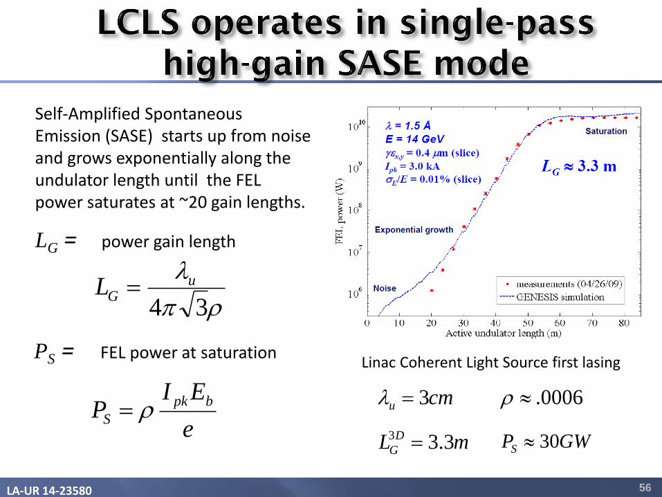
Self-Amplified Spontaneous Emission (SASE) starts up from noise and grows exponentially along the undulator length until the FEL power saturates at ~20 gain lengths.
e
EIP
bpk
S
LG = power gain length
PS = FEL power at saturation
0006.
Linac Coherent Light Source first lasing
GWPS 30
cmu 3
mL D
G 3.33
34
uGL
LA-UR 14-23580 57
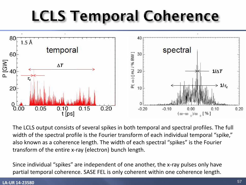
The LCLS output consists of several spikes in both temporal and spectral profiles. The full width of the spectral profile is the Fourier transform of each individual temporal “spike,” also known as a coherence length. The width of each spectral “spikes” is the Fourier transform of the entire x-ray (electron) bunch length. Since individual “spikes” are independent of one another, the x-ray pulses only have partial temporal coherence. SASE FEL is only coherent within one coherence length.
1/T
1/tc 1/tc
T
tc
LA-UR 14-23580 58
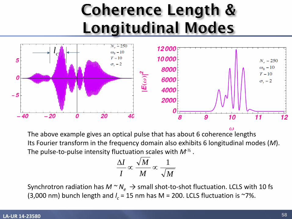
cl
The above example gives an optical pulse that has about 6 coherence lengths Its Fourier transform in the frequency domain also exhibits 6 longitudinal modes (M). The pulse-to-pulse intensity fluctuation scales with M-½ . Synchrotron radiation has M ~ Ne → small shot-to-shot fluctuation. LCLS with 10 fs (3,000 nm) bunch length and lc = 15 nm has M = 200. LCLS fluctuation is ~7%.
MM
M
I
I 1
LA-UR 14-23580 59
• Radiation from accelerator-based light sources (third and fourth generation light sources) share many features of conventional laser Gaussian beams, plus the major advantage of being tunable in the x-ray regions.
• An FEL is a classical device that uses relativistic electrons traversing an undulator in free space. The basic processes in an FEL are:
• Radiation slips ahead of electrons one wavelength every period (resonance condition that enables continuous energy exchange)
• Electrons gain or lose energy depending on phase (energy modulation) • Electrons bunch up with period of one wavelength (density modulation) • Coherent emission (N2 process) from bunched electron beams
• The 4GLS are X-ray FEL that produce tunable, fs coherent x-rays with peak
brightness ten orders of magnitude higher than that of undulator radiation.
• SASE has full transverse coherence but is partially coherent temporally.