vuv and x-ray free electron lasers · electron bunch in an storage ring (laser “bunch-slicing...
TRANSCRIPT

1
VUV and X-Ray Free Electron Lasers:
The Technology and Its Scientific Promise
William Barletta and Carlo Rizzuto
Sections I & III – Motivations & FEL Physics
List of symbols
fine structure constant
dimensionless vector potential aw
horizontal Twiss x
bunching parameter b
mean resolution error of BPMs BPMres
position error of BPMs BPMpos
remanent field BR
undulator magnetic field strength Bw
horizontal Twiss x
speed of light c
mean phase error in undulator
penetration depth δp
horizontal dispersion Dx
derivative of Dx D´x
FEL beam diameter on optic Dw
energy chirp from CSR E/E
beam emittance
electron charge e
beam energy E
peak electric field in gun Eo
normalized emittance n
energy in the FEL pulse EPulse
longitudinal space charge force Fsc
angle of incidence
j i

2
relativistic factor (E/ me c2)
optical function in transport H
magnetic coercivity HC
Alfven current at =1 IAo
beam current Ib
BBU threshold current IBBU
undulator parameter K
mean undulator strength Krms
undulator spatial frequency kw
gain length LG
mth
harmonic wavelength m
plasma wavelength P
radiation wavelength r
undulator wavelength w
root of gain equation
harmonic number m
electron mass me
number of electrons Ne
electron density ne
number of undulator periods Nu
radiation power P
input laser power Plaser
noise power Pn
pole roll angle error
BNP (or Pierce) parameter
quantum FEL parameter ´
atom density A
quality factor Q
dipole quality factor Qdipole
FEL energy constraint ratio r1
FEL emittance constraint ratio r2
FEL diffraction constraint ratio r3
classical radius of electron re
bend angle in undulator
bend angle in achromat

3
phase of ith
electron i
kick relative to each pole error j
mean energy spread of electrons e
bunch length z
relativistic plasma frequency p
distance along undulator z
mean longitudinal velocity <vz>
impedance of free space Zo
Rayleigh range ZR

4
I. Introduction: Why Free Electron Lasers?
I.A. Motivations
Chemical, physical, and biological processes are intrinsically dynamic in nature since
they are related to electronic and atomic structures that evolve with time. The
characteristic time scales span from a few femtoseconds, in the case of electronic
processes, to a few tens or hundreds of femtoseconds, as in the case of atomic and
molecular processes. Other phenomena, which control the behavior of critical systems,
may happen at relatively longer time scales, ranging from a few picoseconds to a few
hundreds of picoseconds or more. These phenomena include the dynamics produced in
phase transitions, such as those related to magnetic order or to superconductivity. The
nascent capability to measure these phenomena at the relevant time scales will open
completely new perspectives and analyses. In particular, the direct observation of
electronic processes, of structural dynamics and of dynamical critical phenomena (such
as phase transitions) represents an unexplored landscape in the study of condensed
matter. These possibilities were already evident to the inventors of the first coherent
sources of femtosecond optical pulses. Ultra-short pulses of coherent light have
generated remarkable scientific progress such as that which was recognized in the 1999
the Nobel Prize for Chemistry awarded to Ahmed Bewail for his pioneering work on the
application of ultra-short laser infrared spectroscopy to the study of the dynamics of
chemical bonds.
Currently available, fully coherent (laser) light sources emit radiation only in a limited
range of wavelengths. Their use is limited to optical and spectroscopic techniques in the
infrared, visible and near-ultraviolet range, excluding all the measurements needing
photons of energy higher than a few eV. There is therefore a strong scientific need for a
tunable, coherent light source with an energy range from the vacuum ultraviolet (VUV)
to the X-ray with a stable and well-characterized temporal structure in the femtosecond
and picosecond time domain. To this end, international research efforts are moving in
three main directions: 1) laser-driven light sources which use non-linear processes to
create very high harmonics, 2) interaction between an ultra-short laser pulse and an
electron bunch in an storage ring (laser “bunch-slicing technique”), 3) free electron lasers
(FELs). The first two techniques are able to produce radiation pulses in the femtosecond
time domain and in the soft X-ray region with a relatively low brilliance (i.e. a low useful
photon flux on the material under investigation). In contrast FELs can produce light
pulses with peak brilliance as much as ten orders of magnitude higher than the pulses
generated in present third generation synchrotron light sources and with photon energies
ranging from the VUV to the hard X-ray, i.e. from about 10 eV (120 nm) to 10 keV (0.12
nm).
The performance of synchrotron radiation sources are commonly characterized and
compared in graphs of the time-averaged flux (photons/s/mrad/0.1%BW) and brightness
(photons/mm2/mrad
2/0.1%BW) available for experiments as a function of X-ray energy.
More recently other metrics have been proposed such as the useful flux within the phase
space acceptance of a sample as small as a 50-100 micron protein crystal with a
mosaicity of several milliradians. With increasing scientific interest in sub-picosecond
pulses, the peak (or instantaneous) values of these metrics during a single pulse also

5
become important. Figure 11 compares the performance of several types of X-ray sources
from the point of view of peak brightness and pulse duration. A listing of operating FEL
facilities can be found on the internet at http://sbfel3.ucsb.edu/www/fel_table.html.
Figure 1. Brightness and pulse duration ranges of next generation light sources. The time average
brightness is the peak brightness times the duty factor.
Table 1. Additional characteristics of UV/X-ray sources
Maximum
Duty Factor
Laser
synchronization
Pulse
repetition rate
Storage rings ~10 –3
No 10 – 100 MHz
Slicing Sources ~10 –9
Limited 1 – 10 kHz
Energy Recovery Linacs ~10 –3
No 10 – 100 MHz
ERLs w. X-ray compression ~10 –8
Yes 10 kHz
SPPS ~10 –11
No 100 Hz
X-ray FELs ~10 –10
Some 100 – 1000 Hz
Laser Accel. Sources ~10 –12
Yes 1 – 10 kHz
1 Both the figure and table are reproduced from W. A. Barletta and H. Winick, “Introduction to special
section on future light sources,” Nucl. Inst. and Meth., A 500, (March 2003) 1 – 10.

6
The performance metrics of Table 12 are likely to be used increasingly to complement the
flux and brightness spectral curves that are already in general use, to assess the suitability
of source performance for experiments that depend on the peak or instantaneous values.
The prospects for the blossoming of a new field of ultra-fast UV/X-ray science based on
light produced by FELs (4th
generation sources) in physics, chemistry and biology based
on light produced by FELs (4th
generation sources) are indeed exciting. Taking a lesson
from the previous development of ring-based 3rd
generation light sources, one anticipates
that the real applications of FEL light sources will far surpass what is now predicted in
the perspective scientific cases. Nonetheless, such research is likely to remain a relatively
small part of the experiments that rely on storage ring-based synchrotron radiation
sources. Storage rings sources are now, and are highly likely to remain, the workhorses of
synchrotron radiation science for many years to come. By providing beams of radiation
over a broad spectrum from the sub-mm radiation to X-rays with high flux and brightness
and outstanding stability, reproducibility and reliability, storage rings sources will
continue to serve the needs of a vast and still increasing scientific and technical
community even while linac-based sources open up new scientific frontiers with their
sub-picosecond pulse duration and extremely high peak brightness and coherence.
I.B. What users want in a FEL-based light source
As a most general performance metric of next generation light sources based on FELs
and energy recovery linacs, users desire to have ≥1014
photons/sec in a 0.1% bandwidth
delivered onto the experimental sample with a time structure matched to the physical
process under investigation. This requirement can be expanded into requirements on
spectral properties, bandwidth, tunability, pulse intensity, pulse duration, pulse-to-pulse
stability, timing and synchronization, polarization, and repetition rate as described below.
Spectral properties
Processes of interest for investigation with FEL sources cover a large range of
wavelengths from10 eV (120 nm) to 10 keV (0.12 nm). Some experimentalists are likely
to want the same degree (or more) of spectral stability without monochromatization as is
presently available from storage ring sources with monochromators.
Bandwidth
Not surprisingly, users request minimum spectral bandwidth and/or controlled chirp:
bandwidth at the transform limit allows the user to isolate spectral shifts; spectral chirp
allows correlating energy with time in new ways. For experiments measuring core level
shifts 0.1-0.5 eV bandwidths are typical; for NEXAFS experiments a bandwidth of ≤ 0.1
eV is highly desirable. The most demanding requirement are for measurements of
resonant inelastic X-ray scattering (RIXS) which calls for ultra-high resolution,
~10-5
.
Tunability
Spectroscopy demands tuning near to edge transitions. Typically rapid tuning should be
possible at the level of the spectral bandwidth. Tuning over tens of eV should be possible
on the time scale of minutes.
2 Id.

7
Pulse intensity
Even in the investigations of linear phenomena pulse intensities must be sufficient to
obtain measurable photoemission signals and to record absorption contrast changes,
without sample damage. The field intensities of the X-ray pulse must also be sufficient
low to avoid Stark shift and field broadening of sample line widths. Typically such
experiments in the linear regime cannot tolerate pulse intensities exceeding 107 – 10
8
photons on the sample per sub-picosecond pulse and prefer less intense pulses spaced by
the relaxation time (~0.1 to 10 s) of the process under investigation. Investigating non-
linear dynamics and single pulse imaging experiments require as many as 1012
UV/X-ray
photons in a single ultra-fast pulse, the duration of which is limited by the ablation time
of the sample or by the hydrodynamic expansion time over a resolution element.
It is these large single-pulse intensities that strongly disfavor storage rings with time-
gated detectors as an appropriate source for experiments on the 100 fs time scale.
Quantum electrodynamics limits the number of photons that an electron can radiate as it
travels in its roughly circular orbit in a synchrotron light source to ~ -1
per revolution.
Therefore the intensity of the UV/X-ray pulses depends linearly on the stored beam
current, Ib, in the storage ring. Likewise, the discrete nature of the radiation of photons as
the electron beam bends around the ring leads to the following effects on the electron
beam:
1) to spread the energy of the beam around its central value and thereby
to increase the bunch length,
2) to increase the beam emittance, , (the product of beam size and
divergence) as ~E2
3 where E is the beam energy and is the
bending angle of bend in each achromat of the storage ring lattice.
The spread in beam energy broadens the spectral width of the emitted radiation while the
beam size and emittance set the effective source size and divergence of the radiation.
Thus, the current in the electron beam and the emittance of the electron beam determine
the average flux on an experimental sample. Both collective instabilities and operating
costs put practical limits on the stored current in storage rings. Although the low energy
rings in B-factories now operate with ~3 A of stored current, for hard X-ray sources in
which minimizing beam emittance is crucial, a more practical means of increasing beam
currents above 500 mA and, therefore, time averaged brightness or flux (photons/s/mm2)
may be to use a recirculating linac configuration energy to recover the energy3 carried by
the electron beam rather than the beam itself. The Energy Recovery Linac architecture
increases UV/X-ray brightness at most linearly with the electron current; however, the
most dramatic increase in the brightness per unit beam current can be obtained through
the coherent radiation process that underlies the free electron laser amplifier.
Pulse-to-pulse stability
Stability of both intensity and spectral characteristics is viewed as essential to studies of
linear processes, since the radiation pulse will excite only a small fraction of the
molecules or materials. Users of third-generation light sources have become accustomed
3 Energy recovery linacs (ERL) were first proposed by M. Tigner, “A possible apparatus for clashing-beam
experiments”, Nuovo Cimento 37, 1228 (1965).
8
to 0.1% stability, a level that allows real time subtraction of backgrounds in pump
on/pump off experiments.
Pulse duration
Pulses of 20 - 200 fs X-ray pulses are needed to match the characteristic time scales of
the dynamic processes under investigation. In the future, users may request4 pulses as
short as 100 attoseconds. Pulse durations on this time scale are far beyond the
capabilities5 of standard synchrotron light sources and are a principal compelling reason
to consider linac-based sources for studies of ultra-fast processes.
Even in specially designed storage rings with a suitably isochronous, low momentum
compaction6 lattice, pulse durations would be limited to ~1 ps by coherent synchrotron
radiation (CSR)7. The CSR
8,9,10,11 can rapidly drain energy from the electron beam,
creating an energy chirp from head to tail and increasing beam emittance.
For electron beams with an energy exceeding 1 GeV and with a duration less than 1 ps,
carrying 1 nC, CSR can spread the bunch energy by ~1% in a fraction of a single turn.
Consequently in the design of an FEL facility dedicated to studies of ultra-fast dynamics
(<<1 ps) one is naturally driven to the linac-based free electron laser. Even in such FEL
systems, CSR is an important limiting phenomenon in the design of beam bunchers and
beam spreaders which direct the full energy beam to different FEL lines.
Timing and synchronization
A large class of experiments (pump-probe) initiate a time-evolving process in the sample
with another laser or UV/X-ray pulse. Such pump-probe experiments demand lasers
4 “Now, a new area of experimental physics is emerging, one sufficiently radical to be defined by its own
prefix—“attosecond science”. By using femtosecond optical pulses to generate wave packets in the soft x-
ray region, where wave cycles last for only about 50 attoseconds (as) or 50 x 10-18 seconds, it should be
possible to produce multi-cycle x-ray pulses with sub-femtosecond durations. In this issue, Drescher et al.
report a first step in this direction. The authors have both created and measured x-ray pulses with durations
below the carrier wave period of the original optical pulse.” D.T. Reid, “LASER PHYSICS: Toward
Attosecond Pulses,” Science 291. No. 5510, 9 March 2001, pp. 1911 – 1913 and M. Drescher, M.
Hentschel, R. Kienberger, G. Tempea, C. Spielmann, G. A. Reider, P.B. Corkum, F. Krausz, “X-ray Pulses
Approaching the Attosecond Frontier,” Science 291, 1923 (2001). 5 In storage ring light sources the duration of radiation pulses equals that of the electron bunches, sz. Once
the bunches have circulated for an energy damping time, the quantum nature of synchrotron radiation
spreads the electron energy to a value roughly equal to the geometric mean of the beam energy and the
critical energy of the synchrotron radiation in the average bending field of the ring. This spread is ~ 10-4
to
10-3
, causing the injected electron pulses to lengthen to tens of picoseconds. Tuning the lattice of the ring
to yield nearly isochronous transport may allow high current bunches with <10 ps duration. In that instance
machine operation has been seen to be difficult, unreliable, and incompatible with the needs of most users. 6 The momentum compaction, usually denoted by , is the fractional change in orbit length around the
storage ring with fractional change in energy beam energy. 7 CSR occurs when synchrotron radiation with a wavelength roughly equal to z , emitted from the back of
electron pulse can propagate through the vacuum chamber to overtake and interact strongly with the head
of the pulse as the beam passes through a dipole. See L.I. Schiff, Rev. Sci. Instr. 17, 6 (1946) 8 “Shielded Synchrotron Radiation and Its Effect on Very Short Bunches”, R. L. Warnock, SLAC PUB-
5375, November 1990 9 Also M. Dohlus, T. Limberg, “Emittance Growth due to Wake Fields on Curved Bunch Trajectories,”
XVIII International Free Electron Laser Conference, (1996), Rome Italy 10
J.S. Nodvick and D.S. Saxon, Phys. Rev. 96, 180 (1954) 11
E.L. Saldin, E.A. Schneidmiller, and M.V. Yurkov, Nuc. Inst. Meth. A 398, 373 (1997)

9
synchronized12
to within <20 fs of the UV/X -ray pulse. Other experiments such as single
pulse imaging some require no synchronization signal.
Polarization
A dedicated FEL facility should offer complete flexibility to the user in the choice of the
polarization of the radiation. Complete right-handed and left-handed circular
polarizations are needed for polarization blocking and dichroism experiments.
Pulse repetition rate
Ideally the pulses of radiation should be supplied to the user at a rate limited only by the
relaxation times of the processes under investigation. Consequently, rates as high as ~10
MHz are interesting for a large class of experiments. In those experiments that demand
single pulse intensity leading to sample damage, the relevant maximum repletion rate will
be set by considerations such as how fast the sample can be replaced or annealed.
12
Ideally the accuracy of synchronization and timing should be an order of magnitude than the X-rat pulse
duration. See J. N. Corlett, W. Barry, J. M. Byrd, R. Schoenlein, and A. Zholents, “Synchronization of X-
ray Pulses to the Pump Laser in an Ultrafast X-ray Facility”, Proceedings of EPAC 2002, Paris, France.

10
III. Physics of Free Electron Lasers
As already discussed in Section I, for strong-field and single pulse experiments that
require more than ~108 X-ray photons in sub-picosecond pulses, it is not sufficient to rely
on the spontaneous, incoherent emission of synchrotron radiation. As quantum
electrodynamics limits the radiation from a single electron to ~ photons per radian of
bending, controllable amplification of the radiation passing through the undulator is
required. With the FLASH FEL13
at DESY and the LCLS14
and XFEL15
under
construction at SLAC and DESY respectively spatially coherent sources of soft and hard
X-rays seem now to be within reach using the free electron laser mechanism16
operating
in the Self Amplification of Spontaneous Emission (SASE) mode. However, for
experiments requiring full spatial and temporal coherence plus femtosecond level timing
and synchronization, an alternative FEL architecture that uses a seed laser to initiate the
FEL process appears preferred as in the FERMI@Elettra and BESSY FEL projects.
III.A. Basic principles of the FEL
The basic principle of the high gain free electron laser17,18
is both well known and tested
experimentally in numerous experiments at wavelengths from the millimeter waves to ~
100 nm. The best known and first tested instance of a free electron laser operating with
high single pass gain was the master oscillator-power amplifier configuration that was
demonstrated in experiments19
by a joint Lawrence Berkeley- Lawrence Livermore
13
“FLASH is a user facility providing laser-like radiation in the VUV and soft X-ray range to various user
experiments in many scientific fields. It is also a pilot facility for the future XFEL.” http://vuv-fel.desy.de/ 14
The LCLS homepage is http://www-ssrl.slac.stanford.edu/lcls/. 15
The European X-Ray Laser Project XFEL, http://xfel.desy.de 16
For a reference to FEL activities around the world including recent experimental progress toward
demonstrating FELs at short wavelength, see http://sbfel3.ucsb.edu/www/vl_fel.html 17
The free electron laser was first proposed by John Madey in 1971; see J.M.J. Madey, J. Appl. Phys., 42,
1906 (1971). Madey’s concept was itself predated by similar concepts for the amplification of microwave
radiation; R.M. Philips, IRE Trans. Electron Devices, 7, 231 (1960). Madey and his co-workers
demonstrated both the operation of an FEL amplifier and an FEL oscillator. L.R. Elias, W.M. Fairbank,
J.M.J. Madey, H.A. Schwettman and T.I. Smith, Phys. Rev. Lett. 36, 717 (1976) and D.A.G. Deacon, L.R.
Elias, J.M.J. Madey, G. J. Ramian, H.A. Schwettman and T.I. Smith, Phys. Rev. Lett. 8, 892 (1977). 18
Early analyses of the systematics of the FEL process including the derivation of the high gain regime are
given in A Bambini, A. Renieri, S. Stenholm, “Classical theory of the free electron laser in a commoving
frame”, Phys. Rev. A, Vol. 19, n.5, (1979) and W.H. Louisell, J.F. Lam, D.A. Copeland, W.B. Colson,
“Exact classical electron dynamic approach for a free-electron laser amplifier”, Phys. Rev. A, col. 19, n.1,
(1979). Another important early analysis was given by N.M . Kroll, P.L . Morton and M.N . Rosenbluth,
IEEE J. Quantum Electron. QE 17 (1981) 1436. It was this latter paper that provided the basis of the
computer model for designing the first successful high gain experiment. 19
The LBNL-LLNL experiment called ELF (Electron Laser Facility) was aimed at showing that long (~50
ns), high current pulsed could be transformed into very high power, high frequency microwaves that would
be used to drive a high gradient rf-accelerator structure at more than 100 MeV/m for a TeV linear collider.
This Two-Beam Accelerator (TBA) concept was invented by A.M. Sessler, who conceived of ELF as the
first stage in the realization of the TBA. See A. M. Sessler, “Laser Acceleration of Particles,” AIP Conf.
Proc. 91, 154-159 (1982).
Other early experiments at low wavelengths include D.A. Kirkpatrick, G. Bekefi, A.C. DiRienzo, H.P.
Freund, and A.K. Ganguly, “A Millimeter and Submillimeter Wavelength Free-Electron Laser,” Phys.

11
Laboratory collaboration in the mid-80’s. While these experiments were performed at a
wavelength of 8 mm (35 GHz) in the presence of a waveguide, they verified all the basic
predictions of the 1-dimensional theory formulated by Bonifacio, Pellegrini and
Narducci20
modified to include waveguide effects.
In traversing a undulator – a periodic magnetic field device (or structure) - an electron
bunch with a relativistic factor, radiates at a wavelength (in the beam frame) that is the
back scattered value, w/, of the Lorentz contracted period, w of the static magnetic
field of the undulator. To the observer in the laboratory frame, the radiation is Doppler
upshifted by a factor 2
rms), where rms is the rms angle by which the electrons bend
in the undulator.
Since the electrons will have an rms transverse velocity in the undulator, the longitudinal
velocity is reduced such that the radiation emitted in the forward direction will slip
forward with respect to the beam. If the electrons oscillate in phase with the field, they
will continually lose energy to the field leading to the FEL instability. This resonance
condition is that the electrons slip one optical period per undulator period. Thus, the
resonance condition among the radiation wavelength, r, the undulator21
wavelength and
the energy of the electrons is
lr =lw2g 2
1+Krms2( ) (1)
where Krms equals K 2 (= aw) for a planar undulator and equals K for a helical
undulator; mec2 is the energy of the electron beam. The dimensionless vector potential
of the undulator field, K, is determined by the maximum magnetic field on axis, Bw and
the undulator period, w. In physical units,
K = 0.934 w[cm] Bw[T]. (2)
III.A.1. Gain & bunching
The basic functional mechanism of the FEL, as described in the 1-dimensional (1-D)
theory, is a collective instability of the electron bunch as it traverses a periodic magnetic
field structure. At the beginning of the process, the initial radiation (either from a master
oscillator or from the incoherent spontaneous synchrotron radiation) induces an energy
modulation (micro-bunching) in the bunch that is converted to a density modulation at
the radiation frequency. The fraction, ƒ, of the electrons in the “micro-bunch” radiate
coherently with intensity proportional to Ne2(where Ne is the number of electrons). The
Fluids B 1 (1989) 1511. Also, D.A. Kirkpatrick, G. Bekefi, A.C. DiRienzo, H.P. Freund, and A.K.
Ganguly, “A High Power 600 mm Wavelength Free-Electron Laser,” Nucl. Inst.. Meth. A 285 (1989) 43. 20
R. Bonifacio, C. Pellegrini, and L. Narducci, Optics Comm. 50, 373 (1984), hereinafter BPN. An
excellent elaboration of the basics of free electron laser theory is presented in the review article, R.
Bonifacio et al., La Rivista del Nuovo Cimento, 13, N. 9, (1990). Another lengthy exposition from first
principles is E. L. Saldin, E.A. Schneidmiller, M.V. Yurkov, “The physics of free electron lasers. An
introduction,” Physics Reports, 260, Issue 4-5, (1995) 187-327 21
While insertion devices frequently use the word “undulator” for K≤1 and use “wiggler” for K>1, this
paper uses the word undulator for all values of K. Note that in FELs K > 1 are strongly preferred.

12
coherent radiation augments the incident radiation (or initial noise signal) further
increasing the micro-bunching leading to yet more coherent radiation. As the electrons
and the radiation propagate together down the undulator, the result is an exponentially
growing radiation field with a power that grows as
P = aPnez /Lg (3)
In equation (3) Pn is the initial signal strength, is a coupling coefficient between the
signal strength and the dominant mode, and z is the distance along the undulator. LG is
the gain length, that is, the distance for an e-folding of the radiation intensity.
In particular, when an electron beam traverses the undulator with a period, w,
synchrotron radiation is generated at the resonant wavelength, r. As the signal grows,
the pondermotive potential, created by the undulator field and the radiation field, bunches
the electrons periodically on the wavelength scale of the resonant (sometimes called
optical) wavelength. The current compression due the free electron laser action can be
computed from the bunching parameter, b, which is the ensemble average
b = eiq j (4)
where jis the phase of the jth electron with respect to the radiation frequency. For an
unbunched beam b = 0 while for a beam bunched to a delta function of current b = 1.
The strong FEL bunching is evidenced by the fact that when the gain saturates, the
bunching factor reaches a maximum bmax ~ 0.8 regardless of the actual values of the
initial current, w, or r. Bunching on the scale of an optical wavelength is clearly seen
in the GENESIS simulation (Figures 4 and 5) from the DESY Technical Design Report.22
Figure 4. GENESIS calculations of particle positions in the transverse direction y and in z
at three locations along the undulator. Left panel is at the entrance to the undulator; the
right panel is at saturation. The central panel is at an intermediate position.
22
TESLA Technical Design Report, Part V, The X-Ray Free Electron Laser, Editors: G. Materlik Th.
Tschentscher, p.25 http://tesla.desy.de/new_pages/TDR_CD/PartV/fel.html (2001)

13
Figure 5. GENESIS calculation23
of the longitudinal phase space at the location of maximum
bunching
The gain of the FEL and the speed of the bunching process in a cold (zero emittance)
beam with no incoherent energy spread is described by the BPN universal scaling
parameter24
, ;
r =aww plw
8pc
æ
è ç
ö
ø ÷
2 / 3
µ I1/3Bw
2/3lw4 / 3
g (5)
where p is the relativistic plasma frequency, aw is the dimensionless vector potential of
the undulator and kw is the undulator spatial frequency.
aw ≈ 0.66 Bw(Tesla) lw (cm) (6)
kw ≈
2 π
lw
(7)
and
w p
2 =4pnerec
2
g 3 (8)
In equation (8) ne is the electron density and re is the classical radius of the electron. The
electron density is related to the beam radius rb and the beam current by
I = pcenerb2 (9)
The e-folding (gain) length, LG, for the power carried by the electromagnetic field as
computed from the 1-dimensional theory is given by the general expression,
23
Figure 5 is extracted from presentation by S. Becker, “Table-top Free Electron Laser,” (2006) 24
BNP paper. In this paper, the authors graciously refer to this parameter as the Pierce parameter due to its
similarity to a parameter in microwave tube theory. It is also referred to in the literature as the universal
FEL parameter. The present authors have used the term BNP parameter recognize the first introduction of
this parameter in the FEL analysis.

14
LG =lw
4pr Im(2m) (10)
where Im(µ) is the solution to the (cubic) eigenvalue equation for the FEL instability
written for the field intensity. In the cold-beam, 1-D limit, Im(µ) = √3/2.
The line width, , of the output radiation from the SASE process in the classical
regime is the root mean square of the homogeneous and inhomogeneous broadenings.
The homogeneous width is equal to and is related to the temporal spikes that
characterize SASE output. Inhomogeneous broadening arises from errors in the beam
energy, undulator field and undulator wavelength; their contribution to can be
found by differentiation of the resonance condition.
Another experimentally verified feature of the high gain FEL is that the rate of the
bunching action is proportional to w. Hence bunching actually proceeds more rapidly
as the input current increases. It is this characteristic that makes the FEL buncher25,26
so
attractive in comparison with other bunching schemes when the final peak value of the
bunched current must be extremely large or when the bunch length must be very short.
Yet another feature of the FEL that compares favorably with respect to other bunching
schemes is that the length over which bunching occurs scales favorably (increases only
linearly with increased beam energy). The FEL action does, however, induce an energy
spread in the beam that is proportional to the gain. By terminating the undulator before
the FEL process saturates one can a) maximize current multiplication, b) keep the
induced energy variation small, and c) minimize the length of the undulator. All of these
considerations play actively in the design of both FEL bunchers and high-gain harmonic
generation (HGHG) systems such as the FERMI FEL (to be described in detail later)..
III.A.2 Limitations on the FEL process
As the electron beam characteristics depart from the cold beam limit, the rate of the FEL
bunching process, and consequently the FEL gain, can be strongly and adversely
affected. Specifically if the spread in longitudinal velocities <vz> of the beam electrons is
so large that the longitudinal drift of electrons is a large fractionr as the beam
propagates, the gain will be strongly suppressed. The spread, <vz>, at the entrance to the
undulator arises from the incoherent energy spread in the beam and from the beam
25
H. D. Shay, et al., “Use of a FEL as a Buncher for a TBA Scheme, ” Proc. of the Int. FEL Conference,
(Paris, 1990). 26
W. A. Barletta, R. Bonifacio, P. Pierini et al, “An rf-linac, FEL buncher,” Nucl. Inst. And Meth. A, 329,
Issues 1-2, 1993, pp. 348-360. This concept was applied to the generation of femtosecond X-ray pulses in
W. A. Barletta, R. Bonifacio, P. Pierini, “High brilliance, femtosecond x ray sources with FEL assist,”
Proc. of 4th Generation Light Sources Workshop, Stanford, CA, 24-27 Feb. 1992, SSRL Report 92/02
“ We describe EFSX … to produce multi-kiloampere pulses … in the generation of extremely short bursts
of X-rays. The key technical concept, the use of the free electron laser as a bunching mechanism … As
laser photo-cathode sources of beams evolve to yield ever better emittances, the EFSX could be easily
retrofitted to furnish the drive beam for an efficient x ray free electron laser.” These early ideas matured
into the ESASE concept discussed later in this review.

15
emittance, . We expect the FEL to be insensitive to energy spreads and variations as
long as
(11)
To satisfy the high gain FEL conditions, the phase area of the electron beam should be
smaller than that of the diffraction-limited radiation; i.e.,
r2 = 4penlrg
< 1 (12)
where n is the normalized emittance of the electron beam. In optical FELs using fine,
very low emittance beams the gain can be reduced and the rate of bunching will be
decreased if the radiation diffracts out of the electron beam too rapidly. Specifically the
Rayleigh range of the radiation should exceed LG; i.e.,
r3 = LG
ZR < 1. (13)
The constraints (11), (12), (13), and the resonance condition (1) are not all independent.
One can easily show that
r1 =1
4r2
2r3 (14)
The sensitivity of the FEL gain function Im() to the variations in beam emittance and
energy spread can be characterized27
in terms of these dimensionless parameters. The
results for the case of weak and strong diffractive effects (small and large r3) are shown in
Figure 6.
Figure 6. Gain surface, Im µ, versus scaled emittance and energy spread for two values of
the diffraction parameter, r3
27
W. A. Barletta, A. M. Sessler, L-H Yu, "Physically transparent formulation of a free-electron laser in the
linear gain regime," Nucl. Inst. and Meth. A331 (1993) 491-495); Figure 6 is reproduced from this paper.
The analysis of this paper is based on a numerical model and fitting of earlier analyses of L.-H. Yu, S.
Krinsky, and R. L. Gluckstern, Phys. Rev. Lett. 64, 3011 (1990) and of Y.-H. Chin, K.-J. Kim, and M. Xie,
LBL Report 30673 (Sept. 1991)

16
III.A.2.a Space charge effects
In multi-kiloampere beams at relatively low energy (<100 MeV), the debunching effects
of longitudinal space charge forces can compete with the bunching action of the FEL
process. The longitudinal space charge force, Fsc, varies as -1/3
; therefore, in GeV beams
it is completely negligible in the FEL process. Although space charge waves driven by
coherent synchrotron radiation can filament the longitudinal phase space in bunch
compressors as described in Section IV.D.
To evaluate the effects of space charge at low beam energy it is not sufficient to consider
the free space action of Fsc; one must include space charge in the pendulum equation that
governs the FEL instability. In their analysis28
, Murphy, Pellegrini and Bonifacio find
that the FEL process tends to be stabilized by space charge terms that are proportional to
4(1+K2/2)/ K
2; hence, they conclude, the space charge effects at resonance are
negligible for systems with < 0.01. They also find that unlike the case without space
charge, there is a lower negative value of detuning (r) beyond which the process is
stabilized (no growth of the FEL signal).
A fundamental physical argument also provides a condition under which space charge
effects are negligible; i.e., the FEL gain length (computed without space charge) should
be much less that the plasma wavelength, P. Equations (5), (8), and (10) imply that
. (15)
III.A.3 Initiation of the FEL process
FEL amplifiers can start operation by amplifying the incoherent shot noise29
that is
spontaneously radiated30,31
by the electrons in the beam as they enter the undulator. As
the electron beam and the radiation co-propagate through the undulator, the radiation
slowly slips through the electron beam in accordance with the resonance condition and
the radiation power grows exponentially. This process, called Self Amplification of
Spontaneous Emission (SASE), results in a high power output with very large temporal
fluctuations in the radiated power during the pulse. For single-shot experiments, and
those that do not require temporal coherence, such very high power pulses are ideal for
studying non-linear effects in materials. SASE sources, however, may be inconsistent
with the characteristics of the radiation demanded by experiments that require a high
degree of pulse-to-pulse temporal reproducibility or a high degree of temporal coherence.
28
J. B. Murphy, C. Pellegrini and R. Bonifacio, “Collective Instability of a Free Electron Laser including
Space Charge and Harmonics,” Optics Comm. 53, no.3, p. 197 – 202, (1985) 29
Shot noise is the term that describes the random statistical fluctuations in the incoherent synchrotron
radiation due to the random arrival time of the electrons in the beam. The phenomenon is intrinsically
quantum mechanical as the beam current is carried by a finite number of quanta (electrons). See
http://qwiki.caltech.edu/wiki/Shot_Noise 30
"Spectrum, temporal structure, and fluctuations in a high-gain free-electron laser starting from noise", R.
Bonifacio, L. D. Salvo, P. Pierini, N. Piovella, C. Pellegrini, Physical Review Letters, 74, pp. 7073, (1994) 31
“Shot Noise Startup of the 6 nm SASE FEL at the TESLA Test Facility”, P. Pierini and W.M. Fawley,
Proceedings of the 17th Int. Free Electron Laser Conf. Nucl. Instr. Methods Physics Res. A375 (1995)

17
The large fluctuations in the SASE process are nicely illustrated in Figure 7a, which
displays experimental results32
from the Tesla Test Facility FEL (now FLASH). The
calculated temporal structure of X-ray FELs that start from shot noise is illustrated in
Figure 7b. Direct measurements of such behavior are presently beyond experimental
capabilities.
a) b)
Figure 7 a) “SASE intensity versus bunch charge measured at TTF FEL. The straight line is the
spontaneous intensity multiplied by a factor of 100. To guide the eye, mean values of the radiation
intensity are shown for some bunch charges (dots). The vertical error bars indicate the standard
deviation of intensity fluctuations, which are due to the statistical character of the SASE process.”
b) 1-D simulation the temporal structure of a “typical” SASE FEL in the EUV at saturation from
Saldin et al.33
In the cold beam limit, the homogeneous line width of the SASE output is ~. Effects
such as magnetic field errors, beam misalignments and energy fluctuations within the
pulse will lead to inhomogeneous broadening of the line width by am amount calculable
from the derivatives of the resonance condition with respect to the relevant variable.
Recently, Bonifacio, Piovella and Robb have shown34
that if the mean number of photons
emitted per electron (at saturation) is much less than one, strong quantum effects modify
the output of the FEL. Quantitatively, they introduce a parameter35
, , defined as the
32
Figure 5a and caption are taken from J. Andruszkow et. al., “First Observation of Self-Amplified
Spontaneous Emission in a Free-Electron Laser at 109 nm Wavelength,” Phys. Rev. Lett., Vol. 85, Num.
18, p. 3825, 30 October 2000. See also M.J. Hogan, C. Pellegrini, J. Rosenzweig, G.A. Travish, A.
Varfolomeev, S. Anderson, K. Bishofberger, P. Frigola, A. Murkoh, N. Osmanov, S. Reiche, and A.
Tremaine, “Measurements of High Gain and Intensity Fluctuations in a SASE FEL,” Phys. Rev. Lett. 80
(2) (1998) 289. 33
E. L. Saldin, E. A. Schneidmiller and M. V. Yurkov, “Statistical properties of radiation from VUV and
X-ray free electron laser,” Opt. Comm., 148, Issues 4-6, (1998), 383-403. 34
R. Bonifacio, N. Piovella, G. Robb, R. Bonifacio, N. Piovella, G. R. M. Robb, Nucl. Inst and Meth. A
543, 645 (2005); R. Bonifacio, “Quantum SASE FEL with laser wiggler ,” Nucl. Inst. and Meth. A, 546, 3,
p. 634-638 (2005) See also N. Piovella, G.R.M. Robb, “Quantum theory of SASE FEL,” A 543 (2005) 645–652 35
This parameter was first introduced by R. Bonifacio, F. Casagrande, Opt. Comm. 50, 251 (1984) and R.
Bonifacio, F. Casagrande, Nuc. Inst and Meth. A 237, 168 (1985). Another early formulation of a quantum
mechanical theory of the FEL was published by G. Preparata, “Quantum Field Theory of the Free Electron
Laser”, Phys. Rev. A, 38, (1988). Other quantum mechanical descriptions of the FEL process have been
published by E. M. Belenov, S. V. Grigorev, A. V. Nazarkin, and I. V. Smetanin, JETP 78, 431 (1994) and

18
usual FEL parameter, times the ratio of the electron energy and the photon energy.
Moreover, represents the maximum number of photons emitted per electron. The
classical FEL regimes occurs when >>1. They prove that when 1 the broad
superposition of chaotic series of random spikes that characterizes SASE shrinks to a
very narrow spectrum of emitted radiation with extremely high peak power as shown in
Figure 836
. The nature of the transition from the classical regime to the quantum regime
can be seen in Figure 8c, which shows the imaginary part of the unstable root of the cubic
equation that describes the FEL gain in the 1-D limit as a function of the energy detuning
parameter,
d = (go - g) /rgo.
(c)
Figure 837
. Numerical solutions 1-D FEL field equations in the classical and quantum regimes:
Graphs (a) and (b) show the scaled field intensity |A|2(z1) after 50 gain lengths when the system
evolves classically ´ and quantum mechanically ´0.05, respectively. z1 is the retarded
time. Graph (c) The imaginary part of the unstable root of the cubic equation v.
d ; for
1/r = 0;
(a) 0.5, (b) 3, (c) 5, (d) 7, (e) and 10, (f).
Unfortunately the predicted gain lengths in the quantum regime are impractically long,
unless the FEL undulator is itself intense electromagnetic radiation. Indeed, Bonifacio
has proposed38
just such a scheme to test quantum SASE. While these ideas are intriguing
C.B. Schroeder, C. Pellegrini, P. Chen, Phys. Rev. E 64, 056502 (2001). However these earlier papers do
not treat the peculiar characteristics of SASE systems operating deep in the quantum regime. 36
Id. 37
Id. 38
R. Bonifacio, “Quantum SASE FEL with laser undulator,” Nucl. Inst. and Meth. 546 (3), pp. 634-638
(2005)

19
conceptually, present day FEL facilities must be based on classical FELs with
conventional undulator magnets.
The practical alternative to produce narrow bandwidth, temporally coherent soft X-ray
radiation from an FEL is to use a master oscillator-driven, power-amplifier configuration.
In this configuration the temporal coherence is determined by the properties of the master
oscillator or seed laser. Sincrotrone Trieste has adopted this approach implemented in its
FERMI @ Elettra project. The main requirement for the seed laser is to deliver
sufficiently high peak power (~100 MW) in the UV, at wavelengths tunable over a rather
large range, 240-360 nm, with variable pulse duration as required by the scientific
application program of the FEL facility. For the FERMI FEL this range is 100 fs to 1 ps.
Obviously, all input laser characteristics – particular the central wavelength – must be as
stable as practically obtainable. Moreover the timing jitter must be small compared with
the pulse length of the laser output.
III.A.4. Output power and saturation
As the electrons and the radiation propagate through the undulator, the radiation power
grows exponentially as
P(z) = Poez /LG < Psat (16)
until the power approaches its saturation value, Psat after passing a distance Zsat through
the undulator. The initial power is the integrated shot noise incoherently radiated into the
dominant growing mode by the electrons passing through the first gain length. In the 1-D
limit, the noise power39
is
Po »1
9
æ
è ç
ö
ø ÷
r2cEbeam
lr. (17)
In the 1-D, cold beam limit (ideal beam) the output power at saturation is determined by
the FEL scaling parameter ;
Psat,1-D = Pbeam (18)
Simulations40
with the simulation code GINGER show that this value is a conservative
estimate of the shot noise from a non-ideal beam. In the presence of strong 2-dimensional
effects, the corresponding expressions41
for the output power of the FEL at saturation
given are not as easily interpreted. One can, however, rewrite these expressions in a form
more readily understood in terms of the predictions of the 1-dimensional theory. In
particular the approximate expression of Chin, Kim, and Xie reduces to
39
M. Xie, “Design Optimization for an X-Ray Free Electron Laser Driven by SLAC Linac,” Proc. IEEE
Part. Accel. Conf. (1995) 40
W.M.Fawley et al., Proc. IEEE Part. Accel. Conf. (1993), 1530 41
L.-H. Yu, S. Krinsky, and R. L. Gluckstern, Phys. Rev. Lett. 64, 3011 (1990) and Y.-H. Chin, K.-J. Kim,
and M. Xie, LBL Report 30673 (Sept. 1991) and Proceedings of the FEL 1991 Conference, Santa Fe, NM

20
Psat;2-D =Im m( )
32
æ
è
ç ç
ö
ø
÷ ÷
4
r Pbeam (19)
Simulations with the code GINGER indicate that the exact expression for the power at
saturation in the presence of strong 2-D effects is far more complicated in its dependence
on the ri than indicated in equation (19).
Once the FEL process reaches saturation, the electron beam begins to absorb energy from
the radiation field. In an intuitive, physical sense once the average energy of the beam
has been decreased by Eo the beam will have fallen out of the gain-bandwidth () of the
FEL. In detail, as the radiated power begins to approach saturation (roughly after the
bunching parameter b reaches its maximum value of ~0.7 – 0.8 at ~0.8 Zsat), in an
undulator with K>1 the electron beam begins to lose energy linearly as it propagates
down the undulator. The energy extraction process can be continued beyond Zsat, if K is
decreased so to keep the amplifier in resonance. This process is known as tapering.
The effectiveness of tapering was demonstrated42
in the LBNL-LLNL microwave FEL in
1986. Without tapering the electrons will linearly recover energy back from the radiation
field until they are once again within the gain-bandwidth of the amplifier. Both cases are
illustrated in the calculation43
shown in Figure 9 for the LEUTL amplifier.
Figure 9. The effects of tapering of the LEUTL undulator
III.A.5 Slippage effects
The results described in the previous sections describe the behavior of a beam in which
the effects of the difference in velocity between the electrons and light are insignificant.
Quantitatively, this approximation applies when the length of the electron bunch, Lb is
much greater than a cooperation length, Lc. Recalling that the radiation slips ahead of the
42
T.J. Orzechowski, et al., Phys. Rev. Lett. 57 (1986) 2172. 43
Figure 9 is reproduced from W. M. Fawley, Z. Huang, K-J, Kim, and N. A. Vinokurov, “Tapered
undulators for SASE FELs,” Nucl. Inst. and Meth. A 483, Issues 1-2 , (2002) 537-541

21
electrons by one optical wavelength per undulator wavelength, one defines Lc as the
length of the bunch over which the radiation slips in one gain length. Hence,
Lc = (LG/w)r . (20)
Even in beams that are many cooperation lengths long, the effects of slippage can be seen
in the temporal characteristics of SASE FELs at saturation. The output typified by the
calculation of Figure 3b, shows that the amplified noise signals are correlated only over a
duration of ~Lc/c. Fourier analysis of such a temporal signal yields a bandwidth for the
SASE FEL of ≈ as previously noted.
In their analysis of the behavior of the FEL in bunches of finite length Bonifacio and
Casagrande44
introduce a superradiance parameter Ks, which is the ratio between the
cooperation length and the bunch length:
Ks =Lc
Lb=
lr4prLb
(21)
The parameter Ks describes the interplay between gain and slippage. For Ks <<1, the FEL
is operating in the long bunch (steady state regime); slippage does not affect the gain
length. In contrast when K≥1, the FEL is in the strong slippage, weak super-radiant
regime45
in which the number of periods per gain length is much greater than the number
of optical wavelengths in the electron bunch, Nb. Slippage has a significant effect in
suppressing gain. Even in this regime the beam is bunched by the radiation reaction on
the electron bunch. The peak value of the bunching parameter is slightly lower (≈ 0.60)
and the gain length is somewhat larger than in the steady state regime. Note that if the
bunch length is shorter than the cooperation length, there is no difference between
uniform excitation of the FEL process and SASE startup; both display a soliton-like
solution to the FEL equation.
The gain after a distance z in the undulator is
GSR =2pr
lwz
æ
è ç
ö
ø ÷
2 / 3
(22)
In the limit in which the bunch is one optical wavelength long, the super-radiant gain
length is about three times the steady state, LG. The free electron laser has never been
tested in this extreme strong slippage limit.
III.B. Design of SASE X-ray sources
For producing radiation from 10 eV to 1 keV, electron beams with energy in the range of
1 - 3 GeV can drive a SASE FEL using undulators 15 – 40 m long. Two such facilities
44
R. Bonifacio amd F. Casagrande, “Classical and Quantum Treatment of Amplifier and Superradiant
Free-Electron Laser Dynamics,” J. Opt. Soc. America B: Optical Physics 2 (1), pp. 250-258 45
R. Bonifacio, F. Casagrande, C. Cerchioni, L. de Salvo-Souza, P. Pierini, and N. Piovella, “Physics of the
High Gain FEL and Super-radiance” La Rivista del Nuovo Cimento, (1990).

22
are the SPring-8 Compact SASE Source (SCSS)46
in Japan and the VUV-FEL47
(now
FLASH) in Germany. Both facilities employ high gradient accelerator technologies
developed for linear colliders, C-band, traveling wave, room temperature linacs in Japan
and superconducting rf-linacs at DESY. FLASH is a soft X-ray user facility testing
SASE operation at ~200 eV and has begun an active user program. It will be a very
important step on the way to realizing hard X-ray FELs.
Using sufficiently low emittance, 10 - 15 GeV electron beams passing through 100 meter
long undulators, one can produce sub-picosecond pulses of 8 - 12 keV X-rays with a peak
brightness nine orders of magnitude higher than obtainable from the best third generation
storage rings. The Linac Coherent Light Source project (LCLS) at SLAC is on a path to
operate such a machine in 2008 initially as an exploratory facility and soon thereafter as a
user facility. The DESY laboratory in Germany has proposed a similar project48
, XFEL,
with a fully developed set of user beamlines. Although XFEL was originally proposed in
association with the proposed TESLA superconducting linear collider project it is now a
stand-alone project.
While the demonstration of saturated SASE in a high gain FEL was first demonstrated in
the mid-1980s in the ELF experiment49
conducted by the Lawrence Berkeley and
Lawrence Livermore National Laboratories, fully convincing experimental evidence that
this approach could be extended to the UV and beyond were not in hand for more than
another decade50
. A notable step51
aimed at exploring the practicality of the SASE
46
“SCSS is an abbreviation for SPring-8 Compact SASE Source. This is a soft X-ray radiation facility
based on a SASE-FEL. SCSS is designed “compact” by means of (1) Short-period in-vacuum undulator,
and (2) high-gradient C-band accelerator. Whole system including the electron beam injector, C-band
accelerator and the undulator fits within 100 m long facility.” In contrast with other SASE facilities, in
SCSS a “high-voltage pulsed gun with single crystal thermionic cathode is employed. This is because, this
system does not require a short pulse laser system which is sometimes troublesome, and needs manpower
to maintain. For the cathode material, we will use CeB6 cathode. It is a single crystal cathode, which
maintains a very flat cathode surface after usage of cathode at high temperature by evaporation of cathode
material.” T. Shintake, T. Tanaka, T. Hara, K. Togawa, T. Inagaki, Yujong Kim, T. Ishikawa, H. Kitamura, H.
Matsumoto, S. Takeda, M. Yoshida, Y. Takasu, “Status of SCSS: SPring-8 Compact SASE Source
Project”, Proceedings of the Eighth European Particle Accelerator Conference, 2002, Paris, France
See also http://www-xfel.spring8.or.jp/SCSS.htm 47
V. Ayvazyan et al. “First operation of a free-electron laser generating GW power radiation at 32 nm
wavelength,” Eur. Phys. J. D 37, 297–303 (2006). “The electron bunches are produced in a laser-driven
photoinjector and accelerated to 445 MeV by a superconducting linear accelerator. Bunch charges
between 0.5 and 1 nC are used. At intermediate energies of 125 and 380 MeV the electron bunches are
longitudinally compressed, thereby increasing the peak current from initially 50−80 A to approximately
1−2 kA as required for the FEL operation. The 30 m long undulator consists of NdFeB permanent magnets
with a fixed gap of 12 mm, a period length of λu = 27.3 mm and peak magnetic field Bu = 0.47 T. Finally,
a dipole magnet deflects the electron beam into a dump, while the FEL radiation propagates to the
experimental hall.” Hereinafter, DESY32. 48
TESLA-Technical Design Report, DESY 2001-011, ECFA 2001-209, CDROM, March 2001. See
http://tesla.desy.de/new_pages/tdr_update/start.html 49
T. Orzechowski et al., Phys. Rev. Lett. 54, 889 (1985). The gain precisely measured was the highest ever
seen in a free electron laser, nearly one-folding in power every undulator period. 50
In the late 1980s the generously funded FEL programs at LLNL and at Los Alamos were shortsightedly
diverted away from explorations of fundamental FEL physics well within their reach toward “mission-
specific” R&D aimed at producing multi-MW average power FELs for ballistic missile defense. With the
demise of these defense programs, experimental investigations into the details of the SASE process and its

23
architecture for generating short wavelength radiation for a linac-based, fourth-
generation52
light source was provided by the LEUTL experiment53,54
conducted at
Argonne National Laboratory.
LEUTL was specifically designed with a primary goal of studying the physics and
technology of high-gain SASE FELs relevant to linac-based, fourth-generation light
sources. Consequently, the operating range of LEUTL was chosen to be from 530 nm
down to 120 nm. An especially important part of the LEUTL studies was the
experimental verification of the dependence of FEL scaling relationships on output
wavelength. Relationships of critical interest included the variation of gain length and
saturation output power with changes in beam parameters such as beam current and
emittance. Accurate comparison of analytical and computational predictions with
measurements of such relationships required operation of the FEL that was highly
controllable and stable over long periods of time. The strong dependence of gain on
beam current plus the strong sensitivity of FEL gain to beam emittance required great
attention to the use of bunching chicanes to increase the peak current without degrading
beam emittance. The LEUTL experiment provided excellent experimental evidence
concerning deleterious effects of CSR induced in the chicane on beam emittance.
The first successful program to create a VUV/X-ray FEL user facility is built on the
groundbreaking program55
in SASE FELs conducted using the superconducting rf linac,
the TESLA Test Facility, first built for linear collider research. In 2002, DESY team
reported56
the first example of saturated FEL output at a wavelength below 100 nm using
the 250 MeV TESLA Test Facility (TTF) beam. The growth of the radiation power
shown in Figure 10a reproduced from their report shows clear saturation and excellent
agreement with computational simulations. Also of great significance was the extremely
short bunch length, 50 fs, putting SASE systems well on the way to providing useful
EUV beams to users. Most recently, the DESY group has reported57
GW operation of
their FEL at 32 nm making possible the first major user program at an FEL facility. An
example of the spectral output is shown in Figure 10b. The great variation of the three
curves in Figure 10b exemplifies the chaotic nature of the SASE process. That behavior
is quantified in Figure 10c which demonstrates that the measured probability distribution
statistical nature had to wait until the late 1990s and the strong interest in constructing X-ray FELs as
fourth-generation light sources. 51
A second, contemporaneous experiment in the US conducted at near IR wavelengths was VISA – a
collaboration that included BNL, LLNL, SLAC, UCLA – at the Accelerator Test Facility at Brookhaven
National Laboratory. A. Tremaine et al.,” Characterization of an 800 nm SASE FEL at Saturation”,
presented at the 2001 Free-Electron Laser Conference, Darmstadt, Germany, Aug. 20-24, 2001. 52
Such sources were, at the time, envisioned to produce with sub-picosecond pulses of radiation, a time
scale incompatible with storage ring generated electron beams. 53
S.V. Milton, et al., “Exponential Gain and Saturation of a Self-Amplified Spontaneous Emission Free-
Electron Laser”, Science, Vol. 292, Issue 5524, 2037-2041, June 15, 2001. 54
V. Sajaev et al., Nucl. Instrum. Methods A506, p. 304 (2003) and V. Sajaev and Z. Huang, Nucl.
Instrum. Methods, A507, p. 154 (2003) 55
See “SASE FEL at the TESLA Facility, Phase 2,” DESY Report TESLA-FEL 2002-01, June 2002 56
V. Ayvazyan et al. “Generation of GW Radiation Pulses from a VUV Free-Electron Laser Operating in
the Femtosecond Regime,” Phys. Rev. Lett., 88, Num. 10, (2002). Figure 10a and its caption are
reproduced from this paper. 57
Op.cit., DESY32 Figures 10b and 10c are reproduced from this report.

24
of energy per pulse, Erad, normalized to the average energy per pulse, < Erad >, is just
what would be expected for a SASE FEL operating the exponential gain regime.
The successes of the FEL experiments at DESY and the excellent agreement between
theory and experiment come at the price of enormous care and attention to detail in
overcoming major technological challenges in designing and operating an accelerator and
beamline system that can furnish a sufficiently high quality electron beam to and through
the undulator. Those challenges of realizing SASE FELs include the reliable production
of low emittance electron beams, the control of electron energy through the e-beam pulse,
the pulse-to-pulse repeatability of the beam characteristics, wakefield effects in the
accelerator and in the undulator, beam diagnostics and beam control, etc. Such issues are
not peculiar to the SASE architecture but are shared by all short wavelength FELs,
though with specifics that differ from project-to-project and that depend on the choice of
accelerator technology employed. This review paper will illustrate the specifics of many
of these applied physics and engineering considerations in detail in the context of the
FERMI FEL design.
Figure 10 (a) “Average energy in the radiation pulse (solid circles) and the rms energy
fluctuations in the radiation pulse (empty circles) as a function of the active undulator length. The
wavelength is 98 nm. Circles: experimental results. Curves: numerical simulations with the code
FAST.” (b) Three single-shot wavelength spectra of FEL radiation pulses measured at the VUV-
FEL at 32 nm. (c) Measured probability distribution (histogram) of the energy in FEL pulse
energies at 32 nm. The solid curve represents the Gamma distribution p(E) for M = 4.1 where M
is the total number of optical modes in the pulse. This distribution is the expected one for a high-

25
gain FEL operating in the exponential gain regime.
III.B.1. ESASE and other modified SASE architectures
In pushing the experience of LEUTL and the TTF FEL to the hard X-ray regime, the
XFEL and LCLS designs expose some deficiencies of the simple SASE architecture.
a) Extremely long undulators (>100 m) and great sensitively of FEL output to the
delivery extraordinarily bright electron beams to the undulator,
b) Difficulty of synchronizing the FEL signal to ~10 fs as required by the study of
ultra-fast dynamics using pump-probe techniques.
c) Lack of temporal coherence of the FEL output
Zholents, et al proposed58
a technique (current-Enhanced SASE or ESASE for short) to
address the first two of these shortcomings. Using the ESASE architecture, they propose
to shorten the exponential gain length, making LCLS less sensitive to electron beam
emittance. ESASE employs an energy modulator (ultra-short pulse, optical laser plus
undulator) followed by a dispersive section to manipulate the electron beam
characteristics at high energy, thus shortening the gain length and enabling absolute
synchronization of the FEL output with a second laser used in pump-probe experiments.
A related scheme59
proposed by Saldin et al. foregoes the dispersive section but adds a
monochromator at the output of the SASE FEL to selected the wavelength corresponding
to the energy modulated portion of the pulse. Without the bunching in the dispersive
section the SASE gain length is unchanged. Both approaches derive from the concept60
of “energy marking” or “laser slicing” a high-energy electron beam via the resonant
interaction of a TW laser pulse in a short undulator.
Other proposals61
to enhance SASE performance also yield the benefit of providing a
high precision laser timing pulse for the experimental end stations. Moreover, all these
proposals may offer a means of producing sub-femtosecond (~500 as) UV/X-ray pulses.
58
A.A. Zholents, W.M. Fawley, P. Emma, Z. Huang, G. Stupakov, S. Reiche, “Current-Enhanced SASE
Using An Optical Laser And Its Application to the LCLS,” SLAC-PUB-10713, (2004). Figures 11 is taken
from this report. See also Zholents, A.A. and Fawley, W.M., Phys. Rev. Lett. 92, 224801 (2004). 59
E.L. Saldin, E.A. Schneidmiller, M.V. Yurkov, “Terawatt-scale sub-10-fs laser technology – key to
generation of GW-level attosecond pulses in X-ray free electron laser,” Opt. Comm, 237, 153 (2004).
Hereinafter SSY237. 60
This concept was first introduced by A. Zholents and M. Zolotorev, “Femtosecond X-ray pulses of
synchrotron radiation,” Phys. Rev. Lett. 76, 6, 912 (1996). This technique of strong energy modulation was
demonstrated experimentally at the Advanced Light Source and used to make 200 fs X-ray pulses. R.W.
Schoenlein, S. Chattopadhyay, H. Chong, E. Glover, P. Heimann, C. Shank, A. Zholents, M. Zolotorev et.
al , “Generation of femtosecond pulses of synchrotron radiation,” Science, March 24, 2000. 61
P. Emma, K. Bane, M. Cornacchia, Z. Huang, H. Schlarb, G. Stupakov, D. Walz, “Femtosecond and
Subfemtosecond X-Ray Pulses from a Self-Amplified Spontaneous-Emission-Based Free-Electron Laser,”
Phys. Rev. Lett. 92, (7), 20 February 2004, Pp. 748011-748014. This paper presents a concept of selecting
a femtosecond or sub-femtosecond pulse by spoiling the transverse emittance of the electron beam outside
of the time slice during which the X-ray generation is desired. The scheme rests on the high degree of
sensitivity of the SASE process to the beam emittance.

26
Presently, however, synchronization at this level is beyond what can be achieved over
200 m to 1 km distances typical of proposed FEL user facilities.
E-SASE on LCLS
In the ESASE architecture a short pulse (30-100 fs) from a high power (1-10 GW),
infrared laser (2.2 m) overlaps a portion of the electron beam at an intermediate energy
(4.5 GeV for LCLS) in a short, appropriately tuned undulator (e.g. w =30 cm, Bw =1.7
T). The pondermotive force of the laser radiation introduces a periodic energy
modulation of the electron beam with relative amplitude 5 to 10 times greater than the
uncorrelated energy spread in the beam. Once this laser-marked beam is at full energy,
its passage through a bend with sufficient chromatic dispersion transform the energy
modulation into a periodic enhancement of the peak current to ~20 kA, significantly
reducing the FEL gain length.
Once the electrons enter the long undulator, they emit x-rays via the standard SASE
process but with saturation of the modulated portion occurring at roughly half the
saturation length of the unaltered portion of the electron pulse. This result is illustrated in
Figure 11 for the case of LCLS with the beta function in the undulator optimized for
ESASE (12 m). As radiation from the unaltered portions of the electron beam is very far
from saturation, the X-ray output from the current-enhanced portions of the beam will be
orders of magnitude larger than that from the remainder of the e-beam. The temporal
format of the ESASE radiation is a series of uniformly spaced spikes, each of which is
temporally coherent.
Figure 11. Example of the improvement in gain of the LCLS FEL at 0.15 nm using E-SASE.
Energy-marking in XFEL
The energy-marking approach62
of Saldin et al. relies on the fact that laser interaction
introduces a strong energy chirp within the beam (Figure 12a). When this marked beam
passes through the 120 m XFEL undulator, the regions where the energy chirp is largest
will have the gain suppressed. This feature can be seen in the calculated result of a
typical FEL output pulse such as shown in Figure 12 b. By applying the FEL resonance
condition to the curve in Figure 12a, one notes that the temporal structure in panel 10b is
62
Figure 12a and 12b and their captions are reproduced from SSY237.

27
correlated to a plot of X-ray energy with time. Therefore, the isolated ultra-short pulse
can be extracted from the full FEL output with the use of a monochromator.
A technical difficulty of the energy-marking scheme, is that the monochromator must be
designed to survive extremely high power densities at the fundamental and especially at
the 3rd
harmonic63
which can be 1% of the fundamental power but which diffracts more
slowly. In addition, for pulses shorter than 1fs dispersive effects in the monochromator
can easily lengthen the radiation pulse to >1fs. These technical considerations must be
addressed before the energy-marking scheme can be considered practical.
(a) (b)
Figure 12 (a) Energy modulation of the electron beam at the exit of the modulator undulator. The
laser parameters are wavelength = 800 nm, Wpeak = 800 GW, and FWHM pulse duration of 5 fs.
(b) Typical single-shot temporal structure of the central part of the radiation pulse. Undulator
length is 120 m. Dotted line shows energy modulation of the electron bunch shown in panel (a).
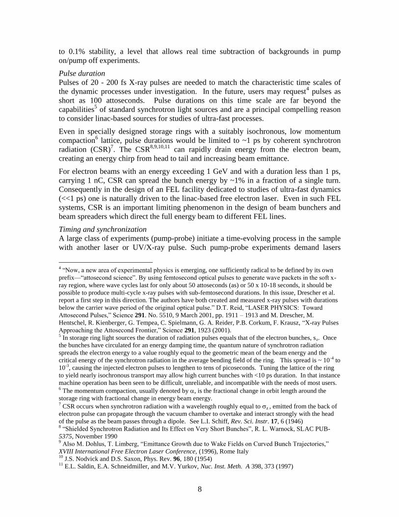
Summary comment
Accompanying the obvious benefits of the enhanced SASE proposals are potentially
important shortcomings or uncertainties. It is not known whether potential degradation
of electron beam quality from unwanted collective effects such as CSR and wakefields in
the accelerator in long undulators will suppress FEL gain. Moreover, both the E-SASE,
“energy-marking” and emittance marking schemes waste ~99.8% of the high-energy
electrons, implying a marked decrease in average photon flux.
III.C Master-Oscillator Power-Amplifier architectures (MOPA)
III.C.1 Basic principles
even
larger class will require that the FEL system furnish the user end station with timing
pulses synchronized to the FEL output to within a fraction of the FEL pulse duration.
Both these requirements can be accomplished with a MOPA architecture.64
Rather than allowing the FEL instability to grow from shot noise, one can inject an initial
radiation signal within the gain-bandwidth of the FEL to co-propagate with the electron
beam through the undulator. If the intensity of the injected signal is much larger than the
shot noise, the output radiation will approximate (in a manner to be described) the
63
Z. Huang and K-J. Kim, “Nonlinear harmonic generation of coherent amplification and self-amplified
spontaneous emission,” Nucl. Inst. and Meth. A 475 (2001) 112–117 64
As the injected signal need not come directly from an oscillator, this architecture is often referred to as a
seeded FEL or in conventional laser parlance, an injection locked amplifier.

28
temporal coherence properties of the input. In this regard, the free electron laser is
different from standard laser amplifiers. In stimulated amplified emission, all the energy
from the population inversion is drained into the (narrower) line width of the injected
master oscillator pulse. Thus the output spectrum is fixed by the input signal. In contrast,
the signal from the FEL grows over the entire gain-bandwidth.
Therefore, when the radiated signal within the line width of the injected signal reaches
saturation, amplified shot noise over the remainder of the gain-bandwidth of the FEL
creates a large spectral pedestal. If this pedestal must be orders of magnitude smaller
than the amplified injected signal, then the intensity of the input signal must exceed the
shot noise by orders of magnitude. In the case of the HGHG schemes described in the
next section, the input signal power65
should be at least 102
and preferably 103
times
larger than the shot noise power.
A complication of using a MOPA or injection-locked architecture is that the electron
beam energy, which sets the central wavelength of the gain-bandwidth, must be stabilized
to well within the gain bandwidth. That is, the energy should be stable on a pulse-to-pulse
basis to ~/3. In a simple amplifier system, this limitation could be circumvented by 1)
having the input laser pulse longer than the electron beam pulse plus 2) imposing an
energy chirp on the electron beam that is greater than the energy jitter of the accelerator.
The price that one pays for this circumvention is that a significant portion of the electron
beam will be wasted and the possibility of precision timing set by the laser master clock
is lost. Finally the MOPA cannot be used directly at wavelengths low which high power
laser operation is possible. Instead some process of harmonic up-conversion must be
employed.
III.C.2. High Gain Harmonic Generation (HGHG) cascades
That the FEL process generates harmonics of the fundamental frequency in the Fourier
components of the electron beam current was recognized early in the development of
FEL systems. The first application of this concept as a path toward frequency up-
conversion66
was in the context of the optical klystron67,68
. Such an experiment69
was
65
Unfortunately for wavelengths less than 20 nm, laser output signals using harmonic generation in gases
are not yet suitable for use as a EUV/X-ray FEL inputs. Progress in this area remains rapid and one can be
optimistic about the availability of tunable master oscillators at 20 – 50 nm within the next several years. 66
See for example, P. Csonka, “Enhancement of synchrotron radiation by beam modulation,” Part. Accel.,
8, 225 (1978). Also N. A. Vinokwov and A. N. Skrinskii, “Oscillator klystron in the optical band using
ultra-relativistic electrons,” Preprint INP 77-59, Novosibirsk, U.S.S.R., 1977; A. N. Skrinsky,
Novosibirsk, Institute Report INP 78-88. See also B. Kincaid et al., “Free Electron Laser Generation of
Extreme UV Radiation,” edited by J. Madey and C. Pelligrini, AIP Conference Proceedings No. 118,
American Institute of Physics, New York (1983) 67
N. A. Vinokurov, in Proceedings of the 10th International Conference on Particle Accelerators,
Serpukhov, 2, p. 454. (1977) 68
The optical klystron is a configuration consisting of two undulators separated by a dispersive section. In
low gain systems that typified early FELs, the beam is modulated in energy in the first undulator by an
injected laser pulse at the frequency of the FEL resonance. The energy-modulated beam then passes
through a dispersive section where the energy modulation is converted into a density modulation. Then
beam then passes into the second undulator (the radiator), which is tuned to either the frequency of the
injected signal or to an harmonic thereof.

29
conducted in 1984 using the ACO storage ring as the beam source. The injected
frequency of the radiation was 1.06 µm from a Nd:YAG laser. The experiment measured
third harmonic radiation (355 nm) from the second undulator at an intensity 100 to 1000
times greater than the spontaneously emitted value.
A fully developed scheme of harmonic multiplication in a multi-stage wiggler was
analyzed by Bonifacio and Scharlemann70
and shortly thereafter extended by Yu71
to the
cascade scheme embodied in the FERMI and BESSY FEL designs The fundamental
concept is simple. The FEL process bunches the beam current into thin slabs, roughly
one-tenth of an optical wavelength long spaced by an optical wavelength. The Fourier
transform of this current distribution contains components (of decreasing magnitude) at
all harmonics of the optical frequency. For this reason the FEL output also contains
radiation72
at harmonics of the resonant frequency.
Passage of a beam exiting the FEL through a second undulator tuned to the harmonics
leads the beam to radiate coherent spontaneous radiation at that harmonic. If the energy
spread in the electron beam is sufficiently small and if the undulator is sufficiently long,
the FEL process can amplify the harmonic signal in the second undulator. The first
practical realization73
of this concept to up-convert an initial seed laser pulse was the
DUV-FEL experiment conducted by Yu and his collaborators at BNL.
For the DUV-FEL experiment, a 300 pC, 4.5 MeV, 4 ps (FWHM) electron bunch from a
1+1/2 cell photocathode gun with normalized emittance of 3–5 π mm-mrad injected into
two S-band SLAC-structures and accelerated to 77 MeV. At this point the bunch was
compressed prior to acceleration to the full energy of 172 MeV. The full energy beam
was co-injected with a 30 MW, 800 nm seed laser pulse into a modulator (undulator)
designed for resonance at 800 nm. Upon exiting the modulator the electron beam entered
a dispersive section to enhance the FEL-induced bunching. Finally the beam traversed
the radiator tuned to the third harmonic of the injected laser signal.
Figure 13 from the DUV-FEL experiment shows the enormous advantages that the
HGHG approach shares will all MOPA realizations of the FEL, namely, the undulator
can be considerably shortened and secondly the spectral width is set by the master
oscillator (seed laser rather than by the gain-bandwidth of the FEL process). The
If the beam current is sufficiently high, the initial radiation could be the shot noise. When placed in a
storage ring, the optical klystron could be surrounded by an optical resonator in either an oscillator or
regenerative amplifier configuration. As the FEL process heats the beam, such a configuration requires that
the synchrotron radiation losses in the remainder of the ring exceed the energy radiated by the FEL or
optical klystron. 69
B. Girard et al., “Optical Frequency Multiplication by an Optical Klystron,” Phys. Rev. Lett. 53, 25,
(1984) 2504 70
R. Bonifacio, L. De Salvo Souza, P. Pierini, E.T. Scharlemann, “Generation of XUV light by resonant
frequency tripling in a two-undulator FEL amplifier,” Nucl. Inst. and Meth. A: 296 (1-3), pp. 787-790 71
L. H. Yu, Phys. Rev A 44, 5178 (1991) 72
This feature of the FEL has been known from the earliest analyses of the FEL process. Due to
interference effects, the radiation from helical undulators does not contain the even harmonics on-axis.
Nonetheless the electron beam current does contain Fourier components at the even harmonics. 73
L. H. Yu et al., Science 289, 932 (2000) and L.H. Yu et al., “First Ultraviolet High-Gain Harmonic-
Generation Free Electron Laser,” Physical Review Letters 91 (7), pp. 748011-748014 (2003). Figure 13
and its caption are reproduced from the latter manuscript.

30
combination of both these considerations mean that the pedestal of radiation outside the
signal line width can be exceedingly small, even without the use of a monochromator.
The concept of the harmonic cascade is that the radiation output from the radiator can
now be used as a high power seed to be injected into a downstream modulator-radiator
section. Both the BESSY-FEL and FERMI @ Elettra have produced designs based on
the principle of harmonic up-conversion of an injected “seed” signal in a single pass, FEL
amplifier employing multiple undulators. The basic principles that underlie this approach
to obtaining short wavelength output are:
a) Energy modulation of the electron beam via the resonant interaction with an
external laser seed in a first undulator (the “modulator”)
b) Passage of the e-beam through a chromatic dispersive section to develop a
strong density modulation with large harmonic overtones;
c) Coherent radiation by the micro-bunched beam in a downstream undulator
(called “radiator”).
Figure 13. “Single shot HGHG spectrum for 30 MW seed power in the DUV-FEL experiment,
exhibiting a 0.1 % FWHM bandwidth. The grey line is the single shot SASE spectrum far from
saturation when the 30 MW seed was removed. The SASE spectrum is the background of the
HGHG output. The average spacing between spikes is used to estimate the pulse length. The
HGHG spectral brightness is 2105 times larger than the SASE undulator is too short to achieve
SASE saturation. Were the undulator doubled in length, the SASE would reach saturation, but
would have an order of magnitude lower spectral brilliance than the HGHG signal.”
An external laser with a beam diameter significantly larger than that of the electron beam
provides the initial wavelength-tunable seed signal. This signal, in conjunction with the
magnetic field generated by the modulator, produces a strong, transversely uniform,
energy modulation of the electrons via resonant interaction. The temporal variation of
the modulation is cwhere is the seed wavelength). When the length of the
modulator is comparable to or shorter than the exponential gain length for FEL radiation
power and when the number of undulator periods obeys the relation 2Nu (/0) < 1, the
modulator produces insignificant accompanying density modulation (i.e., micro-
bunching). The electron beam next passes through a chromatic dispersion section74
in
74
The choice of a dispersion section to bunch the beam (rather than continued passage through the
undulator) minimizes any phase space distortions of the beam outside the region of temporal overlap with
the injected laser pulse.

31
which path length differences associated with the energy modulation produce a density
modulation of the beam. For >> , (the initial “incoherent” slice energy spread), a
strong periodic density modulation is created at wavelength containing large higher
harmonic components (up to harmonic number m~/).
At this point the electron beam enters the radiator, whose wavelength and magnetic
strength are tuned such that the FEL resonance occurs at an integral harmonic m of the
original seed laser wavelength:
lm =l0
m=
lw2g 2
1+ aw2( ) (23)
where aw is the normalized RMS undulator magnetic strength. For FERMI, the harmonic
number, m, varies between 3 and 6 for the first radiator. If this radiator is the final
undulator, it is made sufficiently long for the FEL radiation to grow to saturation (or even
longer via tapering if greater output power is sought).
For a multistage harmonic cascade, the first radiator is generally made much shorter than
that necessary for power saturation. In the so-called “fresh bunch” approach75
(Figure
14), the duration of the electron bunch is several times longer than the duration of the
seed laser pulse. In that case radiation from the first radiator is used to energy-modulate
part of the electron beam in a subsequent modulator; therefore, the first radiator is made
only long enough that the radiation greatly exceeds the shot noise at R and is sufficient
to produce adequate downstream energy modulation. The radiation emitted from the
“radiator” is effectively coherent spontaneous emission, the power of which scales as the
square of the product of the current and the longitudinal distance inside the undulator
(ignoring diffraction and debunching effects).
Following the first radiator is a section (essentially a chicane) that temporally delays the
electron-beam in order to make the output radiation temporally coincident with a “fresh”
section of the electron beam closer to the beam head. This fresh section of the bunch has
not had its incoherent energy spread increased via FEL interaction in the first stage
modulator and radiator. Thus, it can be far more easily energy- and density-modulated in
the second stage undulators than the “used” electron-beam section that interacted with the
seed laser pulse in the first modulator and radiator.
This combination generally leads to a smaller energy modulation at the end of the second
modulator. The second stage radiator is usually much longer than that of the first stage
both because the initial bunching is normally smaller and because the FEL is normally
run to saturation (which requires more distance because the corresponding exponential
gain lengths are longer due to the smaller aw). The process of light emission in the final
radiator includes at first quadratic part (as in the first stage and in single-stage FEL-1
configuration) and then an exponential growth regime. Thus it is similar to the classic
HGHG scheme of Yu.
75
Note that the fresh bunch approach demands the energy jitter of the beam significantly less than

32
(a)
(b)
Figure 14. Schematics of (a) the FERMI HGHG cascade; (b) the fresh bunch approach.
The second stage in the fresh bunch approach consists of a modulator, a final radiator,
and, in general, an intervening dispersive section. The modulator uses the radiation from
the first stage radiator as its seed radiation; it must therefore have its undulator period and
magnetic strength tuned to be resonant at that same wavelength. Since the radiation
diffracts freely once it departs the first radiator, care must be taken 1) that the temporal
delay section is not too long and 2) that the required length of the second modulator does
not exceed the Rayleigh range. Otherwise, the coupling between the radiation and the
electron beam may be too weak for sufficient energy modulation to develop. The second
stage modulator, radiator, and intervening dispersive section are quite similar in concept
to the first stage.
In general, the harmonic upshift factor between the second stage modulator and radiator
is 4 or less (for FERMI). Moreover, the amount of micro-bunching at the new harmonic
in the second radiator is also generally less than half that produced in the first stage
because both the undulator parameter aw and the initial radiation intensity are smaller.
An alternative to the “fresh bunch” scheme in a HGHG cascade is the single-bunch (or
whole bunch) scheme, that has been proposed by Brefeld et al.76
for implementation at
DESY (for FLASH) and that has also been studied extensively in the FERMI technical
optimization study. In the single-bunch approach, the entire beam is energy modulated
by a long laser pulse in the first undulator by an amount smaller than the intrinsic energy
spread in the bunch. Nonetheless, after passage through the dispersive section the density
modulation at the harmonics exceeds the shot noise at these frequencies. Therefore, in
undulator two the FEL radiation signal at the harmonic will have the properties
determined by (thorough not identical with) the initial seed laser.
A potential advantage of the single-bunch approach is that the transform limit of the
radiation can ideally have a narrower line width than is obtainable in the fresh bunch
76
W. Brefeld et al., “Study of the frequency multiplication process in a multistage HGHG FEL,” Nucl. Inst.
and Meth. A 483 (2002) 80–88

33
scheme. A disadvantage is that the time dependent energy variation within the pulse
(chirp) caused by wakefields must be kept flat over a substantially longer pulse.
Brefield at el. also argue that regardless of the particulars of the HGHG, the phase noise
on the beam will grow as m2 where m is the harmonic number of the up-shifted radiation.
As a consequence, the noise power, Pn, of each stage of the cascade will grow by the
square of the frequency multiplication factor. To obtain a good signal-to-noise ratio in
the out put radiation the input laser power, Plaser >> m2Pn imposing a practical limit on the
wavelength that can be reached with a ~200 nm seed laser.
III.C.2.a. Critical design sensitivities for an HGHG user facility
A critical parameter affecting the requisite electron beam duration in an HGHG cascade
is the timing jitter of the beam relative to that of the seed laser. In order to assure
sufficient overlap between the seed pulse and the electrons, the duration of the electron
beam must exceed the sum of the seed pulse duration plus twice the RMS timing jitter.
In the case of FERMI, in which the expected RMS timing jitter from the accelerator is
~150 fs, an e-beam pulse duration >600 fs is needed for 100-fs seed pulses. This timing
jitter is one of the most demanding requirements on the injector and accelerator
subsystems.
Critical to time domain experiments is shot-to-shot repeatability. Ideally, for experiments
probing nonlinear (multi-photon) phenomena, shot-to-shot RMS jitter in normalized
photon number should be 5% or less. Such a low value seems unlikely with S-band
copper accelerators and injectors. The performance is potentially better with a CW
superconducting linac in which feed-forward control is possible. Fortunately a large
class of experiments can tolerate values as high as 25% by recording the shot-by-shot
photon number for post-processing. Other jitter parameters – pointing, virtual waist
location and angular divergence jitter, shot-to-shot transverse profile changes – can
indirectly affect the intensity on the experimental sample. None of these is likely, on an
individual basis, to preclude reaching the goal of 5% (spatially) local intensity
fluctuations at the experimental sample; however, taken together they may produce jitter
exceeding this goal even in the absence of fluctuations in photon number. Notably, some
experiments (e.g., those using gaseous samples) may be insensitive to pointing or profile
changes. Finally, the wavelength jitter should be less than the individual shot bandwidth
so as not to increase the effective time-averaged, output bandwidth as seen by the user.
Intensity control
While in all FEL architectures scaled to short wavelengths, excessive emittance or
incoherent energy spread, E, suppresses gain resulting in low radiated output power, in a
multi-stage harmonic cascade, the sensitivity to energy spread is heightened as the
nonlinear growth of harmonic micro-bunching leads to a sharp cliff in E beyond which
the output radiation in the final stage will be small. Multistage output also displays a
sharp cliff for currents much lower than the design current, because the output power
from the first stage, being coherent spontaneous radiation, scales quadratically with
current. Moreover, if the design of final radiator relies upon strong exponential gain, the
output from that stage will be very sensitive to the beam current.

34
The most sensitive parameter is that of initial electron beam energy. For the MOPA
configuration a fractional change of /3 (0.1% in the case of FERMI) induces large
variations in output power implying stringent shot-to-shot energy jitter requirements.
Such a sensitivity to jitter in electron energy is of utmost concern for those time-domain
experiments measuring nonlinear (multi-photon) phenomena. Figure 15 displays this
sensitivity for FERMI.
The FERMI example is based on a set of calculations done with simultaneous, multi-
parameter jitters (seed power, 5%; energy spread, 10%; peak current, 8%, emittance
10%); a set of 400 parameter values were created in which each and every beam
parameter was randomly varied following the appropriate Gaussian distribution. The
single parameter sensitivity scan (line) shows that energy plays a crucial role in the FEL
performance of a seeded HGHG system. The multi-parameter results (dots), remain very
well correlated to the electron energy variation, although they show scatter due to the
other parameters being varied.
Figure 15. FERMI FEL output power at 40 nm as a function of electron-beam energy in the case
of a single parameter only (curve) and multi-parameter (dots) variation.
Spectral control
For frequency domain experiments, shot-to-shot repeatability in photon number is of less
concern than preserving central wavelength and the narrow spectral bandwidth of the
seed radiation. In an HGHG cascade, the chromatic dispersion sections that produce
strong micro-bunching before each radiator also introduce a strong sensitivity of output
wavelength to initial energy chirp on the electron beam. In particular, a temporally
broad, quadratic chirp in energy leads to a linear chirp in output wavelength making it
difficult to reach the transform limit, even when the magnitude of the dispersive matrix
element of the transport matrix of the bunching chicanes is made as small as practical.
However, this effect is essentially deterministic and does not dilute the longitudinal phase
space of the radiation on a microscopic level.
Narrow temporal fluctuations in electron beam energy (such as might develop from the
micro-bunching instability) also will broaden the spectral band pass77
and, if severe
enough, actually dilute the microscopic phase space of the radiation. The combination of
statistically varying energy chirp on the electron pulse and the use of bunching chicanes
also leads to pulse-to-pulse jitter in the central frequency of the FEL that is not seen in
77
A chirp in the frequency of the injected laser pulse can also broaden the line width.

35
simple MOPA configurations. This effect is illustrated in the calculations of Figure 16
for the FERMI FEL operating at 40 nm.
For experiments such as resonant inelastic X-ray scattering (RIXS) that probe a small,
inelastic scattering cross-section in the presence of a much larger elastic scattering cross-
section, the requisite spectral resolution of 105 requires that the integrated noise photon
level outside the central radiation line width be less than 1 part in 105 of the desired
signal at the detector. Without spectral filtering using a monochromator, this requirement
could be more stressing than that of RMS bandwidth. For example, if the integrated noise
power is 1 part in 104 but has a bandwidth 100 times greater than the main signal, the
total (signal + noise) RMS bandwidth increases by only ~40% from that of the signal, but
the unfiltered spectral resolution would still miss the 105 criterion by a factor of ten.
Figure 16. Jitter in the central frequency of the output from the FERMI FEL operating at 40 nm.
III.C.2.b HHG seeded cascades
Presently the limit to which harmonic up-conversion is practical in HGHG arrays is not
experimentally established. In the FERMI FELs a design factor of 10 – 15 is
contemplated in two stages; the 2.3 GeV BESSY design contemplates a factor of ~200 in
four stages. Simulation studies78
in both projects indicate that the quality of the output
radiation decreases as the number of cascade stages increases. An alternative is to replace
the first HGHG stage with a gas cell that up-shifts the injected laser pulse via the process
of high harmonic generation (HHG).
The HHG process79
results from focusing a pump laser into a gas to such a power density
that the optical field at the interaction point is comparable to the internal atomic field.
Ionization tunneling, acceleration, and subsequent recombination of electrons result in
bursts of radiation every half cycle of the optical radiation. A sample spectrum of the
radiation from Ne is shown in Figure 1780
.
78
For example see E.L. Saldin, E.A. Schneidmiller, M.V. Yurkov, “Study of a noise degradation of
amplification process in a multistage HGHG FEL,” (2002) Optics Comm., 202 (1-3), pp. 169-187. The
authors conclude that, “The results presented in this paper have demonstrated that the HGHG FEL
approach is quite adequate for a 10–100 nm coherent source, but not scalable to an X-ray device.” 79
For a quasi-classical interpretation of the process see P.B. Corkum, Phys. Rev. Lett. 71 (1993) 1994.
Also see M. Lewenstein, et al., Phys. Rev. A 49 (1994) 2117. 80
D. Garzella, T. Hara, B. Carre’, P. Salieres, T. Shintake, H. Kitamura, M.E. Couprie, “Using VUV high-
order harmonics generated in gas as a seed for single pass FEL,” Nucl. Inst. and Meth. A 528 (2004) 502–
505

36
Figure 17. HHG spectrum of Ne from the 35
th to 59
th harmonic
III.C.3 Hardware tolerances in short wavelength FELs
All short wavelength FELs place tight tolerances on maintaining a precise alignment of
the electron trajectory with the central axis of the undulator. In addition to errors in
launching the e-beam into the undulator (offset, tilt, and mismatch), other errors are
possible within the undulator. These include: 1) tilt and offsets of entire undulator
segments, 2) “global” segment mistuning errors such that the average aw is offset by a
constant amount within each segment (e.g. due to an incorrect gap setting), 3) “local”
undulator errors due to errors in the strength of individual pole pieces. Local errors can
lead both to longitudinal phase errors between the electron beam and the FEL radiation
and to the electron beam wandering away from both the central axis of undulator and the
radiation.
To lowest order, tilt and offset of the undulator are equivalent to errors (equal and
opposite in value) in the initial electron beam position and tilt. In multi-segment
undulators, the effect of these errors could, in a statistical sense, grow as N where N is
the number of segments. Hence, if a criterion for beam tilt and offset is a value Y, then
the equivalent RMS criterion for the individual segments might need to be reduced to
Y/N. However, with active dipole correctors between segments, this estimate may be
unduly pessimistic. The technological aspects of alignment tolerances are discussed
briefly in section IV.E. 2.
“Global” mistuning of segments leads to an error in longitudinal phase that grows with
distance as the beam traverses the undulator. As the phase error approaches /2 radians,
FEL gain is suppressed. A rough criterion for the RMS accuracy of setting aw
(equivalently the gap opening) in the final radiator can be established by performing a
series of computer simulations in which random tuning errors with a given RMS
expectation value are applied to each individual radiator segment. An example for
FERMI at an output wavelength of 40-nm, is shown in Figure 18. The calculations show
that in an average sense, the RMS segment mistuning error in aw must exceed 0.002
before the output power begins to drop more than a few percent. This constraint appears
be relatively easy to meet for the FERMI undulators.

37
Figure 18. Output radiation power at 40-nm from FEL-1 of FERMI produced by random
undulator segment mistuning as a function of RMS error in aw. The diamond symbol and
error bars refer to the mean and standard deviation over 64 independent mistunings. The
distribution of errors at individual segments follows a one-dimensional Gaussian.
III.D. Cavity FELs
In an FEL oscillator the undulator is located within an optical cavity resonator as shown
in Figure 1981
. The configuration oscillator requires that electron beam pulses pass
through the resonator at a rate set by the round trip time of the photons in the cavity. The
multi-MHz rates thus implied naturally suggest the possibility of placing the FEL within
a storage ring82
. In third generation storage rings, a typical peak current per bunch is of
order 10 A. For 2 GeV operation, consistent with a FEL operating at 10 nm, and a mean
normalized emittance of ~3 π mm-mrad, the gain length would be ~50 m. Therefore a
10 m insertion undulator would have a gain of ~ 1.2. For a resonator with only two
mirrors, the mirror reflectivity, R, would have to exceed 0.9 for net gain in the resonator.
Unfortunately such high reflectivity is not obtainable at present, but they are sufficiently
high83
to offer an alternative approach to driving the FEL.
In linac driven FELs the limitations on peak current and beam emittance imposed by the
storage ring can be avoided. With peak currents raised to ~100 A and emittance
improved to ~2 π mm-mrad, the gain length can be reduced by a factor of ten. Thus even
in a four mirror resonator, a 10 m undulator can produce an overall gain of 20 –30%.
This fact is the basis for the multi-pass, self-seeded Regenerative Amplifier FEL
(RAFEL) proposed and tested at infra-red wavelengths by Nguyen et al.84
at Los Alamos.
In the RAFEL the initial signal is not injected but rather grows from noise and is
81
Adapted from a presentation by H. Padmore, private communication (2006) 82
This approach has been implemented in Elettra within the EUFELE project, but with a resonance
condition limited to an electron energy of about 1 GeV, and a lower limit of the wavelength of about 150
nm, due to the limits in reflectivity of the available materials. 83
At 11 nm normal incidence reflectivities of ~70% have been measured in a 50 period Mo-Be multi-layer
optic, S. Bajt, J. Vac. SciTechnol. 18(2) (2000), pp 557 –559 and P. B. Mirkarimi, S. Bajt, and M. A. Wall,
"Mo Si and Mo Be Multilayer Thin Films on Zerodur Substrates for Extreme-Ultraviolet Lithography,"
Appl. Opt. 39, 1617-1625 (2000) 84
D. C. Nguyen, L. M. Earley, N. A. Ebrahim, C. M. Fortgang, J. C. Goldstein, R. F. Harrison, W. A.
Reass, J. M. Kinross-Wright, R. L. Sheffield, and S. K. Volz, “Regenerative Amplifier FEL,” Proc. XX
International Linac Conference, Monterey, California (2000)

38
amplified by the SASE process. Unlike an oscillator, the RAFEL does not store and
build optical energy in the cavity to be switched out after the system reaches saturation.
Instead the low-Q optical cavity serves to re-inject a small fraction of the optical power
into a high-gain undulator as the seed for the next pass. In the Los Alamos experiment,
the low-Q optical cavity was a simple ring resonator consisting of two imaging
paraboloids and two annular mirrors that out-couple ~50 % of the generated radiation
allowing the RAFEL to come to saturation after few passes through the undulator.
Figure 19. Simplified schematic of a cavity FEL
The RAFEL architecture is ideally suited to be driven by an energy recovery linac and
has been adopted for the design85
of the VUV-FEL (3 – 10 eV) at 4GLS. An advantage
of the RAFEL with respect to SASE is that the system smoothes out the shot noise over
many passes, thereby considerably reducing the spiky behavior seen in pure SASE FELs.
The baseline 4GLS design has three 2.2 m undulator sections yielding a gain of gain ~4
for 300 A operation. At such a high gain the FEL is relatively insensitive to the mirror
reflectivity.
Critical issues for this architecture, especially pushing the design into the soft X-ray
regime, are appropriate cooling of the mirrors for high average power operation and the
damage of the mirrors by FEL radiation at the higher harmonics.
III.E. Attosecond FELs
Zholents and Fawley have proposed86
an FEL architecture for producing isolated pulses
of soft X-rays with a duration of ~100 attoseconds using electrons selected by their
previous interaction with an intense, few-cycle, laser pulse. The authors call this process
seeded attosecond x-ray radiation (SAXR).’’ In principle, SAXR allows excellent
temporal synchronization between the attosecond x-ray probe pulse and a pump source
that could be the same few-cycle pulse or another laser signal derived from it.
Consequently, it is conceivable to track the temporal evolution of atomic or molecular
states during a single optical cycle in the process of laser-assisted photo-ionization.
As a specific example they choose 2 nm as the x-ray source wavelength with which to
generate 1-nm wavelength, attosecond radiation. As long as an intense, coherent source
85
N. R. Thompson, M. W. Poole, B. W. J. McNeil, “A VUV-FEL for 4GLS: Design Concept and
Simulation Results,” Proc. International FEL Conference, Stanford, California, (2005) 86
Alexander A. Zholents and William M. Fawley , “Proposal for Intense Attosecond Radiation from an X-
Ray Free-Electron Laser,” Phys. Rev. Lett.., V. 92, Number 22, 4 June 2004. Figures 20 and 21 are
reproduced from this manuscript.

39
is available, attosecond pulse generation at both longer and shorter wavelengths would
also be possible with the same scheme.
As illustrated schematically in Figure 20, SAXR requires the combination of an ultra-
relativistic electron beam, a few-cycle, intense optical laser pulse and an intense pulse of
coherent x-ray radiation, together with a number of magnetic undulators and transport
elements. On the left is a source of 100-fs, 100-MW peak power, x-ray pulses. That
source could, for example, be an harmonic cascade FEL (HC FEL) configured such that
the trailing portion of a sufficiently long (~2 ps) electron bunch is used for the initial x-
ray generation. Recall that the fresh-bunch configuration prevents the portion of the
beam near the bunch head from having its instantaneous energy spread degraded either
by previous FEL interactions in the upstream cascade or even by SASE gain.
Figure 20. A schematic of the components involved in attosecond x-ray pulse production
An achromatic bend downstream of the HC FEL directs the electron beam into a two-
period, undulator magnet (‘‘800-nm modulator’’) where it co-propagates in resonance
with an 800-nm wavelength, ~1-mJ, 5-fs laser pulse that temporally overlaps only the
undisturbed portion (fresh-bunch) of the beam. The 800-nm modulator imprints a time-
dependent electron energy modulation such as shown in Figure 10a. All pulses are
tightly synchronized with the original master oscillator pulse of the HC FEL.
A second isochronous bend after the 2-period undulator returns the electrons back to its
original axis, while the 800-nm laser pulse continues to propagate along a parallel, offset
path. Next, the electrons enter a long undulator modulator (UM) resonant at a 2-nm
wavelength. The coherent, 100-fs long, 2-nm output pulse from the HC FEL arrives
simultaneously with those electrons that experienced the strong energy modulation at 800
nm and both co-propagate through UM. The undulator parameter aw of the UM is tuned
such that only those electrons very near the peak of the 800-nm energy modulation have
the correct energy for resonant FEL interaction with the 2-nm X-rays. As all other
electrons fall outside the energy bandwidth of the UM FEL, they are not significantly
modulated. By making UM slightly shorter (Lu ~ 5 m) than one full FEL gain length, one
assures that there is little SASE action that would produce unwanted micro-bunching at
the 2-nm wavelength throughout the entire 2-ps long electron bunch).
Downstream of UM another isochronous chicane enhances the bunching of sub-
femtosecond portion of the bunch that has been modulated at 1 nm. The chicane also
allows the diversion of the 2 nm X-rays from the attosecond beamline. After passing
through the chicane the electrons enter a long radiator resonant at 1 nm. The result,
shown in Figure 21, is a multi-GW pulse of 1 nm X-rays with a duration of 110
attoseconds.
40
Figure 19. The sub-femtosecond, 1nm output from the Fawley-Zholents architecture
Related schemes of producing sub-femtosecond pulses have been proposed87
using
energy chirped beams. While the authors have claimed the possibility of using optical
elements to reduce the pulse duration to 10 attoseconds, no analysis of dispersion in such
elements is presented. Given the very large intrinsic bandwidth of such short pulses any
beamline would have to be achromatic to at least third order. Moreover the optical
elements of such a beam transport would likely need a spatial uniformity at the level of 1
nm to avoid dispersive effects.
III.F. Circumventing limitations on the FEL process
As was discussed in Section III.A.2, excessive energy spread and excessive emittance can
severely suppress FEL gain. In 1992 Sessler, Whittum and Yu proposed88
circumventing
these limitations by tailoring the distribution of transverse and longitudinal velocities in
the beam. Since that time several investigators have proposed methods including rf-
cavities89
, Thompson scattering90
, and laser manipulation91
to achieve this tailoring (or
conditioning) with varying degrees of practicality. The conditioning process involves
introducing a correlation between the total electron energy and the transverse random
transverse motion of particles.
Emma and Stupakov have cautioned92
that, in many such schemes, conditioning a
nonzero length beam by introducing the correct correlation between betatron amplitude
and particle energy leads to betatron mismatches at different longitudinal positions along
the bunch that result in an effective increase in the transverse emittance. This difficulty is
87
E.L. Saldin, E.A. Schneidmiller, and M.V. Yurkov, “Attosecond Pulses from X-Ray FEL with an
Energy-Chirped Electron Beam and a Tapered Undulator,” Proceedings of FEL 2006, BESSY, Berlin,
Germany 88
A.M. Sessler, D. H. Whittum, and L.-H. Yu, Phys. Rev. Lett. 68, 309 (1992). 89
N.A. Vinokurov, “Multisegment undulators for short wavelength FEL,” Nucl. Inst. and Meth., 375, Pp
264-268, (1996) 90
C.B. Schroeder, E. Esarey, W. P. Leemans, W.P., “Electron-beam conditioning by Thomson scattering,”
Physical Review Letters 93 (19), pp. 194801-1-194801-4 91
A.A. Zholents, “Laser assisted electron beam conditioning for free electron lasers,” Phys. Rev. ST Accel.
Beams 8, 050701 (2005). Figures 23 and 24 are reproduced from this manuscript. 92
P. Emma and G. Stupakov, Phys. Rev. ST Accel. Beams 6, 030701 (2002).

41
avoidable93
, but it does constrain the acceptable conditioning processes. Assuming that
practical difficulties can be overcome, one could realize benefits as dramatic as displayed
in Figure 22 for a soft X-ray FEL (2.5 GeV, 0.5 kA) operating at 1 nm.
Figure 22. Effect of emittance conditioning on the radiation power as a function
of undulator length in a 1nm FEL. The calculations assume that all electrons in
the beam are conditioned.
The laser-conditioning scheme proposed by Zholents (Figure 23) extends the rf-
conditioning approach concept introduced by Vinokurov to optical wavelengths. It
displays a further, practical limitation on conditioning proposals, i.e., introducing proper
correlations in some of the beam comes at the expense of spoiling the effective emittance
of other portions (Figure 24). In the Zholents-Vinokurov schemes only half the electrons
are properly conditioned; the remainder of the beam suffers an increase in the spread of
transverse velocity resulting in little gain for these portions. The optical scheme has a
second practical difficulty: timing in the beam-laser interaction in the second undulator
must be controlled to a small fraction of an optical wavelength.
Figure 23. The laser conditioning scheme of Zholents is derived from the Vinokurov scheme.
While experiments have been proposed to demonstrate the predicted benefits of beam
conditioning, this exciting prospect awaits a definitive test.
93
A.Wolski, G. Penn, A. Sessler, and J.Wurtele, “Beam conditioning for free electron lasers: Consequences
and methods,” Phys. Rev. ST Accel. Beams, 7, 080701 (2004). Figure 22 is reproduced from their
manuscript.

42
Figure 24. A distribution of the electron longitudinal velocities (1011) for
unconditioned (a) and conditioned (b) electron beams. The uncorrelated energy
spread of the particles is ignored.