pro 2 - two wire controller - hit products corp · pro 2 - two wire controller two wire irrigation...
TRANSCRIPT

PRO 2 - Two Wire ControllerPRO 2 - Two Wire Controller
Two Wire Irrigation ControllerInstallation and Operating Instructions
Manufactured by Hit Products Lindsay, CA USA


WWW.RAINPROCO.COM PRO 2 �
TABLE OF CONTENTS TABLE OF CONTENTS TABLE OF CONTENTS
Topic Page
Specifications.......................................................................... 2
Installation Do’s & Don’ts....................................................... 5
Installing the PRO 2...............................................................Installing the PRO 2............................................................... 6
Diagram Power Connection....................................................Diagram Power Connection.................................................... 7
Diagram Field Wiring..............................................................Diagram Field Wiring.............................................................. 8
Diagram Valve Wiring.............................................................Diagram Valve Wiring............................................................. 9
Diagram Rain Sensor..............................................................Diagram Rain Sensor.............................................................. �0
Programming the PRO 2........................................................Programming the PRO 2........................................................ ��
Decoder Programming...........................................................Decoder Programming........................................................... �7
Diamond Setting.....................................................................Diamond Setting..................................................................... 20
Two Wire Operation................................................................ 22
Troubleshooting Hints............................................................ 23

WWW.RAINPROCO.COM2 PRO 2 WWW.RAINPROCO.COM
SPECIFICATIONSSPECIFICATIONS
FEATURES PRO 2
Stations Available 1-16
Programs Available 6
Run Time Per Station (In min and/or hrs.)Programs 1-5
0-10 hours, 59 min. Max.0-27 hours-use 250% budget0-27 hours-use 250% budget
Run Time Per Station (In sec and /or min.)Run Time Per Station (In sec and /or min.)Program 6
0-59 min., 59 sec.0-2 hours 30 min.-use 250% budget0-2 hours 30 min.-use 250% budget
Calendar 0-28 days Max., Weekly, Odd/Even0-28 days Max., Weekly, Odd/Even
Irrigation Water Budget by ProgramIrrigation Water Budget by Program 0-250%
Programmable Rain OFF Days Programmable Rain OFF Days 0-31 days Max.
Pause - Between Stations 0-59 sec.
Programs Running SimultaneouslyPrograms Running Simultaneously 2
Maximum ValvesRunning Simultaneously
2 Plus Master Valve or Pump Start2 Plus Master Valve or Pump Start2 Plus Master Valve or Pump Start2 Plus Master Valve or Pump Start
Valves Per Decoder 1
Master ValvePump Start
Yes using Programmed Pro 2 DecodersYes using Programmed Pro 2 DecodersYes
Rain Sensor Capable Yes
Field Wire Outputs 1, wire path may be branched and teed as 1, wire path may be branched and teed as necessary.
Minimum Wire Size 18 gauge
Maximum Wire Run 2,000’
Maximum Number ofDecoders on system
25
DecodersProgrammable andRe-Programmable to desired valve number
Yes
On Board DecoderProgrammingCapability at Controller
Yes
Remote DecoderProgramminguse LP-HHRP
Yes

WWW.RAINPROCO.COM WWW.RAINPROCO.COM PRO 2 3
Input Power:Input Power:100-230VAC 50/60Hz100-230VAC 50/60Hz
Controller Surge Protection:Surge protection is provided by circuit board components, and connection to a Ground-ing Rod. Rod is customer supplied.
Field Surge Protection:Is provided by the use of LP-SPD-F devices. Designed to be installed in valve boxes every 200-300 feet or as needed and attached to a Grounding Rod. Grounding Rod is customer supplied.
Field Wiring:
Wire type: Single strand direct burial, Jacketed two conductor, orSingle strand direct burial, Jacketed two conductor, or Stranded.Stranded.
Wire Size: Minimum 18 gauge Minimum 18 gauge
Wire Runs: Maximum 2000’ Maximum 2000’
Branching &Teeing: Teeing: T Yes
DO NOT “Loop” DO NOT “Loop” the field wires back to the controller OR back onto themselves.the field wires back to the controller OR back onto themselves.DO NOT splice and direct buryDO NOT splice and direct buryDO NOT splice and direct buryDO NOT splice and direct bury wire connections/splices. All wire connections/splices wire connections/splices. All wire connections/splices should be made in valve boxes.should be made in valve boxes.
Maximum Valve Operation:Maximum Valve Operation:A maximum of 2 valves, any where on the system, may operate simultaneously, of either A maximum of 2 valves, any where on the system, may operate simultaneously, of either same number or combinations of different numbers. The 2 valve maximum does not same number or combinations of different numbers. The 2 valve maximum does not include the Master valve or Pump Start Relay. Controller specifications are based on include the Master valve or Pump Start Relay. Controller specifications are based on a Standard 24VAC irrigation valve solenoid rated with a maximum 350 mA inrush and a Standard 24VAC irrigation valve solenoid rated with a maximum 350 mA inrush and a maximum 250 mA holding current at 24VAC. Controller is not compatible with Low a maximum 250 mA holding current at 24VAC. Controller is not compatible with Low Power / Diode Bridge solenoids.
Wire Connectors:One of the most critical installation requirements of a PRO 2 two wire system is the quality of your wire connections. If you follow these directions you will have a reliable, dependable control system for many years. It is suggested to solder all decoder (red wire) connections to your main two-wire run. Install the soldered two-wire connection in a waterproof underground connector housing. When soldering is impractical, a water-proof “dry-type” Hit Products DBC-BR wire connector is required. The above mentioned product will provide an uncontaminated, reliable dry connection. A DBC-BR Kit (1 each) is included with each Pro 2 Decoder.
Do not use pre-filled wire nut connectors as they will impede the transfer of the Do not use pre-filled wire nut connectors as they will impede the transfer of the signal through the wire splice.signal through the wire splice.

WWW.RAINPROCO.COM� PRO 2 WWW.RAINPROCO.COM
Pump Start RelayPump Start RelayWhen using a pump start relay, the relay shall be a 24 VAC coil with a maximum inrush When using a pump start relay, the relay shall be a 24 VAC coil with a maximum inrush When using a pump start relay, the relay shall be a 24 VAC coil with a maximum inrush current of .35 amps and a maximum holding current of .25 amps. The relay will act as a slave to the magnetic relay to control the pump motor. You can use up to a 5hp Hit Products pump start relay (24 VAC at .35 amp in rush and .25 amp holding) attached to a M.V. / P.S. Decoder off of the field Two Wire path.
Rain SensorThe Rain Sensor terminal is located on the bottom center of the Controller board labeled “RAIN OFF.” Note: Use only Rain Switches with normally closed “Dry Contacts” (No “RAIN OFF.” Note: Use only Rain Switches with normally closed “Dry Contacts” (No Power). See Rain Sensor on page 12 of Programming Instructions for more information. See Rain Sensor on page 12 of Programming Instructions for more information.
Multiple Controller InstallationMultiple Controller InstallationInstall a separate Grounding Rod for each controller. Do not connect the field wires of Install a separate Grounding Rod for each controller. Do not connect the field wires of one controller with those of another. Use slave or isolation relays if activating a common one controller with those of another. Use slave or isolation relays if activating a common master valve or pump start relay. master valve or pump start relay.
Power ONThere is a 5 second countdown / delay to “Power ON” the system on initial start up of any There is a 5 second countdown / delay to “Power ON” the system on initial start up of any manual or automatic watering activity. This eliminates the need to have the system “Hot” manual or automatic watering activity. This eliminates the need to have the system “Hot” with voltage at all times.
Accessory:Hand held programmer. For remotely Programming Decoders in the field or office. Hand held programmer. For remotely Programming Decoders in the field or office. Part Number LP-HHRP
Warranty: Any Decoder returned for warranty must have the DBC-BR connection Warranty: Any Decoder returned for warranty must have the DBC-BR connection Warranty: Any Decoder returned for warranty must have the DBC-BR connection Warranty: Any Decoder returned for warranty must have the DBC-BR connection attached. If the DBC-BR is unattached, warranty is void.attached. If the DBC-BR is unattached, warranty is void.attached. If the DBC-BR is unattached, warranty is void.attached. If the DBC-BR is unattached, warranty is void.

WWW.RAINPROCO.COM WWW.RAINPROCO.COM PRO 2 5
PRO 2 Installation “Do’s & Don’ts”PRO 2 Installation “Do’s & Don’ts”PRO 2 Installation “Do’s & Don’ts”
For Warranty To Be Valid, Installation Must Comply To All Instructions Below
1. Use only PRO2-D Decoders the (Black Molded PRO 2 Box) with the PRO 2 Controller.
2. Branching and Teeing of field Two Wire path is permitted with the PRO 2 Controller System. Wire splices should be well planned and minimized with care given using only System. Wire splices should be well planned and minimized with care given using only waterproof DBC-BR splice kits. All wire connection splices are to be made in a valve box. waterproof DBC-BR splice kits. All wire connection splices are to be made in a valve box. DO NOT bury any connection/splices.DO NOT bury any connection/splices.
3. PRO 2 Decoders must be directly attached to the 2 wire path; red wires to field wires, 3. PRO 2 Decoders must be directly attached to the 2 wire path; red wires to field wires, black wires to solenoid.
4. Wire Connections
A. All field wiring Connections of PRO 2 Decoder Red Wires (1 each to each of All field wiring Connections of PRO 2 Decoder Red Wires (1 each to each of field wires) to the field wires must use the enclosed DBC-BR splice kits. field wires) to the field wires must use the enclosed DBC-BR splice kits. See instructions on back. DO NOT USE PRE-FILLED GEL TYPE WIRE NUTS.See instructions on back. DO NOT USE PRE-FILLED GEL TYPE WIRE NUTS.
B. All Decoder to Valve Solenoid Connections must be waterproof, using “dry All Decoder to Valve Solenoid Connections must be waterproof, using “dry type” wire connectors (Hit Products DBC series or 3M™ DBY/DBR series™) and/type” wire connectors (Hit Products DBC series or 3M™ DBY/DBR series™) and/ type” wire connectors (Hit Products DBC series or 3M™ DBY/DBR series™) and/ type” wire connectors (Hit Products DBC series or 3M™ DBY/DBR series™) and/or soldered and then installed in waterproof housings. DO NOT USE PRE-or soldered and then installed in waterproof housings. DO NOT USE PRE- FILLED GEL TYPE WIRE NUTS.FILLED GEL TYPE WIRE NUTS.
5. DO NOT install the PRO 2 Controller, its Decoder or any PRO 2 Field Wire within 15 5. DO NOT install the PRO 2 Controller, its Decoder or any PRO 2 Field Wire within 15 feet of any high voltage electrical panels, meters, pumps, equipment or controls.feet of any high voltage electrical panels, meters, pumps, equipment or controls.
6. Use with standard 24 VAC solenoids only. DO NOT use any with low power/diode 6. Use with standard 24 VAC solenoids only. DO NOT use any with low power/diode bridge type solenoids.
7. On multiple controller Installations DO NOT connect any field wires of onecontroller with those of another. Each controller must have a separate Grounding Rod.
8. DO NOT “loop” field wiring. Terminate the field wires at the last valve on that 2 wire path.
This is a computer, install it accordingly and it will serve you well. If you have any ques-tions, please don’t hesitate to call the factory in California (800) 468-0071, ext. 115 for help. 8am-5pm, Mon-Fri.

WWW.RAINPROCO.COM6 PRO 2 WWW.RAINPROCO.COM
INSTALLING THE PRO 2INSTALLING THE PRO 2Mounting the controller...........When selecting the controller installation location, Mounting the controller...........When selecting the controller installation location, Mounting the controller...........When selecting the controller installation location, make make sure controller and all related wiring is a minimum of 15 feet from any high voltage sure controller and all related wiring is a minimum of 15 feet from any high voltage sure controller and all related wiring is a minimum of 15 feet from any high voltage sure controller and all related wiring is a minimum of 15 feet from any high voltage control boxes, pumps or any high voltage equipment. This irrigation controller is control boxes, pumps or any high voltage equipment. This irrigation controller is a computer and should be installed accordingly.a computer and should be installed accordingly.When mounting the PRO 2 indoors, notice the “keyhole” shaped mounting slot as well When mounting the PRO 2 indoors, notice the “keyhole” shaped mounting slot as well as 2 mounting holes on the back of the controller. Use the template provided to locate mounting screw location. To attach to wall studs, use a #8 screw, leaving 1/4” of the shank exposed to slip into the “keyhole” slot.When mounting the PRO 2 outdoors, use the same procedure as above. When attachWhen mounting the PRO 2 outdoors, use the same procedure as above. When attach-ing the controller to hollow walls, masonry, or cinder blocks, use appropriate toggle bolts, ing the controller to hollow walls, masonry, or cinder blocks, use appropriate toggle bolts, masonry shields or compression drive bolts. For additional weatherproofing, run a silicon masonry shields or compression drive bolts. For additional weatherproofing, run a silicon bead around the case between the controller and the wall. It is also recommended to fill bead around the case between the controller and the wall. It is also recommended to fill mounting holes with silicon as well, to prevent water or insects from entering the controlmounting holes with silicon as well, to prevent water or insects from entering the control-ler.Please read the entire operational manual before installing and programming the Please read the entire operational manual before installing and programming the Please read the entire operational manual before installing and programming the Please read the entire operational manual before installing and programming the PRO 2 Controller.
PROGRAMMING THE PRO 2 ControllerPROGRAMMING THE PRO 2 ControllerThe PRO 2 Controllers are so easy to program because the four sets of blue up/down The PRO 2 Controllers are so easy to program because the four sets of blue up/down arrow buttons correspond to whatever is directly above them in the display. You can arrow buttons correspond to whatever is directly above them in the display. You can toggle between ON and OFF, set hours, minutes, and seconds, or even select program toggle between ON and OFF, set hours, minutes, and seconds, or even select program numbers, valve numbers, and start times simply by using these up/down buttons located numbers, valve numbers, and start times simply by using these up/down buttons located directly under their functions.directly under their functions.
Each set (two buttons) of buttons operates the display up or down for ease of getting to Each set (two buttons) of buttons operates the display up or down for ease of getting to the function, number, valve or time desired. For ease of explanation, the following termithe function, number, valve or time desired. For ease of explanation, the following termi-nology will be used throughout these instructions. The set of buttons to the far left will be nology will be used throughout these instructions. The set of buttons to the far left will be button set 1, directly right of these will be , directly right of these will be set 2, directly right of , directly right of set 2 will be set 3 and the last set or far right set will be the last set or far right set will be set 4. The main rotary dial has 12 positions just like . The main rotary dial has 12 positions just like the numbered hour positions on a clock 1-12. The rotary switch consists of the following the numbered hour positions on a clock 1-12. The rotary switch consists of the following positions and functions:
NOTE:With a new installation be sure to do a “Master Clear” before programming. Rotate the Dial to position 10. Using the set 4 arrow buttons press the up arrow button under “CLR/OFF” on the Display. The Display will change. Press the same arrow button, under the word “Yes” again. The display will prompt you to. “Please Wait”. When the display changes. Rotate the Dial to start programming.

WWW.RAINPROCO.COM WWW.RAINPROCO.COM PRO 2 7
PowerAdapter
• AC Power In
POWER CONNECTION

WWW.RAINPROCO.COM8 PRO 2 WWW.RAINPROCO.COM
Valve Valve Valve Valve ValveValve
Valve
• Branch or Tee
• Branch or Tee
FIELD WIRING
• Ground Rod
WWW.RAINPROCO.COM WWW.RAINPROCO.COM PRO 2 9
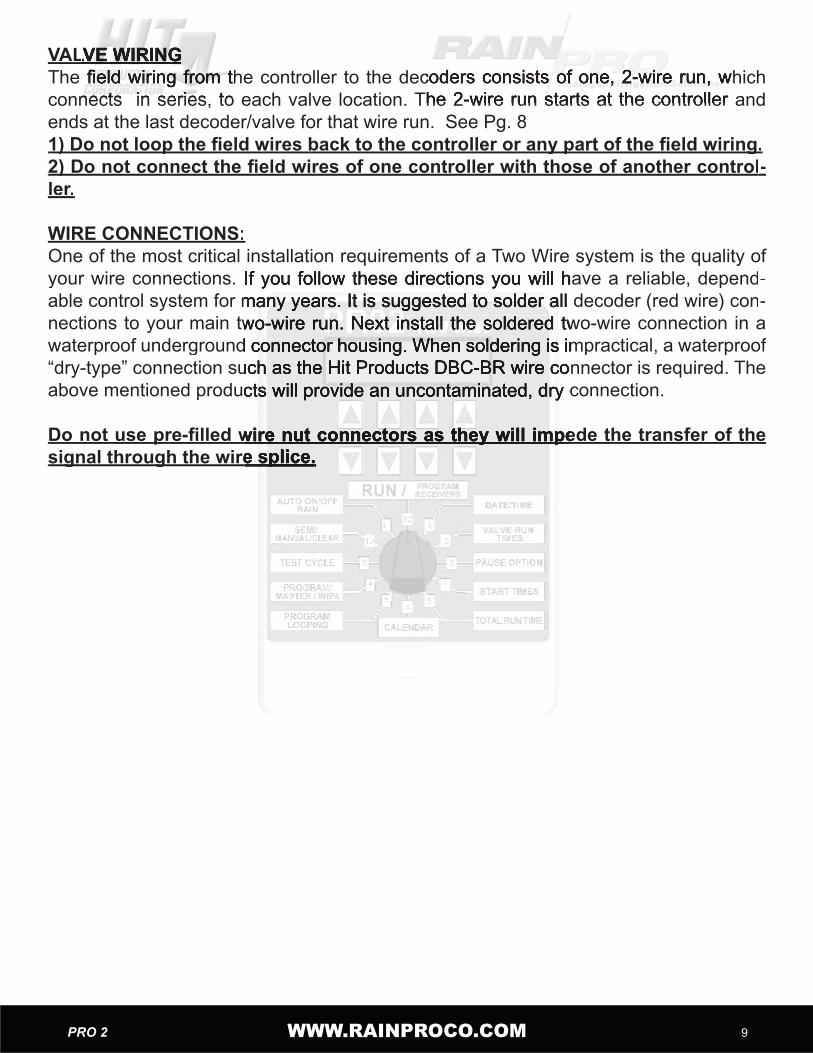
VALVE WIRINGVALVE WIRINGThe field wiring from the controller to the decoders consists of one, 2-wire run, which The field wiring from the controller to the decoders consists of one, 2-wire run, which The field wiring from the controller to the decoders consists of one, 2-wire run, which connects in series, to each valve location. The 2-wire run starts at the controller and connects in series, to each valve location. The 2-wire run starts at the controller and connects in series, to each valve location. The 2-wire run starts at the controller and ends at the last decoder/valve for that wire run. See Pg. 81) Do not loop the field wires back to the controller or any part of the field wiring.1) Do not loop the field wires back to the controller or any part of the field wiring.2) Do not connect the field wires of one controller with those of another control2) Do not connect the field wires of one controller with those of another control-ler.
WIRE CONNECTIONS:One of the most critical installation requirements of a Two Wire system is the quality of your wire connections. If you follow these directions you will have a reliable, dependyour wire connections. If you follow these directions you will have a reliable, depend-able control system for many years. It is suggested to solder all decoder (red wire) conable control system for many years. It is suggested to solder all decoder (red wire) con-nections to your main two-wire run. Next install the soldered two-wire connection in a nections to your main two-wire run. Next install the soldered two-wire connection in a waterproof underground connector housing. When soldering is impractical, a waterproof waterproof underground connector housing. When soldering is impractical, a waterproof “dry-type” connection such as the Hit Products DBC-BR wire connector is required. The “dry-type” connection such as the Hit Products DBC-BR wire connector is required. The above mentioned products will provide an uncontaminated, dry connection. above mentioned products will provide an uncontaminated, dry connection.
Do not use pre-filled wire nut connectors as they will impede the transfer of the Do not use pre-filled wire nut connectors as they will impede the transfer of the Do not use pre-filled wire nut connectors as they will impede the transfer of the Do not use pre-filled wire nut connectors as they will impede the transfer of the signal through the wire splice.signal through the wire splice.signal through the wire splice.signal through the wire splice.
WWW.RAINPROCO.COM�0 PRO 2 WWW.RAINPROCO.COM
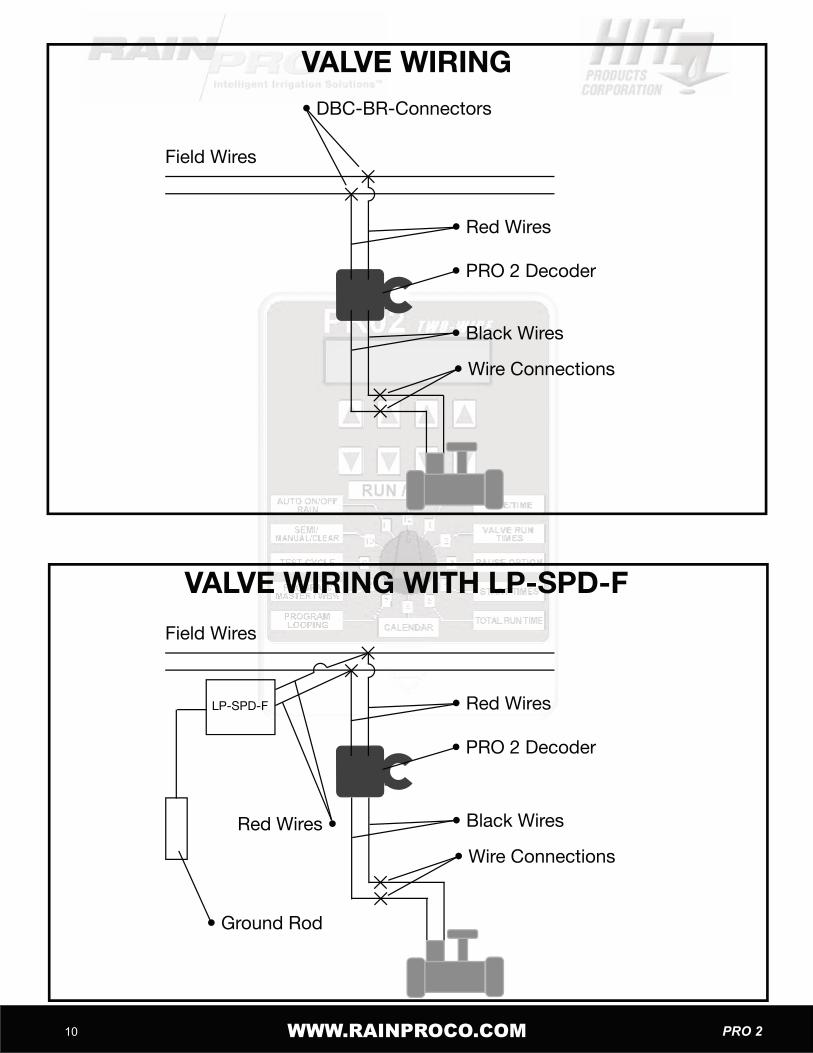
Field Wires
• PRO 2 Decoder
• Red Wires
• Black Wires
VALVE WIRING
• Wire Connections
Field Wires
• PRO 2 Decoder
• Red WiresLP-SPD-F
• Ground Rod
Red Wires •
• DBC-BR-Connectors
• Black Wires
• Wire Connections
VALVE WIRING WITH LP-SPD-F

WWW.RAINPROCO.COM WWW.RAINPROCO.COM PRO 2 ��
RAIN SENSOR
NOTE: See Rain Sensor in Programming � � Section to Activate Rain Sensor Capability.
• Rain Sensor
Use Common (C) and Normally Closed (NC) Contacts.
Field Wires
• PRO 2 Decoder
• Red Wires
• Black Wires
VALVE WIRING
• Wire Connections
Field Wires
• PRO 2 Decoder
• Red WiresLP-SPD-F
• Ground Rod
Red Wires •
• DBC-BR-Connectors
• Black Wires
• Wire Connections
VALVE WIRING WITH LP-SPD-F

WWW.RAINPROCO.COM�2 PRO 2 WWW.RAINPROCO.COM
Position 1
Current Time: Use set 2 to set hour (this will set A.M. or P.M.), use set 3 to set minutes, use set 4 to “zero out seconds.Current Date: Use set 1 to change display from date to time, use set 2 to set hour (this will set A.M. or P.M.), use set 3 to set minutes, use set 4 to “Zero out” seconds.
Position 2Valve Run Times
Use set 1 to choose the program, use set 2 to choose the valve number, use set 3 to set Use set 1 to choose the program, use set 2 to choose the valve number, use set 3 to set hours, use set 4 to set minutes. Input the total irrigation run time desired for each valve.hours, use set 4 to set minutes. Input the total irrigation run time desired for each valve.
NOTE:Program 6 valve run times can only be set in minutes and seconds. All other programs Program 6 valve run times can only be set in minutes and seconds. All other programs valve run times can be set in hours and minutes. The maximum run times can be set valve run times can be set in hours and minutes. The maximum run times can be set from 1 minute to 10 hours and 59 minutes on all programs except 6, which can be set for from 1 minute to 10 hours and 59 minutes on all programs except 6, which can be set for a minimum of 3 seconds to a maximum of 59 minutes and 59 seconds. With the water a minimum of 3 seconds to a maximum of 59 minutes and 59 seconds. With the water budget feature (position 8) these run times can be increased or decreased from 0% to budget feature (position 8) these run times can be increased or decreased from 0% to 250% in 5% increments.250% in 5% increments.
NOTE:A maximum of any 2 decoders/valves (any combination) may be operated simultaneA maximum of any 2 decoders/valves (any combination) may be operated simultane-ously.
Position 3
Pause: Use set 1 to choose the program, use set 2 or 3 to set desired time, use set 4 to Pause: Use set 1 to choose the program, use set 2 or 3 to set desired time, use set 4 to turn master valve or pump start function ON or OFF during pause function.Definitions:Pause: Amount of time delay between sequential valve openings in a programPause: Amount of time delay between sequential valve openings in a programMaster: MSTR ON will keep the master valve or pump relay ON during pause. MSTR Master: MSTR ON will keep the master valve or pump relay ON during pause. MSTR OFF will turn master valve or pump relay OFF during pause.Note: In order for the master valve to function, and the “MSTR ON” Feature to be activat-ed the master valve must be activated (see Position 8 below) for that specific program.
Input Valve Run Times:
Current Date/Current Time
Pause

WWW.RAINPROCO.COM WWW.RAINPROCO.COM PRO 2 �3
Position 4Position 4
To establish program start times, use set 1 to choose the desired program, use set 2 to choose the start number, (always use start #1 for the first start time after midnight and so on through start #6 as desired use set 3 to set the hour (A.M. and P.M.) of the start time, use set 4 to set the minutes.
NOTE:The Start Time is part of the first leg of a pre-programmed function called “Diamond Setis part of the first leg of a pre-programmed function called “Diamond Set-tings”tings” Refer to Diamond settings at the end of this programming guide for full details. Refer to Diamond settings at the end of this programming guide for full details. Refer to Diamond settings at the end of this programming guide for full details.
Position 5
To review the total run time in a specific program, use set 1 to choose the program numTo review the total run time in a specific program, use set 1 to choose the program num-ber. The total run time of that specific program is shown in the lower right hand position ber. The total run time of that specific program is shown in the lower right hand position of the display. You can review the water budget setting along with the total run time in of the display. You can review the water budget setting along with the total run time in this position. If the water budget is changed from the default of 100%, the total run times this position. If the water budget is changed from the default of 100%, the total run times will change in this position, but in position 2, the valve run times will stay as inputted. The will change in this position, but in position 2, the valve run times will stay as inputted. The actual running of the valve is determined by the input in position 2 multiplied by the water actual running of the valve is determined by the input in position 2 multiplied by the water budget setting in position 8. To review the numbered day of the calendar the controller budget setting in position 8. To review the numbered day of the calendar the controller is currently on, use set 1 to choose the program desired. The day of the calendar will be is currently on, use set 1 to choose the program desired. The day of the calendar will be displayed directly right of the word “DAY” in the upper display. You can change the day of displayed directly right of the word “DAY” in the upper display. You can change the day of the calendar by using set 3 buttons. This will or can bring all days of all programs to the the calendar by using set 3 buttons. This will or can bring all days of all programs to the same day for calendar purposes. When a 7 day Calendar has been selected. The day of same day for calendar purposes. When a 7 day Calendar has been selected. The day of the week will be displayed.the week will be displayed.Note: By adjusting the budget up or down (0% to 250%) it will change the total run time. By adjusting the budget up or down (0% to 250%) it will change the total run time. See position 8 for further discussion. The budget is the second leg of the Diamond SetSee position 8 for further discussion. The budget is the second leg of the Diamond Set-ting.
Total Run Time
Start TimeStart Time
WWW.RAINPROCO.COM�� PRO 2 WWW.RAINPROCO.COM
Position 6Position 6
The calendar is the third leg of the Diamond Setting. After programming the run times The calendar is the third leg of the Diamond Setting. After programming the run times The calendar is the third leg of the Diamond Setting. After programming the run times and the start times, the calendar will automatically establish the minimum calendar pe-riod. You can manually change the calendar to any desired period, longer than the mini-mum “Auto-calendar” period, but not shorter. By pressing set 1 to select the program, press set 2 to change the number of days desired in the calendar, (if the total run time exceeds one day, the calendar can not be set backwards. Press set 3 to review the days of the calendar. By pressing set 3 repetitively, the display above set 4 will show one of the following events: STRT (start), RUN or OFF for each day of the calendar. Note: The calendar automatically resets all programs to Day 1, today, for all programs when “Mascalendar automatically resets all programs to Day 1, today, for all programs when “Mas-ter Clear” is activated. The calendar automatically resets to Day 1, today, whenever a ter Clear” is activated. The calendar automatically resets to Day 1, today, whenever a “Program Clear” function is activated for that specific program. The calendar automati“Program Clear” function is activated for that specific program. The calendar automati-cally resets to today, Day 1, when any value in “Calendar” (Position 6) is changed. The cally resets to today, Day 1, when any value in “Calendar” (Position 6) is changed. The calendar can be manually changed to any day including today in Position 5, “Total Run calendar can be manually changed to any day including today in Position 5, “Total Run Time”. Day value has to be equal to or less than “calendar” number of days. To program Time”. Day value has to be equal to or less than “calendar” number of days. To program for ODD/EVEN use the set 2 buttons to scroll to the ODD/EVEN display use set 3 or set for ODD/EVEN use the set 2 buttons to scroll to the ODD/EVEN display use set 3 or set 4 buttons to turn ODD/EVEN ON/OFF. Rotate the dial when selection is made. 4 buttons to turn ODD/EVEN ON/OFF. Rotate the dial when selection is made.
Note: To exit “ODD/EVEN” and return to the daily calendar set both ODD and EVEN to : To exit “ODD/EVEN” and return to the daily calendar set both ODD and EVEN to off and rotate the dial out of position 6 and back. off and rotate the dial out of position 6 and back.
Note: Setting a 7 Day Calendar using the Setting a 7 Day Calendar using the set 2 arrow buttons. Select “arrow buttons. Select “Cal 7”. The actual days of the week will appear under Day in the third column. Use Set 3 to change days, days of the week will appear under Day in the third column. Use Set 3 to change days, use set 4 to select STRT or OFF use set 4 to select STRT or OFF
Definitions:Start: This is the day of the calendar that the program will start. This will be automatically : This is the day of the calendar that the program will start. This will be automatically : This is the day of the calendar that the program will start. This will be automatically set upon initial programming or set by the user. This is day 1 of the calendar, the day set upon initial programming or set by the user. This is day 1 of the calendar, the day you set up the calendar or programmed the program or let the auto-calendar set up the you set up the calendar or programmed the program or let the auto-calendar set up the calendar.Run: The total run time of the program has carried over into the second or more days : The total run time of the program has carried over into the second or more days and the program will be running these days to complete.Off: The user has programmed in additional days that the program will not be active.: The user has programmed in additional days that the program will not be active.
Note: The number of days that the calendar automatically sets up is determined as fol-lows: The number of hours from 12:00 midnight to the first start time plus the total run time, divided by 24 hours will equal the number of calendar days.
CalendarCalendar
WWW.RAINPROCO.COM WWW.RAINPROCO.COM PRO 2 �5
For calculating the calendar for “Run” Times over 24 hours. This example is for 56 hours For calculating the calendar for “Run” Times over 24 hours. This example is for 56 hours For calculating the calendar for “Run” Times over 24 hours. This example is for 56 hours Run Time per Program. Run Time per Program. Example: If a start time is 8:00 am, then the first calculation would be 8 hours plus a total run time of 56 hours for a grand total of 64 hours, divided by 24 hours would equal a 2.67 day calendar, the display would show a 3 day calendar, as follows, day 1 STRT, day 2 RUN and day 3 RUN. If you wanted to irrigate every 4th day, use set 2 to expand the calendar from 3 days to 4 days, day 4 would show OFF.
Position 7Looping Program No. 6Looping Program No. 6Any valve run times and start times set in program 6 can be looped if desired.Any valve run times and start times set in program 6 can be looped if desired.There must be individual run times for each desired valve and one start time in program There must be individual run times for each desired valve and one start time in program 6 for looping to be activated. Use set 3 and set 4 to establish the total amount of loop 6 for looping to be activated. Use set 3 and set 4 to establish the total amount of loop time desired. Use set 2 to turn looping feature ON or OFF.time desired. Use set 2 to turn looping feature ON or OFF.
Hints for using Looping:Hints for using Looping:Hints for using Looping:Hints for using Looping: Looping will run a program continuously for the amount of Looping will run a program continuously for the amount of time set in position 7 looping. For example: If looping is set for 6 hours and the start time time set in position 7 looping. For example: If looping is set for 6 hours and the start time is 8:00 am, program 6 will start at 8:00 am and run for 6 hours. A new lawn can be irriis 8:00 am, program 6 will start at 8:00 am and run for 6 hours. A new lawn can be irri-gated for 5 minutes every hour by doing the following. Valves 1, 2 and 3 operate the new gated for 5 minutes every hour by doing the following. Valves 1, 2 and 3 operate the new lawn, set run times for 5 milawn, set run times for 5 minutes each on valves 1, 2 and 3, then go to a valve that is nutes each on valves 1, 2 and 3, then go to a valve that is not being used and set run not being used and set run time for 45 minutes. You want to irrigate from 10 am until time for 45 minutes. You want to irrigate from 10 am until 5 pm. Set start time for program 6 at 10:00 am and go to position 7, set loop for 7 hours 5 pm. Set start time for program 6 at 10:00 am and go to position 7, set loop for 7 hours and turn looping ON.
The program will start at 10 am and run valve 1 for 5 minutes, then valve 2 for 5 minutes The program will start at 10 am and run valve 1 for 5 minutes, then valve 2 for 5 minutes and then valve 3 for 5 minutes and then the valve that is not being used for 45 minutes and then valve 3 for 5 minutes and then the valve that is not being used for 45 minutes and then back to valve 1 and so on until 7 hours runs out, which will be 5:00 PM.and then back to valve 1 and so on until 7 hours runs out, which will be 5:00 PM.Caution! If operating with a pump, the 45 minutes will cause “Dead Heading” on Caution! If operating with a pump, the 45 minutes will cause “Dead Heading” on Caution! If operating with a pump, the 45 minutes will cause “Dead Heading” on Caution! If operating with a pump, the 45 minutes will cause “Dead Heading” on the pump and may damage the pump or pipelinesthe pump and may damage the pump or pipelinesthe pump and may damage the pump or pipelinesthe pump and may damage the pump or pipelines
Looping Program No. 6Looping Program No. 6

WWW.RAINPROCO.COM�6 PRO 2 WWW.RAINPROCO.COM
Position 8Position 8
Use set 1 to choose the program desired, use set 2 to turn a program ON or OFF (a fully programmed program can be disabled by the this function) use set 3 to turn the master valve or pump start ON or OFF during the program running, use set 4 to increase or de-crease the budget feature of the program 0%-250%. (The amount of time in position 2 will not change in the display but the actual run time will be increased or decreased by the amount of budget %). The new “water budgeted” run times can be viewed in position the amount of budget %). The new “water budgeted” run times can be viewed in position 5.Note: The water budget is the fourth leg of the Diamond Settings (see page for more on The water budget is the fourth leg of the Diamond Settings (see page for more on the Diamond Settings).
Position 9
Use set 1 to set run time in minutes, use set 2 to set run time of seconds for test cycle, Use set 1 to set run time in minutes, use set 2 to set run time of seconds for test cycle, and use set 4 to turn ON or OFF test cycle.and use set 4 to turn ON or OFF test cycle.The controller will immediately run each valve in sequence for the predetermined run The controller will immediately run each valve in sequence for the predetermined run time for visual review of the systems operation.time for visual review of the systems operation.Note: The Master Valve setting and the pause option value for program 1 will be used : The Master Valve setting and the pause option value for program 1 will be used for the test cycle.
Position 10Semi/ Manual/ Program Clear/Master ClearSemi/ Manual/ Program Clear/Master ClearSemi- Use set 1 to choose the program you want to activate for one cycle, use set 2 to - Use set 1 to choose the program you want to activate for one cycle, use set 2 to activate that program ON. Leave the dial in number 10 position. activate that program ON. Leave the dial in number 10 position. [Rotating the dial will cancel the program.] At the conclusion, the controller will revert to automatic after 30 At the conclusion, the controller will revert to automatic after 30 minutes, without putting the rotary switch back to “Run”.minutes, without putting the rotary switch back to “Run”.Note: Within 30 minutes after the conclusion of the selected program the controller will Within 30 minutes after the conclusion of the selected program the controller will automatically revert to the “RUN” condition.
Program/Master Valves ON/OFFProgram/Master Valves ON/OFFPump StartWater Budget 0% - 250%
Test Cycle
Semi/ Manual/ Program Clear/Master ClearSemi/ Manual/ Program Clear/Master Clear

WWW.RAINPROCO.COM WWW.RAINPROCO.COM PRO 2 �7
ManualManual — Press set 3 to activate manual mode, use set 1 to choose the specific valve — Press set 3 to activate manual mode, use set 1 to choose the specific valve — Press set 3 to activate manual mode, use set 1 to choose the specific valve number to be operated manually for a predetermined time, use set 2 to set amount of number to be operated manually for a predetermined time, use set 2 to set amount of number to be operated manually for a predetermined time, use set 2 to set amount of hours to run, use set 3 to set amount of minutes, use set 4 to tell the controller whether or hours to run, use set 3 to set amount of minutes, use set 4 to tell the controller whether or hours to run, use set 3 to set amount of minutes, use set 4 to tell the controller whether or not you want the master valve or the pump start on during this manual operation. Valve not you want the master valve or the pump start on during this manual operation. Valve not you want the master valve or the pump start on during this manual operation. Valve will immediately be activated for that period of time. Leave the dial in number 10 posi-tion. [Rotating the dial will cancel the program.] At the conclusion, the controller will resume the Auto Function without turning the rotary switch back to the “RUN” position. You can activate up to 4 valves at the same time in manual mode.Note: 30 minutes after the conclusion of the selected valves the controller will automati-cally revert to the “RUN” condition.Program ClearProgram Clear: Use set 4 to choose program clear, use set 1 to choose the program that you desire to clear all the information from, use set 4 to answer yes.that you desire to clear all the information from, use set 4 to answer yes.Note: By clearing the program all information for that program is deleted.: By clearing the program all information for that program is deleted.Master Clear will clear all the information in the controller by way of the following: Turn will clear all the information in the controller by way of the following: Turn Master Clear will clear all the information in the controller by way of the following: Turn Master Clearrotary switch to position 10, press set 4, two times.rotary switch to position 10, press set 4, two times.Note: All programming data in all programs will be deleted. Only the current time and : All programming data in all programs will be deleted. Only the current time and date will remain.Note: Semi/Manual mode can be operated when controller is in “OFF” mode.: Semi/Manual mode can be operated when controller is in “OFF” mode.
Position 11
Days of delayDays of delay (controller will not run for the number of days set) press set 1 for the num (controller will not run for the number of days set) press set 1 for the num-ber of days of delay, remember the new day starts at midnight. ber of days of delay, remember the new day starts at midnight. Rain Sensor To set the Controller to recognize a Rain Sensor use set 3 button to set to To set the Controller to recognize a Rain Sensor use set 3 button to set to To set the Controller to recognize a Rain Sensor use set 3 button to set to Rain Sensor To set the Controller to recognize a Rain Sensor use set 3 button to set to Rain SensorON. When a Rain Sensor is not used leave setting OFF See Diagram.ON. When a Rain Sensor is not used leave setting OFF See Diagram.Auto Functions Use Set 4 buttons. When OFF No Auto Functions will occur. The Man Use Set 4 buttons. When OFF No Auto Functions will occur. The Man-ual and Semi Auto Functions can be used and the controller will keep day and time. ual and Semi Auto Functions can be used and the controller will keep day and time.
Position 12
In the “Run” position the controller will execute all that it has been instructed to do. AddIn the “Run” position the controller will execute all that it has been instructed to do. Add-ing new or changing existing information can be done at anytime, even with a program ing new or changing existing information can be done at anytime, even with a program running. As soon as dial is rotated and new instructions are input, the controller will interrunning. As soon as dial is rotated and new instructions are input, the controller will inter-rupt any on going activity and accept the new instructions. When the dial is returned to the “Run” position scheduled activity will resume.
To Program Decoders see PRO 2 Decoder Programming Instruction pg13.
Delay Rain ON/OFF Auto ON/OFFDelay Rain ON/OFF Auto ON/OFF
Run Program DecodersRun Program Decoders

WWW.RAINPROCO.COM�8 PRO 2 WWW.RAINPROCO.COM
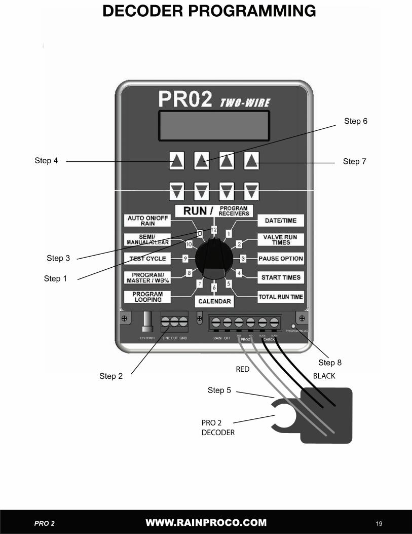
PRO 2 Decoder Programming InstructionsPRO 2 Decoder Programming Instructions
1. Set the controller in the Off position, Turn the rotary switch to position #111. Set the controller in the Off position, Turn the rotary switch to position #111. Set the controller in the Off position, Turn the rotary switch to position #11(Rain Off Auto On/Off) use the (SET 4) arrow key to turn the setting fromON to OFF.This will stop any program that is running and prevent any from starting whileprogramming decoders.2. Disconnect the 2 field wires if connected at the Terminal marked Line Out.3. Set the Rotary switch to the “Run” position. Position 12.4. Press (SET 1) arrow key up to access the Set Decoder ID screen.5. Connect the two red wires of the decoder to the programming port at the bottom of5. Connect the two red wires of the decoder to the programming port at the bottom ofthe controller board marked the controller board marked “PROG”. One Red wire in each of the Terminals One Red wire in each of the Terminalsmarked Red.Connect the decoders’ 2 black wires to the position marked “check”. One black wireConnect the decoders’ 2 black wires to the position marked “check”. One black wireeach in the Terminals marked Black. See below.each in the Terminals marked Black. See below.6. Using the arrow key corresponding directly underneath the ID number in the6. Using the arrow key corresponding directly underneath the ID number in theDisplay (Set 2) arrow key select the desired number for that decoderDisplay (Set 2) arrow key select the desired number for that decoder.7. Press the arrow key corresponding to “ENTER” on the display (right up SET7. Press the arrow key corresponding to “ENTER” on the display (right up SET 4).8. The LED on the controller marked “PROGRAMMING LED” will flash 3 times.8. The LED on the controller marked “PROGRAMMING LED” will flash 3 times.9. Remove the red and black leads.9. Remove the red and black leads.10. Install “decoder number identification tag”10. Install “decoder number identification tag”11. If programming more than one decoder repeat from step 5.11. If programming more than one decoder repeat from step 5.12. To end programming press (SET 1) down arrow key.To end programming press (SET 1) down arrow key. Controller will Controller willnot resume “RUN” automatically.not resume “RUN” automatically.13. Re-connect the field wires.13. Re-connect the field wires.14. Set the controller back to ON to resume Auto programming.Set the controller back to ON to resume Auto programming.Set the controller back to ON to resume Auto programming.Set the controller back to ON to resume Auto programming. Rotate the dial toposition #11. Press (SET 4) arrow key to turn the setting from OFF to ON.position #11. Press (SET 4) arrow key to turn the setting from OFF to ON.15. Rotate Dial to Run position #12.15. Rotate Dial to Run position #12.
Note:DO NOT PROGRAM DECODERS WITH SOLENOIDS CONNECTED.SEE FOLLOWING PAGE
WWW.RAINPROCO.COM WWW.RAINPROCO.COM PRO 2 �9
Step 4
Step 1
Step 3
Step 2
Step 5
Step 8
Step 7
Step 6
REDBLACK
PRO 2 DECODER
DECODER PROGRAMMING

WWW.RAINPROCO.COM20 PRO 2 WWW.RAINPROCO.COM
Programmable Decoder Number Identification TagsProgrammable Decoder Number Identification TagsHit Products has developed a user friendly, flexible means to identify the number of the Hit Products has developed a user friendly, flexible means to identify the number of the Hit Products has developed a user friendly, flexible means to identify the number of the field-programmed decoders during the decoder programming process. Inside every box field-programmed decoders during the decoder programming process. Inside every box field-programmed decoders during the decoder programming process. Inside every box of programmable decoders, you will find one set of identification tags numbered 1-16. You will use these decoder identification tags as follows:
1. Every time a decoder is programmed, find the corresponding numbered identification tag and immediately attach to decoder.2. To attach identification tag to decoder, insert one red decoder wire into the hole (from front to back) to the left of the appropriate numbered tag as you are looking at the num-ber. Pull red wire all the way through the hole until identification tag is approximately one ber. Pull red wire all the way through the hole until identification tag is approximately one inch from body of decoder.inch from body of decoder.Note: This will leave the engraved number unobstructed by the wire.This will leave the engraved number unobstructed by the wire.3. Insert same end of same red wire back through hole (from back of tag towards front) 3. Insert same end of same red wire back through hole (from back of tag towards front) and continue to pull wire through until tight. The number on the tag should now be readand continue to pull wire through until tight. The number on the tag should now be read-ily visible4. Should decoder ever be reprogrammed to a different number, make sure to replace 4. Should decoder ever be reprogrammed to a different number, make sure to replace the identification tag with the appropriately numbered identification tag. Failure to do so the identification tag with the appropriately numbered identification tag. Failure to do so can create extreme confusion!can create extreme confusion!

WWW.RAINPROCO.COM WWW.RAINPROCO.COM PRO 2 2�
DIAMOND SETTINGSDIAMOND SETTINGSThe DS, as we call it, is an automatic calendar setting after run times and start times are The DS, as we call it, is an automatic calendar setting after run times and start times are The DS, as we call it, is an automatic calendar setting after run times and start times are entered. The DS will set the minimum days of the irrigation calendar. This is to protect entered. The DS will set the minimum days of the irrigation calendar. This is to protect entered. The DS will set the minimum days of the irrigation calendar. This is to protect against overlapping within a program. After initial programming of the PRO 2, run times and start times, the DS will not allow you to enter additional run times or increase the budget so that it will exceed the current calendar days set.If you are unable to increase run times, check your “total run time” in position 5. If the “total run time” for that program is close to the number of current calendar days for that program you may have to increase the number of calendar days to get the controller to accept increased run times, increased water budget or adding more valves with run times to that program. The same is true of increasing the water budget; the calendar times to that program. The same is true of increasing the water budget; the calendar may have to be extended to accommodate the extended run times to allow the program may have to be extended to accommodate the extended run times to allow the program to complete its cycle.The DS sets the calendar automatically as follows. The start time entered is calculated The DS sets the calendar automatically as follows. The start time entered is calculated as to how many hours past 12 midnight it is, for example an 8AM start time would be 8 as to how many hours past 12 midnight it is, for example an 8AM start time would be 8 hours from midnight or the start of that day, then the DS looks at total run times including hours from midnight or the start of that day, then the DS looks at total run times including pause time and adds the time from midnight to the startpause time and adds the time from midnight to the starttime together. If the total time exceeds 24 hours the calendar is set for two days,If the total time exceeds 24 hours the calendar is set for two days,If the total time exceeds 24 hours the calendar is set for two days,If the total time exceeds 24 hours the calendar is set for two days, if the total time exceeds 48 hours the calendar is set to a three-day calendar and so on. the total time exceeds 48 hours the calendar is set to a three-day calendar and so on. The first day will be set as a STRT day (Start) the following day will be “run” days. The The first day will be set as a STRT day (Start) the following day will be “run” days. The day you programmed this program, automatically becomes day 1 of the calendar, for day you programmed this program, automatically becomes day 1 of the calendar, for example a three-day calendar programmed on Monday would look like the following:example a three-day calendar programmed on Monday would look like the following:
Day 1 STRT would be MondayDay 1 STRT would be MondayDay 2 RUN would be TuesdayDay 2 RUN would be TuesdayDay 3 RUN would be WednesdayDay 3 RUN would be WednesdayDay 1 STRT would be ThursdayDay 1 STRT would be ThursdayDay 2 RUN would be FridayDay 2 RUN would be Friday
And so on; please note that any calendar not divisible by 7 will run on different days of And so on; please note that any calendar not divisible by 7 will run on different days of the week as the year progresses. If the above example were changed to a five-day calthe week as the year progresses. If the above example were changed to a five-day cal-endar the days 4 and 5 would show OFF.
Note: It is important to remember if the total run time of a program is under 23 hours and 59 minutes; the DS automatically sets the calendar to one day. Even if the start time is set to allow the program to run past midnight into the next day. The same is true if multiple start times are used in the same program and the total runtime of the program multiplied by the number of start times is under 23 hours and 59 minutes. The DS will not allow multiple start times that total more than 23 hours and 59 minutes.

WWW.RAINPROCO.COM22 PRO 2 WWW.RAINPROCO.COM
Two Wire OperationTwo Wire Operation
Controller OperationController OperationController OperationWhen the controller is activated by either “Auto” programming or a “Manual” Input, the power and an encoded signal is supplied to the Line Out Terminals.
Decoder OperationsDecoder OperationsThe Decoder operates as an electronically controlled switch. When the decoder recog-nizes the encoded signal that matches its programmed data, it then allows or “switches” power to the solenoid on the valve.
Line Short/Valve Short CodesLine Short/Valve Short CodesThe controller, through its current monitoring ability, can display two fault conditions: One The controller, through its current monitoring ability, can display two fault conditions: One being “Short Line” the second being “Valve Short.” These faults are triggered when curbeing “Short Line” the second being “Valve Short.” These faults are triggered when cur-rent draw has exceeded a pre-set level.rent draw has exceeded a pre-set level.
Note: No Output is sent to the field during the following conditions:Note: No Output is sent to the field during the following conditions:
• If excessive current draw is sensed at a programs initial start a “ • If excessive current draw is sensed at a programs initial start a “Line Short” will be displayed. will be displayed. • If excessive current draw is sensed during a specific valve run time • If excessive current draw is sensed during a specific valve run time
then “Short Valve” with a valve number will be displayed. then “Short Valve” with a valve number will be displayed. then “Short Valve” with a valve number will be displayed. then “Short Valve” with a valve number will be displayed.
“Short line” will retry after 20 minutes. Turning the dial out of “Run” and back will clear will retry after 20 minutes. Turning the dial out of “Run” and back will clear the display. The controller will then try to continue any scheduled program. If the short the display. The controller will then try to continue any scheduled program. If the short has not been corrected the controller will go back into “Line Short.”has not been corrected the controller will go back into “Line Short.”
“Short Valve” will stay displayed during that specific valve’s run time. The controller will will stay displayed during that specific valve’s run time. The controller will monitor the program status and standard operation will resume when the next valve is monitor the program status and standard operation will resume when the next valve is activated. If the problem has not been corrected by the time the controller is scheduled to activated. If the problem has not been corrected by the time the controller is scheduled to Run again the “Short Valve” will repeat for that specific valve until the short is repaired.Run again the “Short Valve” will repeat for that specific valve until the short is repaired.No irrigation will occur for that specific valve’s run time but all valves that do not have a No irrigation will occur for that specific valve’s run time but all valves that do not have a “short” condition will continue to irrigate as programmed.
Note: These high current draw codes are designed to protect the controller and transformer. In extremely long wire runs the current level may not be reached to activate “Line Short” or “Short Valve ” due to line loss.or “Short Valve ” due to line loss.or

WWW.RAINPROCO.COM WWW.RAINPROCO.COM PRO 2 23
TROUBLESHOOTING HINTS FOR PRO 2 TWO WIRE SYSTEMSTROUBLESHOOTING HINTS FOR PRO 2 TWO WIRE SYSTEMSTROUBLESHOOTING HINTS FOR PRO 2 TWO WIRE SYSTEMS
PROBLEM SOLUTION
Display Blank No Power 1) Check: 110v or 220v supply and connec-tions. Correct as needed2) Check: 12 V Power at the controller board terminals.
Controller Operates in “Manual” or “Test” but not in “Auto”
Incorrect ProgrammingController is OFFProgram is OFFNo start timesCalendar not set correctlyWater budget set at zero
Correct ProgrammingSee the Programming section of this See the Programming section of this ManualManual
Controller Displaying “Short Line” or Turn-Controller Displaying “Short Line” or Turn-ing ON/OFF and “Clicking”
High Current Draw1) More than 4 valves activating2) Short field wires3) Field wires of one controller connected to field wires of a second controller
1) Possible failed Decoder1) Possible failed Decoder2) Field wires shorted2) Field wires shorted
No Valves Activating 1) Controller not activating2) Field Wire Connection
1) See “Controller Operates in Manual and 1) See “Controller Operates in Manual and Test but not Auto” LineTest but not Auto” Line2) Check the “Out” wire connections at the 2) Check the “Out” wire connections at the Controller.Controller.3) Failed Controller Replace Panel3) Failed Controller Replace Panel
Single Valve not Activating 1) Bad wire connection2) Failed Decoder
1) Check Decoder Wire Connection1) Check Decoder Wire Connection2) See Decoder Operation2) See Decoder Operation
Multiple Valves not Activating 1) Field wiring or connections 1) Check wiring and connections between 1) Check wiring and connections between the last valve working and the first valve the last valve working and the first valve not working.not working.
Display reads “Rain Off” Controller is in Rain Off condition 1) Rain Switch has activated a bad connec-Controller is in Rain Off condition 1) Rain Switch has activated a bad connec-Controller is in Rain Off condition 1) Rain Switch has activated a bad connec-tion from Controller to Rain Switchtion from Controller to Rain Switch
PROBLEMS SOLUTIONSSOLUTIONS
Display is flashing “Rain Off” Power is being supplied to Rain Off con-nector
Incorrect Rain SwitchIncorrect Rain Switch
Controller displaying reads “Valve Short” Controller displaying reads “Valve Short” with a valve number
High current draw during valve run time 1) Possible bad solenoidHigh current draw during valve run time 1) Possible bad solenoidHigh current draw during valve run time 1) Possible bad solenoidHigh current draw during valve run time 1) Possible bad solenoid2) Shorted wires between decoder and solenoid
Display frozen, does not respond to rotat-ing valve
Micro is locked 1) Turn power off for a minute, then back on
Valves Turning ON/OFF during run time Possible EMF interferenceValves Turning ON/OFF during run time Possible EMF interference Check: Controller, Decoder and Field Wir-ing location in respect to any high voltage.

WWW.RAINPROCO.COM 24 PRO 2
Statement regarding Wire Sizing for the PRO2 –CStatement regarding Wire Sizing for the PRO2 –C
FAQ’s
The Pro2 Controller and two wire output is designed for use with standard single strand solid core copper wire to accommodate a two wire path run not to exceed a 2,000’direct wire path from the Controller to the valve. Total wire in system may exceed the single station maximum distance of 2,000’.single station maximum distance of 2,000’.
Q:It has been asked what about increasing wire size to get longer wire runs.:It has been asked what about increasing wire size to get longer wire runs.A: The answer to the question is that the Controller’s two wire communication transmit: The answer to the question is that the Controller’s two wire communication transmit-ting capability will not reliably operate beyond a distance of 2,000’ting capability will not reliably operate beyond a distance of 2,000’ regardless of wire size.
NOTE:Controller specifications are based on a Standard 24VAC irrigation valve solenoid rated Controller specifications are based on a Standard 24VAC irrigation valve solenoid rated with a maximum 350 mA inrush and a maximum 250 mA holding current at 24VAC. with a maximum 350 mA inrush and a maximum 250 mA holding current at 24VAC. Controller is not compatible with Low Power / Diode Bridge solenoidController is not compatible with Low Power / Diode Bridge solenoid


P.O. BOX 929, 556 S. Mirage AvenueLindsay, CA 93247
For Technical Support: 800-400-0071 ext. 115
© 2008 HIT PRODUCTS CORPORATION
MADE IN THE USA
9/08 REV
™