combination ph/orp two-wire transmitters - … ph/orp two-wire transmitters ... x 100 = 49.0 % 4....
TRANSCRIPT
������������� �
Combination pH/ORP Two-Wire Transmitters
Instruction ManualPN 51-1181pH/rev.BMarch 2003
DANGERHAZARDOUS AREA INSTALLATION
INTRINSICALLY SAFE INSTALLATIONTransmitter/Sensor is not Intrinsically safe.Installations in hazardous area locations must becarefully evaluated by qualified on site safety per-sonnel. To secure and maintain an intrinsically safeinstallation, an appropriate safety barrier must beused and the installation must be performed inaccordance with the governing approval agency(FM, CSA or BASEEFA/ CENELEC) installationdrawing requirements (see Section 2.0-Installation).
EXPLOSION-PROOF INSTALLATIONSensors are not explosion-proof and must beinstalled in a non-hazardous location. If the sensormust be installed in a hazardous location an intrin-sically safe system must be implemented. To main-tain the explosion-proof rating of the transmitter,the following conditions must be met:• Discontinue power supply before removing
enclosure covers.• Transmitter covers must be properly installed
during power on operation.• Explosion proof "Y" fittings must be properly
installed with sealing compound prior to applyingpower to the transmitter.
• Serial tag cover over the external Zero and Spanadjustments must be in place.
• See Installation Section for details.Proper installation, operation and servicing of thisinstrument in a Hazardous Area Installation isentirely the responsibility of the user.
ESSENTIAL INSTRUCTIONSREAD THIS PAGE BEFORE PROCEEDING!
Rosemount Analytical designs, manufactures, and tests its products tomeet many national and international standards. Because these instru-ments are sophisticated technical products, you must properly install,use, and maintain them to ensure they continue to operate within theirnormal specifications. The following instructions must be adhered toand integrated into your safety program when installing, using, andmaintaining Rosemount Analytical products. Failure to follow the prop-er instructions may cause any one of the following situations to occur:Loss of life; personal injury; property damage; damage to this instru-ment; and warranty invalidation.
• Read all instructions prior to installing, operating, and servicing theproduct. If this Instruction Manual is not the correct manual, tele-phone 1-800-654-7768 and the requested manual will be provided.Save this Instruction Manual for future reference.
• If you do not understand any of the instructions, contact yourRosemount representative for clarification.
• Follow all warnings, cautions, and instructions marked on and sup-plied with the product.
• Inform and educate your personnel in the proper installation, opera-tion, and maintenance of the product.
• Install your equipment as specified in the Installation Instructions ofthe appropriate Instruction Manual and per applicable local andnational codes. Connect all products to the proper electrical andpressure sources.
• To ensure proper performance, use qualified personnel to install,operate, update, program, and maintain the product.
• When replacement parts are required, ensure that qualified peopleuse replacement parts specified by Rosemount. Unauthorized partsand procedures can affect the product’s performance and place thesafe operation of your process at risk. Look alike substitutions mayresult in fire, electrical hazards, or improper operation.
• Ensure that all equipment doors are closed and protective coversare in place, except when maintenance is being performed by qual-ified persons, to prevent electrical shock and personal injury.
Emerson Process Management
Rosemount Analytical Inc.2400 Barranca ParkwayIrvine, CA 92606 USATel: (949) 757-8500Fax: (949) 474-7250
http://www.raihome.com
© Rosemount Analytical Inc. 2003
About This DocumentThis manual contains instructions for installation and operation of the Model 1181 pH/ORP Two-wiretransmitter. The following list provides notes concerning all revisions of this document.
Rev. Level Date Notes
A 7/01 This is the initial release of the product manual. The manual has been reformatted to reflect the Emerson documentation style and updated to reflect any changes in the product offering and agency certification.
B 3/03 Updated CE information.
i
MODEL 1181 pH/ORP QUICK START-UP
QUICK START-UP
I. Set up
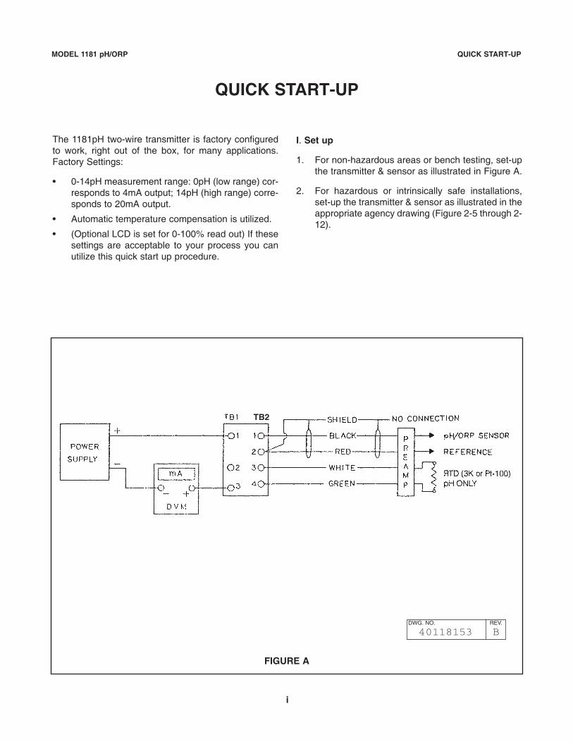
1. For non-hazardous areas or bench testing, set-upthe transmitter & sensor as illustrated in Figure A.
2. For hazardous or intrinsically safe installations,set-up the transmitter & sensor as illustrated in theappropriate agency drawing (Figure 2-5 through 2-12).
The 1181pH two-wire transmitter is factory configuredto work, right out of the box, for many applications.Factory Settings:
• 0-14pH measurement range: 0pH (low range) cor-responds to 4mA output; 14pH (high range) corre-sponds to 20mA output.
• Automatic temperature compensation is utilized.
• (Optional LCD is set for 0-100% read out) If thesesettings are acceptable to your process you canutilize this quick start up procedure.
FIGURE A
DWG. NO. REV.
40118153 B
TB2
ii
MODEL 1181 pH/ORP QUICK START-UP
7. Repeat Step 2 through 7 until no further adjust-ments are required. Rinse the sensor in cleanwater prior to placing it in a different buffer solu-tion.
8. Remove DVM and connect power supply enddirectly to the transmitter.
III. Standardize to the Process
A slight adjustment of the 1181 ZERO pot may be nec-essary to fine tune the loop to your process.
1. Install sensor into it’s final mounting position, andallow sensor to acclimate to the process temp.(Wait for reading to stabilize).
2. Take a grab sample of the process, close to thesensor, and have it analyzed. Note the pH value.
3. Adjust the 1181 ZERO control (under serial label)until the display reads the percentages of full-scalethat corresponds to the grab sample pH value.
Grab Sample pH14 pH
X 100 = % of full scale
6.8614 pH
X 100 = 49.0 %
4. Start-up and calibration is now complete. Refer to1181pH manual for further details on 1181 fea-tures.
II. Solution Calibration
1. Obtain two buffer solutions. One should representa low range, and the other a high range value.Typical buffer solution values 4pH, 7 pH & 10 pH.
2. Place the sensor in the lower range buffer solu-tion, allow the reading to stabilize.
3. a. adjust ZERO control (under the serial label)until the DVM reads the current output valuethat corresponds to the buffer value.
Buffer value-Low pH rangemA =___________________________ x 16 mA + 4mA
High pH range-Low pH range
Example: For 4 pH buffer solution; Range of 0-14 pH
4 pH-0 pHEx.= __________ x 16 mA + 4 mA= 8.57 mA
14 pH-0 pH
b. If a liquid crystal display is installed, adjust theLCD ZERO pot (on LCD face) until the displayindicates the proper percentage of full scalevalue.
Buffer pH value% Reading =______________x 16 mA + 4 mA
High pH range
4 pHEx.=______ x 100 = 28.6%
14 pH
4. Remove the sensor from the low range buffer, andrinse it in clean water.
5. Place the sensor in high range buffer, and allowthe reading to stabilize.
6. a. adjust the SPAN control (under serial label) untilDVM reads the current output value that corre-sponds to the computed buffer value.
10 pH-0 pHEx.= __________ x 16 mA + 4 mA= 15.43 mA
14 pH-0 pH
b. If a LCD is installed, adjust the LCD SPAN pot(on LCD face), until the display indicates theproper percentage of the computed full-scalevalue.
10 pHEx.=______ x 100 = 71.4%
14 pH
MODEL 1181 pH/ORP TABLE OF CONTENTS
MODEL 1181pH/ORPTWO-WIRE TRANSMITTERS
TABLE OF CONTENTSSection Title Page
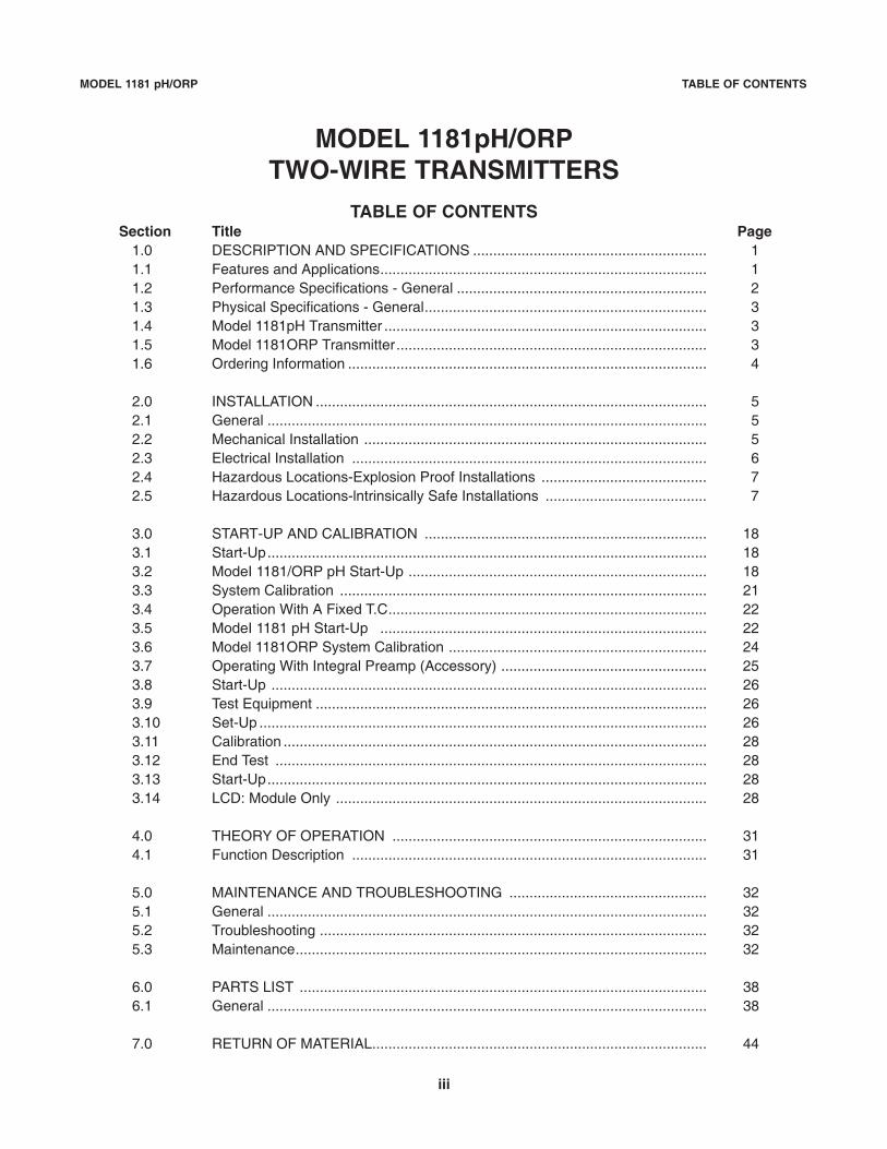
1.0 DESCRIPTION AND SPECIFICATIONS .......................................................... 11.1 Features and Applications................................................................................. 11.2 Performance Specifications - General .............................................................. 21.3 Physical Specifications - General...................................................................... 31.4 Model 1181pH Transmitter ................................................................................ 31.5 Model 1181ORP Transmitter............................................................................. 31.6 Ordering Information ......................................................................................... 4
2.0 INSTALLATION ................................................................................................. 52.1 General ............................................................................................................. 52.2 Mechanical Installation ..................................................................................... 52.3 Electrical Installation ........................................................................................ 62.4 Hazardous Locations-Explosion Proof Installations ......................................... 72.5 Hazardous Locations-lntrinsically Safe Installations ........................................ 7
3.0 START-UP AND CALIBRATION ...................................................................... 183.1 Start-Up............................................................................................................. 183.2 ModeI 1181/ORP pH Start-Up .......................................................................... 183.3 System Calibration ........................................................................................... 213.4 Operation With A Fixed T.C............................................................................... 223.5 ModeI 1181 pH Start-Up ................................................................................. 223.6 Model 1181ORP System Calibration ................................................................ 243.7 Operating With Integral Preamp (Accessory) ................................................... 253.8 Start-Up ............................................................................................................ 263.9 Test Equipment ................................................................................................. 263.10 Set-Up ............................................................................................................... 263.11 Calibration ......................................................................................................... 283.12 End Test ........................................................................................................... 283.13 Start-Up............................................................................................................. 283.14 LCD: Module Only ............................................................................................ 28
4.0 THEORY OF OPERATION .............................................................................. 314.1 Function Description ........................................................................................ 31
5.0 MAINTENANCE AND TROUBLESHOOTING ................................................. 325.1 General ............................................................................................................. 325.2 Troubleshooting ................................................................................................ 325.3 Maintenance...................................................................................................... 32
6.0 PARTS LIST ..................................................................................................... 386.1 General ............................................................................................................. 38
7.0 RETURN OF MATERIAL................................................................................... 44
iii
MODEL 1181 pH/ORP TABLE OF CONTENTS
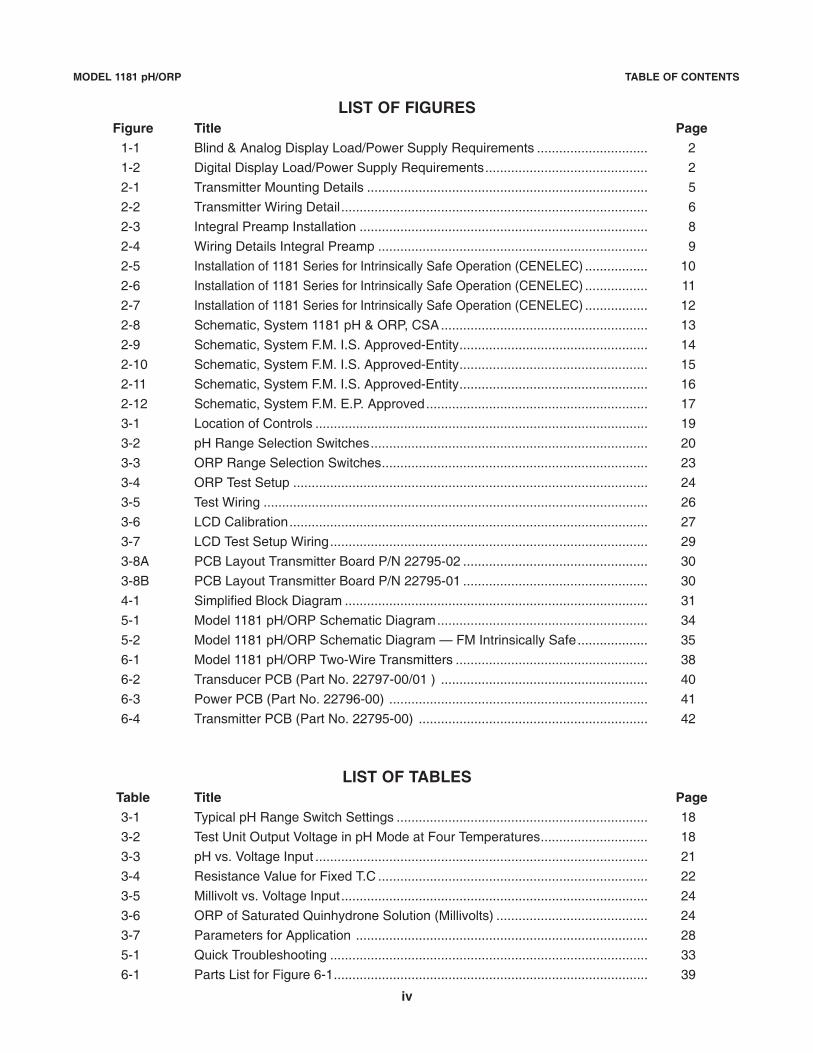
LIST OF FIGURESFigure Title Page
1-1 Blind & Analog Display Load/Power Supply Requirements .............................. 2
1-2 Digital Display Load/Power Supply Requirements............................................ 2
2-1 Transmitter Mounting Details ............................................................................ 5
2-2 Transmitter Wiring Detail................................................................................... 6
2-3 Integral Preamp Installation .............................................................................. 8
2-4 Wiring Details Integral Preamp ......................................................................... 9
2-5 Installation of 1181 Series for Intrinsically Safe Operation (CENELEC) ................. 10
2-6 Installation of 1181 Series for Intrinsically Safe Operation (CENELEC) ................. 11
2-7 Installation of 1181 Series for Intrinsically Safe Operation (CENELEC) ................. 12
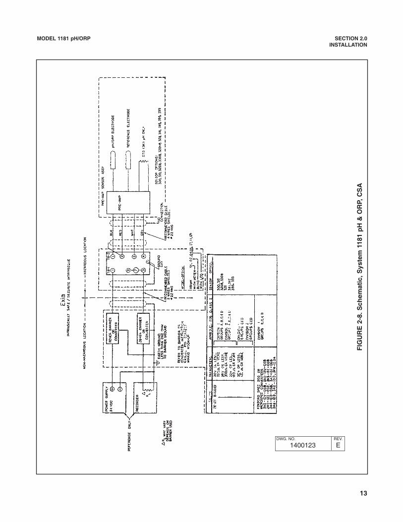
2-8 Schematic, System 1181 pH & ORP, CSA........................................................ 13
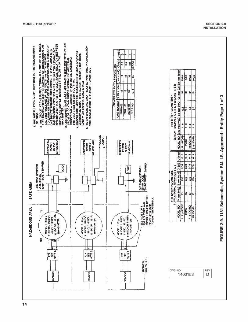
2-9 Schematic, System F.M. I.S. Approved-Entity................................................... 14
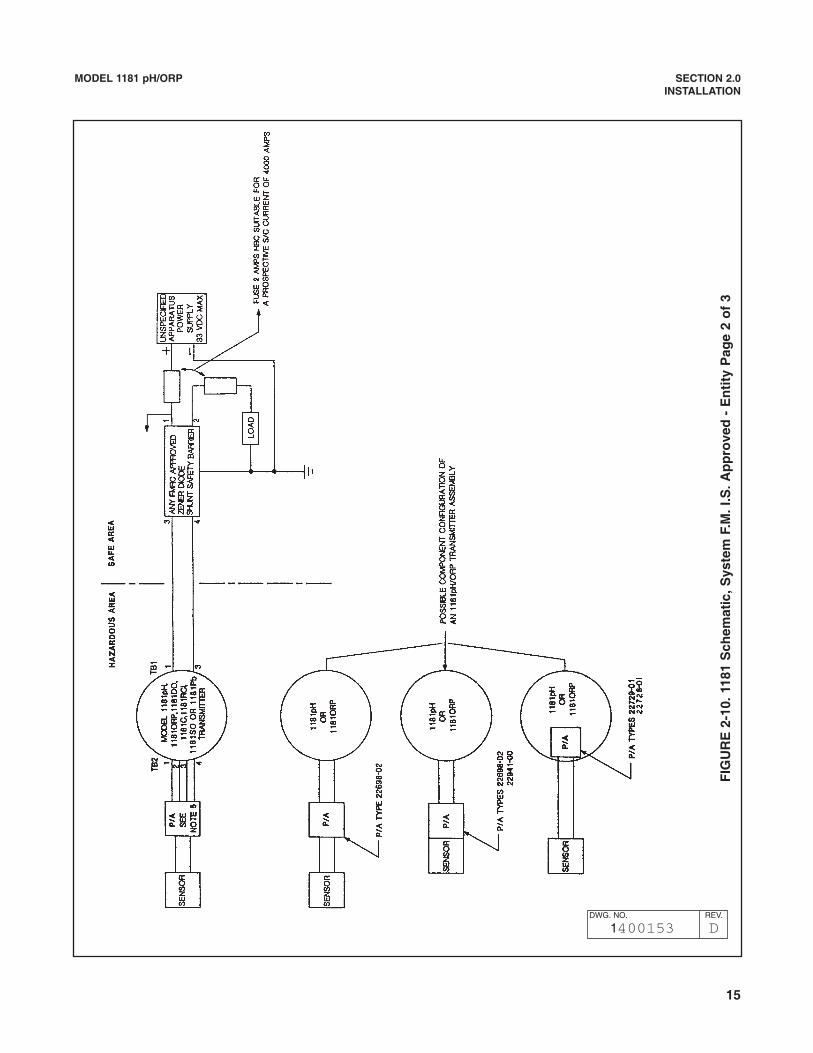
2-10 Schematic, System F.M. I.S. Approved-Entity................................................... 15
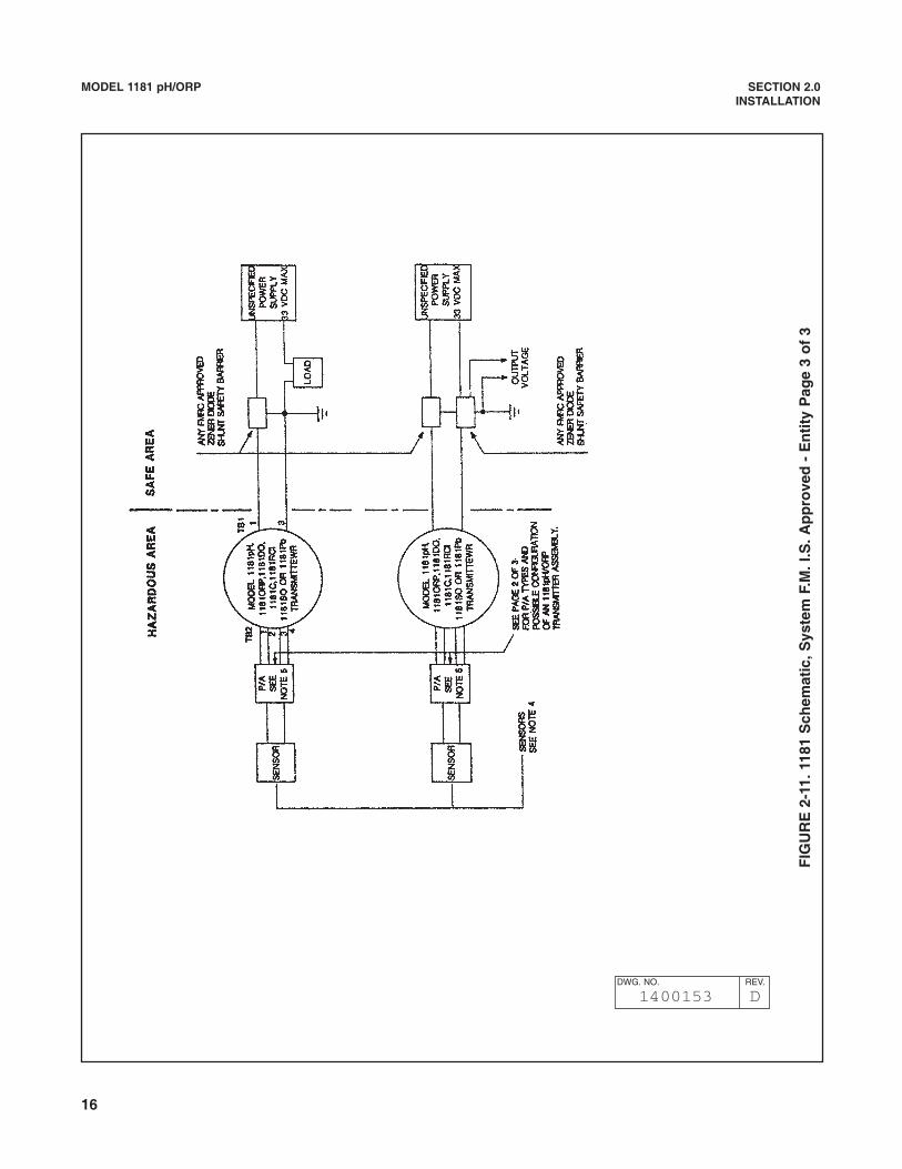
2-11 Schematic, System F.M. I.S. Approved-Entity................................................... 16
2-12 Schematic, System F.M. E.P. Approved............................................................ 17
3-1 Location of Controls .......................................................................................... 19
3-2 pH Range Selection Switches........................................................................... 20
3-3 ORP Range Selection Switches........................................................................ 23
3-4 ORP Test Setup ................................................................................................ 24
3-5 Test Wiring ........................................................................................................ 26
3-6 LCD Calibration................................................................................................. 27
3-7 LCD Test Setup Wiring...................................................................................... 29
3-8A PCB Layout Transmitter Board P/N 22795-02 .................................................. 30
3-8B PCB Layout Transmitter Board P/N 22795-01 .................................................. 30
4-1 Simplified Block Diagram .................................................................................. 31
5-1 Model 1181 pH/ORP Schematic Diagram......................................................... 34
5-2 Model 1181 pH/ORP Schematic Diagram — FM Intrinsically Safe................... 35
6-1 Model 1181 pH/ORP Two-Wire Transmitters .................................................... 38
6-2 Transducer PCB (Part No. 22797-00/01 ) ........................................................ 40
6-3 Power PCB (Part No. 22796-00) ...................................................................... 41
6-4 Transmitter PCB (Part No. 22795-00) .............................................................. 42
LIST OF TABLESTable Title Page3-1 Typical pH Range Switch Settings .................................................................... 18
3-2 Test Unit Output Voltage in pH Mode at Four Temperatures............................. 18
3-3 pH vs. Voltage Input .......................................................................................... 21
3-4 Resistance Value for Fixed T.C ......................................................................... 22
3-5 Millivolt vs. Voltage Input................................................................................... 24
3-6 ORP of Saturated Quinhydrone Solution (Millivolts) ......................................... 24
3-7 Parameters for Application ............................................................................... 28
5-1 Quick Troubleshooting ...................................................................................... 33
6-1 Parts List for Figure 6-1..................................................................................... 39
iv

1
MODEL 1181pH/ORP SECTION 1.0DESCRIPTION AND SPECIFICATIONS
SECTION 1.0DESCRIPTION AND SPECIFICATIONS
• TWO-WIRE FIELD MOUNTED TRANSMITTERS. Ideal for multiple loop installationswhere central data processing and control are required. Field mounting near the sensor forease in routine calibration.
• NEMA 4X WEATHERPROOF, CORROSION-RESISTANT, DUAL COMPARTMENT HOUS-ING provides maximum circuit protection for increased reliability in industrial environments.
• HAZARDOUS AREA INSTALLATION. Certified NEMA 7B explosion-proof and intrinsicallysafe when used with an approved sensor and safety barrier.
• COMMONALITY OF PARTS reduces inventory required to support different field measure-ments.
• SWITCH SELECTABLE RANGES further reduces inventory by permitting calibration ofone Model to virtually any Tag Number requiring the same measurement.
• EXTERNAL ZERO AND SPAN, 20-turn potentiometers provide for fine calibration of theisolated 4-20 mA output signal.
1.1 FEATURES AND APPLICATIONS
The Rosemount Analytical Two-Wire field mountedtransmitters, with the appropriate sensors, aredesigned to continuously measure the pH, ORP,Conductivity, Dissolved Oxygen, or Free ResidualChlorine in industrial processes.
The Model 1181 Transmitters include all the circuitrynecessary for the measurement and transmission ofan isolated 4-20 mA linear signal. Measurement rangeselection is made through internal range switches thatare easily accessed by removing a housing cover. Nofurther disassembly is required. A matrix is providedwhich conveniently indicates the proper switch posi-tion. Range selection can be made without the use ofthe instruction manual. Fine calibration of the 4-20 mAsignal is accomplished with the 20-turn external Zeroand Span potentiometers.
The electronic printed circuits are protected from theenvironment by the NEMA 4X weatherproof, corrosionresistant enclosure. The printed circuit cards plug into amoisture barrier which is isolated from the field wiringand calibration terminals. Routine field calibration doesnot require exposing the electronics to harsh industrialenvironments. All PCBs are conformal coated for maxi-mum protection. The PCBs are removed as a unit andmay be individually replaced. The transmitter housingcovers are sealed with large cross sectional O-rings andneed not be replaced each time the cover is removed.
The Model 1181 is available with or without an analogor digital display. The digital display may be calibrat-ed in engineering units and the analog display fea-tures multiple scales in engineering units.
The transmitters are certified explosion-proof, NEMA7B, and intrinsically safe when installed with anapproved barrier and sensor. Hazardous area certifi-cates are provided by BASEEFA to CENELEC regula-tions, FM, CSA, SAA, SEV, and TUV. CSA hasdetermined that the moisture barrier qualifies asFactory Sealed which means Explosion Proof Y fittingsand sealing compound are not required for installationwhen this approval is selected.
Accessory items are available for the two-wire transmit-ters. The Model 515 Isolated Power Supply providespower for up to 20 transmitters. Two transmitters maybe wired directly to the power supply. For more thantwo transmitters, junction boxes are available, eachaccommodating wiring for a maximum of ten transmit-ters. Remote alarms are available with independentlyadjustable set points and hysteresis. Contacts of theModel 230A may be specified for high/low, high/high, orlow/low operation. The impedance of the Model 230AAlarm Module is less than 100 ohms. For further infor-mation on the Models 515 and 230A, please refer to totheir respective product data sheet.
2
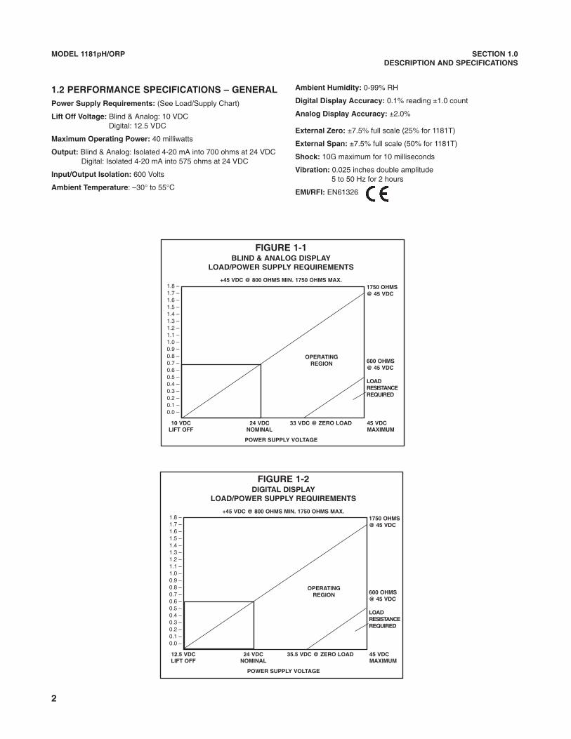
1.2 PERFORMANCE SPECIFICATIONS – GENERALPower Supply Requirements: (See Load/Supply Chart)
Lift Off Voltage: Blind & Analog: 10 VDCDigital: 12.5 VDC
Maximum Operating Power: 40 milliwatts
Output: Blind & Analog: Isolated 4-20 mA into 700 ohms at 24 VDCDigital: Isolated 4-20 mA into 575 ohms at 24 VDC
Input/Output Isolation: 600 Volts
Ambient Temperature: –30° to 55°C
Ambient Humidity: 0-99% RH
Digital Display Accuracy: 0.1% reading ±1.0 count
Analog Display Accuracy: ±2.0%
External Zero: ±7.5% full scale (25% for 1181T)
External Span: ±7.5% full scale (50% for 1181T)
Shock: 10G maximum for 10 milliseconds
Vibration: 0.025 inches double amplitude5 to 50 Hz for 2 hours
EMI/RFI: EN61326
MODEL 1181pH/ORP SECTION 1.0DESCRIPTION AND SPECIFICATIONS
FIGURE 1-1BLIND & ANALOG DISPLAY
LOAD/POWER SUPPLY REQUIREMENTS
+45 VDC @ 800 OHMS MIN. 1750 OHMS MAX.
10 VDC 24 VDC 33 VDC @ ZERO LOAD 45 VDCLIFT OFF NOMINAL MAXIMUM
POWER SUPPLY VOLTAGE
1750 OHMS@ 45 VDC
600 OHMS@ 45 VDC
LOADRESISTANCEREQUIRED
1.8 –1.7 –1.6 –1.5 –1.4 –1.3 –1.2 –1.1 –1.0 –0.9 –0.8 –0.7 –0.6 –0.5 –0.4 –0.3 –0.2 –0.1 –0.0 –
OPERATINGREGION
FIGURE 1-2DIGITAL DISPLAY
LOAD/POWER SUPPLY REQUIREMENTS
+45 VDC @ 800 OHMS MIN. 1750 OHMS MAX.
12.5 VDC 24 VDC 35.5 VDC @ ZERO LOAD 45 VDCLIFT OFF NOMINAL MAXIMUM
POWER SUPPLY VOLTAGE
1750 OHMS@ 45 VDC
600 OHMS@ 45 VDC
LOADRESISTANCEREQUIRED
1.8 –1.7 –1.6 –1.5 –1.4 –1.3 –1.2 –1.1 –1.0 –0.9 –0.8 –0.7 –0.6 –0.5 –0.4 –0.3 –0.2 –0.1 –0.0 –
OPERATINGREGION
3
MODEL 1181pH/ORP SECTION 1.0DESCRIPTION AND SPECIFICATIONS
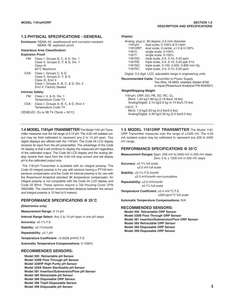
1.3 PHYSICAL SPECIFICATIONS - GENERALEnclosure: NEMA 4X, weatherproof and corrosion-resistant
NEMA 7B, explosion proof
Hazardous Area Classification:Explosion Proof:
FM: Class I, Groups B, C, & D, Div. 1Class II, Groups E, F, & G, Div. 1Class III60°C Maximum
CSA: Class I, Groups C, & D, Class II, Groups E, F, & GClass III, Encl 4Class I, Groups A, B, C, & D, Div. 2Encl 4, Factory Sealed
Intrinsic Safety:FM: Class I, II, & III, Div. 1
Temperature Code T4CSA: Class I, Groups A, B, C, & D, Encl 4
Temperature Code T4
CENELEC: Ex ia IIB T4 (Tamb = 55°C)
Display:
Analog: plug in, 90 degree, 2.5 inch diameter1181pH: dual scale, 0-100% & 0-14pH1181ORP: dual scale, 0 center, ±1.0 & 0-100%1181C: single scale, 0-100%1181T: single scale, 0-100%1181DO: triple scale, 0-5, 0-10, 0-20 ppm1181PB: triple scale, 0-5, 0-10, 0-20 ppb X101181SO: triple scale, 0-100, 0-200, 0-800 mm Hg1181RC: triple scale, 0-5, 0-10, 0-20 ppm
Digital: 3.5 digit, LCD, adjustable range in engineering units
Recommended Cable: Transmitter to Power SupplyTwo Wire, 18 AWG, shielded, Belden 8760 or equal (Rosemount Analytical P/N 9200001)
Weight/Shipping Weight:
1181pH, ORP, DO, PB, SO, RC, CL:Blind: 1.44 kg/1.89 kg (3.18 lbs/4.18 lbs)Analog/Digital: 2.15 kg/2.6 kg (4.74 lbs/5.75 lbs)
1181C, T:Blind: 1.8 kg/2.25 kg (4.0 lbs/5.0 lbs)Analog/Digital: 2.48 kg/2.93 kg (5.5 lbs/6.5 lbs)
1.4 MODEL 1181pH TRANSMITTER The Model 1181 pH Trans-mitter measures over the full range of 0-14 pH. The 4-20 mA isolated out-put may be field calibrated to represent any 2 to 14 pH span. Twodigital displays are offered with the 1181pH. The Code 04 LCD displayreceives its input from the pH preamplifier. The advantage of the Code04 display is that it will continue to display the measured pH regardlessof the calibrated output. The Code 06 LCD display and the analog dis-play receive their input from the 4-20 mA loop current and will displaypH to the calibrated output only.
The 1181pH Transmitter is available with an integral preamp. TheCode 43 integral preamp is for use with sensors having a PT100 tem-perature compensator and the Code 44 internal preamp is for use withthe Rosemount Analytical standard 3K temperature compensator. Anintegral preamp is not compatible with the Code 04 LCD display andCode 02 Blind. These options require a Tall Housing Cover (P/N3002468). The maximum recommended distance between the sensorand integral preamp is 15 feet (4.5 meters).
PERFORMANCE SPECIFICATIONS @ 25°C(Electronics only)
Measurement Range: 0-14 pH
Internal Range Select: Any 2 to 14 pH span in one pH steps
Accuracy: ±0.1% F.S.
Stability: ±0.1%/month
Repeatability: ±0.1 pH
Temperature Coefficient: +0.0028 pH/ÞC F.S.
Automatic Temperature Compensations: 0-100ÞC
RECOMMENDED SENSORS:Model 300 Retractable pH SensorModel 320B Flow Through pH SensorModel 320HP High Purity pH SensorModel 328A Steam Sterilizable pH SensorModel 381 Insertion/Submersion/Flow pH SensorModel 385 Retractable pH SensorModel 389 Disposable ORP SensorModel 396 TUpH Disposable SensorModel 399 Disposable pH Sensor
1.5 MODEL 1181ORP TRANSMITTER The Model 1181ORP Transmitter measures over the range of ±1200 mV. The 4-20mA isolated output may be calibrated to represent any 200 to 2400mV range.
PERFORMANCE SPECIFICATIONS @ 25°CMeasurement Ranges Span: 200 mV to 2400 mV in 200 mV steps
Zero: 0 to ± 1200 mV in 200 mV steps
Accuracy: ±0.1% full scale±2.0 mV full scale
Stability: ±0.1% F.S./month±2.0 mV/month non-cumulative
Repeatability: ±2.0 mV/month±0.1% full scale
Temperature Coefficient: ±0.4 mV/°C F.S.±200 ppm/°C full scale
Automatic Temperature Compensations: N/A
RECOMMENDED SENSORS:Model 300 Retractable ORP SensorModel 330B Flow Through ORP SensorModel 381 Insertion/Submersion/Flow ORP SensorModel 385 Retractable ORP SensorModel 389 Disposable ORP SensorModel 399 Disposable ORP Sensor
4
MODEL 1181 pH/ORP SECTION 1.0INTRODUCTION
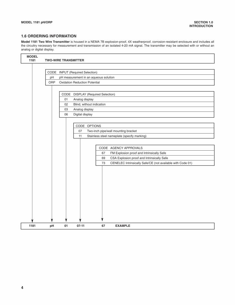
MODEL1181 TWO-WIRE TRANSMITTER
CODE INPUT (Required Selection)
pH pH measurement in an aqueous solution
ORP Oxidation Reduction Potential
CODE DISPLAY (Required Selection)
01 Analog display
02 Blind, without indication
03 Analog display
06 Digital display
CODE OPTIONS
07 Two-inch pipe/wall mounting bracket
11 Stainless steel nameplate (specify marking)
CODE AGENCY APPROVALS
67 FM Explosion proof and Intrinsically Safe
69 CSA Explosion proof and Intrinsically Safe
73 CENELEC Intrinsically Safe/CE (not available with Code 01)
1181 pH 01 07-11 67 EXAMPLE
1.6 ORDERING INFORMATIONModel 1181 Two Wire Transmitter is housed in a NEMA 7B explosion-proof, 4X weatherproof, corrosion-resistant enclosure and includes allthe circuitry necessary for measurement and transmission of an isolated 4-20 mA signal. The transmitter may be selected with or without ananalog or digital display.
5
MODEL 1181 pH/ORP SECTION 2.0INSTALLATION
SECTION 2.0INSTALLATION
2.1 GENERAL. The transmitter may be installed inharsh environmental locations. The transmitter should,however, be located to minimize the effects of temper-ature gradients and temperature fluctuations, and toavoid vibration and shock.
CAUTIONAVOID GROUND LOOPS:(Sensor's shieldwire must not contact a grounded surface).
1. Use well insulated wire. Clean up allmetal burrs on conduit before pullingcable.
2. Follow wiring instructions for the sen-sor. Shields aren't grounded on ouranalyzers.
3. Seal the sensor conduit from liquids,which can cause a short.
NOTEIntrinsically safe units must be installed inaccordance with their designated drawingnumbers. See Section 2.5 for details.Further non-certified components CAN-NOT be substituted with certified units.This would void all certifications.
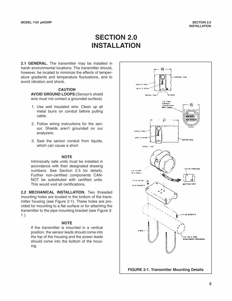
2.2 MECHANICAL INSTALLATION. Two threadedmounting holes are located in the bottom of the trans-mitter housing (see Figure 2-1). These holes are pro-vided for mounting to a flat surface or for attaching thetransmitter to the pipe mounting bracket (see Figure 2-1 ).
NOTEIf the transmitter is mounted in a verticalposition, the sensor leads should come intothe top of the housing and the power leadsshould come into the bottom of the hous-ing.
FIGURE 2-1. Transmitter Mounting Details
6
MODEL 1181 pH/ORP SECTION 2.0INSTALLATION
2.3 ELECTRICAL INSTALLATION. The transmitterhas two ¼-inch conduit openings, one on each side ofthe housing. One opening is for the power or signalwiring, and the other is for the input wiring from thesensor.
NOTEOn models with the meter, make sure themeter wiring is securely connected afterthe signal and input wiring have beenattached.
2.3.1 Sensor input wiring terminals are located on theside of the housing designated TERM SIDE on theserial label, and are the lower set of terminals (TB2).Remove the end cap from the TERM SIDE of the hous-ing to gain access to the terminals (see Figure 2-2).
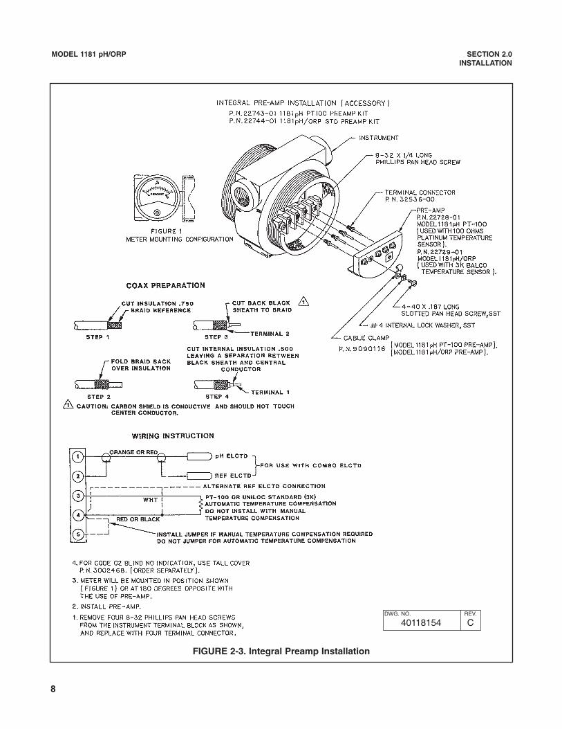
If the Model1181pH/ORP transmitter has been sup-plied with an integral preamplifier (Code PreampOptions 43 or 44), please refer to Figure 2-3 IntegralPreamp Installation, and Figure 2-4 Wiring DetailsIntegral Preamp for sensor input wiring instructions.
2.3.2 Power and signal wiring terminals are locateddirectly above the sensor input wiring terminals andare designated TBl. For models with a meter, the ter-minals leads are also attached to TBl.
2.3.3. Conduit connection on the transmitter housingshould be sealed or plugged (using a sealing com-pound) to avoid accumulation of moisture in housing. Ifthe connections are not sealed, the transmitter shouldbe mounted with the electrical housing downward fordraining.
2.3.4. The transmitter case shall be grounded. Powersupply regulation is not critical. Even with the powersupply ripple, of one volt peak to peak, the ripple in theoutput signal would be negligible.
NOTEFor best EMI/RFI protection, the power sup-ply/signal cable must be shielded and placedin an earth grounded, rigid metal conduit.Connect the outer shield to the earth groundterminal provided next to TB1.
The sensor cable should also be shielded.Connect the sensor cable’s outer shield to thetransmitter’s earth ground via the ground ter-minal next to TB1. If the sensor cable’s outershield is braided an appropriate metal cablegland fitting may be used to connect the braidto earth ground via the instrument case.
A new addition to the suite of tests done toensure CE compliance is IEC 1000-4-5. This isa surge immunity test that simulates overvolt-ages due to switching and lightning transients.
In order to meet the requirements of this test,additional protection must be added to theinstrument in the form of a Transient Protectorsuch as the Rosemount Model 470D. This is a3½-inch tube with ½-inch MNPT threads onboth ends. Inside the tube are gas dischargeand zener diode devices to limit surges to thetransmitter from the current loop. No additionalprotection is needed on the sensor connec-tions.
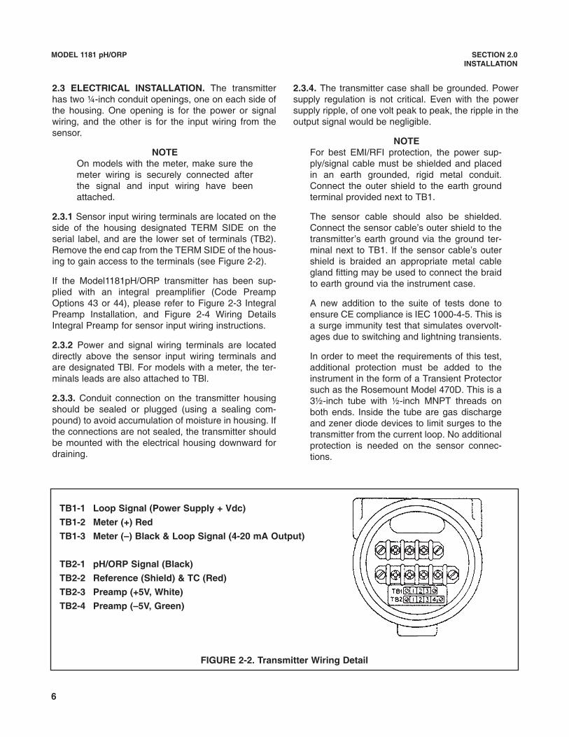
FIGURE 2-2. Transmitter Wiring Detail
TB1-1 Loop Signal (Power Supply + Vdc)
TB1-2 Meter (+) Red
TB1-3 Meter (–) Black & Loop Signal (4-20 mA Output)
TB2-1 pH/ORP Signal (Black)
TB2-2 Reference (Shield) & TC (Red)
TB2-3 Preamp (+5V, White)
TB2-4 Preamp (–5V, Green)
7
MODEL 1181 pH/ORP SECTION 2.0INSTALLATION
2.4 HAZARDOUS LOCATIONS-EXPLOSION PROOFINSTALLATIONS. In order to maintain the explosionproof rating for installed transmitter, the following con-ditions must be met.
1. The transmitter enclosure covers must be on handtight and the threads must not be damaged.
NOTEThese covers seat on rings which serve toprovide a dust proof enclosure for Class IIand Class III installations.
2. Explosion proof "Y" fittings must be properlyinstalled and plugged with a sealing compound toprevent explosive gases from entering the trans-mitter. CSA has determined that the transmitterhousing is "Factory Sealed". Installation of "Y" fit-tings and the use of sealing compound is notrequired for CSA approved Explosion Proof instal-lations.
NOTEDo not install sealing compound until allfield wiring is completed.
CAUTIONSealing compound must be installed priorto applying power to the transmitter.
3. If one of the conduit connections on the housing isnot used, it must be closed with a threaded metalplug with at least five threads engaged.
4. The serial tag cover on the external ZERO andSPAN adjustments must be in place.
6. Explosion proof installation must be in accordancewith Drawing Number 1400155 (see Figure 2-12).
5. For sensors in hazardous area locations, explo-sion proof junction boxes can be provided tohouse the preamplifier. This does not warrant thepH or ORP sensor explosion-proof. Maximumsafety can be achieved by installing an intrinsicallysafe system where Hazardous Area requirementsmust be met.
2.5 HAZARD LOCATIONS - INTRINSICALLY SAFEINSTALLATIONS. To secure and maintain intrinsicallysafe installations for the appropriate approval agency,the following conditions must be met:
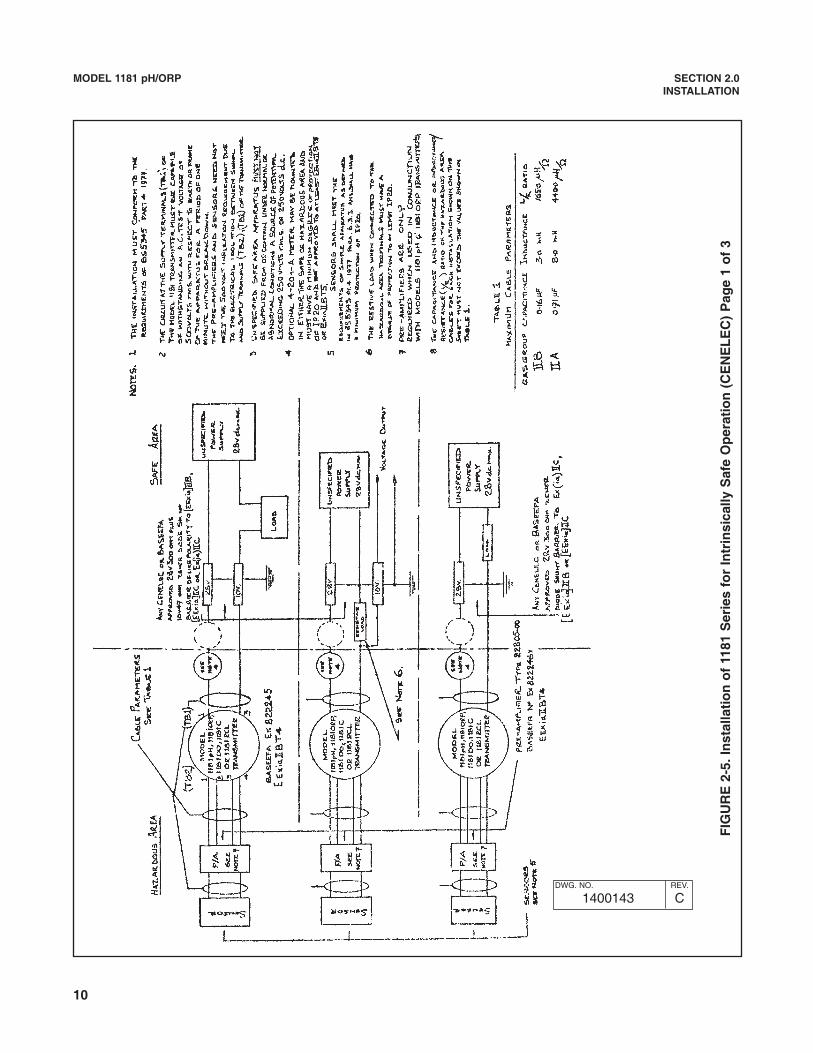
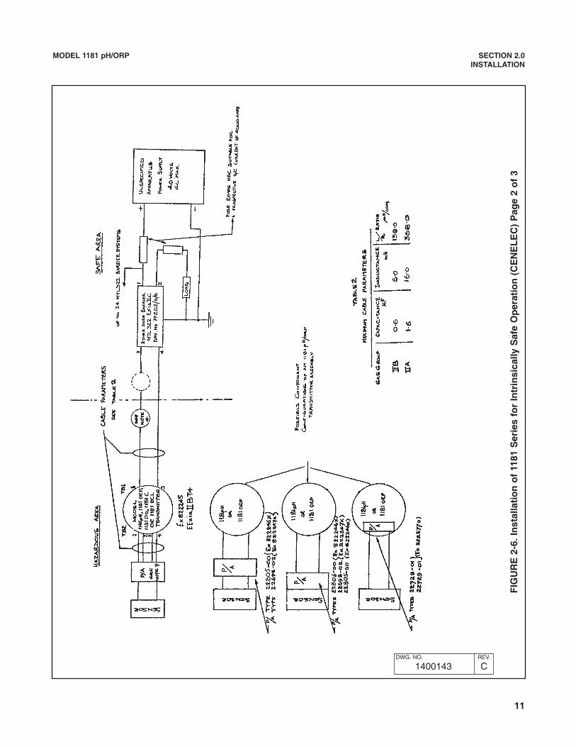
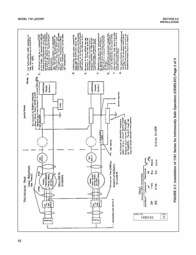
1. Code 73 must be specified when ordering CEN-ELEC/BASEEFA units. Installation must be per-formed in accordance with Drawing Number1400143 (see Figures 2-5, 6 & 7).
2. Code 69 must be specified when ordering C.S.A.(Canadian Standards Association) units.Installation must be in accordance with DrawingNumber 1400123 (see Figure 2-8).
3. Code 67 must be specified when ordering F.M.(Factory Mutual) units. Approved “Entity” installa-tion must be in accordance with Drawing Number1400153 (see Figures 2-9, 2-10, and 2-11).
8
MODEL 1181 pH/ORP SECTION 2.0INSTALLATION
FIGURE 2-3. Integral Preamp Installation
DWG. NO. REV.
40118154 C

9
MODEL 1181 pH/ORP SECTION 2.0INSTALLATION
FIGURE 2-4. Wiring Details Integral Preamp
DWG. NO. REV.
40118119 C
10
MODEL 1181 pH/ORP SECTION 2.0INSTALLATION
FIG
UR
E 2
-5. I
nst
alla
tio
n o
f 11
81 S
erie
s fo
r In
trin
sica
lly S
afe
Op
erat
ion
(C
EN
EL
EC
) P
age
1 o
f 3
DWG. NO. REV.
1400143 C
11
MODEL 1181 pH/ORP SECTION 2.0INSTALLATION
FIG
UR
E 2
-6. I
nst
alla
tio
n o
f 11
81 S
erie
s fo
r In
trin
sica
lly S
afe
Op
erat
ion
(C
EN
EL
EC
) P
age
2 o
f 3
DWG. NO. REV.
1400143 C
12
MODEL 1181 pH/ORP SECTION 2.0INSTALLATION
FIG
UR
E 2
-7. I
nst
alla
tio
n o
f 11
81 S
erie
s fo
r In
trin
sica
lly S
afe
Op
erat
ion
(C
EN
EL
EC
) P
age
3 o
f 3
DWG. NO. REV.
1400143 C
13
MODEL 1181 pH/ORP SECTION 2.0INSTALLATION
FIG
UR
E 2
-8. S
chem
atic
, Sys
tem
118
1 p
H &
OR
P, C
SA
DWG. NO. REV.
1400123 E
14
MODEL 1181 pH/ORP SECTION 2.0INSTALLATION
FIG
UR
E 2
-9. 1
181
Sch
emat
ic, S
yste
m F
.M. I
.S. A
pp
rove
d -
En
tity
Pag
e 1
of
3
DWG. NO. REV.
1400153 D
15
MODEL 1181 pH/ORP SECTION 2.0INSTALLATION
FIG
UR
E 2
-10.
118
1 S
chem
atic
, Sys
tem
F.M
. I.S
. Ap
pro
ved
- E
nti
ty P
age
2 o
f 3
DWG. NO. REV.
1400153 D
16
MODEL 1181 pH/ORP SECTION 2.0INSTALLATION
FIG
UR
E 2
-11.
118
1 S
chem
atic
, Sys
tem
F.M
. I.S
. Ap
pro
ved
- E
nti
ty P
age
3 o
f 3
DWG. NO. REV.
1400153 D

17
MODEL 1181 pH/ORP SECTION 2.0INSTALLATION
FIG
UR
E 2
-12.
118
1 S
chem
atic
, Sys
tem
F.M
. E.P
. Ap
pro
ved
DWG. NO. REV.
1400155 C
18
MODEL 1181pH/ORP SECTION 3.0START UP, AND CALIBRATION
SECTION 3.0START UP AND CALIBRATION
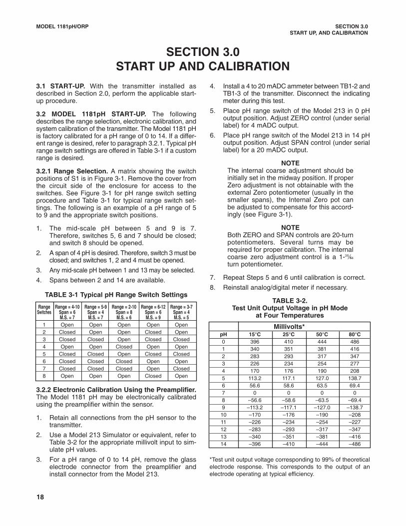
3.1 START-UP. With the transmitter installed asdescribed in Section 2.0, perform the applicable start-up procedure.
3.2 MODEL 1181pH START-UP. The followingdescribes the range selection, electronic calibration, andsystem calibration of the transmitter. The Model 1181 pHis factory calibrated for a pH range of 0 to 14. If a differ-ent range is desired, refer to paragraph 3.2.1. Typical pHrange switch settings are offered in Table 3-1 if a customrange is desired.
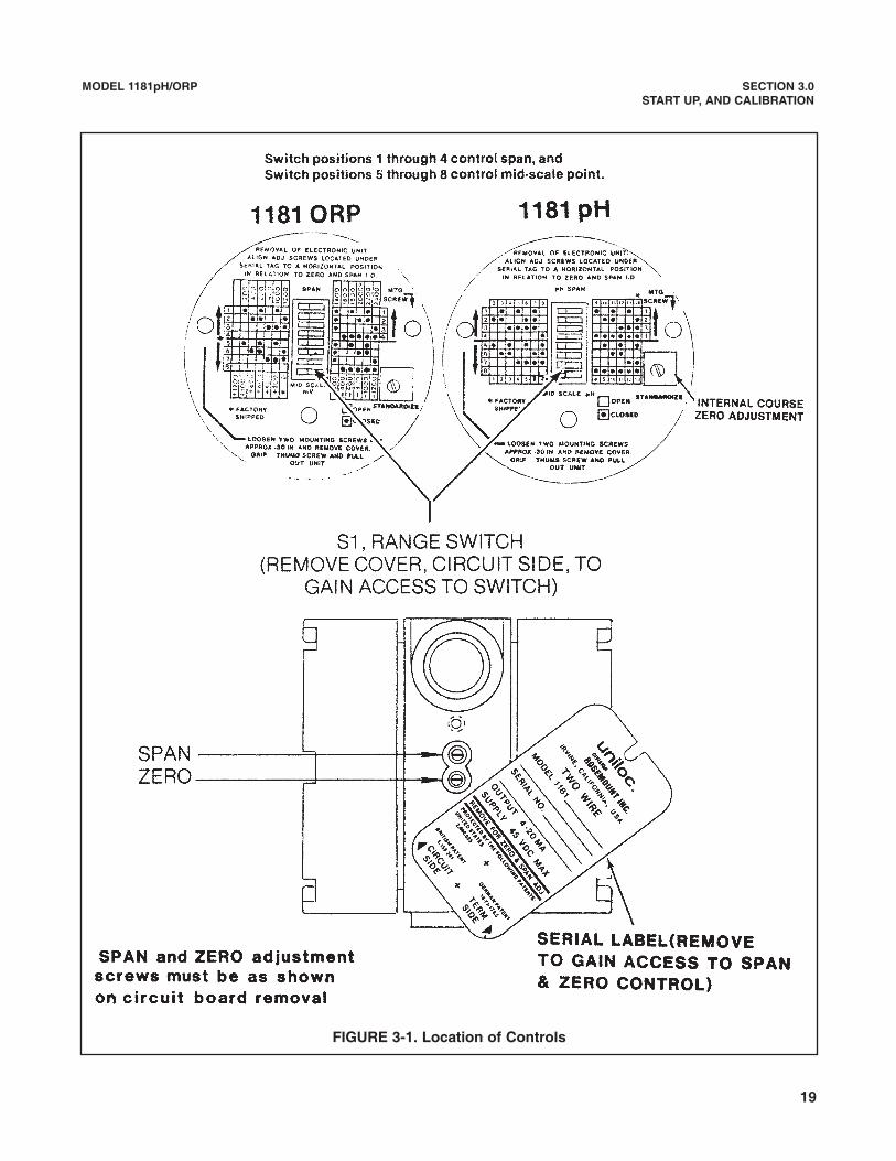
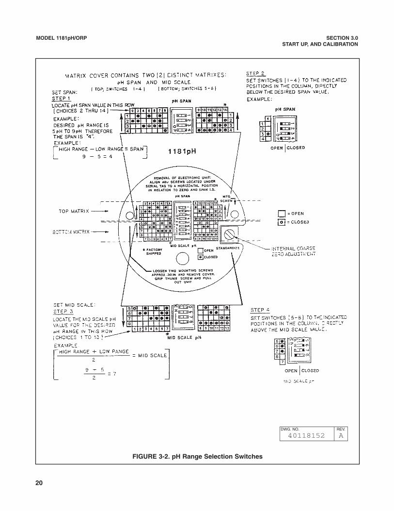
3.2.1 Range Selection. A matrix showing the switchpositions of S1 is in Figure 3-1. Remove the cover fromthe circuit side of the enclosure for access to theswitches. See Figure 3-1 for pH range switch settingprocedure and Table 3-1 for typical range switch set-tings. The following is an example of a pH range of 5to 9 and the appropriate switch positions.
1. The mid-scale pH between 5 and 9 is 7.Therefore, switches 5, 6 and 7 should be closed;and switch 8 should be opened.
2. A span of 4 pH is desired. Therefore, switch 3 must beclosed; and switches 1, 2 and 4 must be opened.
3. Any mid-scale pH between 1 and 13 may be selected.
4. Spans between 2 and 14 are available.
TABLE 3-1 Typical pH Range Switch Settings
3.2.2 Electronic Calibration Using the Preamplifier.The Model 1181 pH may be electronically calibratedusing the preamplifier within the sensor.
1. Retain all connections from the pH sensor to thetransmitter.
2. Use a Model 213 Simulator or equivalent, refer toTable 3-2 for the appropriate millivolt input to sim-ulate pH values.
3. For a pH range of 0 to 14 pH, remove the glasselectrode connector from the preamplifier andinstall connector from the Model 213.
4. Install a 4 to 20 mADC ammeter between TB1-2 andTB1-3 of the transmitter. Disconnect the indicatingmeter during this test.
5. Place pH range switch of the Model 213 in 0 pHoutput position. Adjust ZERO control (under seriallabel) for 4 mADC output.
6. Place pH range switch of the Model 213 in 14 pHoutput position. Adjust SPAN control (under seriallabel) for a 20 mADC output.
NOTEThe internal coarse adjustment should beinitially set in the midway position. If properZero adjustment is not obtainable with theexternal Zero potentiometer (usually in thesmaller spans), the Internal Zero pot canbe adjusted to compensate for this accord-ingly (see Figure 3-1).
NOTEBoth ZERO and SPAN controls are 20-turnpotentiometers. Several turns may berequired for proper calibration. The internalcoarse zero adjustment control is a 1-3¼4
turn potentiometer.
7. Repeat Steps 5 and 6 until calibration is correct.
8. Reinstall analog/digital meter if necessary.
TABLE 3-2.Test Unit Output Voltage in pH Mode
at Four Temperatures
*Test unit output voltage corresponding to 99% of theoreticalelectrode response. This corresponds to the output of anelectrode operating at typical efficiency.
Millivolts*pH 15°C 25°C 50°C 80°C0 396 410 444 4861 340 351 381 4162 283 293 317 3473 226 234 254 2774 170 176 190 2085 113.2 117.1 127.0 138.76 56.6 58.6 63.5 69.47 0 0 0 08 –56.6 –58.6 –63.5 –69.49 –113.2 –117.1 –127.0 –138.7
10 –170 –176 –190 –20811 –226 –234 –254 –22712 –283 –293 –317 –34713 –340 –351 –381 –41614 –396 –410 –444 –486
Range Range = 4-10 Range = 5-9 Range = 2-10 Range = 6-12 Range = 3-7Switches Span = 6 Span = 4 Span = 8 Span = 6 Span = 4
M.S. = 7 M.S. = 7 M.S. = 6 M.S. = 9 M.S. = 51 Open Open Open Open Open2 Closed Open Open Closed Open3 Closed Closed Open Closed Closed4 Open Open Closed Open Open5 Closed Closed Open Closed Closed6 Closed Closed Closed Open Open7 Closed Closed Closed Open Closed8 Open Open Open Closed Open
19
MODEL 1181pH/ORP SECTION 3.0START UP, AND CALIBRATION
FIGURE 3-1. Location of Controls
20
MODEL 1181pH/ORP SECTION 3.0START UP, AND CALIBRATION
FIGURE 3-2. pH Range Selection Switches
DWG. NO. REV.
40118152 A
21
MODEL 1181pH/ORP SECTION 3.0START UP, AND CALIBRATION
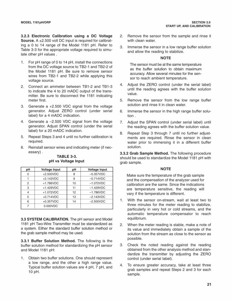
3.2.3 Electronic Calibration using a DC VoltageSource. A ±2.500 volt DC input is required for calibrat-ing a 0 to 14 range of the Model 1181 pH. Refer toTable 3-3 for the appropriate voltage required to simu-late other pH values .
1. For pH range of 0 to 14 pH, install the connectionsfrom the DC voltage source to TB2-1 and TB2-2 ofthe Model 1181 pH. Be sure to remove sensorwires from TB2-1 and TB2-2 while applying thisvoltage source.
2. Connect an ammeter between TB1-2 and TB1-3to indicate the 4 to 20 mADC output of the trans-mitter. Be sure to disconnect the 1181 indicatingmeter first.
3. Generate a +2.500 VDC signal from the voltagegenerator. Adjust ZERO control (under seriallabel) for a 4 mADC indication.
4. Generate a –2.500 VDC signal from the voltagegenerator. Adjust SPAN control (under the seriallabel) for a 20 mADC indication.
5. Repeat Steps 3 and 4 until no further calibration isrequired.
6. Reinstall sensor wires and indicating meter (if nec-essary) .
TABLE 3-3.pH vs Voltage Input
3.3 SYSTEM CALIBRATION. The pH sensor and Model1181 pH Two-Wire Transmitter must be standardized asa system. Either the standard buffer solution method orthe grab sample method may be used.
3.3.1 Buffer Solution Method. The following is thebuffer solution method for standardizing the pH sensorand Model 1181 pH:
1. Obtain two buffer solutions. One should representa low range, and the other a high range value.Typical buffer solution values are 4 pH, 7 pH, and10 pH.
2. Remove the sensor from the sample and rinse itwith clean water.
3. Immerse the sensor in a low range buffer solutionand allow the reading to stabilize.
NOTE
The sensor must be at the same temperatureas the buffer solution to obtain maximumaccuracy. Allow several minutes for the sen-sor to reach ambient temperature.
4. Adjust the ZERO control (under the serial label)until the reading agrees with the buffer solutionvalue.
5. Remove the sensor from the low range buffersolution and rinse it in clean water.
6. Immerse the sensor in the high range buffer solu-tion .
7. Adjust the SPAN control (under serial label) untilthe reading agrees with the buffer solution value.
8. Repeat Step 3 through 7 until no further adjust-ments are required. Rinse the sensor in cleanwater prior to immersing it in a different buffersolution.
3.3.2 Grab Sample Method. The following procedureshould be used to standardize the Model 1181 pH withgrab sample.
NOTE
Make sure the temperature of the grab sampleand the compensation of the analyzer used forcalibration are the same. Since the indicationsare temperature sensitive, the reading willvary if the temperature is different.
1. With the sensor on-stream, wait at least two tothree minutes for the meter reading to stabilize,particularly in very hot or cold streams, and theautomatic temperature compensator to reachequilibrium.
2. When the meter reading is stable, make a note ofits value and immediately obtain a sample of thesolution from the stream as close to the sensor aspossible.
3. Check the noted reading against the readingobtained from the other analysis method and stan-dardize the transmitter by adjusting the ZEROcontrol (under serial label).
4. To ensure greater accuracy, take at least threegrab samples and repeat Steps 2 and 3 for eachsample.
pH Voltage Input pH Voltage Input
0 +2.500VDC 8 –0.357VDC
1 +2.143VDC 9 –0.714VDC
2 +1.786VDC 10 –1.072VDC
3 +1.429VDC 11 –1.429VDC
4 +1.072VDC 12 –1.786VDC
5 +0.714VDC 13 –2.143VDC
6 +0.357VDC 14 –2.500VDC
7 0.000VDC
22
MODEL 1181pH/ORP SECTION 3.0START UP, AND CALIBRATION
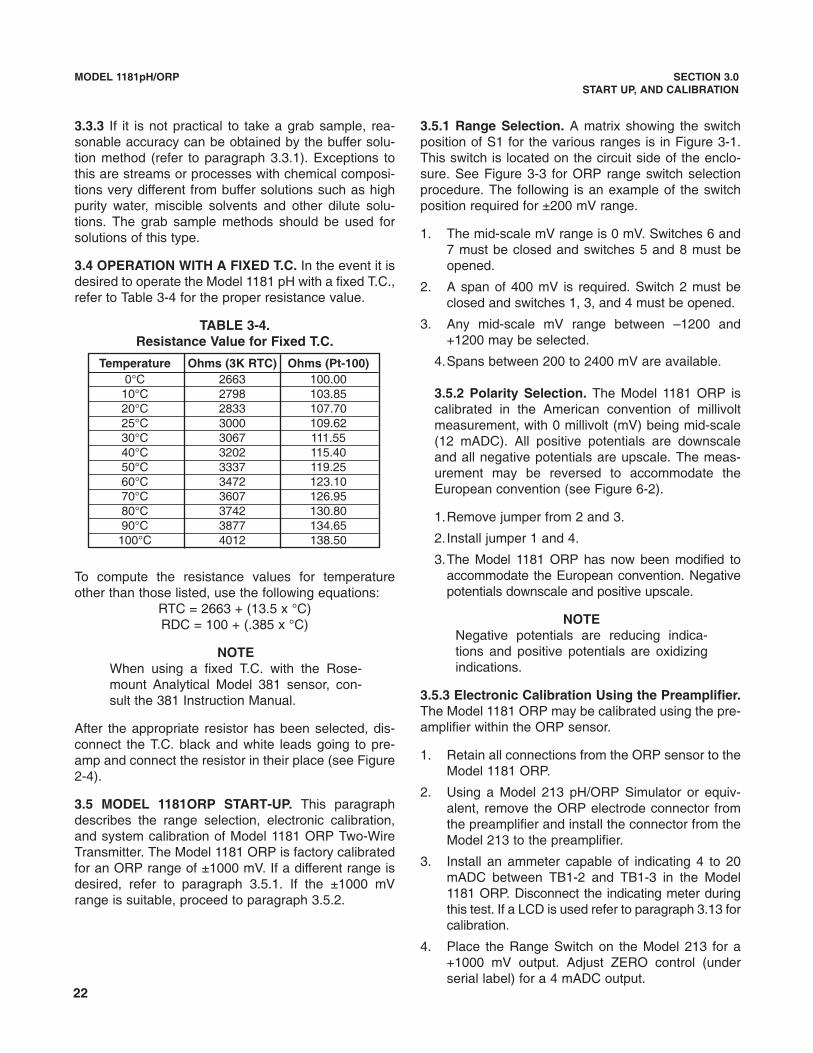
3.3.3 If it is not practical to take a grab sample, rea-sonable accuracy can be obtained by the buffer solu-tion method (refer to paragraph 3.3.1). Exceptions tothis are streams or processes with chemical composi-tions very different from buffer solutions such as highpurity water, miscible solvents and other dilute solu-tions. The grab sample methods should be used forsolutions of this type.
3.4 OPERATION WITH A FIXED T.C. In the event it isdesired to operate the Model 1181 pH with a fixed T.C.,refer to Table 3-4 for the proper resistance value.
TABLE 3-4.Resistance Value for Fixed T.C.
To compute the resistance values for temperatureother than those listed, use the following equations:
RTC = 2663 + (13.5 x °C)RDC = 100 + (.385 x °C)
NOTEWhen using a fixed T.C. with the Rose-mount Analytical Model 381 sensor, con-sult the 381 Instruction Manual.
After the appropriate resistor has been selected, dis-connect the T.C. black and white leads going to pre-amp and connect the resistor in their place (see Figure2-4).
3.5 MODEL 1181ORP START-UP. This paragraphdescribes the range selection, electronic calibration,and system calibration of Model 1181 ORP Two-WireTransmitter. The Model 1181 ORP is factory calibratedfor an ORP range of ±1000 mV. If a different range isdesired, refer to paragraph 3.5.1. If the ±1000 mVrange is suitable, proceed to paragraph 3.5.2.
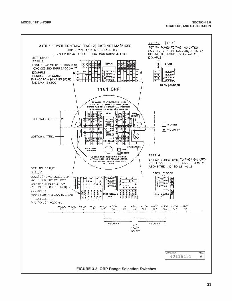
3.5.1 Range Selection. A matrix showing the switchposition of S1 for the various ranges is in Figure 3-1.This switch is located on the circuit side of the enclo-sure. See Figure 3-3 for ORP range switch selectionprocedure. The following is an example of the switchposition required for ±200 mV range.
1. The mid-scale mV range is 0 mV. Switches 6 and7 must be closed and switches 5 and 8 must beopened.
2. A span of 400 mV is required. Switch 2 must beclosed and switches 1, 3, and 4 must be opened.
3. Any mid-scale mV range between –1200 and+1200 may be selected.
4.Spans between 200 to 2400 mV are available.
3.5.2 Polarity Selection. The Model 1181 ORP iscalibrated in the American convention of millivoltmeasurement, with 0 millivolt (mV) being mid-scale(12 mADC). All positive potentials are downscaleand all negative potentials are upscale. The meas-urement may be reversed to accommodate theEuropean convention (see Figure 6-2).
1.Remove jumper from 2 and 3.
2.Install jumper 1 and 4.
3.The Model 1181 ORP has now been modified toaccommodate the European convention. Negativepotentials downscale and positive upscale.
NOTENegative potentials are reducing indica-tions and positive potentials are oxidizingindications.
3.5.3 Electronic Calibration Using the Preamplifier.The Model 1181 ORP may be calibrated using the pre-amplifier within the ORP sensor.
1. Retain all connections from the ORP sensor to theModel 1181 ORP.
2. Using a Model 213 pH/ORP Simulator or equiv-alent, remove the ORP electrode connector fromthe preamplifier and install the connector from theModel 213 to the preamplifier.
3. Install an ammeter capable of indicating 4 to 20mADC between TB1-2 and TB1-3 in the Model1181 ORP. Disconnect the indicating meter duringthis test. If a LCD is used refer to paragraph 3.13 forcalibration.
4. Place the Range Switch on the Model 213 for a+1000 mV output. Adjust ZERO control (underserial label) for a 4 mADC output.
Temperature Ohms (3K RTC) Ohms (Pt-100)0°C 2663 100.00
10°C 2798 103.8520°C 2833 107.7025°C 3000 109.6230°C 3067 111.5540°C 3202 115.4050°C 3337 119.2560°C 3472 123.1070°C 3607 126.9580°C 3742 130.8090°C 3877 134.65
100°C 4012 138.50
23
MODEL 1181pH/ORP SECTION 3.0START UP, AND CALIBRATION
FIGURE 3-3. ORP Range Selection Switches
DWG. NO. REV.
40118151 A
24
NOTEBoth ZERO and SPAN Controls are 20 turnpotentiometers. Several turns may berequired for proper calibration.
5. Generate a –1.000 VDC signal from the voltagesource. Adjust span control (under serial label) fora 20 mADC output.
6. Repeat Steps 4 and 5 until calibration is correct.
3.5.4 Electronic Calibration Using a DC VoltageSource. An output up to ±1.000 VDC is required as aninput to the 1181 ORP. Refer to Table 3-5 for the appro-priate voltage required to simulate desired mV values.
NOTEVoltage listed are the American Con-vention, reverse polarity for European Con-vention.
TABLE 3-5.Millivolt vs. Voltage Input
The following calibration procedure is for a ±1000 mVrange.
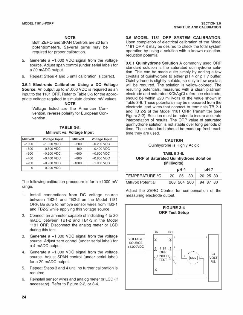
1. Install connections from DC voltage sourcebetween TB2-1 and TB2-2 on the Model 1181ORP. Be sure to remove sensor wires from TB2-1and TB2-2 while applying this voltage source.
2. Connect an ammeter capable of indicating 4 to 20mADC between TB1-2 and TB1-3 in the Model1181 ORP. Disconnect the analog meter or LCDduring this test.
3. Generate a +1.000 VDC signal from the voltagesource. Adjust zero control (under serial label) fora 4 mADC output.
4. Generate a –1.000 VDC signal from the voltagesource. Adjust SPAN control (under serial label)for a 20 mADC output.
5. Repeat Steps 3 and 4 until no further calibration isrequired.
6. Reinstall sensor wires and analog meter or LCD (ifnecessary). Refer to Figure 2-2, or 3-4.
MODEL 1181pH/ORP SECTION 3.0START UP, AND CALIBRATION
3.6 MODEL 1181 ORP SYSTEM CALIBRATION.Upon completion of electrical calibration of the Model1181 ORP, it may be desired to check the total systemoperation by using a solution with a known oxidation-reduction potential.
3.6.1 Quinhydrone Solution A commonly used ORPstandard solution is the saturated quinhydrone solu-tion. This can be made quite simply by adding a fewcrystals of quinhydrone to either pH 4 or pH 7 buffer.Quinhydrone is slightly soluble, so only a few crystalswill be required. The solution is yellow-colored. Theresulting potentials, measured with a clean platinumelectrode and saturated KCl/AgCI reference electrode,should be within ±20 millivolts of the value shown inTable 3-6. These potentials may be measured from theelectrode lead wires that connect to terminals TB 2-1and TB 2-2 of the Model 1181 ORP Transmitter (seeFigure 2-2). Solution must be noted to insure accurateinterpretation of results. The ORP value of saturatedquinhydrone solution is not stable over long periods oftime. These standards should be made up fresh eachtime they are used.
CAUTIONQuinhydrone is Highly Acidic
TABLE 3-6.ORP of Saturated Quinhydrone Solution
(Millivolts)
pH 4 pH 7
TEMPERATURE °C 20 25 30 20 25 30
Millivolt Potential 268 264 260 94 87 80
Adjust the ZERO Control for compensation of themeasuring electrode output.
Millivolt Voltage Input Millivolt Voltage Input
+1000 +1.000 VDC –200 –0.200 VDC
+800 +0.800 VDC –400 –0.400 VDC
+600 +0.600 VDC –600 –0.600 VDC
+400 +0.400 VDC –800 –0.800 VDC
+200 +0.200 VDC –1000 –1.000 VDC
0 0.000 VDC
FIGURE 3-4ORP Test Setup
VOLTAGESOURCE
±1.000VDC
24VOLTP.S.
1181ORP
UNDERTEST
1 1
2 2
33
4
+
+
+- -
TB1TB2
+
-
DMV
25
MODEL 1181pH/ORP SECTION 3.0START UP, AND CALIBRATION
3.6.2 Ferric-Ferrous Ammonium Sulfate Test.Although this standard ORP solution is not as easy toprepare as the quinhydrone solution in Section 3.6.1, itoffers a much more stable solution which will maintainits millivolt value for approximately one year whenstored in glass containers.
Dissolve 39.2 grams of reagent grade ferrous ammo-nium sulfate [Fe (NH4)2(SO4)2 • 6H20] and 48.2grams of reagent grade ferric ammonium sulfate[F2NH4(SO4)2 12H20] in approximately 700 millilitersof water (distilled water is preferred, but tap water isacceptable). Slowly and carefully add 56.2 milliliters ofconcentrated sulfuric acid. Add sufficient water to bringthe total solution volume up to 1,000 milliliters. Thissolution (ferric-ferrous ammonium sulfate) will producea nominal ORP of 476 ±20 mV at 25°C when used witha saturated KCl/AgCI reference electrode (or 430 mVwith a Calomel reference electrode) and platinummeasuring electrode. The above potentials may bemeasured from the electrode lead wires that connect toTB 2-1 and TB 2-2 of the Model 1181 ORP Transmitter(see Figure 2-2).Some tolerance in mV values is to beexpected due to the rather large liquid reference junc-tion potentials which can arise when measuring thisstrongly acidic and concentrated solution. However, ifthe measuring electrodes are kept clean and in goodoperating condition, consistent repeatable calibrationscan be achieved.
3.7 OPERATING WITH INTEGRAL PREAMP(ACCESSORY). The preamp may be ordered as anaccessory to the Model 1181 pH/ORP. This enablesthe user to mount the preamp integral to the Model1181 pH/ORP. This will eliminate the use of a junctionbox when remote preamps are required.
This preamp is applicable to explosion-proof (Class 1,Group C and D, Div. 1) installations and to applicationswhere the preamp must be remote from the sensor dueto high temperatures (above 80°C).
Two types of preamps are available. P/N 22744-01 iscompatible with a 3K RTD. P/N 22743-01 is compati-ble with a 100 ohm RTD.
Please refer to Figure 2-3 for installation instructions.The user must remove the BNC electrode connectorfrom the coax cable supplied with the sensor and pre-pare the coax as shown in Figure 2-4.
Due to space limitations the meter mounting position isrestricted (see insert, Figure 2-3). Additionally, the inte-gral preamp accessory must be used with the analogmeter (Code 01 or Code 03) option, or with the LCDindication (Code 06) option. In order to use the integralpreamp accessory with blind transmitters (Code 02),P/N 3002468 (tall cover) must be ordered as a sparepart. The integral preamp accessory is not availablewith LCD indication (Code 04) option.
NOTEThe maximum distance between the Model1181 pH/ORP with an integral preamp andthe sensor is 15 feet (4.5m).
The Model 1181 pH/ORP with integral preamp shouldnot be used with a ruggedized pH electrode at operat-ing temperatures of less than 25°C (77°F).
26
MODEL 1181pH/ORP SECTION 3.0START UP, AND CALIBRATION
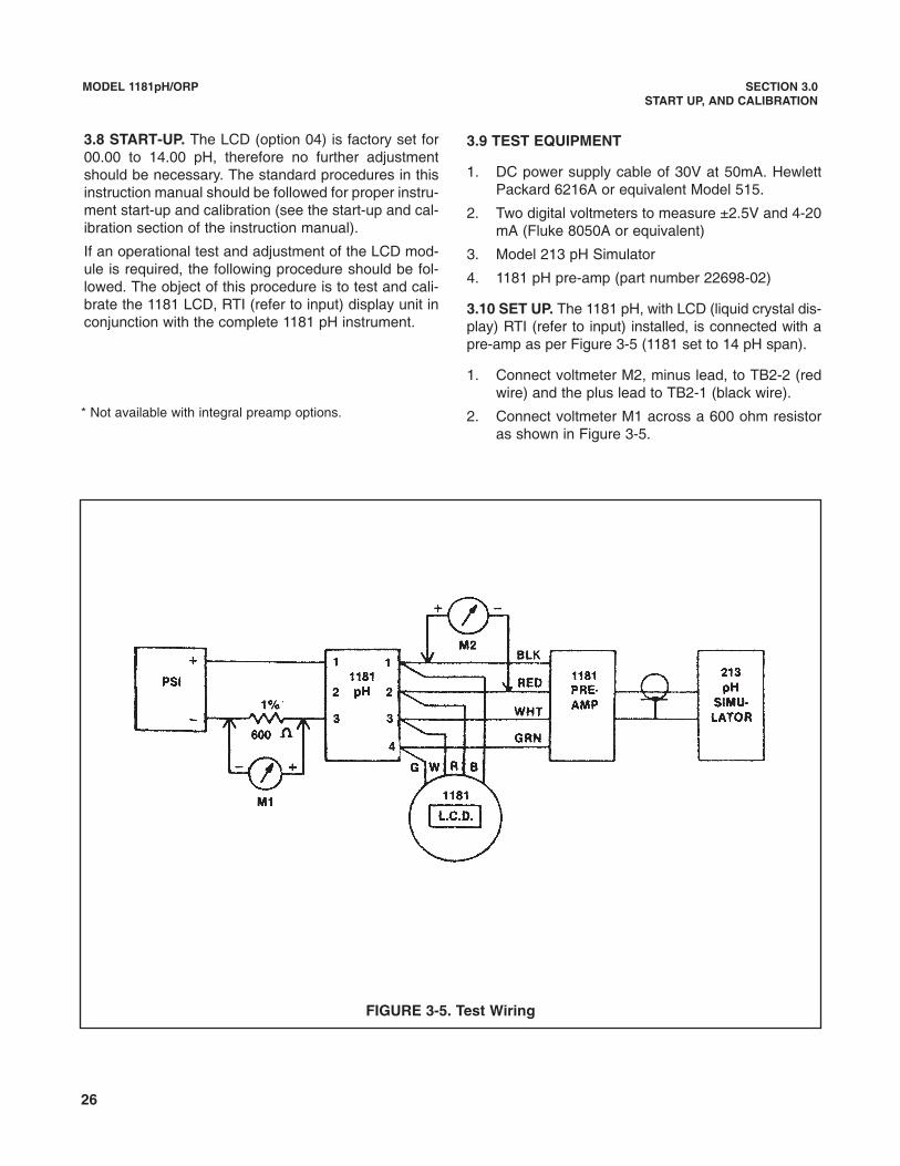
3.8 START-UP. The LCD (option 04) is factory set for00.00 to 14.00 pH, therefore no further adjustmentshould be necessary. The standard procedures in thisinstruction manual should be followed for proper instru-ment start-up and calibration (see the start-up and cal-ibration section of the instruction manual).
If an operational test and adjustment of the LCD mod-ule is required, the following procedure should be fol-lowed. The object of this procedure is to test and cali-brate the 1181 LCD, RTI (refer to input) display unit inconjunction with the complete 1181 pH instrument.
FIGURE 3-5. Test Wiring
* Not available with integral preamp options.
3.9 TEST EQUIPMENT
1. DC power supply cable of 30V at 50mA. HewlettPackard 6216A or equivalent Model 515.
2. Two digital voltmeters to measure ±2.5V and 4-20mA (Fluke 8050A or equivalent)
3. Model 213 pH Simulator
4. 1181 pH pre-amp (part number 22698-02)
3.10 SET UP. The 1181 pH, with LCD (liquid crystal dis-play) RTI (refer to input) installed, is connected with apre-amp as per Figure 3-5 (1181 set to 14 pH span).
1. Connect voltmeter M2, minus lead, to TB2-2 (redwire) and the plus lead to TB2-1 (black wire).
2. Connect voltmeter M1 across a 600 ohm resistoras shown in Figure 3-5.
27
MODEL 1181pH/ORP SECTION 3.0START UP, AND CALIBRATION
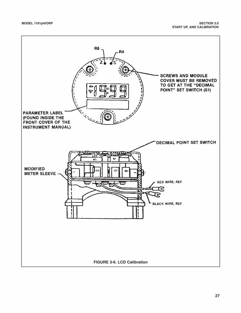
FIGURE 3-6. LCD Calibration
28
MODEL 1181pH/ORP SECTION 3.0START UP, AND CALIBRATION
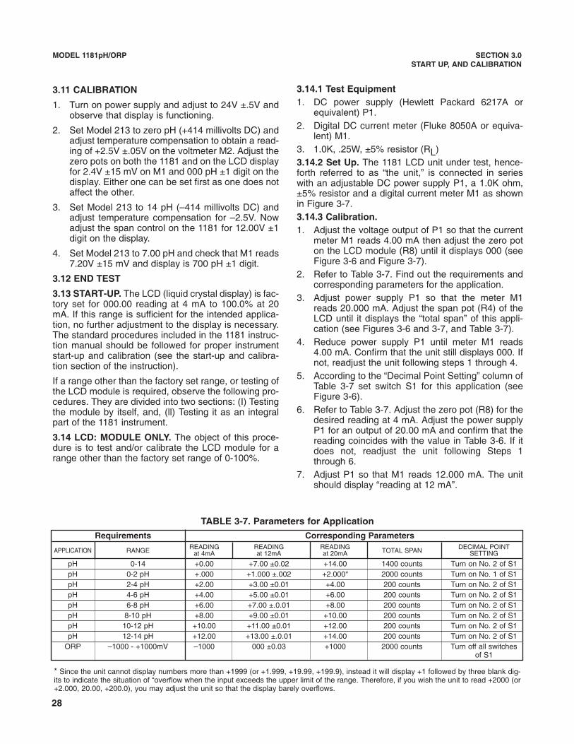
* Since the unit cannot display numbers more than +1999 (or +1.999, +19.99, +199.9), instead it will display +1 followed by three blank dig-its to indicate the situation of “overflow when the input exceeds the upper limit of the range. Therefore, if you wish the unit to read +2000 (or+2.000, 20.00, +200.0), you may adjust the unit so that the display barely overflows.
Requirements Corresponding ParametersREADING READING READING DECIMAL POINTAPPLICATION RANGE at 4mA at 12mA at 20mA TOTAL SPAN SETTING
pH 0-14 +0.00 +7.00 ±0.02 +14.00 1400 counts Turn on No. 2 of S1pH 0-2 pH +.000 +1.000 ±.002 +2.000* 2000 counts Turn on No. 1 of S1pH 2-4 pH +2.00 +3.00 ±0.01 +4.00 200 counts Turn on No. 2 of S1pH 4-6 pH +4.00 +5.00 ±0.01 +6.00 200 counts Turn on No. 2 of S1pH 6-8 pH +6.00 +7.00 ±.0.01 +8.00 200 counts Turn on No. 2 of S1pH 8-10 pH +8.00 +9.00 ±0.01 +10.00 200 counts Turn on No. 2 of S1pH 10-12 pH +10.00 +11.00 ±0.01 +12.00 200 counts Turn on No. 2 of S1pH 12-14 pH +12.00 +13.00 ±.0.01 +14.00 200 counts Turn on No. 2 of S1
ORP –1000 - +1000mV –1000 000 ±0.03 +1000 2000 counts Turn off all switchesof S1
3.11 CALIBRATION
1. Turn on power supply and adjust to 24V ±.5V andobserve that display is functioning.
2. Set Model 213 to zero pH (+414 millivolts DC) andadjust temperature compensation to obtain a read-ing of +2.5V ±.05V on the voltmeter M2. Adjust thezero pots on both the 1181 and on the LCD displayfor 2.4V ±15 mV on M1 and 000 pH ±1 digit on thedisplay. Either one can be set first as one does notaffect the other.
3. Set Model 213 to 14 pH (–414 millivolts DC) andadjust temperature compensation for –2.5V. Nowadjust the span control on the 1181 for 12.00V ±1digit on the display.
4. Set Model 213 to 7.00 pH and check that M1 reads7.20V ±15 mV and display is 700 pH ±1 digit.
3.12 END TEST
3.13 START-UP. The LCD (liquid crystal display) is fac-tory set for 000.00 reading at 4 mA to 100.0% at 20mA. If this range is sufficient for the intended applica-tion, no further adjustment to the display is necessary.The standard procedures included in the 1181 instruc-tion manual should be followed for proper instrumentstart-up and calibration (see the start-up and calibra-tion section of the instruction).
If a range other than the factory set range, or testing ofthe LCD module is required, observe the following pro-cedures. They are divided into two sections: (I) Testingthe module by itself, and, (ll) Testing it as an integralpart of the 1181 instrument.
3.14 LCD: MODULE ONLY. The object of this proce-dure is to test and/or calibrate the LCD module for arange other than the factory set range of 0-100%.
3.14.1 Test Equipment1. DC power supply (Hewlett Packard 6217A or
equivalent) P1.2. Digital DC current meter (Fluke 8050A or equiva-
lent) M1.3. 1.0K, .25W, ±5% resistor (RL)3.14.2 Set Up. The 1181 LCD unit under test, hence-forth referred to as “the unit,” is connected in serieswith an adjustable DC power supply P1, a 1.0K ohm,±5% resistor and a digital current meter M1 as shownin Figure 3-7.3.14.3 Calibration.1. Adjust the voltage output of P1 so that the current
meter M1 reads 4.00 mA then adjust the zero poton the LCD module (R8) until it displays 000 (seeFigure 3-6 and Figure 3-7).
2. Refer to Table 3-7. Find out the requirements andcorresponding parameters for the application.
3. Adjust power supply P1 so that the meter M1reads 20.000 mA. Adjust the span pot (R4) of theLCD until it displays the “total span” of this appli-cation (see Figures 3-6 and 3-7, and Table 3-7).
4. Reduce power supply P1 until meter M1 reads4.00 mA. Confirm that the unit still displays 000. Ifnot, readjust the unit following steps 1 through 4.
5. According to the “Decimal Point Setting” column ofTable 3-7 set switch S1 for this application (seeFigure 3-6).
6. Refer to Table 3-7. Adjust the zero pot (R8) for thedesired reading at 4 mA. Adjust the power supplyP1 for an output of 20.00 mA and confirm that thereading coincides with the value in Table 3-6. If itdoes not, readjust the unit following Steps 1through 6.
7. Adjust P1 so that M1 reads 12.000 mA. The unitshould display “reading at 12 mA”.
TABLE 3-7. Parameters for Application

29
MODEL 1181pH/ORP SECTION 3.0START UP, AND CALIBRATION
FIGURE 3-7. LCD Test Set Up Wiring
DWG. NO. REV.
40118160 B
30
MODEL 1181pH/ORP SECTION 3.0START UP, AND CALIBRATION
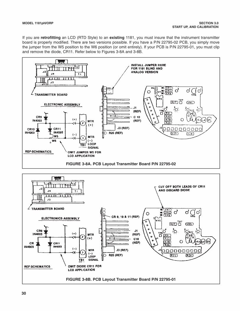
FIGURE 3-8A. PCB Layout Transmitter Board P/N 22795-02
FIGURE 3-8B. PCB Layout Transmitter Board P/N 22795-01
If you are retrofitting an LCD (RTD Style) to an existing 1181, you must insure that the instrument transmitterboard is properly modified. There are two versions possible. If you have a P/N 22795-02 PCB, you simply movethe jumper from the W5 position to the W6 position (or omit entirely). If your PCB is P/N 22795-01, you must clipand remove the diode, CR11. Refer below to Figures 3-8A and 3-8B.
31
MODEL 1181pH/ORP SECTION 4.0THEORY OF OPERATION
SECTION 4.0THEORY OF OPERATION
FIGURE 4-1. Simplified Block Diagram
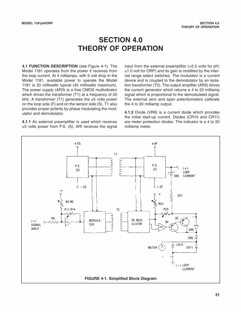
4.1 FUNCTION DESCRIPTION (see Figure 4-1). TheModel 1181 operates from the power it receives fromthe loop current. At 4 milliamps, with 5 volt drop in theModel 1181, available power to operate the Model1181 is 20 milliwatts typical (40 milliwatts maximum).The power supply (AR3) is a free CMOS multivibratorwhich drives the transformer (T1) at a frequency of 20kHz. A transformer (T1) generates the ±5 volts poweron the loop side (F) and on the sensor side (S). T1 alsoprovides proper polarity by phase modulating the mod-ulator and demodulator.
4.1.1 An external preamplifier is used which receives±5 volts power from P.S. (S). ARl receives the signal
input from the external preamplifier (+2.5 volts for pH;±1.0 volt for ORP) and its gain is modified by the inter-nal range select switches. The modulator is a currentdevice and is coupled to the demodulator by an isola-tion transformer (T2). The output amplifier (AR5) drivesthe current generator which returns a 4 to 20 milliampsignal which is proportional to the demodulated signal.The external zero and span potentiometers calibratethe 4 to 20 milliamp output.
4.1.2 Diode (VR6) is a current diode which providesthe initial start-up current. Diodes (CR10 and CR11)are meter protection diodes. The indicator is a 4 to 20milliamp meter.
32
MODEL 1181pH/ORP SECTION 5.0MAINTENANCE AND TROUBLESHOOTING
SECTION 5.0MAINTENANCE AND TROUBLESHOOTING
5.1 GENERAL. This section provides the maintenanceand troubleshooting instructions for the Model 1181 pHand 1181 ORP Two-Wire Transmitters. These unitshave no moving parts and require a minimum of main-tenance. Procedures for standardizing and calibratingthe units are given in Section 3.0, and generally will bethe only “maintenance” required to keep the units ingood operating condition. If the unit is suspected ofhaving a problem, refer to Table 5-1 QuickTroubleshooting. Refer to paragraph 5.2 if trouble can-not be identified and remedied and proceed asinstructed to correct the problem.
5.2 TROUBLESHOOTING. In the event of failure, iso-late the problem to one of the following areas: themeasuring electrodes, the preamplifier located at thesensor assembly, or the Model 1181 Two-WireTransmitter.
5.2.1 Perform the calibration procedure outlined inparagraph 3.2.2 (3.5.3 for ORP) using a mV generator.If the Model 1181 performs properly, the failure is in themeasuring electrodes. Refer to the sensor manual fordetailed troubleshooting of the electrodes.
5.2.2 If the Model 1181 does not calibrate properly asinstructed in paragraph 3.2.2 (3.5.3 for ORP), proceedto the calibration procedure outlined in paragraph 3.2.3(3.5.4 for ORP). This isolates the preamplifier from theModel 1181. If the Model 1181 calibrates as specified,the preamplifier is defective. Refer to the sensor man-ual for ordering information regarding a replacementpreamplifier.
5.2.3 If the Model 1181 does not calibrate as specifiedin paragraph 3.2.3 (3.5.4 for ORP), one or more of theelectronic circuit boards is defective. To minimizedowntime, a complete set of circuit boards should beplaced into service and calibrated.
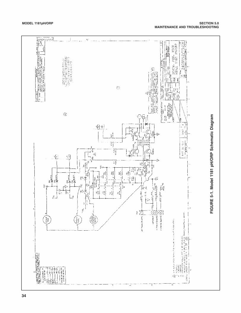
5.2.4 To isolate which of the three circuit boards isdefective, nominal voltages are shown in Figure 5-1.The test points referenced on the schematic diagrammay be located on the individual circuit board locatordiagrams (Figure 6-2, 6-3 and 6-4). For isolating com-ponent failure on an individual board, a block diagramand discussion of each function is included in Section4.0 Theory of Operation.
5.3 MAINTENANCE. The following outlines the proce-dure for disassembly and reassembly of the 1181pH/ORP transmitter.
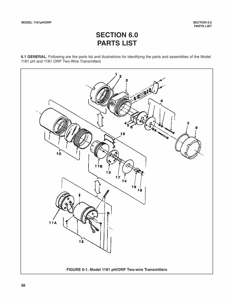
5.3.1 Disassembly Procedure. Remove power priorto disassembly. Follow the steps below to disassemblethe unit (see Figure 6-1 ).
1. Remove cover (1) or meter housing (10). If dam-aged, remove O-rings (2) from housing (3).
2. Remove screw retaining serial label to gainaccess to ZERO and SPAN adjustment screws.
3. Align the external ZERO and SPAN adjustingscrews (3) so the slots are horizontal, pointing endcap to end cap (see Figure 3-1).
4. In circuit side of housing (3) remove circuit boardretaining screws, washers (8) cover (9) and thematrix cover is secured to screws with nylon splitwashers, so remove screws in equal incrementsso the cover is not damaged .
5. Pull straight out on handle (knurled knob) of thecircuit board assemblies.
6. To separate individual boards, remove the retain-ing screw located on the terminal side of the trans-mitter board (6).
7. Remove each board by pulling it straight out fromconnectors.
33
MODEL 1181pH/ORP SECTION 5.0MAINTENANCE AND TROUBLESHOOTING
5.3.2 Reassembly Procedure.
1. Assemble the circuit boards and install the retain-ing screw.
2. Align the ZERO and SPAN adjusting screws (3) onthe housing (3) to the horizontal position, slotspointing end cap to end cap.
3. Align the ZERO and SPAN potentiometers locatedon the power circuit board (5) to the horizontal posi-tion, with blades pointing to circuit boards (4) and(6).
4. Place circuit board assembly into housing (3) bypushing straight in on knurled knob. Make sureboards seat fully into terminals.
5. Install matrix cover (8 or 9), and secure withscrews and washers.
6. Inspect thread connections on housing to makesure five undamaged threads will fully engage forexplosion proof requirements.
7. Inspect the cover O-ring (2) and replace if neces-sary.
8. Install covers on transmitter housing (3).
9. Apply power to unit and perform appropriate cali-bration procedure as instructed in Section 3.0.
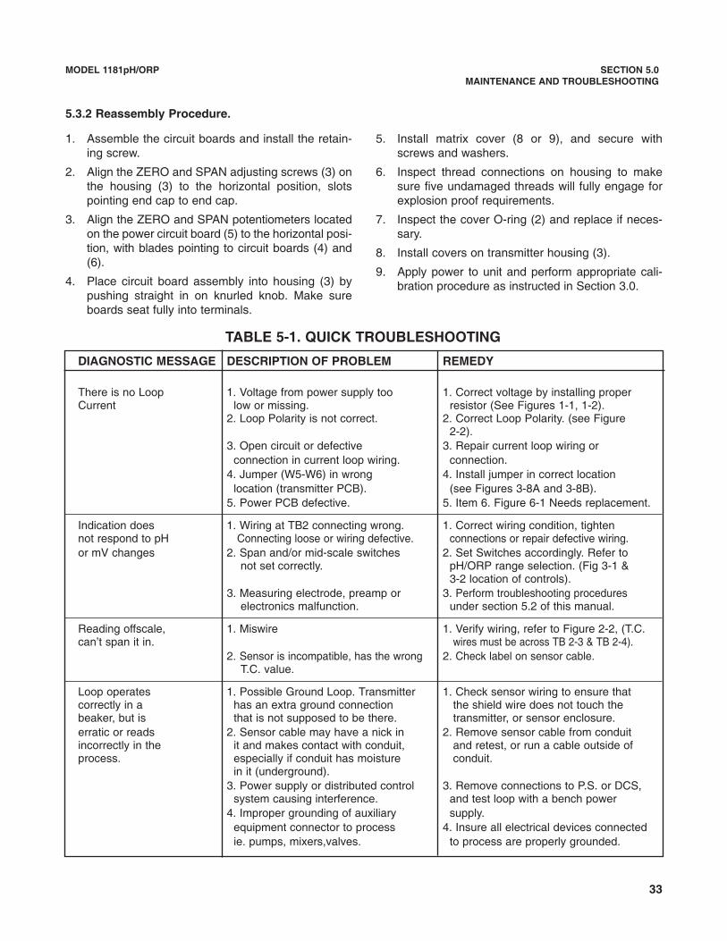
TABLE 5-1. QUICK TROUBLESHOOTING
DIAGNOSTIC MESSAGE DESCRIPTION OF PROBLEM REMEDY
There is no Loop 1. Voltage from power supply too 1. Correct voltage by installing properCurrent low or missing. resistor (See Figures 1-1, 1-2).
2. Loop Polarity is not correct. 2. Correct Loop Polarity. (see Figure 2-2).
3. Open circuit or defective 3. Repair current loop wiring or connection in current loop wiring. connection.
4. Jumper (W5-W6) in wrong 4. Install jumper in correct location location (transmitter PCB). (see Figures 3-8A and 3-8B).
5. Power PCB defective. 5. Item 6. Figure 6-1 Needs replacement.
Indication does 1. Wiring at TB2 connecting wrong. 1. Correct wiring condition, tightennot respond to pH Connecting loose or wiring defective. connections or repair defective wiring.or mV changes 2. Span and/or mid-scale switches 2. Set Switches accordingly. Refer to
not set correctly. pH/ORP range selection. (Fig 3-1 &3-2 location of controls).
3. Measuring electrode, preamp or 3. Perform troubleshooting procedureselectronics malfunction. under section 5.2 of this manual.
Reading offscale, 1. Miswire 1. Verify wiring, refer to Figure 2-2, (T.C.can’t span it in. wires must be across TB 2-3 & TB 2-4).
2. Sensor is incompatible, has the wrong 2. Check label on sensor cable.T.C. value.
Loop operates 1. Possible Ground Loop. Transmitter 1. Check sensor wiring to ensure that correctly in a has an extra ground connection the shield wire does not touch the beaker, but is that is not supposed to be there. transmitter, or sensor enclosure.erratic or reads 2. Sensor cable may have a nick in 2. Remove sensor cable from conduit incorrectly in the it and makes contact with conduit, and retest, or run a cable outside ofprocess. especially if conduit has moisture conduit.
in it (underground).3. Power supply or distributed control 3. Remove connections to P.S. or DCS,
system causing interference. and test loop with a bench power4. Improper grounding of auxiliary supply.
equipment connector to process 4. Insure all electrical devices connectedie. pumps, mixers,valves. to process are properly grounded.
34
MODEL 1181pH/ORP SECTION 5.0MAINTENANCE AND TROUBLESHOOTING
FIG
UR
E 5
-1. M
od
el 1
181
pH
/OR
P S
chem
atic
Dia
gra
m

35
MODEL 1181pH/ORP SECTION 5.0MAINTENANCE AND TROUBLESHOOTING
FIG
UR
E 5
-2. M
od
el 1
181
pH
/OR
P S
chem
atic
Dia
gra
m —
FM
Intr
insi
cally
Saf
e (1
of
3)

MODEL 1181pH/ORP SECTION 5.0MAINTENANCE AND TROUBLESHOOTING
FIG
UR
E 5
-2. M
od
el 1
181
pH
/OR
P S
chem
atic
Dia
gra
m —
FM
Intr
insi
cally
Saf
e (2
of
3)
36
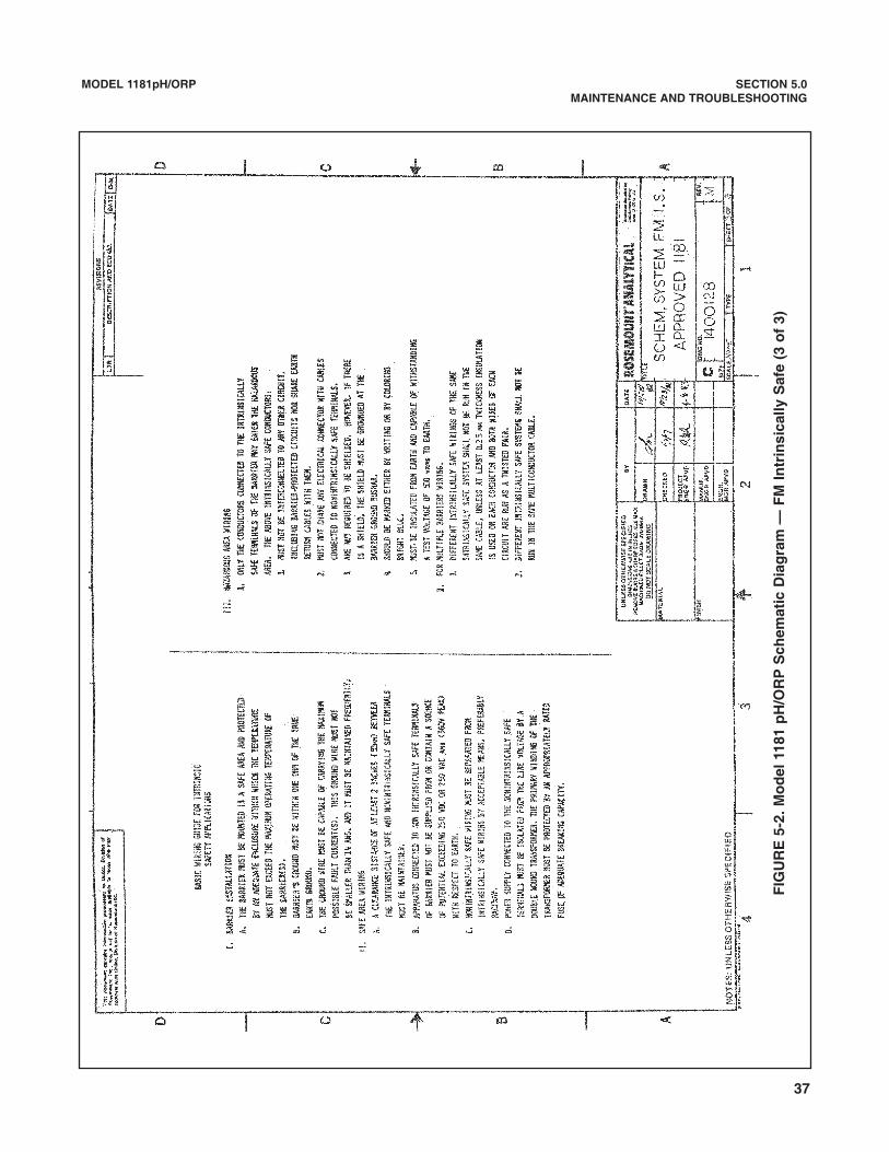
MODEL 1181pH/ORP SECTION 5.0MAINTENANCE AND TROUBLESHOOTING
FIG
UR
E 5
-2. M
od
el 1
181
pH
/OR
P S
chem
atic
Dia
gra
m —
FM
Intr
insi
cally
Saf
e (3
of
3)
37
38
FIGURE 6-1. Model 1181 pH/ORP Two-wire Transmitters
MODEL 1181pH/ORP SECTION 6.0PARTS LIST
SECTION 6.0PARTS LIST
6.1 GENERAL. Following are the parts list and illustrations for identifying the parts and assemblies of the Model1181 pH and 1181 ORP Two-Wire Transmitters
39
MODEL 1181pH/ORP SECTION 6.0PARTS LIST
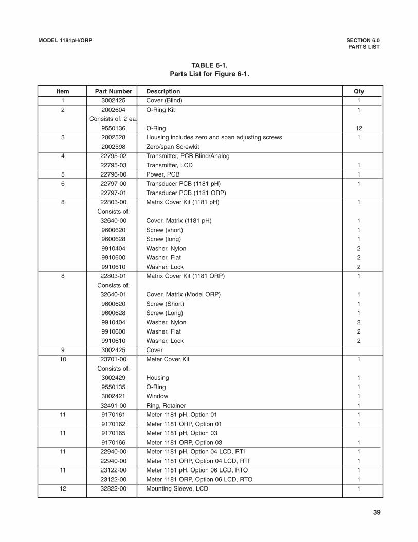
TABLE 6-1.Parts List for Figure 6-1.
Item Part Number Description Qty
1 3002425 Cover (Blind) 1
2 2002604 O-Ring Kit 1
Consists of: 2 ea.
9550136 O-Ring 12
3 2002528 Housing includes zero and span adjusting screws 1
2002598 Zero/span Screwkit
4 22795-02 Transmitter, PCB Blind/Analog
22795-03 Transmitter, LCD 1
5 22796-00 Power, PCB 1
6 22797-00 Transducer PCB (1181 pH) 1
22797-01 Transducer PCB (1181 ORP)
8 22803-00 Matrix Cover Kit (1181 pH) 1
Consists of:
32640-00 Cover, Matrix (1181 pH) 1
9600620 Screw (short) 1
9600628 Screw (long) 1
9910404 Washer, Nylon 2
9910600 Washer, Flat 2
9910610 Washer, Lock 2
8 22803-01 Matrix Cover Kit (1181 ORP) 1
Consists of:
32640-01 Cover, Matrix (Model ORP) 1
9600620 Screw (Short) 1
9600628 Screw (Long) 1
9910404 Washer, Nylon 2
9910600 Washer, Flat 2
9910610 Washer, Lock 2
9 3002425 Cover
10 23701-00 Meter Cover Kit 1
Consists of:
3002429 Housing 1
9550135 O-Ring 1
3002421 Window 1
32491-00 Ring, Retainer 1
11 9170161 Meter 1181 pH, Option 01 1
9170162 Meter 1181 ORP, Option 01 1
11 9170165 Meter 1181 pH, Option 03
9170166 Meter 1181 ORP, Option 03 1
11 22940-00 Meter 1181 pH, Option 04 LCD, RTI 1
22940-00 Meter 1181 ORP, Option 04 LCD, RTI 1
11 23122-00 Meter 1181 pH, Option 06 LCD, RTO 1
23122-00 Meter 1181 ORP, Option 06 LCD, RTO 1
12 32822-00 Mounting Sleeve, LCD 1
40
MODEL 1181pH/ORP SECTION 6.0PARTS LIST
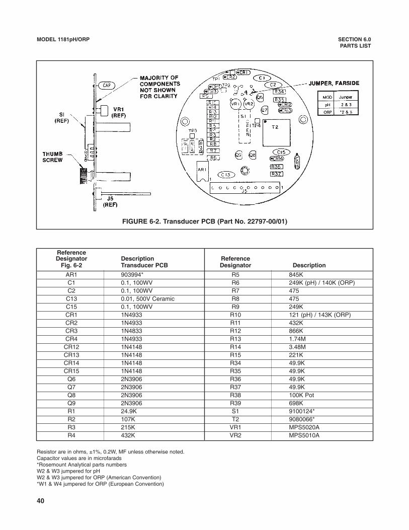
FIGURE 6-2. Transducer PCB (Part No. 22797-00/01)
ReferenceDesignator Description Reference
Fig. 6-2 Transducer PCB Designator Description
AR1 903994* R5 845KC1 0.1, 100WV R6 249K (pH) / 140K (ORP)C2 0.1, 100WV R7 475
C13 0.01, 500V Ceramic R8 475C15 0.1, 100WV R9 249KCR1 1N4933 R10 121 (pH) / 143K (ORP)CR2 1N4933 R11 432KCR3 1N4833 R12 866KCR4 1N4933 R13 1.74M
CR12 1N4148 R14 3.48MCR13 1N4148 R15 221KCR14 1N4148 R34 49.9KCR15 1N4148 R35 49.9K
Q6 2N3906 R36 49.9KQ7 2N3906 R37 49.9KQ8 2N3906 R38 100K PotQ9 2N3906 R39 698KR1 24.9K S1 9100124*R2 107K T2 9080066*R3 215K VR1 MPS5020AR4 432K VR2 MPS5010A
Resistor are in ohms, ±1%, 0.2W, MF unless otherwise noted.Capacitor values are in microfarads*Rosemount Analytical parts numbersW2 & W3 jumpered for pHW2 & W3 jumpered for ORP (American Convention)*W1 & W4 jumpered for ORP (European Convention)
41
MODEL 1181pH/ORP SECTION 6.0PARTS LIST
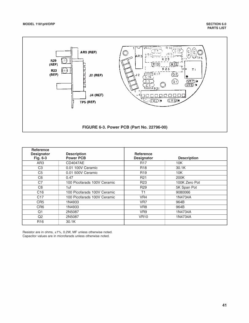
FIGURE 6-3. Power PCB (Part No. 22796-00)
ReferenceDesignator Description Reference
Fig. 6-3 Power PCB Designator DescriptionAR3 CD4047AE R17 10KC3 0.01 100V Ceramic R18 30.1KC5 0.01 500V Ceramic R19 10KC6 0.47 R21 200KC7 100 Picofarads 100V Ceramic R23 100K Zero PotC8 1uf R29 5K Span Pot
C16 100 Picofarads 100V Ceramic T1 9080066C17 100 Picofarads 100V Ceramic VR4 1N4734ACR5 1N4933 VR7 964BCR6 1N4933 VR8 964BQ1 2N5087 VR9 1N4734AQ2 2N5087 VR10 1N4734AR16 30.1K
Resistor are in ohms, ±1%, 0.2W, MF unless otherwise noted.Capacitor values are in microfarads unless otherwise noted.

42
MODEL 1181pH/ORP SECTION 6.0PARTS LIST
FIGURE 6-4. Transmitter PCB (Part No. 22795-00)
ReferenceDesignator Description Reference
Fig. 6-2 Transmitter PCB Designator DescriptionAR5 1CL7611DCPA (9030042*) R25 162KC9 0.01 500V Ceramic R26 13K
C10 0.01 500V Ceramic R27 10KCR9 1N4003 R28 100K
CR10 1N4003 R30 165KCR11 1N4003 R31 49.9 ±1%, 1W
Q4 2N5087 VR3 MPS5010AQ5 92PU51A or 2N6727 VR5 V68MA3BR22 24.9K VR6 J507R24 158K
Resistor are in ohms, ±1%, 0.2W, MF unless otherwise noted.Capacitor values are in microfarads.*Rosemount Analytical parts numbers
43
Model 1181pH/ORP SECTION 7.0RETURN OF MATERIAL
SECTION 7.0RETURN OF MATERIAL
7.1 GENERAL.
To expedite the repair and return of instruments, propercommunication between the customer and the factoryis important. Before returning a product for repair, call1-949-757-8500 for a Return Materials Authorization(RMA) number.
7.2 WARRANTY REPAIR.
The following is the procedure for returning instru-ments still under warranty:
1. Call Rosemount Analytical for authorization.
2. To verify warranty, supply the factory sales ordernumber or the original purchase order number. Inthe case of individual parts or sub-assemblies, theserial number on the unit must be supplied.
3. Carefully package the materials and enclose your“Letter of Transmittal” (see Warranty). If possible,pack the materials in the same manner as theywere received.
4. Send the package prepaid to:
Rosemount Analytical Inc., Uniloc DivisionUniloc Division2400 Barranca ParkwayIrvine, CA 92606
Attn: Factory Repair
RMA No. ____________
Mark the package: Returned for Repair
Model No. ____
7.3 NON-WARRANTY REPAIR.
The following is the procedure for returning for repairinstruments that are no longer under warranty:
1. Call Rosemount Analytical for authorization.
2. Supply the purchase order number, and makesure to provide the name and telephone numberof the individual to be contacted should additionalinformation be needed.
3. Do Steps 3 and 4 of Section 7.2.
NOTEConsult the factory for additional informa-tion regarding service or repair.


WARRANTYSeller warrants that the firmware will execute the programming instructions provided by Seller, and that the Goods manufacturedor Services provided by Seller will be free from defects in materials or workmanship under normal use and care until the expira-tion of the applicable warranty period. Goods are warranted for twelve (12) months from the date of initial installation or eighteen(18) months from the date of shipment by Seller, whichever period expires first. Consumables, such as glass electrodes,membranes, liquid junctions, electrolyte, o-rings, catalytic beads, etc., and Services are warranted for a period of 90days from the date of shipment or provision. Products purchased by Seller from a third party for resale to Buyer ("Resale Products") shall carry only the warranty extended bythe original manufacturer. Buyer agrees that Seller has no liability for Resale Products beyond making a reasonable commercialeffort to arrange for procurement and shipping of the Resale Products. If Buyer discovers any warranty defects and notifies Seller thereof in writing during the applicable warranty period, Seller shall, atits option, promptly correct any errors that are found by Seller in the firmware or Services, or repair or replace F.O.B. point of man-ufacture that portion of the Goods or firmware found by Seller to be defective, or refund the purchase price of the defective por-tion of the Goods/Services. All replacements or repairs necessitated by inadequate maintenance, normal wear and usage, unsuitable power sources, unsuit-able environmental conditions, accident, misuse, improper installation, modification, repair, storage or handling, or any othercause not the fault of Seller are not covered by this limited warranty, and shall be at Buyer's expense. Seller shall not be obligat-ed to pay any costs or charges incurred by Buyer or any other party except as may be agreed upon in writing in advance by anauthorized Seller representative. All costs of dismantling, reinstallation and freight and the time and expenses of Seller's person-nel for site travel and diagnosis under this warranty clause shall be borne by Buyer unless accepted in writing by Seller. Goods repaired and parts replaced during the warranty period shall be in warranty for the remainder of the original warranty peri-od or ninety (90) days, whichever is longer. This limited warranty is the only warranty made by Seller and can be amended onlyin a writing signed by an authorized representative of Seller. Except as otherwise expressly provided in the Agreement, THEREARE NO REPRESENTATIONS OR WARRANTIES OF ANY KIND, EXPRESS OR IMPLIED, AS TO MERCHANTABILITY, FIT-NESS FOR PARTICULAR PURPOSE, OR ANY OTHER MATTER WITH RESPECT TO ANY OF THE GOODS OR SERVICES.
RETURN OF MATERIAL
Material returned for repair, whether in or out of warranty, should be shipped prepaid to:
Emerson Process ManagementLiquid Division
2400 Barranca ParkwayIrvine, CA 92606
The shipping container should be marked:Return for RepairModel _______________________________
The returned material should be accompanied by a letter of transmittal which should include the following information (make acopy of the "Return of Materials Request" found on the last page of the Manual and provide the following thereon):
1. Location type of service, and length of time of service of the device.2. Description of the faulty operation of the device and the circumstances of the failure.3. Name and telephone number of the person to contact if there are questions about the returned material.4. Statement as to whether warranty or non-warranty service is requested.5. Complete shipping instructions for return of the material.
Adherence to these procedures will expedite handling of the returned material and will prevent unnecessary additional chargesfor inspection and testing to determine the problem with the device.
If the material is returned for out-of-warranty repairs, a purchase order for repairs should be enclosed.
Credit Cards for U.S. Purchases Only.
The right people,the right answers,right now.
ON-LINE ORDERING NOW AVAILABLE ON OUR WEB SITEhttp://www.raihome.com
Emerson Process ManagementLiquid Division2400 Barranca ParkwayIrvine, CA 92606 USATel: (949) 757-8500Fax: (949) 474-7250
http://www.raihome.com
© Rosemount Analytical Inc. 2003