planck’s constant in the light of an incandescent lamp olampiad/fizik/jahani... · planck’s...
TRANSCRIPT

36th International Physics Olympiad. Salamanca (España) 2005
Exp. Page 1 of 11
R.S.E.F.
PLANCK’S CONSTANT IN THE LIGHT OF AN INCANDESCENT LAMP
In 1900 Planck introduced the hypothesis that light is emitted by matter in the form of quanta of energy hν. In 1905
Einstein extended this idea proposing that once emitted, the energy quantum remains intact as a quantum of light (that later received the name photon). Ordinary light is composed of an enormous number of photons on each wave front. They remain masked in the wave, just as individual atoms are in bulk matter, but h – the Planck’s constant – reveals their presence. The purpose of this experiment is to measure Planck's constant.
A body not only emits, it can also absorb radiation arriving from outside. Black body is the name given to a body that can absorb all radiation incident upon it, for any wavelength. It is a full radiator. Referring to electromagnetic radiation, black bodies absorb everything, reflect nothing, and emit everything. Real bodies are not completely black; the ratio between the energy emitted by a body and the one that would be emitted by a black body at the same temperature, is called emissivity, ε, usually depending on the wavelength.
Planck found that the power density radiated by a body at absolute temperature T in the form of electromagnetic radiation of wavelength λ can be written as
( )1/5
1
2 −=
Tce
cu
λλ
λε (1)
where c1 and c2 are constants. In this question we ask you to determine c2 experimentally, which is proportional to h.
For emission at small λ, far at left of the maxima in Figure F-1, it is permissible to drop the -1 from the denominator of Eq. (1), that reduces to
/5
1
2 Tce
cu
λλ
λε= (2)
The basic elements of this experimental question are sketched in Fig.
F-2.
• The emitter body is the tungsten filament of an incandescent lamp A that emits a wide range of λ’s, and whose luminosity can be varied.
• The test tube B contains a liquid filter that only transmits a thin band of the visible spectrum around a value λ0 (see Fig. F-3). More information on the filter properties will be found in page 5.
• Finally, the transmitted radiation falls upon a photo resistor C (also known as LDR, the acronym of Light Dependent Resistor). Some properties of the LDR will be described in page 6.
The LDR resistance R depends on its illumination, E, which is
proportional to the filament power energy density
0
0
E uR u
R E
λ γλγ−
−
∝ ⎫⎪ ⇒ ∝⎬∝ ⎪⎭
where the dimensionless parameter γ is a property of the LDR that will be determined in the experiment. For this setup we finally obtain a relation between the LDR resistance R and the filament temperature T TcecR 02 /
3λγ= (3)
that we will use in page 6. In this relation c3 is an unknown proportionality constant. By measuring R as a function on T one can obtain c2, the objective of this experimental question.
F-2
A
B
C
F-3
uλ
λ λ0
F-1
uλ
λ
T3
T2
T1

36th International Physics Olympiad. Salamanca (España) 2005
Exp. Page 2 of 11
R.S.E.F.
DESCRIPTION OF THE APPARATUS
The components of the apparatus are shown in Fig. F-4, which also includes some indications for its setup. Check now that all the components are available, but refrain for making any manipulation on them until reading the instructions in the next page. EQUIPMENT:
1. Platform. It has a disk on the top that holds a support for the LDR, a support for the tube and a support for an electric lamp of 12 V, 0.1 A.
2. Protecting cover. 3. 10 turns and 1 kΩ potentiometer. 4. 12 V battery. 5. Red and black wires with plugs at both ends to connect platform to potentiometer. 6. Red and black wires with plugs at one end and sockets for the battery at the other end. 7. Multimeter to work as ohmmeter. 8. Multimeter to work as voltmeter. 9. Multimeter to work as ammeter. 10. Test tube with liquid filter. 11. Stand for the test tube. 12. Grey filter. 13. Ruler.
An abridged set of instructions for the use of multimeters, along with information on the least squares method, is provided in a separate page.
F-4
1
2
3
6
7 10 11
4
5
8 9 13 12
A V Ω

36th International Physics Olympiad. Salamanca (España) 2005
Exp. Page 3 of 11
R.S.E.F.
SETTING UP THE EQUIPMENT
Follow these instructions:
• Carefully make the electric connections as indicated in Fig. F-4, but do not plug the wires 6 to the potentiometer.
• By looking at Fig. F-5, follow the steps indicated below:
1. Turn the potentiometer knob anticlockwise until reaching the end.
2. Turn slowly the support for the test tube so that one of the lateral holes is in front of the lamp and the other in front of the LDR.
3. Bring the LDR nearer to the test tube support until making a light touch with its lateral hole. It is advisable to orient the LDR surface as indicated in Fig. F-5.
4. Insert the test tube into its support.
5. Put the cover onto the platform to protect from the outside light. Be sure to keep the LDR in total darkness for at least 10 minutes before starting the measurements of its resistance. This is a cautionary step, as the resistance value at darkness is not reached instantaneously.
F-5
2
3
5
1
4

36th International Physics Olympiad. Salamanca (España) 2005
Exp. Page 4 of 11
R.S.E.F.
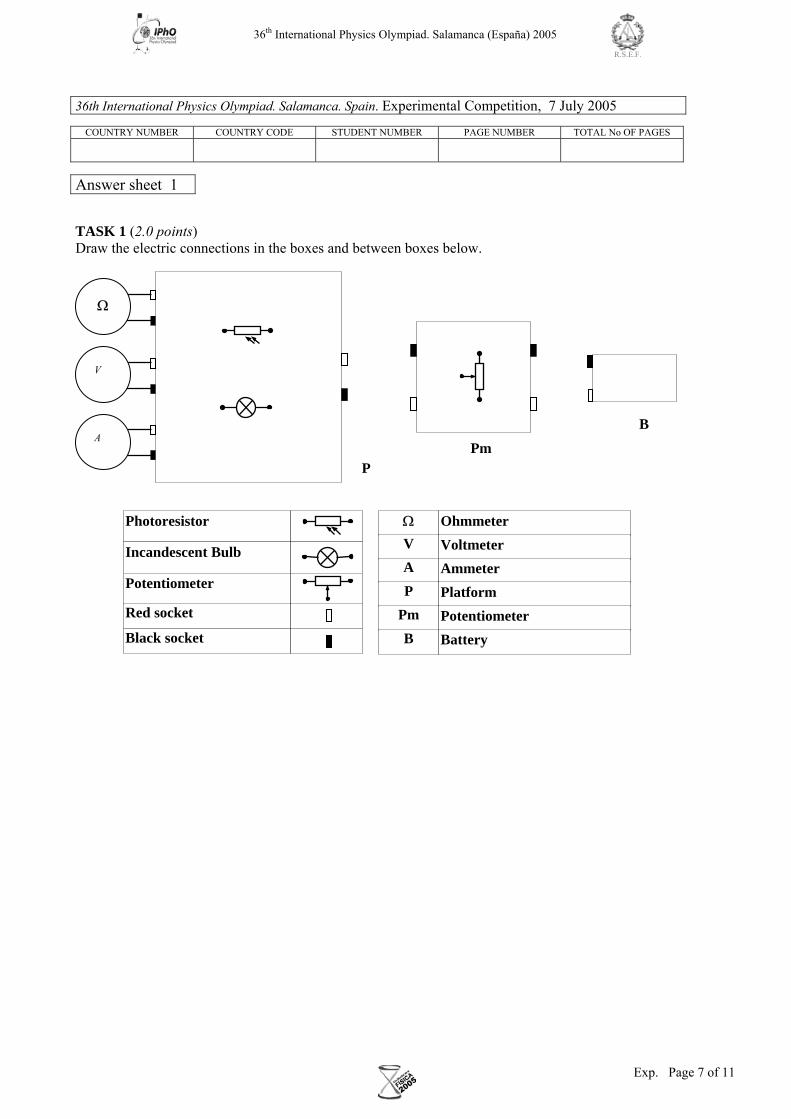
Task 1
Draw in Answer Sheet 1 the complete electric circuits in the boxes and between the boxes, when the circuit is fully connected. Please, take into account the indications contained in Fig. F-4 to make the drawings. Measurement of the filament temperature
The electric resistance RB of a conducting filament can be given as
SlRB ρ= (4)
where ρ is the resistivity of the conductor, l is the length and S the cross section of the filament.
This resistance depends on the temperature due to different causes such as:
• Metal resistivity increases with temperature. For tungsten and for temperatures in the range 300 K to 3655 K, it can be given by the empirical expression, valid in SI units,
83.081005.3 ρ⋅=T (5)
• Thermal dilatation modifies the filament’s length and section. However, its effects on the filament resistance will
be negligible small in this experiment.
From (4) and (5) and neglecting dilatations one gets
83.0BRaT = (6)
• Therefore, to get T it is necessary to determine a. This can be achieved by measuring the filament resistance RB,0 at
ambient temperature T0. Task 2 a) Measure with the multimeter the ambient temperature T0. b) It is not a good idea to use the ohmmeter to measure the filament resistance RB,0 at T0 because it introduces a small
unknown current that increases the filament temperature. Instead, to find RB,0 connect the battery to the potentiometer and make a sufficient number of current readings for voltages from the lowest values attainable up to 1 V. (It will prove useful to make at least 15 readings below 100 mV.) At the end, leave the potentiometer in the initial position and disconnect one of the cables from battery to potentiometer.
Find RB for each pair of values of V and I, translate these values into the Table for Task 2,b) in the Answer Sheets. Indicate there the lowest voltage that you can experimentally attain. Draw a graph and represent RB in the vertical axis against I.
c) After inspecting the graphics obtained at b), select an appropriate range of values to make a linear fit to the data suitable
for extrapolating to the ordinate at the origin, RB,0. Write the selected values in the Table for Task 2, c) in the Answer Sheets. Finally, obtain RB,0 and ∆RB,0.
d) Compute the numerical values of a and ∆a for RB,0 in Ω and T0 in K using (6).

36th International Physics Olympiad. Salamanca (España) 2005
Exp. Page 5 of 11
R.S.E.F.
OPTICAL PROPERTIES OF THE FILTER
The liquid filter in the test tube is an aqueous solution of copper sulphate (II) and Orange (II) aniline dye. The purpose of the salt is to absorb the infrared radiation emitted by the filament.
The filter transmittance (transmitted intensity/incident intensity) is shown in Figure F-6 versus the wavelength.
0
5
10
15
20
25
30
450 500 550 600 650 700 750λ /nm
% transmittance
F-6 Task 3
Determine λ 0 and ∆λ from Fig. F-6. Note: 2 ∆λ is the total width at half height and λ 0 the wavelength at the maximum.
36th International Physics Olympiad. Salamanca (España) 2005
Exp. Page 6 of 11
R.S.E.F.
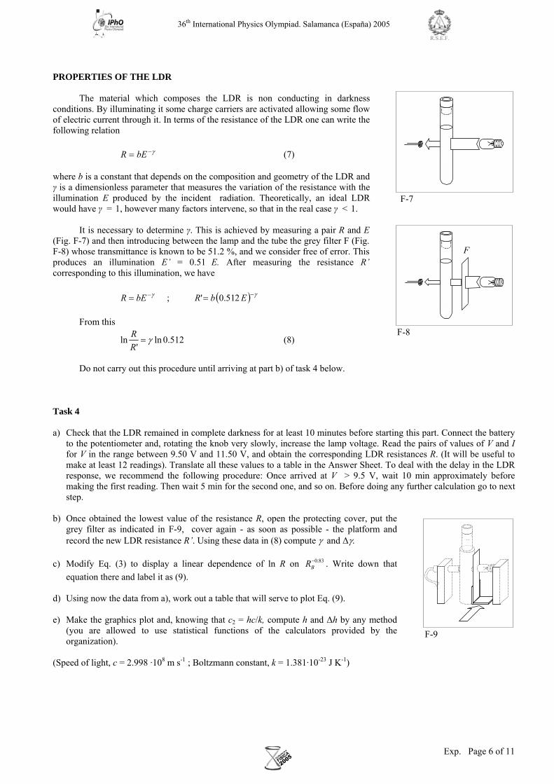
PROPERTIES OF THE LDR
The material which composes the LDR is non conducting in darkness conditions. By illuminating it some charge carriers are activated allowing some flow of electric current through it. In terms of the resistance of the LDR one can write the following relation γ−= bER (7) where b is a constant that depends on the composition and geometry of the LDR and γ is a dimensionless parameter that measures the variation of the resistance with the illumination E produced by the incident radiation. Theoretically, an ideal LDR would have γ = 1, however many factors intervene, so that in the real case γ < 1.
It is necessary to determine γ. This is achieved by measuring a pair R and E (Fig. F-7) and then introducing between the lamp and the tube the grey filter F (Fig. F-8) whose transmittance is known to be 51.2 %, and we consider free of error. This produces an illumination E’ = 0.51 E. After measuring the resistance R’ corresponding to this illumination, we have
( ) γγ −− == EbRbER 251.0' ;
From this
512.0ln'
ln γ=RR (8)
Do not carry out this procedure until arriving at part b) of task 4 below.
Task 4 a) Check that the LDR remained in complete darkness for at least 10 minutes before starting this part. Connect the battery
to the potentiometer and, rotating the knob very slowly, increase the lamp voltage. Read the pairs of values of V and I for V in the range between 9.50 V and 11.50 V, and obtain the corresponding LDR resistances R. (It will be useful to make at least 12 readings). Translate all these values to a table in the Answer Sheet. To deal with the delay in the LDR response, we recommend the following procedure: Once arrived at V > 9.5 V, wait 10 min approximately before making the first reading. Then wait 5 min for the second one, and so on. Before doing any further calculation go to next step.
b) Once obtained the lowest value of the resistance R, open the protecting cover, put the
grey filter as indicated in F-9, cover again - as soon as possible - the platform and record the new LDR resistance R’. Using these data in (8) compute γ and ∆γ.
c) Modify Eq. (3) to display a linear dependence of ln R on 0.83
BR− . Write down that equation there and label it as (9).
d) Using now the data from a), work out a table that will serve to plot Eq. (9). e) Make the graphics plot and, knowing that c2 = hc/k, compute h and ∆h by any method
(you are allowed to use statistical functions of the calculators provided by the organization).
(Speed of light, c = 2.998 ·108 m s-1 ; Boltzmann constant, k = 1.381·10-23 J K-1)
F
F-8
F-9
F-7
36th International Physics Olympiad. Salamanca (España) 2005
Exp. Page 7 of 11
R.S.E.F.
36th International Physics Olympiad. Salamanca. Spain. Experimental Competition, 7 July 2005
COUNTRY NUMBER COUNTRY CODE STUDENT NUMBER PAGE NUMBER TOTAL No OF PAGES
Answer sheet 1
TASK 1 (2.0 points) Draw the electric connections in the boxes and between boxes below.
Pm
B
Ω
V
A
P
Photoresistor
Incandescent Bulb
Potentiometer
Red socket
Black socket
Ohmmeter Ω
Voltmeter V
Ammeter A
Platform P
Potentiometer Pm
Battery B

36th International Physics Olympiad. Salamanca (España) 2005
Exp. Page 8 of 11
R.S.E.F.
36th International Physics Olympiad. Salamanca. Spain. Experimental Competition, 7 July 2005
COUNTRY NUMBER COUNTRY CODE STUDENT NUMBER PAGE NUMBER TOTAL No OF PAGES
Answer sheet 2
TASK 2 a) (1.0 points) T0 =
b) (2.0 points)
V I RB
Vmin = * * This is a characteristic of your apparatus. You can´t go below it.

36th International Physics Olympiad. Salamanca (España) 2005
Exp. Page 9 of 11
R.S.E.F.
36th International Physics Olympiad. Salamanca. Spain. Experimental Competition, 7 July 2005
COUNTRY NUMBER COUNTRY CODE STUDENT NUMBER PAGE NUMBER TOTAL No OF PAGES
Answer sheet 3
TASK 2 c) (2.5 points)
V I RB
RB0 = ∆ RB0 =
d) (1.0 points)
a = ∆a =
TASK 3 (1.0 points)
λ0 = ∆λ =

36th International Physics Olympiad. Salamanca (España) 2005
Exp. Page 10 of 11
R.S.E.F.
36th International Physics Olympiad. Salamanca. Spain. Experimental Competition, 7 July 2005
COUNTRY NUMBER COUNTRY CODE STUDENT NUMBER PAGE NUMBER TOTAL No OF PAGES
Answer sheet 4
TASK 4 a) (2.0 points)
V I R
b) (1.5 points)
R =
γ =
R’ =
∆γ =
c) (1.0 points)
Eq. (9)

36th International Physics Olympiad. Salamanca (España) 2005
Exp. Page 11 of 11
R.S.E.F.
36th International Physics Olympiad. Salamanca. Spain. Experimental Competition, 7 July 2005
COUNTRY NUMBER COUNTRY CODE STUDENT NUMBER PAGE NUMBER TOTAL No OF PAGES
Answer sheet 5
TASK 4 d) (3.0 points) V I R
e) (3.0 points)
h =
∆ h =

36th International Physics Olympiad. Salamanca (España) 2005
Th 1 Page 1 of 3
R.S.E.F.
v∆
0v
0r
F-1
m
Th 1 AN ILL FATED SATELLITE
The most frequent orbital manoeuvres performed by spacecraft consist of velocity variations along the direction of flight, namely accelerations to reach higher orbits or brakings done to initiate re-entering in the atmosphere. In this problem we will study the orbital variations when the engine thrust is applied in a radial direction.
To obtain numerical values use: Earth radius m10376 6⋅= .RT , Earth surface gravity 2m/s819.g = , and take the length of the sidereal day to be h0240 .T = .
We consider a geosynchronous1 communications satellite of mass m placed in an equatorial circular orbit of radius 0r . These satellites have an “apogee engine” which provides the tangential thrusts needed to reach the final orbit.
Marks are indicated at the beginning of each subquestion, in parenthesis.
Question 1
1.1 (0.3) Compute the numerical value of 0r .
1.2 (0.3+0.1) Give the analytical expression of the velocity 0v of the satellite as a function of g, TR , and 0r , and calculate its numerical value.
1.3 (0.4+0.4) Obtain the expressions of its angular momentum 0L and mechanical energy 0E , as functions of 0v , m, g and TR .
Once this geosynchronous circular orbit has been reached (see Figure F-1), the satellite has been stabilised in the desired location, and is being readied to do its work, an error by the ground controllers causes the apogee engine to be fired again. The thrust happens to be directed towards the Earth and, despite the quick reaction of the ground crew to shut the engine off, an unwanted velocity variation v∆ is imparted on the satellite. We characterize this boost by the parameter 0v/v∆β = . The duration of the engine burn is always negligible with respect to any other orbital times, so that it can be considered as instantaneous.
Question 2
Suppose 1<β .
2.1 (0.4+0.5) Determine the parameters of the new orbit2, semi-latus-rectum l and eccentricity ε , in terms of 0r and β.
2.2 (1.0) Calculate the angle α between the major axis of the new orbit and the position vector at the accidental misfire.
2.3 (1.0+0.2) Give the analytical expressions of the perigee minr and apogee maxr distances to the Earth centre, as functions of 0r and β , and calculate their numerical values for 4/1=β .
2.4 (0.5+0.2) Determine the period of the new orbit, T, as a function of 0T and β, and calculate its numerical value for 4/1=β .
1 Its revolution period is 0T . 2 See the “hint”.
Image: ESA

36th International Physics Olympiad. Salamanca (España) 2005
Th 1 Page 2 of 3
R.S.E.F.
Question 3
3.1 (0.5) Calculate the minimum boost parameter, escβ , needed for the satellite to escape Earth gravity.
3.2 (1.0) Determine in this case the closest approach of the satellite to the Earth centre in the new trajectory, minr ′ , as a function of 0r .
Question 4
Suppose escββ > .
4.1 (1.0) Determine the residual velocity at the infinity, ∞v , as a function of 0v and β.
4.2 (1.0) Obtain the “impact parameter” b of the asymptotic escape direction in terms of 0r and β. (See Figure F-2).
4.3 (1.0+0.2) Determine the angle φ of the asymptotic escape direction in terms of
β. Calculate its numerical value for escββ23
= .
HINT
Under the action of central forces obeying the inverse-square law, bodies follow
trajectories described by ellipses, parabolas or hyperbolas. In the approximation m << M
the gravitating mass M is at one of the focuses. Taking the origin at this focus, the general
polar equation of these curves can be written as (see Figure F-3)
( )θε
θcosl
r−
=1
where l is a positive constant named the semi-latus-rectum and ε is the eccentricity of the
curve. In terms of constants of motion:
2
2
mMG
Ll = and
2/1
322
221 ⎟
⎟
⎠
⎞
⎜⎜
⎝
⎛+=
mMG
LEε
where G is the Newton constant, L is the modulus of the angular momentum of the orbiting mass, with respect to the origin, and E is its
mechanical energy, with zero potential energy at infinity.
We may have the following cases:
i) If 10 <≤ ε , the curve is an ellipse (circumference for 0=ε ).
ii) If 1=ε , the curve is a parabola.
iii) If 1>ε , the curve is a hyperbola.
m
M
θ
r
F-3
φ
v∆
0v
∞vb
0r
F-2

36th International Physics Olympiad. Salamanca (España) 2005
Th 1 Page 3 of 3
R.S.E.F.
COUNTRY CODE STUDENT CODE PAGE NUMBER TOTAL No OF PAGES
Th 1 ANSWER SHEET
Question Basic formulas and ideas used
Analytical results Numerical results Marking guideline
1.1 =0r 0.3
1.2 =0v =0v 0.4
1.3 =0L
=0E
0.4
0.4
2.1
=l
=ε
0.4
0.5
2.2 =α 1.0
2.3
=
=
min
max
r
r
=
=
min
max
r
r 1.2
2.4 =T =T 0.7
3.1 =escβ 0.5
3.2 =′minr 1.0
4.1 =∞v 1.0
4.2 =b 1.0
4.3 =φ =φ 1.2

36th International Physics Olympiad. Salamanca (España) 2005
Th 2 Page 1 of 3
R.S.E.F.
Th 2 ABSOLUTE MEASUREMENTS OF ELECTRICAL QUANTITIES
The technological and scientific transformations underwent during the XIX century produced a compelling need of
universally accepted standards for the electrical quantities. It was thought the new absolute units should only rely on the standards of length, mass and time established after the French Revolution. An intensive experimental work to settle the values of these units was developed from 1861 until 1912. We propose here three case studies.
Marks are indicated at the beginning of each subquestion, in parenthesis. Determination of the ohm (Kelvin)
A closed circular coil of N turns, radius a and total resistance R is rotated with uniform angular velocity ω about a vertical diameter in a horizontal magnetic
field iBBrr
00 = .
1. (0.5+1.0) Compute the electromotive force ε induced in the coil, and also the
mean power1 P required for maintaining the coil in motion. Neglect the coil
self inductance.
A small magnetic needle is placed at the center of the coil, as shown in Figure F-1. It is free to turn slowly around the Z axis in a horizontal plane, but it cannot follow the rapid rotation of the coil.
2. (2.0) Once the stationary regime is reached, the needle will set at a direction making a small angle θ with 0Br
.
Compute the resistance R of the coil in terms of this angle and the other parameters of the system.
Lord Kelvin used this method in the 1860s to set the absolute standard for the ohm. To avoid the rotating coil, Lorenz devised an alternative method used by Lord Rayleigh and Ms. Sidgwick, that we analyze in the next paragraphs.
Determination of the ohm (Rayleigh, Sidgwick).
The experimental setup is shown in Figure F-2. It consists of two identical metal disks D and D' of radius b mounted on the conducting shaft SS'. A motor rotates the set at an angular velocity ω , which can be adjusted for measuring R. Two identical coils C and C' (of radius a and with N turns each) surround the disks. They are connected in such a form that the current I flows through them in opposite directions. The whole apparatus serves to measure the resistance R.
1 The mean value X of a quantity ( )tX in a periodic system of period T is ( )∫=
TdttX
TX
0
1
You may need one or more of these integrals:
02
0
2
0
2
0cossincossin === ∫∫∫
πππdxxxdxxdxx , π
ππ== ∫∫
2
02
2
02 cossin dxxdxx , and later 11
1nn
nx dx x +
+=∫
G
D
4
C
C' S'
S
F-2
D'
1
2
ω R
I
3
X
Z
F-1
0Br
θ
ω

36th International Physics Olympiad. Salamanca (España) 2005
Th 2 Page 2 of 3
R.S.E.F.
3. (2.0) Assume that the current I flowing through the coils C and C' creates a uniform magnetic field B around D and D', equal to the one at the centre of the coil. Compute1 the electromotive force ε induced between the rims 1 and 4, assuming that the distance between the coils is much larger than the radius of the coils and that a >> b.
The disks are connected to the circuit by brush contacts at their rims 1 and 4. The galvanometer G detects the flow of current through the circuit 1-2-3-4.
4. (0.5) The resistance R is measured when G reads zero. Give R in terms of the physical parameters of the system.
Determination of the ampere
Passing a current through two conductors and measuring the force between them provides an absolute determination of the current itself. The “Current Balance” designed by Lord Kelvin in 1882 exploits this method. It consists of six identical single turn coils C1… C6 of radius a, connected in series. As shown in Figure F-3, the fixed coils C1, C3, C4, and C6 are on two horizontal planes separated by a small distance 2h. The coils C2 and C5 are carried on balance arms of length d, and they are, in equilibrium, equidistant from both planes.
The current I flows through the various coils in such a direction that the magnetic force on C2 is upwards while that on C5 is downwards. A mass m at a distance x from the fulcrum O is required to restore the balance to the equilibrium position described above when the current flows through the circuit.
5. (1.0) Compute the force F on C2 due to the magnetic interaction with C1. For simplicity assume that the force per unit length is the one corresponding to two long, straight wires carrying parallel currents.
6. (1.0) The current I is measured when the balance is in equilibrium. Give the value of I in terms of the physical parameters of the system. The dimensions of the apparatus are such that we can neglect the mutual effects of the coils on the left and on the right.
Let M be the mass of the balance (except for m and the hanging parts), G its centre of mass and l the distance .OG
7. (2.0) The balance equilibrium is stable against deviations producing small changes zδ in the height of C2 and zδ− in C5. Compute2 the maximum value maxzδ so that the balance still returns towards the equilibrium
position when it is released.
2 Consider that the coils centres remain approximately aligned.
Use the approximations 211
1ββ
β+≈
±m or 2
21
1
1β
βm≈
± for 1<<β , and θθ tansin ≈ for small θ.
x m
d
C1
C2
C3
h
h F
FF
F
d
O
G
C6
C5
C4
l
F-3
I

36th International Physics Olympiad. Salamanca (España) 2005
Th 2 Page 3 of 3
R.S.E.F.
COUNTRY CODE STUDENT CODE PAGE NUMBER TOTAL No OF PAGES
Th 2 ANSWER SHEET
Question Basic formulas used Analytical results Marking guideline
1
ε =
=P
1.5
2
R =
2.0
3
ε =
2.0
4
R =
0,5
5
F =
1.0
6
I =
1.0
7
=maxzδ
2.0

36th International Physics Olympiad. Salamanca (España) 2005
Th 3 Page 1 of 3
R.S.E.F.
Th 3 NEUTRONS IN A GRAVITATIONAL FIELD
In the familiar classical world, an elastic bouncing ball on the Earth’s surface is an ideal example for perpetual
motion. The ball is trapped: it can not go below the surface or above its turning point. It will remain bounded in this state, turning down and bouncing up once and again, forever. Only air drag or inelastic bounces could stop the process and will be ignored in the following.
A group of physicists from the Institute Laue - Langevin in Grenoble reported1 in 2002 experimental evidence on the behaviour of neutrons in the gravitational field of the Earth. In the experiment, neutrons moving to the right were allowed to fall towards a horizontal crystal surface acting as a neutron mirror, where they bounced back elastically up to the initial height once and again.
The setup of the experiment is sketched in Figure F-1. It consists of the opening W, the neutron mirror M (at height z = 0), the neutron absorber A (at height z = H and with length L) and the neutron detector D. The beam of neutrons flies with constant horizontal velocity component vx from W to D through the cavity between A and M. All the neutrons that reach the surface of A are absorbed and disappear from the experiment. Those that reach the surface of M are reflected elastically. The detector D counts the transmission rate N(H), that is, the total number of neutrons that reach D per unit time.
Marks are indicated at the beginning of each subquestion, in parenthesis.
The neutrons enter the cavity with a wide range of positive and negative vertical velocities, vz. Once in the cavity, they fly between the mirror below and the absorber above.
1. (1.5) Compute classically the range of vertical velocities vz(z) of the neutrons that, entering at a height z, can arrive at the detector D. Assume that L is much larger than any other length in the problem.
2. (1.5) Calculate classically the minimum length Lc of the cavity to ensure that all neutrons outside the previous velocity range, regardless of the values of z, are absorbed by A. Use vx = 10 m s-1 and H = 50 µm.
The neutron transmission rate N(H) is measured at D. We expect that it increases monotonically with H.
3. (2.5) Compute the classical rate Nc(H) assuming that neutrons arrive at the cavity with vertical velocity vz and at height z, being all the values of vz and z equally probable. Give the answer in terms of ρ, the constant number of neutrons per unit time, per unit vertical velocity, per unit height, that enter the cavity with vertical velocity vz and at height z.
1 V. V. Nesvizhevsky et al. “Quantum states of neutrons in the Earth’s gravitational field.” Nature, 415 (2002) 297. Phys Rev D 67,
102002 (2003).
g D
M
A
W
X
Z vx vz
z H
L A
M
D
F-1

36th International Physics Olympiad. Salamanca (España) 2005
Th 3 Page 2 of 3
R.S.E.F.
The experimental results obtained by the Grenoble group
disagree with the above classical predictions, showing instead that the value of N(H) experiences sharp increases when H crosses some critical heights H1, H2 … (Figure F-2 shows a sketch). In other words, the experiment showed that the vertical motion of neutrons bouncing on the mirror is quantized. In the language that Bohr and Sommerfeld used to obtain the energy levels of the hydrogen atom, this can be written as: “The action S of these neutrons along the vertical direction is an integer multiple of the Planck action constant h”. Here S is given by
∫ === ...3,2,1,)( nhndzzpS z (Bohr-Sommerfeld quantization rule)
where pz is the vertical component of the classical momentum, and the integral covers a whole bouncing cycle. Only neutrons with these values of S are allowed in the cavity.
4. (2.5) Compute the turning heights Hn and energy levels En (associated to the vertical motion) using the Bohr-Sommerfeld quantization condition. Give the numerical result for H1 in µm and for E1 in eV.
The uniform initial distribution ρ of neutrons at the entrance changes, during the flight through a long cavity, into the step-like distribution detected at D (see Figure F-2). From now on, we consider for simplicity the case of a long cavity with H < H2. Classically, all neutrons with energies in the range considered in question 1 were allowed through it, while quantum mechanically only neutrons in the energy level E1 are permitted. According to the time-energy Heisenberg uncertainty principle, this reshuffling requires a minimum time of flight. The uncertainty of the vertical motion energy will be significant if the cavity length is small. This phenomenon will give rise to the widening of the energy levels.
5. (2.0) Estimate the minimum time of flight tq and the minimum length Lq of the cavity needed to observe the first sharp increase in the number of neutrons at D. Use vx = 10 m s-1.
Data:
Planck action constant s J 10 6.63 -34⋅=h Speed of light in vacuum -18 s m 10 3.00 ⋅=c Elementary charge C 10 1.60 -19⋅=e Neutron mass kg 10 1.67 -27⋅=M Acceleration of gravity on Earth g = 9.81 m s-2
If necessary, use the expression: ( ) ( )3
1212/32/1 xdxx −
−=−∫
HH1
N(H)
F-2
H2

36th International Physics Olympiad. Salamanca (España) 2005
Th 3 Page 3 of 3
R.S.E.F.
COUNTRY CODE STUDENT CODE PAGE NUMBER TOTAL No OF PAGES
Th 3 ANSWER SHEET
Question Basic formulas used Analytical results Numerical results Marking guideline
1 ≤≤ )(zvz 1.5
2 Lc = Lc = 1.5
3 Nc(H)= 2.5
4
Hn =
En =
H1= µm
E1 = eV
2.5
5
tq =
Lq =
tq =
Lq =
2.0