paragraphs with this symbol contain important information
TRANSCRIPT

1 GSM Scout active LTE Rev. 01 Paragraphs with this symbol contain important information concerning the device and its handling. In any case, you should take these into account in order to prevent questions and mis-understandings. Paragraphs with the ssf character indicate special functions that are activated when the device is switched to ssf mode (see Chapter 10 for more on this).

2GSM Scout active LTE Rev. 01 Introduction / manufacturer’s declaration Dear customer, Thank you for purchasing this registration system. The GSM Scout activ LTE was built according to the latest technology. It is a microcontroller-controlled signaling module for remote data transmission in GSM radio telephone networks. manufacturer: ConiuGo® GmbH Berliner Strasse 4a 16540 Hohen Neuendorf For the CE marking are important and have been noted: - Directive 2014/53 / EU (Radio Equipment Directive - RED) on radio equipment - Directive 2011/65 / EU (RoHS-conformity), (in particular lead free of all processed components) The device includes a telecommunications terminal used for GSM, UMTS and LTE networks. This has its own CE mark with check digit. When using a separate power supply, it should be noted that this corresponds to the conditions of electrical safety, carries the CE mark and is professionally mounted and operated. Hohen Neuendorf, 10 of September 2018 To ensure the safe operation of our GSM device, you as a user must comply with this operating manual.

3 GSM Scout active LTE Rev. 01 Contents Introduction / manufacturer’s declaration ................................................. 2 Contents ........................................................................................................ 3 1. Warranty and liability conditions ............................................................ 4 2. Intended use .............................................................................................. 5 3. Safety constructions ................................................................................ 6 4. Assembly ................................................................................................... 8 5. Switch inputs and function of the GSM Scout ..................................... 9 6. Configuration via the phone number directory ................................... 13 7. Insert SIM card and connect antenna ................................................... 15 8. Start of the device and functional test ................................................. 15 9. Remote switching ................................................................................... 16 10. Ssf – Special SIM function ................................................................... 19 11. Switching the language version .......................................................... 22 12. Remedy for errors and problems ........................................................ 23 13. Scope of delivery and optional accessories ...................................... 26

4GSM Scout active LTE Rev. 01 1. Warranty and liability conditions ConiuGo® GmbH guarantees that the product is free of material and manufacturing defects during normal use and maintenance. This warranty is valid for 2 years from the date of delivery and covers repair or replacement, whereby ConiuGo® GmbH reserves the right to choose. The warranty covers material and personnel costs in the event of a repair, but not on assembly and shipping costs. A guarantee is excluded in case of improper use, alteration, disassembly or modifica-tion. The proof of purchase must be enclosed with a return! In no event shall ConiuGo® be liable for any incidental or consequential damages, including property damage, loss of use of the equipment or other equipment, or any loss of property. Damage caused by non-observance of these operating instruc-tions will void the warranty! For further damages we do not accept liability! In case of property damage or personal injury caused by im-proper handling or non-observance of the safety instructions, we assume no liability. In such cases, any warranty claim ex-pires.

5 GSM Scout active LTE Rev. 01 2. Intended use The device is made for use in Germany. It may be marketed outside of Germany, Austria and Switzerland only with a user manual in the local language. This manual must be authorized by the manufacturer. In any case, it must be ensured that the end user of this device is able to understand the manual in terms of language and content. Note on installing ConiuGo® devices in vehicles
• In order to avoid disturbances of the vehicle electronics, a ConiuGo® device in vehicles must always be installed by a technically trained electrician and, if necessary, registered in the vehicle computer. As a rule, this is possible with-out any problems. • If ConiuGo® units are installed in vehicles, they may only be operated in the resting vehicle (for example, theft protection). The devices have no E1 ap-proval. Repercussions on vehicle electronics can therefore not be completely ruled out. Note about possible malfunction of the vehicle electronics • State-of-the-art vehicles have an electronic battery management system that indicates a fault and, if necessary, immobilizes the vehicle when an "unknown consumer" is detected. Such an "unknown consumer" may be a GSM modem or GSM reporting device that is not registered with its power management in battery management. The operator or the person authorized by him must en-sure that the vehicle electronics properly recognize the ConiuGo® device and allow it to be used in the vehicle. • The ConiuGo® Society for Telecommunications is not liable for disruptions of the vehicle electronics or the consequential costs, such as the costs for re-leasing a vehicle on-board computer, which has switched to the fault mode. The operator or his workshop have to ensure that the device works properly with the vehicle electronics!

6GSM Scout active LTE Rev. 01 Installation and commissioning of the GSM reporting device require special expertise (telecommunications, electrical engi-neering, electronics, etc.). Proper installation and commission-ing must be ensured by the purchaser or operator. The safety instructions must be observed. Observance of all instructions in this manual and the technical documentation and instructions on the device (type plate, etc.) are required. In case of doubt, the device should be put out of operation and the manufacturer consulted.
• The device usually has protection class IP 31. This must be taken into acount when selecting the installation environment. • The permissible ambient temperature is -30 to 60 ° C. • The device may only be operated indoors. • Contact with moisture (> 70% rel. F) must be avoided at all costs. • An activated SIM card is required for operation. Another use as described above leads to damage of this product. Moreover, this is with dangers such. As short circuit, fire, electric shock, etc. connected. Devices of the GSM Scout series must not be technically modified or rebuilt! 3. Safety hints The devices of the GSM Scout series comply with the generally valid GSM stand-ards. The following safety instructions must be observed. GSM devices can ignite explosive or flammable gas mixtures electromagnetically. The use of the devices under impermissible environmental conditions must be excluded. Deviating device versions, such as GSM Scout devices with protection class IP 65 have the corresponding protection class and can of course be operated under the conditions specified for this protection class.
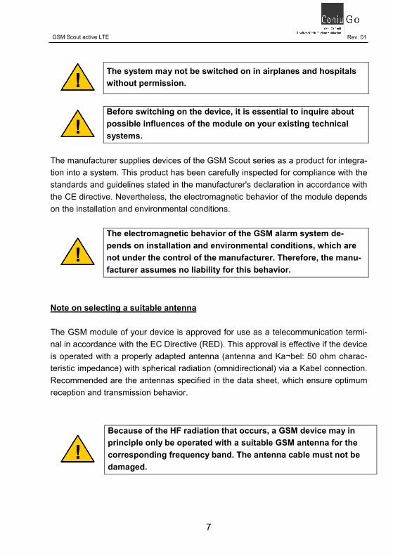
7 GSM Scout active LTE Rev. 01 The system may not be switched on in airplanes and hospitals without permission. Before switching on the device, it is essential to inquire about possible influences of the module on your existing technical systems. The manufacturer supplies devices of the GSM Scout series as a product for integra-tion into a system. This product has been carefully inspected for compliance with the standards and guidelines stated in the manufacturer's declaration in accordance with the CE directive. Nevertheless, the electromagnetic behavior of the module depends on the installation and environmental conditions. The electromagnetic behavior of the GSM alarm system de-pends on installation and environmental conditions, which are not under the control of the manufacturer. Therefore, the manu-facturer assumes no liability for this behavior. Note on selecting a suitable antenna The GSM module of your device is approved for use as a telecommunication termi-nal in accordance with the EC Directive (RED). This approval is effective if the device is operated with a properly adapted antenna (antenna and Ka¬bel: 50 ohm charac-teristic impedance) with spherical radiation (omnidirectional) via a Kabel connection. Recommended are the antennas specified in the data sheet, which ensure optimum reception and transmission behavior. Because of the HF radiation that occurs, a GSM device may in principle only be operated with a suitable GSM antenna for the corresponding frequency band. The antenna cable must not be damaged.

8GSM Scout active LTE Rev. 01 4. Assembly The devices of the GSM Scout series with IP 31 housing have two mounting straps ("B" in Fig. 1) on the housing, which are used for wall mounting. Note that the two other screw holes ("A" in Fig. 1) are used to secure the housing cover. (see Fig. 1) Fig. 1
B B A A

9 GSM Scout active LTE Rev. 01 5. Switch inputs and function of the GSM Scout The devices of the GSM Scout series are GSM transmitter modules for the transmis-sion of messages via alarm SMS. They serve to secure and monitor valuable objects such as houses, boats / yachts, camping vehicles, etc.). Messages are sent via SMS (SMS = Short Message Service) via the GSM networks (GSM = Global System for Mobile communications). The GSM Scout active LTE is also able to receive SMS and thereby perform remote switching tasks. Fig. 2 The GSM Scout Series has 5 inputs for switches or switch contacts (see Fig. 2 / A = AUX, B = FIRE, C = WATER, D = BURGLARY, E = SHARP). Voltages should never be created here! Only the connection of potential-free contacts or signaling loops is permitted! The input contacts are only suitable for potential-free contacts. Under no circumstances should they be subjected to a voltage. With the input "SCHARF" (E) the functions of the device are activated. After closing this switch, arming will be activated after 40 seconds have elapsed. This delay time is used to leave the protected object after arming. The associated light emitting diode (hereinafter abbreviated as LED = Light Emitting Diode) above the contact only shows the status of the input (open / closed) and not whether the device is actually armed. The actual condition can be seen by the status LED 1 on the left side.
1 2 3 A B C D E

10GSM Scout active LTE Rev. 01 Arming via SMS: It is also possible to arm or disarm the device via SMS. This is done via an SMS with the content "Scharf" or "Unscharf" (without quotes), which must be sent to the device. Uppercase and lowercase letters are mandatory! Since modern smartphones often automatically add a space after a word, the SMS keywords will also be recognized in this case. For the device state, the process that took place last in time is definitive in every case. Both the corresponding SMS and a change of state at the arm-ing switch (from sharp to unsharp or vice versa) are carried out by the de-vice. Instead of „Scharf“, „Alarm+“ or „Switchon“ can be used. Instead of „Unscharf“, „Alarm-“ or „Switchoff“ can be used. The input contacts:
• The entrance "Einbruch" is intended for a signaling loop with door or window contacts. Again, an LED indicates whether the reporting loop is closed or interrupted. If this input is not used, it is recommended to bridge the two contacts with a piece of wire. The burglary input is the only one designed so that a closed signaling loop (LED on) represents the idle state. If the message loop is interrupted, an SMS message is issued (SMS only if al-ready armed). In the case of a hardware-related arming (wire bridge), the actual arming is delayed by 30 seconds after the power supply has been applied in order to be able to leave the object without alarm. In order to make it possible to enter the object when the GSM alarm system is switched on in order to switch the system out of focus, the alarm SMS "burglary" is sent with a delay of 30 seconds.

11GSM Scout active LTE Rev. 01 When using ssf functions, please note that the "Burglary" input can have a different function (for more information, see Chapter 10 "Ssf functions").
• The input "Wasser" is intended for the switching contact of a water level switch. The LED via the input indicates the switching status. An SMS mes-sage is absetzgesetzt when the switch contact is closed (SMS only if sharp geschal¬tet). • The input "Feuer" is intended for the switching contact of a fire or smoke de-tector. The LED via the input indicates the switching status. An SMS mes-sage is sent when the switch contact is closed (SMS only if armed). • The input "Aux" is intended for a further, arbitrary switching contact. The LED via the input indicates the switching status. An SMS message is is-sued when the switch contact is closed (SMS only, if it is turned off sharp-ly). The operating status is indicated by three further LEDs: • LED 1 (Fig. 2) indicates whether the device is armed or disarmed. The ar-ming is initiated via the corresponding switching contact and takes place with a delay of 40 seconds. If the device is armed with a corresponding SMS ("armed"), the conversion takes place immediately and without delay after receipt of the SMS. • The LED 2 (Fig. 2) indicates whether the device was able to establish contact with a GSM provider. • The LED 3 (Fig. 2) indicates whether the GSM alarm system could success-fully read out the information stored on the SIM card. Further display functions of LEDs 1 to 3: • After switching on, all three LEDs light up for a short time at the same time. This is a functional test that indicates that the device is operating properly.

12GSM Scout active LTE Rev. 01 Please note that when using the ssf functions, the LEDs will flash to indicate the activated ssf functions (see Chapter 10 "ssf Functions" for details). The device recognizes the activation of the ssf functions on a corresponding entry on the SIM card. Connecting an additional LED as an external status display (armed / out of focus) If the arming of the GSM Scout is to be displayed outside the device, another green LED (cable length up to 5 m) can be connected to the connector provided (see "LED" in Fig. 3). The preresistor for a green LED is already on the board. Fig. 3 Disabling the LED (darken): If you want to deactivate the LED (for example, to save electricity or to avoid abnor-malities in a dark room), you remove the jumper ("jumper" in Fig. 3). Inserting the jumper activates the LED function again. Please also note the following notes on the function of the device: Depending on the GSM provider, there may be delays in the transmission of SMS. As a rule, however, SMS are delivered within a few seconds. LED jumper

13GSM Scout active LTE Rev. 01 Operation of the system in the GSM network causes telephone costs. Incorrect entry of telephone numbers may result in high charges. ConiuGo® GmbH rejects any responsibility and advis-es to thoroughly test the parameterized module. 6. Configuration via the phone number directory The numbers to which the GSM Scout sends its SMS, this refers to the directory of the SIM card. Please proceed as follows when setting these numbers and functions:
• Switch off the PIN request of the SIM card via the menus in the mobile phone. As a rule, this function can be found in the Security menu item in your mobile phone (SIM cards that do not permit PIN deactivation are un-suitable). • Change to the menu item "Phone book" of your mobile phone. Select the phonebook to be stored on the SIM card. You can check whether you have described the phonebook stored on the SIM by inserting the SIM card into another cell phone. There, the settings must also be seen in the directory number. • Now enter four names and telephone numbers in the directory as shown in the example below. Each entry stands for a specific event: SIM-card Associated event name: telephone number SMS 1 +49301234567 burglary SMS 2 water SMS 3 017123456789 fire SMS 4 017876543210 aux The telephone numbers are freely selectable. If you do not want to use an event, please do not enter a phone number. In the example shown, the Sms2 (event water) would not be supported. However, the entry as a name must be present in the phonebook, since the device searches for all four entries at startup!

14GSM Scout active LTE Rev. 01 Please note that if you enter wrong phone numbers, the function will be impaired as the module can not send messages to the correct destination. All four entries must be present in the telephone memory of the SIM card. It is case-sensitive. Please note that when using Ssf functions, the following entry must be included in the SIM card phonebook: ssf0000000000 (See Chapter 10 "Ssf Functions" for more explanation).

15GSM Scout active LTE Rev. 01 7. Insert SIM card and connect antenna Fig. 4 With the insertion of the SIM card, the con-nection of the antenna and the power supply, the device is ready for operation: Open the device and insert the SIM card into the SIM card holder ("SIM "Fig.4).
• Screw the housing carefully. • Connect the antenna to the right side of the housing ("ANT" Fig.4). The an- antenna must have a SMA connector. 8. Start of the device and functional test Connect the power supply ("DC" in Fig.4) to the fully prepared device: Permitted is the supply voltage indicated on the rating plate of your scout (9 - 35 Volt). The polarity of the plug-in contact (5.5 x 2.1 mm, 14 mm long) is as follows:
• The correct supply voltage specified on the rating plate must be adhered to! • For other supply voltages (12 Volt DC battery, mains supply 230 Volt AC, etc.) suitable accessories are available from the manufacturer. • Also available from the manufacturer are battery packs with charging cables for different types of power supply.
ANT SIM DC

16GSM Scout active LTE Rev. 01 After applying the supply voltage, the device carries out its self-test (LED 1, LED 2 and LED 3 - see Fig. 2 - light up for a short time). To monitor the function of the device, observe LED 2 and LED 3. If the device is armed (LED 1 lights up / flashes), these indicate that the device has established contact with the GSM network (LED 2) and successfully read out the SIM card infor-mation (LED 3). Now you should test the device, whereby you first check the function of all reporting lines. Use a shorting bridge (wire section, tweezers or similar) to con-nect the two contacts of the inputs Aux ("A" Fig.2) Fire ("B" Fig.2) and Water ("C" Fig.2) and trigger the respective alarm message. With the inverted input burglary ("D" Fig.2) a message is triggered when it is open! 9. Remote switching In addition to the alarm and signaling functions, the GSM Scout active LTE has the possibility to perform remote switching functions via two relays installed in the de-vice. The connection terminals for the relays can be found on the left side of the board, as shown in the picture (Fig. 5). Fig. 5 The digital outputs are relay outputs that have a changeover contact. The connection designations of the relays are: Rel. 1 Rel.2 C NC NO C NC NO

17GSM Scout active LTE Rev. 01 C „common“ = center contact NC „normally closed“ = closed in normal condition NO „normally open“ = open in normal condition
� The relays of the devices react to the following SMS messages that are to be sent to the SIM card number in the device (spaces must be observed without fail! Messages with texts that do not exactly match the specifications are ignored by the device): � SMS with the text Rel.1 + or Rel.2 + The relevant relay is permanently switched on. � SMS with the text Rel.1 - or Rel.2 - The relevant relay is switched off per-manently. � SMS with the text Rel.1 nnn or Rel.2 nnn The relevant relay is switched on for nnn seconds. The value of nnn may be between 001 and 600 for switch-ing times of 1 bto 600 seconds (do not forget the zeroes that are standing ahead). nnn stands for the following values: • 000 - the relevant relay is switched off permanently (as with -) • 999 - the relevant relay is permanently switched on (as with +) • 001 ... 600 the relevant relay is switched on for 1 ... 600 seconds Since modern smartphones often automatically add a space after a word, the SMS key texts are also recognized in this case. It can never be ruled out that the GSM network fails or the de-vice is temporarily unavailable. By means of the remote switch-ing function, you should never permanently activate a device in the object from which hazards can arise! The remote switching function with time limit offers greater security here, because after the time has elapsed a shutdown occurs.

18GSM Scout active LTE Rev. 01 In addition to sending an SMS in the case of an event (fire, water, burglary, aux), the two integrated relays can also be switched directly from the controller for a prede-termined period of time, without the detour via the GSM network an actuator (eg a siren or a pump) (general alarm). To set up a general alarm (without incoming SMS), the following entries are re-quired in the SIM card phonebook: Memory SIM card: name telefone number Relais1 nnn Relais2 nnn nnn stands for the following values: • 000 - the relevant relay is switched off permanently • 999 - the relevant relay is permanently switched on • 001 ... 600 the relevant relay is switched on for 1 ... 600 seconds Example: The following entry is in the phone book Relais1 – 250 In the event of an event relay 1 is switched on for 250 seconds.
The switching contacts of the relays in the device must never be connected to mains voltage 230 Volt AC. The maximum contact load is 24 Volts / 1 A switching capability. With the event-dependent switching of the relays (general alarm), the relays can not be linked to any specific event! They are triggered at every event (fire, water, aux, burglary)!

19GSM Scout active LTE Rev. 01 10. Ssf – Special SIM functions Ssf is a special mode that allows the user to activate more functions in the GSM Scout active LTE. The ssf functions are for the experienced user who wants to solve special tasks with the GSM Scout. There is no compelling need to use the SsF functions. In any case, it is recommended to first use, learn and apply the device in its standard functions. The functions are activated via a key to be stored on the SIM card. name number Ssf0000000000 „any“ Please note: To be able to use the ssf function, the key must be present in the phonebook of the SIM card! for example: Ssf1000000100 The key defines ten different special functions over ten different positions that can be assigned "0" or "1". In the form shown above, all functions are disabled by the "0". The functions can be activated by setting the "0" assigned to the function to "1" in the key. The ten positions represent the following functions: Ssf 0 0 0 0 0 0 0 0 0 0 a b c d e f g h i j a.) Transmission of the transmission quality with each SMS b.) Transferring the account balance with prepaid card with each SMS c.) Switch on inversion at input 1 (burglary) d.) acknowledgment of all incoming SMS on the device e.) PIN to be given by the user for incoming SMS

20GSM Scout active LTE Rev. 01 f.) Freely configurable message texts g.) Reserved for later functions h.) Reserved for later functions i.) Reserved for later functions j.) SMS message to all registered numbers at an event a.) Transmission of quality of service (Ssf key 1) If this key is set to 1, the GSM scout determines the quality of the connection to the GSM network before sending an SMS and attaches the information in the form of "SQ: value" to the SMS text. The following values apply: 1 – 4: almost no reception 5 – 8: bad reception 9 – 24: moderate to good reception 25 – 31: very good reception b.) Transfer of the account balance for "prepaid SIM cards" (SSF key 2) If this key is set to 1, the GSM Scout asks before submitting an SMS the status of the prepaid account and appends the information to the end of the SMS text. To ensure the function, an entry with the service number of the fee transfer must be added to the SIM card. As a name, Geb is to be entered for "fees". The service num-ber of the provider is entered as the telephone number. If no service number is en-tered, the fee transfer does not work. In any case, an entry named Geb must be stored on the SIM card when this function is activated, otherwise the device will not perform the function. If no charges could be obtained, "No Charges Info!" Or "No charge info!" Will be sent. Some providers send additional information, including changing information, in addition to the fees. Therefore, it can not always be guaranteed that the correct information can be delivered.

21GSM Scout active LTE Rev. 01 Examples of service numbers (for Germany): O2: *101# Vodafone: *102# T-Mobil: *100# c.) Inverted input 1 (Ssf - key 3) If this key is set to 1, the first input "Burglary" works as an inverted input with a delay of 30 seconds. This means that the contact loop must be opened to signal an event. If the key is set to 0, the input works like the other inputs too: to trigger the message event, the contact must be closed. d.) Acknowledgment of all incoming SMS (Ssf key 4) If this key is set to 1, the device sends each incoming SMS (if the device recognizes it as a message), as an SMS back to the phone number from which the message was sent. This applies to all SMS with usable content (including those for the relays), but not for any other SMS (for example, information from the provider, SMS advertis-ing, etc.). e.) PIN for incoming SMS (Ssf key 5) If this key is set to 1, the device searches for a PIN entry on the SIM card that con-tains a 4-digit PIN number. For this, another entry must be made on the SIM card: example: name telephone number Pin0385 any The name contains the recognition word pin and the fixed password of 4 characters. If this ssf function is activated, only incoming SMS will be processed by the device, preceded by this PIN in the text. From Rel.1 005 then has to be e.g. 0385Rel.1 005 to get started. f.) Configurable message texts (Ssf key 6) If this key is set to 1, the message texts can be almost freely configured. Configura-ble texts are appended to the SMS ID in the name of the phonebook entry. If no text is stored, the standard text Alarm1 to Alarm4 is used. The text can be up to 12 char-acters long.

22GSM Scout active LTE Rev. 01 Example: name send SMS annotation Sms1 alarm1 standard text Sms2disorder disorder individual text Sms3heater heater individual text Sms4123456789012345 123456789012 number, over 12 characters Please note that with configurable texts only a maximum of 12 characters are taken over, as can be seen in example SMS 4. g.) to i.) Reserved for possible later functions (Ssf keys 7 to 9) This key is reserved for later functions and must be set to "0". j.) Parallel call to all registered numbers at event (Ssf key 10) If this key is set to 1, occurring events are transmitted to all registered numbers that are entered for the individual inputs on the SIM card. 11. Switching the language version The GSM Scout active LTE has SMS messages in German, English, French and Spanish. If required, the languages can be switched via an additional entry on the SIM card. If no entry exists, the language German is selected. lenguage entry SIM number English Lang-Eng „any“ French Lang-Fra „any“ Spain Lang-Spa „any“
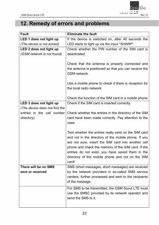
23GSM Scout active LTE Rev. 01 12. Remedy of errors and problems Fault Eliminate the fault LED 1 does not light up (The device is not armed) If the device is switched on, after 40 seconds the LED starts to light up via the input "SHARP". LED 2 does not light up (GSM network is not found) Check whether the PIN number of the SIM card is deactivated. Check that the antenna is properly connected and the antenna is positioned so that you can receive the GSM network. Use a mobile phone to check if there is reception for the local radio network. Check the function of the SIM card in a mobile phone LED 3 does not light up (The device does not find the entries in the call number directory) Check if the SIM card is inserted correctly. Check whether the entries in the directory of the SIM card have been made correctly. Pay attention to the case. Test whether the entries really exist on the SIM card and not in the directory of the mobile phone. If you are not sure, insert the SIM card into another cell phone and check the memory of the SIM card. If the entries do not exist, you have saved them in the directory of the mobile phone and not on the SIM card! There will be no SMS sent or received SMS (short messages, short messages) are received by the network providers in so-called SMS service centers, further processed and sent to the recipients of the message. For SMS to be transmitted, the GSM Scout LTE must use the SMSC provided by its network operator and send the SMS to it.

24GSM Scout active LTE Rev. 01 The SMSC number is stored on the SIM card in many cases. The GSM device can then read these out. If there are any problems with the sending or receipt of SMS messages, the SMSC used should be checked. If necessary, the SMSC number must be stored on the SIM card or in the GSM device (to be stored). Error with incorrect or unknown SMSC number: • No SMS will be sent. • No SMS is received. • By detours via non-optimal SMSC from other providers SMS are delivered very late • (up to several days late). • By way of non-optimal SMSC from other pro-viders, the delivery of SMS is very irregular (sometimes immediately, sometimes with de-lay, sometimes not at all). • By detours over non-optimal SMSC from other providers, SMS will be charged at increased costs (roaming, tariffing is not taken into ac-count). For the reasons mentioned, it is strongly advised to use the SMSC provided by the provider. The number of the SMSC can be found in the net-work service whose SIM card is used. Some important SMSC. The information is without guarantee:

25GSM Scout active LTE Rev. 01 (Excerpt from the ConiuGo document Meaning of the SMS SMS service center, which can be downloaded from the ConiuGo website)
T-Mobile (direct costumer) +49 171 076 0000 Vodafone (only internally) +49 172 227 0000 o2 Loop (Prepaid) +49 176 000 0433 1und1 +49 172 227 0333 ALDI-TALK +49 177 061 0000 blau.de +49 177 061 0000 BILDmobil +49 172 227 0333 Congstar +49 171 076 0000 Klarmobil (T-mob. 0171) +49 171 076 0000 klarmobil (O2 0176) +49 176 000 0443 simyo +49 177 061 0000 TchiboMobil +49 176 000 0443 Debitel +49 171 076 0333 Victorvox +49 171 076 0322 Manual entry of the number of an SMSC A sure sign of the lack of information about the SMSC is when you can not send SMS but only receive it. In a mobile phone or smartphone, you can control or change the information about the SMSC on the SIM. You may have to manually set the SMS Service Center number (SMSC). In an older mobile phone you will find the setting under the menu item SIM configuration (or similar). Here's an example of an Android ™ smartphone 4.0, 4.4 or later On the home screen, select the application screen icon. Touch phone. Enter * # * # 4636 # * # *.

26GSM Scout active LTE Rev. 01 Select phone information. Scroll to SMSC. Select Refresh to get the current number. If an error (update error or update error) is displayed, enter the correct SMSC number in the input field in the correct format and tap on Update. Here is an example of an Android ™ smartphone 4.1, 4.2 or 4.3 On the home screen, select the application screen icon. Touch “messages”. Select the menu button (three vertical dots) and go to Settings. Change the number of the SMS service center in the SIM settings; to do this, select the SMS center number and enter the SMSC number in the input field. 13. Scope of delivery and optional accessories The scope of delivery of the GSM Scout series includes:
• Device • Housing screws • Operation manual • Cable with DC circular connector • Miniature srewdriver • Deviations from the scope of delivery are subject to products in cases in which special agreements have been made with spe-cialist dealers or distributors. The following accessories are available for the GSM Scout series: Plug-in power supply 230V AC / 12V DC (305307214) Disc mount antenna, 1,5m, SMA- connection (300300304S) Circular antenna PUK (SMA für outdoor use (300303310S) Other accessories on request.

27GSM Scout active LTE Rev. 01

28GSM Scout active LTE Rev. 01