hios blg bc2 programming instructions - asg jergensproducts.asg-jergens.com/asset/asg hios blg-bc2...
TRANSCRIPT

ASG, Division of Jergens, Inc.
15700 S. Waterloo Road | Cleveland, OH 44110-3898 Phone: (888) 486-6163 | Fax: (216) 481-4519
Email: [email protected] | Web: www.asg-jergens.com Page 1 of 12© 2016 Jergens, Inc. All Rights Reserved | Revision Date: 6/9/2016
HIOS BLG BC2 Programming Instructions User Manual

ASG, Division of Jergens, Inc.
15700 S. Waterloo Road | Cleveland, OH 44110-3898 | Phone: (888) 486-6163 | Fax: (216) 481-4519 | Email: [email protected] | www.asg-jergens.com
Page 2 of 12
Table of Contents
User Interface Display and Button Functions ........................................................... 3
Screw Count and Value Setting Display Section .............................................. 3
Function Display Section ................................................................................. 3
F1 Button ........................................................................................................ 4
F2 and F3 Buttons ........................................................................................... 4
Pass LED .......................................................................................................... 4
Fail LED ........................................................................................................... 4
Quick Start Procedure .............................................................................................. 5
Navigating the User Interface .................................................................................. 7
Setting the Functions ............................................................................................... 8
Enable or Disable Error Proofing ..................................................................... 8
Fastener Count ................................................................................................ 8
Setting the Minimum Revolutions ................................................................... 8
Setting the Maximum Revolutions .................................................................. 8
Setting the Work Reset Timer .......................................................................... 9
Setting the Reverse Count Timer ..................................................................... 9
Setting the Buzzer ........................................................................................... 9
Setting the Min/Max Alarm Buzzer ................................................................. 9
Viewing the Cycle Totals ............................................................................... 10
Adjust the Re-Hit Time .................................................................................. 10
Additional Common Functions ............................................................................... 10
Reset the Count ............................................................................................ 10
Exiting the User Interface (Saving Changes) ................................................. 10
Verify Firmware Version ................................................................................. 11
General Information ............................................................................................... 11
Fastener Count .............................................................................................. 11
Counter On/Off.............................................................................................. 11
Minimum/Maximum Revolutions .................................................................. 11
Work Reset Timer and Reverse Count Timer .................................................. 12
Re-Hit Timer .................................................................................................. 12
Optional Equipment ............................................................................................... 12
ESD RoHS Properties .............................................................................................. 12
HIOS BLG BC2 Programming InstructionsUser Manual

ASG, Division of Jergens, Inc.
15700 S. Waterloo Road | Cleveland, OH 44110-3898 | Phone: (888) 486-6163 | Fax: (216) 481-4519 | Email: [email protected] | www.asg-jergens.com
Page 3 of 12
BC2 Programming Instructions
User Interface Display and Button Functions
HIOS BLG BC2 Programming InstructionsUser Manual
BLG-4000 BC2 and BLG-5000 Series BC2 tools feature a built in Screw Counter and a Pulse System. The Pulse System is a mechanism using an electronic signal (Pulse) that occurs during motor revolutions. By installing several fasteners into the assembly the driver learns the number of motor revolutions required to correctly tighten the fasteners to the desired torque. The driver then establishes a minimum and maximum number of revolutions for an acceptable fastener and displays the results using the RED and GREEN LEDs on the display.
The visual display and audible signals combine to alert the operator to the screw count status and will prevent missed or improperly driven fasteners. BC2 tools also feature an optional I/O capability which when combined with a PLC can provide full process control.
The BC2 interface will show numbers, letters or symbols, depending what mode the system is in. It also contains red “FAIL” LED, a green “PASS” LED and 3 programing buttons, F1, F2 & F3 complete the BC2 tool interface.
Screw Count and Value Setting Display Section
Function Display Section
• The batch count is set and the screw count is displayed when the counter function is ON. After starting the assembly the number of fasteners remaining is displayed. The count decreases with each fastener properly installed.
• The numbers for setting the various functions appear here when that function is being set.
• The symbols corresponding to the functions are displayed while in Set Up Mode (See Pages 7 and 8)
ASG, Division of Jergens, Inc.
15700 S. Waterloo Road | Cleveland, OH 44110-3898 | Phone: (888) 486-6163 | Fax: (216) 481-4519 | Email: [email protected] | www.asg-jergens.com
Page 4 of 12
User Interface Display and Button Functions (Continued)
HIOS BLG BC2 Programming InstructionsUser Manual
F1 Button
F2 and F3 Buttons
Pass LED***
Fail LED***
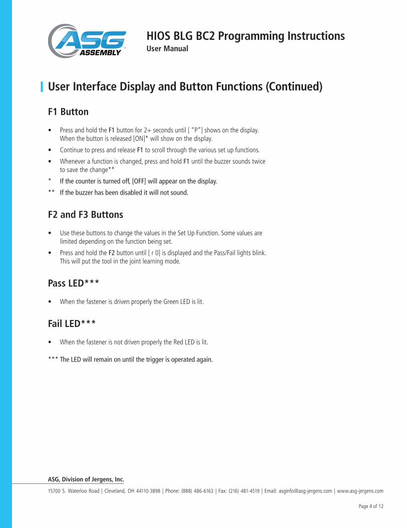
• Press and hold the F1 button for 2+ seconds until [ “P”] shows on the display. When the button is released [ON]* will show on the display.
• Continue to press and release F1 to scroll through the various set up functions.
• Whenever a function is changed, press and hold F1 until the buzzer sounds twice to save the change**
* If the counter is turned off, [OFF] will appear on the display.
** If the buzzer has been disabled it will not sound.
• Use these buttons to change the values in the Set Up Function. Some values are limited depending on the function being set.
• Press and hold the F2 button until [ r 0] is displayed and the Pass/Fail lights blink. This will put the tool in the joint learning mode.
• When the fastener is driven properly the Green LED is lit.
• When the fastener is not driven properly the Red LED is lit.
*** The LED will remain on until the trigger is operated again.

ASG, Division of Jergens, Inc.
15700 S. Waterloo Road | Cleveland, OH 44110-3898 | Phone: (888) 486-6163 | Fax: (216) 481-4519 | Email: [email protected] | www.asg-jergens.com
Page 5 of 12
Quick Start Procedure
HIOS BLG BC2 Programming Instructions User Manual
Important! Before actually learning the joint, drive 1 or 2 fasteners to “exercise” the tool and set up the starting position of the clutch.
1. Press and hold the F2 button until [r 0] is seen on the display and both the Pass & Fail LEDS blink.
2. Start learning the joint by driving 3 or more of the same fastener into the same joint. Make sure to use the same fasteners, parts and method of pick up to be used in production. As you drive each fastener you will see the actual number of motor revolutions displayed.
3. Press the F3 button to select an acceptable range for the Pass/Fail criteria. This will be displayed in the following order; ±0%,±5%,±10%,±15%,±20%.
4. Press the F1 button to confirm the reference values for Pass/Fail and the acceptable range. The display will alternate between showing the Maximum and Minimum numbers of motor revolutions for the joint learned. Pressing F3 while these numbers are flashing allows you to change the ±% for Pass/Fail and will display the new numbers for the Maximum and Minimum values as changed by the selected %
Example: Say the reference values for an acceptable fastener are Min 90 and Max 120 and the range selected is 0%. Any fastener driven where the motor turns between 91 and 119 revolutions, and the clutch shuts off, will result in a Pass, or Green LED. Fewer than 90 or more than 120 revolutions will result in a Fail, or Red LED. If the motor is run for 90 revolutions or more and the trigger is released, with no clutch shut off (ABORT), the result is a Fail or Red LED.

ASG, Division of Jergens, Inc.
15700 S. Waterloo Road | Cleveland, OH 44110-3898 | Phone: (888) 486-6163 | Fax: (216) 481-4519 | Email: [email protected] | www.asg-jergens.com
Page 6 of 12
Quick Start Procedure (Continued)
HIOS BLG BC2 Programming Instructions User Manual
5. Press and hold the F2 button until the buzzer sounds twice, the Minimum and Maximum values and the word HIOS scroll across the display to complete learning the joint.
6. Press and hold the F1 button for 2+ seconds to see [P ] on the display, then release to see [ON ] show on the display. Press the F1 button once to see [n05 ] with the “5” flashing. This would indicate that the count is set to 5 fasteners.
7. To change the count, press the F3 button. Each press of the button will increase the flashing number by one count, up to 9, after 9 the count will start over at 0.
The count, or batch, can be set between 1 and 99, press the F2 button to move from the ones place to the tens place, press the F3 button again to increase the tens place between 0 and 9.
When finished setting the count, save and exit by pressing and holding the F1 button until you hear the buzzer* sound twice and the word HIOS scrolls across the display.* If the buzzer has been disabled it will not sound!
The Quick Start Procedure may set a wider range between the Minimum number of rotations and the Maximum number of rotations than you would want. By using the set up mode functions you can customize the set up to where you could detect a missing washer or an improper length fastener.

ASG, Division of Jergens, Inc.
15700 S. Waterloo Road | Cleveland, OH 44110-3898 | Phone: (888) 486-6163 | Fax: (216) 481-4519 | Email: [email protected] | www.asg-jergens.com
Page 7 of 12
Navigating the User Interface
HIOS BLG BC2 Programming Instructions User Manual
The following shows the different displays as seen in the order they appear as you scroll through the different functions by pressing and releasing the F1 button. The numbers shown in the display drawings below are the factory default settings and will change to reflect the values you choose for your application
Instructions on how to set each different function can be found starting on page 8
1. Press and hold F1 for 2+ seconds until [P ] appears to enter the setup mode. Release the F1 button to see [On ] show on the display.
2. With [On ] showing, press and release F1 to see [n05] on the display. With [n05] showing, press and release F1 to see [u60 ] on the display.
3. With [u60] showing, press and release F1 to see [n20] on the display. With [n20] showing, press and release F1 to see [├ 1.0] on the display
4. With [├ 1.0] showing, press and release F1 to see [ r 0.4] on the display. With [ r 0.4] showing, press and release F1 to see [ d03] on the display.
5. With [ d03] showing, press and release F1 to see [U 3] on the display. With [U 3] showing, press and release F1 to see [L00] on the display.

ASG, Division of Jergens, Inc.
15700 S. Waterloo Road | Cleveland, OH 44110-3898 | Phone: (888) 486-6163 | Fax: (216) 481-4519 | Email: [email protected] | www.asg-jergens.com
Page 8 of 12
Navigating the User Interface (Continued)
Setting the Functions
HIOS BLG BC2 Programming InstructionsUser Manual
6. With [L00] showing, press and release F1 to see [≡0.5] on the display. Continue to press and release F1 to return to the beginning, or press and hold F1 for 2+ seconds to exit the User Interface
• NOTE: The numbers shown in the above illustrations and mentioned in the text below are the factory default settings. These numbers will change to reflect the values you select for your application.
1. Enable or Disable Error Proofing: (see screens 1&2 on page 7) To enable or disable error proofing, press and hold F1 for 2+ seconds. [P ] will show on the display until the button is released. When the button is released, either the word [On ] or [OFF] will show on the display. Press and release F3 to toggle between [On ] and [OFF]. Press and hold F1 for 2+ seconds to save and exit. When [OFF] is selected the tool will operate like a regular driver.
2. Fastener Count: (see screen #3 on page 7) The fastener count shows on the display when the driver is in use. Each time a fastener is driven properly the number on the display will decrease by 1. When the last fastener is driven 0 will show on the display for a period of time before the count is reset. To change the count get to screen #3 [n05] with the 5 flashing on the display, by following the instructions for navigating on page 6. To change the count, press and release F3 to increase the ones digit between 0 and 9. Press F2 to select the tens digit and press F1 to increase between 1 and 9. Press and hold F1 for more than 2 seconds to save and exit.
3. Setting the Minimum Revolutions: (see screen #4 on page 7) Note: the BC2 counts the motor revolutions, not the actual revolutions of the fastener! Get to screen #4 with [u60] showing with the 0 flashing on the display by following the instructions for navigating on page 7. The Minimum and Maximum revolutions number is actually expressed by 3 digits while only 2 show on the display during setting. To change the count, press and release F3 to increase the ones digit between 0 and 9. Press F2 to select the tens digit and press F3 to increase between 1 and 9. Press F2 again to select the hundreds digit and press F3 to increase between 1 and 9. Press and hold F1 for more than 2 seconds to save and exit.
4. Setting the Maximum Revolutions: (see screen #5 on page 7). Get to screen #5 with [n20] showing with the 0 flashing on the display by following the instructions for navigating on page 7. The Minimum and Maximum revolutions number is actually expressed by 3 digits while only 2 will show on the display during setting. To change the count, press and release F3 to increase the ones digit between 0 and 9. Press F2 to select the tens digit and press F3 to increase between 1 and 9. Press F2 again to select the hundreds digit and press F3 to increase between 1 and 9. Press and hold F1 for more than 2 seconds to save and exit. Note: While driving a fastener you will see the motor revolutions on the display while the fastener is being driven, then the total number of actual motor revolutions will stay visible for a moment before the display defaults to the remaining fastener count.
ASG, Division of Jergens, Inc.
15700 S. Waterloo Road | Cleveland, OH 44110-3898 | Phone: (888) 486-6163 | Fax: (216) 481-4519 | Email: [email protected] | www.asg-jergens.com
Page 9 of 12
Setting the Functions (Continued)
HIOS BLG BC2 Programming InstructionsUser Manual
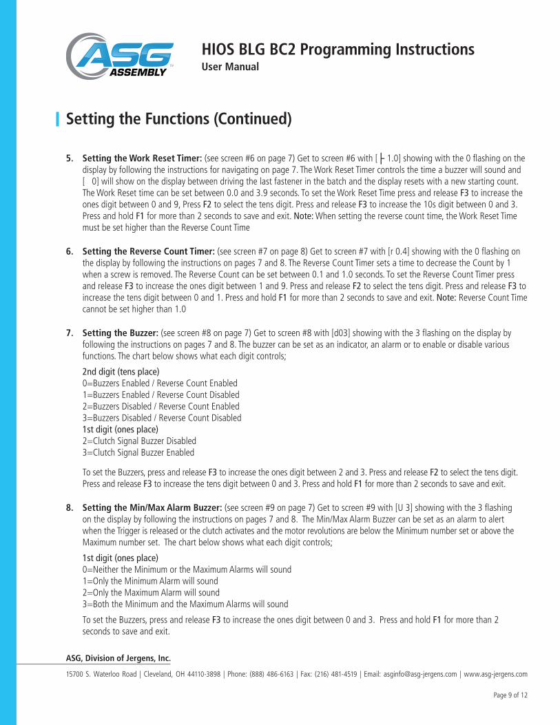
5. Setting the Work Reset Timer: (see screen #6 on page 7) Get to screen #6 with [├ 1.0] showing with the 0 flashing on the display by following the instructions for navigating on page 7. The Work Reset Timer controls the time a buzzer will sound and [ 0] will show on the display between driving the last fastener in the batch and the display resets with a new starting count. The Work Reset time can be set between 0.0 and 3.9 seconds. To set the Work Reset Time press and release F3 to increase the ones digit between 0 and 9, Press F2 to select the tens digit. Press and release F3 to increase the 10s digit between 0 and 3. Press and hold F1 for more than 2 seconds to save and exit. Note: When setting the reverse count time, the Work Reset Time must be set higher than the Reverse Count Time
6. Setting the Reverse Count Timer: (see screen #7 on page 8) Get to screen #7 with [r 0.4] showing with the 0 flashing on the display by following the instructions on pages 7 and 8. The Reverse Count Timer sets a time to decrease the Count by 1 when a screw is removed. The Reverse Count can be set between 0.1 and 1.0 seconds. To set the Reverse Count Timer press and release F3 to increase the ones digit between 1 and 9. Press and release F2 to select the tens digit. Press and release F3 to increase the tens digit between 0 and 1. Press and hold F1 for more than 2 seconds to save and exit. Note: Reverse Count Time cannot be set higher than 1.0
7. Setting the Buzzer: (see screen #8 on page 7) Get to screen #8 with [d03] showing with the 3 flashing on the display by following the instructions on pages 7 and 8. The buzzer can be set as an indicator, an alarm or to enable or disable various functions. The chart below shows what each digit controls;
2nd digit (tens place)0=Buzzers Enabled / Reverse Count Enabled1=Buzzers Enabled / Reverse Count Disabled2=Buzzers Disabled / Reverse Count Enabled3=Buzzers Disabled / Reverse Count Disabled1st digit (ones place)2=Clutch Signal Buzzer Disabled3=Clutch Signal Buzzer Enabled
To set the Buzzers, press and release F3 to increase the ones digit between 2 and 3. Press and release F2 to select the tens digit. Press and release F3 to increase the tens digit between 0 and 3. Press and hold F1 for more than 2 seconds to save and exit.
8. Setting the Min/Max Alarm Buzzer: (see screen #9 on page 7) Get to screen #9 with [U 3] showing with the 3 flashing on the display by following the instructions on pages 7 and 8. The Min/Max Alarm Buzzer can be set as an alarm to alert when the Trigger is released or the clutch activates and the motor revolutions are below the Minimum number set or above the Maximum number set. The chart below shows what each digit controls;
1st digit (ones place)0=Neither the Minimum or the Maximum Alarms will sound1=Only the Minimum Alarm will sound2=Only the Maximum Alarm will sound3=Both the Minimum and the Maximum Alarms will sound
To set the Buzzers, press and release F3 to increase the ones digit between 0 and 3. Press and hold F1 for more than 2 seconds to save and exit.

ASG, Division of Jergens, Inc.
15700 S. Waterloo Road | Cleveland, OH 44110-3898 | Phone: (888) 486-6163 | Fax: (216) 481-4519 | Email: [email protected] | www.asg-jergens.com
Page 10 of 12
Setting the Functions (Continued)
Additional/Common Functions
HIOS BLG BC2 Programming InstructionsUser Manual
9. Viewing the Cycle Totals: (see screen #10 on page 8) Get to screen #10 with [L00] showing on the display. These numbers indicate the total number of cycles resulting in a clutch activation whether the Count is On or OFF. Running the tool and releasing the trigger before the clutch activates is not counted as a cycle. These numbers can be used to determine when to perform maintenance or to rotate the tool out of service. The picture below shows how to read the numbers. Note: These numbers cannot be adjusted and nothing will appear until after 99,999 Cycles and the maximum will be 9,999,999 Cycles.
10. Adjust Re-Hit Timer. (see screen #11 on page 8) Get to screen #11 with [≡0.5] showing with the 5 flashing on the display by following the instructions on pages 7 and 8. The Re-Hit Timer sets a time period between the clutch shut off and a second or third trigger-pull-clutch-shut-off sequence before an Error / Fail is registered. The Re-Hit timer can be set between 0.0 and 9.9 seconds. To set the Re-Hit Timer, press and release F3 to increase the ones digit between 0 and 9. Press and release F2 to select the tens digit. Press and release F3 to increase the tens digit between 0 and 9. Press and hold F1 for more than 2 seconds to save and exit. Note: the Re-Hit Timer functions only when the green Pass LED is lit upon a fastener rundown.
1. Reset the Count: If it becomes necessary to terminate the assembly process before all fasteners have been installed, the count can be reset to the starting number at any time. To reset the count, press and hold F3 for more than 2 seconds. The word HIOS will scroll across the display and the display will reset to the starting count.
2. Exiting the User Interface: (exiting also saves any changes made to the values) The User Interface can be exited at any particular point without scrolling through the remaining screens. Example: You are at the Count screen and you confirmed that the count is set at 5. To exit (and save any changes) press and hold F1 for more than 2 seconds. The next screen will appear briefly, the buzzer will beep twice (if enabled) and the word HIOS will scroll across the display. The current count will then show and the tool is ready to operate.

ASG, Division of Jergens, Inc.
15700 S. Waterloo Road | Cleveland, OH 44110-3898 | Phone: (888) 486-6163 | Fax: (216) 481-4519 | Email: [email protected] | www.asg-jergens.com
Page 11 of 12
Additional/Common Functions
General Information
HIOS BLG BC2 Programming InstructionsUser Manual
3. Verify Firmware Version: When using a BC-2 tool with optional equipment it may be necessary to verify the firmware version in the tool. The procedure for this is the same as that used to turn the counting functions off. Press and hold F1 for 2+ seconds until [P ] appears. Release the F1 button to see [On ] show on the display.
With [P ] showing on the display, press and release F3 to toggle between [ON ] and [OFF]
With [OFF] showing on the display press and hold F1 for 2+ seconds. The buzzer will beep 3 times and the count screen will show briefly, the word HIOS will scroll across the display, then 2.01 (or current Firmware Version number) will show briefly on the display before it goes blank.
Fastener Count: The fastener count number seen on the display always registers the number of fasteners remaining to complete the assembly.
Counter On/OFF: Remember that when the counter is turned off the driver operates like a normal driver with no error proofing or counting functions.
Minimum/Maximum Revolutions: Remember that the Minimum and Maximum revolutions are the motor revolutions, not the number of revolutions of the bit, or fastener. You may notice a difference in the Maximum revolution numbers when driving fasteners of the same length. This is due to the fact that the clutch has some “slack” caused by its construction. This is the reason you need to drive several fasteners before learning a joint. This may also be the reason for an error on a fastener driven after running the tool in reverse when loosening or removing a fastener.
Because the number of motor revolutions will be greater than the actual rotation of the fastener it is possible to “fine tune” the fastener to be able to detect the presence or absence of a washer or an improper length fastener in the joint
If you are using a screw presenter to pick up the fasteners you should set the Minimum Revolutions high enough so that when the trigger is pulled to align the bit into the head of the fastener to pick it out of the presenter, you don’t generate an error.

ASG, Division of Jergens, Inc.
15700 S. Waterloo Road | Cleveland, OH 44110-3898 | Phone: (888) 486-6163 | Fax: (216) 481-4519 | Email: [email protected] | www.asg-jergens.com
Page 12 of 12
General Information (Continued)
Optional Equipment
HIOS BLG BC2 Programming Instructions User Manual
Work Reset Timer and Reverse Count Timer: When the last fastener in the batch has been driven properly, the green (Pass) LED is lit, the Buzzer beeps (if enabled), the Maximum Revolutions show on the display briefly, then a 0 is seen before the count is reset to the starting count. The Work Reset Timer controls how long the green LED stays lit, the buzzer beeps, and 0 remains on the display before the counter resets to the starting count.
The Reverse Count Timer sets a time period where removing a fastener will increase the count shown on the display by one. After this time period, removing a fastener will not affect the count.
It is not necessary to set the Reverse Count Timer to use the Work Reset Timer but it is necessary to set the Work Reset Timer to use the Reverse Count Timer. In order properly identify the removal of any screw in the batch, the Work Reset Timer must be set Higher than the Reverse Count Timer. Otherwise removing the final screw in the assembly will not be recognized and the count will not be increased, but will be reset.
Example: There are 5 screws in the batch, when the two timers are set properly and 4 fasteners are driven correctly with the count showing 1, driving and removing the final fastener will reset the count to 1. When the two timers are set improperly and 4 fasteners are driven correctly with the count showing 1, driving and removing the final fastener resets the count to 5.
Re-Hit Timer: In some applications it may be desirable to pull the trigger a second or third time after the initial clutch shut off to properly clamp a gasket or lock washer. Setting the Re-Hit timer will allow this practice without registering an error, lighting the Red (Fail) LED or sounding the buzzer.
The BLG BC2 tools perform the counting and Error Proofing functions as stand-alone units. With the options below it is possible to add I/O capability, data capturing capability and the ability for process control by interfacing with a PLC or other controls.
• #65665 BLG BC2 I/O Cable with sample software
• #65664 BLG-IO-Pro 1I/O Box. (requires #65665 I/O cable)
ESD Properties. BLG tool Housings are constructed with Anti-Electrostatic Resin.The surface resistance is less than 3x10¹² Ω
RoHs BLG Tools are RoHs Compliant