guidelines for stormwater harvesting on melbourne water …ivwater.com.au/stormwater/mwc...
TRANSCRIPT
Guidelines for stormwater harvesting on Melbourne Water drainage assets
Design, construction and maintenance of diversion
structures
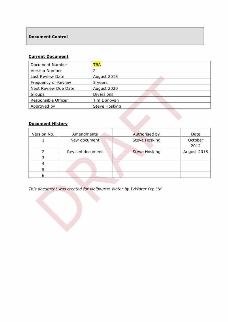
Document Control
Current Document
Document Number TBA
Version Number 2
Last Review Date August 2015
Frequency of Review 5 years
Next Review Due Date August 2020
Groups Diversions
Responsible Officer Tim Donovan
Approved by Steve Hosking
Document History
Version No. Amendments Authorised by Date
1 New document Steve Hosking October
2012
2 Revised document Steve Hosking August 2015
3
4
5
6
This document was created for Melbourne Water by IVWater Pty Ltd
1 Melbourne Water Guidelines for stormwater harvesting on Melbourne Water drainage assets
Section 1 - Introduction 4
Where the urban storm water harvesting can occur 6
Section 2 – Guidelines overview 8
General 8
Typical functional requirements for diversion structures 8
Guidelines structure 9
Asset Ownership 9
Safety in Design 10
Low- flow hydrology and environmental flow requirements 11
Maintenance flows and self-cleansing velocities allowance 13
Low flows quantification and assessment 14
Section 3 - Hydraulic assessment requirements 15
General 15
Hydraulic impact assessment 15
Requirements for hydraulic impact assessment 16
Adjustment and calibration 17
Expansion and Contraction hydraulic losses coefficients 21
Effect of benching on local hydraulic losses in diversion structures 23
Section 4 - Requirements for construction of diversion works 24
General Scope 24
Governing Standards 24
Design Life 25
Concrete exposure classification and loading 25
Concrete durability 26
Concrete joints and waterproofing 26
Formwork 27
Structural Steel and Connections 27
Miscellaneous components 27
Flotation 28
Construction loads 28
2 Melbourne Water Guidelines for stormwater harvesting on Melbourne Water drainage assets
Excavation 28
Earthworks 28
Backfill Material Specification 29
Access covers, step irons and ladders requirements 30
Weepholes 31
Pipe penetrations 31
Protection of site assets 31
Temporary hoarding and fencing 32
Traffic and Access 32
Security 33
Services 33
Site condition and maintenance 34
Risks Assessment 35
Site Environmental Management plan 35
Cultural and Heritage Requirements 37
Assets Handover on completion of construction 37
Special Melbourne Water requirements 41
Section 5 - Operational & maintenance requirements 43
General 43
Minimum size of diversion pipeline 43
Base/low flows and self-cleansing velocities allowance 43
Flow isolation devices 44
Maintenance frequency 44
Maintenance access 44
Adjustment and Calibration 45
Exclusions and Clarifications 45
Section 6 - Licensing and Flow Meter requirements 46
Licence requirement 46
Flow meters 47
Section 7 - Recommended Design Options 49
General 49
3 Melbourne Water Guidelines for stormwater harvesting on Melbourne Water drainage assets
Option 1 50
Option 2 51
Alternative Designs 53
Section 8 - Abbreviations and References 54
Abbreviations 54
References 55
Section 9 - Appendices 57
Appendix 1 Boundary shear stress calculations for maintenance flows 57
Appendix 2 Design drawings 57
4 Melbourne Water Guidelines for stormwater harvesting on Melbourne Water drainage assets
Stormwater has been identified as a relatively untapped water resource with
potential to be utilised more productively to substitute existing demands on potable
water supplies and to meet the water needs of new developments. Also, use of
stormwater is a prerequisite for the protection or restoration of urban waterways.
The Government has recognised that urban stormwater is a potential resource to be utilised
in favour of potable supply for purposes such as irrigation of race courses, golf courses,
sporting ovals and public parks and gardens. This recognition was reinforced in the Central
Region Sustainable Water Strategy.
The Government has adopted the following allocation rules for stormwater in urban areas as
referred to in the Central Region Sustainable Water Strategy 2006:
If stormwater is flowing to the sea via a drain, all of the stormwater may be harvested
If stormwater is flowing to a stream from an existing development, assume up to 50 per
cent of existing stormwater can be harvested for consumptive use and 50 per cent is
reserved for the environment. If there is a scheme to harvest more than 50 per cent of
the resource a study is required to assess the implications for the environment
If stormwater is generated from a new development, all of it is available for consumption
with the aim of the development having no impact on catchment run–off
All diversions from waterways will continue to require a Section 51 licence under the
Water Act 1989.
Stormwater proposals must be considered in the context of the entire catchment,
recognising the intrinsic value of rainfall in replenishing surface water flows and
groundwater recharge and with consideration towards the environmental and
social/aesthetic values of urban waterways.
Availability of water will vary from catchment to catchment depending on a range of issues
including:
Catchment characteristics (level of urbanisation, environmental significance of waterways
within the catchment)
Receiving environment (bay, estuary, freshwater system)
Existing demands (urban and rural).
Section 1 - Introduction
5 Melbourne Water Guidelines for stormwater harvesting on Melbourne Water drainage assets
The frequent discharge of polluted stormwater has been implicated as a major driver of
stream degradation (Walsh et al., 2005). Reducing the frequency and volume of stormwater
delivered to receiving waters is thus a prerequisite for their protection or restoration (Walsh
et al., 2012). However, in some systems stormwater plays an important part in providing
water for flow–stressed rivers. Therefore, any proposals to harvest stormwater must
consider the implications for river health.
Proposals for stormwater use need to consider both the quality and quantity of stormwater
extraction and will therefore require a case by case assessment of the impacts on each of
these areas to ensure that extraction is sustainable.
Melbourne Water approval must be obtained for stormwater harvesting projects if the
connection is to a drain, watercourse or open channel controlled by Melbourne Water.
Licenses for the take and use of water and associated works components must be in place
prior to works or extraction.
As the licensing authority and waterway manager for urban waterways within the Melbourne
region, Melbourne Water has developed draft guidelines for stormwater harvesting and is
continuing to develop principles and rules relating to the volume, rate of harvest and
location of stormwater harvesting. These rules and principles form an important part of the
overall allocation framework for stormwater in this region.
To assist stormwater harvesting proponents Melbourne Water has developed standard
drawings and associated technical guidelines for the design, construction and maintenance
of diversion structures for stormwater harvesting on Melbourne Water assets. These
drawings and guidelines will:
assist proponents and applicants in developing a suitable design likely to be supported by
Melbourne Water
ensure that Melbourne Water’s operational and environmental requirements are met and
the outcome is therefore consistent with our stormwater harvesting principles.
Melbourne Water’s basic principles for diversion structures:
To pass required base flows downstream to receiving waterways where they are
providing for ecological benefits
To minimise any interface and impact on existing Melbourne Water drainage assets
to prevent adverse maintenance / operation conditions within the Melbourne Water
drainage assets
to prevent any adverse impact on the hydrologic function of the waterway, channel or
pipeline
to promote access to stormwater during rain events and higher flow periods.
6 Melbourne Water Guidelines for stormwater harvesting on Melbourne Water drainage assets
Where the urban storm water harvesting can occur
Stormwater can only be harvested within urban areas where significant development has
occurred resulting in increased water run off into drains and waterways above what would
naturally occur in the catchment if still undeveloped. To meet the criteria for harvesting,
proposals need to be within the Urban Growth Boundary (Port Phillip & Western Port) as
defined in the Melbourne 2030 strategic document and contained in council planning
provisions.
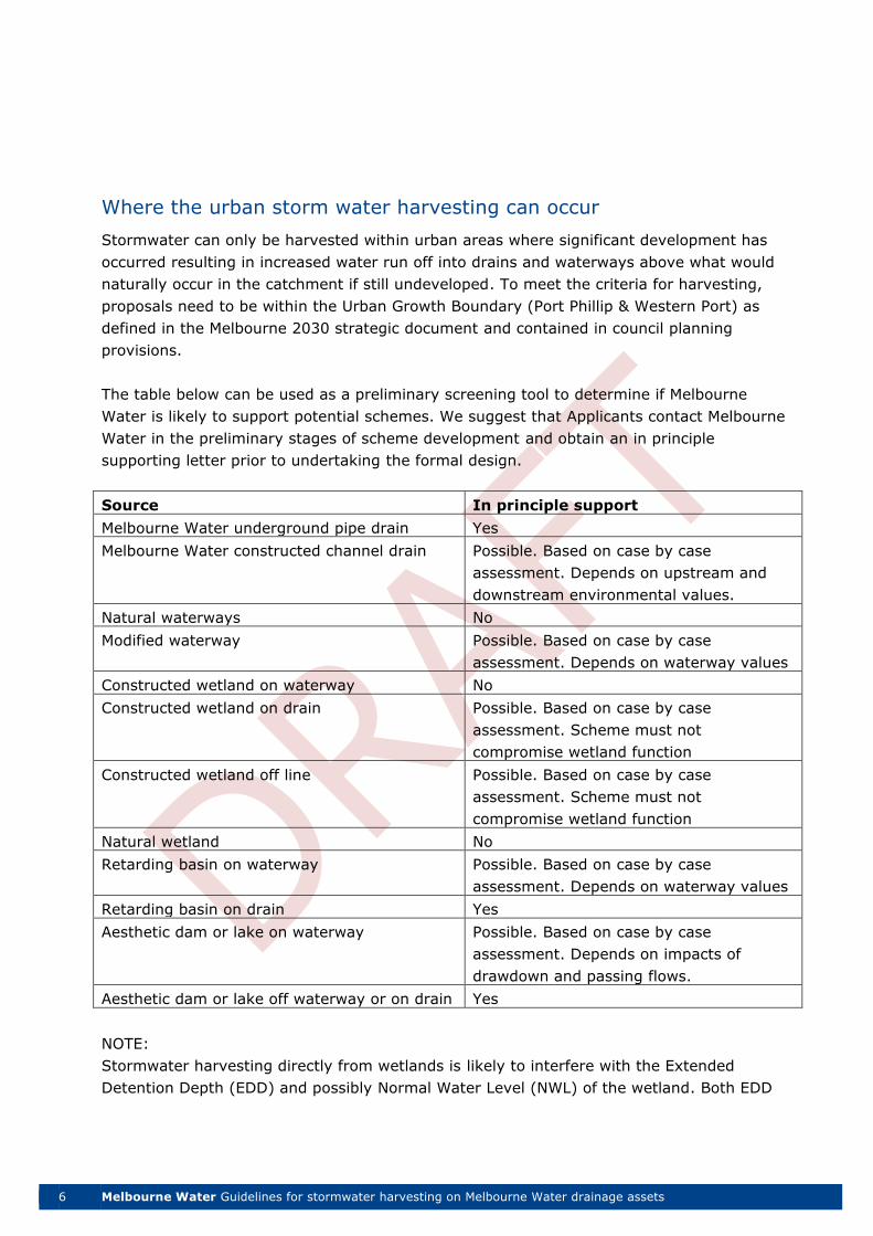
The table below can be used as a preliminary screening tool to determine if Melbourne
Water is likely to support potential schemes. We suggest that Applicants contact Melbourne
Water in the preliminary stages of scheme development and obtain an in principle
supporting letter prior to undertaking the formal design.
Source In principle support
Melbourne Water underground pipe drain Yes
Melbourne Water constructed channel drain Possible. Based on case by case
assessment. Depends on upstream and
downstream environmental values.
Natural waterways No
Modified waterway Possible. Based on case by case
assessment. Depends on waterway values
Constructed wetland on waterway No
Constructed wetland on drain Possible. Based on case by case
assessment. Scheme must not
compromise wetland function
Constructed wetland off line Possible. Based on case by case
assessment. Scheme must not
compromise wetland function
Natural wetland No
Retarding basin on waterway Possible. Based on case by case
assessment. Depends on waterway values
Retarding basin on drain Yes
Aesthetic dam or lake on waterway Possible. Based on case by case
assessment. Depends on impacts of
drawdown and passing flows.
Aesthetic dam or lake off waterway or on drain Yes
NOTE:
Stormwater harvesting directly from wetlands is likely to interfere with the Extended
Detention Depth (EDD) and possibly Normal Water Level (NWL) of the wetland. Both EDD
7 Melbourne Water Guidelines for stormwater harvesting on Melbourne Water drainage assets
and NWL are vital for the ongoing viability of the planted marshes which provide the tertiary
treatment in wetlands. Consequently, in most cases harvesting from wetlands is unlikely to
be supported unless it can be demonstrated by the applicant that the scheme will not
adversely impact on the wetlands treatment, environmental or aesthetic functions.
Stormwater harvesting could be acceptable from wetland outfall pits where it does not
affect the EDD or NWL in the wetland and will provide flows that have a degree of primary,
secondary and tertiary treatment (litter, sediment and nutrient treatment). The discharge
from the outfall structure can be directed to an offline pump well with the necessary
consideration for base flows to the ‘receiving waters’.
For further information on requirements for stormwater harvesting please refer also to
Melbourne Water’s Guidelines for Stormwater harvesting available on our website
http://www.melbournewater.com.au/Planning-and-building/Forms-guidelines-and-standard-
drawings/Documents/Stormwater-harvesting-guidelines.pdf
8 Melbourne Water Guidelines for stormwater harvesting on Melbourne Water drainage assets
General
This document is designed to provide proponents and engineering practitioners with
guidance on Melbourne Water’s requirements and recommended options for the
design, construction, operation and maintenance of diversion structures for
stormwater harvesting constructed on Melbourne Water (MWC) drainage assets.
Design and construction of stormwater diversion structures consistent with these guidelines
and standard drawings will enable a smoother licensing and approval process. Variation to
these requirements will be considered on a case by case basis but the proposed design must
be able to demonstrate how it meets the overarching principles in respect to hydraulic
impacts, maintenance, passing flows, etc.
Typical functional requirements for diversion structures
1. Allow for the reliable diversion of designed flow rates and volumes to the
usage/treatment/storage component
2. Uniform diversion rate control – e.g. there should not be a significant increase in the
flow to treatment/storage component during the overflow
3. The hydraulic impact of the new diversion structure on the existing drainage system
should be minimal
4. The operation should be fully automatic where feasible (e.g. no need for manual
interference during operation)
5. The design should avoid any complication likely to lead to unreliable performance (e.g.
no moving parts)
6. The chamber should be self-cleansing with minimal risk of blockage
7. It should have minimum maintenance requirements
8. It should allow safe access for inspection, maintenance and cleaning
9. Allowance on the diversion pipe for flow calibration and metering
10. Structural integrity of the existing drainage system must not be compromised
11. It should not be in operation until the prescribed flow is being passed through
(environmental and/or self-cleansing flows)
12. Diversion structures should have the ability to be isolated or shut off in case of
maintenance requirement or pollution incident.
Section 2 – Guidelines overview
9 Melbourne Water Guidelines for stormwater harvesting on Melbourne Water drainage assets
Guidelines structure
These Guidelines consist of three essential parts:
1. Introduction and overview
a. Assets ownership
b. Safety in Design requirements
c. Low flows requirements
2. Detailed Requirements
a. Hydraulics assessment
b. Construction
c. Operation & Maintenance
d. Licensing and flow meters
3. Recommended options including drawings.
These guidelines should be read in conjunction with other relevant Melbourne Water
standard drawings and example construction specifications contained in the MWC Land
Development Manual at: http://melbournewater.com.au/Planning-and-
building/Pages/planning-and-building.aspx
Asset Ownership
Commonly in stormwater harvesting proposals the diversion of stormwater from the
Melbourne Water drainage system will require construction of an appropriate diversion
structure within the Melbourne Water asset. Most schemes will require a manhole chamber
to be incorporated in the design and upon completion the structure will be an on-line
component of the drainage system.
Diversion structures (DS) for stormwater harvesting constructed on Melbourne Water
(MWC) drainage assets must be constructed in accordance with Melbourne Water
requirements. The Diversion structure once completed will become a MWC asset following
the successful commissioning and defects liability/proofing by the proponent/contractor.
Ongoing responsibility for the structure and maintenance will rest with Melbourne Water
unless a separate maintenance agreement is entered into. Licensing fees may incorporate a
maintenance fee to cover costs of ongoing inspections and maintenance or alternatively
licence conditions may require the licensee to meet the direct costs of MW maintenance
undertaken on the diversions structure. Any future access or works must be undertaken in
accordance with Melbourne Water requirements and approvals.
The scheme proponent / licence holder will be responsible for the offtake / diversion pipe
and all other harvesting works components downstream of the Diversion structure.
10 Melbourne Water Guidelines for stormwater harvesting on Melbourne Water drainage assets
Additional information on works licensing can be obtained from MWC Diversion Management
team at 131 722.
Safety in Design
Under The Victorian Occupational Health and Safety Act 2004 introduced a duty for any
person who designs a building or structure for use as a workplace. This duty requires
designers of workplace building or structure to ensure that the building or structure is
designed, so far as is reasonably practicable, to be safe and without risk to people using it
as a workplace for the purpose for which it was designed.
Designers under Section 28 include persons who design buildings or structures or part of a
building or structure in the course of undertaking their profession, trade or business. The
Section 28 duty does not apply to clients directly but encourages close collaboration
between the designer and client on health and safety aspects of the design.
This approach consists of Preliminary Hazard Analysis and Systematic Risk Management.
The Preliminary Hazard Analysis should take place as early as in the Pre-design Phase
and continues through the Conceptual or Schematic Design Phase to identify any hazards
that may arise from the design and the intended use of the building or structure (in-scope
hazards of Section 28). The hazards are grouped into five broad categories and presented as
Framework for Hazard Analysis:
siting of the building or structure,
high consequences hazards,
systems of work,
environment, and
incident mitigation.
The Systematic Risk Management is a process to determine whether recommendations in
the technical or engineering standards, industry guidelines or the requirements of the
Building Code of Australia (BCA) can be applied as suitable solutions to the in-scope hazards.
For the hazards that there are no suitable solutions found in Standards, guidelines or the
BCA, or if there are conflicting standards, a proper risk assessment should be conducted in
order to develop design options.
11 Melbourne Water Guidelines for stormwater harvesting on Melbourne Water drainage assets
As part of its assessment of the stormwater harvesting application Melbourne Water will ask
the proponent to provide evidence that an appropriate Safety in Design assessment has
taken place.
More information on the Victorian Occupational Health and Safety Act 2004 requirements is
available on the Worksafe VIC website http://www.worksafe.vic.gov.au/laws-and-
regulations/occupational-health-and-safety
Low- flow hydrology and environmental flow requirements
Under the Water Act 1989, Melbourne Water is the designated caretaker of river health for
the Port Phillip and Westernport region, and has responsibility for waterway management,
major drainage systems and floodplain management and the management of the
environmental water reserve. As the waterway, drainage and floodplain authority for the
Port Phillip and Westernport region, Melbourne Water is a statutory referral authority under
the Planning and Environment Act 1987 for planning applications that may affect
waterways. Melbourne Water therefore has responsibility for ensuring that the rivers,
wetlands and estuaries within the Port Phillip and Westernport region are protected and
improved on behalf of the community.
The Port Phillip and Westernport region spans more than 12,800sqkm, with more than
24,000km of rivers, creeks and estuaries and a range of natural and constructed wetlands
across the Werribee, Maribyrnong, Yarra, Dandenong and Westernport catchments and
contains a variety of waterways, from iconic rivers such as the Yarra to local wetlands, such
as the Edithvale-Seaford Wetlands, that provide a haven for a variety of animals and plants
to breed and thrive.
The Healthy Waterways Strategy (HWS) document
http://www.melbournewater.com.au/aboutus/reportsandpublications/key-
strategies/pages/healthy-waterways-and-stormwater-strategies.aspx outlines the role
Melbourne Water will play, in partnership with the community, our customers and
stakeholders, in managing rivers, estuaries and wetlands in the Port Phillip and Westernport
region to ensure their value to the community is protected and improved.
Some of the targets and objectives outlined in the HWS are:
Continuing to build knowledge and to ensure environmental flow regimes in urban
waterways are improved through the sustainable management and licensing of
stormwater
12 Melbourne Water Guidelines for stormwater harvesting on Melbourne Water drainage assets
Developing frameworks for the sustainable allocation of all sources from an
environmental water perspective
Environmental water management shall be robust under all water availability
scenarios
Assess new diversion applications as well as applications for trade or transfer to
ensure catchment allocation caps are not exceeded
Promote and manage stormwater harvesting schemes consistent with government
objectives and refinement of policy
The flow regime is of fundamental importance to the ecology of streams and its components
influence stream structure and function. Stream biota have evolved to depend on natural
flow regimes and there is widespread agreement that natural flow regimes are essential to
the ecological integrity of streams (Poff et al., 1997).
Many human activities alter natural flow regimes with urban land use being one of the most
striking alterations. Urbanisation most commonly increases the frequency and magnitude of
peak flows in response to rain events, resulting in an increase in the annual runoff volume.
In addition to altering high-flow hydrology, urbanisation changes low-flow hydrology, albeit
with a less consistent response. Covering the landscape with impervious surfaces (e.g. roofs
and roads) reduces infiltration, which consequently decreases contributions to baseflow and
thus to low-flow condition in receiving waterways.
The changes to hydrology associated with urbanisation are a primary degrader of stream
ecosystems (Walsh et al., 2005). The protection and restoration of urban streams requires
approaches to urban stormwater management which will not compromise remaining
environmental values and aim to restore or preserve appropriate flow regimes (in addition
to water quality). To ensure an equitable balance between protecting critical instream flows
and stormwater harvesting can be achieved, MWC need to ensure that stormwater
harvesting across the region is assessed and controlled against objective measures of
impacts on low-flow regimes.
Many harvesting schemes propose to divert low-flows flows from drains or streams outside
of wet weather events. Such proposals do not strictly fit the definition of stormwater
harvesting and may not be supported by Melbourne Water on the basis that:
1. Diverting low- flows from drains or streams exacerbates the reduction in low-flows
caused by urbanisation.
2. The schemes rely less on the harvesting of wet-weather stormwater flows; the flows
that degrade urban stream ecosystems and often cause flooding.
3. The practice precludes future opportunities to successfully restore urban streams.
MWC in partnership with Melbourne University’s Waterway Ecosystem Research Group has
sourced gridded rainfall-runoff data (Australian Water Availability Project;
13 Melbourne Water Guidelines for stormwater harvesting on Melbourne Water drainage assets
http://www.csiro.au/awap/) to predict regional low-flow hydrology in the Port Phillip and
Westernport region. These predictions provides an estimate of pre-development low-flows in
urban streams which can be used to derive catchment-specific passing flow thresholds for
stormwater harvesting in urban areas.
As part of its assessment of stormwater harvesting applications, MWC will use these
predictions to determine a low-flow threshold for each application. Any urban related flow
diversion scheme will only be allowed to divert water in excess of these modelled low-flows.
Applicants should contact Melbourne Water in the preliminary stages of scheme
development so that the low-flow threshold can be determined for input into the detailed
design of the scheme and diversion offtake.
Melbourne Water will adopt these low flows as minimum flow triggers in stormwater
harvesting schemes.
.
Maintenance flows and self-cleansing velocities allowance
For all new diversion structures constructed on Melbourne Water drainage assets, allowance
should be made to pass low/base flows through the system both prior to and during times
of flow diversion in order to avoid sediment deposition and associated maintenance
problems in the drainage network.
The minimum self-cleansing velocities for the design of these flows must be calculated on a
case by case basis using the boundary shear stress approach as described in these design
guidelines. These calculations shall demonstrate that the design solution allows for the
continuation of base flows through the system and that these flows produce the boundary
bottom shear stress equal to or exceeding the pre-set minimal boundary bottom shear
stress of τ ≥ 1.5 Pa. More information on the minimal boundary bottom shear stress
calculations is provided in Appendix 1 of these guidelines.
Melbourne Water at its discretion may accept reduced requirements for the maintenance flow
in the Diversion Structure design if it can be demonstrated that sufficient self-cleansing
velocities are generated in the downstream section on the main drainage line as a result of
additional inflows into the drainage system from other contributing drains in close proximity.
14 Melbourne Water Guidelines for stormwater harvesting on Melbourne Water drainage assets
Low flows quantification and assessment
To assist stormwater harvesting proponents Melbourne Water upon the receipt of an
application and supporting technical data will determine the case - specific low flow
threshold using the CSIRO’s gridded rainfall-runoff predictions (AWAP). These flows will
then be compared to the maintenance flow requirements estimate and in most cases – the
largest number adopted as a minimum flow trigger for stormwater harvesting diversion.
15 Melbourne Water Guidelines for stormwater harvesting on Melbourne Water drainage assets
General
A diversion structure as part of a stormwater harvesting system receiving water from
Melbourne Water drainage assets should be designed to:
Collect the agreed volume of urban runoff from the contributing catchment(s). The
volume of water permitted for collection should be as per requirements of the diversion
license issued by Melbourne Water.
Make allowance for low/base flows to continue through the system prior to and at the
time of flow diversion in order to:
avoid sediment deposition and associated maintenance problems in the drainage
network (refer to operational requirements for more detail)
provide for flow requirements in receiving waterways downstream.
Avoid any adverse impact on the hydraulic capacity of the existing drainage system.
Diversion structure design must ensure no negative hydraulic impacts on adjacent
properties when design capacity of the underground drainage system is exceeded during
extreme rainfall events. Negative hydraulic impacts can be classified as increases in flood
levels, overland flows and/or impact on public safety. Where deemed necessary, the
hydraulic impact of proposed installation is to be checked, documented and presented to
Melbourne Water for approval prior to works commencement.
Provide minimal/negligible headloss to the satisfaction of Melbourne Water.
Ensure no increased risk of blockage to Melbourne Water’s drainage assets.
Avoid any increased risk of detrimental impact on flooding of private properties or public
safety.
Hydraulic impact assessment
Base Theory
Calculation of head losses at diversion structures, represented by changes in energy and
hydraulic grade lines, are required to adequately describe flow behavior and assess its
impact on the original hydraulic capacity of the drainage system.
Flow through diversion structures can be relatively complex due to unsteady full and part-
full pipe flow conditions in stormwater drainage systems. Diversion structures are nearly
always larger than incoming and outgoing pipes and the expansion of pipe flows entering
the structure, the flow diversion impact and the effects of downstream water levels create
Section 3 - Hydraulic assessment requirements
16 Melbourne Water Guidelines for stormwater harvesting on Melbourne Water drainage assets
complex flow conditions, with energy losses and local increases in water levels that in
extreme situations could reduce performance and cause overflows.
Complexity comes from the almost infinite variety of conditions that can occur. Some relate
to the system geometry. For a typical diversion structure this can involve:
a) various numbers of pipes entering the structure (1 to 3 or more)
b) the angles of the inlet pipes relative to the outlet pipe in the horizontal plane
c) the various heights of the invert pipes and drops in the structure
d) the pipe diameters and slopes
e) whether incoming pipe inflows are opposed, so that jets will interfere with each other
f) whether jets from inlet pipes are directed into the outlet pipe, or against a wall/weir
g) type of diversion mechanism (e.g. transverse weir, side weir, drop etc.)
h) the size and shape of the structure
i) whether benching or deflectors are placed in the structure.
Also important are flow characteristics, including:
j) the flow rates in the inlet pipes and the diversion flow rate
k) whether the pipes are running full or part-full, supercritical or subcritical
l) the effect of tailwater level and the water level in the pit
m) in the case of junctions with two or more upstream pipes, time-dependent flow ratios, as
contributing hydrographs in upstream pipes pass through the diversion structure.
Requirements for hydraulic impact assessment
The type and geometry of a diversion structure should be selected with due consideration of
its hydraulic impact on the conveyance capacity of the original drainage system for the full
range of expected flows.
Stormwater proponents should contact Melbourne Water’s Asset Management Team in order
to obtain existing asset information to inform the design of a diversion structure.
Based on the assets information available, the following hydraulics parameters should be
established in consultation with Melbourne Water:
Pipe/culvert geometry incl. cross section(s) and gradient(s),
Hydraulic capacity of the original drainage network at the proposed location of diversion
structure (typically Qsystem in m3 /sec),
Energy and Hydraulic grade lines for the original drainage system at/in the vicinity of the
proposed diversion structure,
Governing flow regime in the drainage network at Qsystem (e.g. sub-critical free flow)
17 Melbourne Water Guidelines for stormwater harvesting on Melbourne Water drainage assets
Based on the above parameters the maximum allowable hydraulic impact of the proposed
diversion structure should be determined in consultation between the proponent and
Melbourne Water on a case-by-case basis.
In cases of minimal risk of negative hydraulic impacts to private property and/or public
safety, some localized hydraulic impacts may be acceptable subject to consultation with
Melbourne Water.
In cases of hydraulically sensitive areas where there is tangible risk of negative hydraulic
impacts to private property and/or public safety, the applicant must ensure no negative
hydraulic impacts due to the diversion structure and will be required to demonstrate
through hydraulic modeling how impacts will be mitigated to the satisfaction of Melbourne
Water.
The designer of the proposed stormwater harvesting works will be required to prepare and
submit sufficiently detailed calculations to demonstrate that for the specified range of flows
(typically up to and including the Qsystem ) the hydraulic impact of the proposed installation is
kept within the agreed limits.
These calculations are expected to address both the localised hydraulic impact and the
propagation of this local impact further upstream of the proposed diversion structure to the
extent determined in consultation with Melbourne Water.
Adjustment and calibration
The diversion structure (DS) design should have allowance for further adjustments and
calibration (e.g. base flow passage rates, diversion rates etc.) where practicable.
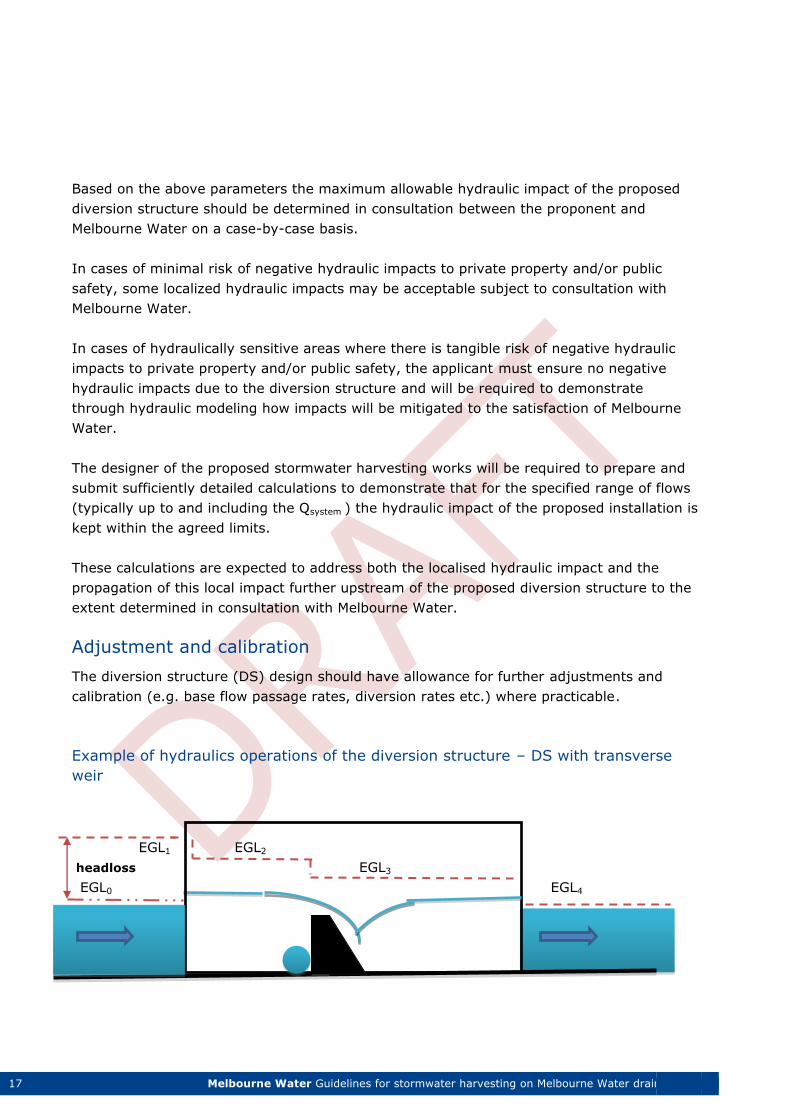
Example of hydraulics operations of the diversion structure – DS with transverse
weir
EGL1 EGL2
headloss EGL3
EGL0 EGL4
18 Melbourne Water Guidelines for stormwater harvesting on Melbourne Water drainage assets
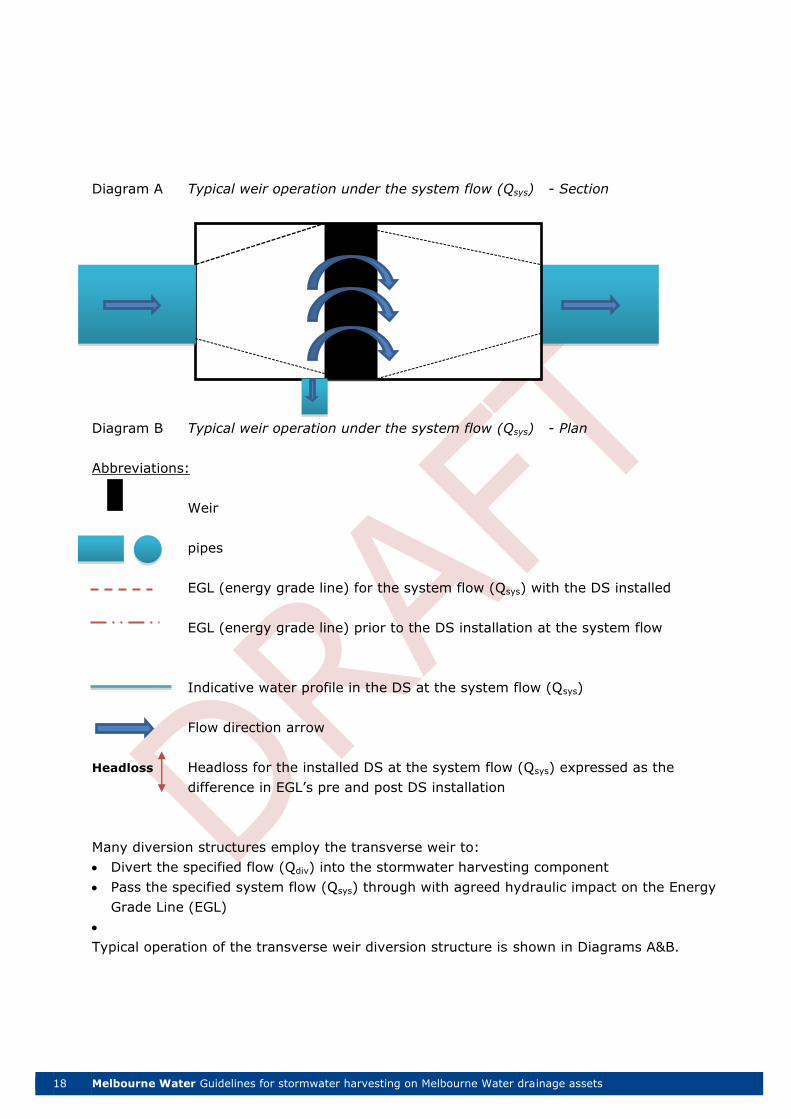
Diagram A Typical weir operation under the system flow (Qsys) - Section
To the harvesting scheme
Diagram B Typical weir operation under the system flow (Qsys) - Plan
Abbreviations:
Weir
pipes
EGL (energy grade line) for the system flow (Qsys) with the DS installed
EGL (energy grade line) prior to the DS installation at the system flow
Indicative water profile in the DS at the system flow (Qsys)
Flow direction arrow
Headloss Headloss for the installed DS at the system flow (Qsys) expressed as the
difference in EGL’s pre and post DS installation
Many diversion structures employ the transverse weir to:
Divert the specified flow (Qdiv) into the stormwater harvesting component
Pass the specified system flow (Qsys) through with agreed hydraulic impact on the Energy
Grade Line (EGL)
Typical operation of the transverse weir diversion structure is shown in Diagrams A&B.
19 Melbourne Water Guidelines for stormwater harvesting on Melbourne Water drainage assets
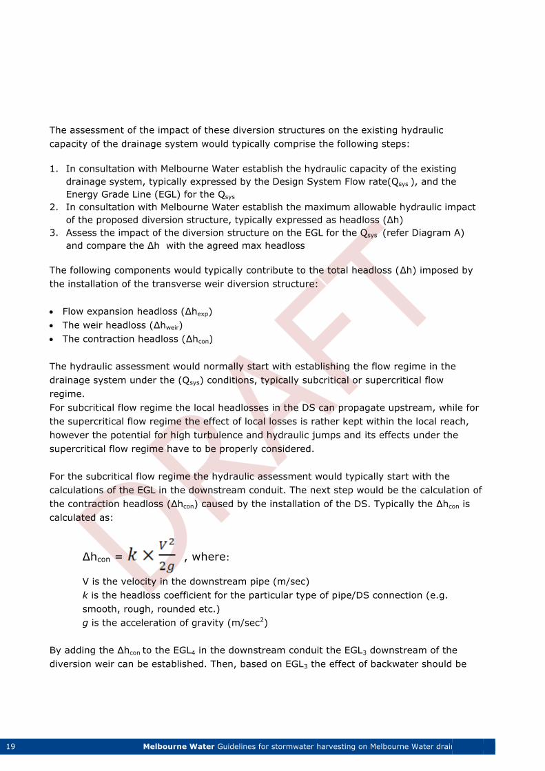
The assessment of the impact of these diversion structures on the existing hydraulic
capacity of the drainage system would typically comprise the following steps:
1. In consultation with Melbourne Water establish the hydraulic capacity of the existing
drainage system, typically expressed by the Design System Flow rate(Qsys ), and the
Energy Grade Line (EGL) for the Qsys
2. In consultation with Melbourne Water establish the maximum allowable hydraulic impact
of the proposed diversion structure, typically expressed as headloss (Δh)
3. Assess the impact of the diversion structure on the EGL for the Qsys (refer Diagram A)
and compare the Δh with the agreed max headloss
The following components would typically contribute to the total headloss (Δh) imposed by
the installation of the transverse weir diversion structure:
Flow expansion headloss (Δhexp)
The weir headloss (Δhweir)
The contraction headloss (Δhcon)
The hydraulic assessment would normally start with establishing the flow regime in the
drainage system under the (Qsys) conditions, typically subcritical or supercritical flow
regime.
For subcritical flow regime the local headlosses in the DS can propagate upstream, while for
the supercritical flow regime the effect of local losses is rather kept within the local reach,
however the potential for high turbulence and hydraulic jumps and its effects under the
supercritical flow regime have to be properly considered.
For the subcritical flow regime the hydraulic assessment would typically start with the
calculations of the EGL in the downstream conduit. The next step would be the calculation of
the contraction headloss (Δhcon) caused by the installation of the DS. Typically the Δhcon is
calculated as:
Δhcon = , where:
V is the velocity in the downstream pipe (m/sec)
k is the headloss coefficient for the particular type of pipe/DS connection (e.g.
smooth, rough, rounded etc.)
g is the acceleration of gravity (m/sec2)
By adding the Δhcon to the EGL4 in the downstream conduit the EGL3 downstream of the
diversion weir can be established. Then, based on EGL3 the effect of backwater should be
20 Melbourne Water Guidelines for stormwater harvesting on Melbourne Water drainage assets
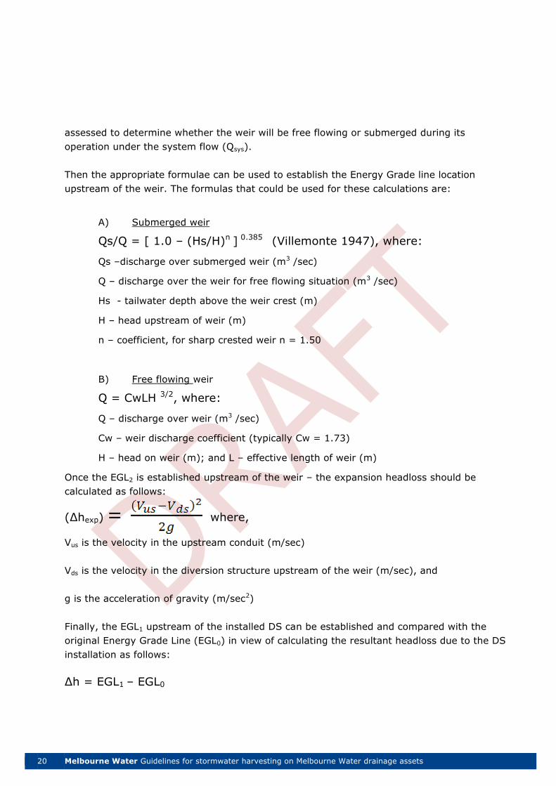
assessed to determine whether the weir will be free flowing or submerged during its
operation under the system flow (Qsys).
Then the appropriate formulae can be used to establish the Energy Grade line location
upstream of the weir. The formulas that could be used for these calculations are:
A) Submerged weir
Qs/Q = [ 1.0 – (Hs/H)n ] 0.385 (Villemonte 1947), where:
Qs –discharge over submerged weir (m3 /sec)
Q – discharge over the weir for free flowing situation (m3 /sec)
Hs - tailwater depth above the weir crest (m)
H – head upstream of weir (m)
n – coefficient, for sharp crested weir n = 1.50
B) Free flowing weir
Q = CwLH 3/2, where:
Q – discharge over weir (m3 /sec)
Cw – weir discharge coefficient (typically Cw = 1.73)
H – head on weir (m); and L – effective length of weir (m)
Once the EGL2 is established upstream of the weir – the expansion headloss should be
calculated as follows:
(Δhexp) where,
Vus is the velocity in the upstream conduit (m/sec)
Vds is the velocity in the diversion structure upstream of the weir (m/sec), and
g is the acceleration of gravity (m/sec2)
Finally, the EGL1 upstream of the installed DS can be established and compared with the
original Energy Grade Line (EGL0) in view of calculating the resultant headloss due to the DS
installation as follows:
Δh = EGL1 – EGL0
21 Melbourne Water Guidelines for stormwater harvesting on Melbourne Water drainage assets
Expansion and Contraction hydraulic losses coefficients1
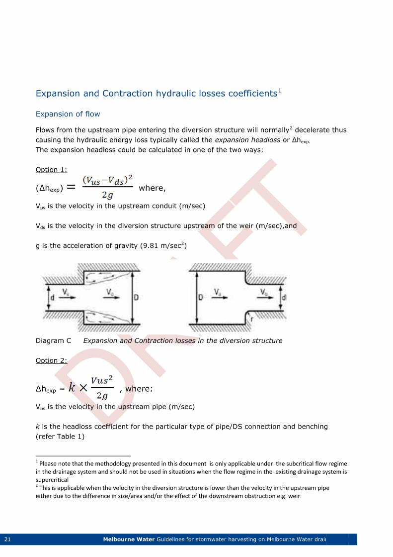
Expansion of flow
Flows from the upstream pipe entering the diversion structure will normally2 decelerate thus
causing the hydraulic energy loss typically called the expansion headloss or Δhexp.
The expansion headloss could be calculated in one of the two ways:
Option 1:
(Δhexp) where,
Vus is the velocity in the upstream conduit (m/sec)
Vds is the velocity in the diversion structure upstream of the weir (m/sec),and
g is the acceleration of gravity (9.81 m/sec2)
Diagram C Expansion and Contraction losses in the diversion structure
Option 2:
Δhexp = , where:
Vus is the velocity in the upstream pipe (m/sec)
k is the headloss coefficient for the particular type of pipe/DS connection and benching
(refer Table 1)
1 Please note that the methodology presented in this document is only applicable under the subcritical flow regime in the drainage system and should not be used in situations when the flow regime in the existing drainage system is supercritical 2 This is applicable when the velocity in the diversion structure is lower than the velocity in the upstream pipe either due to the difference in size/area and/or the effect of the downstream obstruction e.g. weir
22 Melbourne Water Guidelines for stormwater harvesting on Melbourne Water drainage assets
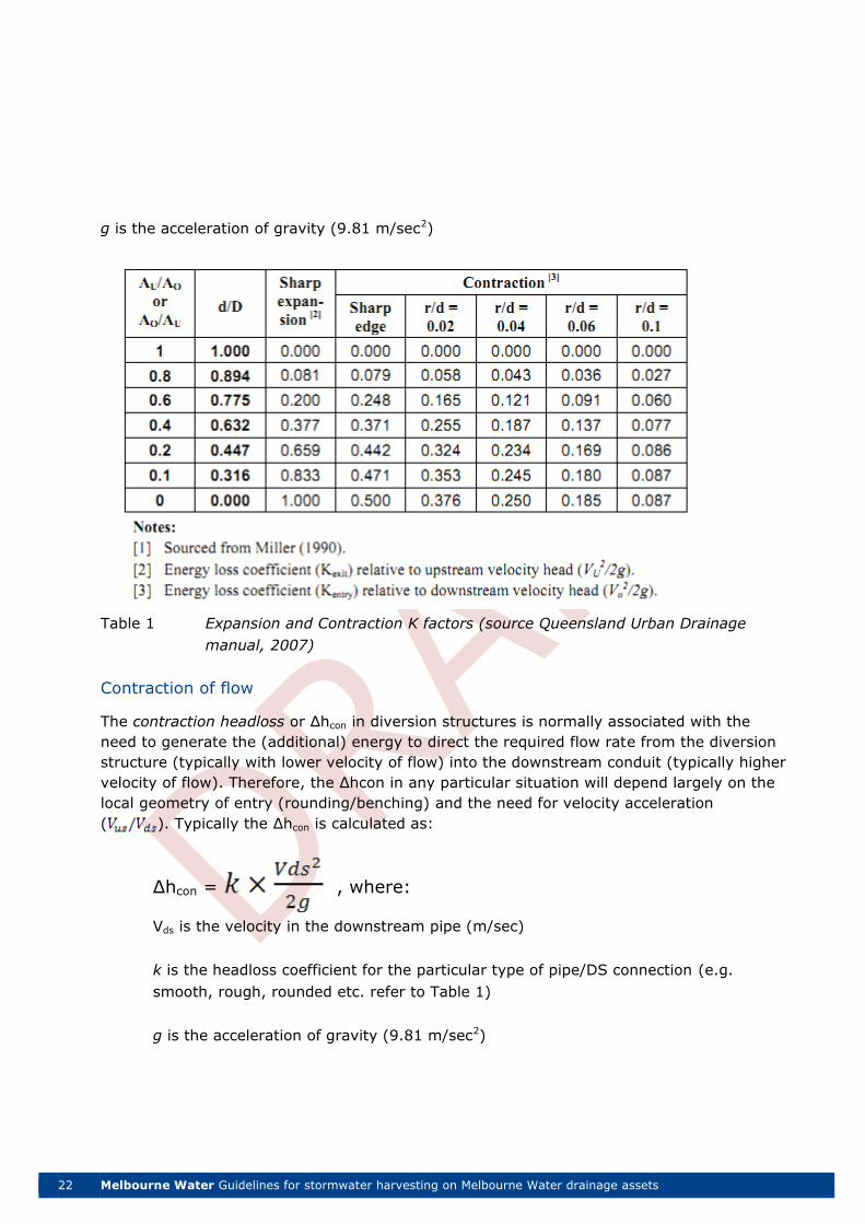
g is the acceleration of gravity (9.81 m/sec2)
Table 1 Expansion and Contraction K factors (source Queensland Urban Drainage
manual, 2007)
Contraction of flow
The contraction headloss or Δhcon in diversion structures is normally associated with the
need to generate the (additional) energy to direct the required flow rate from the diversion
structure (typically with lower velocity of flow) into the downstream conduit (typically higher
velocity of flow). Therefore, the Δhcon in any particular situation will depend largely on the
local geometry of entry (rounding/benching) and the need for velocity acceleration
( ). Typically the Δhcon is calculated as:
Δhcon = , where:
Vds is the velocity in the downstream pipe (m/sec)
k is the headloss coefficient for the particular type of pipe/DS connection (e.g.
smooth, rough, rounded etc. refer to Table 1)
g is the acceleration of gravity (9.81 m/sec2)
23 Melbourne Water Guidelines for stormwater harvesting on Melbourne Water drainage assets
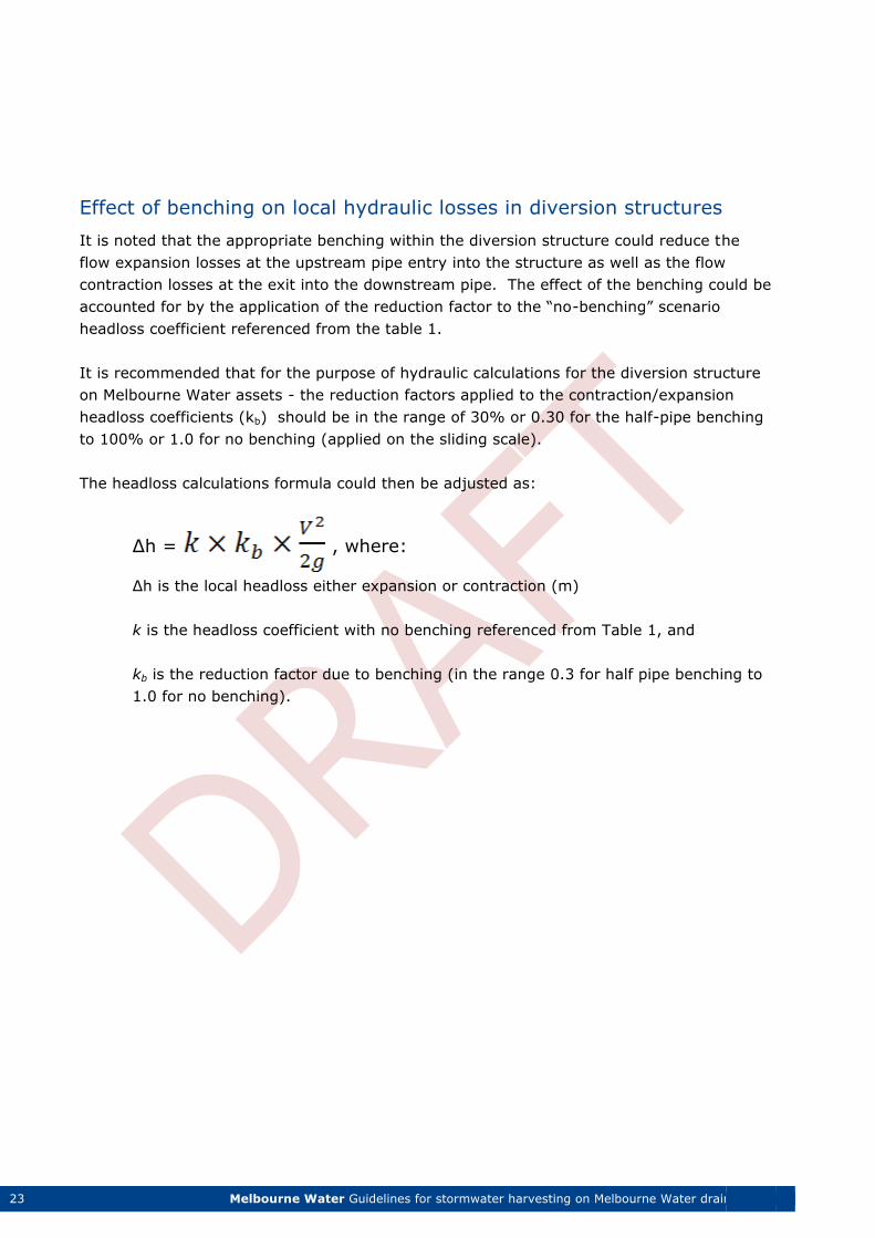
Effect of benching on local hydraulic losses in diversion structures
It is noted that the appropriate benching within the diversion structure could reduce the
flow expansion losses at the upstream pipe entry into the structure as well as the flow
contraction losses at the exit into the downstream pipe. The effect of the benching could be
accounted for by the application of the reduction factor to the “no-benching” scenario
headloss coefficient referenced from the table 1.
It is recommended that for the purpose of hydraulic calculations for the diversion structure
on Melbourne Water assets - the reduction factors applied to the contraction/expansion
headloss coefficients (kb) should be in the range of 30% or 0.30 for the half-pipe benching
to 100% or 1.0 for no benching (applied on the sliding scale).
The headloss calculations formula could then be adjusted as:
Δh = , where:
Δh is the local headloss either expansion or contraction (m)
k is the headloss coefficient with no benching referenced from Table 1, and
kb is the reduction factor due to benching (in the range 0.3 for half pipe benching to
1.0 for no benching).
24 Melbourne Water Guidelines for stormwater harvesting on Melbourne Water drainage assets
General Scope
All works carried out to / on Melbourne Water assets, including diversion structures which
will become the responsibility of Melbourne Water must be undertaken in accordance with
standards outlined in this section.
The scope for construction of diversion structures shall generally include, but not be limited
to:
Site preparation
Site temporary fencing, gates and security
Access roads
Temporary pavement for construction access road
Excavation
Condition /dilapidation survey
Surface treatment/soil stabilisation (if applicable)
Dewatering (if applicable)
Water proofing
Formwork
Reinforcement
Concrete and structural works
Sealing
Spoil disposal
Suitable back filling material
Include the provisions for access stairs, services lift opening and major refurbishment
opening in the roof structure.
Ground level structure provisions for drainage, sumps, pits and bunds.
Services and piping connection valve pits
Soiling, grassing and landscaping
Making good access paths and roads.
Governing Standards
The following Australian Standards shall be deemed to govern requirements for relevant
materials and workmanship:
AS 1319 Safety signs for the occupational environment.
AS 1170 Structural design actions.
Section 4 - Requirements for construction of diversion works
25 Melbourne Water Guidelines for stormwater harvesting on Melbourne Water drainage assets
AS 1345 Identification of the contents of pipes, conduits and ducts.
AS 1939 Degrees of protection provided by enclosures for electrical equipment.
AS 1940 The storage and handling of flammable and combustible liquids.
AS 2700 Colour standards for general purposes.
AS 2845 Water supply - backflow prevention devices
AS 3000 Electrical installations (known as the Australian/New Zealand Wiring Rules).
AS 3500 National plumbing and drainage code.
AS 3600 Concrete Structures.
AS 3996 Access covers and grates
AS 4087 Metallic flanges for waterworks purposes
WSA 01 Polyethylene Pipeline Code.
All work shall meet all the requirements of national and local authorities and shall also be in
accordance with the following in so far as they apply to the work:
Structure Code of Australia
MRWA specification No: 04-03-1
All applicable Australian Standards
Melbourne Water requirements
Local government requirements
Workcover requirements
All Health Authority Requirements
Metropolitan Fire Brigade requirements
the Water Act 1989
Occupational Health and Safety Act
Melbourne Water requirements for confined space entry and permit to works system
The Aboriginal Cultural Heritage Act
Design Life
All diversion structures on Melbourne Water assets should be designed for the following
design life:
Concrete structures 50 years
Pipework 50 years
Mechanical work 25 years
Metal work 25 years
Concrete exposure classification and loading
26 Melbourne Water Guidelines for stormwater harvesting on Melbourne Water drainage assets
Exposure classification - in accordance with table 4.3 in AS 3600
Traffic loading - to W7, T44, HLP 320 and SM 1600 and other relevant design
code and standards
Concrete durability
Minimum concrete strengths and associated minimum nominal concrete cover shall comply
with AS3600. The structures shall be designed to be waterproof from both internal and
external sources. The concrete mix for the structure shall be developed to achieve the
minimum design strength of 32 MPa in accordance with the durability requirements.
Lower strength concrete can be considered for use in non-structural applications (e.g. benching). The concrete properties to be used in the design shall be calculated in
accordance with AS3600.
Consideration shall be given to the effects of shrinkage and creep in concrete structures.
The characteristics of different types and different ages of concrete shall be considered.
These effects shall be included in the ultimate and serviceability limit states using the
appropriate load factors in accordance with AS5100.
Concrete joints and waterproofing
The structure shall be waterproof from both internal and external water. Joints in the
structure shall be made continuous where feasible to minimise areas potentially vulnerable
to water leakage.
Water resisting measures shall be adopted, in particular:
Roof slab to wall construction joints and roof slab construction joints shall be detailed
with suitable bars, hydrophilic seals or similar.
If the base slab is monolithic and integral with the wall for structural reasons, the floor to
wall construction joints shall be detailed as for water-retaining structures.
The diversion structure shall be designed and detailed in accordance with AS3735 and
AS3600. The design and detailing of construction joints shall be such that the number of
construction joints will be as few as practicable. Where significant for design, the locations
of construction joints and the construction sequence shall be clearly indicated on the
drawings.
In terms of construction, the concrete pour length shall be limited by the Contractor to
ensure the structure is fully water proof and suitable to be a water retaining structure.
27 Melbourne Water Guidelines for stormwater harvesting on Melbourne Water drainage assets
Formwork
Generally, the finish to walls and slabs shall be in accordance with AS3610.
Design and construct formwork so that the concrete, when cast in the forms, will have the
required dimensions, shape, profile, location and surface finish. Allow for dimensional
changes, deflections and cambers resulting from the application of prestressing forces (if
any), applied loads, temperature changes and concrete shrinkage and creep.
Formwork shall be watertight and of sufficient strength to prevent excessive deflection
under loads during placement and compaction of fresh concrete.
Structural Steel and Connections
All structural steelwork shall be Australian Steel Sections with minimum Grade 300 and
designed using ultimate limit state method in accordance with AS4100.
The design method adopted shall be clearly stated at the start of the calculations. Unless
otherwise shown, structural bolts shall be designed in accordance with AS 1252. Capacities
of bolts shall be based on the assumption that threads are in the shear plane. Bolts shall be
installed in accordance with AS4100. Lock nuts shall be used in the vicinity of vibrating
equipment.
Where necessary, slotted holes shall be used to allow for thermal expansion and
contraction. All connections shall have a minimum of 2 bolts except for minor connections.
The minimum fillet weld size shall be 6 mm unless otherwise approved by Melbourne Water.
All welding for structural components shall be minimum grade SP in accordance with
AS1554.
All stainless steel components should be grade 316 or equivalent.
Miscellaneous components
All steelwork within the works space must as a minimum be heavy duty galvanised with
appropriate attention to dissimilar metal corrosion; designed to conform to AS4100.
Exposed steelwork, including services supports, access platforms and hand railing, shall be
hot dip galvanised to AS/NZS 4680 “Hot-dip galvanized (zinc) coatings on fabricated ferrous
articles” with an average minimum coating thickness of 85 microns, or an equivalent level
of protection.
Reference should be made to AS2312 “Guide to the protection of structural steel against
atmospheric corrosion by the use of protective coatings”. Durability requirements shall be
28 Melbourne Water Guidelines for stormwater harvesting on Melbourne Water drainage assets
25+ years which is categorised as extra-long term. Atmospheric corrosivity shall be
category C (Medium) which is typical for sewage treatment works.
Flotation
Stability of the structure against flotation shall be checked for all stages of construction and
throughout the service life of the structure based on the design ground water levels and
flood levels.
Construction loads
Permanent forces and effects introduced during construction shall be considered in the
design. Allowance shall also be made for the weight of any false work, plant and any
associated storage/stockpile loading of materials that may be carried by the structure
resulting from the anticipated method or sequence of construction; this includes crane
loads, compaction equipment during backfilling, etc.
Excavation
The excavation shall not extend past the defined works space (other than a nominal agreed
amount to incorporate a temporary shoring system). Provide temporary supports, bracing,
shoring, planking and strutting as required for excavation.
A preferred method of excavation is to bring excavated fill to ground level and finally into a
truck for disposal/stockpiling. Where excavation exceeds the required depth, or
deteriorates, reinstate to the required level and bearing value. Make allowance for
compaction or settlement.
Prepare the excavated final level (i.e. remove materials such as loose material, debris and
organic matter) before constructing ground slabs or load bearing elements.
At practical completion of construction, the final ground surface level shall be reasonably
smooth and uniform, similar to its original state.
Excavation must make allowance for protection of any existing assets. Particular care must
be taken around sensitive and/or aged assets such as brick drains etc.
Earthworks
Compaction standards shall be expressed as a percentage of the materials standard
Maximum Dry Density (MDD (std)) at its optimum moisture content as determined in
accordance with AS1289.
29 Melbourne Water Guidelines for stormwater harvesting on Melbourne Water drainage assets
The required degree of compaction shall be as follows:
95% for fill generally.
100% for a minimum depth of 300mm immediately under concrete slabs and footings
placed on fill or the in-situ subgrade.
Embankments composed of engineered fill and cuts in existing site material shall be
excavated in accordance with recommendation provided by geotechnical investigation report
commissioned by the contractor and/or consultant and approved by Melbourne Water.
Backfill Material Specification
The Contractor shall employ suitable methods to compact backfill of excavation and to
comply with the approved project specification and prevent collapse or settlement. Where
fill is placed around the structure, the fill shall be placed and compacted evenly to prevent
displacement.
Care shall be taken to place and compact the fill evenly around the structure in thin layers,
to avoid unbalanced lateral loading. High compactive effort shall not be used against
structures to ensure damage to the structure is prevented. Particular care must be taken to
adjacent retaining walls. The project specific recommendations on the suitable backfill
should be determined in consultation with Melbourne Water based on a site specific
geotechnical report commissioned by the Contractor/Consultant.
Topsoil
At practical completion of construction, the site topsoil shall support plant life and be safe
for human life, contain organic matter and be free from unwanted matter (i.e. stones over
25mm diameter, clay lumps, weeds and tree roots, sticks and rubbish, material toxic to
plants, etc).
Soil shall be tested in accordance with AS4419. Soil placement shall be by wheel barrow,
conveyor or bucket excavated to avoid excessive compaction.
Spread topsoil on the prepared subsoil and grade evenly making the necessary allowances
to permit the following:
Required finished levels and contours may be achieved after light compaction
Grassed areas may be finished flush with adjacent hard surfaces such as kerbs and foot
paths.
30 Melbourne Water Guidelines for stormwater harvesting on Melbourne Water drainage assets
Compact lightly and uniformly in 150 mm layers. Compact by hand or by light rolling.
Between each layer, cultivate to a depth of approximately 25mm to avoid the formation of
interface problems. Avoid differential subsidence and excess compaction and produce a
finished topsoil surface which has the following characteristics:
Finished to design levels
Smooth and free from stones or lumps of soil
Graded to drain freely, without ponding, to catchment points
Graded evenly into adjoining ground surfaces
Ready for planting.
All backfill and compaction works are to be designed and executed in accordance with the
MRWA specification No: 04-03-1 – Backfill specification.
Access covers, step irons and ladders requirements
General
Access arrangements for the diversion structures shall be in accordance with Melbourne
Water Access Covers, Platforms and Walkways Standard CORP AM S020 version 2, August
2014 and AS1657 – 2013 Fixed platforms, walkways, stairways and ladder – Design,
construction and installation.
Minimum access shaft diameter - 0.90 m
All materials to be Stainless Steel grade 316 or equivalent
All fixing to be Stainless Steel grade 316 or equivalent
Step irons
Step irons and ladders must conform to Melbourne Water Access Covers, Platforms and
Walkways Standard CORP AM S020 version 2, August 2014 AS 1657-2013 and be located
and fixed in the structure in accordance with the approved drawings.
The access step irons must be cast in-situ. Step irons used for other purposes may be
installed in drilled holes using a dry packed mortar or epoxy compound.
All bolts must be placed in the formwork before pouring the concrete. Care must be taken to
ensure that step irons remain in place and are properly aligned after pouring.
31 Melbourne Water Guidelines for stormwater harvesting on Melbourne Water drainage assets
Access covers
All covers must conform to AS 3996-2006 and be Heavy-duty Gatic Type BV or equivalent
and fixed flush with the pavement or finished surface level, or in accordance the Drawings and Tolerances.
The Contractor must prevent distortion of cast iron frames during fixing and replace any
distorted cover or frame. Cast iron covers must be filled with M25 Grade concrete. The identification, cover locating marks and numbering pad must be left exposed.
The covers and frames must be cleaned and greased after completion of the section of the
Works.
Weepholes
Where site conditions require the use of weepholes, they shall be placed in accordance with
Drawing 7251/8/403 in Melbourne Water’s Land Development Manual. The holes must be a minimum diameter of 38 millimetres. The outlets must be clean and flush with the outer
face of the structure.
Weephole formwork must be set in place before concrete is poured. Hollow weephole formwork must be temporarily filled and covered with bituminous paper or plastic film
before pouring to prevent concrete entering the cavity.
Pipe penetrations
Pipe penetration cut-outs should be round holes and should be no larger than the pipe
diameter plus 25mm. Make cuts using a saw with a masonry or diamond grit blade. Do not
use an axe or other impact type tools.
Protection of site assets
The Contractor shall ensure all site assets are protected at all times. Any damage incurred
as a result of works undertaken by the Contractor as part of contract shall be immediately
reported and repaired to the satisfaction of Melbourne Water, at the Contractor’s expense.
Location and protection of all services underground and above ground is the responsibility of
the Contractor and locations shall be verified on site prior to commencing work.
The Contractor shall protect trees and site vegetation at all times during the construction
works. If the Contractor damages vegetation, remedial works must be undertaken to the
satisfaction of Melbourne Water.
32 Melbourne Water Guidelines for stormwater harvesting on Melbourne Water drainage assets
Temporary hoarding and fencing
All works must be enclosed with suitable temporary barriers and protection which prevents
the entry of unauthorised persons onto the site, and prevent injury, damage, vandalism or
theft. The Contractor is responsible to supervise openings and access points to the Works
during working hours and to ensure the safety and security of the Works during non-
working hours
The Superintendent may require additional barriers and protection at no additional cost to
Melbourne Water.
Melbourne Water may require additional barriers and protection be provided. Barriers and
protection adjacent to roads and paths shall be fitted with night reflectors, orange plastic
bunting and lighting as required for safety.
Barrier types shall include as appropriate:
Chain mesh fencing, not less than two metres high
Fluorescent para-webbing
Temporary rails and bunting, one metre high
Screens of continuous plastic sheeting, taped edges, to restrict dust and moisture
Existing fences, if approved by the Superintendent
Other suitable barrier types approved by the Superintendent.
Traffic and Access
The Contractor shall prepare a Traffic Management Plan for review by Melbourne Water. The
traffic management plan shall identify all disruptions to traffic movement and public access
to the site and adjacent properties and all safety barriers and equipment to be used.
The traffic management plan should also address issues regarding access and loading. The
traffic management plan shall be submitted to the local council’s traffic management
department. Works shall not commence until the traffic management plan has been
approved.
Adjacent roads, paths and land:
The Contractor will be responsible to:
33 Melbourne Water Guidelines for stormwater harvesting on Melbourne Water drainage assets
Provide and maintain continuous access to adjacent properties and public areas for
pedestrians and vehicles. Do not close or obstruct any road or path unless required by
the approved works permit and carried out in accordance with the requirements of the
relevant authorities.
Make arrangements with Melbourne Water and other relevant authorities / land owners
for access to and from the site for personnel, goods and materials, and constructional
plant and equipment. Provide required temporary roads, crossings over existing roads
and paths, in accordance with the requirements of the relevant authorities, and remove
when no longer required.
Provide traffic control equipment as required from time to time or by the relevant
authority. Traffic control equipment shall include vehicle barricades, signs, traffic lights
and the like.
Ensure all existing infrastructure to be retained is protected from damage.
Ensure all temporary access roads are dismantled at the completion of construction
works and the affected surfaces reinstated to the standards acceptable by Melbourne
Water and the landowner.
Security
The Contractor shall be responsible for all activities on the Site including providing access
for authorised persons and restricting the access of unauthorised persons. The Contractor
shall take all necessary precautions to secure the site, works, materials, plant and
equipment during working and non-working hours from the date of commencement on-site
to 4.00pm on the Date of Practical Completion.
Services
Identification and protection of existing services.
It is the responsibility of the Contractor to carry out all investigations necessary (including
utilising Dial Before You Dig Melbourne One Call Service and physically detecting services on
site using suitable electronic equipment) to locate and mark the location of all services
within the works area and to retain and protect those services throughout the Contract
period.
Any damage to existing services caused by the Contractor must be repaired or rectified at
the Contractor’s expense to the satisfaction of Melbourne Water and the responsible
authority.
The Contractor must not excavate by machine within 1m of existing underground services.
34 Melbourne Water Guidelines for stormwater harvesting on Melbourne Water drainage assets
Continuity of Services
No services shall be interrupted unless agreed in writing by Melbourne Water or the service
provider
Telephone services shall be maintained in continuous operation. Where service disruption is
required, disconnect services at nearest stop valve, or switchboard, before cutting or
opening service pipes and conduits. Provide temporary or permanent sealing as required
where fittings are removed.
The Contractor shall:
Before disconnecting or interrupting services, give not less than 48 hours’ notice directly
to the Superintendent and provide an estimate of the duration of disruption. Keep
disruption of services to a minimum. Submit copies of notices.
Advise Melbourne Water at least 48 hours before shut down of any reticulated services
(such as main electrical power, natural gas, cold water supply, and fire services) and
reinstate each working day.
Provide required warning signs and carry out appropriate safety procedures when
working on services.
Temporary Services
The Contractor is responsible to provide all temporary services required for the Works,
including electricity, water, sewerage, storm water disposal, telephone and the like.
Make applications to the relevant authorities, pay all connection and consumption charges,
comply with conditions, provide connections, equipment and reticulation, and remove entire
installation and make good when no longer required or at Practical Completion.
Reticulate temporary power to required work areas. Comply with all safety requirements
and notify all site personnel of safety procedures.
Site condition and maintenance
Progressively:
The Contractor will be required to keep the Works, adjacent common areas and adjacent
properties affected by the Works, clean and tidy at all times. Clear and
remove dirt and debris from the site progressively. Provide sufficient personnel and
equipment for cleaning operations.
Provide and regularly empty disposal containers for demolished materials, debris, discarded
and surplus goods and materials generated by the Works. Locate containers as close as
35 Melbourne Water Guidelines for stormwater harvesting on Melbourne Water drainage assets
practicable to the relevant work area. Containers shall not be located on public roads or
paths unless approved by the relevant authority and all required permits have been
obtained and fees paid.
Melbourne Water may require any area to be immediately cleaned during the construction
period at no additional cost.
The Contractor will be required to remove all dirt and debris attributable to the Works from
adjacent roads, paths and properties in accordance with the requirements of the relevant
authorities.
Vehicles and transportation:
The Contractor will be required to use trucks that will not spill or deposit dirt or debris on
adjacent public roads, paths or properties. Clean the tyres and underside of trucks before
leaving the site. Provide and maintain effective truck wash down and silt retention where
required.
Completion:
Before arranging handover inspections, finish, clean, and make good the Works including:
Clear and remove surplus materials, dirt, debris and the like
Repair damage and defects to adjacent properties resulting from the Works
Repair damage, stains and blemishes, or replace work where required.
Clean all surfaces
Commission, test and ensure services and equipment are connected and operating
properly
Risks Assessment
The Contractor shall prepare and submit a Risk Assessment prior to commencing the Works.
The Risk Assessment Form shall be used to record the risk assessment and risk control
methods to be employed by the Contractor.
The completed Risk Assessment shall be submitted to Melbourne Water for review and
approval prior to the commencement of Works.
Site Environmental Management plan
To manage risks, and in accordance with Melbourne Water's Environmental and Public
Health Management System, a Site Environmental Management Plan (SEMP) must be
36 Melbourne Water Guidelines for stormwater harvesting on Melbourne Water drainage assets
developed for the proposal and must clearly indicate measures to be employed during
construction for the management of the site.
The SEMP should be prepared as part of the works application.
The SEMP should include generic construction related aspects including noise, dust, erosion
and sediment control, waste and chemicals use as well as specific aspects such as Flora and
fauna and archaeological/heritage impacts.
The temporary management/diversion of drainage flows during the site works should be
sufficiently detailed in the SEMP.
Designs of the environmental protection measures to be used on site, shall be included in
the SEMP.
Design measures may include:
Access Point Water Diversion Structures
Stabilisation Measures Sediment Retention Structures
Vehicle Cleaning Mechanisms Waste Containment Measures
Bunding
Flora and Fauna Protection Mechanisms Archaeological/ Heritage Protection Mechanisms
Other Relevant Designs.
Sediment retention and water diversion structures should be designed to cater for a one in
two year storm event (two-year ARI with intensity of six hours). Contingency measures such as stabilised bypasses should be put in place to cater for extreme storm events.
Additional guidance on assessing risk and possible environmental protection measures may
be found within:
EPA’s publication 480 “Environmental Management Guidelines for Major Construction
Sites” (available online: www.epa.vic.gov.au, Link- Publications and Legislation)
EPA’s Publication 275 “Construction Techniques for Sediment and Pollution Control” (available online: www.epa.vic.gov.au, Link- Publications and Legislation).

37 Melbourne Water Guidelines for stormwater harvesting on Melbourne Water drainage assets
Cultural and Heritage Requirements
In 2006, the Victorian Government introduced the Aboriginal Heritage Act 2006. This Act
replaces Part 11A of the Commonwealth Aboriginal and Torres Strait Islander Heritage
Protection Act 1984 and the State Archaeological and Aboriginal Relics Preservation Act
1972.
As part of the design and construction of stormwater harvesting infrastructure the
proponent will need to appoint a suitably qualified aboriginal heritage archaeological
consultant to determine whether a Cultural and Heritage Management Plan (CHMP) is
required for the execution of works.
A CHMP is required for an activity if:
• All or part of the activity area is an area of cultural heritage sensitivity, and
• All or part of the activity is a high impact activity.
Definitions for an area of cultural heritage significance, significant ground disturbance and
high impact activity are described in the Aboriginal Heritage Act 2006.
It is the responsibility of the applicant to provide appropriate documentation to address the
requirements of the Aboriginal Heritage Act 2006 as part of the proponent’s application to
Melbourne Water.
Assets Handover on completion of construction
This section provides the user(s) with detailed information with respect to procedures,
documents and references that are required for the DS handover process.
Asset Ownership
All diversion structures constructed on MWC assets once completed will become a MWC
asset following the successful commissioning and defects liability/proofing by the
proponent/contractor.
Ongoing responsibility for the structure and maintenance will rest with Melbourne Water
unless a separate maintenance agreement is entered into. Licensing fees may incorporate a
maintenance fee to cover costs of ongoing inspections and maintenance or alternatively
licence conditions may require the licensee to meet the direct costs of MW maintenance
undertaken on the diversions structure.
38 Melbourne Water Guidelines for stormwater harvesting on Melbourne Water drainage assets
The scheme proponent / licence holder will be responsible for the offtake / diversion pipe
and all other harvesting works components downstream of the Diversion structure (DS).
MWC Personnel involved in the handover process
The teams involved in the DS assets handover process include Diversions, Civil and Strategic
Asset Management, Maintenance and Operations and Asset Planning groups.
The following MWC personnel should be involved in the handover of DS:
1. The project officer (Diversions team) 2. Works Surveillance Officer (Developer Project Works)
3. Asset owner (Drainage Asset Management)
4. Maintenance coordinator (Regional Delivery)
The Project Officer (Diversions) manages the project from the receipt of stormwater
diversion application through detailed design and construction approval. The Works
Surveillance Officer (Developer Project Works) then manages the works construction
surveillance process including handover of assets to Melbourne Water under a quality
assurance process. The Works Surveillance Officer will also set-up handover certificates
using MWC internal workflows.
MW Asset – http://livelink/livelink/livelink.exe/open/11466501
Handover procedures and staging
There will be two stages of Handover certificate for assets constructed under Melbourne
Water surveillance as detailed below.
The MWC Asset Owner (Drainage Asset Management) accepts the asset on the Handover
workflow internal process (initiated by the Works Surveillance Officer) at stage 1 handover.
The MWC Asset Owner (Drainage Asset Management) records on the handover workflow
that works will be a MW asset after defects (usually in 3 months’ time), identifies any
possible maintenance issues that may not have been captured during detailed design and
lists these in comments section or memo. Typically at each stage of the handover process a
site meeting/inspection is organised with assets owners and proponent / contractor
attending.
39 Melbourne Water Guidelines for stormwater harvesting on Melbourne Water drainage assets
Stage 1 – Handover
Initiated at Practical Completion of the asset by the Works Surveillance Officer
(Developer Project Works)
Completed for assets owned by Melbourne Water
The handover document summarises the project and directs the internal MW teams
to associated documentation, namely project files, as-constructed drawings
At this stage, the Proponent maintains the asset. Responsibility typically lasts for 3
(three) months until the Final certificate is issued.
The Works Surveillance Officer is able to arrange for an on site visit to review the
constructed asset and plan for future maintenance budgeting.
There is some opportunity to modify the works at this stage as the works are still on
defects liability but it is limited to minor modifications only.
Stage 2 Handover
Initiated at Final Completion of the asset following expiry of the defects period
Ensure all comments from the stage 1 handover have been addressed
At this stage, MWC will permanently maintain the asset
Relationship of Practical Completion and Final Completion with handover
Once works are at 100% completion and all Quality Assurance documentation is received,
the MWC project officer grants Practical Completion (PC) to the Contractor. After Practical
Completion, the works are in their Defects Liability Period (DLP). The purpose of the defects
liability period is to ensure that there are no major problems with the asset before it is
handed over to Melbourne Water. At this stage, the Developer, Consultant and Contractor for
the asset are still required to maintain the works if there are any problems.
Defects Liability Period
The Defects Liability Period is determined by the type of works (i.e. civil, earthworks) and is
outlined in the Works contract and in the Stage 1 handover form. Typically the defects period
is 3 (three) months for pipelines and concrete structures including DS.
Documentation:
The documentation required for the handover is comprised of (but not limited to) the
following:
1. Statement of Compliance 2. The Handover Certificate
3. Project correspondence 4. Certificates (material, workmanship etc.)

40 Melbourne Water Guidelines for stormwater harvesting on Melbourne Water drainage assets
5. Quality Assurance documentation 6. As Constructed drawings
41 Melbourne Water Guidelines for stormwater harvesting on Melbourne Water drainage assets
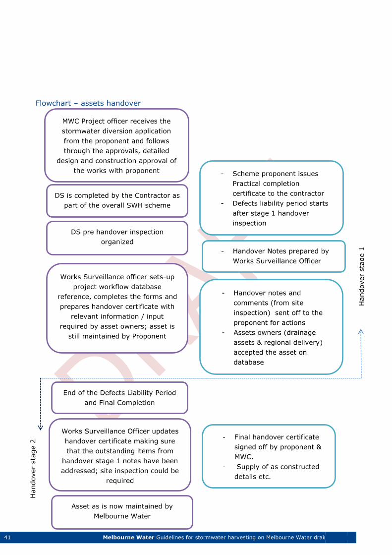
Flowchart – assets handover
DS is completed by the Contractor as
part of the overall SWH scheme
MWC Project officer receives the
stormwater diversion application
from the proponent and follows
through the approvals, detailed
design and construction approval of
the works with proponent
DS pre handover inspection
organized
Works Surveillance officer sets-up
project workflow database
reference, completes the forms and
prepares handover certificate with
relevant information / input
required by asset owners; asset is
still maintained by Proponent
- Handover notes and
comments (from site
inspection) sent off to the
proponent for actions
- Assets owners (drainage
assets & regional delivery)
accepted the asset on
database
- Scheme proponent issues
Practical completion
certificate to the contractor
- Defects liability period starts
after stage 1 handover
inspection
- Handover Notes prepared by
Works Surveillance Officer
Works Surveillance Officer updates
handover certificate making sure
that the outstanding items from
handover stage 1 notes have been
addressed; site inspection could be
required
End of the Defects Liability Period
and Final Completion
- Final handover certificate
signed off by proponent &
MWC.
- Supply of as constructed
details etc.
Asset as is now maintained by
Melbourne Water
Handover
sta
ge 2
Handover
sta
ge 1
42 Melbourne Water Guidelines for stormwater harvesting on Melbourne Water drainage assets
Special Melbourne Water requirements
Any works carried out on Melbourne Water “live “drainage assets must be carried out by
a Registered Contractor, subject to Melbourne Water registration requirements
Construction of the Works must conform to the design approved by Melbourne Water
Melbourne Water may require that Works be modified, removed or replaced at the
Owner's cost if they:
are not completed strictly in accordance with the final design
do not meet a construction standard acceptable to Melbourne Water
The construction of the Works must be carried out taking into account these guidelines,
relevant Melbourne Water Standard Drawings and Standard Specifications A Buildover
/Lease agreement is required for any constructions over Melbourne Water land or
easements. Refer to the Assets Services Team for a copy of the Buildover agreement.
The proposed diversion structure should be designed and constructed in a manner that
does not load the existing conduit
Melbourne Water must still have access to its assets at all times, including during
construction.
No services (e.g. electrical or plumbing) may be constructed within the Melbourne Water
drainage conduits
Any works to be conducted in the vicinity of existing drainage assets shall be undertaken
in a manner that protects the assets (i.e.: minimum vibration, loading, saw cut of pipe
instead of using a jack hammer, etc.).
Any damage caused to an asset due to the stormwater harvesting works shall be paid for
by the proponent/contractor
Before commencement of construction, the proponent may be required to undertake a
pre- and post- construction inspection of the existing assets to verify no damage has
been caused as a result of construction or existence of the stormwater structure.
When the construction is completed, “as constructed” drawings shall be supplied to
Melbourne Water for future record.
No contractors are allowed to enter Melbourne Water drainage assets unless prior
arrangement is made through the Drainage Area Co-ordinator or through the Diversion
Team by the application of a Permit to Work and a current Confined Space Entry ticket is
held.
It is the contractor’s responsibility that the location of the assets is proven on site before
any construction works commence.
Melbourne Water reserves the right to impose additional conditions upon the receipt of
design information from the proponent.
The contractor is required to submit a work method statement and tasks risk assessment
(TRA) to Melbourne Water’s Diversion Services team for approval prior to commencement of
construction.
43 Melbourne Water Guidelines for stormwater harvesting on Melbourne Water drainage assets
General
The stormwater harvesting diversion structure should be designed to have minimal
operational and maintenance requirements.
The requirement for regular personnel access into the underground structure to perform
maintenance activities should be avoided or minimised.
Use of mechanical equipment and moving parts should be avoided where practicable.
The operational and maintenance requirements for the diversion structure should be
included in an Operational & Maintenance Manual prepared for the stormwater harvesting
scheme with a copy provided to Melbourne Water for approval.
The recommended diversion structure options detailed on drawings 7251/10/001 -
7251/10/011 included in Appendix 2 to this report provide further detail on the
operational & maintenance requirements.
Minimum size of diversion pipeline
The minimum size of the pipeline from the diversion structure into the harvesting system
should be 375 mm nominal bore to minimise blockage risks.
Base/low flows and self-cleansing velocities allowance
For all new diversion structures installed on Melbourne Water drains, allowance should be
made for low/base flows to continue through the system prior/at the time of flow diversion
in order to avoid sediment deposition and associated maintenance problems in the drainage
network.
It is recommended that the minimum self-cleansing velocities for the design of these flows
are calculated on a case by case basis using the boundary shear stress approach as
described in these design guidelines. The design calculations shall prove that the design
solution allows for the continuation of base flows through the system and that these flows
produce the boundary bottom shear stress equal to or exceeding the pre-set minimal
boundary bottom shear stress of τ ≥ 1.5 Pa.
Refer to Appendix 1 for more detail on the boundary bottom shear stress calculations.
Section 5 - Operational & maintenance requirements
44 Melbourne Water Guidelines for stormwater harvesting on Melbourne Water drainage assets
Flow isolation devices
The design of diversion structures should allow for the temporary isolation of the harvesting
component from the diversion structure and associated drainage flows. This will allow for
maintenance activities on the scheme downstream of the harvesting structure and for
isolation in the case of emergency. To facilitate this, a sliding drop board arrangement
within the DS is recommended as detailed on drawing 7251/10/011 included in Appendix 2
of these guidelines.
For the temporary isolation of the entire diversion structure from the main drainage line
methods such as sandbagging and flow bypass or similar may be used on an as required
basis.
Maintenance frequency
The diversion structure should be designed with minimal requirements for maintenance.
The following maintenance frequency/procedures are typical:
Visual inspection (typically twice a year)
Cleaning by suction truck (as determined by inspection not more than once a year)
Maintenance access
The design should allow for adequate and safe access to the installed diversion structure for
maintenance and operation (e.g. cleaning).
This should include:
access road with turn-around circle for maintenance vehicles (e.g. suction track/crane)
providing sufficient reach to the installed structure
access for personnel entry/ inspection (min access shaft diameter 900 mm)
Only suitably qualified personnel with appropriate training and qualification/certification in
OHS and confined spaces entry procedures should be involved in the maintenance of the
diversion structures.
Entries into Melbourne Water assets are subject to Melbourne Water confined spaces entry
and permit to work systems. Permits must be arranged through the Drainage Area
Coordinators.
The recommended options for the diversion structures outlined in the standard drawings
forming part of these guidelines incorporate provisions for the routine maintenance (e.g.
open/close flow isolation device, cleaning with vacuum truck etc.) to be conducted from the
45 Melbourne Water Guidelines for stormwater harvesting on Melbourne Water drainage assets
ground level without the need to enter the DS. However safe access into the DS is still
required for any major maintenance, alterations and emergencies.
Adjustment and Calibration
The diversion structure design should have allowance for further adjustments and
calibration (e.g. base flow passage rates, diversion rates etc.) where practicable.
Exclusions and Clarifications
1. Melbourne Water at its discretion may accept reduced requirements for the low flow/self-
cleansing velocities in the Diversion Structure design if it can be demonstrated that
sufficient self-cleansing velocities are generated in the downstream section on the main
drainage line as a result of additional inflows into the drainage system from other
contributing drains in close proximity.
2. If the stormwater harvesting scheme (or part of) becomes decommissioned –the scheme
operator in consultation with Melbourne Water must perform the works deemed
necessary for the decommissioning or alteration of the diversions structure to ensure the
continued safe and reliable operation of the drainage assets. Such works to be performed
at the scheme operators cost.
46 Melbourne Water Guidelines for stormwater harvesting on Melbourne Water drainage assets
Licence requirement
The harvesting of water from Melbourne Water’s drains and waterways requires a licence
under Section 51 of the Water Act 1989.
Licences require a resource assessment to determine whether sufficient water is available to
satisfy the licence volume without impacting on existing users or the environment. The
licence proponent will be required to provide supporting evidence to Melbourne Water as
part of their application which demonstrate the catchment modelling and water availability
calculations undertaken in support of the harvesting scheme.
Base / dry weather flow in drains and waterways is not considered urban stormwater.
Urban stormwater is the increase in storm runoff resulting from an increase in
imperviousness of an urban catchment. Applications will need to demonstrate how they are
making allowance for passage of base flows in the drainage system.
The construction work on Melbourne Water Assets will require a Works Licence. All works
must be carried out to Melbourne Water standards. Works licences may contain a range of
conditions including requirements for the proponent to:
engage suitably qualified contractors
undertake recipient training for work on MWC assets
obtain necessary permits to work
hold appropriate confined space licences, etc.
pay appropriate fees and bonds
undertake asset handover processes.
To make application for both a stormwater licence and associated works licence Melbourne Water will require the following:
A stormwater application form completed in full and signed by the party who will hold the
licence. Application forms are available from Melbourne Water or on the website at
http://www.melbournewater.com.au/diverters
A cheque made out to Melbourne Water Corporation for the relevant application fees.
Hydrologic analysis and modelling of the proposal. The modelling should be undertaken
for the catchment upstream of the off take location and for the overall catchment and
should show current flows along with expected change in flow condition as a result of the
Section 6 - Licensing and Flow Meter requirements
47 Melbourne Water Guidelines for stormwater harvesting on Melbourne Water drainage assets
harvesting proposal. It should be undertaken showing an average and a dry year and be
conducted to a weekly (or more frequent) time scale.
Works Plans for proposed works including proposed operation and maintenance. These
should be properly engineered drawings detailing the works and include locality plan,
detail plans and suitable cross sections.
Copy of title(s) for the property where water will be used.
Irrigation and Drainage Plan detailing the irrigation requirements and scheduling of
application as well as drainage and runoff controls to be put in place on the site.
Details of existing or proposed storages.
Digital Photos of proposed pump / works locations.
Demonstrated evidence that the applicant has obtained permission or consent from the
owner of any land on which the works are, or will be, situated. Additional information on licensing can be obtained from MWC Diversion Management team
at 131 722.
Flow meters
Accurate measurement of water supplied and accounting for water use against a customer’s
entitlement is a focus of the Australian Government under the Australian
Standard AS 4747 “Meters for non-urban water supply”.
These standards sit alongside the metering provisions of the National Water Initiative
Agreement (NWI) which specifies the need to develop national standards for meter design
and installation for consistent measurement of usage. All state governments have signed
onto the National agreement.
All stormwater harvesting schemes proposed to be installed on Melbourne Water drainage
assets will require metering. It is a requirement of the diversion licence that an approved
flow meter be installed within the works in order to:
Provide an accurate record of volumes diverted
Monitor actual usage to ensure it falls within individual licensed allocated volumes
Provide water use data for Statewide reporting
Installation of the meter will be at the licensee’s cost and Melbourne Water shall not be
liable for any damage to customer infrastructure due to meter installation. Meters will be
supplied by Melbourne Water at the cost of the applicant and will remain the property of
Melbourne Water Corporation. All new meters are to be pattern approved according to
AS4747.
48 Melbourne Water Guidelines for stormwater harvesting on Melbourne Water drainage assets
There is a need to undertake an assessment of proposed works in order to gather certain
information before an informed choice can be made regarding the water meter to be
installed. The information relates to the type of diversion structure and associated
stormwater harvesting infrastructure proposed including size, type of pipe and general
pumping plant set-up. This assessment determines the most suitable type of meter for the
project as well as enabling the calculation of the likely range of flow rates to be metered
and discussion with the stormwater harvesting proponent on preferred location.
The proponent will need to make suitable allowance in the works design to provide for
meter installation and smooth flow leading into and out of the meter. This will mean
providing 10x the pipe diameter of straight pipe upstream of the meter and 5x the pipe
diameter downstream of the meter. There should be no valves, bends or other flow
interference in this space.
Certified Meter Validators
• Only Certified Meter Validators can undertake any works on Melbourne Water irrigation
meters.
• Training is available via Irrigation Australia (www.irrigation.org.au) or other accredited
training institutions.
Access to meters
In designing a stormwater scheme, proponents should also ensure adequate allowance has
been made for the required access to the meter for reading and maintenance purposes:
The meter installation site must be accessible to vehicles and machinery wherever
practical.
The meter should be installed above ground wherever possible and free from other
obstructions.
Safe access must be provided to meters (e.g. provision of covers, steps, platforms and
handrails etc.) and comply with the requirements of relevant Health and Safety Acts and
be in accordance with relevant Australian Standards.
All meter installations shall be configured and tested as soon as practicable upon completion
of each installation. It is a requirement that all meter installations undergo configuration
and testing to ensure that they meet the requirements of the specification.
49 Melbourne Water Guidelines for stormwater harvesting on Melbourne Water drainage assets
General
In summary of the major components in these guidelines the following set of design
parameters for diversion structures on Melbourne Water drainage assets has been
established:
The diversion structure should:
Collect the agreed volume of urban runoff from the contributing catchment(s); the
volume of water permitted for collection should be as per requirements of the diversion
license issued by Melbourne Water
Make allowance for low/base flows to continue through the system prior to and at the
time of flow diversion in order to avoid sediment deposition and associated maintenance
problems in the drainage network
Pass required base flows downstream to receiving waterways where they are providing
for ecological benefits prior to and at the time of flow diversion.
Not cause any adverse impact on the hydraulic capacity of the existing drainage system.
The hydraulic impact of the proposed installation should be checked, documented and
presented to Melbourne Water for approval prior to works commencement
Be designed to have minimal operational and maintenance requirements
Be designed to avoid or minimize the requirement for personnel access into the
underground structure
Avoid where practicable the use of mechanical equipment and moving parts
Include an Operational & Maintenance Manual prepared for the stormwater harvesting
scheme and the diversion structure, a copy of which should be provided to Melbourne
Water for approval
Have a minimum size of pipeline from the diversion structure into the harvesting system
of 375 mm nominal bore to minimize blockage risks
Have arrangements in place for the temporary isolation of the harvesting component
from the main diversion structure for maintenance
Make allowance for adequate and safe access to the installed diversion structure for
maintenance and operation purposes
Make allowance for further adjustments and calibration (e.g. base flow passage rates,
diversion rates etc.) where practicable
Section 7 - Recommended Design Options
50 Melbourne Water Guidelines for stormwater harvesting on Melbourne Water drainage assets
A number of preferred Diversion Structure design options have been developed that address
these requirements with three options selected for inclusion in this document as Melbourne
Water recommended options.
The three recommended options are further described in the following sections of this
document with engineering drawings contained as appendices in Appendix 2.
Option 1
Option 1 has been specifically developed for stormwater harvesting diversions where
limitations on the headloss/hydraulic impact are of particular importance and where there
are defined requirements for continuous base/environmental flows passage.
This option is based on a low/base flow channel and an overflow side weir arrangement. The
details of this option are provided on the drawings 7251/10/002, 7251/10/003 and
7251/10/004 included in Appendix 2.
The design rationale for this option is as follows:
The pre-determined base/maintenance flows pass through the DS via the low/base flow
channel unhindered; the volume / flow rate for these flows is determined by the size and
height of the channel
When the flow rate in the incoming conduit reaches the predetermined value - the
diversion into the stormwater harvesting component commences via the side weir while
the required low flows are still being passed through the DS into the receiving
environment
When the stormwater harvesting storages are full the water level in the DS rises to the
top of side weir and all the incoming flows are passed straight through the DS and into
the downstream drainage system
During large flow events – provided that the stormwater harvesting scheme can still
accept inflows – the DS should be able to provide both the harvesting of flows and
passage of the excess flow into the downstream drainage system functions
The grade of the base flows channel shall be the same as the gradient of the main drainage
system in order to provide the smooth transition of flows and have minimal hydraulic
impact.
The design of this DS specifies half pipe benching on the side opposite to the side overflow
to minimize the hydraulic disturbance/headloss during high flow operations.
The minimum drop of 600 mm from the main drainage pipe to the collection chamber invert
is recommended for this option based on the 375 ID diversion pipe into the stormwater
harvesting component.
51 Melbourne Water Guidelines for stormwater harvesting on Melbourne Water drainage assets
The DS incorporates an isolation device for the temporary isolation of the harvesting
component from the main diversion structure during scheduled maintenance. Specific
details on the recommended isolation arrangements can be found on drawing 7251/10/011
included in Appendix 2.
This option also allows for an access lid and shaft of 900mm x 900mm for ease of
maintenance and access.
The DS should be designed making allowance for the routine maintenance (e.g. open/close
flow isolation device, cleaning with vacuum truck etc.) to be conducted from ground level
without the need to enter the DS. However safe access into the DS is still required for major
maintenance, modifications and emergencies.
Note: Option 1 design can be used for diversion of flows under both sub-critical and super-
critical flow regimes in the main drainage systems with reliable operation under both
scenarios.
Option 2
Option 2 incorporates a low crest transverse weir (typ. 100 mm) and a small drop in the
invert of the diversion structure (100 mm typ.) that, in combination, create sufficient head
for the diversion of low harvestable flows from large drainage conduits with relatively flat
grades.
The details of this option are provided on the drawings 7251/10/005, 7251/10/006 and
7251/10/007 included in Appendix 2.
The small weir is designed to overflow frequently and therefore there are no separate
provisions for the self-cleansing / base flows passage in this option. Typically the low crest
weir is designed to create the min head required for the diversion of the harvestable flows
and it is therefore important that the designer minimises any backwater effects and/or
headlosses in the diversion pipeline in order to secure the diversion of the designed volume
for harvesting.
The weir should be positioned at a sufficient distance (min ½ pipe ID) from the
incoming/outgoing main drainage pipe and concrete benching provided to allow for the
smooth flow transition and minimisation of hydraulic losses within the DS.
The DS incorporates an isolation device for the temporary isolation of the harvesting
component from the main diversion structure during scheduled maintenance.
Option 2 also allows for an access lid and shaft of 900mm x 900mm for ease of
maintenance and access.
52 Melbourne Water Guidelines for stormwater harvesting on Melbourne Water drainage assets
The DS should be designed making allowance for routine maintenance (e.g. open/close flow
isolation device, cleaning with vacuum truck etc.) to be conducted from ground level
without the need to enter the DS. However safe access into the DS is still required for major
maintenance, modifications and emergencies.
Note: This option is best suited for the diversion of flows from large drainage pipes with
sub-critical flow regime. The use of this option for the diversion of flows on steep grade/high
velocity/super-critical flow drainage should be avoided.
Option 3 Option 3 combines a drop structure with a pre-screening grate as an entry point/inlet to the
diversion pipe.
The details of this option are provided on drawings 7251/10/008, 7251/10/009 and
7251/10/010 included in Appendix 2.
The design rationale for this option is as follows:
The pre-determined base/maintenance flows pass through the DS via the low/base flow
channel incorporated into the grate design. The volume / flow rate for these flows is
determined by the height of the channel. Also please note the need for benching to direct
the base flows into the channel
When the flow rate in the incoming conduit reaches the predetermined value (exceeds
the flow capacity of the low flow channel) - the diversion into the stormwater harvesting
component commences (via the side weirs/sides of the base channel and grate) while the
required low flows are still being passed through the DS into the receiving environment
When the stormwater harvesting storages are full the water level in the DS rises to the
underside of the grate and all the incoming flows are passed straight through the DS and
into the downstream drainage system
During large flow events – provided that the stormwater harvesting scheme can still
accept inflows – the DS should be able to provide both the harvesting of flows and
passage of the excess flow into the downstream drainage system functions
The grate in Option 3 comprises of 32 NB pipes with min 25 mm gap contained in the rigid
frame. The frame should be hinged for the ease of opening during maintenance operation.
Allowance should be made for the hinged section of the grate to be opened from the ground
level with the use of a handle/hook arrangement as detailed on drawing 7251/10/011
included in Appendix 2.
The grate should be positioned such that the 32 NB pipes are parallel to the main drainage
flow in order to minimize potential for grate blockage.
53 Melbourne Water Guidelines for stormwater harvesting on Melbourne Water drainage assets
The grate and frame should be designed with adequate structural strength to allow for the
dead and live loads associated with the maintenance personnel access during maintenance.
The provisions for base flow passage within the diversion structure are incorporated into the
grate design (Enviro – channel profile).
The minimum drop of 600 mm from the main drainage pipe to the collection chamber invert
is recommended for this option based on the 375 ID diversion pipe into the stormwater
harvesting component.
The DS incorporates an isolation device for the temporary isolation of the harvesting
component from the main diversion structure during scheduled maintenance.
Option 3 design also incorporates an access lid and shaft of 900mm x 900mm for the ease
of maintenance and access.
The DS should be designed making allowance for the routine maintenance (e.g. open/close
flow isolation device, open/close the grate, cleaning with vacuum truck etc.) to be
conducted from ground level without the need to enter the DS. However safe access into
the DS is still required for major maintenance, modifications and emergencies.
Note: Option 3 has been specifically developed for flow diversions on large drainage
conduits including box culverts where large objects could be present in the incoming run off.
The function of the grating in this option is to provide the pre-screening barrier to these
large objects that could otherwise cause blockage of the diversion pipeline.
The effective area of the grating should be designed to cater for the secure passage of the
design flows for the diversion/harvesting under the reduced area/“partially blocked”
scenario (typically 50% blockage of the grate effective area).
Alternative Designs
While the options and designs above represent Melbourne Water’s preferred outcomes,
alternative or variations to these designs will be considered where they can demonstrate
that they meet the design objectives outlined in these guidelines.
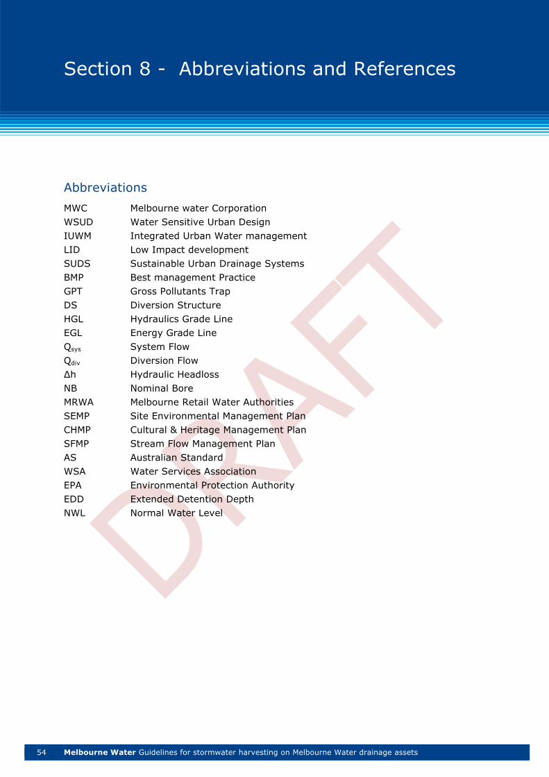
54 Melbourne Water Guidelines for stormwater harvesting on Melbourne Water drainage assets
Abbreviations
MWC Melbourne water Corporation
WSUD Water Sensitive Urban Design
IUWM Integrated Urban Water management
LID Low Impact development
SUDS Sustainable Urban Drainage Systems
BMP Best management Practice
GPT Gross Pollutants Trap
DS Diversion Structure
HGL Hydraulics Grade Line
EGL Energy Grade Line
Qsys System Flow
Qdiv Diversion Flow
Δh Hydraulic Headloss
NB Nominal Bore
MRWA Melbourne Retail Water Authorities
SEMP Site Environmental Management Plan
CHMP Cultural & Heritage Management Plan
SFMP Stream Flow Management Plan
AS Australian Standard
WSA Water Services Association
EPA Environmental Protection Authority
EDD Extended Detention Depth
NWL Normal Water Level
Section 8 - Abbreviations and References
55 Melbourne Water Guidelines for stormwater harvesting on Melbourne Water drainage assets
References
Water Sensitive Urban Design: Basic Procedures for ‘Source Control’ of Stormwater - A
Handbook for Australian Practice, Argue, J. R. (ed), Allen, M. D., Argue, J. R., Geiger, W. F., Johnston, L. D., Pezzaniti, D. and Scott, P. 2004, Urban Water Resources Centre,
University of South Australia, Adelaide, South Australia
Hydraulics in Civil and Environmental Engineering, Chadwick and Morfett, third edition,
1998
Understanding Hydraulics, L. Hamill, MACMILLAN 1995
Wastewater Hydraulics, Willi J. Hager, Springer 1999
Queensland Urban Drainage Manual second edition, 2007
Algorithms for pit pressure changes and hydraulic losses in stormwater drainage systems,
Geoffrey O’Loughlin & Bob Stack, conference paper abstract, 2007
Water Control Structures – Design for Natural Resources management on coastal floodplains, Ben Rampano, NSW Department of Industry & Investment, 2009
Environmental & Economic Assessment of Urban Water Services for a Greenfield
development, A. Sharma, A. Grant, T. Grant, F. Pamminger, L. Opray, Environmental
Engineering Science magazine, vol. 26, No 5 – 2009
Analysis of Climate Change Impact on the deterioration of concrete infrastructure, CSIRO National Research Flagship – 2010
Hydraulic design of Bosspipe lines, Water&Farr, 2005
Hydraulics Considerations for corrugated PE pipe, CPPA Association,2000
Sewerage Code WSA 02-2002-2.3 July 2004
Melbourne Water Access Covers, Platforms and Walkways Standard CORP AM S020 version 2, August 2014
Melbourne Water Handrail Standard CORP AM S021 version 1, August 2013
The Victorian Occupational Health and Safety Act 2004 – Section 28 “Duties of Designers of
buildings & structures”
Burns, M.J., Fletcher, T.D., and Edwards, C. (2015). Low-flow hydrology in the Melbourne
Water management region. April-2015. Melbourne Waterway Research-Practice Partnership
Technical Report 15.1.
56 Melbourne Water Guidelines for stormwater harvesting on Melbourne Water drainage assets
Poff, N. L., J. D. Allan, M. B. Bain, J. R. Karr, K. L. Prestegaard, B. D. Richter, R. E. Sparks
and J. C. Stromberg (1997). "The natural flow regime: a paradigm for river conservation and
restoration." BioScience 47: 769-784.
Walsh, C. J., A. H. Roy, J. W. Feminella, P. D. Cottingham, P. M. Groffman and R. P. Morgan (2005). "The urban stream syndrome: current knowledge and the search for a cure." Journal
of the North American Benthological Society 24(3): 706-723.
Walsh, C. J., T. D. Fletcher and M. J. Burns (2012). "Urban stormwater runoff: a new class of
environmental flow problem." PLoS ONE 7(9).
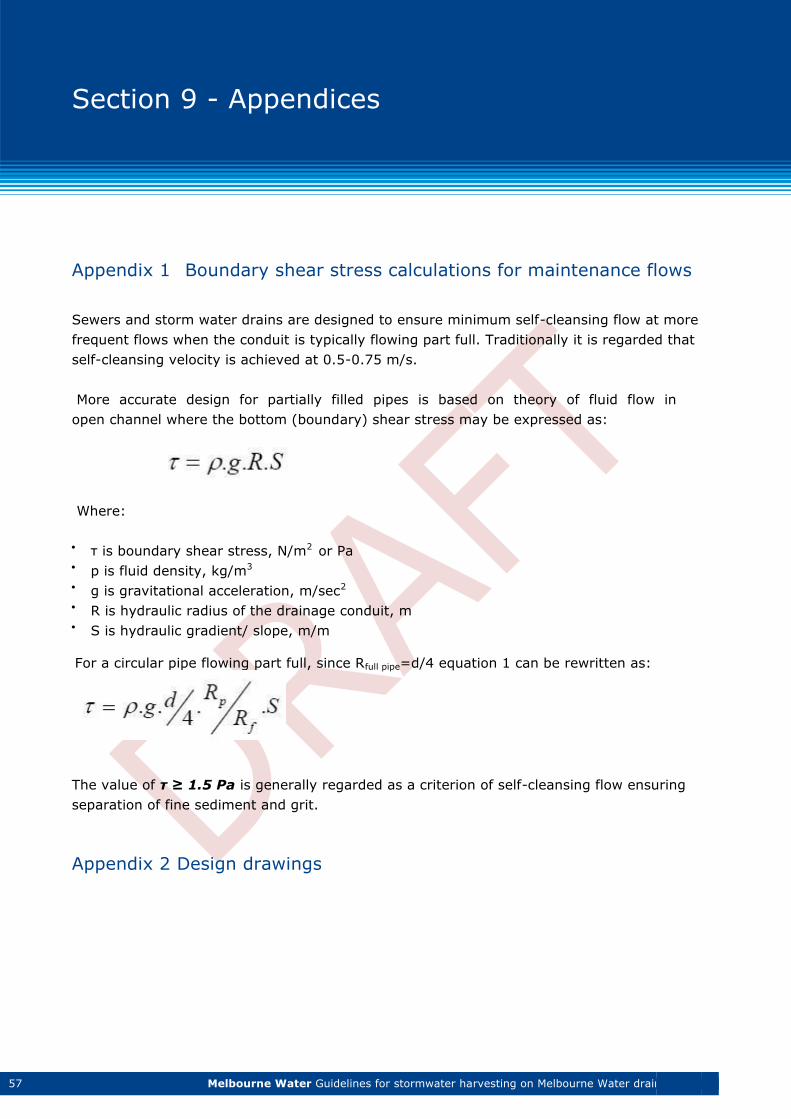
57 Melbourne Water Guidelines for stormwater harvesting on Melbourne Water drainage assets
Appendix 1 Boundary shear stress calculations for maintenance flows
Sewers and storm water drains are designed to ensure minimum self-cleansing flow at more
frequent flows when the conduit is typically flowing part full. Traditionally it is regarded that
self-cleansing velocity is achieved at 0.5-0.75 m/s.
More accurate design for partially filled pipes is based on theory of fluid flow in
open channel where the bottom (boundary) shear stress may be expressed as:
Where:
τ is boundary shear stress, N/m2 or Pa
p is fluid density, kg/m3
g is gravitational acceleration, m/sec2
R is hydraulic radius of the drainage conduit, m
S is hydraulic gradient/ slope, m/m
For a circular pipe flowing part full, since Rfull pipe=d/4 equation 1 can be rewritten as:
The value of τ ≥ 1.5 Pa is generally regarded as a criterion of self-cleansing flow ensuring
separation of fine sediment and grit.
Appendix 2 Design drawings
Section 9 - Appendices


1 Melbourne Water Guidelines for stormwater harvesting on Melbourne Water drainage assets
Melbourne Water
990 Latrobe Street, Docklands VIC 3008
PO Box 4342 Melbourne Victoria 3001
Telephone 131 722 Facsimile 03 9679 7099
melbournewater.com.au
ISBN 978-1-921911-22-4 (Print)
ISBN 978-1-921911-23-1 (Web)
© Copyright August 2015
Melbourne Water Corporation. All rights reserved.
No part of the document may be reproduced, stored in a retrieval system, photocopied or
otherwise dealt with without prior written permission of Melbourne Water Corporation.
Disclaimer: This publication may be of assistance to you but Melbourne Water and its
employees do not guarantee that the publication is without flaw of any kind or is wholly
appropriate for your particular purposes and therefore disclaims all liability for any error,
loss or other consequence which may arise from you relying on any information in this
publication.