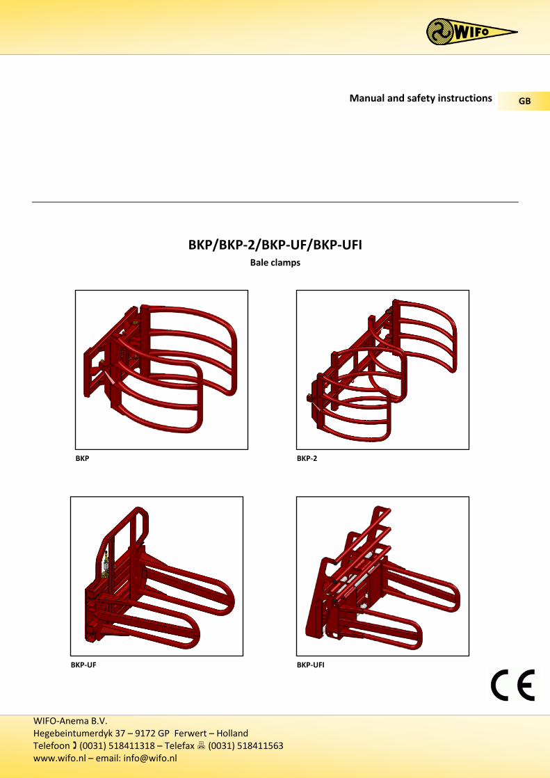
bkp/bkp-2/bkp-uf/bkp-ufi - wifo.nl...this bale clamp is intended for the transport of film-wrapped...
TRANSCRIPT
WIFO-Anema B.V. Hegebeintumerdyk 37 – 9172 GP Ferwert – Holland Telefoon (0031) 518411318 – Telefax (0031) 518411563 www.wifo.nl – email: [email protected]
Manual and safety instructions
BKP/BKP-2/BKP-UF/BKP-UFI Bale clamps
GB
BKP BKP-2
BKP-UF BKP-UFI

1
English
Table of contents
1. TO THE USER ...................................................................................................................................................................... 2
1.1 INTRODUCTION ...................................................................................................................................................................... 21.2 SAFETY PRECAUTIONS AND WARNINGS ........................................................................................................................................ 3
1.2.1 Safety regulations ..................................................................................................................................................... 31.2.2 Safety stickers and warning signs ............................................................................................................................. 51.2.3 Location of safety stickers on the machine .............................................................................................................. 5
1.3 PURPOSE OF USE .................................................................................................................................................................... 61.3.1 Instructions for picking up a round bale ................................................................................................................... 71.3.2 Instructions for picking up a rectangular bale .......................................................................................................... 7
1.4 LIABILITY ............................................................................................................................................................................... 81.5 WARRANTY ........................................................................................................................................................................... 8
2. TECHNICAL DETAILS ........................................................................................................................................................... 9
2.1 GENERAL TECHNICAL DATA ...................................................................................................................................................... 92.2 BKP .................................................................................................................................................................................. 10
2.2.1 Parts list .................................................................................................................................................................. 102.3 BKP + K-90 (ACCESSORY) ..................................................................................................................................................... 11
2.3.1 Parts list .................................................................................................................................................................. 112.4 BKP + D-180 (ACCESSORY) .................................................................................................................................................. 12
2.4.1 Parts list .................................................................................................................................................................. 122.5 BKP-2 ............................................................................................................................................................................... 13
2.5.1 Parts list .................................................................................................................................................................. 132.5.2 Commissioning the BKP/BKP + D-180/BKP-2 bale clamps ..................................................................................... 142.5.3 Commissioning the BKP + K-90 bale clamp ............................................................................................................ 14
2.6 BKP-UF ............................................................................................................................................................................. 152.6.1 Parts list .................................................................................................................................................................. 15
2.7 BKP-UFI ............................................................................................................................................................................ 162.7.1 Parts list .................................................................................................................................................................. 162.7.2 Commissioning the BKP-UF/BKP-UFI bale clamps ................................................................................................. 17
2.8 REPLACEMENT COMPONENTS .................................................................................................................................................. 18
3. FAULTS AND MAINTENANCE ........................................................................................................................................... 19
3.1 PREVENTIVE MAINTENANCE AND LUBRICATION .......................................................................................................................... 193.2 TROUBLESHOOTING .............................................................................................................................................................. 203.3 WORK TO BE CARRIED OUT BY A COMPETENT MECHANIC .............................................................................................................. 21
3.3.1 Replacement instructions, BKP + D-180 sliding bearing ......................................................................................... 21

2
1. To the user
1.1 Introduction
The aim of this manual is to inform users about the commissioning, use and maintenance of their new WIFO hydraulic bale clamp. Also included in this manual are a number of safety instructions to create a safe working environment.
At WIFO-Anema B.V. we aim to continuously improve our products. WIFO-Anema B.V. reserve the right to introduce any changes and improvements deemed necessary without prior notice.
Please read the manual thoroughly and observe the safety procedures before putting the unit into operation. Contact your dealer for any further questions or concerns you may have.
We hope you will enjoy working with your WIFO bale clamp.
Keep this manual in a safe place for future reference!
WIFO-Anema B.V.
Dealer:
ATTENTION: Carefully read this manual before you put the machine into operation and act upon all directions that are given. This is to guarantee its safe, trouble-free operation.
3
1.2 Safety precautions and warnings
Please read this manual before you put the machine into operation for the first time, and observe the safety instructions at all times. The most important instructions are marked with a symbol.
Any person in charge of the commencement of operation, the operation itself or the maintenance of the machine is urged to carefully read and observe the following instructions.
1.2.1 Safety regulations The following safety instructions apply to all types of WIFO bale clamp. It is not necessary to make any distinction here between the lifting vehicle used, or whether the bales are round or rectangular.
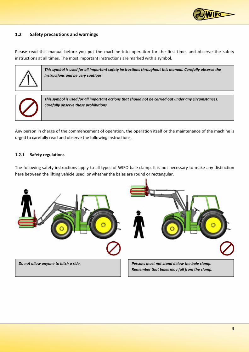
This symbol is used for all important actions that should not be carried out under any circumstances. Carefully observe these prohibitions.
Do not allow anyone to hitch a ride.
This symbol is used for all important safety instructions throughout this manual. Carefully observe the instructions and be very cautious.
Persons must not stand below the bale clamp. Remember that bales may fall from the clamp.

4
Bales should be transported in the lowest possible position, to provide maximum stability to the lifting vehicle.
The bale clamp must be placed in the lowest position when parking the lifting vehicle. Ensure that the clamp/vehicle combination cannot make any unintended movements while the vehicle is not in use. Disconnect the hydraulic hoses if necessary. When the bale clamp is removed from the lifting vehicle and parked it should be placed on a level and stable substrate.
Ensure that the hydraulic hoses and any electrical cables cannot be trapped, and that the grabs are able to move freely.
Ensure that the cylinder control lever cannot be confused with other controls, in order to prevent unintended operation.
The clamp must only be operated from the driver's position in the lifting vehicle. Make sure the operator has full view of the work to be carried out.

5
2 1 2 1
1.2.2 Safety stickers and warning signs
Several safety stickers have been put onto the machine. The meaning of the stickers on this machine is as follows:
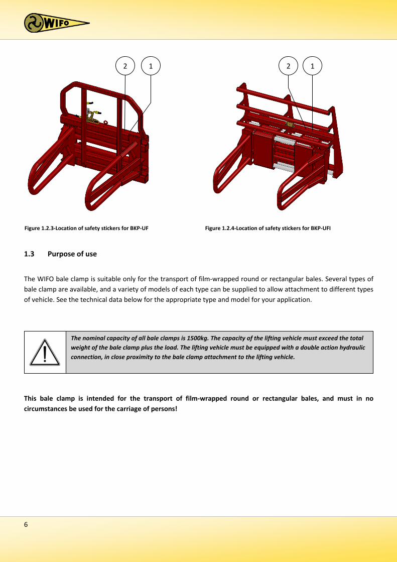
1.2.3 Location of safety stickers on the machine
A safe working environment also requires personnel to be well-informed about the various safety stickers on the machine. Be aware of the hazards they warn you to look out for.
Replace any loose, illegible or missing stickers.
Figure 1.2.1-Location of safety stickers for BKP Figure 1.2.2-Location of safety stickers for BKP-2
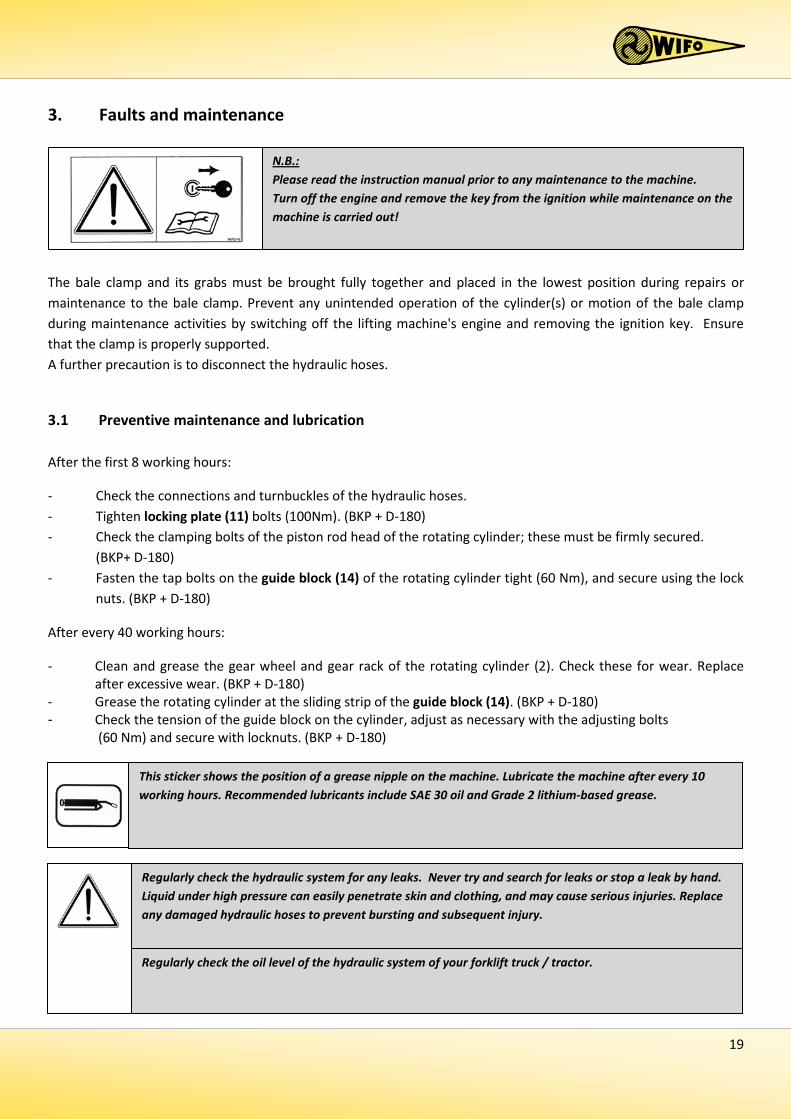
N.B.: Please read the instruction manual prior to any maintenance to the machine. Turn off the engine and remove the key from the ignition while maintenance is carried out on the machine!
1
Danger: Always keep at a safe distance from the machine!
2
6
1.3 Purpose of use
The WIFO bale clamp is suitable only for the transport of film-wrapped round or rectangular bales. Several types of bale clamp are available, and a variety of models of each type can be supplied to allow attachment to different types of vehicle. See the technical data below for the appropriate type and model for your application.
This bale clamp is intended for the transport of film-wrapped round or rectangular bales, and must in no circumstances be used for the carriage of persons!
Figure 1.2.3-Location of safety stickers for BKP-UF Figure 1.2.4-Location of safety stickers for BKP-UFI
2 1 1 2
The nominal capacity of all bale clamps is 1500kg. The capacity of the lifting vehicle must exceed the total weight of the bale clamp plus the load. The lifting vehicle must be equipped with a double action hydraulic connection, in close proximity to the bale clamp attachment to the lifting vehicle.
7
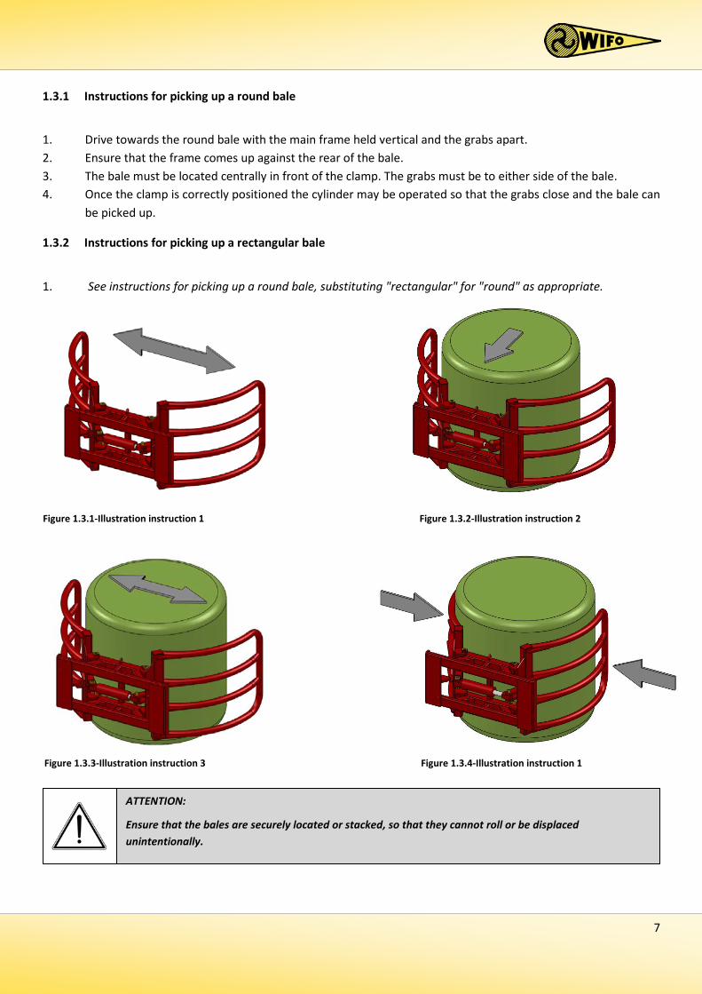
1.3.1 Instructions for picking up a round bale
1. Drive towards the round bale with the main frame held vertical and the grabs apart. 2. Ensure that the frame comes up against the rear of the bale. 3. The bale must be located centrally in front of the clamp. The grabs must be to either side of the bale. 4. Once the clamp is correctly positioned the cylinder may be operated so that the grabs close and the bale can
be picked up.
1.3.2 Instructions for picking up a rectangular bale
1. See instructions for picking up a round bale, substituting "rectangular" for "round" as appropriate.
Figure 1.3.1-Illustration instruction 1 Figure 1.3.2-Illustration instruction 2
Figure 1.3.3-Illustration instruction 3 Figure 1.3.4-Illustration instruction 1
ATTENTION:
Ensure that the bales are securely located or stacked, so that they cannot roll or be displaced unintentionally.
8
1.4 Liability
Any person working with or on the machine must have read this manual. The machine is to be used for its intended purpose only. Included in the intended purpose are, among other things:
1. Work must be carried out in accordance with the directions and within the functional restrictions (e.g. maximum hydraulic working pressure) as outlined in the regulations. Use only sound and appropriate tools.
2. Electric/electronic equipment and accessories (e.g. cables) must be treated in accordance with the general accepted policy for using non-waterproof portable electric and electronic equipment, such as:
a) Storing and keeping in a clean, dry environment away from rodents and the like; and b) Protecting the equipment against severe, uncushioned shocks and water (precipitation).
3. Use only original or compatible spare parts. Such parts must be assembled as directed (e.g. by observing the
recommended tightening moments). Spare parts (as well as lubricants) are considered compatible only if explicitly approved by WIFO or in the event that the customer is able to prove they possess the required properties for the purpose(s) they are used.
4. Use only lubricants that meet the specifications as described in the directions. 5. Always observe the local regulations in terms of accident prevention, safety, traffic and transport. 6. Only trained personnel with knowledge of the possible hazards have permission to work with/on the
machine. 7. WIFO-Anema B.V. will assume no liability in any shape or form for losses or damage caused following
modifications to the machine, which have not been explicitly approved by WIFO.
y
1.5 Warranty
WIFO-Anema B.V. guarantees the soundness of its products in terms of materials used and/or structural defects. However, in any event this warranty is limited to the free-of-charge replacement or repairs of the defect product, or part thereof. WIFO-Anema B.V. assumes no liability for any loss or damage arising from faulty deliveries and/or the breakdown of purchased goods before the warranty period has expired. The warranty period for this product is twelve months.
Noncompliance with the rules and directions from this manual will be considered as serious negligence, for the consequences of which WIFO-Anema B.V. accepts no liability whatsoever. In such cases, the user will bear the full risk of his actions.
WIFO-Anema B.V. is continuously working on the improvement of its products. For that reason, WIFO-Anema B.V. reserves the right to introduce any changes and improvements deemed necessary without prior notice. However, it does not imply an obligation to make any such changes or improvements to machines bought by customers in the past.

9
2. Technical details
2.1 General technical data
1 Weighting excluding add-on components
Type Description Rotating angle K-90 Vertical swinging frame for use with lifting mast etc. 90° D-180 Horizontal rotary gear for use with front loader etc. 180°
A variety of accessories for fitting on the lifting vehicle are available for each type of bale clamp. This depends on the type of vehicle in use with the WIFO bale clamp.
Type BKP BKP-2 BKP-UF BKP-UFI Max. carrying capacity 1500 kg 2 x 1250 kg 1500 kg 1500 kg Weight1 250 kg 370 kg 325 kg 600 kg Max. working pressure 18Mpa (180bar) 18Mpa (180bar) 14Mpa (140bar) 14Mpa (140bar) Frontal extension length 250 mm 100 mm 170 mm 340 mm Clamp capacity 900 – 1300 mm 900 – 1300 mm 750 – 2050 mm 720 – 2480 mm Min. machine width 1140 mm 2550 mm 1150 mm 1500 mm Bale type Round Round Round/Rectangular Round/Rectangular
Table 2.1.1-Wifo bale clamp models
Type Letter Description BKP/BKP-2/BKP-UF/BKP-UFI K Bare frame for build-up by user H WIFO lifting mast linkage D Three point (cat.II) linkage V Front loader linkage
Table 2.1.2-Description data on model plate
Table 2.1.3-WIFO BKP bale clamp accessories

10
2.2 BKP
2.2.1 Parts list
Number Description 1 BKP main frame 2 BKP clamp 3 BKP clamp cylinder DW 80-40-200 4 Cylinder pin 5 Hinge pin 6 Support leg pin 7 Support leg
Table 2.2.1-BKP parts list

11
2.3 BKP + K-90 (accessory)
The BKP bale clamp can be fitted with a swinging frame between the bale clamp and the lifting mast fork carrier, in order to rotate round bales through 90°. An additional double action hydraulic connection at the lifting mast fork carrier is required for this operation.
2.3.1 Parts list
Number Description Number Description 1 BKP main frame 9 Tilting cylinder plate 2 BKP clamp 10 Clamp plate tipping cylinder plate 3 BKP clamp cylinder DW 80-40-200 11 Rotating point plate 4 Cylinder pin 12 Tilting cilinder DW 70-40-410 5 Hinge pin 13 Bearing 6 Support leg pin 14 Bottom cylinder pin 7 Support leg 15 Rod side cylinder pin 8 Fixed frame 16 Tilting pin
Table 2.3.1-Parts list for BKP + K-90

12
2.4 BKP + D-180 (accessory)
The BKP bale clamp can be equipped with a rotary frame, allowing the bale clamp to rotate through 180°. An additional double action hydraulic connection is required on the lifting vehicle for this operation.
2.4.1 Parts list
Number Description Number Description 1 Rotary frame 9 Sleeve bearing 2 BKP clamp 10 Bronze washer 3 BKP clamp cylinder 11 Locking plate 4 Cylinder pin 12 Tilting cylinder DW 70-30-377 5 Hinge pin 13 Guide block holder 6 Support leg pin 14 Guide block 7 Support leg 15 Locking pin 8 Fixed frame
Table 2.4.1-Parts list for BKP + D-180
13
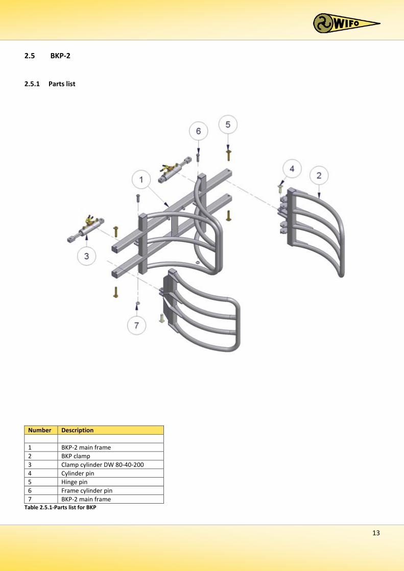
2.5 BKP-2
2.5.1 Parts list
Table 2.5.1-Parts list for BKP
Number Description 1 BKP-2 main frame 2 BKP clamp 3 Clamp cylinder DW 80-40-200 4 Cylinder pin 5 Hinge pin 6 Frame cylinder pin 7 BKP-2 main frame
14
2.5.2 Commissioning the BKP/BKP + D-180/BKP-2 bale clamps 1. The method of attaching the film-wrapped round bale clamp depends on the format of the clamp.
Descriptions of the methods for the different formats are provided below:
a) Three point (cat. II) linkage Check that the drawbars of the power lift of the tractor are at the same level. Couple the clamp to the category II three point linkage. Use the appropriate pins and retaining clips. Adjust the top link so that the bale clamp is horizontal. Only very little lateral play of the bale clamp in the power lift is allowed. Make the adjustments via the stabilizers of the power lift.
b) Front loader, reach truck and shovel linkage Unlock the quick attachment frame. Tilt the frame forward using the tilting cylinders. Hook the bale clamp onto the front loader, reach truck or shovel. The hooks must engage between the quick attachment system guide strips. Now tilt the frame to the rear using the tilting cylinders and lock the quick attachment frame so that the clamp is firmly attached.
c) Lifting mast Remove the pins. Hook the bale clamp onto the lifting mast so that the clamp sits centrally behind the mast. Replace the pins so that the clamp is firmly attached. Use appropriate pins, nuts and bolts.
2. Connect the hydraulic hoses and ensure that the quick connectors are clean so that no contamination is
introduced to the machine's hydraulic system. 3. Subsequently check that the hydraulic hoses can move freely and check that the system is not leaking oil. 4. Check the operation of the bale clamp using the hydraulic controls.
2.5.3 Commissioning the BKP + K-90 bale clamp
1. The BKP type bale clamp is suitable for use with a lifting mast and can be equipped with a swinging frame between the bale clamp and the lifting mast fork carrier to allow round bales to be rotated through 90°. An additional double action hydraulic connection at the lifting mast fork carrier is required for this operation. Instructions for connection to a lifting mast are provided below:
a) Lifting mast
Remove the pins. Hook the swinging frame onto the lifting mast so that the frame sits centrally behind the mast. Replace the pins, so that the swinging frame is firmly secured to the lifting mast. Then attach the bale clamp to the swinging frame. Use appropriate pins, nuts and bolts.
The WIFO bale clamp is now ready for use.

15
2.6 BKP-UF
2.6.1 Parts list
Number Description 1 BKP-UF main frame 2 Clamping cylinder DW 60-35-665 3 BKP-UF clamp 4 BKP-UF pin 5 BKP-UF locking plate
Table 2.6.1-Parts list for BKP-UF

16
2.7 BKP-UFI
2.7.1 Parts list
Where the lifting vehicle is not equipped with two double action connections, an electro/hydraulic switching valve or two 3-way valves can be used to operate the width setting cylinders.
Number Description 1 BKP-UFI main frame 2 Bearing section 3 BKP-UFI clamp 4 Main frame guide shaft 5 Main frame guide shaft locking plate 6 Clamp arm guide shaft 7 Clamping cylinder DW 60-35-550 8 Adjusting cylinder DW 50-30-330 9 Guide strip 10 Plastic bushes 11 Electro/hydraulic switching valve
Table 2.7.1-Parts list for BKP-UFI
17
2.7.2 Commissioning the BKP-UF/BKP-UFI bale clamps 1. The method of attaching the film-wrapped rectangular bale clamp depends on the format of the clamp.
Descriptions of the methods for the different formats are provided below: a) Three point (cat. II) linkage
Check that the drawbars of the power lift of the tractor are at the same level. Couple the clamp to the category II three point linkage. Use the appropriate pins and retaining clips. Adjust the top link so that the bale clamp is horizontal. Only a very small amount of lateral play of the bale clamp in the power lift is permissible. Make the adjustments via the stabilizers of the power lift.
b) Front loader, reach truck and shovel linkage Unlock the quick attachment frame. Tilt the frame forward using the tilting cylinders. Hook the bale clamp onto the front loader, reach truck or shovel. The hooks must engage between the quick attachment system guide strips. Now tilt the frame to the rear using the tilting cylinders and lock the quick attachment frame so that the clamp is firmly attached.
c) Lifting mast Remove the pins. Hook the bale clamp onto the lifting mast so that the clamp sits centrally behind the mast. Replace the pins so that the clamp is firmly attached.
2. Connect the hydraulic hoses, ensuring that the quick connectors are clean to prevent contamination entering
the machine's hydraulic system. Where the lifting vehicle is not equipped with two double action connections, an electrically operated switching valve or two 3-way valves can be used to operate the width setting cylinders. The following hydraulic hoses may be connected, depending on the format of the clamp:
a) Two-four hose connection
Connect the two pairs of hydraulic supply/offtake hoses to the two double action connections on the fork carrier.
b) Electrically operated switching valve Connect the hydraulic supply/discharge hoses to the dual-action connection on the fork carrier. Install the supplied switch so that the machine driver is able to operate it from his driving position and cannot confuse it with other controls. For a safe working environment, avoid situations such as inadvertently starting the machine or not being able to control it. Keep an eye on the correct voltage of the lifting device and the valve. The voltage is shown on the coil. Connect a twin core cable in accordance with the circuit diagram. Include a warning light, fuse and/or plug socket in the circuit if required.
3. Check that the hydraulic hoses and electrical cables are able to move freely throughout, and check the
system for oil leaks. 4. Check the operation of the bale clamp using the hydraulic controls.
The WIFO bale clamp is now ready for use.

18
2.8 Replacement components
Type Accessories Component number BKP Clamping cylinder supply and offtake hoses HYLR180031WW90
Overpressure/non-return valve 419058 Clamping cylinder seal kit 779288 BKP + K-90 Clamping cylinder supply and offtake hoses HYLR180031WW90 Supply/discharge hoses to rotating cylinder HYLR100031WW90 Overpressure/non-return valve 419058 Clamping cylinder seal kit 779288 Rotating cylinder seal kit 7792862 BKP + D-180 Clamping cylinder supply/offtake hose HYLR180031WW90 Rotating cylinder supply/offtake hose HYLR130031WW90 Hose HYLR040031WW90 Electro/hydraulic switching valve 429052 Overpressure/non-return valve 419058 Clamping cylinder seal kit 779288 Rotating cylinder seal set 779187A Single-acting balancing valve 4290057 Sleeve bearing 429027 BKP-2 Clamping cylinder supply and offtake hoses HYLR250031WW90
Volume control valve HYVENTREGEL Electro/hydraulic switching valve 429052 Overpressure/non-return valve 419058 Clamping cylinder seal set 779288 BKP-UF Supply hose HYLR180031WW90
Offtake hose HYLR180041GG90 Hose HYLR042031WW Hose HYLR073531WW Hose HYLR100031WW90 Hose HYLR080031WW90 1/2" pressure relief valve, 100-180 bar 419056 Single action controlled 3/8" non-return valve 419055 Clamping cylinder seal set 779284 BKP-UFI Offtake hose HYLR180041GG90 Supply hose HYLR180031WW90 Hose HYLR060031WW90 Hose HYLR080031WW Hose HYLR080031WW90 Hose HYLR100031WW90 Clamping cylinder seal kit 779283 Adjusting cylinder seal kit 779283 Plastic bushes 419038 Overpressure/non-return valve ½” 419058
Table 2.8.1-Replacement components for WIFO bale clamps
19
3. Faults and maintenance
The bale clamp and its grabs must be brought fully together and placed in the lowest position during repairs or maintenance to the bale clamp. Prevent any unintended operation of the cylinder(s) or motion of the bale clamp during maintenance activities by switching off the lifting machine's engine and removing the ignition key. Ensure that the clamp is properly supported. A further precaution is to disconnect the hydraulic hoses.
3.1 Preventive maintenance and lubrication After the first 8 working hours:
- Check the connections and turnbuckles of the hydraulic hoses. - Tighten locking plate (11) bolts (100Nm). (BKP + D-180) - Check the clamping bolts of the piston rod head of the rotating cylinder; these must be firmly secured.
(BKP+ D-180) - Fasten the tap bolts on the guide block (14) of the rotating cylinder tight (60 Nm), and secure using the lock
nuts. (BKP + D-180)
After every 40 working hours:
- Clean and grease the gear wheel and gear rack of the rotating cylinder (2). Check these for wear. Replace after excessive wear. (BKP + D-180)
- Grease the rotating cylinder at the sliding strip of the guide block (14). (BKP + D-180) - Check the tension of the guide block on the cylinder, adjust as necessary with the adjusting bolts
(60 Nm) and secure with locknuts. (BKP + D-180)
Regularly check the hydraulic system for any leaks. Never try and search for leaks or stop a leak by hand. Liquid under high pressure can easily penetrate skin and clothing, and may cause serious injuries. Replace any damaged hydraulic hoses to prevent bursting and subsequent injury.
Regularly check the oil level of the hydraulic system of your forklift truck / tractor.
N.B.: Please read the instruction manual prior to any maintenance to the machine. Turn off the engine and remove the key from the ignition while maintenance on the machine is carried out!
This sticker shows the position of a grease nipple on the machine. Lubricate the machine after every 10 working hours. Recommended lubricants include SAE 30 oil and Grade 2 lithium-based grease.

20
3.2 Troubleshooting
Bale clamp type Problem Solution BKP + D-180. The bale clamp is not in its horizontal position
when the cylinder piston rod is fully slid in. Loosen the clamping bolts at the ends of the piston rod and screw/unscrew the piston into or out of the block. Continue with this until the rotary frame (1) is horizontal with reference to the fixed frame (8). Tightly secure the clamping bolts.
There is some play in the bearing (sleeve bearing) on the shaft of the fork positioner.
The bearing is worn-out and must be replaced by a skilled mechanic. See chapter 3.3.1.
Table 3.2.1-Troubleshooting
Please contact your dealer for any further concerns you may have. He will be pleased to assist.

21
3.3 Work to be carried out by a competent mechanic
3.3.1 Replacement instructions, BKP + D-180 sliding bearing
1. Disconnect the hydraulic hoses. 2. Remove the bale clamp from the lifting vehicle and place it on its back on a level and stable substrate. 3. Take the pressure off the guide block (14) by loosening the pressure bolts. 4. Support the bale clamp so that it no longer rests on the rotary frame (1) gear wheel.
(Use suitable lifting equipment. The minimal lifting capacity must exceed the weight of the bale clamp, see the technical data in Section 2.1)
5. Remove the locking plate (11) after unscrewing the six socket bolts. Prevent the rotary frame slipping off the backing plate.
6. Withdraw the rotary frame from the fork positioner shaft, clean the fork positioner shaft on the fixed frame (8) and check for wear; contact the dealer after detecting any wear. Also check the lubrication. The lubricant must be applied to the bearing bush via the grease nipple and the opening on the shaft of the fork positioner. Clean the lubrication duct, if necessary.
7. Press the old sleeve bearing (9) out of the bearing housing from the gear wheel side towards the front of the rotary frame. Clean the bearing housing and the shaft of the fork positioner.
8. Push the new sleeve bearing into the bearing housing. Make sure the sleeve bearing fits well and avoid any damage. The front of the sleeve bearing must be flush with the front of the bearing housing.
9. Replace the rotary frame with its new sliding bearing on the fixed frame. Avoid any damage to the sleeve bearing by means of good support and guidance. Bear in mind that the rotary frame and the cylinder must return to the correct position.
10. Fit the locking plate using the six socket head bolts and tighten to 100Nm. 11. Replace the guide block and put it under pressure using the pressure bolts (60 Nm). Secure the bolts using
the lock nuts. 12. Replace the bale clamp on the lifting vehicle. 13. Grease the bearings, connect the hydraulic hoses and check the bale clamp for correct operation.
Always use original WIFO parts for replacement in order to comply with the warranty terms and conditions.

EG-VERKLARING VAN OVEREENSTEMMING VOOR MACHINES EC-DECLARATION OF CONFORMITY FOR MACHINERY EG-MASCHINENÜBEREINSTIMMUNGSERKLÄRUNG DÉCLARATION DE CONFORMITÉ “CE” POUR MACHINES
Fabrikant/Manufacturer/Fabrikant/Fabricant:
WIFO-Anema B.V.
Adres/Address/Adresse/Adresse:
Hegebeintumerdyk 37 9172 GP Ferwert The Netherlands Verklaart hiermede dat /Herwith declares that/Erklärt hiermit, daβ/Déclare ci-après que Serienummer/Serial number/Serienummer/Numéro de série: Uitvoering/Model/Ausführung/Modèle:
- Voldoet aan de bepalingen van de Machinerichtlijn (Richtlijn 2006/42/EG, zoals laatstelijk gewijzigd) en de nationale wetgeving ter uitvoering van deze richtlijn;
- Is in conformity with the provisions of the Machine Directive (Directive 2006/43/EC, as amended) and with national implementing legislation;
- Konform ist min den einschlägigen Bestimmungen der EG-Maschinerichtlinie (EG-Richtlinie 2006/42/EG), inclusive deren Änderunge, sowie mit dem entsprechenden Rechtserlaβ zur Umsetzung der Richtlinie in nationales Recht;
- Est conforme aux dispositions de la Directive “Machines” (Directive 2006/42/EC telle que dernièrement modifiée) et la législation nationale adoptée en application de ladite directive.
Ferwert, March 2009 Wytze Anema (Director)