bigelow expandable activity module (beam) iss year-two
TRANSCRIPT
Bigelow Expandable
Activity Module (BEAM)
ISS Year-Two
Technology Demonstration, Utilization,
and Potential Future Applications
Gerard Valle & Nathan Wells
BEAM Project Management and
Instrumentation Team
ISS R&D Conference,
San Francisco, CA
24-July-20181
BEAM Project
Agenda
1. Project Overview
2. Crew Ingress
3. BEAM General Performance
• Microbial Air & Surface Monitoring
• Deployment Dynamics
• Thermal
• MMOD Impact Detection
• Modal Test
• Radiation
4. Utilization as a Stowage Module
5. Life Extension
6. Future Plans & Summary
7. Team Acknowledgements
2

BEAM Project
BEAM project objectives
3
BEAM on ISS Node 3 Aft
Demonstrate a commercial expandable habitat module on ISS in partnership with Bigelow
Aerospace (BA)
Increase human-rated inflatable structure Technology Readiness Level (TRL) to 9
Address key elements of NASA’s Space Technology Roadmaps to prepare for future deep
space and surface habitat missions
Exploit experience from NASA’s TransHab design and BA’s Genesis I & II pathfinder flights
BEAM animation by NASA/JSC on YouTube
https://youtu.be/VopaBsuwikk
BEAM Project
BEAM expanded configuration
4
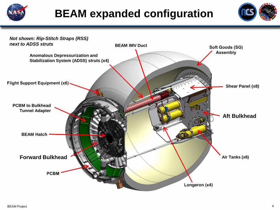
Air Tanks (x8)
BEAM Hatch
Forward Bulkhead
PCBM to Bulkhead
Tunnel Adapter
Anomalous Depressurization and
Stabilization System (ADSS) struts (x4)
BEAM IMV Duct
Shear Panel (x8)
Aft Bulkhead
Not shown: Rip-Stitch Straps (RSS)
next to ADSS struts

BEAM Project
BEAM launched, berthed, and
deployed on ISS
BEAM launched on SpX-8 (April 8, 2016), Dragon/BEAM arrived Node 2 (April
10th), SSRMS extracted BEAM from Dragon Trunk on Node 2 Nadir, moved it to Node 3,
and berthed it on Node 3 Aft port (April 15-16 2016), and fully pressurized on May 28, 2016.
5

6
Ingress #4
Ingress #1-#3
BEAM Ingress Timeline (through 2-years)
Ingress #7
Ingress Date Operations
1-3 June 6-8, 2016 Outfitting interior, installed sensors, and took microbial air/surface samples
4 5-Sep-16
Replaced DIDS battery packs --> DIDS back to nominal ops, reattached 5 accelerations
to shell with Kapton tape, retrieved exposed RAM's for return in Soyuz 46S
5 29-Sep-16
Performed Modal Test; IWIS data not recorded due to bad cable connection,
preemptive Kapton-taping of 7 accelerometers
6 24-Oct-16 RAM install and microbial sampling
7 1-Feb-17 2nd Modal Test, RAM swab and microbial sampling
8 22-Mar-17 RAM swap, microbial sampling, accelerometer inspection
9 28-Apr-17 1st REM shield installed (1.1 mm thick)
10 31-May-17 2nd 3D-printed REM shields (3.3mm thick) installation & new RAMs
11 20-Jun-17 3rd (final) 3D-printed REM shield (10mm thich) installation
12 31-Jul-17 flipped 10 mm dome
13 22-Aug-17 microbial sampling
14 20-Nov-17 removed pressurization tanks, stowage box, cables, …
15 21-Nov-17 installed hardwire sensors, PMA, duct extension, empty M-bags, microbal sampling
16 22-Feb-18 microbial sampling, reattach sensors, remove 10mm REM shield, LEE and CTB stowage
17 18-May-18 WTS 1003 battery replacement, microbial/air sampling
18 TBD LEE removed, DIDS cable swap (extension), DIDS and WTS battery swap
19 TBD Add supplemental BEAM Stowage (up to 109 CTBE).
20 …………………

BEAM Project
BEAM – Microbiological Monitoring
7
August 22, 2017
November 21, 2017
February 22, 2018
May 18, 2018

BEAM Project 8
BEAM Sensor System Overview
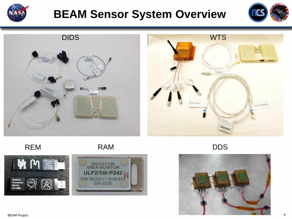
Sensor Parameter Deployment Data Retrieval Previous UseDistributed Impact
Detection System
(DIDS)
Detects structural
impacts to BEAM
Installed pre-launch:
4 transducers on the
bulkheads
Installed on orbit:
12 transducers on the
soft goods
sensor boxes
RF to SSC
(closed hatch)ISS Ultrasonic
Background Noise
Test SDTO
Deployment
Dynamics Sensors
(DDS)
Records acceleration
loads during inflation
stage
3 DDS units and triaxial
accelerometers are
installed prelaunch
USB to SSC
(BEAM ingress)Shuttle Wing
Leading Edge
accelerometers and
Crew Seat DTO
Wireless Temperature
Sensors (WTS)
Monitors temperature
of BEAM surface
(IVA)
4 WTS units Installed
on-orbit (qty 4 RTD
channels each)
RF to SSC
(closed hatch)Shuttle Wireless
Strain Gauge
Instrumentation
System
Radiation
Environment Monitor
(REM)
Monitors radiation
environment internal
to the BEAM structure
2 REM Installed on-orbit USB to SSC
(closed hatch)REM SDTO
Radiation Area
Monitor (RAM)
Passive radiation
monitoring badges
6 RAMs Installed on-
orbit
Replaced and
returned to ground
every Soyuz vehicle
cycle
BEAM Project 9
BEAM Sensor System Overview
DIDS WTS
REM RAM DDS

BEAM Project 10
Deployment Dynamic Sensor (DDS)
Purpose: Used as a technology demonstration for characterizing the BEAM Module deployment
dynamics with accelerometers on the Aft bulkhead surface.
Deployment: Hardware pre-installed prior to launch on Aft bulkhead.
Qty 8 Air
Inflation
Tanks
Qty 3 triaxial
acceleromet
ers
Qty 3
Deployment
Dynamic
Sensor (DDS)
units
Qty 4
single axis
accels
with
cables for
DIDS

BEAM Project
DDS Sensor Results for Deployment
Monitoring
11
The DDS successfully recorded 10 hrs of accelerometer data during the
BEAM deployment.
• Thousands of impulses were measured from the Rip-Stitch Strap (RSS)
stitches popping.
• Max 0.5g peak during initial inflation attempt and max 0.3g during the
final inflation.
• No indication of ADSS struts binding or high transient loads on ISS.
DDS was also used to support Modal testing inside of BEAM.
Inflation Day 1
(~2.5 hours)
Inflation Day 2
(final hour)
Wireless Temperature Sensor (WTS)
12
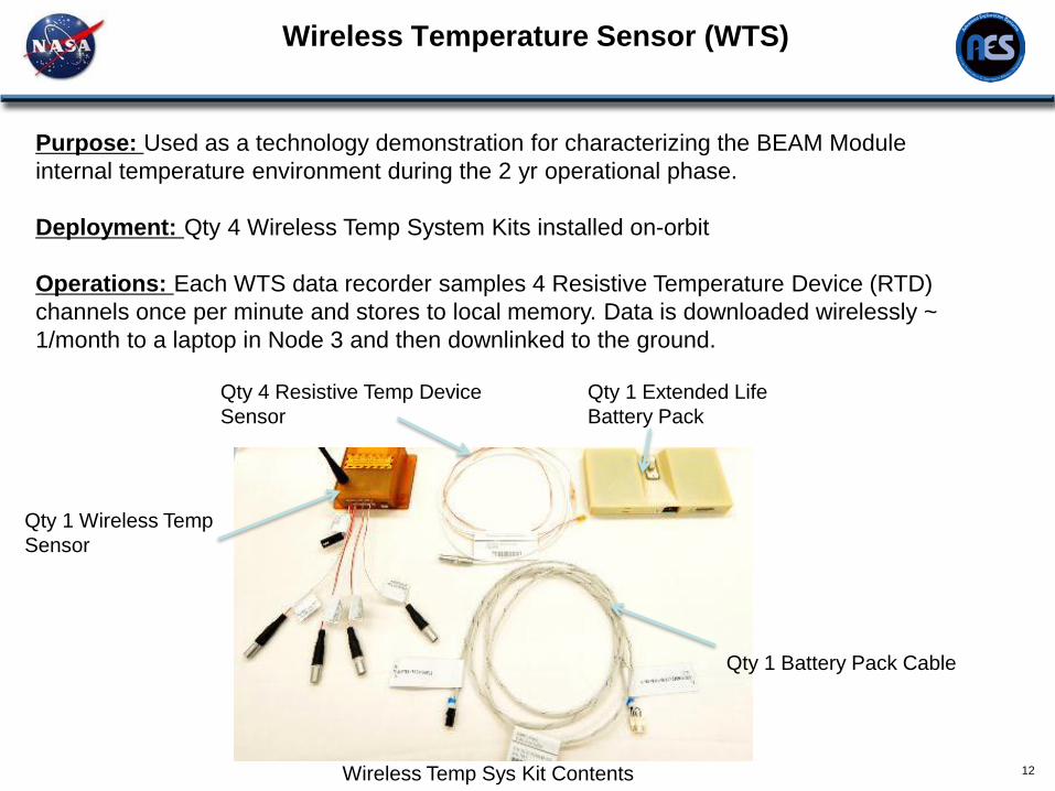
Purpose: Used as a technology demonstration for characterizing the BEAM Module
internal temperature environment during the 2 yr operational phase.
Deployment: Qty 4 Wireless Temp System Kits installed on-orbit
Operations: Each WTS data recorder samples 4 Resistive Temperature Device (RTD)
channels once per minute and stores to local memory. Data is downloaded wirelessly ~
1/month to a laptop in Node 3 and then downlinked to the ground.
Qty 1 Extended Life
Battery Pack
Qty 1 Wireless Temp
Sensor
Wireless Temp Sys Kit Contents
Qty 4 Resistive Temp Device
Sensor
Qty 1 Battery Pack Cable

BEAM Thermal Performance
13
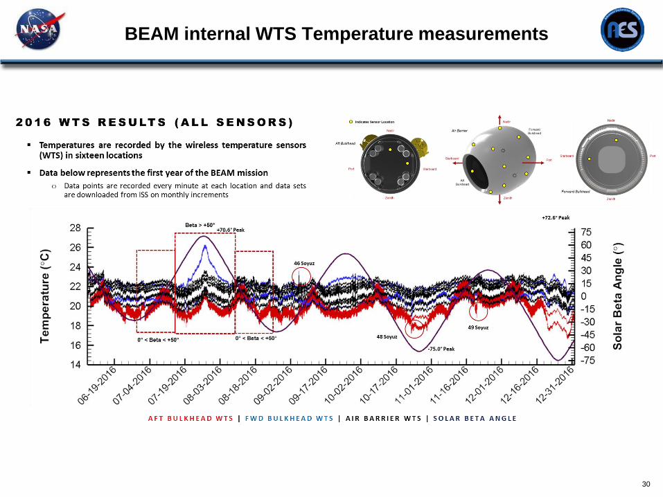
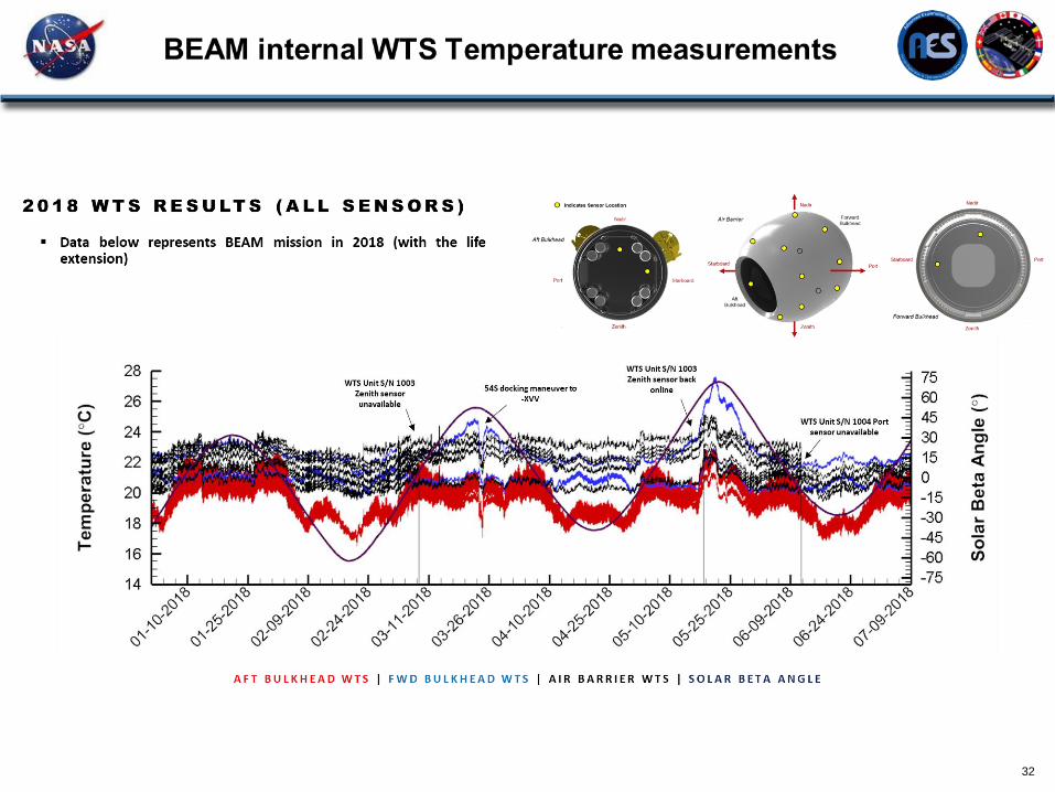
• A total of 16 WTS RTD sensors were installed with tape inside of BEAM.
• 12 sensors were placed radially along the BEAM inner air barrier and 2 sensors on the Forward and Aft
bulkhead surfaced respectively. Approximate locations are shown below.
• Initial pre-expansion internal temperatures measured by the DDS system were significantly warmer than
predicted analysis temperatures which was likely due to the folded soft goods layer creating an additional
thermal isolation not modeled.
• Current model of the Expanded Module tends to under predict the WTS readings.
• BEAM demonstrated adequate thermal control and condensation prevention with unobstructed and partially
obstructed ventilation from the ISS IMV, nominally at 22.6 ºC and 3.4 m³/min, and ISS atmosphere humidity
levels (dew point) from 5.6 to 12.8 ºC (Relative Humidity 33 – 54%)
Locations of the 16 WTS sensors (a) BEAM aft bulkhead, (b) air barrier and (c) forward bulkhead*
* Graphics and data on this slide and the next were provided by the BEAM NASA/JSC Passive Thermal Principle
Investigators John Iovine & William Walker
Distributed Impact Detection System Overview
14
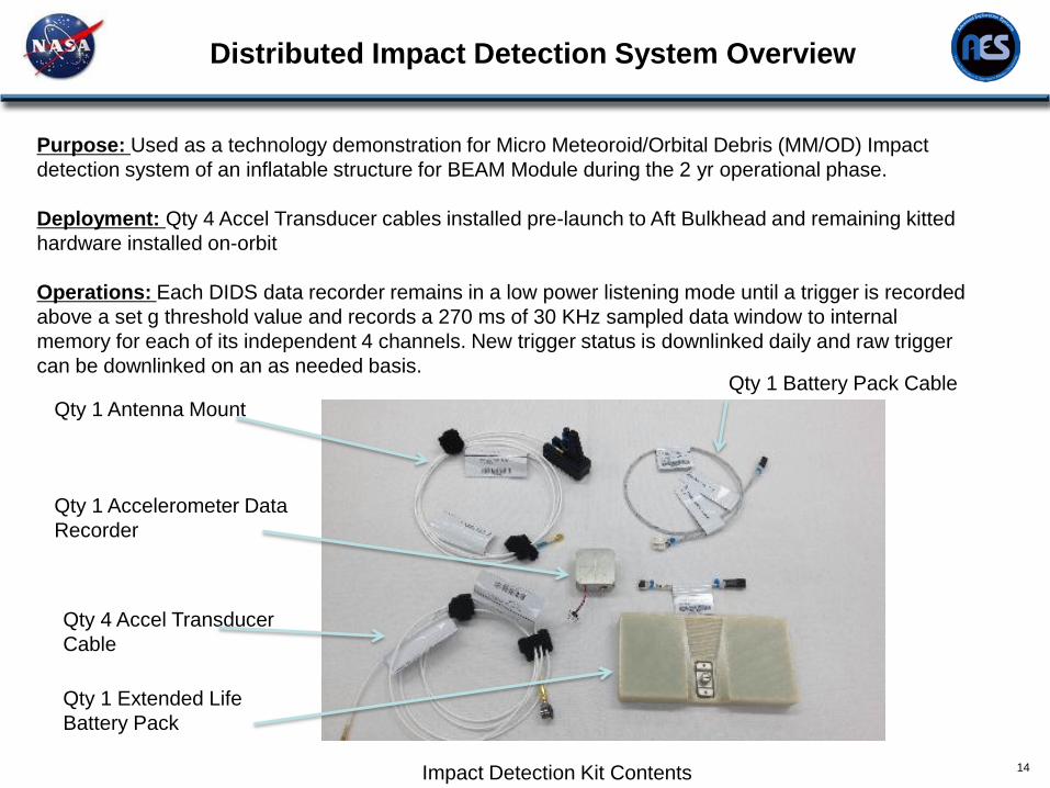
Purpose: Used as a technology demonstration for Micro Meteoroid/Orbital Debris (MM/OD) Impact
detection system of an inflatable structure for BEAM Module during the 2 yr operational phase.
Deployment: Qty 4 Accel Transducer cables installed pre-launch to Aft Bulkhead and remaining kitted
hardware installed on-orbit
Operations: Each DIDS data recorder remains in a low power listening mode until a trigger is recorded
above a set g threshold value and records a 270 ms of 30 KHz sampled data window to internal
memory for each of its independent 4 channels. New trigger status is downlinked daily and raw trigger
can be downlinked on an as needed basis.Qty 1 Battery Pack Cable
Qty 1 Extended Life
Battery Pack
Qty 1 Accelerometer Data
Recorder
Qty 4 Accel Transducer
Cable
Impact Detection Kit Contents
Qty 1 Antenna Mount

Distributed Impact Detection System Overview
15
Detects MM/OD and IVA Events
Uses 3 VDC custom designed external Battery Pack, expected operational
life of 2 years.
Can store 9999 events on an internal memory card
Verified that adhesive attachment method for accelerometers to smooth
surfaces (Bladder) survives HVI impacts.
NOTE: NOT Actual sensor location!
DIDS Sensors locations are for illustration purpose only.
DIDS Sensors are Internal to
Structure.
BEAM air barrier had been pre-marked for
DIDS/WTS sensor installation locations. Sensor locations were configured to ensure
maximum internal coverage and to monitor pre-
flight identified high risk MM/OD impact probability
locations.
12 DIDS piezoelectric accelerometers
were adhered to air barrier via pre-applied
double-sided transfer tape and Kapton
tape by crew

DIDS Sensor Labeling/On-Orbit Installation
16
BEAM Sensor 3D Model ViewBEAM Mock-up ViewNote: Cables attached to inner air barrier with 1
3/8” dia Velcro dots
B
B1W1 B2W2
B3W3B4W4

BEAM Impact Detection Performance Overview
17
Initial DIDS operations required engineering to tweak the trigger threshold
parameters to ensure DIDS accelerometers would not falsely trigger due to
low level ISS background noise being injected into the module structure.
Crew activity induced loads to structure have been routinely recorded during
previous crew ingresses in the module
DIDS operations had to be adjusted initially to disable an internal amplifier
which had been left active and was causing increased power consumption.
BEAM Impact Detection Performance Overview
18
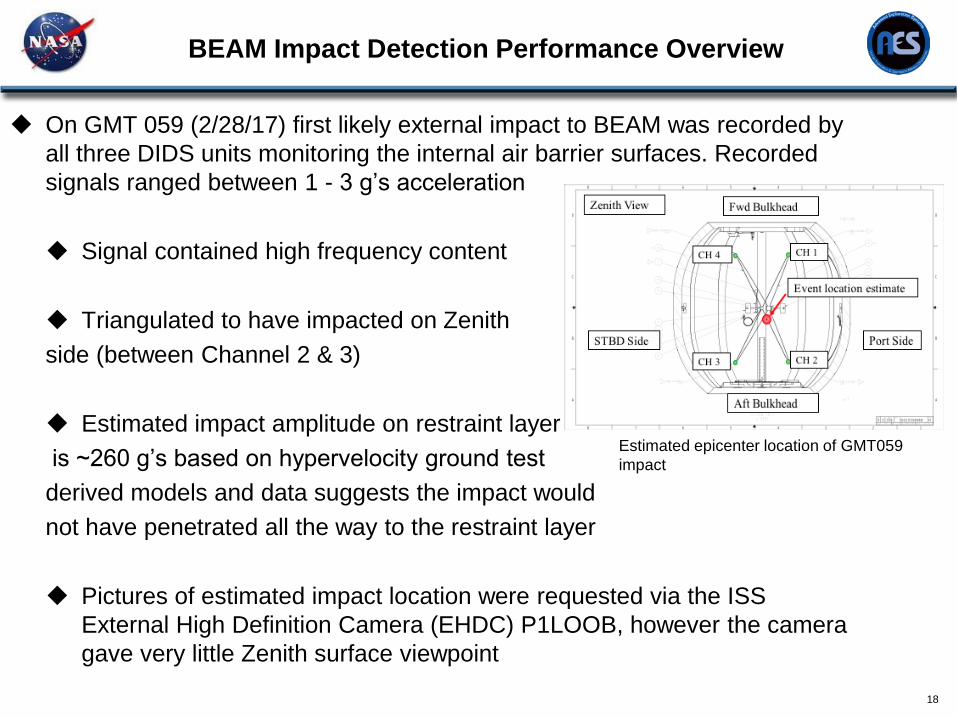
On GMT 059 (2/28/17) first likely external impact to BEAM was recorded by
all three DIDS units monitoring the internal air barrier surfaces. Recorded
signals ranged between 1 - 3 g’s acceleration
Signal contained high frequency content
Triangulated to have impacted on Zenith
side (between Channel 2 & 3)
Estimated impact amplitude on restraint layer
is ~260 g’s based on hypervelocity ground test
derived models and data suggests the impact would
not have penetrated all the way to the restraint layer
Pictures of estimated impact location were requested via the ISS
External High Definition Camera (EHDC) P1LOOB, however the camera
gave very little Zenith surface viewpoint
Estimated epicenter location of GMT059
impact

BEAM Radiation Sensors
19
A total of 6 Passive and 2 active radiation sensors were installed inside of BEAM via
velcro.
The Radiation Environment Monitors (REMs) couples small radiation sensor with
advanced electronics• Consist of a Timepix read-out chip bonded to a 300 µm thick, 2cm2 silicon sensor layer.
• The Timepix provides on-chip data collection and signal digitization within the footprint of each of the individual pixels
in the 256 by 256 pixel matrix
• Power/data provided via USB and connect to Space Station Computer laptop in Node 3
• Provides spectral information (energy deposition as function of particle type and energy) and radiation dose
Radiation Area Monitors (RAMs) came back to ground during nominal ISS Soyuz
return cycle for data evaluation. RAM sensor monitoring discontinued in Dec. 2017.
Passive Instrumentation (RAM)
Active Instrumentation (REM)
Radiation Performance
20
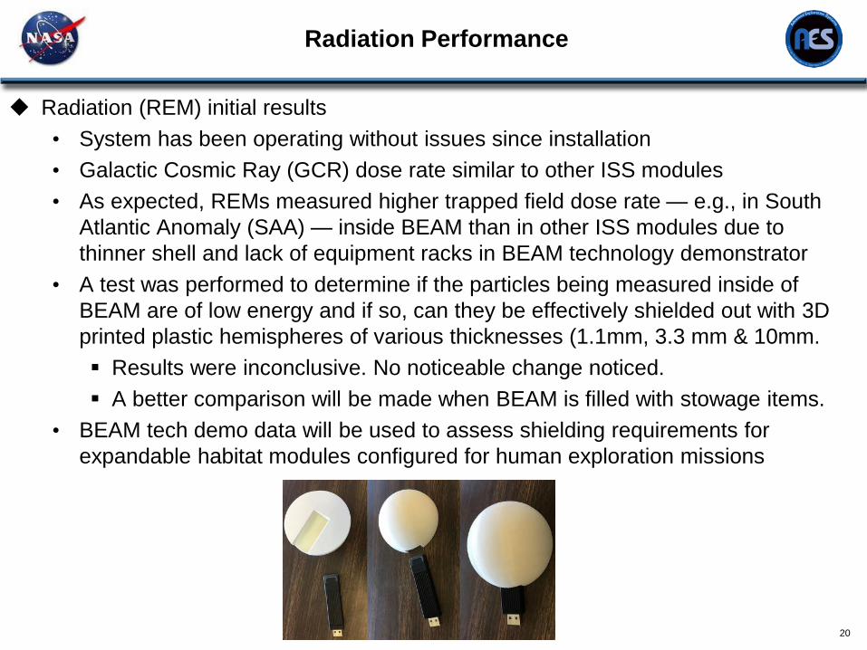
Radiation (REM) initial results
• System has been operating without issues since installation
• Galactic Cosmic Ray (GCR) dose rate similar to other ISS modules
• As expected, REMs measured higher trapped field dose rate — e.g., in South
Atlantic Anomaly (SAA) — inside BEAM than in other ISS modules due to
thinner shell and lack of equipment racks in BEAM technology demonstrator
• A test was performed to determine if the particles being measured inside of
BEAM are of low energy and if so, can they be effectively shielded out with 3D
printed plastic hemispheres of various thicknesses (1.1mm, 3.3 mm & 10mm.
Results were inconclusive. No noticeable change noticed.
A better comparison will be made when BEAM is filled with stowage items.
• BEAM tech demo data will be used to assess shielding requirements for
expandable habitat modules configured for human exploration missions

BEAM Stowage Module Utilization
21
BEAM Contract Updated to support utilization as a stowage module and life
extension
BEAM completed 2-year certified life under original contract
• All milestones met and BEAM performed nominally
BEAM de-outfitted to support utilization as a stowage module
• Removed tanks, stowage box, cables
Converted wireless WTS and DIDS sensors to wired configuration
Extend vent duct to meet air flow requirements
Installed 420 pound failed Latching End Effector (LEE) plus 610 pounds of
cargo inside of BEAM

BEAM Stowage Module Utilization
22
BEAM with 109 CTBE Stowage

BEAM Life Extension through End of ISS Life
23
BEAM meets MMOD penetration requirements through 12/31/2028
BEAM meets stress requirements for a fully loaded (109 CTBE)
configuration
Fully loaded (109 CTBE) BEAM meets fatigue requirements through 2028
ADSS needs to be reinforced in order to meet stress and fatigue
requirements for a fully loaded BEAM in the off-nominal depressurized state
• Currently working on reinforcing ADSS utilizing on-orbit hardware
(repurposed handrails)

BEAM Future Plans & Summary
24
Future Plans
BEAM was originally planned for a 2 yr operational mission to demonstrate
and advance the technology with infrequent human ingresses.
• Utilize BEAM as a stowage module
• Extend BEAM life to end-of-ISS-life
• Conduct additional experiments inside BEAM
Summary
Overall BEAM has been performing beyond expectations!
BEAM has advanced human rated expandable modules to TRL 9 and in the
future should be considered as a solution for volume/mass savings in future
planetary and space exploration applications.
Use BEAM sensor data and lessons learned to fold into future expandable
module design
25
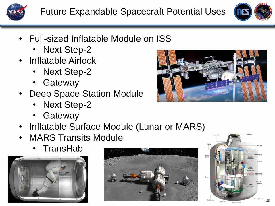
• Full-sized Inflatable Module on ISS
• Next Step-2
• Inflatable Airlock
• Next Step-2
• Gateway
• Deep Space Station Module
• Next Step-2
• Gateway
• Inflatable Surface Module (Lunar or MARS)
• MARS Transits Module
• TransHab
Future Expandable Spacecraft Potential Uses
Team Acknowledgements
26
The authors of this presentation would like to provide a special thanks to the
entire BEAM project team and Bigelow Aerospace.
Specifically the authors would like to acknowledge the following people who
provided BEAM specific performance data:
• Microbial Monitoring Performance – Ariel Macatangay, William Misek & Melanie
Smith
• Deployment Dynamics & Modal Test Results – Michael Grygier
• Thermal Performance – John Iovine, Dr. William Walker, and Zaida Hernandez
• MM/OD Monitoring Performance – Dr. Eric Madaras
• Radiation Sensor System & Performance – Dr. Dan Fry and the entire Space
Radiation Analysis Group (SRAG)
BEAM Project
Backup
27
BEAM Project
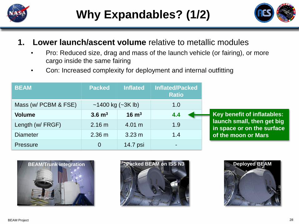
Why Expandables? (1/2)
28
BEAM Packed Inflated Inflated/Packed
Ratio
Mass (w/ PCBM & FSE) ~1400 kg (~3K lb) 1.0
Volume 3.6 m3 16 m3 4.4
Length (w/ FRGF) 2.16 m 4.01 m 1.9
Diameter 2.36 m 3.23 m 1.4
Pressure 0 14.7 psi -
Key benefit of inflatables:
launch small, then get big
in space or on the surface
of the moon or Mars
1. Lower launch/ascent volume relative to metallic modules
• Pro: Reduced size, drag and mass of the launch vehicle (or fairing), or more
cargo inside the same fairing
• Con: Increased complexity for deployment and internal outfitting
BEAM/Trunk integration Packed BEAM on ISS N3 Deployed BEAM
BEAM Project
Why Expandables? (2/2)
29
0
50
100
150
200
250
300
0 50 100 150 200 250 300 350 400
Den
sit
y =
Mass/V
olu
me (
kg
/m3)
Volume (m3)
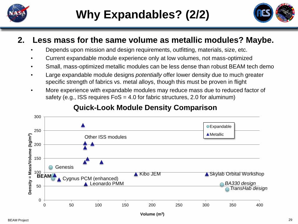
Quick-Look Module Density Comparison
Expandable
Metallic
BEAM
BA330 designTransHab design
Genesis
Leonardo PMM
Skylab Orbital WorkshopKibo JEMCygnus PCM (enhanced)
2. Less mass for the same volume as metallic modules? Maybe.• Depends upon mission and design requirements, outfitting, materials, size, etc.
• Current expandable module experience only at low volumes, not mass-optimized
• Small, mass-optimized metallic modules can be less dense than robust BEAM tech demo
• Large expandable module designs potentially offer lower density due to much greater
specific strength of fabrics vs. metal alloys, though this must be proven in flight
• More experience with expandable modules may reduce mass due to reduced factor of
safety (e.g., ISS requires FoS = 4.0 for fabric structures, 2.0 for aluminum)
Other ISS modules
30
BEAM internal WTS Temperature measurements

31
BEAM internal WTS Temperature measurements
32

BEAM Impact Detection Performance Overview
33
-3
-2
-1
0
1
2
3
0 5 10 15 20 25 30
Am
pli
tude
(g)
Time (msec)
DIDS Unit 1119, 2/28/2017, 34
Ch 2 (g)
2/28/2017at14hrs:11mins:7.189secs
-3
-2
-1
0
1
2
3
0 5 10 15 20 25 30
Am
pli
tude
(g)
Time (msec)
DIDS Unit 1119, 2/28/2017, Event 34
Ch 3 (g)
2/28/2017at14hrs:11mins:7.189secs
-3
-2
-1
0
1
2
3
0 5 10 15 20 25 30
Am
pli
tude
(g)
Time (msec)
DIDS Unit 1119, 2/23/2017, Event 34
Ch 4 (g)
2/28/2017at14hrs:11mins:7.189secs
-3
-2
-1
0
1
2
3
0 5 10 15 20 25 30
Am
pli
tude
(g)
Time (msec)
DIDS Unit 1119, 2/28/2017, Event 34
Ch 1 (g)
2/28/2017at14hrs:11mins:7.189secs
0.0E+00
5.0E-03
1.0E-02
1.5E-02
2.0E-02
0 0.5 1 1.5 2 2.5 3 3.5 4
Am
pli
tude
(g)
Freq. (KHz)
DIDS Unit 1119, 2/28/2017, Event 34
Ch 1 (g)
Ch 2 (g)
Ch 3 (g)
Ch 4 (g)
2/28/2017at14hrs:11mins:7.189secs
Zenith DIDS Frequency
Response
Zenith DIDS Time History (all 4 channels)