atr spent fuel management options study5. dry storage of atr snf at intec’s cpp-749, underground...
TRANSCRIPT
INL/EXT-16-40471
ATR Spent Fuel Management Options Study
Michael J. Connolly Thomas E. Bean Jeffery O. Brower Dale E. Luke M. W. Patterson Alan K. Robb Robert Sindelar Rebecca E. Smith Vincent E. Tonc Julia L. Tripp Philip L. Winston
January 2017

DISCLAIMER This information was prepared as an account of work sponsored by an
agency of the U.S. Government. Neither the U.S. Government nor any agency thereof, nor any of their employees, makes any warranty, expressed or implied, or assumes any legal liability or responsibility for the accuracy, completeness, or usefulness, of any information, apparatus, product, or process disclosed, or represents that its use would not infringe privately owned rights. References herein to any specific commercial product, process, or service by trade name, trade mark, manufacturer, or otherwise, does not necessarily constitute or imply its endorsement, recommendation, or favoring by the U.S. Government or any agency thereof. The views and opinions of authors expressed herein do not necessarily state or reflect those of the U.S. Government or any agency thereof.
INL/EXT-16-40471
ATR Spent Fuel Management Options Study
Michael J. Connolly (lead) Thomas E. Bean
Jeffrey O. Brower Dale E. Luke
M. W. Patterson Alan K. Robb
Robert Sindelar Rebecca E. Smith Vincent F. Tonc
Julia L. Tripp Philip L. Winston
January 2017
Idaho National Laboratory Idaho Falls, Idaho 83415
http://www.inl.gov
Prepared for the U.S. Department of Energy Office of Nuclear Energy
Under DOE Idaho Operations Office Contract DE-AC07-05ID14517

ATR Spent Fuel Management Options Study
INL/EXT-16-40471
January 2017
Approved by:
1/23/17 Sean O’Kelly Associate Laboratory Director, Advanced Test Reactor
Date
1/26/17 Juan Alvarez Deputy Laboratory Director
Date


v
EXECUTIVE SUMMARY The Advanced Test Reactor (ATR) is a materials and fuels test nuclear
reactor that performs irradiation services for the U.S. Department of Energy (DOE) Office of Nuclear Energy, Naval Reactors, the National Nuclear Security Administration, and other commercial and international customers. ATR achieved initial criticality in 1967 and is expected to operate in support of needed missions until 2050 or beyond. It is anticipated that ATR will generate approximately 105 spent nuclear fuel (SNF) elements per year through the year 2050. Idaho National Laboratory (INL) currently stores 2008 ATR SNF elements in dry storage, 976 in wet storage, and expects to have 1,000 in wet storage before January 2017.
A capability gap exists at INL for long-term (i.e., greater than the year 2050) management, in compliance with the 1995 Idaho Settlement Agreement,a until a repository is open. INL has significant wet and dry storage capabilities that are owned by DOE’s Office of Environmental Management and operated and managed by Fluor Idaho, which include the Idaho Nuclear Technology and Engineering Center’s (INTEC’s) CPP-666, CPP-749, and CPP-603. In addition, INL has other capabilities owned by DOE’s Office of Nuclear Energy and operated and managed by the Battelle Energy Alliance (BEA) that are located at the Materials and Fuel Complex (MFC). Additional storage capabilities are located on the INL Site at the Naval Reactors Facility (NRF). Current INL SNF management planning, as defined in the Fluor Idaho contract, shows that INTEC’s capacity for dry fuel storage, currently used for ATR SNF, will be nearly full after transfer of 1,000 ATR SNF elements from wet storage. It is estimated the ATR canal will have 400 storage positions available after the additional 24 elements are transferred to wet storage at INTEC. Assuming no additional transfers of ATR SNF elements after reaching 1,000 elements in wet storage at INTEC and also that 105 ATR SNF elements are generated annually, it is estimated that the ATR canal will reach capacity in the 2020 timeframe.
The DOE Idaho Office of Nuclear Energy tasked BEA with identifying and analyzing options that have the potential to fill this capability gap. BEA assembled a team comprised of SNF management experts from Fluor Idaho, Savannah River National Laboratory, INL/BEA, and the MITRE Corp, with the objective of developing and analyzing options to fill the capability gap. This management options analysis is not an alternatives analysis as defined by DOE Order 413.3B; rather it is a management evaluation of potential gaps and interim and long-term actions needed to fill the capability gap.
Since 2006, a number of plans, studies, evaluations, and initiatives were developed and implemented in regard to management of ATR SNF and in response to the 1995 Idaho Settlement Agreement and regulatory requirements. However, minimal action was taken in response to these previous studies. Based on this information, current regulatory and operating conditions and constraints, and discussions with DOE Idaho Operations Office, Fluor Idaho, and BEA leadership, the following options were identified and evaluated:
1. Ship to the DOE Savannah River Site (SRS) for reprocessing at H-Canyon.
a 1995 Settlement Agreement and Consent Order in the matter entitled Public Service Company of Colorado v. Batt, CV-91-0035-S-EJL and CV 91-0054-S-EJL.
vi
2. Dry storage at NRF in a road-ready configuration with a CPP-666 Fuel Storage Area (FSA) interface.
3. Dry storage at NRF in a road-ready configuration with dry transfer at ATR.
4. Dry storage at MFC-771, Radioactive Scrap and Waste Facility.
5. Dry storage of ATR SNF at INTEC’s CPP-749, Underground Fuel Storage Facility (UGFSF).
6. Dry storage of ATR SNF at INTEC’s CPP-603, Irradiated Fuel Storage Facility (IFSF).
7. Consolidate and optimize INTEC dry storage (transfer Peach Bottom SNF from IFSF to UGFSF and transfer ATR SNF from FSA and the ATR canal to IFSF).
8. Dry storage at ATR using commercially available systems.
9. Dry storage at ATR using modular dry canister approach.
10. Processing of ATR SNF at INTEC FSA Fluorinel Dissolution Process Cell using the ZIRCEX process.
11. Extended wet storage of ATR SNF at FSA.
12. Conversion of FSA Wet Storage Pool to Dry Storage.
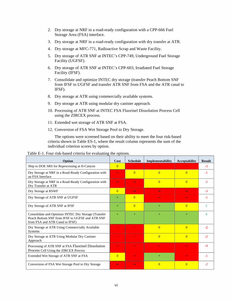
The options were screened based on their ability to meet the four risk-based criteria shown in Table ES-1, where the result column represents the sum of the individual criterion scores by option.
Table E-1. Four risk-based criteria for evaluating the options.
Option Cost Schedule Implementability Acceptability Result Ship to DOE SRS for Reprocessing at H-Canyon 0 ─ ─ ─ -3
Dry Storage at NRF in a Road-Ready Configuration with an FSA Interface
─ 0 0 0 -1
Dry Storage at NRF in a Road-Ready Configuration with Dry Transfer at ATR
─ ─ 0 0 -2
Dry Storage at RSWF 0 ─ ─ ─ -3
Dry Storage of ATR SNF at UGFSF + 0 ─ ─ -1
Dry Storage of ATR SNF at IFSF + 0 + 0 2
Consolidate and Optimize INTEC Dry Storage (Transfer Peach Bottom SNF from IFSF to UGFSF and ATR SNF from FSA and ATR Canal to IFSF)
+ + + + 4
Dry Storage at ATR Using Commercially Available Systems
─ ─ 0 0 -2
Dry Storage at ATR Using Modular Dry Canister Approach
─ ─ 0 0 -2
Processing of ATR SNF at FSA Fluorinel Dissolution Process Cell Using the ZIRCEX Process
─ ─ ─ ─ -4
Extended Wet Storage of ATR SNF at FSA 0 ─ + ─ -1
Conversion of FSA Wet Storage Pool to Dry Storage ─ ─ 0 0 -2
vii
Based on the results of the screening process, the preferred option is dry
storage at INTEC via consolidation and optimization of the CPP-603 IFSF and UGFSF existing capacity. This option has many benefits that include the following: (1) supports compliance with the Idaho Settlement Agreement to remove all SNF from wet storage by December 31, 2023; (2) supports ATR operation to at least 2050; (3) optimizes utilization of existing infrastructure; (4) is not reliant on infrastructure and capabilities external to INL; (5) no impact or minimal impact to continued ATR operations; (6) consolidates storage of INL SNF not destined for onsite treatment; (7) minimizes near and long-term cost and avoids capital asset investment; and (8) least amount of overall risk.
All evaluated options have risks associated with filling the identified capability gap and continued operation of ATR that will require action to mitigate any potential impact. As with all dry storage options, there are potential concerns about the future structural integrity of the fuel elements due to the potential for cladding degradation that may impact future handling in support of final packaging and disposition. This concern has many factors associated with it and the DOE SNF Working Group is studying technical issues associated with long-term (i.e., greater than 50-year storage) of aluminum-clad SNF. The current CPP-603 IFSF safety analysis report and the analyses in support of the DOE standard spent fuel canister indicate no significant technical issues associated with corrosion and resulting fuel element structural integrity for controlled storage up to 50 years. The SNF Working Group is reviewing all documents associated with CPP-603 and the DOE standardized spent fuel canister, as well as other national laboratory studies and other pertinent studies as a basis for its report. The SNF Working Group should have a report issued in early 2017. Results from this study can be incorporated during planning of the preferred option and ensure needed mitigating actions are implemented as appropriate.
Overall risk associated with the preferred option is easily manageable for many reasons. The fundamental basis for the preferred option is the ability to increase CPP-603 IFSF canister wattage limits and fuel element loading. The wattage limit assumed in this report is very conservative compared with the anticipated allowable limit, which is supported by the current facility thermal inventory and estimated maximum fuel temperature. Risk associated with reliance upon the ATR canal for mandatory cooling can, in the near term (up to approximately the year 2022), be mitigated by having CPP-666 FSA as a back-up if needed. Developing additional ATR canal storage capacity through canal cleanup and more diligent management of no-longer-needed irradiated fuel elements may be required. It is anticipated that ATR canal operations management will have approximately 2 years to prepare for handling the High-Load Charger and, if there are issues, the temporary option of using the ATR cask for shipment to CPP-666 for transfer into the High-Load Charger for transfer to CPP-603 IFSF should be available.
It is recommended that the DOE Idaho Operations Office provide direction to BEA and Fluor Idaho to complete detailed planning, including cost, schedule, needed engineering analysis, and other activities necessary to implement the preferred option.

viii

ix
ACKNOWLEDGEMENTS The authors extend their gratitude to Dr. Paul Murray, AREVA, for valuable
insight and review of several spent fuel handling concepts and sharing of AREVA technical reports generated for the U.S. Department of Energy’s Office of Nuclear Energy Spent Fuel Technology Program, and to Phil Wheatley, INL retired, and Bill Hurt, INL retired, for insightful conversations regarding spent nuclear fuel management issues and technology. Acknowledgement and thanks to Dr. Sam Steckley, MITRE Corp.; Jay Roach, Nexergy Technical; Julie Conner, U.S. Department of Energy Idaho Operations Department; Chad Miltenberger, U.S. Department of Energy Office of Naval Reactors; Adrian Collins, Battelle Energy Alliance; Robert Miklos, Battelle Energy Alliance; and Russell Cottam, Fluor Idaho.

x
xi
CONTENTS
EXECUTIVE SUMMARY .......................................................................................................................... v
ACKNOWLEDGEMENTS ......................................................................................................................... ix
ACRONYMS ............................................................................................................................................ xvii
1. INTRODUCTION .............................................................................................................................. 1
1.1 Description of Issue ................................................................................................................. 1
1.2 Identification of Management Options .................................................................................... 2
1.3 Criteria and Approach Used for Options Analysis ................................................................... 3
1.4 General Assumptions for Options Analysis ............................................................................. 4
2. BACKGROUND ................................................................................................................................ 5
2.1 Advanced Test Reactor Spent Nuclear Fuel Storage and Generation Rates ............................ 6
2.2 General Characteristics of Advanced Test Reactor Spent Nuclear Fuel ................................. 6
2.3 Potential Long-Term Dry Storage Technical Issues ................................................................ 6
2.4 Previous Advanced Test Reactor Spent Nuclear Fuel Management Options Studies ............. 9
2.5 Advanced Test Reactor Spent Nuclear Fuel Volume Expected through 2050 ....................... 9
3. SELECTION OF MANAGEMENT OPTIONS FOR EVALUATION ........................................... 11
3.1 Description of Options ........................................................................................................... 11
3.1.1 Ship to the Department of Energy Savannah River Site for Reprocessing at H-Canyon .................................................................................................................. 11
3.1.2 Dry Storage at the Naval Reactors Facility in a Road-Ready Configuration with a Fuel Storage Area Interface............................................................................ 12
3.1.3 Dry Storage at the Naval Reactors Facility in a Road-Ready Configuration with Dry Transfer at the Advanced Test Reactor ...................................................... 13
3.1.4 Dry Storage at Idaho National Laboratory’s Radioactive Scrap and Waste Facility ...................................................................................................................... 14
3.1.5 Dry Storage of Advanced Test Reactor Spent Nuclear Fuel at the Underground Fuel Storage Facility ........................................................................... 15
3.1.6 Dry Storage of Advanced Test Reactor Spent Nuclear Fuel at the Irradiated Fuel Storage Facility ................................................................................................. 16
3.1.7 Consolidate and Optimize INTEC Dry Storage: Transfer Peach Bottom Spent Nuclear Fuel from Irradiated Fuel Storage Facility to Underground Fuel Storage Facility and Transfer Advanced Test Reactor Spent Nuclear Fuel from Fuel Storage Area and the Advanced Test Reactor Canal to Irradiated Fuel Storage Facility ................................................................................. 17
xii
3.1.8 Dry Storage at the Advanced Test Reactor using Commercially Available Systems ..................................................................................................................... 18
3.1.9 Dry Storage at the Advanced Test Reactor Using a Modular Dry Canister Approach ................................................................................................................... 19
3.1.10 Processing of Advanced Test Reactor Spent Nuclear Fuel at FSA Flourinel Dissolution Process Cell using the ZIRCEX Process ............................................... 20
3.1.11 Extended Wet Storage of Advanced Test Reactor Spent Nuclear Fuel at Idaho Nuclear Technology and Engineering Center Fuel Storage Area ................... 22
3.1.12 Conversion of Idaho Nuclear Technology and Engineering Center Fuel Storage Area Wet Storage Pool to Dry Storage ........................................................ 22
3.2 Pre-Screening of Options ....................................................................................................... 23
4. SPENT NUCLEAR FUEL MANAGEMENT OPTIONS ANALYSIS – EVALUATIONS ........... 26
4.1 Detailed Analysis of Selected Option – Consolidation and Optimization of CPP-603 and CPP-749 .......................................................................................................................... 26
4.1.1 Strategies and Assumptions ...................................................................................... 26 4.1.2 Cost ........................................................................................................................... 27 4.1.3 Risk ........................................................................................................................... 28 4.1.4 Complexity ................................................................................................................ 29 4.1.5 Stakeholder Values ................................................................................................... 29 4.1.6 Regulatory Compliance ............................................................................................. 29 4.1.7 Strategy ..................................................................................................................... 29
5. SUMMARY AND RECOMMENDATIONS .................................................................................. 30
Appendix A,Option 1: Ship to the Savannah River Site for Reprocessing in H-Canyon ........................... 33
Appendix B, Option 2: Dry Storage at NRF in a Road-Ready Configuration with an FSA Interface ............................................................................................................................................ 45
Appendix C, Option 3: Dry Storage at NRF in a Road-Ready Configuration with a Dry Transfer at ATR .............................................................................................................................................. 57
Appendix D, Dry Storage at RSWF ............................................................................................................ 71
Appendix E, Option 5: Dry Storage of ATR SNF at UGFSF ..................................................................... 83
Appendix F, Option 6: Dry Storage of ATR SNF at IFSF .......................................................................... 93
Appendix G, Option 7: Consolidate and Optimize INTEC Dry Storage: Transfer Peach Bottom SNF from IFSF to UGFSF and Transfer ATR SNF from FSA and ATR Canal to IFSF ............... 103
Appendix H, Option 8: Dry Storage at ATR Using Commercially Available Systems ........................... 117
Appendix I, Option 9: Dry Storage at ATR using a Modular Dry Canister Approach ............................. 127
Appendix J, Option 10: Processing of ATR SNF at the FSA FDP Cell using the ZIRCEX Process ...... 137
Appendix K, Option 11: Extended Wet Storage of ATR SNF at FSA ..................................................... 155

xiii
Appendix L, Option 12: Conversion of the FSA Wet Storage Pool to Dry Storage ................................. 165
Appendix M, Discriminators and Screening Criteria ................................................................................ 179
FIGURES
Figure 1. Dimensions and configuration of ATR SNF element. ................................................................... 8
Figure 2. Logic diagram for INL to SRS SNF exchange. ........................................................................... 11
Figure 3. Transfer to road-ready dry storage at NRF via FSA. ................................................................... 12
Figure 4. Transfer to road-ready dry storage at NRF via a new DTS. ........................................................ 13
Figure 5. Transfer to RSWF for interim below-ground dry storage. .......................................................... 14
Figure 6. Transfer from IFSF to UGFSF for interim below-ground dry storage. ....................................... 15
Figure 7. Transfer from FSA to IFSF. ........................................................................................................ 17
Figure 8. Consolidation and optimization of IFSF and UGFSF for interim storage. .................................. 18
Figure 9. Construct commercial dry storage at the ATR Complex. ............................................................ 19
Figure 10. Construct dry canister modular storage (non-commercial) at ATR. ......................................... 20
Figure 11. Construct ZIRCEX process in FSA to reprocess ATR SNF. .................................................... 21
Figure 12. Extend wet storage in FSA until new conditioning capability is constructed. .......................... 22
Figure 13. Modification of FSA for dry storage and packaging. ................................................................ 23
Figure A-1. Logic diagram for Option 1. .................................................................................................... 35
Figure A-2. Pictures of L-Basin and H-Canyon.......................................................................................... 36
Figure A-3. CPP-666 facility overview. ..................................................................................................... 38
Figure A-4. Option 1 timetable. .................................................................................................................. 43
Figure B-1. Logic diagram for Option 2. .................................................................................................... 47
Figure B-2. Loading operation (underwater) at CPP-666 must put an ATR SNF element in each of two sides of a divided sleeve; each sleeve in a can and eight cans in a basket for (two to three) baskets of 16 elements each to be accepted in LCC for transfer and loading (i.e., three baskets, assumed 48 elements total) into a dry storage canister to be dried and stored at NRF. ...................................................................................................................... 48
Figure B-3. Sleeve loading station (at INTEC or within the new DTS at ATR). ....................................... 48
xiv
Figure B-4. Baskets accept eight sleeves (each in its own can). ................................................................. 49
Figure B-5. Load sealed canister into overpack. ......................................................................................... 49
Figure B-6. Crawler or air pallets move overpack to storage location. ...................................................... 50
Figure B-7. Dry storage location (indoors for weather protection)............................................................. 50
Figure B-8. Option 2 timetable. .................................................................................................................. 54
Figure C-1. Logic diagram for Option 3. .................................................................................................... 59
Figure C-2. Sleeve loading station (concept). ............................................................................................. 60
Figure C-3. Baskets accept eight sleeves (each in its own can). ................................................................. 60
Figure C-4. PMB basket (similar concept, but without sleeve divider and without can). .......................... 61
Figure C-5. Load sealed canister into overpack. ......................................................................................... 62
Figure C-6. Crawler or air pallets move overpack to storage location. ...................................................... 62
Figure C-7. Dry storage location (indoors for weather protection)............................................................. 63
Figure C-8. Option 3 timetable. .................................................................................................................. 68
Figure D-1. Option 4 logic diagram. ........................................................................................................... 73
Figure D-2. RSWF layout. .......................................................................................................................... 74
Figure D-3. The facility, MFC-771, under construction, circa 1964. ......................................................... 76
Figure D-4. Waste package transfer to the facility, MFC-771. ................................................................... 76
Figure D-5. Waste package loading at the facility, MFC-771. ................................................................... 77
Figure D-6. Option 4 timetable. .................................................................................................................. 80
Figure E-1. Logic diagram for Option 5. .................................................................................................... 85
Figure E-2. Layout of CPP-749. ................................................................................................................. 85
Figure E-3. Option 5 timetable. .................................................................................................................. 90
Figure F-1. Logic diagram for Option 6. .................................................................................................... 95
Figure F-2. Option 6 timetable. ................................................................................................................. 101
Figure G-1. Logic diagram for Option 7. .................................................................................................. 105
Figure G-2. Layout of CPP-603. ............................................................................................................... 106
xv
Figure G-3. Layout of CPP-749. ............................................................................................................... 106
Figure G-4. Peach Bottom Basket Drawing# 500214. .............................................................................. 107
Figure G-5. Option 7 timetable. ................................................................................................................ 114
Figure H-1. Logic diagram for Option 8. .................................................................................................. 119
Figure H-2. Three vendors, concrete silos, bunkers, or vaults. ................................................................. 120
Figure H-3. Option 8 timetable. ................................................................................................................ 124
Figure I-1. Logic diagram for Option 9. ................................................................................................... 130
Figure I-2. Artist’s concept of a drying and storage facility. .................................................................... 130
Figure I-3. Option 9 timetable................................................................................................................... 134
Figure J-1. Logic diagram for Option 10. ................................................................................................. 139
Figure J-2. Depiction of fluidized beds for the hydrochlorination, pyrohydrolysis, and elutriation steps. ......................................................................................................................................... 140
Figure J-3. 1960s era ZIRCEX pilot plant was successfully run at Argonne National Laboratory. ......... 141
Figure J-4. Equipment used for laboratory-scale testing of Zr-clad fuels. ................................................ 142
Figure J-5. ZIRCEX pilot plant................................................................................................................. 143
Figure J-6. Layout of ZIRCEX pilot plant and supporting equipment at CPP-653. ................................. 144
Figure J-7. FDP hot cell. ........................................................................................................................... 146
Figure J-8. Technology readiness level timeline. ..................................................................................... 149
Figure J-9. Option 10 timetable. ............................................................................................................... 151
Figure K-1. Option 11 logic diagram. ....................................................................................................... 157
Figure K-2. CPP-666 wet storage general pool layout. ............................................................................ 157
Figure K-3. CPP-666 facility overview. ................................................................................................... 158
Figure K-4. Option 11 timetable. .............................................................................................................. 162
Figure L-1. Pool layout. ............................................................................................................................ 168
Figure L-2. General canister cutaway and lid plug-purge/vent connections. ............................................ 169
Figure L-3. Generic annular transfer cask concept. .................................................................................. 170
Figure L-4. Nominal transfer sequence. .................................................................................................... 171
xvi
Figure L-5. Option 11 logic diagram. ....................................................................................................... 172
Figure L-6. Facility layout. ....................................................................................................................... 173
Figure L-7. View of fuel storage pools looking south. ............................................................................. 174
Figure L-8. Option 11 timetable. .............................................................................................................. 177
TABLES
Table E-1. Four risk-based criteria for evaluating the options. .................................................................... vi
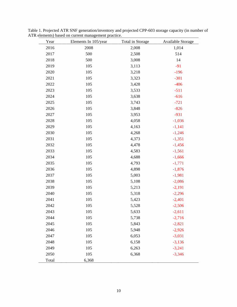
Table 1. Projected ATR SNF generation/inventory and projected CPP-603 storage capacity (in number of ATR elements) based on current management practice. ........................................... 10
Table 2. Relative risk criteria for options. .................................................................................................. 24
Table 3. Summary results of the pre-screening step. .................................................................................. 25
Table 4. High-level risks and preliminary mitigation strategies. ................................................................ 28
Table F-1. CPP-603 ATR SNF inventory and storage needs with 24 elements per position. .................... 99
Table G-1. ATR SNF inventory and storage needs at CPP-603 with 24 elements per position allowing for space vacated by consolidation of Peach Bottom Fuel at CPP-749. .................... 111
Table J-1. Estimated time to process a batch of ATR fuel. ....................................................................... 145
Table J-2. Estimated yearly processing rates. ........................................................................................... 145
Table M-1. Option discriminators, criteria, and factors for comparison of relative risk. ......................... 182
Table M-2. Consolidated criteria of cost, acceptability, implementability, and schedule. ....................... 183
xvii
ACRONYMS ATR Advanced Test Reactor
BEA Battelle Energy Alliance, LLC
CACL contractor-approved cask list
CAFL contractor-approved fuel list
DOE U.S. Department of Energy
DTS dry transfer system
EBR-II Experimental Breeder Reactor-II
EIS environmental impact statement
EM Office of Environmental Management
FCS fuel conditioning station
FDP Fluorinel Dissolution Process
FSA Fuel Storage Area
HLW high-level waste
HVAC heating, ventilating, and air conditioning
ICP Idaho Cleanup Project
IFSF Irradiated Fuel Storage Facility
INL Idaho National Laboratory
INTEC Idaho Nuclear Technology and Engineering Center
ISA Idaho Settlement Agreement
ISFF Idaho Spent Fuel Facility
LCC large cell cask
LWT light-weight truck
MFC Materials and Fuels Complex
NAC NAC International (formerly, Nuclear Assurance Corporation International)
NE Office of Nuclear Energy
NEPA National Environmental Policy Act
NNSA National Nuclear Security Administration
NRF Naval Reactors Facility
PCS permanent containment structure
RCRA Resource Conservation and Recovery Act
RSWF Radioactive Scrap and Waste Facility
SBTC shielded basket transfer container
SFC spent fuel canister

xviii
SNF spent nuclear fuel
SRS Savannah River Site
UGFSF Underground Fuels Storage Facility
1
ATR Spent Fuel Management Options Study 1. INTRODUCTION
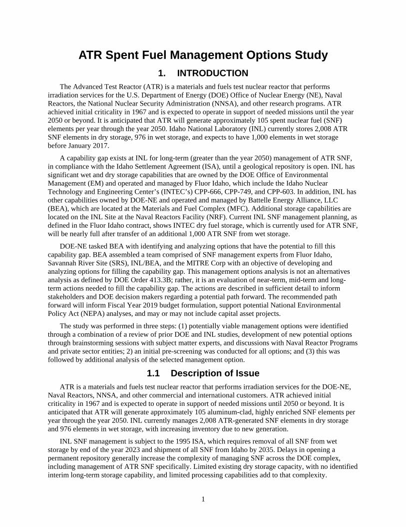
The Advanced Test Reactor (ATR) is a materials and fuels test nuclear reactor that performs irradiation services for the U.S. Department of Energy (DOE) Office of Nuclear Energy (NE), Naval Reactors, the National Nuclear Security Administration (NNSA), and other research programs. ATR achieved initial criticality in 1967 and is expected to operate in support of needed missions until the year 2050 or beyond. It is anticipated that ATR will generate approximately 105 spent nuclear fuel (SNF) elements per year through the year 2050. Idaho National Laboratory (INL) currently stores 2,008 ATR SNF elements in dry storage, 976 in wet storage, and expects to have 1,000 elements in wet storage before January 2017.
A capability gap exists at INL for long-term (greater than the year 2050) management of ATR SNF, in compliance with the Idaho Settlement Agreement (ISA), until a geological repository is open. INL has significant wet and dry storage capabilities that are owned by the DOE Office of Environmental Management (EM) and operated and managed by Fluor Idaho, which include the Idaho Nuclear Technology and Engineering Center’s (INTEC’s) CPP-666, CPP-749, and CPP-603. In addition, INL has other capabilities owned by DOE-NE and operated and managed by Battelle Energy Alliance, LLC (BEA), which are located at the Materials and Fuel Complex (MFC). Additional storage capabilities are located on the INL Site at the Naval Reactors Facility (NRF). Current INL SNF management planning, as defined in the Fluor Idaho contract, shows INTEC dry fuel storage, which is currently used for ATR SNF, will be nearly full after transfer of an additional 1,000 ATR SNF from wet storage.
DOE-NE tasked BEA with identifying and analyzing options that have the potential to fill this capability gap. BEA assembled a team comprised of SNF management experts from Fluor Idaho, Savannah River Site (SRS), INL/BEA, and the MITRE Corp with an objective of developing and analyzing options for filling the capability gap. This management options analysis is not an alternatives analysis as defined by DOE Order 413.3B; rather, it is an evaluation of near-term, mid-term and long-term actions needed to fill the capability gap. The actions are described in sufficient detail to inform stakeholders and DOE decision makers regarding a potential path forward. The recommended path forward will inform Fiscal Year 2019 budget formulation, support potential National Environmental Policy Act (NEPA) analyses, and may or may not include capital asset projects.
The study was performed in three steps: (1) potentially viable management options were identified through a combination of a review of prior DOE and INL studies, development of new potential options through brainstorming sessions with subject matter experts, and discussions with Naval Reactor Programs and private sector entities; 2) an initial pre-screening was conducted for all options; and (3) this was followed by additional analysis of the selected management option.
1.1 Description of Issue ATR is a materials and fuels test nuclear reactor that performs irradiation services for the DOE-NE,
Naval Reactors, NNSA, and other commercial and international customers. ATR achieved initial criticality in 1967 and is expected to operate in support of needed missions until 2050 or beyond. It is anticipated that ATR will generate approximately 105 aluminum-clad, highly enriched SNF elements per year through the year 2050. INL currently manages 2,008 ATR-generated SNF elements in dry storage and 976 elements in wet storage, with increasing inventory due to new generation.
INL SNF management is subject to the 1995 ISA, which requires removal of all SNF from wet storage by end of the year 2023 and shipment of all SNF from Idaho by 2035. Delays in opening a permanent repository generally increase the complexity of managing SNF across the DOE complex, including management of ATR SNF specifically. Limited existing dry storage capacity, with no identified interim long-term storage capability, and limited processing capabilities add to that complexity.
2
ATR SNF has potential long-term storage issues such as deterioration of the aluminum cladding, which includes clad thinning due to corrosion, erosion, pitting, and formation of surface corrosion compounds from service in the reactor that degrade the cladding’s performance. Corrosion and corrosion-related hydrogen generation during water cooling, wet storage, and long-term dry storage can further degrade the storage environment and complicate long-term storage.
INL wet and dry storage capabilities are funded and managed by different DOE offices and different INL contractors. The Idaho Clean-up Project (ICP) core contract is funded by DOE-EM and the facilities are managed by Fluor Idaho under a contract that includes dry storage at INTEC’s CPP-603, Irradiated Fuel Storage Facility (IFSF). CPP-603 currently stores 2,008 ATR SNF fuel elements. An additional 976 ATR SNF elements, owned by DOE-NE, are stored in the INTEC CPP-666, Fuel Storage Area (FSA), pool. The ATR Canal has 876 storage locations for irradiated fuel and as June 8, 2016, had a projected storage capacity of 411 elements after future transfer of 40 elements to CPP-666 FSA.b
The ICP core contract requires transfer of 1,000 ATR SNF elements from FSA to dry storage at IFSF by the end of 2020. Currently, there is capacity at IFSF to receive these 1,000 ATR SNF elements without reconfiguration of the current SNF inventory, but there is insufficient capacity for the newly generated ATR SNF.
1.2 Identification of Management Options A variety of management options were considered for this management options analysis. Not all
management options considered were standalone options capable of filling the identified need/gap for long-term management of ATR SNF. However, select combination(s) of options could provide effective long-term management of ATR SNF. The management options are summarized in Section 3 and then provided in more detail in the appendices. Interim actions for maximizing the existing INL capacity are common to all processing options. Unless specifically noted, all options assumed that 1,000 ATR SNF elements currently in wet storage at CPP-666 or in the ATR canal would be transferred to dry storage at CPP-603 as currently planned. The management options considered for evaluation are as follows:
1. Ship to SRS for reprocessing at H-Canyon.
2. Dry storage at NRF in a road-ready configuration with an FSA interface.
3. Dry storage at NRF in a road-ready configuration with a dry transfer at ATR.
4. Dry storage at Radioactive Scrap and Waste Facility (RSWF).
5. Dry storage of ATR SNF at INTEC CPP-749, Underground Fuel Storage Facility (UGFSF).
6. Dry storage of ATR SNF at IFSF.
7. Consolidate and optimize INTEC dry storage (transfer Peach Bottom SNF from IFSF to UGFSF and transfer ATR SNF from FSA and the ATR canal to IFSF).
8. Dry storage at ATR using commercially available systems.
9. Dry storage at ATR using a modular dry canister approach.
10. Processing of ATR SNF at FSA Fluorinel Dissolution Process (FDP) Cell using the ZIRCEX process.
11. Extended wet storage of ATR SNF at FSA.
12. Conversion of the FSA wet storage pool to dry storage.
b Adrian Collins to Sean O’Kelly, Fuel Storage in ATR Canal, June 8, 2016.

3
Other options were considered but not evaluated during this study because it was apparent they would not fulfill the near-term needs established for this study. One of these options involved potential reprocessing of ATR SNF in France; another envisioned incorporating ATR SNF management with Naval Reactors irradiation test handling capabilities.
AREVA is developing a full-scale reprocessing capability for Research Test Reactor highly enriched uranium, aluminum-clad uranium, aluminide fuels (similar to ATR fuel) at the La Hague facility UP2-800 plant. AREVA anticipates this new capability will be available in the 2024 timeframe. Once established, this capability may provide a process that leads to final disposition of ATR SNF and may warrant future detailed evaluation. However, it was not evaluated in this study due to near-term insurmountable logistics and issues associated with safeguards, security requirements, and executive level approvals.
The second option envisioned the combination of Naval Reactors irradiation test-handling capabilities (i.e., a new hot cell facility connected to the ATR canal) with ATR SNF management. Although originally considered, it was not evaluated due to significant differences in facility design features required to accommodate vastly different materials. The facility attributes needed for irradiation experiments and the attributes needed for SNF handling operations are too unique and dissimilar to construct a single efficient, successful facility.
1.3 Criteria and Approach Used for Options Analysis A systematic approach was used to assess the ATR SNF management options and accomplish the
objectives of this analysis. The options were evaluated, compared, and screened in regard to the capability of meeting the ATR SNF capability gap. They were reviewed for their potential to provide compliant storage through at least the year 2050. The options that best meet the capability gap for the longer term were further evaluated and compared based on the following nine discriminators, which are described in detail in Appendix M:
1. Meet the capability gap
a. Near-term
b. Midterm
c. Long-term
2. Technical complexity and maturity
3. Meet stakeholder, legal, and regulatory requirements
4. Environment, safety, and health
5. Schedule and funding limitations
6. Interfaces and integration requirements
7. Safeguards and security
8. Near-term cost
9. Life-cycle cost.
This process formed the basis for a recommendation of the option(s) that provides the best overall value to DOE. Each option is discussed in its respective appendix (Appendices A through L), addressing these nine discriminators in context.
The DOE SNF Working Group is currently addressing technical issues associated with long-term (i.e., greater than 50 years) dry storage of aluminum-clad SNF, which is complimentary to this INL ATR SNF management options analysis. Additionally, the DOE Nuclear Policy Council chartered a DOE Headquarters initiative to study the viability of reprocessing varying amounts of SRS and INL aluminum
4
clad SNF. Outcomes from the SNF Working Group and DOE Nuclear Policy Council-chartered studies will be used to inform the options identified in this BEA-led management options analysis.
1.4 General Assumptions for Options Analysis The following assumptions were established as the basis for the management options analysis.
Additional assumptions specific to a particular option are included in those sections of this report where that option is presented.
• Wet storage beyond 2023 does not meet the intent of ISA.
• Wet storage for cooling prior to dry storage may be acceptable to the State and will require agreement with the State prior to implementation of an option relying on wet storage for cooling.
• DOE will address the 2035 ISA milestones.
• The storage capacity of CPP-603 is an additional 1,000 elements beyond the 2,008 elements already in storage (using the currently approved basket configuration).
• ATR fuel is not considered spent until it leaves the ATR canal.
• The ATR canal provides adequate storage to allow ATR fuel elements to cool to less than 30 watts of decay heat power (nominally 4 years or less) before being transferred to dry storage.
• The ATR SNF generation rate is 105 elements per year beginning in calendar year 2017.
• The ATR canal will be filled to capacity in 2020 without additional shipping and with the net addition of 105 elements per year.
• Dry storage options will be evaluated for similar or unique technical issues such as below ground, long term storage for over 50 years. Those technical issues are beyond the scope of this options analysis and will be addressed by the DOE SNF Working Group.
• Viable options will be appropriately assessed consistent with NEPA.
• ATR will operate beyond 2050 and the ATR canal will be available for ATR irradiated fuel management while it operates.
• NRF dry storage options place the ATR SNF in a road-ready configuration that meets the final repository waste acceptance criteria.
• Storage options other than NRF dry storage do not place the ATR SNF in a road-ready configuration for shipment and receipt at the final repository.
• The Idaho Spent Fuel Facility (ISFF; CPP-1690 facility) will be built and, when available, used for conditioning and packaging that meets final repository criteria. The schedule for construction is to be determined in the future.
• For comparison of options, future geologic repository acceptance criteria will be the same as acceptance criteria at Yucca Mountain.
• A geologic repository will be available for DOE SNF receipt in 2055.
• The INL CPP-666 FDP Cell is not available until 2042 due to planned INL compliance activities.
• The ATR transfer cask or the INTEC High-Load Charger will be used to transfer ATR SNF out of the ATR canal.
• Each dry storage option will require appropriate fuel drying.

5
2. BACKGROUND ATR is a nuclear materials and fuels test reactor that performs irradiation services for DOE-NE, DOE
Office of Naval Reactors, NNSA, and multiple other research programs. ATR achieved initial criticality in 1967 and is expected to operate in support of needed missions until the year 2050 or beyond. It is anticipated that ATR will generate approximately 105 aluminum-clad, highly enriched SNF elements per year through the year 2050. INL currently manages 2,008 ATR SNF elements, owned by DOE-EM, in dry storage at INTEC CPP-603 and more than 976 elements, owned by DOE-NE, in wet storage at INTEC CPP-666. DOE-EM and DOE-NE have a signed agreement that specifies all ATR SNF generated prior to October 2005 is owned by DOE-EM and all ATR SNF generated post October 2005 is owned by DOE-NE. Dry storage of ATR SNF was initiated around 1998. Prior to that, all ATR SNF was reprocessed at INTEC.
Significant storage capabilities, owned by different government organizations and managed by different contractors, are located across INL. Storage capabilities at INTEC are operated and managed by Fluor Idaho, owned by DOE-EM, including the following:
• INTEC CPP-666 - wet storage (FSA)
• CPP-749 - dry underground storage (UGFSF)
• CPP-603 - dry above-ground storage (IFSF).
Other INL SNF storage capabilities include the following:
• RSWF, located at MFC - underground dry storage owned by DOE-NE, operated and managed by BEA
• Spent Fuel Processing Facility located at NRF - dry above-ground storage owned by Office of Naval Reactors, operated and managed by Bechtel Marine Propulsion Corporation.
In October 1995, the State of Idaho, U.S. Navy, and DOE reached an agreement settling a lawsuit filed by the State to prevent shipment of SNF from outside Idaho to INL for storage, with limited, specific exceptions. The ISA includes a milestone that requires SNF stored at INL to be transferred from wet storage to dry storage by December 31, 2023:
“By December 31, 1999, DOE shall commence negotiating a schedule with the State of Idaho for the transfer of all spent fuel at INEL out of wet storage facilities. DOE shall complete the transfer of all spent fuel from wet storage facilities at INEL by December 31, 2023. If DOE determines that transfer to dry storage of any portion of such spent fuel is technically infeasible, or that transfer to such dry storage presents significantly greater safety or environmental risks than keeping the fuel in wet storage, DOE shall inform the State and propose a later date or alternative action. If the State does not agree to such later date or alternative action, DOE may apply to the Court for appropriate relief. DOE shall, after consultation with the State of Idaho, determine the location of the dry storage facilities within INEL, which shall, to the extent technically feasible, be at a point removed from above the Snake River Plain Aquifer ("Aquifer").”
Within INL, ATR irradiated fuel is managed in the ATR canal, which has capacity to manage up to 876 irradiated fuel elements. The ATR canal irradiated fuel storage area is used to support reactor operations for recycling irradiated fuel back into the reactor core and for cooling to meet transport requirementsc prior to transfer to INTEC for interim cooling in CPP-666. Irradiated ATR fuel requires 330 days of cooling to meet the maximum allowed wattage (i.e., 300 W) for transport to CPP-666 FSA.
c Irradiated Fuel Storage Facility Approved Cask List, INL LST-335, Revision 41, November 3, 2016.

6
Once transferred to CPP-666 FSA, the ATR SNF requires an additional 1,860 days of cooling prior to transfer to dry storage at CPP-603 ISFS.d The current total cooling time required for irradiated ATR fuel prior to emplacement in dry storage is 6 years. After decay heat restrictions have been met, Fluor Idaho transfers ATR SNF from wet storage in CPP-666 to CPP-603 for drying and long-term dry storage. The 2,008 elements of ATR SNF owned by DOE-EM has been moved to dry storage in CPP-603, compliant with ISA.
The current ICP contract requires Fluor Idaho to receive up to 15 shipments (120 elements) of ATR SNF per year and transfer 1,000 ATR SNF elements from CPP-666 wet storage to dry storage by 2021. Currently, there are more than 976 ATR fuel elements in CPP-666 and BEA has plans to continue making shipments.
2.1 Advanced Test Reactor Spent Nuclear Fuel Storage and Generation Rates
The current ATR SNF management process is invoked once it has been determined that an ATR fuel element will no longer be used in ATR. This process begins with cooling, approximately 1 year, in the ATR canal to meet decay heat requirements for transport to CPP-666. An additional 5 years of cooling in CPP-666 are required prior to SNF drying and dry storage in CPP-603. Based on the current INL ATR SNF management practice, dry storage capacity of CPP-603 will be exceeded in the year 2019 (Table 1). There is sufficient capacity to transfer the 1,000 elements required in the Fluor Idaho contract.
2.2 General Characteristics of Advanced Test Reactor Spent Nuclear Fuel
ATR fuel is highly enriched uranium (i.e., 93%) consisting of uranium aluminide particles surrounded by an Al-8001 matrix with Al-6061 cladding. An ATR fuel element consists of 19 parallel (i.e., concentric) curved plates of different widths (Figure 1) attached by side framing to form a 45-degree wedge. Each fuel element is 2.55 in. wide and 66.25 in. long, with an active fuel length of 48.0 in. All fuel plates, except plates 1 and 19, are approximately 0.050 in. thick with 0.015 in. of cladding and 0.020 in. of fuel. Plates 1 and 19 are 0.080-in. and 0.100-in. thick, respectively. The ATR core is serpentine shaped and composed of 40 elements.
ATR elements are staged and cooled in a water-filled canal next to the core. Used elements are frequently re-inserted after a period of cooling to optimize use of the remaining uranium in the element. When it is determined that used elements will not be re-inserted into the reactor, the hardware at the end of the elements is cut off and the used element is ready for transfer to CPP-666.
2.3 Potential Long-Term Dry Storage Technical Issues The DOE SNF Working Group has identified potential technical issues associated with extended
(i.e., greater than 50 years) dry storage of aluminum-clad, highly enriched uranium SNF as an area of concern.e The SNF Working Group established the Aluminum-Clad SNF Subworking Group to evaluate the environmental, safety, and long-term programmatic risk associated with aluminum-clad SNF extended (i.e., greater than 50 years) dry storage configurations to help inform decision making. This subgroup is currently investigating potential technical issues that may impact future structural integrity of used fuel due to cladding damage. The subgroup is expected to report the results of the evaluation to the DOE SNF Working Group in early 2017. It is anticipated that these results will be used to inform future decision-making regarding extended storage of ATR SNF.
d Irradiated Fuel Storage Facility Approved Fuel List, INL LST-331, Revision 23, March 3, 2016. e Spent Nuclear Fuel Working Group Meeting, DOE SRS, June 22 and 23, 2016.

7

8
Figure 1. Dimensions and configuration of ATR SNF element.
9
2.4 Previous Advanced Test Reactor Spent Nuclear Fuel Management Options Studies
Several previous studiesf g h have studied potential options for storage of ATR SNF. The 2006 studies were undertaken to identify and recommend an approach for ensuring management of ATR SNF beyond the year 2010 and based on options potentially available at the time. The study identified 10 options, many similar to options in the current study, and recommended an approach that relied on three options to provide for ATR SNF management beyond 2010. These options included continued use of FSA, design and construction of a conditioning and dry storage facility to provide for long-term storage, and transfer to SRS for processing at H-Canyon. Continued use of CPP-666 was the only option implemented.
The 2014 DOE study was undertaken to identify options to support the near-term disposition path for ensuring transfer of ATR SNF from wet to dry storage in accordance with the ISA December 31, 2023, milestone and provide options for supporting the long-term disposition path for ATR SNF. The study identified nine options, many similar to options in this current study, and recommended three options. The preferred option was shipment to SRS for processing at H-Canyon, the second preferred option was new dry storage at ATR, and the third preferred option was dry storage at RSWF. The recommendation was to pursue continued use of FSA until it was decided that shipment to SRS was not possible within the given timeframe to meet the ISA milestone. It was further recommended that continued use of FSA, coupled with new dry storage at ATR, be pursued as the backup. Unfortunately, the SRS H-Canyon option has not materialized and dry storage at ATR was not pursued.
2.5 Advanced Test Reactor Spent Nuclear Fuel Volume Expected through 2050
Table 1 shows the projected inventory of ATR SNF, assuming a generation rate of 105 elements per year and the available storage capacity of CPP-603. The CPP-603 storage capacity is based on the current practice of storing 16 ATR elements per canister. This canister packaging is based on the current allowable wattage limit of 270 watts per canister. As can be seen in Table 1, the storage capacity of CPP-603 will be exceeded after emplacing an additional 1,014 ATR elements. This point will be reached during the year 2019.
f Lori Braase to Rhonda Rohe, “Summary of the ATR SNF Management Beyond 2010 Option Identification Meetings,” LAB-01-
06, January 23, 2006. g Advanced Test Reactor Spent Nuclear Fuel Management Beyond 2010, INL/EXT-06-11495, Revision 0, August 2006. h Moving ATR SNF from CPP-666 to Dry Storage Commensurate with the Idaho Settlement Agreement Milestones,
DOE/ID-11517, Revision 0, September 2014.
10
Table 1. Projected ATR SNF generation/inventory and projected CPP-603 storage capacity (in number of ATR elements) based on current management practice.
Year Elements In 105/year Total in Storage Available Storage 2016
2008
2,008
1,014
2017
500
2,508
514 2018
500
3,008
14
2019
105
3,113
-91 2020
105
3,218
-196
2021
105
3,323
-301 2022
105
3,428
-406
2023
105
3,533
-511 2024
105
3,638
-616
2025
105
3,743
-721 2026
105
3,848
-826
2027
105
3,953
-931 2028
105
4,058
-1,036
2029
105
4,163
-1,141 2030
105
4,268
-1,246
2031
105
4,373
-1,351 2032
105
4,478
-1,456
2033
105
4,583
-1,561 2034
105
4,688
-1,666
2035
105
4,793
-1,771 2036
105
4,898
-1,876
2037
105
5,003
-1,981 2038
105
5,108
-2,086
2039
105
5,213
-2,191 2040
105
5,318
-2,296
2041
105
5,423
-2,401 2042
105
5,528
-2,506
2043
105
5,633
-2,611 2044
105
5,738
-2,716
2045
105
5,843
-2,821 2046
105
5,948
-2,926
2047
105
6,053
-3,031 2048
105
6,158
-3,136
2049
105
6,263
-3,241 2050
105
6,368
-3,346
Total
6,368

11
3. SELECTION OF MANAGEMENT OPTIONS FOR EVALUATION A review of the completed studies and iterative evaluations identified 12 potential options for more
detailed evaluation and comparison. Some potential options were eliminated from this analysis because it was apparent they had technical, political, or cost challenges that were beyond the scope of this options’ analysis.
3.1 Description of Options The 12 options described in the following subsections include a high-level summary and flowsheet
and a brief discussion of the relative advantages and disadvantages of each option. The discussion includes consideration of risk relative to each option and criterion. Reasonably minor tooling and equipment design and fabrication, specific to each option, are not described unless they rise to the level of discrimination for schedule, cost, risk, or the ability to implement. Each option is described in more detail in Appendix A.
3.1.1 Ship to the Department of Energy Savannah River Site for Reprocessing at H-Canyon
This option involves exchanging SRS non-aluminum SNF for ATR SNF. Up to 4,000 elements of ATR SNF would be shipped to SRS for reprocessing in H-Canyon and 2,000 elements of non-aluminum SRS SNF would be shipped to INL for below-ground dry storage. ISA requires that the number of transfers out of Idaho equal or exceed the number of transfers into Idaho during any given year. The exchange would start when L-Basin and H-Canyon are ready for receipt (anticipated in 2022) and would last approximately 10 years, as H-Canyon reaches its design life. ATR SNF still in storage or generated after the exchange will require dry storage and final disposition. The option is presented graphically in Figure 2.
Figure 2. Logic diagram for INL to SRS SNF exchange.
The exchange would begin in approximately 2022. To limit long-term storage risks, the oldest elements from dry storage would ship first. Storage capacity in the ATR canal will be reached in 2020 without additional transfers to CPP-666 and/or CPP-603, challenging the throughput capacity of CPP-603 to support combined INL and SRS transfers during this period. Interim wet storage in CPP-666 would be required until approximately 2030 to maintain SNF exchange rates. ATR SNF generated after the exchange would be stored at IFSF.

12
The advantages and disadvantages of this option relative to the screening criteria are as follows:
• Cost – neutral. The largest short-term costs are consolidation at CPP-603 to free additional dry storage positions and to increase ATR canal capacity. Mid-term costs are INL packaging, drying and transfers, and SNF shipments/receipts to/from SRS. Substantial modifications to SRS facilities and processes will be required prior to exchange and reprocessing, but those costs will be borne by DOE-EM.
• Schedule – negative. The option does not meet the ISA milestone of 2023 without continued transfers from CPP-666 to CPP-603. Interim wet storage in CPP-666 may be required due to delayed start of SNF exchange. Schedule risk is also increased by limited IFSF throughput, because the facility would need to accept SRS fuel for drying during the same period that ATR SNF would be shipped out.
• Implementability – negative. The option requires substantial coordination for SRS to receive SNF and maintain full production capacity at H-Canyon, which are outside of the DOE Idaho Operations Office control. Delays from L-Basin preparation, H-Canyon start-up, limited CPP-603 throughput, or shipping issues are possible.
• Acceptability – negative. Acceptance of fuel from outside Idaho is compliant if exchanged one-for-one and the option does not meet the ISA 2023 milestone. Update of SRS NEPA documentation has the potential for external intervention and a complete exchange cannot be accomplished. An incomplete exchange may be viewed negatively.
This option is not recommended as a stand-alone option. If SRS transfers were planned for reasons beyond the scope of this study, this option could be combined with other options to support that decision.
3.1.2 Dry Storage at the Naval Reactors Facility in a Road-Ready Configuration with a Fuel Storage Area Interface
This option is for transfer of ATR SNF to NRF for drying, packaging, and storage in a road-ready condition at NRF. The dry storage facility at NRF is modular in design and can be expanded to accommodate continuing generation of ATR SNF. Eight SNF elements loaded in the ATR transfer cask in the ATR canal would be packaged in sleeves within cans that are within baskets at CPP-666 and transferred to NRF in the large cell cask (LCC) (i.e., three baskets, containing 16 elements each, per shipment). SNF would be packaged and dried for long-term storage. This option is presented graphically in Figure 3.
Figure 3. Transfer to road-ready dry storage at NRF via FSA.
Use of the CPP-666 fuel transfer pool beyond 2023 requires renegotiation of the ISA and extension or modification of the CPP-666 security plan. Transfers of 1,000 fuel elements to CPP-603 dry storage are still needed for ISA compliance, and transfers of approximately 300 more fuel elements out of the ATR canal are needed between the years 2020 and 2022 to avoid reaching the canal’s storage capacity. ATR SNF in dry storage at CPP-603 at the start of transfers to NRF would remain in dry storage at CPP-603. Expansion of the dry storage capacity at NRF may require a line-item capital asset project.

13
The advantages and disadvantages of this option relative to the screening criteria are as follows:
• Cost – negative. Short-term funding for engineering and analysis is moderate. Life-cycle costs are high, such as the assumption of operating costs at CPP-666 and the charges for security, operations, and maintenance for ATR SNF storage. Material costs (i.e., canisters, buckets, and tooling) for ongoing transfers are significant. Capital expansion of NRF storage capacity may be required.
• Schedule – neutral. This option requires mid-term funding for initiation of a capital asset project to expand NRF capacity to accommodate continued SNF generation at ATR. Near-term capital investments are deferred. May require renegotiation for compliance with the 2023 ISA milestone.
• Implementability – neutral. Idaho actions require substantial coordination between multiple organizations, with substantial reliance on NRF to receive SNF and integrate shipping schedules. Extension of the CPP-666 security plan and associated upgrades may be required.
• Acceptability – neutral. May not meet the 2023 ISA milestone without successful renegotiation of ISA, specifying that wet repackaging in CPP-666 is not wet storage.
This option is not recommended. It is feasible only with stakeholder flexibility regarding use of CPP-666 for fuel transfer well beyond the removal of SNF from wet storage by the end of year 2023. Use of CPP-666 for ATR SNF transfer purposes becomes progressively more expensive.
3.1.3 Dry Storage at the Naval Reactors Facility in a Road-Ready Configuration with Dry Transfer at the Advanced Test Reactor
This option is for transfer of ATR SNF to NRF via a newly constructed dry transfer system (DTS). The dry storage facility at NRF is modular in design and can be expanded to accommodate continuing generation of ATR SNF. Eight SNF elements loaded in the small ATR transfer cask in the ATR canal would be taken to a newly constructed DTS. The elements would be repackaged in the larger LCC (i.e., three baskets containing 16 elements each, per shipment) and transferred to NRF for road-ready dry storage. The option is presented graphically in Figure 4.
Figure 4. Transfer to road-ready dry storage at NRF via a new DTS.
This option replaces wet transfer and repackaging in FSA with dry transfer and repackaging in a new DTS facility. Renegotiation of the ISA to define repackaging after the year 2023 as other-than-wet-storage would be unnecessary. However, transfer of newly generated ATR SNF to CPP-603 must continue until 2023 to avoid reaching ATR canal capacity before construction of the new DTS. Construction of a new facility would require approval of new capital funds and may not be available until after the year 2024.
The advantages and disadvantages of this option relative to the screening criteria are as follows:
• Cost – negative. Large short-term costs for capital acquisition of the DTS facility. Life-cycle costs are high, such as the assumption of operating costs at the new DTS and the charges for security, operations, and maintenance for ATR SNF storage. Material costs (i.e., canisters, buckets, and tooling) for ongoing transfers are significant. Capital expansion of NRF storage capacity is anticipated.
14
• Schedule – negative. Requires immediate request for funding and NEPA documentation to initiate a capital asset project for the DTS system. The ATR Canal will reach capacity in approximately 2020 and the 2023 ISA milestone is at risk if ATR SNF transfers to CPP-603, via CPP-666, do not continue and reduce the ATR canal inventory. There is significant risk that the DTS cannot be constructed and operational by the year 2024 to accommodate transfers from ATR, potentially impacting ATR operations.
• Implementability – neutral. Implementation requires substantial coordination between organizations, but similar work has been performed before. Security requirements would be reflected in the DTS facility design and security impacts to existing facilities are minimal, assuming security protocol at NRF can accommodate the ATR SNF. Some technical issues regarding canister configuration at NRF, NEPA acceptance, SNF condition and acceptance, and so forth need early resolution. The option relies substantially on NRF to receive SNF and integrate the shipping schedule with NRF operations.
• Acceptability – neutral. New capital construction will require DOE Order 413.3B and NEPA documentation. Additional conditioning or packaging post-2050 may be viewed unfavorably because the ATR SNF will be stored in two configurations – one at CPP-603 and one at NRF.
This option is not recommended. It is one of the most expensive options and holds high schedule risk associated with the multiplicity of interfaces and with the accelerated schedule required to meet near-term objectives.
3.1.4 Dry Storage at Idaho National Laboratory’s Radioactive Scrap and Waste Facility
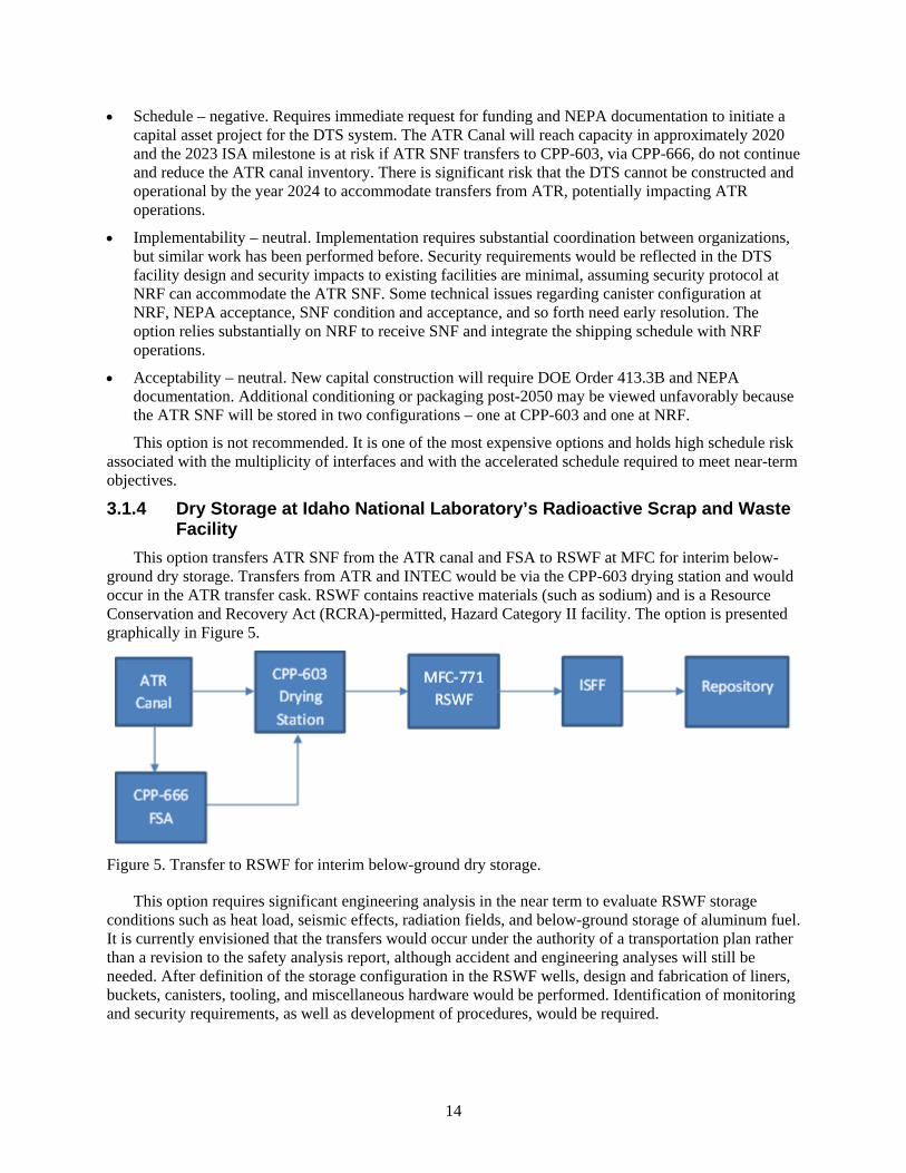
This option transfers ATR SNF from the ATR canal and FSA to RSWF at MFC for interim below-ground dry storage. Transfers from ATR and INTEC would be via the CPP-603 drying station and would occur in the ATR transfer cask. RSWF contains reactive materials (such as sodium) and is a Resource Conservation and Recovery Act (RCRA)-permitted, Hazard Category II facility. The option is presented graphically in Figure 5.
Figure 5. Transfer to RSWF for interim below-ground dry storage.
This option requires significant engineering analysis in the near term to evaluate RSWF storage conditions such as heat load, seismic effects, radiation fields, and below-ground storage of aluminum fuel. It is currently envisioned that the transfers would occur under the authority of a transportation plan rather than a revision to the safety analysis report, although accident and engineering analyses will still be needed. After definition of the storage configuration in the RSWF wells, design and fabrication of liners, buckets, canisters, tooling, and miscellaneous hardware would be performed. Identification of monitoring and security requirements, as well as development of procedures, would be required.
15
The advantages and disadvantages of this option relative to the screening criteria are as follows:
• Cost – neutral. There is immediate need for funding to perform engineering analyses, revise the RCRA permit, perform NEPA analysis, and update the safety basis, which may be substantial. Costs for security upgrades at RSWF may be substantial costs and may require a small capital project. No large capital costs are required until the end of interim storage, at which time capital expenditures to make the ATR SNF “road-ready” are likely, presumably at ISFF.
• Schedule – negative. Development of requirements for storage in RSWF cannot be completed in time to meet the ISA 2023 milestone, considering throughput and concurrent shipping of Experimental Breeder Reactor (EBR)-II SNF. ATR operations would be impacted as the ATR canal reaches capacity. In addition, there is insufficient storage capacity to sustain transfers through the year 2050.
• Implementability – negative. Engineering evaluations are judged to be moderate, but revision of the RCRA permit (requiring state approval) and the potential for NEPA analysis are judged to be high risk. Required changes to security plans, increased security operating costs, and high potential for capital security investments pose significant risks.
• Acceptability – negative. Underground storage of aluminum fuel mixed with storage of sodium (combustible) fuel in a RCRA-permitted area is potentially unacceptable to some stakeholders. The need to update NEPA documentation opens the possibility of external stakeholder intervention, with attendant schedule risk for ISA 2023 compliance.
This option is not recommended. Although use of existing facilities and transfer/transport systems limit the option’s cost, technical uncertainty surrounding corrosion, permitting, safeguards and security, and packaging present high schedule, acceptability, and implementation risks.
3.1.5 Dry Storage of Advanced Test Reactor Spent Nuclear Fuel at the Underground Fuel Storage Facility
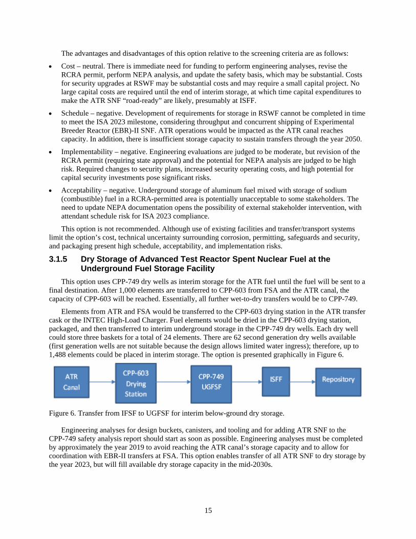
This option uses CPP-749 dry wells as interim storage for the ATR fuel until the fuel will be sent to a final destination. After 1,000 elements are transferred to CPP-603 from FSA and the ATR canal, the capacity of CPP-603 will be reached. Essentially, all further wet-to-dry transfers would be to CPP-749.
Elements from ATR and FSA would be transferred to the CPP-603 drying station in the ATR transfer cask or the INTEC High-Load Charger. Fuel elements would be dried in the CPP-603 drying station, packaged, and then transferred to interim underground storage in the CPP-749 dry wells. Each dry well could store three baskets for a total of 24 elements. There are 62 second generation dry wells available (first generation wells are not suitable because the design allows limited water ingress); therefore, up to 1,488 elements could be placed in interim storage. The option is presented graphically in Figure 6.
Figure 6. Transfer from IFSF to UGFSF for interim below-ground dry storage.
Engineering analyses for design buckets, canisters, and tooling and for adding ATR SNF to the CPP-749 safety analysis report should start as soon as possible. Engineering analyses must be completed by approximately the year 2019 to avoid reaching the ATR canal’s storage capacity and to allow for coordination with EBR-II transfers at FSA. This option enables transfer of all ATR SNF to dry storage by the year 2023, but will fill available dry storage capacity in the mid-2030s.
16
The advantages and disadvantages of this option relative to the screening criteria are as follows:
• Cost – positive. Near-term costs through the year 2023 are for engineering analysis, operations, and maintenance and they reflect use of existing INL capacity. Facility modification, packaging, and tooling costs are relatively minor. No capital projects are required and life-cycle costs are low.
• Schedule – neutral. This option complies with the ISA 2023 milestone, but CPP-749 has insufficient capacity to sustain transfers through the year 2050. There is minimal impact on ATR until the mid-2030s, at which time existing capacity is reached. Large capital investments are deferred until that time.
• Implementability – negative. All technologies and processes are mature and relatively simple. Impact from security requirements is limited and management control remains under DOE Idaho Operations Office purview. Production rates cannot be met after the mid-2030s and underground storage of aluminum-clad fuel presents technical issues with corrosion.
• Acceptability – negative. Near-term actions can be funded and are within DOE’s sphere of influence. Storage of aluminum fuel in underground storage presents environmental safety concerns and the option is not sustainable through the year 2050. This option does not support projected generation rates; in addition, the impact on ATR after capacity is reached is unacceptable.
This option is not recommended. The transfer of Peach Bottom fuel at CPP-749 in order to open space for ATR fuel at IFSF is considered better use of facility capacity. Canister design costs and technical concerns, prevention of ground moisture wetting to the fuel, safety basis changes, extra handling and drying (including logistical challenges for throughput capacity at CPP-603), and the lack of storage precedent for ATR fuel at CPP-749 present significant risks in this option.
3.1.6 Dry Storage of Advanced Test Reactor Spent Nuclear Fuel at the Irradiated Fuel Storage Facility
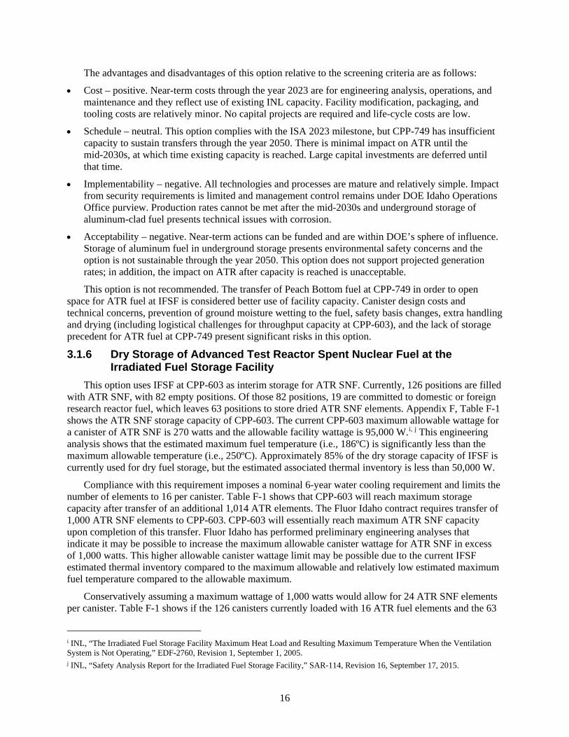
This option uses IFSF at CPP-603 as interim storage for ATR SNF. Currently, 126 positions are filled with ATR SNF, with 82 empty positions. Of those 82 positions, 19 are committed to domestic or foreign research reactor fuel, which leaves 63 positions to store dried ATR SNF elements. Appendix F, Table F-1 shows the ATR SNF storage capacity of CPP-603. The current CPP-603 maximum allowable wattage for a canister of ATR SNF is 270 watts and the allowable facility wattage is 95,000 W.i, j This engineering analysis shows that the estimated maximum fuel temperature (i.e., 186ºC) is significantly less than the maximum allowable temperature (i.e., 250ºC). Approximately 85% of the dry storage capacity of IFSF is currently used for dry fuel storage, but the estimated associated thermal inventory is less than 50,000 W.
Compliance with this requirement imposes a nominal 6-year water cooling requirement and limits the number of elements to 16 per canister. Table F-1 shows that CPP-603 will reach maximum storage capacity after transfer of an additional 1,014 ATR elements. The Fluor Idaho contract requires transfer of 1,000 ATR SNF elements to CPP-603. CPP-603 will essentially reach maximum ATR SNF capacity upon completion of this transfer. Fluor Idaho has performed preliminary engineering analyses that indicate it may be possible to increase the maximum allowable canister wattage for ATR SNF in excess of 1,000 watts. This higher allowable canister wattage limit may be possible due to the current IFSF estimated thermal inventory compared to the maximum allowable and relatively low estimated maximum fuel temperature compared to the allowable maximum.
Conservatively assuming a maximum wattage of 1,000 watts would allow for 24 ATR SNF elements per canister. Table F-1 shows if the 126 canisters currently loaded with 16 ATR fuel elements and the 63
i INL, “The Irradiated Fuel Storage Facility Maximum Heat Load and Resulting Maximum Temperature When the Ventilation System is Not Operating,” EDF-2760, Revision 1, September 1, 2005. j INL, “Safety Analysis Report for the Irradiated Fuel Storage Facility,” SAR-114, Revision 16, September 17, 2015.
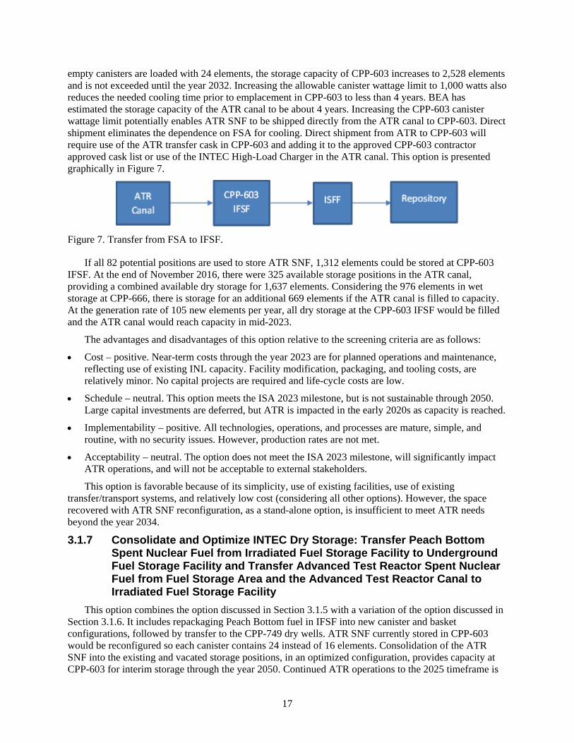
17
empty canisters are loaded with 24 elements, the storage capacity of CPP-603 increases to 2,528 elements and is not exceeded until the year 2032. Increasing the allowable canister wattage limit to 1,000 watts also reduces the needed cooling time prior to emplacement in CPP-603 to less than 4 years. BEA has estimated the storage capacity of the ATR canal to be about 4 years. Increasing the CPP-603 canister wattage limit potentially enables ATR SNF to be shipped directly from the ATR canal to CPP-603. Direct shipment eliminates the dependence on FSA for cooling. Direct shipment from ATR to CPP-603 will require use of the ATR transfer cask in CPP-603 and adding it to the approved CPP-603 contractor approved cask list or use of the INTEC High-Load Charger in the ATR canal. This option is presented graphically in Figure 7.
Figure 7. Transfer from FSA to IFSF.
If all 82 potential positions are used to store ATR SNF, 1,312 elements could be stored at CPP-603 IFSF. At the end of November 2016, there were 325 available storage positions in the ATR canal, providing a combined available dry storage for 1,637 elements. Considering the 976 elements in wet storage at CPP-666, there is storage for an additional 669 elements if the ATR canal is filled to capacity. At the generation rate of 105 new elements per year, all dry storage at the CPP-603 IFSF would be filled and the ATR canal would reach capacity in mid-2023.
The advantages and disadvantages of this option relative to the screening criteria are as follows:
• Cost – positive. Near-term costs through the year 2023 are for planned operations and maintenance, reflecting use of existing INL capacity. Facility modification, packaging, and tooling costs, are relatively minor. No capital projects are required and life-cycle costs are low.
• Schedule – neutral. This option meets the ISA 2023 milestone, but is not sustainable through 2050. Large capital investments are deferred, but ATR is impacted in the early 2020s as capacity is reached.
• Implementability – positive. All technologies, operations, and processes are mature, simple, and routine, with no security issues. However, production rates are not met.
• Acceptability – neutral. The option does not meet the ISA 2023 milestone, will significantly impact ATR operations, and will not be acceptable to external stakeholders.
This option is favorable because of its simplicity, use of existing facilities, use of existing transfer/transport systems, and relatively low cost (considering all other options). However, the space recovered with ATR SNF reconfiguration, as a stand-alone option, is insufficient to meet ATR needs beyond the year 2034.
3.1.7 Consolidate and Optimize INTEC Dry Storage: Transfer Peach Bottom Spent Nuclear Fuel from Irradiated Fuel Storage Facility to Underground Fuel Storage Facility and Transfer Advanced Test Reactor Spent Nuclear Fuel from Fuel Storage Area and the Advanced Test Reactor Canal to Irradiated Fuel Storage Facility
This option combines the option discussed in Section 3.1.5 with a variation of the option discussed in Section 3.1.6. It includes repackaging Peach Bottom fuel in IFSF into new canister and basket configurations, followed by transfer to the CPP-749 dry wells. ATR SNF currently stored in CPP-603 would be reconfigured so each canister contains 24 instead of 16 elements. Consolidation of the ATR SNF into the existing and vacated storage positions, in an optimized configuration, provides capacity at CPP-603 for interim storage through the year 2050. Continued ATR operations to the 2025 timeframe is

18
possible under this option without transfer of Peach Bottom fuel to CPP-749 through reconfiguration of ATR fuel currently in CPP-603 and direct transfer from the ATR canal to CPP-603. The option is presented graphically in Figure 8.
Figure 8. Consolidation and optimization of IFSF and UGFSF for interim storage.
Engineering and security evaluations to increase the number of elements in CPP-603 storage positions (from 16 to 24) would be required for optimization. Preliminary investigation indicates this is feasible. Storage of the Peach Bottom fuel in CPP-749 would be limited to second generation wells, because the first wells are susceptible to water ingress with attendant increased risk of corrosion. Alternately, direct transfer of ATR SNF to the CPP-603 drying facility would require addition of the ATR transfer cask to the CPP-603 cask list or evaluation and use of the INTEC High-Load Charger in the ATR canal.
The advantages and disadvantages of this option relative to the screening criteria are as follows:
• Cost – positive. Near-term costs through the year 2023 are for engineering analysis, operations, and maintenance, reflecting use of existing INL capacity. Facility modification, packaging, and tooling costs are relatively minor. No capital projects are required and life-cycle costs are low.
• Schedule – positive. The ISA 2023 milestone can be met and the option is sustainable through 2050 without large capital investment. Negligible impact on ATR.
• Implementability – positive. Technologies and methods are mature and reasonably simple. There is minimal risk in adverse outcomes from the evaluations and there are relatively few security implications.
• Acceptability – positive. Complies with ISA and is sustainable through the year 2050. Supports the long-term mission without impact on ATR and supports annual generation rates. This option scored positively in all four consolidated criteria because of its simplicity, use of existing
facilities, use of existing transfer/transport systems, and relatively low cost. This combination of fuel consolidations will meet the projected ATR SNF dry storage needs through the year 2050.
3.1.8 Dry Storage at the Advanced Test Reactor using Commercially Available Systems
This option provides ATR SNF transfer and commercial dry storage capabilities for ATR SNF at the ATR Complex. Construction of new infrastructure for transfers and for the dry storage capability would be a line item capital acquisition, although the facilities would likely be physically separate. An Environmental Impact Statement (EIS) would be required per NEPA. NEPA analysis, design, construction, and startup are anticipated to take approximately 5 to 7 years once funding is available. Once the new facility is operational, commercial storage could be sustained through the year 2050. ATR SNF would be transferred from the ATR canal directly to the new DTS. The option is presented graphically in Figure 9.
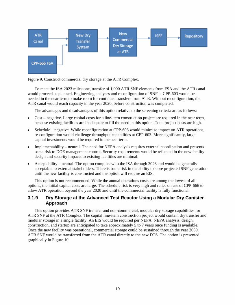
19
Figure 9. Construct commercial dry storage at the ATR Complex.
To meet the ISA 2023 milestone, transfer of 1,000 ATR SNF elements from FSA and the ATR canal would proceed as planned. Engineering analyses and reconfiguration of SNF at CPP-603 would be needed in the near term to make room for continued transfers from ATR. Without reconfiguration, the ATR canal would reach capacity in the year 2020, before construction was completed.
The advantages and disadvantages of this option relative to the screening criteria are as follows:
• Cost – negative. Large capital costs for a line-item construction project are required in the near term, because existing facilities are inadequate to fill the need in this option. Total project costs are high.
• Schedule – negative. While reconfiguration at CPP-603 would minimize impact on ATR operations, re-configuration would challenge throughput capabilities at CPP-603. More significantly, large capital investments would be required in the near term.
• Implementability – neutral. The need for NEPA analysis requires external coordination and presents some risk to DOE management control. Security requirements would be reflected in the new facility design and security impacts to existing facilities are minimal.
• Acceptability – neutral. The option complies with the ISA through 2023 and would be generally acceptable to external stakeholders. There is some risk in the ability to store projected SNF generation until the new facility is constructed and the option will require an EIS. This option is not recommended. While the annual operations costs are among the lowest of all
options, the initial capital costs are large. The schedule risk is very high and relies on use of CPP-666 to allow ATR operation beyond the year 2020 and until the commercial facility is fully functional.
3.1.9 Dry Storage at the Advanced Test Reactor Using a Modular Dry Canister Approach
This option provides ATR SNF transfer and non-commercial, modular dry storage capabilities for ATR SNF at the ATR Complex. The capital line-item construction project would contain dry transfer and modular storage in a single facility. An EIS would be required per NEPA. NEPA analysis, design, construction, and startup are anticipated to take approximately 5 to 7 years once funding is available. Once the new facility was operational, commercial storage could be sustained through the year 2050. ATR SNF would be transferred from the ATR canal directly to the new DTS. The option is presented graphically in Figure 10.
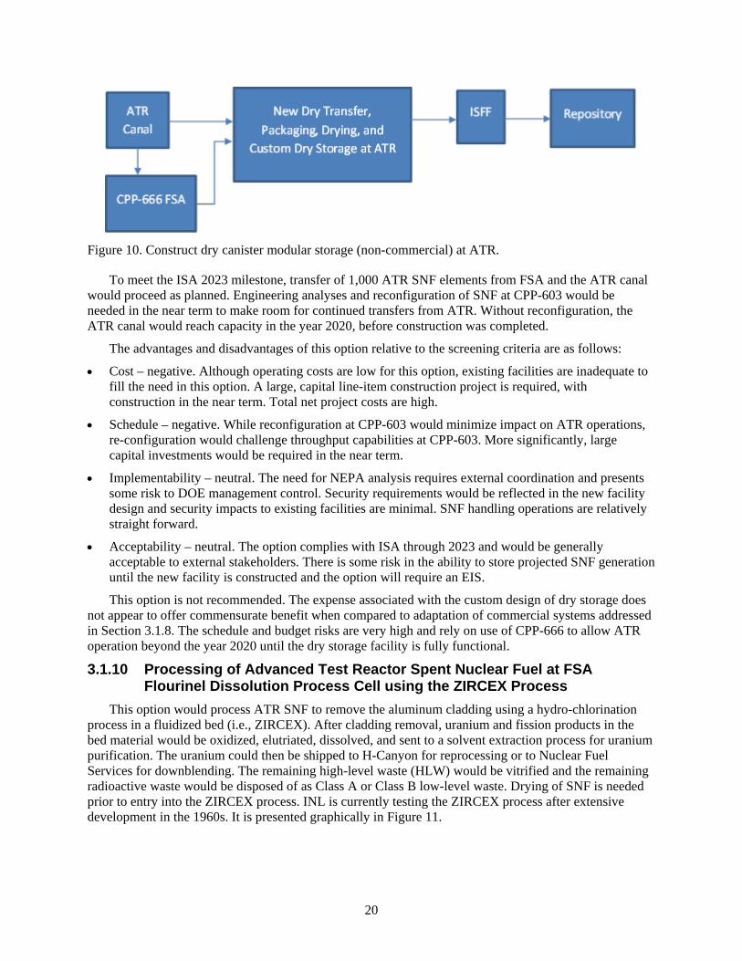
20
Figure 10. Construct dry canister modular storage (non-commercial) at ATR.
To meet the ISA 2023 milestone, transfer of 1,000 ATR SNF elements from FSA and the ATR canal would proceed as planned. Engineering analyses and reconfiguration of SNF at CPP-603 would be needed in the near term to make room for continued transfers from ATR. Without reconfiguration, the ATR canal would reach capacity in the year 2020, before construction was completed.
The advantages and disadvantages of this option relative to the screening criteria are as follows:
• Cost – negative. Although operating costs are low for this option, existing facilities are inadequate to fill the need in this option. A large, capital line-item construction project is required, with construction in the near term. Total net project costs are high.
• Schedule – negative. While reconfiguration at CPP-603 would minimize impact on ATR operations, re-configuration would challenge throughput capabilities at CPP-603. More significantly, large capital investments would be required in the near term.
• Implementability – neutral. The need for NEPA analysis requires external coordination and presents some risk to DOE management control. Security requirements would be reflected in the new facility design and security impacts to existing facilities are minimal. SNF handling operations are relatively straight forward.
• Acceptability – neutral. The option complies with ISA through 2023 and would be generally acceptable to external stakeholders. There is some risk in the ability to store projected SNF generation until the new facility is constructed and the option will require an EIS. This option is not recommended. The expense associated with the custom design of dry storage does
not appear to offer commensurate benefit when compared to adaptation of commercial systems addressed in Section 3.1.8. The schedule and budget risks are very high and rely on use of CPP-666 to allow ATR operation beyond the year 2020 until the dry storage facility is fully functional.
3.1.10 Processing of Advanced Test Reactor Spent Nuclear Fuel at FSA Flourinel Dissolution Process Cell using the ZIRCEX Process
This option would process ATR SNF to remove the aluminum cladding using a hydro-chlorination process in a fluidized bed (i.e., ZIRCEX). After cladding removal, uranium and fission products in the bed material would be oxidized, elutriated, dissolved, and sent to a solvent extraction process for uranium purification. The uranium could then be shipped to H-Canyon for reprocessing or to Nuclear Fuel Services for downblending. The remaining high-level waste (HLW) would be vitrified and the remaining radioactive waste would be disposed of as Class A or Class B low-level waste. Drying of SNF is needed prior to entry into the ZIRCEX process. INL is currently testing the ZIRCEX process after extensive development in the 1960s. It is presented graphically in Figure 11.
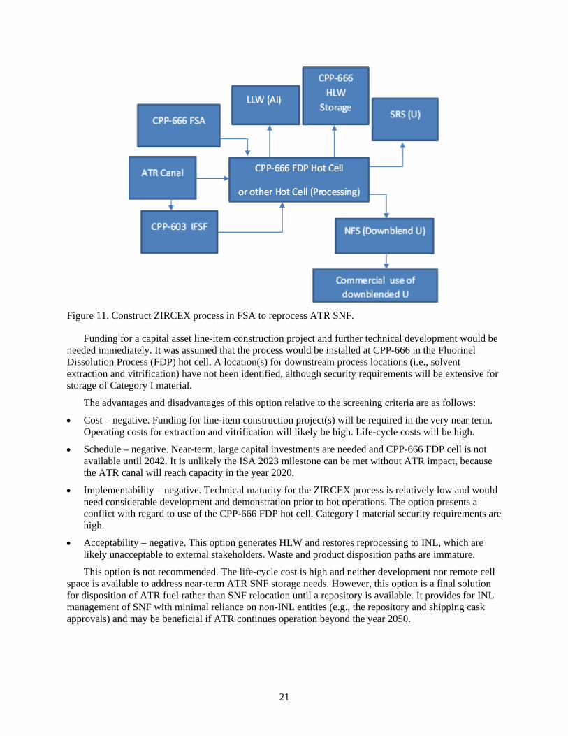
21
Figure 11. Construct ZIRCEX process in FSA to reprocess ATR SNF.
Funding for a capital asset line-item construction project and further technical development would be needed immediately. It was assumed that the process would be installed at CPP-666 in the Fluorinel Dissolution Process (FDP) hot cell. A location(s) for downstream process locations (i.e., solvent extraction and vitrification) have not been identified, although security requirements will be extensive for storage of Category I material.
The advantages and disadvantages of this option relative to the screening criteria are as follows:
• Cost – negative. Funding for line-item construction project(s) will be required in the very near term. Operating costs for extraction and vitrification will likely be high. Life-cycle costs will be high.
• Schedule – negative. Near-term, large capital investments are needed and CPP-666 FDP cell is not available until 2042. It is unlikely the ISA 2023 milestone can be met without ATR impact, because the ATR canal will reach capacity in the year 2020.
• Implementability – negative. Technical maturity for the ZIRCEX process is relatively low and would need considerable development and demonstration prior to hot operations. The option presents a conflict with regard to use of the CPP-666 FDP hot cell. Category I material security requirements are high.
• Acceptability – negative. This option generates HLW and restores reprocessing to INL, which are likely unacceptable to external stakeholders. Waste and product disposition paths are immature.
This option is not recommended. The life-cycle cost is high and neither development nor remote cell space is available to address near-term ATR SNF storage needs. However, this option is a final solution for disposition of ATR fuel rather than SNF relocation until a repository is available. It provides for INL management of SNF with minimal reliance on non-INL entities (e.g., the repository and shipping cask approvals) and may be beneficial if ATR continues operation beyond the year 2050.
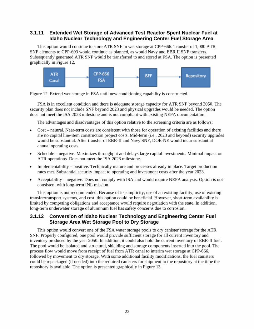
22
3.1.11 Extended Wet Storage of Advanced Test Reactor Spent Nuclear Fuel at Idaho Nuclear Technology and Engineering Center Fuel Storage Area
This option would continue to store ATR SNF in wet storage at CPP-666. Transfer of 1,000 ATR SNF elements to CPP-603 would continue as planned, as would Navy and EBR II SNF transfers. Subsequently generated ATR SNF would be transferred to and stored at FSA. The option is presented graphically in Figure 12.
Figure 12. Extend wet storage in FSA until new conditioning capability is constructed.
FSA is in excellent condition and there is adequate storage capacity for ATR SNF beyond 2050. The security plan does not include SNF beyond 2023 and physical upgrades would be needed. The option does not meet the ISA 2023 milestone and is not compliant with existing NEPA documentation.
The advantages and disadvantages of this option relative to the screening criteria are as follows:
• Cost – neutral. Near-term costs are consistent with those for operation of existing facilities and there are no capital line-item construction project costs. Mid-term (i.e., 2023 and beyond) security upgrades would be substantial. After transfer of EBR-II and Navy SNF, DOE-NE would incur substantial annual operating costs.
• Schedule – negative. Maximizes throughput and delays large capital investments. Minimal impact on ATR operations. Does not meet the ISA 2023 milestone.
• Implementability – positive. Technically mature and processes already in place. Target production rates met. Substantial security impact to operating and investment costs after the year 2023.
• Acceptability – negative. Does not comply with ISA and would require NEPA analysis. Option is not consistent with long-term INL mission.
This option is not recommended. Because of its simplicity, use of an existing facility, use of existing transfer/transport systems, and cost, this option could be beneficial. However, short-term availability is limited by competing obligations and acceptance would require negotiation with the state. In addition, long-term underwater storage of aluminum fuel has safety concerns due to corrosion.
3.1.12 Conversion of Idaho Nuclear Technology and Engineering Center Fuel Storage Area Wet Storage Pool to Dry Storage
This option would convert one of the FSA water storage pools to dry canister storage for the ATR SNF. Properly configured, one pool would provide sufficient storage for all current inventory and inventory produced by the year 2050. In addition, it could also hold the current inventory of EBR-II fuel. The pool would be isolated and structural, shielding and storage components inserted into the pool. The process flow would move from receipt of fuel from ATR canal to interim wet storage at CPP-666, followed by movement to dry storage. With some additional facility modifications, the fuel canisters could be repackaged (if needed) into the required canisters for shipment to the repository at the time the repository is available. The option is presented graphically in Figure 13.
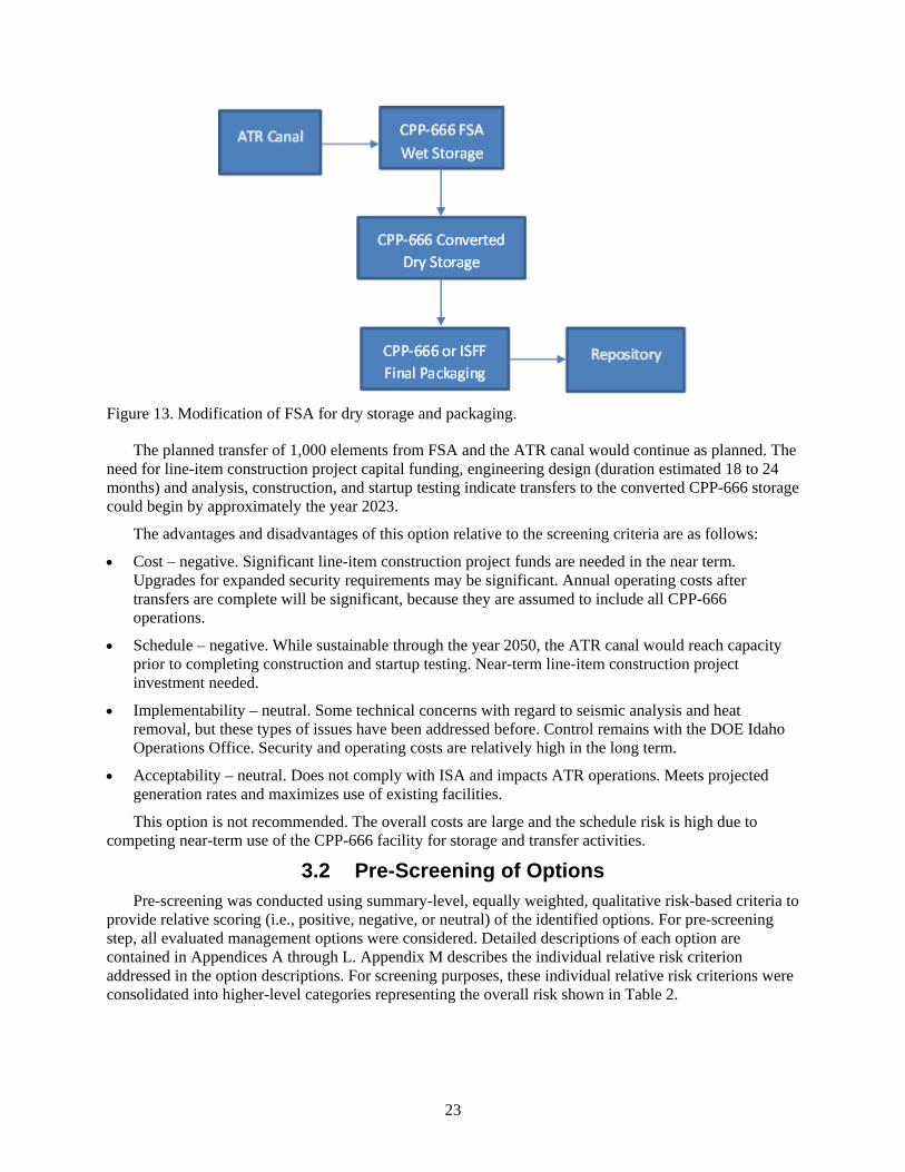
23
Figure 13. Modification of FSA for dry storage and packaging.
The planned transfer of 1,000 elements from FSA and the ATR canal would continue as planned. The need for line-item construction project capital funding, engineering design (duration estimated 18 to 24 months) and analysis, construction, and startup testing indicate transfers to the converted CPP-666 storage could begin by approximately the year 2023.
The advantages and disadvantages of this option relative to the screening criteria are as follows:
• Cost – negative. Significant line-item construction project funds are needed in the near term. Upgrades for expanded security requirements may be significant. Annual operating costs after transfers are complete will be significant, because they are assumed to include all CPP-666 operations.
• Schedule – negative. While sustainable through the year 2050, the ATR canal would reach capacity prior to completing construction and startup testing. Near-term line-item construction project investment needed.
• Implementability – neutral. Some technical concerns with regard to seismic analysis and heat removal, but these types of issues have been addressed before. Control remains with the DOE Idaho Operations Office. Security and operating costs are relatively high in the long term.
• Acceptability – neutral. Does not comply with ISA and impacts ATR operations. Meets projected generation rates and maximizes use of existing facilities.
This option is not recommended. The overall costs are large and the schedule risk is high due to competing near-term use of the CPP-666 facility for storage and transfer activities.
3.2 Pre-Screening of Options Pre-screening was conducted using summary-level, equally weighted, qualitative risk-based criteria to
provide relative scoring (i.e., positive, negative, or neutral) of the identified options. For pre-screening step, all evaluated management options were considered. Detailed descriptions of each option are contained in Appendices A through L. Appendix M describes the individual relative risk criterion addressed in the option descriptions. For screening purposes, these individual relative risk criterions were consolidated into higher-level categories representing the overall risk shown in Table 2.
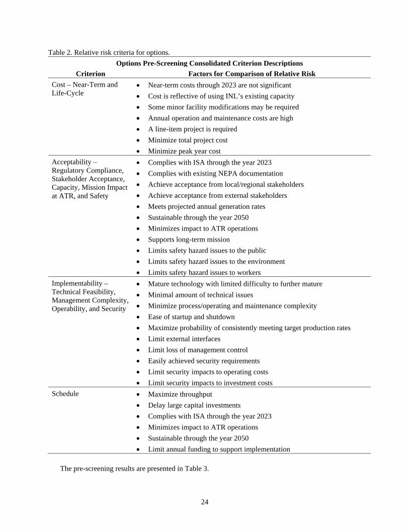
24
Table 2. Relative risk criteria for options. Options Pre-Screening Consolidated Criterion Descriptions
Criterion Factors for Comparison of Relative Risk Cost – Near-Term and Life-Cycle
• Near-term costs through 2023 are not significant • Cost is reflective of using INL’s existing capacity • Some minor facility modifications may be required • Annual operation and maintenance costs are high • A line-item project is required • Minimize total project cost • Minimize peak year cost
Acceptability – Regulatory Compliance, Stakeholder Acceptance, Capacity, Mission Impact at ATR, and Safety
• Complies with ISA through the year 2023 • Complies with existing NEPA documentation • Achieve acceptance from local/regional stakeholders • Achieve acceptance from external stakeholders • Meets projected annual generation rates • Sustainable through the year 2050 • Minimizes impact to ATR operations • Supports long-term mission • Limits safety hazard issues to the public • Limits safety hazard issues to the environment • Limits safety hazard issues to workers
Implementability – Technical Feasibility, Management Complexity, Operability, and Security
• Mature technology with limited difficulty to further mature • Minimal amount of technical issues • Minimize process/operating and maintenance complexity • Ease of startup and shutdown • Maximize probability of consistently meeting target production rates • Limit external interfaces • Limit loss of management control • Easily achieved security requirements • Limit security impacts to operating costs • Limit security impacts to investment costs
Schedule • Maximize throughput • Delay large capital investments • Complies with ISA through the year 2023 • Minimizes impact to ATR operations • Sustainable through the year 2050 • Limit annual funding to support implementation
The pre-screening results are presented in Table 3.
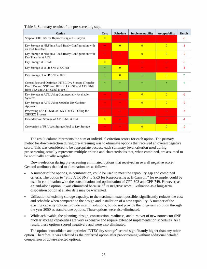
25
Table 3. Summary results of the pre-screening step.
Option Cost Schedule Implementability Acceptability Result Ship to DOE SRS for Reprocessing at H-Canyon 0 ─ ─ ─ -3
Dry Storage at NRF in a Road-Ready Configuration with an FSA Interface
─ 0 0 0 -1
Dry Storage at NRF in a Road-Ready Configuration with Dry Transfer at ATR
─ ─ 0 0 -2
Dry Storage at RSWF 0 ─ ─ ─ -3
Dry Storage of ATR SNF at UGFSF + 0 ─ ─ -1
Dry Storage of ATR SNF at IFSF + 0 + 0 2
Consolidate and Optimize INTEC Dry Storage (Transfer Peach Bottom SNF from IFSF to UGFSF and ATR SNF from FSA and ATR Canal to IFSF)
+ + + + 4
Dry Storage at ATR Using Commercially Available Systems
─ ─ 0 0 -2
Dry Storage at ATR Using Modular Dry Canister Approach
─ ─ 0 0 -2
Processing of ATR SNF at FSA FDP Cell Using the ZIRCEX Process
─ ─ ─ ─ -4
Extended Wet Storage of ATR SNF at FSA 0 ─ + ─ -1
Conversion of FSA Wet Storage Pool to Dry Storage ─ ─ 0 0 -2
The result column represents the sum of individual criterion scores for each option. The primary
metric for down-selection during pre-screening was to eliminate options that received an overall negative score. This was considered to be appropriate because each summary-level criterion used during pre-screening actually represents multiple criteria and characteristics that, when combined, are assumed to be nominally equally weighted.
Down-selection during pre-screening eliminated options that received an overall negative score. General attributes that led to elimination are as follows:
• A number of the options, in combination, could be used to meet the capability gap and combined criteria. The option to “Ship ATR SNF to SRS for Reprocessing at H-Canyon,” for example, could be used in combination with the consolidation and optimization of CPP-603 and CPP-749. However, as a stand-alone option, it was eliminated because of its negative score. Evaluation as a long-term disposition option at a later date may be warranted.
• Utilization of existing storage capacity, to the maximum extent possible, significantly reduces the cost and schedule when compared to the design and installation of a new capability. A number of the existing capacity options provide interim solutions, but do not provide the long-term solution through the year 2050 as stand-alone options. These options were also eliminated.
• While achievable, the planning, design, construction, readiness, and turnover of new nonreactor SNF nuclear storage capabilities are very expensive and require extended implementation schedules. As a result, these options scored negatively and were also eliminated.
The option “consolidate and optimize INTEC dry storage” scored significantly higher than any other option. Therefore, it was selected as the preferred option after pre-screening without additional detailed comparison of down-selected options.
26
4. SPENT NUCLEAR FUEL MANAGEMENT OPTIONS ANALYSIS – EVALUATIONS
This section presents an evaluation of the preferred option for management of ATR SNF. The preferred option is consolidation and optimization of ATR SNF, using CPP-603 and CPP-749 for dry storage. Peach Bottom SNF from CPP-603 IFSF would be transferred to the CPP-749 dry wells as interim storage. Optimizing the ATR SNF storage configuration at CPP-603 will increase capacity and transfer of ATR SNF from FSA or ATR to CPP-603 could continue until the year 2050.
Long-term solutions rely on opening a repository, the repository’s acceptance criteria, and national priorities for shipping schedules. Other actions that enhance storage in CPP-603 and CPP-749 are included in the recommended strategy.
4.1 Detailed Analysis of Selected Option – Consolidation and Optimization of CPP-603 and CPP-749
Activities identified in the preferred option can be initiated in 2017 and would need to be completed in 2025. This allows for completion of ATR SNF transfers under the Fluor Idaho contract, EBR-II transfers, and Navy SNF transfers and enables implementation of the selected option. Throughput capabilities limit concurrent performance of these planned transfers with the recommended consolidation and transfers at CPP-603 and CPP-749. Criticality, security, and engineering analyses should be performed first to enable reconfiguration of ATR fuel currently stored in IFSF.
CPP-603 storage capacity can be optimized by increasing the number of ATR SNF elements in each storage position from 16 to 24. Consolidation of the 1,000 ATR SNF elements, currently planned for wet-to-dry transfer, is part of this recommended option. Preliminary criticality, thermal, and security evaluations indicate this is feasible.
Additional space in CPP-603 can be made available by transferring the Peach Bottom SNF, currently stored at CPP-603, to dry underground storage at CPP-749 to make more room. Peach Bottom SNF is currently stored in 71 positions at CPP-603, with 12 elements per position. During transfer to CPP-749, the Peach Bottom SNF would be reconfigured to contain 18 elements in a canister, filling 48 of the available positions in CPP-749. Preliminary criticality and security evaluations indicate this is feasible. Transfer of Peach Bottom fuel can be delayed from mid to late 2020 without any significant impact on ATR operations. Required engineering analyses and fabrication of needed components can also be delayed.
This option provides for low-cost, compliant storage potentially through the year 2050. Table G-1 in Appendix G shows that CPP-603 storage capacity is exceeded in the year 2049. However, the table does not take into account ATR core internal changeout, which should occur at least three times during the time period from 2020 to 2050. During core internal changeout, ATR is down for at least 8 months; therefore, the ATR fuel generation rate shown in Table G-1 is very conservative. This recommended option maintains the flexibility to respond to changing conditions as risks and opportunities evolve over the next several decades.
4.1.1 Strategies and Assumptions The overall strategy of this option is to prepare for optimization and consolidation in the near term,
while CPP-666 is emptied of EBR-II, Navy, and current ATR SNF inventory. Limited by facility throughput, the majority of these transfers are expected to finish by the year 2019. Personnel, operations, and facility resources can then be applied to activities for supporting direct shipment of ATR fuel from the ATR canal to CPP-603 and additional activities needed to support full implantation of the option. Direct shipment of ATR fuel from the ATR canal will be required in late 2019 or earlier to avoid impact to ATR operations and to ensure compliance with the 2023 ISA milestone. At expected generation rates,
27
the ATR canal will fill to capacity during the year 2020. A sequence of transfers should be included in the near-term planning to avoid impact on ATR while optimizing the efficiency of transfers and repackaging at CPP-603 and CPP-666. Preparatory work that must be completed prior to optimization and consolidation includes the following:
• Perform criticality and security analyses to confirm and document preliminary evaluations.
• Perform CPP-603 thermal loading analyses to confirm and document preliminary increased canister wattage limits.
• Revise and update NEPA documentation.
• Design, fabricate, and demonstrate prototypical buckets and canisters.
• Fabricate buckets and canisters.
• Design, fabricate, and demonstrate prototypical fuel-handling tools.
• Fabricate fuel-handling tools.
• Analyze ATR transfer cask and High-Load Charger for direct transfers from ATR to CPP-603.
• Update applicable contractor-approved cask lists, contractor-approved fuels lists, and criticality safety controls list to include the ATR transfer cask or INTEC High Load Charger, as appropriate.
• Develop corrosion control and hydrogen monitoring programs for storage of Peach Bottom SNF in CPP-749 Generation II vaults.
• Develop and demonstrate fuel-handling procedures.
• Perform readiness assessments.
Completion of these tasks will enable the optimization and consolidation to begin in 2019 or as soon as the other transfers are completed. Identification of the tasks was based on the following assumptions:
• The Peach Bottom cask will be used to top load Peach Bottom fuel at CPP-603 IFSF and bottom unload at CPP-749.
• Cask transfers to CPP-749 are weather dependent and will be limited to approximately 8 months per year.
• New handling tools and basket and bucket designs for Peach Bottom SNF can be added to relevant contractor-approved fuels lists and will not impact the safety basis.
• Revisions and updates to NEPA documentation are limited to an environmental checklist and categorical exclusion.
• Changes to maintain vault dryness to prevent corrosion or hydrogen generation may include addition of high-efficiency particulate air filtration on the vent line and development of a corrosion monitoring program, as well as reliance on the Peach Bottom canister to keep Peach Bottom SNF dry.
• A detailed assessment of readiness would be required for two INTEC facilities (i.e., CPP-749 and CPP-603), possibly for ATR, and for cask transfer operations. This includes performing full-scale dry runs and proficiency operations.
4.1.2 Cost Rough-order-of-magnitude costs for this option are comparatively low, but depend heavily on
parametric and analogous estimates. Further, the scope has not been completely defined. While the option can be executed without a capital line-item construction project and uses existing facility capabilities, total cost cannot be accurately estimated without additional definition. Significant portions of the scope will be associated with risk mitigation and opportunities that maintain flexibility for longer-term
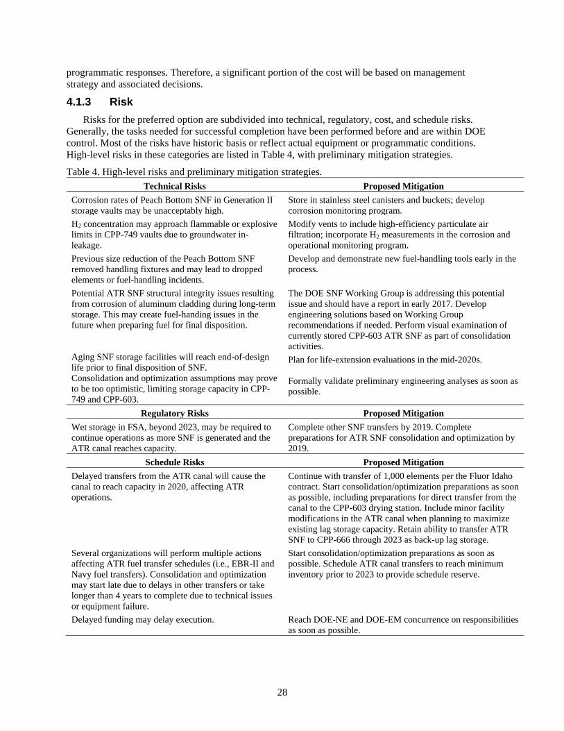
28
programmatic responses. Therefore, a significant portion of the cost will be based on management strategy and associated decisions.
4.1.3 Risk Risks for the preferred option are subdivided into technical, regulatory, cost, and schedule risks.
Generally, the tasks needed for successful completion have been performed before and are within DOE control. Most of the risks have historic basis or reflect actual equipment or programmatic conditions. High-level risks in these categories are listed in Table 4, with preliminary mitigation strategies.
Table 4. High-level risks and preliminary mitigation strategies. Technical Risks Proposed Mitigation
Corrosion rates of Peach Bottom SNF in Generation II storage vaults may be unacceptably high.
Store in stainless steel canisters and buckets; develop corrosion monitoring program.
H2 concentration may approach flammable or explosive limits in CPP-749 vaults due to groundwater in-leakage.
Modify vents to include high-efficiency particulate air filtration; incorporate H2 measurements in the corrosion and operational monitoring program.
Previous size reduction of the Peach Bottom SNF removed handling fixtures and may lead to dropped elements or fuel-handling incidents.
Develop and demonstrate new fuel-handling tools early in the process.
Potential ATR SNF structural integrity issues resulting from corrosion of aluminum cladding during long-term storage. This may create fuel-handing issues in the future when preparing fuel for final disposition.
The DOE SNF Working Group is addressing this potential issue and should have a report in early 2017. Develop engineering solutions based on Working Group recommendations if needed. Perform visual examination of currently stored CPP-603 ATR SNF as part of consolidation activities.
Aging SNF storage facilities will reach end-of-design life prior to final disposition of SNF.
Plan for life-extension evaluations in the mid-2020s.
Consolidation and optimization assumptions may prove to be too optimistic, limiting storage capacity in CPP-749 and CPP-603.
Formally validate preliminary engineering analyses as soon as possible.
Regulatory Risks Proposed Mitigation Wet storage in FSA, beyond 2023, may be required to continue operations as more SNF is generated and the ATR canal reaches capacity.
Complete other SNF transfers by 2019. Complete preparations for ATR SNF consolidation and optimization by 2019.
Schedule Risks Proposed Mitigation Delayed transfers from the ATR canal will cause the canal to reach capacity in 2020, affecting ATR operations.
Continue with transfer of 1,000 elements per the Fluor Idaho contract. Start consolidation/optimization preparations as soon as possible, including preparations for direct transfer from the canal to the CPP-603 drying station. Include minor facility modifications in the ATR canal when planning to maximize existing lag storage capacity. Retain ability to transfer ATR SNF to CPP-666 through 2023 as back-up lag storage.
Several organizations will perform multiple actions affecting ATR fuel transfer schedules (i.e., EBR-II and Navy fuel transfers). Consolidation and optimization may start late due to delays in other transfers or take longer than 4 years to complete due to technical issues or equipment failure.
Start consolidation/optimization preparations as soon as possible. Schedule ATR canal transfers to reach minimum inventory prior to 2023 to provide schedule reserve.
Delayed funding may delay execution. Reach DOE-NE and DOE-EM concurrence on responsibilities as soon as possible.

29
Cost Risks Proposed Mitigation Assumption of operational costs for FSA, after 2023, will increase costs beyond the budget.
Assign high priority for transfers from FSA and plan sufficient schedule reserve to accommodate equipment failures and delays in other programs.
Security upgrades for FSA, after 2023, will increase costs beyond the budget.
Assign high priority for transfers from FSA and plan sufficient schedule reserve to accommodate equipment failures and delays in other programs.
4.1.4 Complexity Engineering and operations for this option are similar to multiple fuel transfer campaigns that have
been successfully completed in the past. Technically, the option is not highly complex; however, it requires several interfaces and agreements between DOE-NE and DOE-EM that have not been in place in the past. Other SNF transfers must be coordinated with the ATR SNF moves and the throughput of aging facilities must be factored into planning.
4.1.5 Stakeholder Values This option uses existing facilities and systems to improve the safety and compliance of ATR SNF
storage. Large capital expenditures are deferred, avoiding sunk costs that might not support final disposition of the SNF. This approach is consistent with the values of all stakeholders, to the extent that those values have been identified.
4.1.6 Regulatory Compliance Implementation will require some modification of the environmental permits and adherence to NEPA
requirements. These activities are expected to be relatively minor and will not pose undue burden on execution. For example, an environmental checklist will be required, but it is expected to result in a categorical exclusion.
This option relies on interpretation of ISA that retention of fuel in the ATR canal for cooling meet the proposed new CPP-603 canister limit (approximately 30 watts/element) is an adequate technical justification for compliance and that alternatives for cooling are infeasible. With this interpretation, the option is compliant with the ISA requirement to remove SNF from wet storage by 2023. All other options rely on this interpretation as well.
4.1.7 Strategy The overall strategy of this option is to advance long-term management of ATR SNF by providing
compliant, safe dry storage not incurring large costs, maintaining flexibility in the mid and long term, and not relying on entities outside of INL for long-term management of ATR SNF.
In the near term, several actions will enable compliance with the ISA milestone to remove all fuel from wet storage. These actions complete the prerequisites for transfers and address many of the risks identified in Section 4.1.3 for this option:
• Close coordination with other programs and fuel transfer campaigns.
• Early and thorough preparation for ATR and Peach Bottom SNF repackaging and transfer.
When completed, the ATR SNF will be in safe, compliant dry storage.
For the mid-term, this condition preserves DOE-NE’s flexibility to select a disposition strategy that is consistent with repository decisions, schedule, and acceptance criteria and priorities. Sunk costs are avoided.

30
Long-term (i.e., beyond 2050) strategies will depend on evolution of the repository and status of ATR, but this option maintains the flexibility to develop long-term strategies at the appropriate time. Options considered in this study, such as transfer to SRS H-Canyon for processing with ZIRCEX or the AREVA La Hague option, could be combined with the preferred option to support final disposition of the SNF. Many of these disposition options would include construction of ISFF. Those long-term strategies should be developed when more data are available.
5. SUMMARY AND RECOMMENDATIONS ATR operations are anticipated until the year 2050 and are expected to generate more than 3,300
additional SNF elements that require management until a repository is opened or an alternative disposition path is available. Management of existing and newly generated SNF must comply with ISA. The current management approach and associated facilities are not capable of accommodating this additional amount of ATR SNF. This study was undertaken to identify and analyze options needed to address the gap created by this situation.
The study identified 12 options that (either combined or individually) are capable of providing the needed management capability. The options broadly ranged from processing the SNF, placing the SNF in road-ready dry sealed storage, non-road-ready dry sealed storage, and non-road-ready dry storage. Each of the options has some elements of risk and potential technical issues that must be addressed to ensure safe long-term storage. The options were evaluated and screened against four-risk based criteria to select a preferred option.
Based on the results of the screening process, the preferred option is “dry storage at INTEC via consolidation and optimization of IFSF and UGFSF existing capacity.” This option has many benefits that include the following: (1) supports compliance with ISA to remove all SNF from wet storage by December 31, 2023; (2) supports ATR operation to at least the year 2050; (3) optimizes utilization of existing infrastructure; (4) is not reliant on infrastructure and capabilities external to INL; (5) no impact or minimal impact to ATR operations; (6) consolidates storage of INL SNF not destined for onsite treatment; (7) minimizes near and long-term cost and avoids capital asset investment; and (8) least amount of overall risk.
As with all dry storage options, there are potential concerns about the future structural integrity of fuel elements due to the potential for cladding degradation that may impact future handling in support of final packaging and disposition. This concern has many factors associated with it and the DOE SNF Working Group is studying technical issues associated with long-term (i.e., greater than 50-year storage) of aluminum-clad SNF. The current CPP-603 ISFS safety analysis report and the analyses in support of the DOE standard spent fuel canisterk indicate no significant technical issues associated with corrosion and resulting fuel element structural integrity for controlled storage up to 50 years. The SNF Working Group is reviewing all documents associated with CPP-603 and the DOE standardized spent fuel canister, as well as other national laboratory studies and other pertinent studies as a basis for its report. The SNF Working Group should have a report issued in early 2017. Results from this study can be incorporated during planning of the preferred option and ensure needed mitigating actions are implemented as appropriate. Overall risk associated with the preferred option is easily manageable for many reasons. The fundamental basis for the preferred option is the ability to increase CPP-603 ISFS canister wattage limits and fuel element loading. The wattage limit assumed in this report is very conservative compared with the anticipated allowable limit, which is supported by the current facility thermal inventory and estimated maximum fuel temperature. Risk associated with reliance on the ATR canal for mandatory cooling can, in the near term (i.e., up to approximately the year 2022) can be mitigated by having CPP-666 FSA as a back-up if needed. Additional ATR canal storage capacity can be developed through canal clean-up and more diligent management of no longer needed irradiated fuel elements. It is anticipated that ATR Canal
k Material Interactions on Container Integrity During Storage and Transport, DOE/SNF/REP-104, Revision 0, December 2007.

31
operations management will have approximately 2 years to prepare for handling the High-Load Charger; if there are issues, the temporary option of using the ATR cask for shipment to CPP-666 for transfer into the High-Load Charger for transfer to CPP-603 IFSF should be available.
It is recommended that the DOE Idaho Operations Office provide direction to BEA and Fluor Idaho to complete detailed planning, including cost, schedule, needed engineering analyses, and other activities necessary to implement the preferred option.

32
33
Appendix A
Option 1: Ship to the Savannah River Site for Reprocessing in H-Canyon

34
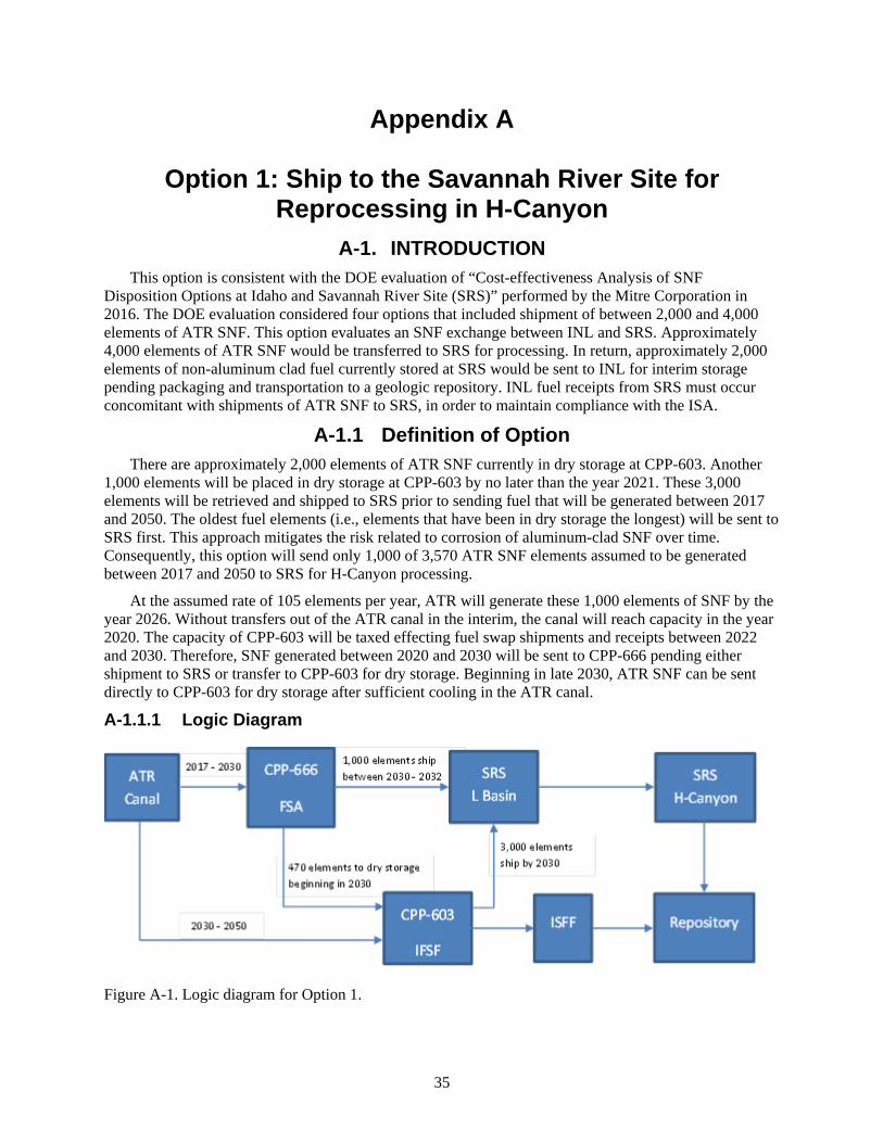
35
Appendix A
Option 1: Ship to the Savannah River Site for Reprocessing in H-Canyon
A-1. INTRODUCTION This option is consistent with the DOE evaluation of “Cost-effectiveness Analysis of SNF
Disposition Options at Idaho and Savannah River Site (SRS)” performed by the Mitre Corporation in 2016. The DOE evaluation considered four options that included shipment of between 2,000 and 4,000 elements of ATR SNF. This option evaluates an SNF exchange between INL and SRS. Approximately 4,000 elements of ATR SNF would be transferred to SRS for processing. In return, approximately 2,000 elements of non-aluminum clad fuel currently stored at SRS would be sent to INL for interim storage pending packaging and transportation to a geologic repository. INL fuel receipts from SRS must occur concomitant with shipments of ATR SNF to SRS, in order to maintain compliance with the ISA.
A-1.1 Definition of Option There are approximately 2,000 elements of ATR SNF currently in dry storage at CPP-603. Another
1,000 elements will be placed in dry storage at CPP-603 by no later than the year 2021. These 3,000 elements will be retrieved and shipped to SRS prior to sending fuel that will be generated between 2017 and 2050. The oldest fuel elements (i.e., elements that have been in dry storage the longest) will be sent to SRS first. This approach mitigates the risk related to corrosion of aluminum-clad SNF over time. Consequently, this option will send only 1,000 of 3,570 ATR SNF elements assumed to be generated between 2017 and 2050 to SRS for H-Canyon processing.
At the assumed rate of 105 elements per year, ATR will generate these 1,000 elements of SNF by the year 2026. Without transfers out of the ATR canal in the interim, the canal will reach capacity in the year 2020. The capacity of CPP-603 will be taxed effecting fuel swap shipments and receipts between 2022 and 2030. Therefore, SNF generated between 2020 and 2030 will be sent to CPP-666 pending either shipment to SRS or transfer to CPP-603 for dry storage. Beginning in late 2030, ATR SNF can be sent directly to CPP-603 for dry storage after sufficient cooling in the ATR canal.
A-1.1.1 Logic Diagram
Figure A-1. Logic diagram for Option 1.
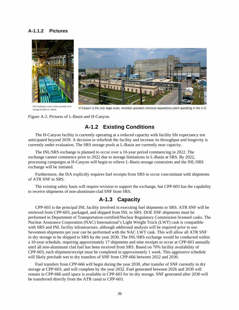
36
A-1.1.2 Pictures
Figure A-2. Pictures of L-Basin and H-Canyon.
A-1.2 Existing Conditions The H-Canyon facility is currently operating at a reduced capacity with facility life expectancy not
anticipated beyond 2039. A decision to refurbish the facility and increase its throughput and longevity is currently under evaluation. The SRS storage pools at L-Basin are currently near capacity.
The INL/SRS exchange is planned to occur over a 10-year period commencing in 2022. The exchange cannot commence prior to 2022 due to storage limitations in L-Basin at SRS. By 2022, processing campaigns at H-Canyon will begin to relieve L-Basin storage constraints and the INL/SRS exchange will be initiated.
Furthermore, the ISA explicitly requires fuel receipts from SRS to occur concomitant with shipments of ATR SNF to SRS.
The existing safety basis will require revision to support the exchange, but CPP-603 has the capability to receive shipments of non-aluminum-clad SNF from SRS.
A-1.3 Capacity CPP-603 is the principal INL facility involved in executing fuel shipments to SRS. ATR SNF will be
retrieved from CPP-603, packaged, and shipped from INL to SRS. DOE SNF shipments must be performed in Department of Transportation-certified/Nuclear Regulatory Commission licensed casks. The Nuclear Assurance Corporation (NAC) International’s Light Weight Truck (LWT) cask is compatible with SRS and INL facility infrastructure, although additional analysis will be required prior to use. Seventeen shipments per year can be performed with the NAC LWT cask. This will allow all ATR SNF in dry storage to be shipped to SRS by the year 2030. The INL/SRS exchange would be conducted within a 10-year schedule, requiring approximately 17 shipments and nine receipts to occur at CPP-603 annually until all non-aluminum clad fuel has been received from SRS. Based on 70% facility availability of CPP-603, each shipment/receipt must be completed in approximately 1 week. This aggressive schedule will likely preclude wet to dry transfers of SNF from CPP-666 between 2022 and 2030.
Fuel transfers from CPP-666 will begin during the year 2030, after transfer of SNF currently in dry storage at CPP-603, and will complete by the year 2032. Fuel generated between 2026 and 2030 will remain in CPP-666 until space is available in CPP-603 for its dry storage. SNF generated after 2030 will be transferred directly from the ATR canal to CPP-603.
37
ATR SNF is currently stored in 126 storage positions in CPP-603. An additional 63 positions in CPP-603 will be used for the 1,000 elements of ATR SNF that will be transferred from CPP-666 to dry storage in CPP-603 by the year 2021. With no additional reconfiguration, CPP-603 will reach capacity during the year 2021.
Shipments of ATR SNF to SRS will free up 189 storage locations in CPP-603; however, INL will receive approximately 2,000 elements of non-aluminum clad fuel from SRS to be placed into this space in dry storage. Without more efficient packaging of ATR SNF, CPP-603 would not be able to accommodate the entire 3,570 ATR SNF elements generated between 2016 and 2050.
A-1.4 Availability The ATR Canal, CPP-666, and CPP-603 are all currently operating facilities. All Navy and DOE-EM
fuel will have been removed from CPP-666 by 2021 and the only remaining SNF in CPP-666 will be ATR SNF pending transfer to SRS or dry storage. Therefore, the necessary INL resources are expected to be available to support the exchange.
For the purpose of this analysis (and consistent with the DOE evaluation of H-Canyon previously mentioned) H-Canyon, L-Basin, the Defense Waste Processing Facility or its replacement, and other SRS supporting facilities are assumed to be available. Facility descriptions and analysis focus on the INL facilities and process modifications that are required to implement the option for ATR SNF that is generated between 2017 and 2050.
A-2. ANALYSIS OF OPTION A-2.1 Description of the Facility
A-2.1.1 CPP-603
IFSF is located at the INTEC area of INL. Construction of IFSF proper was completed in December 1974. IFSF was designed to provide safe, interim, fuel storage pending retrieval of the stored fuel for final disposal. To meet this goal, the main operations performed in IFSF include receiving nuclear fuels from other facilities, repackaging and conditioning fuels for interim storage, safely storing fuels, storing fuel-loaded storage casks on an interim basis, and packaging fuels for removal from the facility (transfer).
IFSF is located in CPP-603, which is in the southwest corner of INTEC. CPP-603 consists of IFSF, the basin facility (closed and grouted), and common truck bays with overhead crane systems. IFSF’s functional areas include (1) the cask receiving area (including east/west truck bay, north/south truck bay, and truck ramp), (2) the cask transfer pit and permanent containment structure (PCS), (3) the fuel handling cave, (4) the fuel storage area, (5) the crane maintenance area, (6) the control and instrument rooms, (7) miscellaneous support areas, and (8) fuel storage basin interfaces. The miscellaneous support areas include a standby generator room (inactive); a heating, ventilating, and air conditioning (HVAC) equipment area (CPP-2710); and an access building (CPP-626) that is not considered part of IFSF. In the cask receiving area, fuel shipment packages are received and prepared for receipt into the IFSF fuel handling cave or prepared for shipment out of IFSF. Additionally, the cask receiving area is used for storage of shipping packages and storage of miscellaneous tools and equipment. In accordance with cask-specific analyses, the truck bays are used for interim storage of fuel-loaded storage casks. Operations and activities may be conducted in the various functional areas of the facility to test operational evolutions, to test equipment and tool function, and to perform dry runs.
Only those fuels specified in a contractor-approved fuel list (CAFL) may be received, handled, and stored at IFSF and only those casks on the contractor-approved cask list (CACL) may be loaded, unloaded, or stored at IFSF. In both cases, the activities are performed in accordance with the criticality safety requirements contained in the criticality safety controls list. The CAFL and CACL are derived from
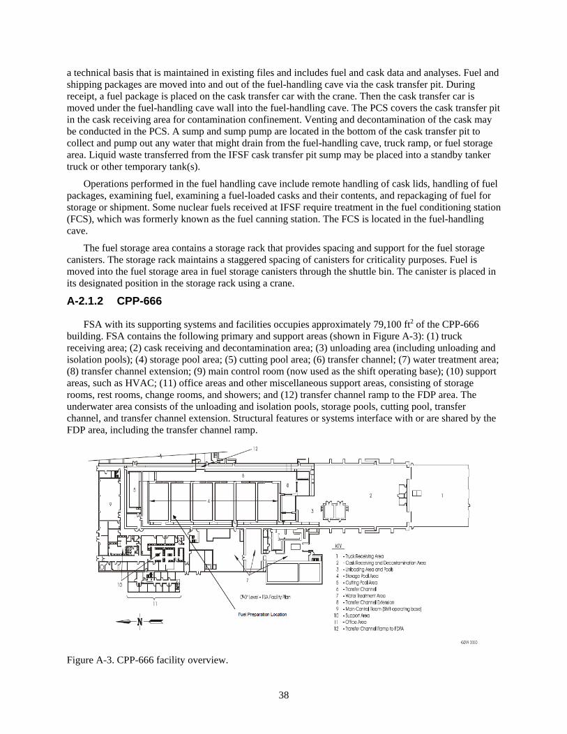
38
a technical basis that is maintained in existing files and includes fuel and cask data and analyses. Fuel and shipping packages are moved into and out of the fuel-handling cave via the cask transfer pit. During receipt, a fuel package is placed on the cask transfer car with the crane. Then the cask transfer car is moved under the fuel-handling cave wall into the fuel-handling cave. The PCS covers the cask transfer pit in the cask receiving area for contamination confinement. Venting and decontamination of the cask may be conducted in the PCS. A sump and sump pump are located in the bottom of the cask transfer pit to collect and pump out any water that might drain from the fuel-handling cave, truck ramp, or fuel storage area. Liquid waste transferred from the IFSF cask transfer pit sump may be placed into a standby tanker truck or other temporary tank(s).
Operations performed in the fuel handling cave include remote handling of cask lids, handling of fuel packages, examining fuel, examining a fuel-loaded casks and their contents, and repackaging of fuel for storage or shipment. Some nuclear fuels received at IFSF require treatment in the fuel conditioning station (FCS), which was formerly known as the fuel canning station. The FCS is located in the fuel-handling cave.
The fuel storage area contains a storage rack that provides spacing and support for the fuel storage canisters. The storage rack maintains a staggered spacing of canisters for criticality purposes. Fuel is moved into the fuel storage area in fuel storage canisters through the shuttle bin. The canister is placed in its designated position in the storage rack using a crane.
A-2.1.2 CPP-666
FSA with its supporting systems and facilities occupies approximately 79,100 ft2 of the CPP-666 building. FSA contains the following primary and support areas (shown in Figure A-3): (1) truck receiving area; (2) cask receiving and decontamination area; (3) unloading area (including unloading and isolation pools); (4) storage pool area; (5) cutting pool area; (6) transfer channel; (7) water treatment area; (8) transfer channel extension; (9) main control room (now used as the shift operating base); (10) support areas, such as HVAC; (11) office areas and other miscellaneous support areas, consisting of storage rooms, rest rooms, change rooms, and showers; and (12) transfer channel ramp to the FDP area. The underwater area consists of the unloading and isolation pools, storage pools, cutting pool, transfer channel, and transfer channel extension. Structural features or systems interface with or are shared by the FDP area, including the transfer channel ramp.
Figure A-3. CPP-666 facility overview.

39
A-2.2 Barriers to Implementation Use of CPP-666 for storage after the year 2023 to implement the fuel exchange with SRS will require
negotiation with the State of Idaho. Plans for transfer of wet-stored SNF to dry storage by 2021 would be inefficient and impact ATR operation without special accommodation for this option. Additionally, use of CPP-666 beyond April 2024 will require evaluation for facility life extension, including additional investment in physical upgrades.
The following are barriers to implementing fuel transfers to H-Canyon:
• DOE has not decided to extend operations/processing at H-Canyon.
• H-Canyon, L-Basin, and facilities supporting liquid waste processing at SRS will require extensive modifications and refurbishments to support operations through the year 2039.
• The SNF exchange between INL and SRS requires ATR SNF to remain in wet storage through at least 2030, which is not consistent with the ISA.
• Continued operation of the fuel pools at CPP-666 is costly and would likely require DOE-NE funding from 2022 to 2030 or beyond.
• Safety basis revisions will be required at CPP-603 to execute the fuel swap.
• Security requirements may impact SNF transfers between INTEC facilities and SNF shipments between SRS and INL.
A-2.3 Assumptions and Strategies • The NAC LWT cask can be used for ATR SNF transfers to SRS.
• The NAC LWT cask is capable of shipping 24 ATR SNF elements per shipment and ATR SNF shipped to SRS will meet the decay heat requirements specified in the certificate of compliance
• Readiness assessments will be required to verify readiness for SNF shipments to SRS from CPP-603 and CPP-666.
• CPP-603 will be capable of accepting 24 elements of ATR SNF in a location (16 elements per can on the first level and eight elements per can on the second level).
• Non-aluminum-clad SNF received from SRS can be packaged in the same configuration as ATR SNF in CPP-603 (see above).
• Discussions between DOE and the State of Idaho regarding the acceptability of wet storage of ATR SNF in CPP-666 pending shipment to SRS will occur before this option in enacted.
• Changes in the safeguards and security profile are not anticipated for CPP-666, CPP-603, or the ATR canal.
• Modification and/or equipment necessary to affect the fuel transfer will not require a line item capital project for INL facilities.
• ATR SNF can be direct transferred from the ATR canal to CPP-603 for dry storage once it is less than 30 watts/element.
• ATR SNF can be transferred to CPP-666 after 1 year of cooling in the ATR canal.
• This option is assumed to be consistent with the DOE SNF EIS and will not require additional NEPA analysis.
40
• NNSA and DOE-EM will fund costs related to SRS facilities; packaging and transportation of SNF to H-Canyon; retrieval of ATR SNF from dry storage; and dry storage of non-aluminum clad SNF received from SRS.
• DOE-NE will fund the cost of interim storage (wet and dry storage) for ATR SNF generated between 2016 and 2050.
A-2.4 Packaging the Fuel Not applicable.
A-2.5 Regulatory Issues Not applicable.
A-2.6 Cost (Capital and Operating) The principal costs associated with this option will be independent of the accommodation of ATR
SNF, consistent with the DOE economic analysis of H-Canyon processing options. No line item capital project will be required. However, to accommodate ATR SNF, this option must fund the operations of CPP-666 from 2022 through 2030; packaging and shipping 1,000 elements of ATR SNF to SRS; transfer of 2,570 elements into CPP-603; and one-fourth of the annual cost of CPP-603 operations from 2030 to 2050. A rough order of magnitude estimate for this option makes it a mid-range cost relative to the 12 options considered, assuming SRS process upgrades are financed independently from the SNF exchange.
A-2.7 Risk This option by itself does not provide a long-term solution for management of ATR SNF. This option
is viable only if it is combined with reconfiguration of CPP-603. DOE has not made a decision to resume H-Canyon operations at full capacity and a decision affecting this option would require a significant investment to refurbish and make process improvements to meet the necessary processing throughput and replace Defense Waste Processing Facility processing capability for HLW.
The other principal risk is associated with the need to retain ATR SNF in wet storage until the year 2030. This approach does not comply with the ISA milestone to have all SNF in dry storage by 2023. In addition to policy, regulatory, and cost risks, the schedule risk associated with the INL/SRS SNF exchange could extend the length of time ATR SNF is in wet storage.
A-2.8 Complexity This option is very complicated. Successfully enacting this option will involve inter-state
transportation; coordination between DOE-EM/NNSA/NE on funding; significant congressional appropriations; and significant coordination between INL and SRS facilities.
A-2.9 Stakeholder Value This option provides for ultimate disposition of 4,000 elements of ATR SNF. However, it also
requires wet storage of ATR SNF beyond the year 2023. Stakeholder reaction is assumed to be mixed. This option also provides for safe and cost-effective storage of ATR SNF pending construction of the ISFF and availability of a geologic repository.
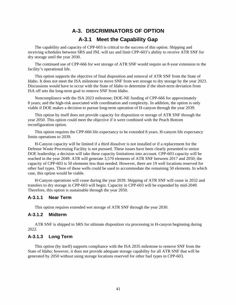
41
A-3. DISCRIMINATORS OF OPTION A-3.1 Meet the Capability Gap
The capability and capacity of CPP-603 is critical to the success of this option. Shipping and receiving schedules between SRS and INL will tax and limit CPP-603’s ability to receive ATR SNF for dry storage until the year 2030.
The continued use of CPP-666 for wet storage of ATR SNF would require an 8-year extension to the facility’s operational life.
This option supports the objective of final disposition and removal of ATR SNF from the State of Idaho. It does not meet the ISA milestone to move SNF from wet storage to dry storage by the year 2023. Discussions would have to occur with the State of Idaho to determine if the short-term deviation from ISA off sets the long-term goal to remove SNF from Idaho.
Noncompliance with the ISA 2023 milestone; DOE-NE funding of CPP-666 for approximately 8 years; and the high-risk associated with coordination and complexity. In addition, the option is only viable if DOE makes a decision to pursue long-term operation of H-canyon through the year 2039.
This option by itself does not provide capacity for disposition or storage of ATR SNF through the year 2050. This option could meet the objective if it were combined with the Peach Bottom reconfiguration option.
This option requires the CPP-666 life expectancy to be extended 8 years. H-canyon life expectancy limits operations to 2039.
H-Canyon capacity will be limited if a third dissolver is not installed or if a replacement for the Defense Waste Processing Facility is not pursued. These issues have been clearly presented to senior DOE leadership; a decision will take these capacity limitations into account. CPP-603 capacity will be reached in the year 2049. ATR will generate 3,570 elements of ATR SNF between 2017 and 2050; the capacity of CPP-603 is 50 elements less than needed. However, there are 19 well locations reserved for other fuel types. Three of these wells could be used to accommodate the remaining 50 elements. In which case, this option would be viable.
H-Canyon operations will cease during the year 2039. Shipping of ATR SNF will cease in 2032 and transfers to dry storage in CPP-603 will begin. Capacity in CPP-603 will be expended by mid-2049. Therefore, this option is sustainable through the year 2050.
A-3.1.1 Near Term
This option requires extended wet storage of ATR SNF through the year 2030.
A-3.1.2 Midterm
ATR SNF is shipped to SRS for ultimate disposition via processing in H-canyon beginning during 2022.
A-3.1.3 Long Term
This option (by itself) supports compliance with the ISA 2035 milestone to remove SNF from the State of Idaho; however, it does not provide adequate storage capability for all ATR SNF that will be generated by 2050 without using storage locations reserved for other fuel types in CPP-603.

42
A-3.2 Technical Complexity and Maturity of the Option Technically, the option is not highly complex for INL; however, it does present difficult challenges
that would have to be overcome at SRS. The option does not require any new technologies to be implemented. All operations have been previously performed; however, executing the option will require significant coordination.
Additional analysis and safety basis modifications are required for cask and packaging requirements for ATR SNF that will be shipped to SRS. Preliminary analysis indicates that approximately 17 shipments of ATR SNF will be required per year to SRS using the NAC LWT cask. The option also assumes that non-aluminum clad SNF can be stored in CPP-603 using the same configuration as ATR SNF. Further analysis of these assumptions is warranted. All INL facility operations assumed to occur in this option are either compatible or ongoing. Operational flexibility at CPP-603 will be limited during the SRS shipping campaign.
A-3.3 Meet Stakeholder, Legal, and Regulatory Requirements This option does not comply with the ISA 2023 milestone to remove all SNF from wet storage.
However, it does support the ISA milestone to remove all SNF from the State of Idaho by 2035.
A-3.4 Environment, Safety, and Health This option is consistent with EIS-0203, “Programmatic Final Environmental Impact Statement.” A
new environmental checklist/NEPA document will have to be prepared to assess the contemplated activities.
This option poses no adverse safety concerns because all operations are similar (or the same) as operations performed (or were performed in the recent past).
This option can be safely executed; however, further analysis is required for packaging and transportation and packaging configurations that will be used in CPP-603.
A-3.5 Schedule and Funding Limitations The schedule associated with this option is dependent on DOE’s decision to pursue increased
operation of H-Canyon. Once a decision has been made and funds for SRS modifications and maintenance requested; INL planning will begin to support packaging and transportation. Funding to support INL planning activities will be required by no later than 2019. Funding for CPP-666 operations and packaging and shipment of ATR SNF will be required beginning in 2022 and funds for wet to dry transfers will be needed beginning in approximately 2030.

43
Figure A-4. Option 1 timetable.
A-3.6 Interfaces and Integration Requirements As previously discussed, this option will require extensive interface and integration between DOE-
EM, NNSA, and DOE-NE. In addition, interface and integration between INL and SRS will be crucial. An external interface will be required with state and tribal governments to execute the transfer of SNF from INL to SRS.
A-3.7 Safeguards and Security Safeguards and security will need to evaluate non-aluminum clad SNF that will be received at INL to
determine if changes in the safeguards and security posture of CPP-603 will be required. Changing safeguards and security requirements could impact inter-state transfer of SNF.
A-3.8 Near-Term Cost This option has low initial investment. Relative to the other options evaluated, the near-term cost of
this option is low, assuming SRS process upgrades are financed independently from the SNF exchange.
A-3.8.1 Initial Costs
• No line item capital project will be required.
External Schedule Constraints
•Fun
ding
ava
ilabl
eIF
SF re
ache
s cap
acity
(16
ATR
SNF
/ por
t)
•ATR
Can
al a
t cap
acity
unle
ss S
NF sh
ips
•ISA
- al
l INL
SNF
out
of w
et st
orag
e by
en
d of
yea
r
•Ass
umed
last
ATR
SNF
gen
erat
ed(b
asis
of d
efin
ed sc
ope)
•Rep
osito
ry a
ccep
ts A
TR S
NF
2016 2017 2019 2020 2022 2023 > 2030 >> 2050 > 2055
•DO
E ch
oose
s to
upgr
ade
H-Ca
nyon
•Res
ume
ship
ping
of A
TR S
NFto
CPP
-666
•Beg
in sh
ipm
ent f
rom
CPP
-666
to S
RS
•Wet
to d
ry tr
ansf
ers b
egin
(24
ATR
SNF
/ por
t)
•Rem
aini
ng A
TR S
NF d
ry st
ored
(afte
r co
olin
g at
ATR
Can
al)
Timetable for Option 1

44
• Initial investment cost is likely to include development costs associated with use of the NAC LWT cask in the INL and SRS facilities.
A-3.9 Life-Cycle Cost Overall this option is of mid-range cost relative to the other options considered. Life-cycle cost
includes both the initial costs and the recurring costs accumulated over the life of the ATR SNF.
A-3.9.1 Recurring Costs
• This option requires financing CPP-666 operations between the years 2022 and 2030.
• Packaging and shipping of 1,000 elements of ATR SNF to SRS will occur between the years 2030 and 2032.
• Transfer of 2,570 elements into CPP-603 will occur between the years 2030 and 2050.
• Annual maintenance and operating investments will be expended on the CPP-603 facility from the years 2030 to 2050.
The use of CPP-666 beyond April 2024 will also require evaluation for facility life extension. These costs were not defined or bounded in this rough estimate and physical upgrades for security contribute significant financial risk to this option.
A-4. RECOMMENDATION FOR OPTION This option should not be pursued as a stand-alone option. The option should be pursued in tandem
with another option if and when DOE makes a decision to proceed with the 4,000 ATR element transfer or optimization of highly enriched uranium recovery at H-Canyon.

45
Appendix B
Option 2: Dry Storage at NRF in a Road-Ready Configuration with an FSA Interface

46
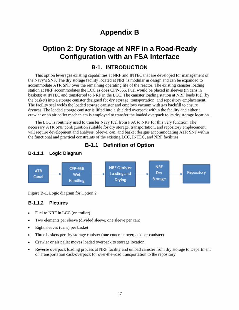
47
Appendix B
Option 2: Dry Storage at NRF in a Road-Ready Configuration with an FSA Interface
B-1. INTRODUCTION This option leverages existing capabilities at NRF and INTEC that are developed for management of
the Navy’s SNF. The dry storage facility located at NRF is modular in design and can be expanded to accommodate ATR SNF over the remaining operating life of the reactor. The existing canister loading station at NRF accommodates the LCC as does CPP-666. Fuel would be placed in sleeves (in cans in baskets) at INTEC and transferred to NRF in the LCC. The canister loading station at NRF loads fuel (by the basket) into a storage canister designed for dry storage, transportation, and repository emplacement. The facility seal welds the loaded storage canister and employs vacuum with gas backfill to ensure dryness. The loaded storage canister is lifted into a shielded overpack within the facility and either a crawler or an air pallet mechanism is employed to transfer the loaded overpack to its dry storage location.
The LCC is routinely used to transfer Navy fuel from FSA to NRF for this very function. The necessary ATR SNF configuration suitable for dry storage, transportation, and repository emplacement will require development and analysis. Sleeve, can, and basket designs accommodating ATR SNF within the functional and practical constraints of the existing LCC, INTEC, and NRF facilities.
B-1.1 Definition of Option B-1.1.1 Logic Diagram
Figure B-1. Logic diagram for Option 2.
B-1.1.2 Pictures
• Fuel to NRF in LCC (on trailer)
• Two elements per sleeve (divided sleeve, one sleeve per can)
• Eight sleeves (cans) per basket
• Three baskets per dry storage canister (one concrete overpack per canister)
• Crawler or air pallet moves loaded overpack to storage location
• Reverse overpack loading process at NRF facility and unload canister from dry storage to Department of Transportation cask/overpack for over-the-road transportation to the repository
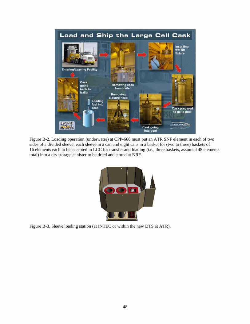
48
Figure B-2. Loading operation (underwater) at CPP-666 must put an ATR SNF element in each of two sides of a divided sleeve; each sleeve in a can and eight cans in a basket for (two to three) baskets of 16 elements each to be accepted in LCC for transfer and loading (i.e., three baskets, assumed 48 elements total) into a dry storage canister to be dried and stored at NRF.
Figure B-3. Sleeve loading station (at INTEC or within the new DTS at ATR).
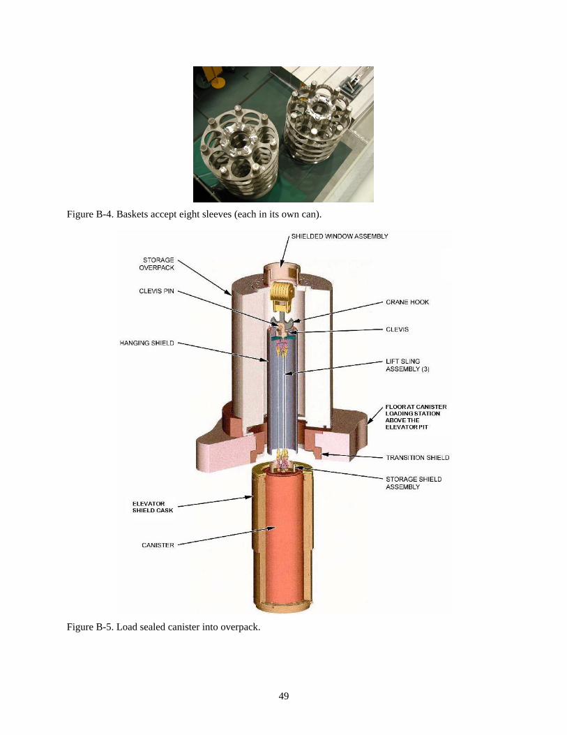
49
Figure B-4. Baskets accept eight sleeves (each in its own can).
Figure B-5. Load sealed canister into overpack.
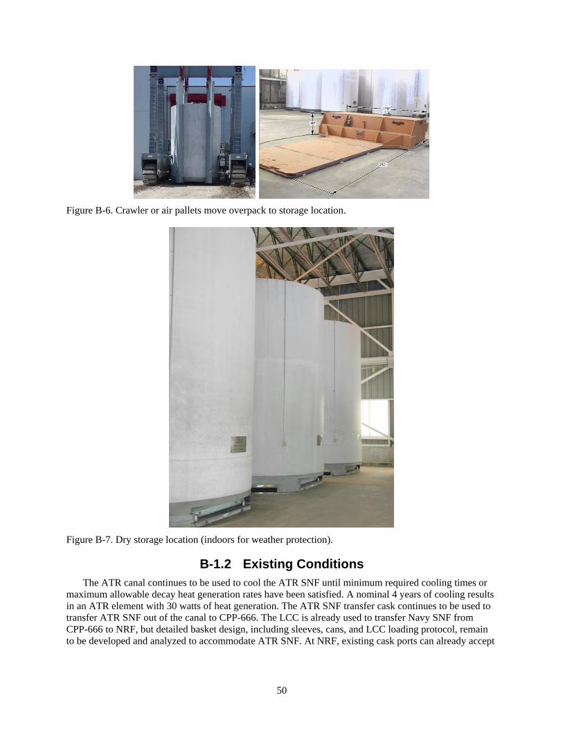
50
Figure B-6. Crawler or air pallets move overpack to storage location.
Figure B-7. Dry storage location (indoors for weather protection).
B-1.2 Existing Conditions The ATR canal continues to be used to cool the ATR SNF until minimum required cooling times or
maximum allowable decay heat generation rates have been satisfied. A nominal 4 years of cooling results in an ATR element with 30 watts of heat generation. The ATR SNF transfer cask continues to be used to transfer ATR SNF out of the canal to CPP-666. The LCC is already used to transfer Navy SNF from CPP-666 to NRF, but detailed basket design, including sleeves, cans, and LCC loading protocol, remain to be developed and analyzed to accommodate ATR SNF. At NRF, existing cask ports can already accept
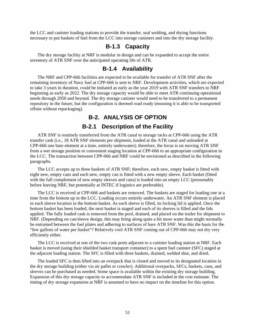
51
the LCC and canister loading stations to provide the transfer, seal welding, and drying functions necessary to put baskets of fuel from the LCC into storage canisters and into the dry storage facility.
B-1.3 Capacity The dry storage facility at NRF is modular in design and can be expanded to accept the entire
inventory of ATR SNF over the anticipated operating life of ATR.
B-1.4 Availability The NRF and CPP-666 facilities are expected to be available for transfer of ATR SNF after the
remaining inventory of Navy fuel at CPP-666 is sent to NRF. Development activities, which are expected to take 3 years in duration, could be initiated as early as the year 2019 with ATR SNF transfers to NRF beginning as early as 2022. The dry storage capacity would be able to meet ATR continuing operational needs through 2050 and beyond. The dry storage canister would need to be transferred to a permanent repository in the future, but the configuration is deemed road ready (meaning it is able to be transported offsite without repackaging).
B-2. ANALYSIS OF OPTION B-2.1 Description of the Facility
ATR SNF is routinely transferred from the ATR canal to storage racks at CPP-666 using the ATR transfer cask (i.e., 18 ATR SNF elements per shipment, loaded at the ATR canal and unloaded at CPP-666 one bare element at a time, entirely underwater); therefore, the focus is on moving ATR SNF from a wet storage position or convenient staging location at CPP-666 to an appropriate configuration in the LCC. The transaction between CPP-666 and NRF could be envisioned as described in the following paragraphs.
The LCC accepts up to three baskets of ATR SNF; therefore, each new, empty basket is fitted with eight new, empty cans and each new, empty can is fitted with a new empty sleeve. Each basket (fitted with the full complement of new empty sleeves and cans) is loaded into an empty LCC (presumably before leaving NRF, but potentially at INTEC if logistics are preferable).
The LCC is received at CPP-666 and baskets are removed. The baskets are staged for loading one at a time from the bottom up in the LCC. Loading occurs entirely underwater. An ATR SNF element is placed in each sleeve location in the bottom basket. As each sleeve is filled, its locking lid is applied. Once the bottom basket has been loaded, the next basket is staged and each of its sleeves is filled and the lids applied. The fully loaded cask is removed from the pool, drained, and placed on the trailer for shipment to NRF. (Depending on can/sleeve design, this may bring along quite a bit more water than might normally be entrained between the fuel plates and adhering to surfaces of bare ATR SNF. Was this the basis for the “few gallons of water per basket”? Relatively cool ATR SNF coming out of CPP-666 may not dry very efficiently either.
The LCC is received at one of the two cask ports adjacent to a canister loading station at NRF. Each basket is moved (using their shielded basket transport container) to a spent fuel canister (SFC) staged at the adjacent loading station. The SFC is filled with three baskets, drained, welded shut, and dried.
The loaded SFC is then lifted into an overpack that is closed and moved to its designated location in the dry storage building (either via air pallet or crawler). Additional overpacks, SFCs, baskets, cans, and sleeves can be purchased as needed. Some space is available within the existing dry storage building. Expansion of this dry storage capacity to accommodate ATR SNF is included in the cost estimate. The timing of dry storage expansion at NRF is assumed to have no impact on the timeline for this option.

52
B-2.2 Barriers to Implementation • Significant organizational interdependencies and interfaces with high potential for conflicting
priorities (i.e., funding authority, operational authority, and obligations to stakeholders).
• Potential for technical issue associated with the quantity of water transferred with ATR SNF during underwater loading of the LCC.
• Potential for technical issues with SFC penetration (calculated canister life) at the repository allowing premature loss of ATR SNF configuration (due to more rapid corrosion of aluminum-clad fuel compared to Navy fuel materials) and unacceptable risk of criticality.
B-2.3 Assumptions and Strategies Assumes 3 years of development time. Move forward with funding for safety analysis and design by
the year 2019 or the ATR canal runs out of capacity in 2020. Assumes the DOE Office of Naval Reactors safeguards and security can readily adapt their existing systems and practices to accommodate ATR SNF. Assumes use of CPP-666 for ATR SNF transfer from the ATR cask to LCC is acceptable until the year 2051 to enable all ATR SNF to be transferred to dry storage after ATR shut down.
B-2.4 Packaging the Fuel The existing ATR SNF transfer cask is used for wet-to-wet transfer of ATR SNF to CPP-666. The
existing CPP-666 facilities would be used to load ATR SNF into the LCC to interface with the existing capabilities at NRF. The ATR SNF is assumed to be in good condition with no known cladding breach at the time of transfer to dry storage. The resultant dry storage SFC is road ready for offsite transport when repository is available to accept DOE SNF.
B-2.5 Regulatory Issues NEPA compliance must be verified, but the existing facility infrastructure is used.
B-2.6 Cost (Capital and Operating) Capital costs are minimal with the use of existing facilities (with expansion of the modular dry
storage at NRF); and preliminary costs are low, including basket and storage configuration development specific to ATR SNF (including NEPA evaluation). The accumulated recurring costs are high and account for facility maintenance and labor at CPP-666, canister procurement, canister loading at NRF, expansion of NRF storage, and eventual costs to transport the canisters to a repository.
B-2.7 Risk ATR SNF-specific configuration development is needed, but existing facility infrastructure at ATR,
INTEC, and NRF is sufficient for all requisite operations. Stakeholder acceptance of continued use of CPP-666 must be negotiated.
B-2.8 Complexity This option employs existing infrastructure to accomplish dry storage of ATR SNF. Use of the ATR
transfer cask and the LCC with transfer at CPP-666 facilitates compatibility of all structures, systems, and components involved. The complexity is due to the multiplicity of organizational interfaces rather than the technological development needed for implementation.
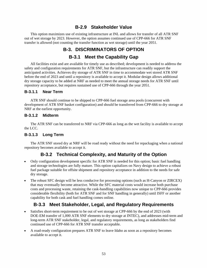
53
B-2.9 Stakeholder Value This option maximizes use of existing infrastructure at INL and allows for transfer of all ATR SNF
out of wet storage by 2023. However, the option assumes continued use of CPP-666 for ATR SNF transfer is allowed (not counting the transfer function as wet storage) until the year 2051.
B-3. DISCRIMINATORS OF OPTION B-3.1 Meet the Capability Gap
All facilities exist and are available for timely use as described; development is needed to address the safety and configuration requirements for ATR SNF, but the infrastructure can readily support the anticipated activities. Achieves dry storage of ATR SNF in time to accommodate wet stored ATR SNF before the end of 2023 and until a repository is available to accept it. Modular design allows additional dry storage capacity to be added at NRF as needed to meet the annual storage needs for ATR SNF until repository acceptance, but requires sustained use of CPP-666 through the year 2051.
B-3.1.1 Near Term
ATR SNF should continue to be shipped to CPP-666 fuel storage area pools (concurrent with development of ATR SNF basket configuration) and should be transferred from CPP-666 to dry storage at NRF at the earliest opportunity.
B-3.1.2 Midterm
The ATR SNF can be transferred to NRF via CPP-666 as long as the wet facility is available to accept the LCC.
B-3.1.3 Long Term
The ATR SNF stored dry at NRF will be road ready without the need for repackaging when a national repository becomes available to accept it.
B-3.2 Technical Complexity, and Maturity of the Option • Only configuration development specific for ATR SNF is needed for this option; basic fuel handling
and storage technologies are fully mature. This option capitalizes on Navy design to achieve a robust fuel package suitable for offsite shipment and repository acceptance in addition to the needs for safe dry storage.
• The robust SFC design will be less conducive for processing options (such as H-Canyon or ZIRCEX) that may eventually become attractive. While the SFC material costs would increase both purchase costs and processing waste, retaining the cask-handling capabilities now unique to CPP-666 provides considerable flexibility (both for ATR SNF and for SNF handling in generally) until ISFF or another capability for both cask and fuel handling comes online.
B-3.3 Meet Stakeholder, Legal, and Regulatory Requirements • Satisfies short-term requirement to be out of wet storage at CPP-666 by the end of 2023 (with
DOE-EM transfer of 1,000 ATR SNF elements to dry storage at INTEC), and addresses mid-term and long-term ATR SNF stakeholder, legal, and regulatory requirements, as long as stakeholders find continued use of CPP-666 for ATR SNF transfer acceptable.
• A road-ready configuration prepares ATR SNF to leave Idaho as soon as a repository becomes available to accept it.

54
• Risk of other constraints is incumbent to stakeholder negotiation to support using CPP-666 for ATR SNF transfer until the year 2051.
B-3.4 Environment, Safety, and Health • NEPA evaluation will be needed; however, because this option uses existing facilities, an
environmental assessment is assumed to satisfy this requirement.
• The capabilities for all basic functions required for fuel handling are already available and in use (a safety advantage compared to start of new operations or new facilities). For some considerations, wet storage of ATR SNF may be safer until decay heat is further reduced.
B-3.5 Schedule and Funding Limitations • 3 years to develop and analyze ATR SNF-specific technical features; therefore, transfer of ATR SNF
to NRF begins in 2022.
• Transfer and storage facilities can accommodate the 105 ATR SNF per year generation rate over the projected life of ATR.
• Accrues increase the financial burden for use of CPP-666 as the Navy and DOE-EM remove their fuel and operations from the facility to satisfy ISA.
Figure B-8. Option 2 timetable.
External Schedule Constraints
•Fun
ding
ava
ilabl
e•I
FSF
reac
hes c
apac
ity(1
6 AT
R SN
F / p
ort)
•ATR
Can
al a
t cap
acity
unle
ss S
NF sh
ips
•ISA
- al
l INL
SNF
out
of w
et st
orag
e by
en
d of
yea
r
•Ass
umed
last
ATR
SNF
gen
erat
ed(b
asis
of d
efin
ed sc
ope)
•Rep
osito
ry a
ccep
ts A
TR S
NF2016 2017 2019 2020 2022 2023 >> 2050 > 2055
•Res
ume
ship
ping
of A
TR S
NFto
CPP
-666
•NEP
A EA
take
s 6 m
onth
s•S
tart
3 y
ears
for c
anist
er &
bas
ket
deve
lopm
ent
•Beg
in tr
anfe
rs to
NRF
Dry
Sto
rage
•Rem
aini
ng A
TR S
NF d
ry st
ored
at N
RF
(afte
r coo
ling
at A
TR C
anal
)
Timetable for Option 2

55
B-3.6 Interfaces and Integration Requirements • DOE-NE
• ATR contractor
• INTEC contractor
• NRF operations
• DOE-EM
• DOE Office of Naval Reactors
• DOE Headquarters
• Stakeholders.
B-3.7 Safeguards and Security Use of the CPP-666 facility beyond April 2024 is NOT within the security plan.
B-3.8 Near-Term Cost Relative to the other options evaluated, the near-term cost of this option is low, accounting for the
following two main considerations.
• Development costs (including basket design and initial fabrication)
• NEPA compliance – environmental assessment evaluation.
B-3.9 Life-Cycle Cost Overall, this option is high cost: this is one of the most expensive options considered. Life cycle cost
includes both the initial costs identified as near-term cost and recurring costs accumulated over the life of the ATR SNF.
B-3.9.1 Recurring Costs
• Projected NRF operating cost per ATR SNF element
• Transfer costs, including facility rate for use of CPP-666 plus loading and unloading operating costs (shared by Navy until the 2018 to 2019 timeframe and shared by DOE-EM until 2020, with full cost assumed by DOE-NE for ATR SNF transfers from 2020 to 2051)
• Material costs (depending on loading and using a nominal 48 elements/SFC for consistency)
• Annual security, maintenance, or monitoring costs associated with dry storage of ATR SNF at NRF has not been included; allowance was made for necessary expansion of the dry storage facility at NRF
• Costs for transfer from dry storage at NRF to repository.
The use of CPP-666 beyond April 2024 will also require evaluation for facility life extension. These costs were not defined or bounded in this rough estimate and physical upgrades for security contribute significant financial risk to this option.
Also, while many of the other options rely on ISFF for repository transfer (and do not specifically address the associated cost), even without the repository transfer costs, this would still be a high-cost option.

56
B-4. RECOMMENDATION FOR OPTION This option is feasible only with stakeholder flexibility regarding the use of CPP-666 for fuel transfer
well beyond the removal of SNF from wet storage by end of the year 2023. Use of CPP-666 for ATR SNF transfer purposes becomes progressively more expensive. This option is not a preferred option because, although it allows efficient use of existing capabilities at INL, it is one of the more expensive options. The expense is largely spread across the remaining life of ATR and avoids delays associated with major construction projects. While material costs for packaging into a road-ready SFC contribute to the high life-cycle cost, the investment does avoid the need for future repackaging.

57
Appendix C
Option 3: Dry Storage at NRF in a Road-Ready Configuration with a Dry Transfer at ATR

58
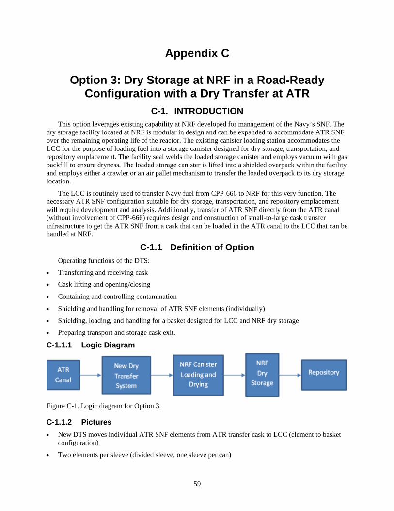
59
Appendix C
Option 3: Dry Storage at NRF in a Road-Ready Configuration with a Dry Transfer at ATR
C-1. INTRODUCTION This option leverages existing capability at NRF developed for management of the Navy’s SNF. The
dry storage facility located at NRF is modular in design and can be expanded to accommodate ATR SNF over the remaining operating life of the reactor. The existing canister loading station accommodates the LCC for the purpose of loading fuel into a storage canister designed for dry storage, transportation, and repository emplacement. The facility seal welds the loaded storage canister and employs vacuum with gas backfill to ensure dryness. The loaded storage canister is lifted into a shielded overpack within the facility and employs either a crawler or an air pallet mechanism to transfer the loaded overpack to its dry storage location.
The LCC is routinely used to transfer Navy fuel from CPP-666 to NRF for this very function. The necessary ATR SNF configuration suitable for dry storage, transportation, and repository emplacement will require development and analysis. Additionally, transfer of ATR SNF directly from the ATR canal (without involvement of CPP-666) requires design and construction of small-to-large cask transfer infrastructure to get the ATR SNF from a cask that can be loaded in the ATR canal to the LCC that can be handled at NRF.
C-1.1 Definition of Option Operating functions of the DTS:
• Transferring and receiving cask
• Cask lifting and opening/closing
• Containing and controlling contamination
• Shielding and handling for removal of ATR SNF elements (individually)
• Shielding, loading, and handling for a basket designed for LCC and NRF dry storage
• Preparing transport and storage cask exit.
C-1.1.1 Logic Diagram
Figure C-1. Logic diagram for Option 3.
C-1.1.2 Pictures • New DTS moves individual ATR SNF elements from ATR transfer cask to LCC (element to basket
configuration)
• Two elements per sleeve (divided sleeve, one sleeve per can)
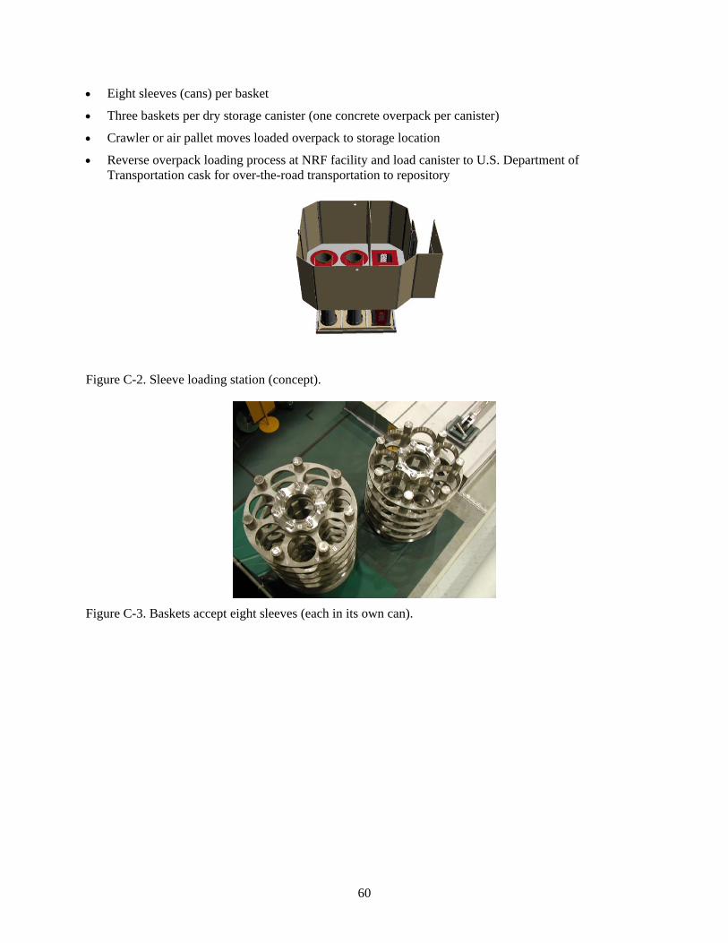
60
• Eight sleeves (cans) per basket
• Three baskets per dry storage canister (one concrete overpack per canister)
• Crawler or air pallet moves loaded overpack to storage location
• Reverse overpack loading process at NRF facility and load canister to U.S. Department of Transportation cask for over-the-road transportation to repository
Figure C-2. Sleeve loading station (concept).
Figure C-3. Baskets accept eight sleeves (each in its own can).
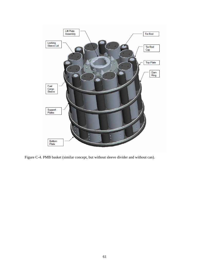
61
Figure C-4. PMB basket (similar concept, but without sleeve divider and without can).
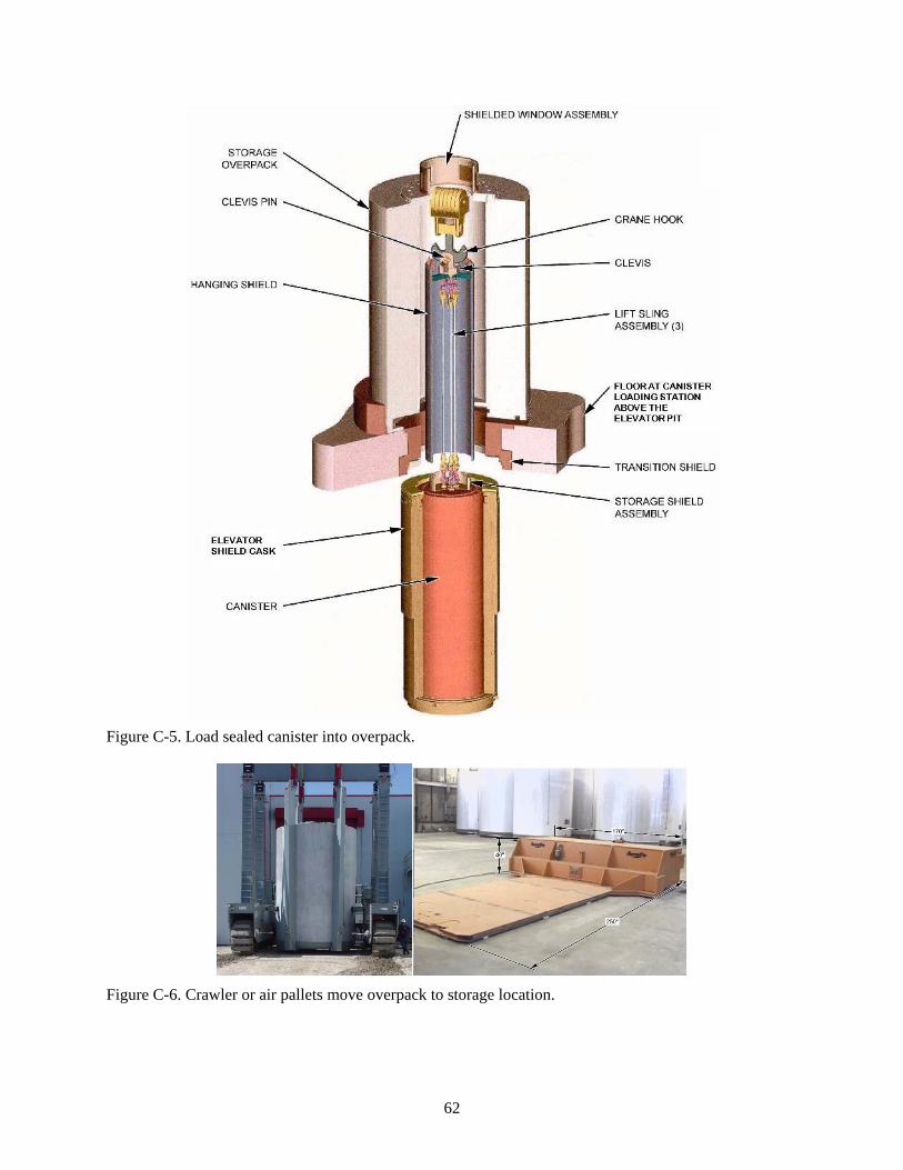
62
Figure C-5. Load sealed canister into overpack.
Figure C-6. Crawler or air pallets move overpack to storage location.
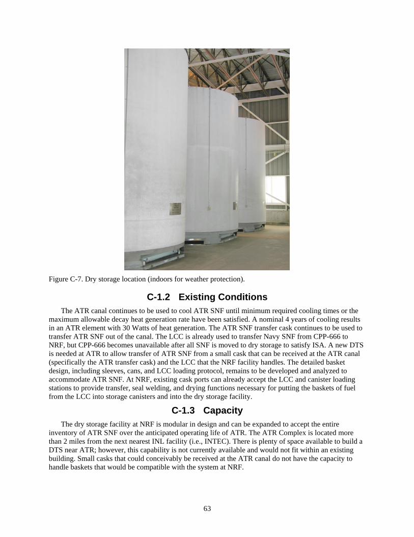
63
Figure C-7. Dry storage location (indoors for weather protection).
C-1.2 Existing Conditions The ATR canal continues to be used to cool ATR SNF until minimum required cooling times or the
maximum allowable decay heat generation rate have been satisfied. A nominal 4 years of cooling results in an ATR element with 30 Watts of heat generation. The ATR SNF transfer cask continues to be used to transfer ATR SNF out of the canal. The LCC is already used to transfer Navy SNF from CPP-666 to NRF, but CPP-666 becomes unavailable after all SNF is moved to dry storage to satisfy ISA. A new DTS is needed at ATR to allow transfer of ATR SNF from a small cask that can be received at the ATR canal (specifically the ATR transfer cask) and the LCC that the NRF facility handles. The detailed basket design, including sleeves, cans, and LCC loading protocol, remains to be developed and analyzed to accommodate ATR SNF. At NRF, existing cask ports can already accept the LCC and canister loading stations to provide transfer, seal welding, and drying functions necessary for putting the baskets of fuel from the LCC into storage canisters and into the dry storage facility.
C-1.3 Capacity The dry storage facility at NRF is modular in design and can be expanded to accept the entire
inventory of ATR SNF over the anticipated operating life of ATR. The ATR Complex is located more than 2 miles from the next nearest INL facility (i.e., INTEC). There is plenty of space available to build a DTS near ATR; however, this capability is not currently available and would not fit within an existing building. Small casks that could conceivably be received at the ATR canal do not have the capacity to handle baskets that would be compatible with the system at NRF.

64
C-1.4 Availability A capital project necessary for the design and construction of the requisite DTS would likely require
full compliance with DOE Order 413.3B, which could require 5 to 7 years to complete planning, design, construction, readiness, and startup testing. Acceleration of this compliance process is unlikely to allow dry transfer of ATR SNF from the ATR canal starting in 2022. An expedited (4-year) DOE Order 413.3B process (capitalizing on the existing design at NRF and the need for mutual interface with the LCC and fuel baskets) would allow transfer of ATR SNF out of the ATR canal to NRF no earlier than 2023, and likely much later. However, the NRF facility is expected to be available to receive transfer of ATR SNF after the remaining inventory of Navy fuel at CPP-666 is sent to NRF in 2022. Development activities, expected to take 3 years duration, could be initiated as early as 2019 with ATR SNF transfers to NRF beginning as early as the dry transfer could be performed. The dry storage capacity would be able to meet ATR continuing operational needs through 2050 and beyond. The dry storage canister would need to be transferred to a permanent repository in the future, but the configuration is deemed road ready - able to be transported offsite without repackaging.
C-2. ANALYSIS OF OPTION C-2.1 Description of the Facility
ATR SNF is routinely transferred from the ATR canal to storage racks at CPP-666 using the ATR transfer cask (eight ATR SNF elements per shipment, loaded at the ATR canal, underwater, one bare element at a time); therefore, the focus is on moving ATR SNF from the ATR transfer cask to an appropriate basket configuration in the LCC. The transfer from handling individual ATR SNF elements to ATR SNF configured in a basket would occur within the new DTS. Trailers would deliver and receive the ATR cask and the LCC to the new DTS. The transaction between DTS and NRF is functionally equivalent to the transaction between CPP-666 and NRF once the LCC is fully loaded.
The LCC accepts up to three baskets of ATR SNF, corresponding to at least one ATR transfer cask shipment per basket. Therefore, the shielded basket holding capacity at the DTS would reduce the commitment of the LCC to transfer between full payloads. (The design of the NRF shielded basket transfer container [SBTC] could be employed for this purpose. Three of them would enable the DTS to house partial or full baskets up to a full LCC payload, freeing up the LCC while the smaller ATR cask makes multiple shipments out of the ATR canal to the DTS.)
The DTS must remove individual ATR SNF elements from the ATR transfer cask and place them in a sleeve (partitioned to hold two elements per sleeve) in a can that is in a basket. An empty basket would be fitted with eight new empty cans and each new empty cans fitted with a new empty sleeve. Each basket (fitted with the full complement of new empty sleeves and cans) could either be loaded into an empty SBTC or shielded loading area at DTS (new materials could be partially staged manually before they might become contaminated in any way).
The basket would be staged for loading at the DTS and loaded remotely. Alternately, a shielded element transfer container, similar to the SBTC in function (only much smaller), could be used for this purpose using an indexing system mounted to a shield door fitted to the SBTC or LCC or shielded loading port (to track and allow pass through of the element from the shielded element transfer container to the partition position for each position in the basket). As each sleeve is filled, its locking lid would be applied (if this feature is included in the ATR SNF sleeve design). The loaded basket could potentially be housed in an SBTC until a full LCC payload was ready.
Then the empty LCC could be received and loaded with full baskets, employing the transfer function of the SBTC. The full LCC would be installed on the trailer and delivered to NRF. The LCC is received at one of the two cask ports adjacent to a canister loading station at NRF. Each basket is moved (using their SBTC) to an SFC staged at the adjacent loading station. The SFC is filled with three baskets,

65
drained, welded shut, and dried. Solely from waters of hydration associated with the aluminum cladding, 3 gallons of water per SFC would likely remain with the fuel after drying.
The loaded SFC is then lifted into an overpack, which is closed and moved to its designated location in the dry storage building (either via air pallet or crawler). Additional overpacks, SFCs, baskets, cans, and sleeves can be purchased as needed. Some space is available within the existing dry storage building. Expansion of this dry storage capacity to accommodate ATR SNF is included in the cost estimate. The timing of dry storage expansion at NRF is assumed to have no impact on the timeline for this option.
C-2.2 Barriers to Implementation • Significant potential for delays in the capital project required for development, construction, and
initial operation of the new DTS
• Some organizational interdependencies and interfaces with potential for conflicting priorities (i.e., funding authority, operational authority, and obligations to stakeholders).
• Potential for technical issues with SFC penetration (calculated canister life) at the repository, allowing premature loss of ATR SNF configuration (due to more rapid corrosion of aluminum-clad fuel compared to Navy fuel materials) and unacceptable risk of criticality.
C-2.3 Assumptions and Strategies Assumes 3 years of development time for ATR SNF configuration for dry storage at NRF. Move
forward with funding of safety analysis and design by the year 2019 and the ATR canal runs out of capacity in 2022. Assumes Office of Naval Reactors Safeguards and Security can readily adapt their existing systems and practices to accommodate ATR SNF.
C-2.4 Packaging the Fuel The existing ATR spent fuel element transfer cask is used for wet-to-wet transfer of ATR SNF to
CPP-666 to allow lag storage in 2022 and 2023. The new DTS would be used to load ATR SNF from the ATR cask to baskets to the LCC to interface with the existing capabilities at NRF. ATR SNF is assumed to be in good condition with no known cladding breach at the time of transfer to dry storage. The resultant dry storage SFC is road ready for offsite transport when a repository is available to accept DOE SNF.
C-2.5 Regulatory Issues NEPA compliance must be verified. New infrastructure for DTS will require an EIS.
C-2.6 Cost (Capital and Operating) Design and construction of the DTS require a large investment for the preliminary (capital) costs.
Basket and storage configuration development specific to ATR SNF and NEPA evaluation add to the initial costs. The accumulated recurring costs are much larger than the initial investment for this option, including transfer facility maintenance and labor, canister procurement, canister loading at NRF, expansion of NRF storage, and eventual transport of the canisters to a repository.
C-2.7 Risk Schedule delays are a significant risk to developing and completing construction of the necessary
DTS.
C-2.8 Complexity This option employs existing infrastructure to accomplish dry storage of ATR SNF. Use of the ATR
transfer cask and the LCC with transfer at a new DTS ensures compatibility of all structures, systems, and components involved. Concepts from the NRF canister loading station simplify the dry transfer strategy.

66
Some complexity is due to the organizational interfaces and the need for compliance with the DOE Order 413.3B process rather than the technological development needed for implementation.
C-2.9 Stakeholder Value This option uses existing infrastructure at NRF and minimizes use of wet facilities, but requires an
overly aggressive (i.e., 4-year) schedule for a new DTS and other near-term actions be taken to ensure ATR SNF is out of wet storage by the end of the year 2023.
C-3. DISCRIMINATORS OF OPTION C-3.1 Meet the Capability Gap
The DOE Order 413.3B process needs to be accelerated to minimize potential impact to near-term ATR SNF storage. The authorization process in conjunction with the need to both use and vacate CPP-666 in 2022 and 2023 to support this option makes for a very high schedule risk. Dry storage capacity can be added at NRF as needed to meet the storage needs for ATR SNF.
C-3.1.1 Near Term ATR SNF should be shipped to CPP-666 FAST pools to allow uninterrupted reactor operation in
2022 and should be transferred from CPP-666 to dry storage at NRF at the earliest opportunity.
C-3.1.2 Midterm The ATR SNF can be transferred to NRF via the DTS until the ATR reactor completes its mission.
C-3.1.3 Long Term The ATR SNF stored dry at NRF will be road ready without the need for repackaging when a national
repository becomes available to accept it.
C-3.2 Technical Complexity and Maturity of the Option • Configuration development specific for ATR SNF is needed for this option; the basic fuel handling
and storage technologies are fully mature. Even indexing and shielding for the dry transfer has been developed for other applications.
• This option packages ATR SNF to be road ready for repository acceptance. The robust SFC design will be less conducive for processing options (such as H-Canyon or ZIRCEX) that may eventually become attractive. The SFC material costs would increase both purchase costs and processing waste; however, the new dry transfer capability could provide some flexibility (both for ATR SNF and for SNF handling in general) in allowing receipt of the LCC with a dry shielded interface until ISFF or other capability for both large cask and single element handling comes online. The ATR SNF element to basket to LCC transfer being handled dry is beneficial in limiting the quantity of pool water transferred with the SNF to the LCC.
C-3.3 Meet Stakeholder, Legal, and Regulatory Requirements This option does not satisfy the short-term requirement to be out of wet storage at CPP-666 by end of
2023 without an accelerated schedule and use of CPP-666 for lag storage. However, it does address the midterm and long-term ATR SNF stakeholder, legal, and regulatory requirements.
C-3.4 Environment, Safety, and Health NEPA evaluation will be needed and due to new infrastructure for the DTS, an EIS is assumed to
satisfy this requirement.
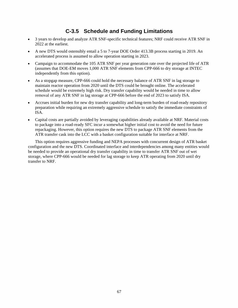
67
C-3.5 Schedule and Funding Limitations • 3 years to develop and analyze ATR SNF-specific technical features; NRF could receive ATR SNF in
2022 at the earliest.
• A new DTS would ostensibly entail a 5 to 7-year DOE Order 413.3B process starting in 2019. An accelerated process is assumed to allow operation starting in 2023.
• Campaign to accommodate the 105 ATR SNF per year generation rate over the projected life of ATR (assumes that DOE-EM moves 1,000 ATR SNF elements from CPP-666 to dry storage at INTEC independently from this option).
• As a stopgap measure, CPP-666 could hold the necessary balance of ATR SNF in lag storage to maintain reactor operation from 2020 until the DTS could be brought online. The accelerated schedule would be extremely high risk. Dry transfer capability would be needed in time to allow removal of any ATR SNF in lag storage at CPP-666 before the end of 2023 to satisfy ISA.
• Accrues initial burden for new dry transfer capability and long-term burden of road-ready repository preparation while requiring an extremely aggressive schedule to satisfy the immediate constraints of ISA.
• Capital costs are partially avoided by leveraging capabilities already available at NRF. Material costs to package into a road-ready SFC incur a somewhat higher initial cost to avoid the need for future repackaging. However, this option requires the new DTS to package ATR SNF elements from the ATR transfer cask into the LCC with a basket configuration suitable for interface at NRF.
This option requires aggressive funding and NEPA processes with concurrent design of ATR basket configuration and the new DTS. Coordinated interface and interdependencies among many entities would be needed to provide an operational dry transfer capability in time to transfer ATR SNF out of wet storage, where CPP-666 would be needed for lag storage to keep ATR operating from 2020 until dry transfer to NRF.
68
Figure C-8. Option 3 timetable.
C-3.6 Interfaces and Integration Requirements The comparatively large number of organizational interfaces involved contributes to the schedule and
funding risks associated with the successful implementation of this option:
• DOE-NE
• ATR contractor
• NRF operations
• DOE-EM
• DOE Office of Naval Reactors
• DOE Headquarters
• Stakeholders.
External Schedule Constraints
•Fun
ding
ava
ilabl
e•I
FSF
reac
hes c
apac
ity(1
6 AT
R SN
F / p
ort)
•ATR
Can
al a
t cap
acity
unle
ss S
NF sh
ips
•ISA
- al
l INL
SNF
out
of w
et st
orag
e by
en
d of
yea
r
•Ass
umed
last
ATR
SNF
gen
erat
ed(b
asis
of d
efin
ed sc
ope)
•Rep
osito
ry a
ccep
ts A
TR S
NF
2016 2017 2019 2020 2023 >> 2050 > 2055
•Res
ume
ship
ping
of A
TR S
NFto
CPP
-666
•NEP
A EI
S ta
kes 1
yea
r•S
tart
4 y
ears
for d
esig
n &
cons
truc
tion
of
dry
tran
sfer
syst
em
•Beg
in tr
anfe
rs to
NRF
Dry
Sto
rage
•Rem
aini
ng A
TR S
NF d
ry st
ored
at N
RF
(afte
r coo
ling
at A
TR C
anal
)
Timetable for Option 3

69
C-3.7 Safeguards and Security The DTS (facility) to house the new DTS is NOT within the security plan.
C-3.8 Near-Term Cost Relative to the other options evaluated, the near-term cost of this option is high. Considerations for
near-term cost include:
• Development costs (including basket design and initial fabrication)
• NEPA compliance – EIS evaluation
• Design and construction of the DTS.
This option and two of the others would require a new installation with similar dry transfer functions. A rough-order-of-magnitude cost estimate for a dry transfer facility was developed specifically to support this ATR SNF options analysis.l This DTS is similar in scope and is consistent in cost compared to dry transfer concepts considered in predecessor reports regarding the management of ATR SNF.m, n
C-3.9 Life-Cycle Cost Overall, this option is high cost; it is one of the most expensive options considered. Life-cycle cost
includes both the initial costs identified as near-term cost and recurring costs accumulated over the life of the ATR SNF.
C-3.9.1 Recurring Costs • Projected NRF operating cost per ATR SNF element
• Labor and maintenance costs associated with DTS
• Material costs (depending on loading 48 elements/SFC for consistency)
• Annual security, maintenance, or monitoring costs associated with dry storage of ATR SNF at NRF have not been included. Allowance was made for the necessary expansion of the dry storage facility at NRF
• Costs for transfer from dry storage at NRF to repository.
While many of the other options rely on ISFF for repository transfer (and do not specifically address the associated cost), even without the repository transfer costs, this would still be a high-cost option.
C-4. RECOMMENDATION FOR OPTION This option is one of the most expensive courses of action considered. Given the high schedule risk
associated with the multiplicity of interfaces and the accelerated schedule required to meet near-term objectives, this is not a preferred option.
l ATR SNF Management Options Study, Estimate File M000, UFC 8309, Interoffice Memorandum, September 15, 2016. m DOE-NE, 2014, Moving ATR SNF from CPP-666 to Dry Storage Commensurate with Idaho Settlement Agreement Milestones,
DOE/ID-11517, Revision 0, September 2014. n EPRI, 1999, Cold Demonstration of a Spent Nuclear Fuel Dry Transfer System, TR-113530, Electric Power Research Institute,
Inc., September 1999.

70
71
Appendix D
Dry Storage at RSWF

72

73
Appendix D
Dry Storage at RSWF D-1. INTRODUCTION
D-1.1 Definition of Option This option transfers ATR SNF from the ATR canal and CPP-666 to MFC-771, RSWF, at MFC for
interim below-ground dry storage. Transfers between ATR and INTEC would be via the CPP-603 drying station and would occur in the ATR transfer cask (assumed) or possibly in the High-Load Charger. Transfer of packaged ATR SNF from the CPP-603 drying station to RSWF would likely require a cask insert and possibly a different cask for optimal features (e.g., capacity, availability, top and/or bottom loading, unloading options, authorized routes, and acceptable interfaces at both CPP-603 and RSWF). RSWF contains reactive materials such as sodium and is a RCRA-permitted, Hazard Category II facility. The option utilizes MFC-771, RSWF, as interim storage for ATR fuel until such time that it is sent to a final destination. As shown in Figure D-1, this option envisions:
• Continued transfer of SNF from the ATR canal to INTEC.
• After the required cooling period, the fuel would be transferred to a drying station (designated as CPP-603) and then to interim dry storage (designated as MFC-771) until capacity is reached.
• With interim storage at capacity or with the opening of the packaging and storage facility (i.e., ISFF), transfers would be shifted there.
• At some designated time (e.g., 2022), transfers to CPP-666 would cease as the facility prepared to close, and transfers would continue from the ATR canal to other available dry storage.
D-1.1.1 Logic Diagram
Figure D-1. Option 4 logic diagram.
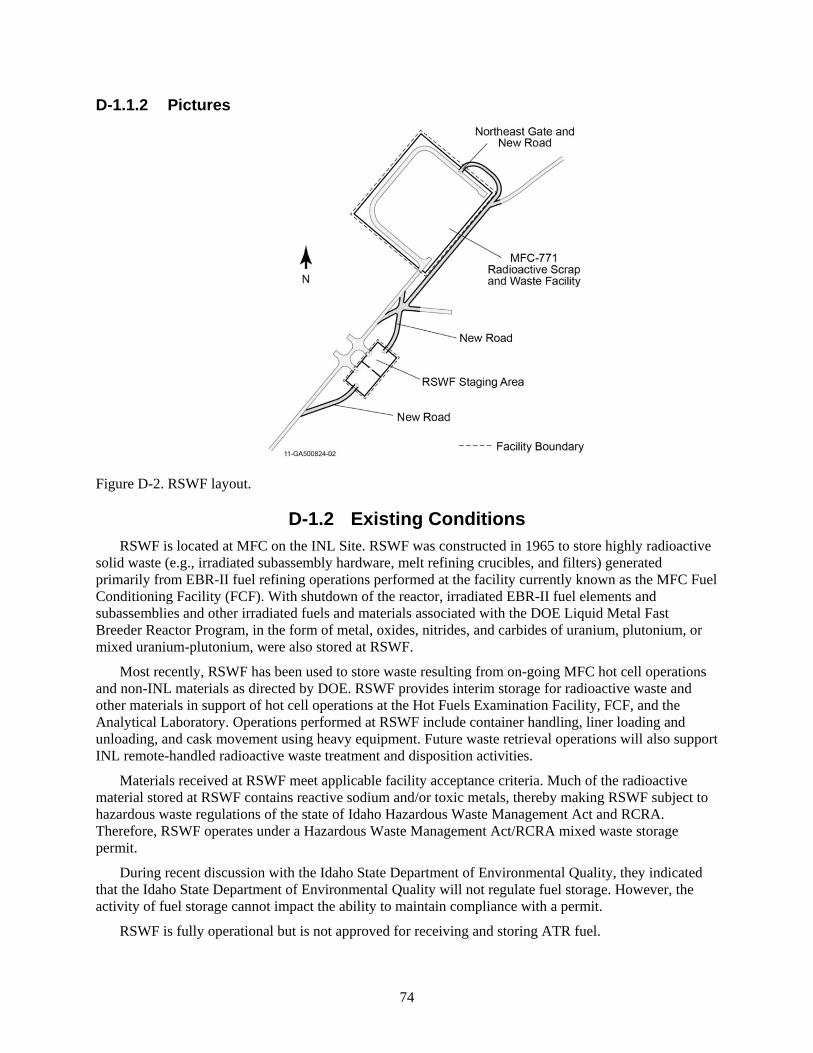
74
D-1.1.2 Pictures
Figure D-2. RSWF layout.
D-1.2 Existing Conditions RSWF is located at MFC on the INL Site. RSWF was constructed in 1965 to store highly radioactive
solid waste (e.g., irradiated subassembly hardware, melt refining crucibles, and filters) generated primarily from EBR-II fuel refining operations performed at the facility currently known as the MFC Fuel Conditioning Facility (FCF). With shutdown of the reactor, irradiated EBR-II fuel elements and subassemblies and other irradiated fuels and materials associated with the DOE Liquid Metal Fast Breeder Reactor Program, in the form of metal, oxides, nitrides, and carbides of uranium, plutonium, or mixed uranium-plutonium, were also stored at RSWF.
Most recently, RSWF has been used to store waste resulting from on-going MFC hot cell operations and non-INL materials as directed by DOE. RSWF provides interim storage for radioactive waste and other materials in support of hot cell operations at the Hot Fuels Examination Facility, FCF, and the Analytical Laboratory. Operations performed at RSWF include container handling, liner loading and unloading, and cask movement using heavy equipment. Future waste retrieval operations will also support INL remote-handled radioactive waste treatment and disposition activities.
Materials received at RSWF meet applicable facility acceptance criteria. Much of the radioactive material stored at RSWF contains reactive sodium and/or toxic metals, thereby making RSWF subject to hazardous waste regulations of the state of Idaho Hazardous Waste Management Act and RCRA. Therefore, RSWF operates under a Hazardous Waste Management Act/RCRA mixed waste storage permit.
During recent discussion with the Idaho State Department of Environmental Quality, they indicated that the Idaho State Department of Environmental Quality will not regulate fuel storage. However, the activity of fuel storage cannot impact the ability to maintain compliance with a permit.
RSWF is fully operational but is not approved for receiving and storing ATR fuel.

75
D-1.3 Capacity A significant portion of RSWF’s capacity is in use. Of the 16-in. diameter, 12-ft 4-in. length liners
identified for potential use with ATR SNF, some 264 are available. However, it is assumed that 183 liners that had waste/material removed would require new liner installation. New loaded liner monitoring requirements will need to be established. A compatible cask will be needed to transfer the dried, packaged ATR SNF from CPP-603 to RSWF.
D-1.4 Availability Total availability has not determined. A concern is that the facility has never been used to store the
quantity of fuel proposed for this option and no heat load calculations have been done to determine impact to configuration and stored, regulated waste in an adjacent storage location. Loaded liner monitoring requirements will need to be established that may drive design requirements such as vents. The number of liners is dependent on allowable canister loading.
D-2. ANALYSIS OF OPTION This option requires significant engineering analysis to evaluate transfer configuration from CPP-603,
the transfer cask, and interface with a storage liner. In addition, RSWF storage conditions such as heat load, seismic effects, radiation fields, and below-ground storage of aluminum fuel have not been evaluated. It is currently envisioned that transfers would occur under the authority of a transportation plan, rather than a revision to the safety analysis report, although accident and engineering analyses will still be needed. After definition of the storage configuration in the RSWF wells, liners, buckets, canisters, tooling, and miscellaneous hardware would be designed and performed. Identification of monitoring and security requirements, as well as development of procedures, would be required.
D-2.1 Description of the Facility RSWF, MFC-771, is a 388-ft wide and 448-ft long outdoor facility located at MFC. RSWF provides
interim storage for SNF, accountable material, and various radioactive waste.
The facility contains 27 rows of below-grade steel liners (right cylinders) of various sizes. Each row contains up to 50 liners on 6-ft centers, giving a potential total capacity of 1,350 storage locations. The majority of the liners currently in use at RSWF are 16, 24, and 26-in. outer diameter pipe. There are also 30-in. outer diameter liners (installed to serve as a contingency for any potential 16-in. or 24- in. overpack needs or lag storage), and 48 and 60-in. outer diameter liners that were fabricated and installed to accommodate non-standard waste packages. The liner lengths are 10 ft, 12 ft 4 in, 13 ft. 8 in., and 15 ft 1 in.
RSWF was constructed to store highly radioactive solid waste (e.g., irradiated subassembly hardware, melt refining crucibles, and filters) generated primarily from EBR-II fuel refining operations performed at the facility currently known as FCF. FCF went operational in 1965. With shutdown of the reactor, irradiated EBR-II fuel elements and subassemblies and other irradiated fuels and materials associated with the DOE Liquid Metal Fast Breeder Reactor Program (in the form of metal, oxides, nitrides, and carbides of uranium, plutonium, or mixed uranium-plutonium) were also stored at RSWF.
During the period from 1989 to 1997, RSWF underwent an upgrade to its cathodic protection system due to concerns about liner corrosion. The upgrade included installation of an impressed current cathodic protection system; replacement of all original passive cathodic protection equipment with new, impressed current cathodic protection; and relocation of material from original non-protected liners into new cathodically protected liners. The relocation effort resulted in the current containment configurations.
RSWF currently provides interim storage, retrieval, handling, and transfer capabilities for radioactive waste and other materials in support of MFC hot cell operations at the Hot Fuel Examination Facility,

76
FCF, and the Analytical Laboratory. These operations include research and development associated with spent fuel processing, waste form development and demonstration (e.g., metallic and ceramic forms), and other programs and operations as the mission at MFC continues to evolve. Future waste retrieval operations will also support INL remote-handled radioactive waste treatment and disposition activities. RSWF may also store other miscellaneous radioactive materials as directed by DOE.
Much of the radioactive material stored at RSWF contains reactive sodium and/or toxic metals, thereby making RSWF subject to the hazardous waste regulations of the state of Idaho’s Hazardous Waste Management Act and RCRA. As a result, RSWF operates under a Hazardous Waste Management Act/RCRA mixed waste storage permit.
The facility boundary is shown in Figure D-2. For hazard and accident analyses, the boundary is defined by the security fence surrounding the facility, excluding the personnel access trailer located on the west side of the security fence, and by the bottom of the liners. The following figures are pictures of the existing facility under construction and during waste placement operations.
Figure D-3. The facility, MFC-771, under construction, circa 1964.
Figure D-4. Waste package transfer to the facility, MFC-771.

77
Figure D-5. Waste package loading at the facility, MFC-771.
D-2.2 Barriers to Implementation • Underground storage of aluminum clad fuel, mixed with storage of sodium (i.e., combustible) fuel in
a RCRA-permitted area is potentially unacceptable to some stakeholders. There would be a need to update NEPA documentation, which opens the possibility of external stakeholder intervention, with the attendant schedule risk for ISA 2023 compliance.
• Engineering evaluations would be needed, the RCRA permit potentially revised, and the security posture revaluated and potentially revised.
• The thermal limits of ATR fuel may mean only a few elements could be stored in a standard Hot Fuel Examination Facility-5 can at RSWF. The EBR-II fuel was limited to 300 W/can and could withstand higher temperatures than the ATR fuel. This issue would need further study. Even at 10 elements per can (approximately 300 W), RSWF would not have the capacity to support receipt of the resulting 10 to 14 cans per year for the projected life of ATR and still provide support for MFC and receipt of EBR-II fuel from INTEC.
• The 18-in. diameter DOE standard canister cannot fit in the 16-in. diameter liners. Design of a canister and fuel bucket is a significant consideration. Using the same ATR eight bucket as CPP-603 and perhaps a canister could be designed to fit within a liner. However, the liner length and the height of a bucket with fuel limits the capacity to two ATR buckets (of eight elements each) per canister and one canister per liner for a total of 16 ATR elements per liner. This canister would clearly exceed the capacity of the ATR transfer cask with its maximum payload of eight (bare) ATR elements.
• The Hot Fuel Examination Facility canisters are the currently evaluated method for SNF storage at RSWF. DOE standard canisters are outside the bounds of the current safety basis and would require analyses. Storage of the DOE canister is only feasible in the 26-in. diameter liners, further limiting the storage space available.
• RSWF is currently operated by BEA as the INL maintenance and operating contractor. Under contract to DOE Idaho Operations Office, the Idaho Cleanup Project Core contractor Fluor Idaho, LLC is contracted to transfer 3,336 bottles of EBR-II SNF to MFC for treatment by the INL contractor at FCF, or for storage at RSWF, as determined by the INL contractor. An analysis is underway evaluating accelerated processing in FCF and maximizing storage in FCF may eliminate the need for future storage of EBR-II fuel in RSWF.

78
• RSWF availability is typically limited to 6 to 9 months of use per year due to weather and existing access limitations.
D-2.3 Assumptions and Strategies This option requires significant engineering analysis in the near term to evaluate RSWF storage
conditions such as heat load, seismic effects, radiation fields, and below-ground storage of aluminum fuel. It is currently envisioned that transfers would occur under the authority of a transportation plan, rather than a revision to the safety analysis report, although accident and engineering analyses will still be needed. After definition of storage configuration in the RSWF wells, design and fabrication of liners, buckets, canisters, tooling, and miscellaneous hardware would be performed. Identification of monitoring and security requirements and development of procedures would be required. Activities or actions deemed necessary to ensure project completion include the following:
• A signed memorandum of agreement detailing scope and roles and responsibilities between the parties with a schedule and budget
• A guaranteed funding rate for DOE-NE and DOE-EM commensurate with the necessary scope
• Approved safety basis strategy
• Approved security plan.
D-2.4 Packaging the Fuel Transfers from ATR and INTEC could be via the CPP-603 drying stations and could occur in the
ATR transfer cask. Buckets and canisters would have to be designed, procured, and fabricated. Detailed design studies have not been performed to determine the shipping configuration and transfer cask.
D-2.5 Regulatory Issues Revision of the RCRA permit requiring state of Idaho approval and evaluation to ensure NEPA
compliance are needed to allow storage and handling of ATR fuel at the RSWF. An EIS may be required because the existing 1995 EIS and record of decision favor consolidation of SNF at INTEC.
D-2.6 Cost (Capital and Operating) There is immediate need for funding to perform engineering analyses, revise the RCRA permit,
perform NEPA analysis, and update the safety basis, which may be substantial. Costs for security upgrades at RSWF may be substantial and may require a small capital asset project. Security operating and maintenance cost increases may also be substantial. No large capital costs are required until the end of interim storage, when capital expenditures for making the ATR SNF “road-ready” are likely, presumably at ISFF.
D-2.7 Risk • Risk of ATR fuel corrosion in an underground environment, with attendant release of fission products
if cladding is breached by the corrosion, is significant to this option. Monitoring can provide a gross measure of this corrosion. However, a sealed canister appropriately designed to keep excess moisture/water from getting to the fuel will be needed (the fuel will always have some residual moisture). Even so, outdoor underground storage at RSWF may be susceptible to water intrusion to the storage liners to the detriment of future SNF canister retrieval.
• The maximum temperature and decay heat of the elements will need evaluation to determine if passive cooling is adequate for the storage configuration and how much cooling is required to enable placement of the elements into these RSWF storage positions.
79
• The fuel may not be in a condition or package suitable for geologic disposal. It would not be in a DOE standard canister if the 16-in. liners are used.
• RSWF may not have the capacity to support ATR to the year 2050.
• Safety basis changes for the transfer may not be successful.
• Safety basis changes for RSWF may not be successful.
D-2.8 Complexity Moving fuel from one place to another within the INTEC environment is not complex. The
complexity comes from the need to package the material such that no excess moisture would propagate fuel corrosion. This effort is assumed to include drying, which would be accomplished by baking/drying, pulling a vacuum, purging, and back filling the canister with a gas. Coordination and prioritization of resource use at IFSF may be challenging. However, these fuel moves would not be much different from other existing fuel-handling operations. Movement in an outdoor environment adds risk and complexity.
D-2.9 Stakeholder Value This option uses existing facilities and systems to address some of the interim storage needs for ATR
fuel. However, this option relies on the drying and packaging capabilities at CPP-603, where throughput will be tightly constrained with the transfer of SNF out of CPP-666 in the same timeframe when the ATR canal runs out of space. This bottleneck could be further impacted by the availability of a suitable cask for transfer to RSWF and by decay heat restrictions for dry storage. Unacceptable delays are likely.
D-3. DISCRIMINATORS OF OPTION D-3.1 Meet the Capability Gap
This option appears not to meet the objective of putting ATR fuel into safe dry storage. Corrosion within the dry wells could possibly cause a problem that would not allow mission success.
D-3.1.1 Near Term This option would either put the 2023 ISA compliance date at risk or impact ATR operations.
D-3.1.2 Midterm This option may meet the needs for dry storage of a limited amount of ATR fuel.
D-3.1.3 Long Term This option does not meet the needs for storage of ATR fuels for the long-term. Space may be limited
for a suitable canister configuration; in addition, there is corrosion risk for long-term storage of ATR fuel in an underground environment.
D-3.2 Technical Complexity and Maturity of the Option • Thermal limits of ATR fuel may mean only a few elements could be stored in a standard Hot Fuel
Examination Facility 5 can at RSWF. The EBR-II fuel was limited to 300 W/can and could withstand higher temperatures than the ATR fuel. This issue would need further study. Even at 10 elements per can (approximately 300 W), RSWF would not have the capacity to support the resulting 10 to 14 cans per year for the projected life of ATR and still provide support for MFC and receipt of EBR-II fuel from INTEC.
• The 18-in. diameter DOE standard canister cannot fit in the 16-in. diameter liners.
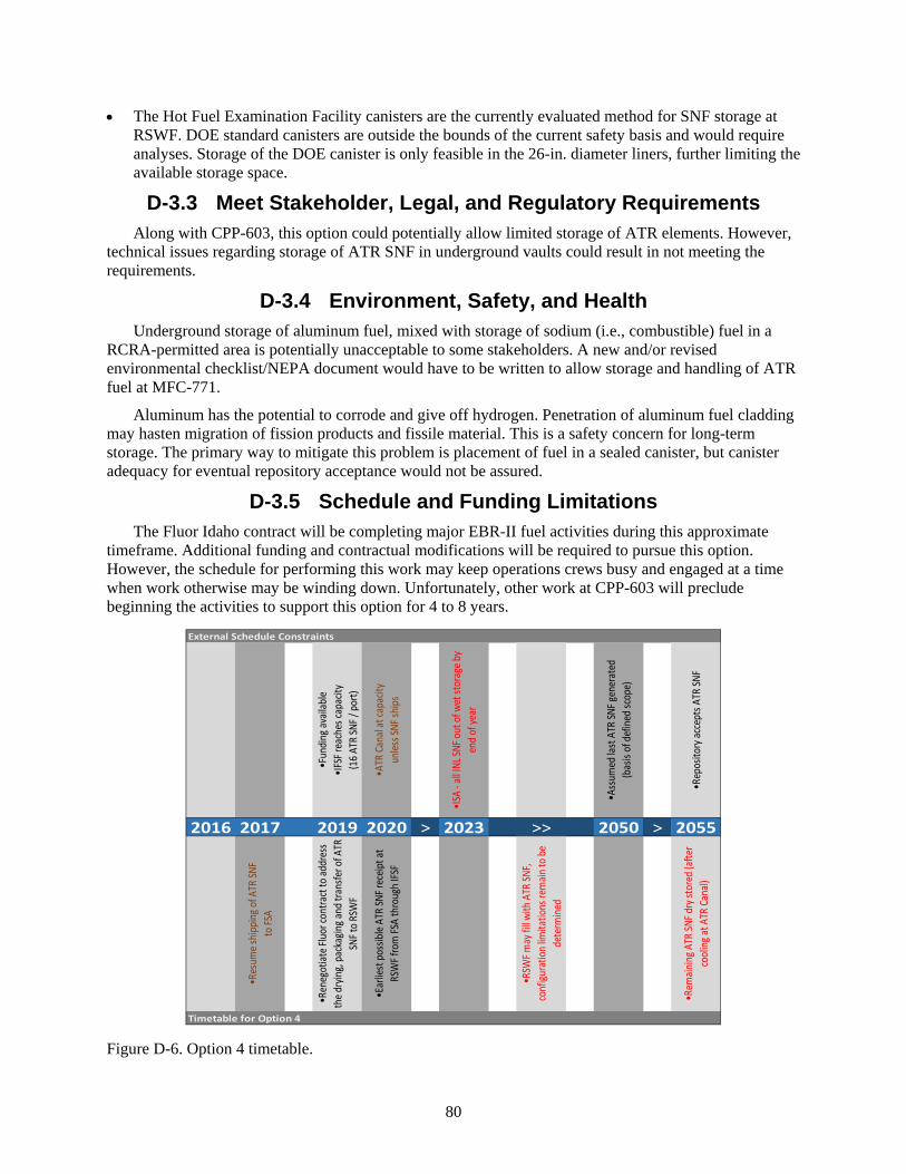
80
• The Hot Fuel Examination Facility canisters are the currently evaluated method for SNF storage at RSWF. DOE standard canisters are outside the bounds of the current safety basis and would require analyses. Storage of the DOE canister is only feasible in the 26-in. diameter liners, further limiting the available storage space.
D-3.3 Meet Stakeholder, Legal, and Regulatory Requirements Along with CPP-603, this option could potentially allow limited storage of ATR elements. However,
technical issues regarding storage of ATR SNF in underground vaults could result in not meeting the requirements.
D-3.4 Environment, Safety, and Health Underground storage of aluminum fuel, mixed with storage of sodium (i.e., combustible) fuel in a
RCRA-permitted area is potentially unacceptable to some stakeholders. A new and/or revised environmental checklist/NEPA document would have to be written to allow storage and handling of ATR fuel at MFC-771.
Aluminum has the potential to corrode and give off hydrogen. Penetration of aluminum fuel cladding may hasten migration of fission products and fissile material. This is a safety concern for long-term storage. The primary way to mitigate this problem is placement of fuel in a sealed canister, but canister adequacy for eventual repository acceptance would not be assured.
D-3.5 Schedule and Funding Limitations The Fluor Idaho contract will be completing major EBR-II fuel activities during this approximate
timeframe. Additional funding and contractual modifications will be required to pursue this option. However, the schedule for performing this work may keep operations crews busy and engaged at a time when work otherwise may be winding down. Unfortunately, other work at CPP-603 will preclude beginning the activities to support this option for 4 to 8 years.
Figure D-6. Option 4 timetable.
External Schedule Constraints
•Fun
ding
avail
able
•IFS
F rea
ches
capa
city
(16
ATR
SNF /
por
t)
•ATR
Can
al at
capa
city
unles
s SNF
ship
s
•ISA
- all
INL S
NF o
ut o
f wet
stor
age b
y en
d of
year
•Ass
umed
last
ATR
SNF g
ener
ated
(bas
is of
def
ined
scop
e)
•Rep
osito
ry ac
cept
s ATR
SNF
2016 2017 2019 2020 > 2023 >> 2050 > 2055
•Res
ume s
hipp
ing o
f ATR
SNF
to FS
A
•Ren
egot
iate F
luor
cont
ract
to ad
dres
s th
e dry
ing,
pac
kagin
g and
tran
sfer o
f ATR
SN
F to
RSW
F
•Ear
liest
pos
sible
ATR
SNF r
eceip
t at
RSW
F fro
m FS
A th
roug
h IFS
F
•RSW
F may
fill w
ith A
TR SN
F, co
nfigu
ratio
n lim
itatio
ns re
main
to b
e de
term
ined
•Rem
ainin
g ATR
SNF d
ry st
ored
(afte
r co
olin
g at A
TR C
anal)
Timetable for Option 4
81
D-3.6 Interfaces and Integration Requirements Ensure MFC and INTEC operations, environmental, and safety are onboard with the concepts of this
option. Obtain funding to start evaluations needed for drying and storing ATR fuel in MFC-771. Ensure consolidation of ATR fuels at CPP-603 is proceeding and anticipated to continue with this option. These items will need to be worked with Fluor, ATR, MFC, and DOE.
D-3.7 Safeguards and Security Prior to moving the fuel to MFC-771, an evaluation by safeguards and security would be required to
ensure the proper level of requirements were in place. Storing ATR SNF in MFC-771 may result in a significant increase from the current security posture, which would require significant additional capital expenditures and increases in security operating and maintenance costs.
D-3.8 Near-Term Cost There is immediate need for funding to perform engineering analyses, revise the RCRA permit,
perform NEPA analysis, and update the safety basis, which may be substantial. Costs for security upgrades at RSWF may be substantial and may require a small capital asset project. Security operating and maintenance cost increases may also be expensive. No large capital costs are required until the end of interim storage, when capital expenditures for making the ATR SNF “road-ready” are likely, presumably at ISFF.
D-3.9 Life-Cycle Cost Estimated total cost (including near-term cost and accumulated recurring costs) is in the mid-range.
Significant annual operating costs will be required to transfer the fuel from ATR to CPP-603 for drying prior to transport to RSWF. Use of a canister to store ATR fuel could keep the cost much lower than would otherwise be realized and should probably be pursued while packaging ATR fuel in an appropriate canister prior to placement in MFC-771. A package with the ability to be sealed purged and/or welded will be needed.
Drying and canning requirements would be upfront higher costs to ensure fuel was packaged in the appropriate configuration to mitigate the possibility of long-term corrosion.
D-4. RECOMMENDATION FOR OPTION Although this option could make use of existing facilities, existing transfer/transport systems, and
cost, technical concerns and costs of the canister design, precluding moisture from getting to the fuel, safety basis changes, permitting, extra handling (including drying), and no storage data for the ATR fuel, deters this option from being among the preferred options. The technical issues and packaging for this option must be detailed and very well analyzed, which could cause a significant rise in the cost. Handling and cost could very likely become significant due to the high possibility of extended corrosion. Increased safeguards and security issues could increase the security posture of RSWF and result in significant increases in capital expenditures and operations costs at RSWF. It would be preferred to look at and consider other options, allowing this to be on a last-case basis for implementation.

82
83
Appendix E
Option 5: Dry Storage of ATR SNF at UGFSF

84
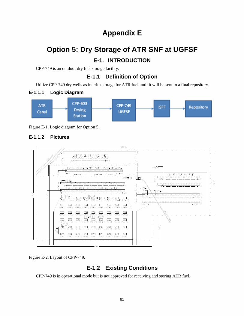
85
Appendix E
Option 5: Dry Storage of ATR SNF at UGFSF E-1. INTRODUCTION
CPP-749 is an outdoor dry fuel storage facility.
E-1.1 Definition of Option Utilize CPP-749 dry wells as interim storage for ATR fuel until it will be sent to a final repository.
E-1.1.1 Logic Diagram
Figure E-1. Logic diagram for Option 5.
E-1.1.2 Pictures
Figure E-2. Layout of CPP-749.
E-1.2 Existing Conditions CPP-749 is in operational mode but is not approved for receiving and storing ATR fuel.
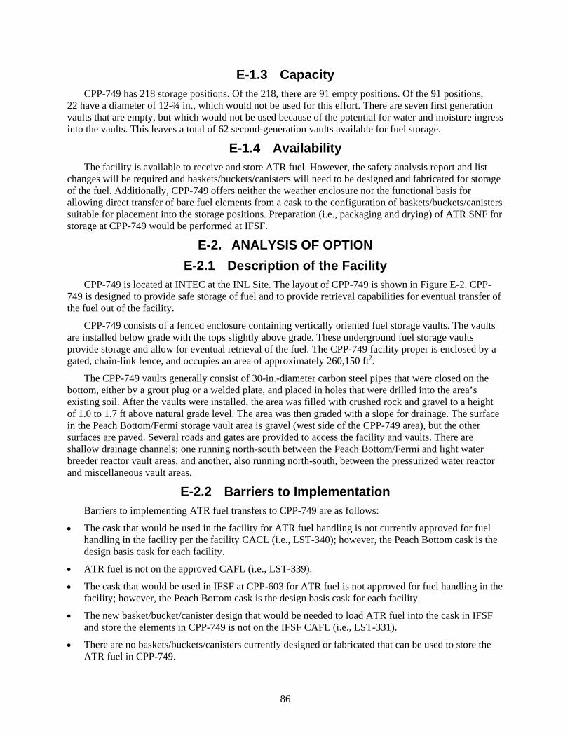
86
E-1.3 Capacity CPP-749 has 218 storage positions. Of the 218, there are 91 empty positions. Of the 91 positions,
22 have a diameter of 12-¾ in., which would not be used for this effort. There are seven first generation vaults that are empty, but which would not be used because of the potential for water and moisture ingress into the vaults. This leaves a total of 62 second-generation vaults available for fuel storage.
E-1.4 Availability The facility is available to receive and store ATR fuel. However, the safety analysis report and list
changes will be required and baskets/buckets/canisters will need to be designed and fabricated for storage of the fuel. Additionally, CPP-749 offers neither the weather enclosure nor the functional basis for allowing direct transfer of bare fuel elements from a cask to the configuration of baskets/buckets/canisters suitable for placement into the storage positions. Preparation (i.e., packaging and drying) of ATR SNF for storage at CPP-749 would be performed at IFSF.
E-2. ANALYSIS OF OPTION E-2.1 Description of the Facility
CPP-749 is located at INTEC at the INL Site. The layout of CPP-749 is shown in Figure E-2. CPP-749 is designed to provide safe storage of fuel and to provide retrieval capabilities for eventual transfer of the fuel out of the facility.
CPP-749 consists of a fenced enclosure containing vertically oriented fuel storage vaults. The vaults are installed below grade with the tops slightly above grade. These underground fuel storage vaults provide storage and allow for eventual retrieval of the fuel. The CPP-749 facility proper is enclosed by a gated, chain-link fence, and occupies an area of approximately 260,150 ft2.
The CPP-749 vaults generally consist of 30-in.-diameter carbon steel pipes that were closed on the bottom, either by a grout plug or a welded plate, and placed in holes that were drilled into the area’s existing soil. After the vaults were installed, the area was filled with crushed rock and gravel to a height of 1.0 to 1.7 ft above natural grade level. The area was then graded with a slope for drainage. The surface in the Peach Bottom/Fermi storage vault area is gravel (west side of the CPP-749 area), but the other surfaces are paved. Several roads and gates are provided to access the facility and vaults. There are shallow drainage channels; one running north-south between the Peach Bottom/Fermi and light water breeder reactor vault areas, and another, also running north-south, between the pressurized water reactor and miscellaneous vault areas.
E-2.2 Barriers to Implementation Barriers to implementing ATR fuel transfers to CPP-749 are as follows:
• The cask that would be used in the facility for ATR fuel handling is not currently approved for fuel handling in the facility per the facility CACL (i.e., LST-340); however, the Peach Bottom cask is the design basis cask for each facility.
• ATR fuel is not on the approved CAFL (i.e., LST-339).
• The cask that would be used in IFSF at CPP-603 for ATR fuel is not approved for fuel handling in the facility; however, the Peach Bottom cask is the design basis cask for each facility.
• The new basket/bucket/canister design that would be needed to load ATR fuel into the cask in IFSF and store the elements in CPP-749 is not on the IFSF CAFL (i.e., LST-331).
• There are no baskets/buckets/canisters currently designed or fabricated that can be used to store the ATR fuel in CPP-749.
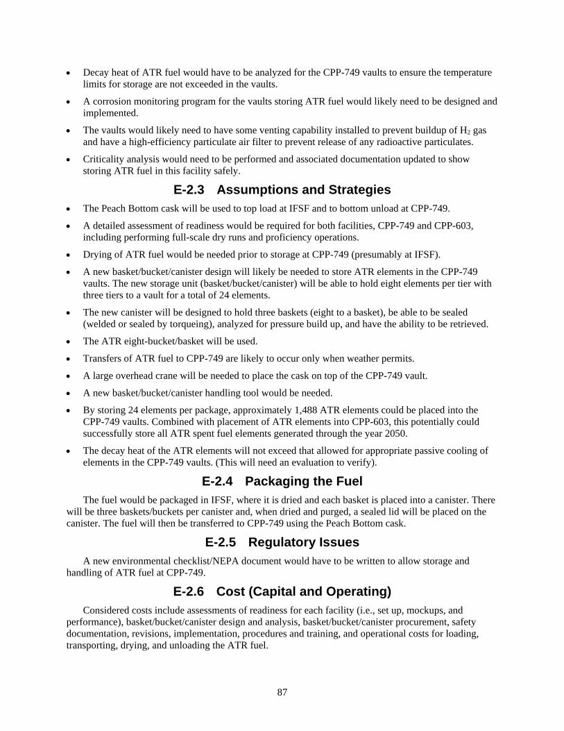
87
• Decay heat of ATR fuel would have to be analyzed for the CPP-749 vaults to ensure the temperature limits for storage are not exceeded in the vaults.
• A corrosion monitoring program for the vaults storing ATR fuel would likely need to be designed and implemented.
• The vaults would likely need to have some venting capability installed to prevent buildup of H2 gas and have a high-efficiency particulate air filter to prevent release of any radioactive particulates.
• Criticality analysis would need to be performed and associated documentation updated to show storing ATR fuel in this facility safely.
E-2.3 Assumptions and Strategies • The Peach Bottom cask will be used to top load at IFSF and to bottom unload at CPP-749.
• A detailed assessment of readiness would be required for both facilities, CPP-749 and CPP-603, including performing full-scale dry runs and proficiency operations.
• Drying of ATR fuel would be needed prior to storage at CPP-749 (presumably at IFSF).
• A new basket/bucket/canister design will likely be needed to store ATR elements in the CPP-749 vaults. The new storage unit (basket/bucket/canister) will be able to hold eight elements per tier with three tiers to a vault for a total of 24 elements.
• The new canister will be designed to hold three baskets (eight to a basket), be able to be sealed (welded or sealed by torqueing), analyzed for pressure build up, and have the ability to be retrieved.
• The ATR eight-bucket/basket will be used.
• Transfers of ATR fuel to CPP-749 are likely to occur only when weather permits.
• A large overhead crane will be needed to place the cask on top of the CPP-749 vault.
• A new basket/bucket/canister handling tool would be needed.
• By storing 24 elements per package, approximately 1,488 ATR elements could be placed into the CPP-749 vaults. Combined with placement of ATR elements into CPP-603, this potentially could successfully store all ATR spent fuel elements generated through the year 2050.
• The decay heat of the ATR elements will not exceed that allowed for appropriate passive cooling of elements in the CPP-749 vaults. (This will need an evaluation to verify).
E-2.4 Packaging the Fuel The fuel would be packaged in IFSF, where it is dried and each basket is placed into a canister. There
will be three baskets/buckets per canister and, when dried and purged, a sealed lid will be placed on the canister. The fuel will then be transferred to CPP-749 using the Peach Bottom cask.
E-2.5 Regulatory Issues A new environmental checklist/NEPA document would have to be written to allow storage and
handling of ATR fuel at CPP-749.
E-2.6 Cost (Capital and Operating) Considered costs include assessments of readiness for each facility (i.e., set up, mockups, and
performance), basket/bucket/canister design and analysis, basket/bucket/canister procurement, safety documentation, revisions, implementation, procedures and training, and operational costs for loading, transporting, drying, and unloading the ATR fuel.

88
E-2.7 Risk The risk of having corrosion of ATR fuel in an underground environment, with attendant release of
fission products if cladding is breached by the corrosion, is considered to be the biggest risk to this option. This risk can be mitigated if the basket/bucket/canister that holds the fuel is appropriately designed to keep excess moisture/water from getting to the fuel (the fuel will already have some residual moisture). The maximum temperature and decay heat of the elements will need to be evaluated to determine if passive cooling is adequate in the CPP-749 vaults and how much cooling is required to enable placement of the elements into these vaults.
E-2.8 Complexity Just moving fuel from one place to another is not complex within the INTEC environment. The
complexity comes from the need to package the material so no excess moisture would propagate corrosion of the fuel. This effort of drying would be accomplished by baking/drying, pulling a vacuum, purging, and back filling the canister with a gas. Coordination and prioritization of resource use at IFSF may be challenging. However, these fuel moves would not be much different from other existing fuel handling operations. Design of storage containers is required for almost all of the other options as well as this one.
E-2.9 Stakeholder Value This option utilizes existing facilities and systems to address some of the interim storage needs for
ATR fuel (through the year 2050 and perhaps beyond). An added possible benefit is that, if done correctly (i.e., up front), the fuel could be packaged in a configuration that would allow fuel to be loaded into a standard SNF canister directly out of the CPP-749 storage vaults.
E-3. DISCRIMINATORS OF OPTION E-3.1 Meet the Capability Gap
This option appears to meet the objective of putting ATR fuel into dry storage. Although, corrosion is a problem that may cause an issue in the future that could alter the objectiveness of the option. This option provides a potential solution for storage of ATR SNF through the year 2050 (and perhaps beyond). Corrosion with the dry wells could possibly cause a problem that would not allow mission success.
E-3.1.1 Near Term This option assumes that CPP-603 meets the needs for ATR storage in the near-term.
E-3.1.2 Midterm The combination of using CPP-603 and this option should meet the needs for storage of ATR fuel.
E-3.1.3 Long Term This option may meet the needs for storage of ATR fuel for the long term. However, it must be
realized that there are no data to support the long-term storage of ATR fuel in an underground environment. Because of this, long-term storage in the CPP-749 vaults may not be a preferred option.
E-3.2 Technical Complexity and Maturity of the Option Technically, the option of moving and storing ATR fuel in CPP-749 is not highly complex. The real
complexity comes about in how the fuel is dried or kept dry in an underground environment.
This option will require drying and repackaging of the ATR fuel prior to being placed into CPP-749. In order to prepare the ATR fuel for storage in the vaults, it will have to be packaged differently than if it were to be stored in CPP-603. There would be a canister with three buckets of eight elements to a bucket

89
to be placed in each vault. Prior to putting the lid on the canister, the fuel will be dried, a lid with sealing capabilities installed, a vacuum taken, and then the canister will be backfilled with gas.
Extra fuel handling iteration would be required to get ATR SNF ready to store. Also, because it is an outdoor facility, fuel transfer to (or from) a vault at CPP-749 is dependent on weather conditions.
E-3.3 Meet Stakeholder, Legal, and Regulatory Requirements Along with CPP-603, this option allows storage of all ATR elements through about the year 2050,
which places all SNF into dry storage in accordance with ISA, which requires all SNF be out of wet storage. It does not meet the ISA requirement for getting all SNF out of the state by the year 2035.
E-3.4 Environment, Safety, and Health A new environmental checklist/NEPA document would have to be written to allow storage and
handling of ATR fuel at CPP-749.
Aluminum has the potential to corrode and give off hydrogen. Penetration of the aluminum fuel cladding may hasten migration of fission products and fissile material. This is a safety concern for long-term storage. The primary way to mitigate this problem is placement of the fuel in a sealed canister. However, canister adequacy for eventual repository acceptance would not be assured.
E-3.5 Schedule and Funding Limitations The Fluor Idaho contract will complete major fuel activities during approximately this same
timeframe. Additional funding and contractual modifications will be required to pursue this option. However, the schedule for performing this work may work well to keep operations crews busy and engaged at a time when work otherwise may be winding down.
Unfortunately, other work at CPP-603 will preclude beginning activities to support this option for 4 to 8 years
INTEC operations and safety need to be onboard with the concepts of this option. Funding must be obtained to start evaluations needed for drying and storing ATR fuel in CPP-749. Consolidation of ATR fuels at CPP-603 is proceeding and anticipated to continue with this option.
90
Figure E-3. Option 5 timetable.
E-3.6 Interfaces and Integration Requirements These items will need to be worked with Fluor, ATR, and DOE.
E-3.7 Safeguards and Security Prior to moving the fuel to CPP-749, an evaluation by safeguards and security would be required to
ensure the proper level of requirements were in place.
E-3.8 Near-Term Cost Relative to the other evaluated options, the near-term cost of this option is low given the following:
• A line item capital project will not be required.
• Initial investment includes basket/bucket/canister configuration development and analysis, as well as development and review of handling processes to receive, dry, package and store the fuel.
• The NEPA evaluation was not included in this estimate; if a NEPA checklist would be sufficient, this evaluation cost would be negligible.
External Schedule Constraints
•Fun
ding
ava
ilabl
e•I
FSF
reac
hes c
apac
ity(1
6 AT
R SN
F / p
ort)
•ATR
Can
al a
t cap
acity
unle
ss S
NF sh
ips
•ISA
- al
l INL
SNF
out
of w
et st
orag
e by
en
d of
yea
r
•Ass
umed
last
ATR
SNF
gen
erat
ed(b
asis
of d
efin
ed sc
ope)
•Rep
osito
ry a
ccep
ts A
TR S
NF
2016 2017 2019 2020 > 2023 >> 2034 >> 2050 > 2055
•Res
ume
ship
ping
of A
TR S
NFto
FSA
•Ren
egot
iate
Flu
or co
ntra
ct to
pro
mot
e ef
ficie
nt im
plem
enta
tion
•Dev
elop
cani
ster
des
ign
& sa
fety
case
•Ear
liest
pos
sible
ATR
SNF
rece
ipt a
tCP
P-74
9 fro
m F
SA th
roug
h IF
SF
•CPP
-749
fills
with
ATR
SNF
, mus
t fin
d ot
her s
tora
ge (2
4 AT
R SN
F / p
ort a
t IFS
F or
spac
e at
ISFF
?)
•Rem
aini
ng A
TR S
NF d
ry st
ored
(afte
r co
olin
g at
ATR
Can
al)
Timetable for Option 5
91
E-3.9 Life-Cycle Cost This option is low cost overall. Life-cycle cost includes both the initial costs identified and the
recurring costs accumulated over the life of the ATR SNF.
E-3.9.1 Recurring Costs • Drying and canning requirements would be upfront costs for ensuring the fuel is packaged in the
appropriate configuration to mitigate the possibility of long-term corrosion.
• A package with the ability to be sealed, purged, and/or welded will be needed.
E-4. RECOMMENDATION FOR OPTION Although this option offers favorable use of existing facilities, use of existing transfer/transport
systems, and overall cost, consolidation of Peach Bottom fuel at CPP-749 to open up space for ATR fuel at IFSF is considered to be better use of this facility space. Concerns and costs of the canister design, preventing moisture from getting to the fuel, safety basis changes, extra handling and drying (including logistical challenges for throughput capacity at CPP-603), and the lack of storage precedent for ATR fuel at CPP-749, preclude the endorsement of this option.

92
93
Appendix F
Option 6: Dry Storage of ATR SNF at IFSF

94

95
Appendix F
Option 6: Dry Storage of ATR SNF at IFSF F-1. INTRODUCTION
CPP-603, IFSF, has 636 storage locations that have several types of fuel, including ATR fuel. The ATR fuel currently resides in 126 canisters in IFSF, with one canister per storage location. Another 63 positions are planned to receive 1,000 ATR SNF elements from FSA. The existing configuration holds 16 ATR SNF elements (two buckets of eight elements each) per canister in CPP-603. This option optimizes use of the space already allocated for ATR fuel in this facility by reconfiguring canister loading to place 24 ATR elements in each storage location.
F-1.1 Definition of Option
Transfer ATR fuel from the ATR canal to CPP-603 for interim storage, reconfiguring from 16 ATR SNF per canister to 24 ATR SNF per canister to optimize use of the locations available to store ATR fuel.
F-1.1.1 Logic Diagram
Figure F-1. Logic diagram for Option 6.

96
F-1.1.2 Pictures
Figure F-2. Layout of CPP-603.
F-1.2 Existing Conditions
CPP-603 is in operations mode and is approved for receiving and storing ATR fuel.
F-1.3 Capacity
CPP-603 has a total of 636 canister storage positions that are used to store 23 different types of fuel. ATR fuel takes up 126 of those. Currently, 82 positions are open, with 63 of those to be used for ATR fuel being transferred from CPP-666; this leaves 19 open for other types of fuel (e.g., TRIGA, Sandia).
F-1.4 Availability
Fuel can be transferred from CPP-666 to CPP-603. No revisions to the safety basis would be needed to allow ATR fuel into either facility. Some changes would need to be made to accommodate a new basket/bucket suitable for storage of 24 ATR SNF elements per storage location in IFSF and to accept the ATR transfer cask directly at CPP-603 or the High-Load Charger at the ATR canal.
F-2. ANALYSIS OF OPTION
F-2.1 Description of the Facility
IFSF is located at INTEC. Construction of IFSF proper was completed in December 1974. IFSF was designed to provide safe, interim, fuel storage pending retrieval of the stored fuel for final disposal. To
97
meet this goal, the main operations performed in IFSF include receiving nuclear fuels from other facilities, repackaging and conditioning fuels for interim storage, safely storing fuels, storing fuel-loaded storage casks on an interim basis, and packaging fuels for removal from the facility (transfer).
IFSF is located in CPP-603, which is in the southwest corner of INTEC. CPP-603 consists of IFSF, the Basin Facility (closed and grouted), and common truck bays with overhead crane systems. IFSF functional areas include (1) the cask receiving area (including east/west truck bay, north/south truck bay, and truck ramp), (2) the cask transfer pit and PCS, (3) the fuel-handling cave, (4) the fuel storage area, (5) the crane maintenance area, (6) control and instrument rooms, (7) miscellaneous support areas, and (8) fuel storage basin interfaces. The miscellaneous support areas include a standby generator room (inactive); HVAC equipment area (CPP-2710); and an access building (CPP-626) that is not considered part of IFSF (see Figure F-2 for the facility layout). In the cask receiving area, fuel shipping packages are received and prepared for receipt into the IFSF fuel-handling cave or prepared for shipment out of IFSF. Additionally, the cask receiving area is used for storage of shipping packages and storage of miscellaneous tools and equipment. In accordance with cask-specific analysis, the truck bays are used for interim storage of fuel-loaded storage casks. Operations and activities may be conducted in the various functional areas of the facility to test operational evolutions, to test equipment and tool function, and to perform dry runs.
Only those fuels specified in a CAFL may be received, handled, and stored at IFSF and only those casks on the CACL may be loaded, unloaded, or stored at IFSF. In both cases, the activities are performed in accordance with the criticality safety requirements contained in the criticality safety controls list. The CAFL and CACL are derived from a technical basis that is maintained in existing files and includes fuel and cask data and analyses. Fuel and shipping packages are moved into and out of the fuel-handling cave via the cask transfer pit. During receipt, a fuel package is placed on the cask transfer car with the crane. Then the cask transfer car is moved under the fuel-handling cave wall into the fuel-handling cave. The PCS covers the cask transfer pit in the cask receiving area for contamination confinement. Venting and decontamination of the cask may be conducted in the PCS. A sump and sump pump are located in the bottom of the cask transfer pit to collect and pump out any water that might drain from the fuel-handling cave, truck ramp, or fuel storage area. Liquid waste transferred from the IFSF cask transfer pit sump may be placed into a standby tanker truck or other temporary tank(s).
Operations performed in the fuel-handling cave include remote handling of cask lids, handling of fuel packages, examining fuel, examining a fuel-loaded cask and its contents, and repackaging of fuel for storage or shipment. Some nuclear fuels received at IFSF require treatment in the FCS, which was formerly known as the fuel canning station. The FCS is located in the fuel-handling cave.
The fuel storage area contains a storage rack that provides spacing and support for fuel storage canisters. The storage rack maintains a staggered spacing of canisters for criticality purposes. Fuel is moved into the fuel storage area in fuel storage canisters through the shuttle bin. The canister is placed in its designated position in the storage rack using a crane.
F-2.2 Barriers to Implementation
The following are barriers to implementing fuel transfers to CPP-603:
• Coordination of resources will be needed to accommodate implementation of this new configuration, transfer of fuel out of FSA before the end of 2023, and receive newly generated ATR SNF from the ATR canal on a schedule that both provides sufficient cooling for dry storage and also enables uninterrupted ATR operation.
• A new basket/bucket design would be needed to accommodate the new ATR fuel configuration.
• The cask (i.e., ATR transfer cask) that would be used to receive fuel directly from the ATR canal is not currently approved for fuel handling in IFSF. This cask is similar to the High-Load Charger
98
(which is approved), but some changes and review would be needed. Alternately, the review and changes could be implemented at ATR to allow acceptance and loading of High-Load Charger at the ATR canal.
F-2.3 Assumptions and Strategies
• Cooling requirements will need to be revised. Currently, ATR fuel decay heat cannot exceed 270 W per canister as specified by CPP-603 analysis; this is a constraint generally satisfied after 6 years of cooling. ATR canal capacity cannot accommodate 6 years of post-service fuel. However, preliminary analysis indicates that CPP-603 could now safely store ATR SNF canisters producing over 1,000 W of heat, a constraint both satisfied by approximately 4 years out of reactor and achievable with existing ATR canal capacity.
• A new basket/bucket design will be needed to store ATR elements in the 24 element per canister configuration.
• Reconfiguring ATR elements stored at IFSF allows the available (126 + 63 =) 189 storage locations to accept another (24*189 - 16*189 = 4536 - 3024 =) 1,512 ATR elements. The projected effects of fuel reconfiguration, the ATR SNF generation rate, and the anticipated fuel transfers are shown in Table F-1.
• Transfer of ATR SNF from FSA to IFSF should be planned for efficient implementation to avoid unnecessary fuel handling.
F-2.4 Packaging the Fuel
The 16 elements in a canister at CPP-603 will be repackaged from two baskets, with each holding eight elements to a canister of 24 elements comprised of a basket of eight elements and a basket of 16 elements. Later, shipments of ATR fuel should go directly from ATR to IFSF.
F-2.5 Regulatory Issues
A revision may be needed to update the environmental checklist/NEPA document; however, IFSF already houses ATR fuel.
F-2.6 Cost (Capital and Operating)
Considered costs include assessments of readiness (i.e., setup, mockups, and performance), basket/bucket design and analysis, basket/bucket/canister procurement, safety documentation, revisions, implementation, procedures and training, and operational costs for loading, unloading, drying, and reconfiguring ATR fuel. This option provides efficient use of an existing facility.
F-2.7 Risk
There is risk in handling the fuel, but the operations required to implement this option are not new for this facility.
F-2.8 Complexity
This option is not really that different in complexity than the other options being evaluated. These fuel moves would not be much different than any other fuel move. Design of a storage containers is required for just about all of the other options as well. Drying will likely be needed for most, if not all, of the options.
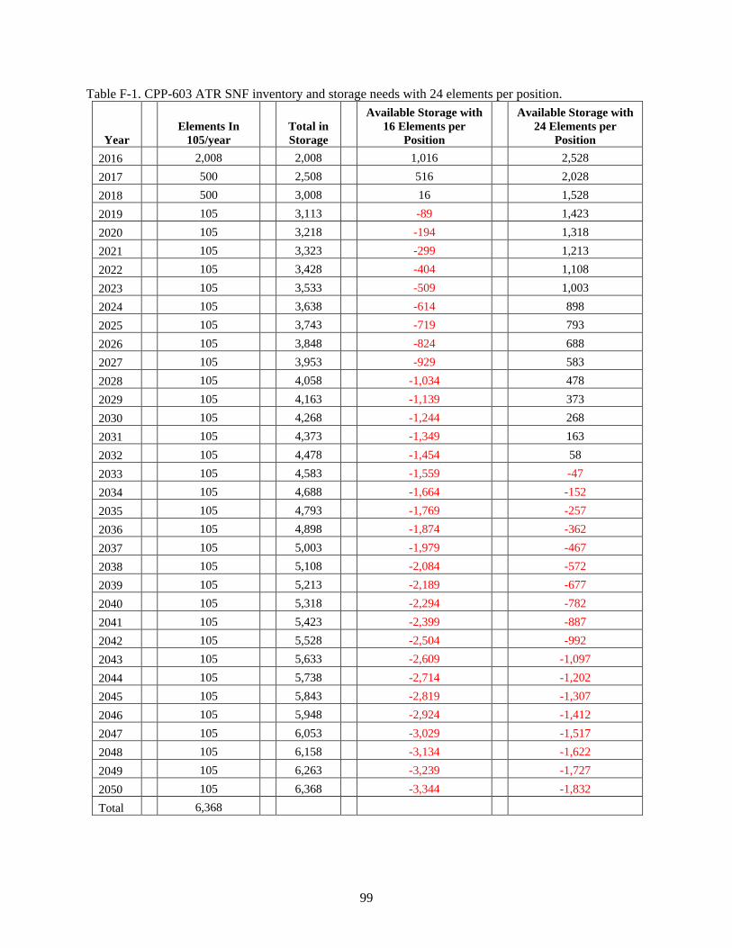
99
Table F-1. CPP-603 ATR SNF inventory and storage needs with 24 elements per position.
Year Elements In
105/year Total in Storage
Available Storage with 16 Elements per
Position
Available Storage with 24 Elements per
Position 2016 2,008
2,008
1,016 2,528
2017 500
2,508
516 2,028 2018 500
3,008
16 1,528
2019 105
3,113
-89 1,423 2020 105
3,218
-194 1,318
2021 105
3,323
-299 1,213 2022 105
3,428
-404 1,108
2023 105
3,533
-509 1,003 2024 105
3,638
-614 898
2025 105
3,743
-719 793 2026 105
3,848
-824 688
2027 105
3,953
-929 583 2028 105
4,058
-1,034 478
2029 105
4,163
-1,139 373 2030 105
4,268
-1,244 268
2031 105
4,373
-1,349 163 2032 105
4,478
-1,454 58
2033 105
4,583
-1,559 -47 2034 105
4,688
-1,664 -152
2035 105
4,793
-1,769 -257 2036 105
4,898
-1,874 -362
2037 105
5,003
-1,979 -467 2038 105
5,108
-2,084 -572
2039 105
5,213
-2,189 -677 2040 105
5,318
-2,294 -782
2041 105
5,423
-2,399 -887 2042 105
5,528
-2,504 -992
2043 105
5,633
-2,609 -1,097 2044 105
5,738
-2,714 -1,202
2045 105
5,843
-2,819 -1,307 2046 105
5,948
-2,924 -1,412
2047 105
6,053
-3,029 -1,517 2048 105
6,158
-3,134 -1,622
2049 105
6,263
-3,239 -1,727 2050 105
6,368
-3,344 -1,832
Total 6,368
100
F-2.9 Stakeholder Value
This option utilizes an existing facility and its handling capabilities to increase capacity by reconfiguring the basket loading within the allocated storage space. This option meets near-term and midterm dry storage objectives, but does not quite accommodate the full inventory of ATR SNF over the projected period.
F-3. DISCRIMINATORS OF OPTION
F-3.1 Meet the Capability Gap
This option provides a potential solution to storage of ATR spent fuel though the year 2034. As illustrated in Table F-1, CPP-603 is filled to capacity at 24 elements per position in the year 2033. The ATR canal would likely run out of space approximately a year later unless other accommodations are made.
The option falls short of the objective of putting ATR SNF into dry storage over the projected period through the year 2050.
F-3.1.1 Near Term
This option assumes that CPP-603 meets the needs for ATR storage in the near-term (1,000 element transfer from CPP-666). Without reprioritization, other work at CPP-603 will preclude beginning the activities to support this option for 2 to 4 years.
F-3.1.2 Midterm
Using the 189 positions allocated for ATR SNF at CPP-603 and consolidation (16 to 24 elements per position), this option should meet the needs for storage of ATR fuel until approximately the year 2034, when both the ATR canal and CPP-603 would be filled to capacity.
F-3.1.3 Long Term
As a stand-alone option, this will not meet the needs for storage of ATR SNF generated through the year 2050.
F-3.2 Technical Complexity and Maturity of the Option
Technically, the option is not highly complex but it requires several interfaces and agreements between DOE-NE and EM that have not been in place in the past. Packaging may be very similar or nearly the same as currently used.
The highest level of technical risk for this option is the actual handling of fuel. The main risk to success of this option is competing use of IFSF during the period when FSA works to vacate wet storage and ATR canal space is most tightly constrained.
F-3.3 Meet Stakeholder, Legal, and Regulatory Requirements
Along with CPP-603, this option allows storage of all ATR elements through about the year 2050, which places all SNF into dry storage per ISA, which requires all spent fuel be out of wet storage by 2023. It does not meet the ISA requirement for getting all SNF out of the state by the year 2035.

101
F-3.4 Environment, Safety, and Health
A new environmental checklist/NEPA document may be needed. This option poses no adverse safety concerns because all operations are similar (or the same) as operations currently performed (or were performed in the recent past).
F-3.5 Schedule and Funding Limitations
The timing for making this option viable is most likely to start about 2 to 4 years from now. The Fluor Idaho contract will be completing the major fuel activities about this same timeframe. The schedule for performing this work may prove well to keep operations crews busy and engaged at a time when work otherwise may be winding down. Additional funding and contractual modifications will be required.
Other work that is schedule to be performed at CPP-603 will preclude the beginning of the activities to support this option for 2 to 4 years.
Figure F-2. Option 6 timetable.
F-3.6 Interfaces and Integration Requirements
Interface and integration requirements/agreements would have to be evaluated and agreed upon by Fluor, BEA, and DOE-NE and EM.
External Schedule Constraints
•Fun
ding
ava
ilabl
e•I
FSF
reac
hes c
apac
ity(1
6 AT
R SN
F / p
ort)
•ATR
Can
al a
t cap
acity
unle
ss S
NF sh
ips
•ISA
- al
l INL
SNF
out
of w
et st
orag
e by
en
d of
yea
r
•ATR
Can
al a
t cap
acity
unle
ss S
NF sh
ips
•Ass
umed
last
ATR
SNF
gen
erat
ed(b
asis
of d
efin
ed sc
ope)
•Rep
osito
ry a
ccep
ts A
TR S
NF
2016 2017 2019 2020 > 2023 >> 2034 >> 2050 > 2055
•Res
ume
ship
ping
of A
TR S
NFto
CPP
-666
•Ren
egot
iate
Flu
or co
ntra
ct to
pro
mot
e ef
ficie
nt im
plem
enta
tion
•Dev
elop
bas
ket d
esig
n &
safe
ty ca
se
•Beg
in re
pack
ing
ATR
SNF
in IF
SF(2
4 AT
R SN
F / p
ort)
•IFS
F re
ache
s cap
acity
(24
ATR
SNF
/ por
t)•I
mpa
cts A
TR o
pera
tion
Timetable for Option 6

102
F-3.7 Safeguards and Security
No changes in safeguards and security are needed.
F-3.8 Near-Term Cost
This option requires only a relatively low near-term cost that considers the following:
• No line item capital projects are needed
• Development costs (including cask handling and new canister design) are included
• NEPA compliance – environmental checklist may be needed, but the expense and impact should be minimal because actions are simply optimizing use of existing capacity within existing facilities.
F-3.9 Life-Cycle Cost
This option is low cost overall. Life-cycle cost includes both the initial costs identified as near-term cost and the recurring costs accumulated over the life of the ATR SNF.
F-3.9.1 Recurring Costs
• Annual facility maintenance costs over 33 years of operation (i.e., 2022 through 2055)
• Bucket/basket purchase (for 16 ATR elements loading)
• Transfer operations (repackaging as new fuel is received).
Costs are expected to be lower than most other options being considered.
F-4. RECOMMENDATION FOR OPTION
This option is favorable because of its simplicity, use of existing facilities, use of existing transfer/transport systems, and relatively low cost (considering all other options). However, the space recovered with ATR SNF reconfiguration as a stand-alone option is insufficient to meet ATR needs beyond the year 2034.
103
Appendix G
Option 7: Consolidate and Optimize INTEC Dry Storage: Transfer Peach Bottom SNF from IFSF to UGFSF and Transfer ATR SNF from FSA and ATR
Canal to IFSF

104

105
Appendix G
Option 7: Consolidate and Optimize INTEC Dry Storage: Transfer Peach Bottom SNF from IFSF to UGFSF and Transfer ATR SNF from
FSA and ATR Canal to IFSF G-1. INTRODUCTION
CPP-603, IFSF, has 636 storage wells that have several types of fuel, including ATR and Peach Bottom. The ATR fuel resides in 126 canisters in IFSF. The Peach Bottom fuel (Core 2) resides in 71 canisters at IFSF. The Peach Bottom fuel was cut from 144 in. to 126 in. (i.e., the top 18-in. were removed) to facilitate storage in a canister. There are 12 elements (open storage, no bucket) per canister in CPP-603. Repackaging Peach Bottom into buckets with 18 elements per package and transferring to CPP-749 with the other Peach Bottom Fuel (Core 1) would free up 71 positions that could be used to store ATR fuel. As a part of this option, it may be prudent to look at what it would take to place the elements into a package that would allow direct transfer into a standardized canister for shipment to a long-term storage facility.
G-1.1 Definition of Option
Transfer Peach Bottom fuel from IFSF to UGFSF dry wells as interim storage. Continue to transfer ATR fuel from ATR to CPP-603 for interim storage out to the year 2050.
G-1.1.1 Logic Diagram
Figure G-1. Logic diagram for Option 7.

106
G-1.1.2 Pictures
Figure G-2. Layout of CPP-603.
Figure G-3. Layout of CPP-749.
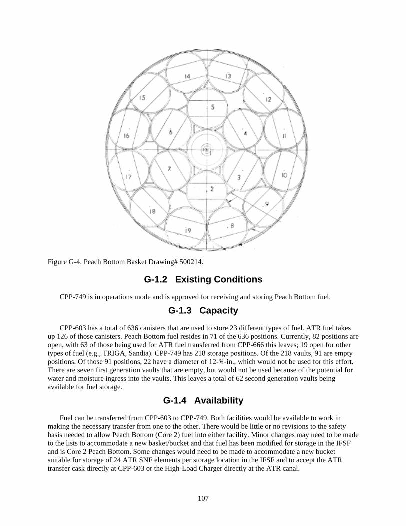
107
Figure G-4. Peach Bottom Basket Drawing# 500214.
G-1.2 Existing Conditions
CPP-749 is in operations mode and is approved for receiving and storing Peach Bottom fuel.
G-1.3 Capacity
CPP-603 has a total of 636 canisters that are used to store 23 different types of fuel. ATR fuel takes up 126 of those canisters. Peach Bottom fuel resides in 71 of the 636 positions. Currently, 82 positions are open, with 63 of those being used for ATR fuel transferred from CPP-666 this leaves; 19 open for other types of fuel (e.g., TRIGA, Sandia). CPP-749 has 218 storage positions. Of the 218 vaults, 91 are empty positions. Of those 91 positions, 22 have a diameter of 12-¾-in., which would not be used for this effort. There are seven first generation vaults that are empty, but would not be used because of the potential for water and moisture ingress into the vaults. This leaves a total of 62 second generation vaults being available for fuel storage.
G-1.4 Availability
Fuel can be transferred from CPP-603 to CPP-749. Both facilities would be available to work in making the necessary transfer from one to the other. There would be little or no revisions to the safety basis needed to allow Peach Bottom (Core 2) fuel into either facility. Minor changes may need to be made to the lists to accommodate a new basket/bucket and that fuel has been modified for storage in the IFSF and is Core 2 Peach Bottom. Some changes would need to be made to accommodate a new bucket suitable for storage of 24 ATR SNF elements per storage location in the IFSF and to accept the ATR transfer cask directly at CPP-603 or the High-Load Charger directly at the ATR canal.
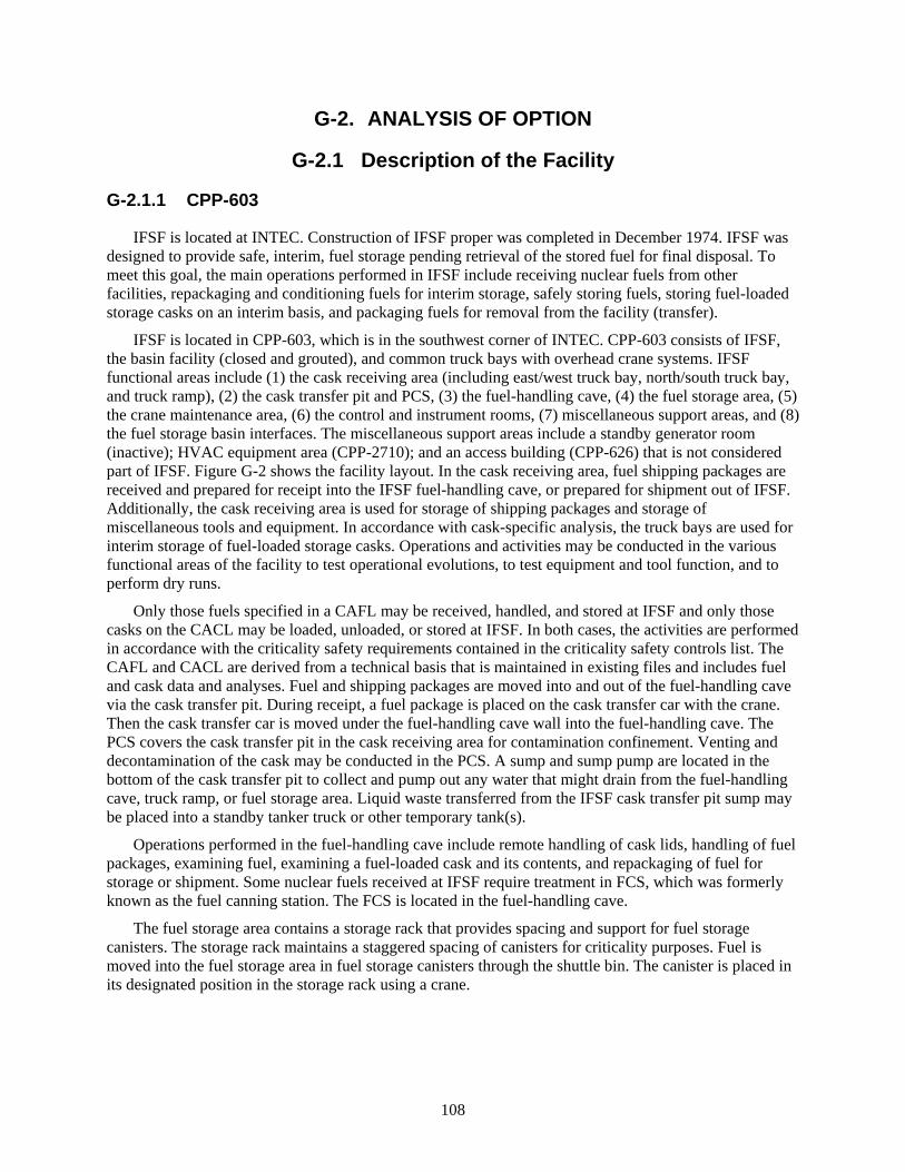
108
G-2. ANALYSIS OF OPTION
G-2.1 Description of the Facility
G-2.1.1 CPP-603
IFSF is located at INTEC. Construction of IFSF proper was completed in December 1974. IFSF was designed to provide safe, interim, fuel storage pending retrieval of the stored fuel for final disposal. To meet this goal, the main operations performed in IFSF include receiving nuclear fuels from other facilities, repackaging and conditioning fuels for interim storage, safely storing fuels, storing fuel-loaded storage casks on an interim basis, and packaging fuels for removal from the facility (transfer).
IFSF is located in CPP-603, which is in the southwest corner of INTEC. CPP-603 consists of IFSF, the basin facility (closed and grouted), and common truck bays with overhead crane systems. IFSF functional areas include (1) the cask receiving area (including east/west truck bay, north/south truck bay, and truck ramp), (2) the cask transfer pit and PCS, (3) the fuel-handling cave, (4) the fuel storage area, (5) the crane maintenance area, (6) the control and instrument rooms, (7) miscellaneous support areas, and (8) the fuel storage basin interfaces. The miscellaneous support areas include a standby generator room (inactive); HVAC equipment area (CPP-2710); and an access building (CPP-626) that is not considered part of IFSF. Figure G-2 shows the facility layout. In the cask receiving area, fuel shipping packages are received and prepared for receipt into the IFSF fuel-handling cave, or prepared for shipment out of IFSF. Additionally, the cask receiving area is used for storage of shipping packages and storage of miscellaneous tools and equipment. In accordance with cask-specific analysis, the truck bays are used for interim storage of fuel-loaded storage casks. Operations and activities may be conducted in the various functional areas of the facility to test operational evolutions, to test equipment and tool function, and to perform dry runs.
Only those fuels specified in a CAFL may be received, handled, and stored at IFSF and only those casks on the CACL may be loaded, unloaded, or stored at IFSF. In both cases, the activities are performed in accordance with the criticality safety requirements contained in the criticality safety controls list. The CAFL and CACL are derived from a technical basis that is maintained in existing files and includes fuel and cask data and analyses. Fuel and shipping packages are moved into and out of the fuel-handling cave via the cask transfer pit. During receipt, a fuel package is placed on the cask transfer car with the crane. Then the cask transfer car is moved under the fuel-handling cave wall into the fuel-handling cave. The PCS covers the cask transfer pit in the cask receiving area for contamination confinement. Venting and decontamination of the cask may be conducted in the PCS. A sump and sump pump are located in the bottom of the cask transfer pit to collect and pump out any water that might drain from the fuel-handling cave, truck ramp, or fuel storage area. Liquid waste transferred from the IFSF cask transfer pit sump may be placed into a standby tanker truck or other temporary tank(s).
Operations performed in the fuel-handling cave include remote handling of cask lids, handling of fuel packages, examining fuel, examining a fuel-loaded cask and its contents, and repackaging of fuel for storage or shipment. Some nuclear fuels received at IFSF require treatment in FCS, which was formerly known as the fuel canning station. The FCS is located in the fuel-handling cave.
The fuel storage area contains a storage rack that provides spacing and support for fuel storage canisters. The storage rack maintains a staggered spacing of canisters for criticality purposes. Fuel is moved into the fuel storage area in fuel storage canisters through the shuttle bin. The canister is placed in its designated position in the storage rack using a crane.

109
G-2.1.2 CPP-749
CPP-749, also called the Outdoor Fuel Storage Facility (OFSF), is located at the INTEC area of the INL Site. The layout of the OFSF is shown on page 2. The OFSF is designed to provide safe storage of fuel and to provide retrieval capabilities for eventual transfer of the fuel out of the facility. The facility consists of three areas, (1) the underground fuel storage portion of the facility where fuel-handling units (FHUs) are stored in underground storage vaults (designated as CPP-749).
The CPP-749 portion of this outdoor facility consists of a fenced enclosure containing vertically-oriented fuel storage vaults. The vaults are installed below grade with the tops slightly above grade. These underground fuel storage vaults provide storage and allow for eventual retrieval of the fuel. The CPP-749 facility proper is enclosed by a gated, chain-link fence, and occupies an area of approximately 260,150 ft2. A chain-link fence also separates the unirradiated Light-Water Breeder Reactor (LIGHT WATER BREEDER REACTOR) fuel storage vaults from the remainder of CPP-749 for safeguards and security purposes. Three ATR Complex (formerly known as the Reactor Technology Complex [RTC]) casks (designated 306, 701, and XMTR-11) are currently stored above ground in the southwestern portion of CPP-749.
Construction of the first-generation CPP-749 vaults (i.e., Peach Bottom and Fermi) was completed prior to the 1970-1971 timeframe. No design life was specified for these vaults. Fuel receipt began in September 1971 with storage of Peach Bottom, Unit I, Core 1, fuel storage baskets. Storage of Fermi blanket storage canisters began in January 1975. The second-generation vaults (e.g., LIGHT WATER BREEDER REACTOR, et al.) were constructed by general plant projects between 1984 and 1987. A design life of 20 years was specified for these later vaults without explicit incorporation into design parameters. Receipt and storage of 8-5/8-in.-diameter unirradiated LIGHT WATER BREEDER REACTOR fuel storage containers and LIGHT WATER BREEDER REACTOR fuel storage liners began in December 1984, and December 1985, respectively. The 8-5/8-in.-diameter unirradiated LIGHT WATER BREEDER REACTOR fuel has been disposed of and is no longer in the facility. The Shippingport PWR fuel was received in 2009. TORY-IIA fuel was received in 2010 and is currently stored in vaults with specially modified lids at the CPP-749 facility.
The CPP-749 facility contains a total of 218 underground fuel storage vaults. The vaults generally consist of 30-in.-diameter carbon steel pipes that were closed on the bottom, either by a grout plug or a welded plate, and placed in holes that were drilled in the existing soil in the area. After the vaults were installed, the area was filled with crushed rock and gravel to a height of 1.0 to 1.7 ft above natural grade level. The area was then graded with a slope for drainage. The surface in the Peach Bottom/Fermi storage vault area is gravel (west side of the CPP-749 area), but the other surfaces are paved. Several roads and gates are provided to access the facility and vaults. There are shallow drainage channels; one running north-south between the Peach Bottom/Fermi and LIGHT WATER BREEDER REACTOR vault areas, and another, also running north-south, between the PWR and Miscellaneous vault areas.
G-2.2 Barriers to Implementation
There are several barriers to implementing fuel transfers to CPP-749. Those barriers are listed below:
• The cask (Peach Bottom) that would be used in the facilities for the Peach Bottom fuel handling is not approved for fuel handling in the facilities.
• The cask (ATR transfer cask) that would be used to receive fuel directly from the ATR Canal not currently approved for fuel handling in the IFSF. This cask is similar to the High-Load Charger (which is approved), but some changes and review would be needed. Alternately, the review and changes could be implemented at ATR to allow acceptance and loading of the High-Load Charger at the ATR Canal.
110
• A new basket/bucket design would be needed to hold the size reduced Peach Bottom fuel. The basket/bucket is not on the IFSF CAFL, LST-331, or the OFSF CAFL, LST-339.
• A new basket/bucket/canister, different from the one currently designed or fabricated, that can be used to store Peach Bottom fuel in CPP-749 will be needed.
• It may be advisable to have a sealed can that is analyzed for pressure to prevent the release of gases from the element. Also, it may be advantages to evaluate a venting capability installed in the vault to prevent H2 gas, having a HEPA filter to prevent release of any radioactive particulates.
• A new fuel handling tool for the Peach Bottom fuel may need to be built.
G-2.3 Assumptions and Strategies
• Cooling requirements will need to be revised. Currently, ATR fuel decay heat cannot exceed 270 W per canister as specified by CPP-603 analysis, a constraint generally satisfied after 6 years of cooling. ATR canal capacity cannot accommodate 6 years of post-service fuel. However, preliminary analysis indicates that CPP-603 could now safely store ATR SNF canisters producing over 1000 W of heat, a constraint both satisfied by approximately 4 years out of reactor and achievable with existing ATR canal capacity.
• No additional design features need to be added to help the vaults maintain dryness such that the Peach Bottom fuel would not corrode nor produce hydrogen gas (except maybe a HEPA filter assembly on the vent line out of the vault in case hydrogen gas is generated).
• The Peach Bottom cask will be used to bottom unload at CPP-749 and top load at IFSF.
• A detailed assessment of readiness would be required for two facilities, CPP-749 and CPP-603. This includes performing full scale dry runs and proficiency operations.
• A new basket/bucket/ canister design may be needed to store Peach Bottom elements in the CPP-749 vaults. The new storage unit (basket/bucket/canister) will be able to hold 12 elements and maybe even up to 18 Peach Bottom elements.
• The new basket/bucket/canister (if used) will be designed to enable retrieval and placement of the unit into some standard canister.
• Transfers of Peach Bottom fuel to CPP-749 are likely to occur only when the weather permits.
• A new handling tool will be required to handle the canister with the 18 Peach bottom elements.
• A large overhead crane will be needed to handle cask.
• Moving the Peach Bottom elements into the 62 available CPP-749 vaults, combined with placement of ATR elements into CPP-603, means that we potentially could be successful in storing all the ATR spent fuel elements generated through the year 2050.
G-2.4 Packaging the Fuel
The 12 elements in a canister at CPP-603 will be repackaged and loaded into a stainless steel storage basket that holds 18 elements. The basket will have a spacer in the bottom to make up for the shorter length Core 2 Peach Bottom. The Peach Bottom fuel would then be transferred to CPP-749 using the Peach Bottom cask to make room for ATR in the IFSF fuel storage area. Later shipments of ATR fuel may be able to go directly from ATR to IFSF.
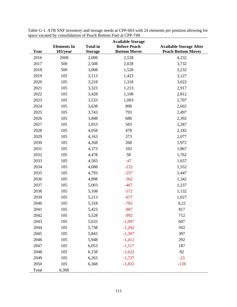
111
Table G-1. ATR SNF inventory and storage needs at CPP-603 with 24 elements per position allowing for space vacated by consolidation of Peach Bottom Fuel at CPP-749.
Year Elements In
105/year Total in Storage
Available Storage Before Peach
Bottom Moves Available Storage After
Peach Bottom Moves 2016
2008
2,008 2,528 4,232
2017
500
2,508 2,028 3,732 2018
500
3,008 1,528 3,232
2019
105
3,113 1,423 3,127 2020
105
3,218 1,318 3,022
2021
105
3,323 1,213 2,917 2022
105
3,428 1,108 2,812
2023
105
3,533 1,003 2,707 2024
105
3,638 898 2,602
2025
105
3,743 793 2,497 2026
105
3,848 688 2,392
2027
105
3,953 583 2,287 2028
105
4,058 478 2,182
2029
105
4,163 373 2,077 2030
105
4,268 268 1,972
2031
105
4,373 163 1,867 2032
105
4,478 58 1,762
2033
105
4,583 -47 1,657 2034
105
4,688 -152 1,552
2035
105
4,793 -257 1,447 2036
105
4,898 -362 1,342
2037
105
5,003 -467 1,237 2038
105
5,108 -572 1,132
2039
105
5,213 -677 1,027 2040
105
5,318 -782 9,22
2041
105
5,423 -887 817 2042
105
5,528 -992 712
2043
105
5,633 -1,097 607 2044
105
5,738 -1,202 502
2045
105
5,843 -1,307 397 2046
105
5,948 -1,412 292
2047
105
6,053 -1,517 187 2048
105
6,158 -1,622 82
2049
105
6,263 -1,727 -23 2050
105
6,368 -1,832 -128
Total
6,368

112
G-2.5 Regulatory Issues
A revision may be needed to update the environmental checklist/NEPA document to support storage of the Core #2 Peach Bottom fuel at CPP-749.
G-2.6 Cost (Capital and Operating)
Considered costs include assessments of readiness for each facility (i.e., set up, mockups, and performance), basket/bucket/canister design and analysis, basket/bucket/canister procurement, safety documentation, revisions, implementation, procedures and training, and operational costs for loading, unloading, transporting, drying, and reconfiguring. The efficient use of existing facilities avoids the need for line item capital projects.
G-2.7 Risk
Each Peach Bottom fuel element will be handled individually for repackaging. There are 12 bare Core 2 elements per canister in IFSF. The elements have been resized from approximately 144 in. to 126 in. to allow storage in the IFSF canister. When they were resized, the lifting feature on top of the elements was removed. The elements were handled using the PAR at CPP-603, which is very risky. There will be a risk in handling individual elements with a modified handling tool. Hydrogen issues have been discovered in the first generation of wells and will require some evaluation and resolution.
G-2.8 Complexity
This option is not really that different in complexity than the other options being evaluated. Fuel moves would not be much different than any other fuel move. Design of storage containers is required for just about all other options. Drying will likely be needed for most, if not all, of the options.
G-2.9 Stakeholder Value
This option utilizes existing facilities and systems to take care of the fairly long-term problem of interim storage of ATR fuel (through the year 2050 and perhaps beyond). An added possible benefit is that, if done correctly (i.e., up front), the fuel could be packaged in a configuration that prepares it for shipment directly out of the vault.
G-3. DISCRIMINATORS OF OPTION
G-3.1 Meet the Capability Gap
This option provides a potential solution to storage of ATR spent fuel though the year 2050 (and perhaps beyond). The availability of the CPP-749 and CPP-603 facilities is projected to be good for the lifetime of this evaluated period. However, other work at CPP-603 may preclude beginning the activities to support this option for 2 to 4 years.
The capacity of the CPP-749 and CPP-603 facilities, based on assumptions of this option, is projected to be good for the lifetime of this evaluated period. However, capacity becomes limited if ATR operations continue past the year 2050, because CPP-603 would be full in the year 2049 and the ATR canal would be full a year or more later depending upon actual SNF generation.
This option appears to be fully sustainable for the period evaluated. There is no real disadvantage, other than the current H2 issue at CPP-749 is not well understood.
113
G-3.1.1 Near Term
This option assumes that CPP-603 meets the needs for ATR storage in the near-term (1,000 elements transferred from CPP-666).
G-3.1.2 Midterm
The combination of using CPP-603, consolidation (16 to 24 elements per position), and this option should meet the needs for storage of ATR fuel.
G-3.1.3 Long Term
This option will meet the needs for storage of ATR fuels out to the year 2050.
G-3.2 Technical Complexity and Maturity of the Option
Technically, this option is not highly complex; however, it requires several interfaces and agreements between DOE-NE and EM that have not been in place in the past.
Packaging may be very similar or nearly the same as that currently used. The difference may be to use a stainless steel basket with a spacer (accommodate the shortened Peach Bottom Core 2 elements) instead of the current aluminum basket. Also, a canister that would fit into some standardized canister in the future may be used.
Operations compatibility/flexibility to for systems that are currently in use (or recently used) is available.
Extra fuel-handling iterations would be required to get ATR SNF ready to store at CPP-749. Also, because CPP-749 is an outdoor facility, it is dependent on weather conditions to allow working at the facility.
This option will require repackaging of the Peach Bottom fuel prior to being transferred to CPP-749.
The fact that CPP-749 is located outside makes fuel movements limited to times of good weather conditions. Fuel movements similar to this option have been performed in the past and the casks to be used have been used in the past.
The highest level of risk for this option is the actual handling of the fuel with a new tool. There is also some risk with hydrogen gas buildup, which has been found recently.
G-3.3 Meet Stakeholder, Legal, and Regulatory Requirements
Along with CPP-603, this option allows storage of all ATR elements through about the year 2050, which places all SNF into dry storage per ISA, which requires all spent fuel be out of wet storage by the year 2023. It does not meet the ISA requirement for getting all spent fuel out of the state by the year 2035.
G-3.4 Environment, Safety, and Health
A new environmental checklist/NEPA document may have to be written to allow handling and storage of Peach Bottom Core 2 fuel at CPP-749.
This option poses no adverse safety concerns because all operations are similar (or the same) as operations currently performed (or were performed in the recent past).
Peach Bottom fuel stored in CPP-749 may be less safe than being stored in CPP-603. However, Peach Bottom Core #1 fuel has been in CPP-749 for some time, only recently has hydrogen gas been discovered

114
in the wells. The reason for gas build up has not been determined, but it could be a long-term issue that must be dealt with.
G-3.5 Schedule and Funding Limitations
The timing for making this option viable is most likely to start about 2 to 4 years from now. The Fluor Idaho contract will be completing major fuel activities about this same timeframe. The schedule for performing this work may prove well to keep operations crews busy and engaged at a time when work may be winding down otherwise. Additional funding and contractual modifications will be required.
Ensure INTEC operations and safety are onboard with the concepts of this option. Obtain funding to start evaluations needed for moving the Peach Bottom fuel to CPP-749. Ensure consolidation of ATR fuels at CPP-603 is proceeding and anticipated to continue with this option. Pursue a resolution to the hydrogen gas build up in the wells.
Figure G-5. Option 7 timetable.
External Schedule Constraints
•Fun
ding
ava
ilabl
eIF
SF re
ache
s cap
acity
(16
ATR
SNF
/ por
t)
•ATR
Can
al a
t cap
acity
unle
ss S
NF sh
ips
•ISA
- al
l INL
SNF
out
of w
et st
orag
e by
en
d of
yea
r
•Ass
umed
last
ATR
SNF
gen
erat
ed(b
asis
of d
efin
ed sc
ope)
•Rep
osito
ry a
ccep
ts A
TR S
NF
2016 2017 2019 2020 2023 >> 2050 > 2055
•Res
ume
ship
ping
of A
TR S
NFto
CPP
-666
•Ren
egot
iate
Flu
or co
ntra
ct to
pro
mot
e ef
ficie
nt im
plem
enta
tion
•Dev
elop
cani
ster
des
ign
& sa
fety
case
•Mov
e Pe
achB
otto
m to
CPP
-749
•Beg
in re
pack
ing
ATR
SNF
in IF
SF(2
4 AT
R SN
F / p
ort)
•Rem
aini
ng A
TR S
NF d
ry st
ored
at I
FSF
(afte
r coo
ling
at A
TR C
anal
)
Timetable for Option X
115
G-3.6 Interfaces and Integration Requirements
Interface and integration requirements/agreements would have to be evaluated and agreed upon by Fluor, BEA, and DOE-NE and EM.
The CPP-603 fuel-handling cave would be used for both Peach Bottom packaging for transfer to CPP-749 and for receipt of ATR SNF from the ATR canal, but not at the same time. Therefore, Peach Bottom moves may be timed to coincide with an ATR core internal changeout or otherwise coordinated to avoid impact to ATR operations.
G-3.7 Safeguards and Security
No changes are needed in safeguards and security.
G-3.8 Near-Term Cost
Relative to the other options evaluated, the near-term cost of this option is low given the following:
• No line item capital project will be required.
• Initial investment includes basket/bucket/canister configuration development and analysis and development and review of fuel-handling processes.
• A NEPA compliance – environmental checklist may be needed, but the expense and impact should be minimal because actions are simply optimizing use of existing capacity within existing facilities.
G-3.9 Life-Cycle Cost
This option is low cost overall. Life-cycle cost includes both the initial costs identified as near-term cost and recurring costs accumulated over the life of the ATR SNF.
G-3.9.1 Recurring Costs
• The drying and canning requirements would be upfront costs to ensure the fuel is packaged in the appropriate configuration for dry storage.
• A purged, seal-welded, Peach Bottom fuel package will be needed for transfer to CPP-749.
• Annual facility maintenance costs for CPP-603 are considered. CPP-603 appears to offer the least expensive way to provide the fundamental functions required for placement of fuel into dry storage.
Costs are expected to be lower than most other options being considered.
G-4. RECOMMENDATION FOR OPTION
This option is the preferred option because of its simplicity, use of existing facilities, use of existing transfer/transport systems, and relatively low cost. This combination of fuel consolidations will meet the projected ATR SNF dry storage needs through the year 2050.

116
117
Appendix H
Option 8: Dry Storage at ATR Using Commercially Available Systems

118
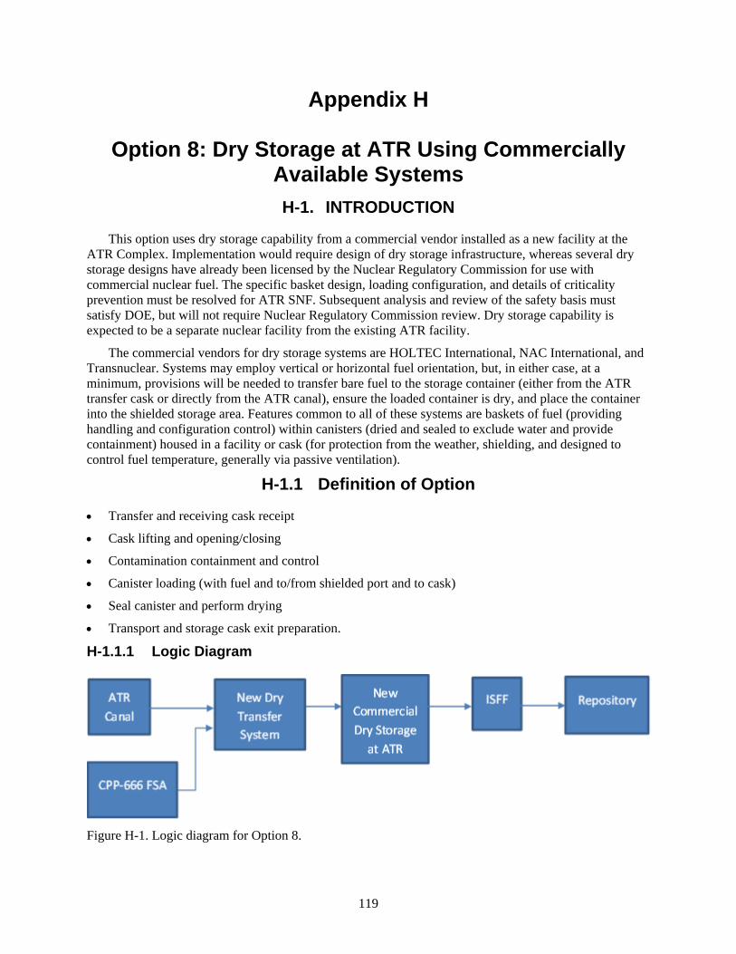
119
Appendix H
Option 8: Dry Storage at ATR Using Commercially Available Systems H-1. INTRODUCTION
This option uses dry storage capability from a commercial vendor installed as a new facility at the ATR Complex. Implementation would require design of dry storage infrastructure, whereas several dry storage designs have already been licensed by the Nuclear Regulatory Commission for use with commercial nuclear fuel. The specific basket design, loading configuration, and details of criticality prevention must be resolved for ATR SNF. Subsequent analysis and review of the safety basis must satisfy DOE, but will not require Nuclear Regulatory Commission review. Dry storage capability is expected to be a separate nuclear facility from the existing ATR facility.
The commercial vendors for dry storage systems are HOLTEC International, NAC International, and Transnuclear. Systems may employ vertical or horizontal fuel orientation, but, in either case, at a minimum, provisions will be needed to transfer bare fuel to the storage container (either from the ATR transfer cask or directly from the ATR canal), ensure the loaded container is dry, and place the container into the shielded storage area. Features common to all of these systems are baskets of fuel (providing handling and configuration control) within canisters (dried and sealed to exclude water and provide containment) housed in a facility or cask (for protection from the weather, shielding, and designed to control fuel temperature, generally via passive ventilation).
H-1.1 Definition of Option
• Transfer and receiving cask receipt
• Cask lifting and opening/closing
• Contamination containment and control
• Canister loading (with fuel and to/from shielded port and to cask)
• Seal canister and perform drying
• Transport and storage cask exit preparation.
H-1.1.1 Logic Diagram
Figure H-1. Logic diagram for Option 8.

120
H-1.1.2 Pictures
Figure H-2. Three vendors, concrete silos, bunkers, or vaults.
H-1.2 Existing Conditions
The existing ATR canal would be used to cool ATR SNF until the maximum decay heat power level is less than 30 watts (nominally less than 4 years). The ATR transfer cask could be used if an alternative transfer cask is not required. Existing open terrain inside or immediately outside the existing ATR Complex fence is available for construction of the transfer station dry storage facility.
H-1.3 Capacity
The ATR Complex is located more than 2 miles from the next nearest INL facility (i.e., INTEC). There is no limit to how large the ATR Complex dry storage facility could be constructed, but no dry storage capability currently exists at the ATR Complex. The dry storage facility would be designed for several thousand ATR SNF bundles, which would be expanded annually as additional dry storage canisters are constructed and loaded with ATR SNF. Use of poison (in baskets or other containment features) for criticality control may be beneficial to achieve economy of scale if other design parameters (such as maximum fuel temperature) are not more limiting.
H-1.4 Availability
Capital projects of this size require full compliance with DOE Order 413.3B, which will require approximately 5 to 7 years to complete planning, design, construction, readiness, and startup testing. The dry storage capacity would be able to meet ATR continuing operational needs through the year 2050 and beyond. The dry storage would not be a permanent storage repository; therefore, the dry canister would need to be emptied or transferred to a permanent repository in the future.

121
H-2. ANALYSIS OF OPTION
H-2.1 Description of the Facility
The dry storage facility would consist of a transfer cask, mobile crane, weather enclosure, drying equipment, storage pad, storage canisters, and perimeter security. The dry transfer capability could be located within the same perimeter and would include shielding and remote handling equipment to transfer bare fuel to a canister and ensure dryness. The ability to open and close casks, contain and control contamination, and confirm canister seals and monitor cover gas contents will be necessary. Visual monitoring and the ability to open canisters are desirable functions for supporting aging management practices over the projected life of the facility. Additional dry storage canisters would be fabricated and loaded each year to meet the need for additional storage as ATR continues to operate. The canister storage pad could be expanded in the future if additional storage capacity is needed.
H-2.2 BARRIERS TO IMPLEMENTATION
This option has a high initial cost. No existing infrastructure for dry storage capability exists at the ATR Complex.
H-2.3 Assumptions and Strategies
Given the stated objective of having SNF out of wet storage by December 2023, expanded wet handling and storage capability is assumed to be outside the scope of this analysis. The existing 30-ton crane capacity limits cask handling at the ATR canal and leads to the additional assumption that dry transfer will be necessary to allow transfer of ATR SNF from a relatively small cask to the new dry storage within the reactor area and to minimize constraints on concurrent reactor operations.
H-2.4 Packaging the Fuel
The existing ATR transfer cask or a newly designed transfer cask could be used for wet-to-dry transfer of ATR SNF. The stated general assumption is that ISFF will provide any additional treatment or packaging to satisfy requirements for over-the-road transport and repository acceptance. However, packaging and drying for the near-term purpose of dry storage is needed before ISFF will be available. Wet cask loading will still occur at the ATR canal for removal of ATR SNF from the reactor facility; therefore, the functions of a DTS will be required to transfer ATR SNF (element by element) from a wet-loaded cask to a suitable configuration for any of the commercial dry storage systems that may be employed. Dual purpose casks (suitable for over-the-road transport after a period of dry storage) are common for commercial fuel, but may or may not be adequate for ATR SNF, particularly after dry storage of an uncertain duration. In the context of this analysis, the proposed expansion of the ATR Canal is not being considered.
H-2.5 Regulatory Issues
A new independent safety basis would be required for the SNF dry storage facility.
H-2.6 Cost (Capital and Operating)
Although the initial capital costs are the highest for this disposition option, the annual costs are among the lowest.
122
H-2.7 Risk
Commercial dry storage facilities have been constructed and are operating successfully in support of nuclear facilities throughout the United States. Approval of a line item construction project will be needed for this option to proceed.
H-2.8 Complexity
This option will require design and construction of the complete infrastructure required for dry storage of ATR SNF. All infrastructure should be designed and constructed as a single project that would ensure compatibility of all the structures, systems, and components.
H-2.9 Stakeholder Value
This option may be particularly attractive to stakeholders because it strategically limits the wet storage of ATR fuel over the expected remaining life of the reactor.
H-3. DISCRIMINATORS OF OPTION
H-3.1 Meet the Capability Gap
This option tends to limit the capabilities for SNF handling to ATR SNF only. This works to satisfy immediate commitments, but may be short-sighted from a broader INL SNF perspective. Loss of cask handling capabilities at CPP-666 constrains SNF receiving for research purposes nationwide. New dry storage capability provides storage for ATR SNF to accommodate SNF generation after transfer to INTEC becomes unavailable (i.e., filled to capacity or removed from service). Selection of a commercial vendor with experience in the design and construction of dry storage capabilities may allow the multi-year design and construction process to be accelerated to meet ATR SNF needs beginning in 2023.
Availability is explicitly designed to satisfy projected needs to support ATR operations and does not address the potential for vulnerabilities associated with the aging of other dry storage facilities at INL (e.g., RSWF, UGFSF, and IFSF). New dry storage will be designed and built to meet the needs based on the projected ATR SNF generation rate. Modular systems and location selection will capitalize on economy of scale. The canister storage pad can be expanded in the future if additional storage capacity is needed. Additional dry storage canisters could be fabricated every year to meet the annual dry storage needs for ATR SNF.
This option requires other near-term actions to address the 2023 wet-to-dry storage objective, but it satisfies the need for dry storage of ATR SNF generated after closure of CPP-666 for the remaining operating life of the reactor.
H-3.1.1 Near Term
ATR SNF should continue to be shipped to CPP-666 FAST pools and transferred to dry storage at IFSF, while the new ATR Complex dry storage facility is being designed and constructed.
H-3.1.2 Midterm
The ATR Complex dry storage facility would meet the interim storage requirements for ATR SNF until a processing option for a permanent repository is established and ready to receive ATR SNF.

123
H-3.1.3 Long Term
Long-term dry storage of ATR SNF will require transfer to ISFF for packaging in a road-ready canister for storage in a national repository.
H-3.2 Technical Complexity and Maturity of the Option
Similar dry storage facilities exist at commercial nuclear power plants. Installation of onsite fuel transfer and storage capabilities does not require a Nuclear Regulatory Commission license: DOE approval of the safety basis is sufficient for onsite construction and operation at INL. The safety case will need to be developed and fully analyzed.
Packaging will meet the needs for safe storage and dual purpose containers may allow for transportation. However, repository acceptance is assumed to rely on ISFF to assure repackaging as needed. This option allows for a moderate packaging investment rather than attempting to meet repository requirements early.
Packaging of ATR SNF would be optimized for dry storage regardless and is not anticipated to be a discriminator. However, additional dry transfer capabilities inherent to this option could allow some additional flexibility in packaging for offsite shipment.
Dry storage at ATR would be designed and optimized for ATR SNF (only). As such, this facility is not designed to be flexible for handling, storage, and disposition needs of other INL SNF materials. This option eliminates the need to handle ATR SNF multiple times. If the dry storage system is designed and fabricated correctly, ATR SNF should be able to move directly from the ATR canal to dry storage and would not have to be relocated again until a permanent SNF repository is identified in the future. Onsite dry storage at the ATR Complex has the lowest annual transportations costs.
H-3.3 Meet Stakeholder, Legal, and Regulatory Requirements
Design and construction of a dedicated dry storage facility at the ATR Complex would satisfy the desires of ATR management to be independent of other storage facilities at INL. Continued use of the ATR canal and onsite dry storage of ATR SNF at the ATR Complex would meet the requirements of ISA only with an extremely aggressive high-risk schedule.
H-3.4 Environment, Safety, and Health
A NEPA EIS evaluation would be required prior to start of construction. ATR SNF would be protected by the same resources used to protect ATR. Passive ventilation of the dry storage system is the safety feature motivating the move from wet storage to dry storage – it allows adequate cooling from air circulation by design without the higher cost maintenance of water quality and risk associated with potential for loss of water (leading to insufficient cooling) under severe accident conditions. On the other hand, the near-term handling and dry storage of minimally cooled ATR SNF may be more hazardous than its continued wet storage.
H-3.5 Schedule and Funding Limitations
This large capital project requires congressional approval of a line item construction project and full compliance with DOE Order 413.3B, which requires approximately 5 years to complete construction and startup testing. Use of CPP-666 until 2023 or other near-term actions will be necessary to allow uninterrupted ATR operation beyond the year 2020. On this basis, successful transfer of wet stored ATR SNF to dry storage by the year 2023 will require an accelerated process, capitalizing on commercial dry storage systems to achieve completion in 4 years.

124
Figure H-3. Option 8 timetable.
H-3.6 Interfaces and Integration Requirements
ATR-INTEC interface agreements would be required for storage monitoring and reporting. Additional agreements may be required to allow return shipments of ATR SNF from INTEC to ATR dry storage. Contract and continuing support from the commercial dry storage system vendor would be required for design, construction, and the lifetime of the facility. Interactions with outside organizations are minimized by locating the dry storage facility at the ATR Complex. This eliminates the need for INTEC FAST pools to remain in operation after 2023, for NRF to agree to accept and store ATR SNF, for SRS to restart to process ATR SNF. All of which are unknown risks.
H-3.7 Safeguards and Security
Construction of a new facility must meet all safeguards and security requirements, which would require further analysis.
External Schedule Constraints
•Fun
ding
ava
ilabl
e•I
FSF
reac
hes c
apac
ity(1
6 AT
R SN
F / p
ort)
•ATR
Can
al a
t cap
acity
unle
ss S
NF sh
ips
•ISA
- al
l INL
SNF
out
of w
et st
orag
e by
en
d of
yea
r
•Ass
umed
last
ATR
SNF
gen
erat
ed(b
asis
of d
efin
ed sc
ope)
•Rep
osito
ry a
ccep
ts A
TR S
NF
2016 2017 2019 2020 2023 >> 2050 > 2055
•Res
ume
ship
ping
of A
TR S
NFto
CPP
-666
•NEP
A EI
S ta
kes 1
yea
r•S
tart
4 y
ears
for d
esig
n &
cons
truc
tion
of
cust
om d
ry st
orag
e
•New
Com
mer
cial D
ry S
tora
ge a
vaila
ble
(acc
eler
ated
sche
dule
)
•Rem
aini
ng A
TR S
NF d
ry st
ored
at A
TR
(afte
r coo
ling
at A
TR C
anal
)
Timetable for Option 7
125
H-3.8 Near-Term Cost
Relative to the other options evaluated, the near-term cost of this option is high. Considerations for near-term cost include the following:
• Development costs (loading configuration and analysis of ATR fuel for storage in a commercial off-the-shelf dry storage system)
• NEPA compliance – EIS evaluation
• Design and construction of dry transfer capability.
This option and two of the others would require a new installation with similar dry transfer functions. A rough-order-of-magnitude cost estimate for a dry transfer facility was developed specifically to support this ATR SNF options analysis.o This dry transfer capability is similar in scope and consistent in cost compared to dry transfer concepts considered in predecessor reports regarding options for the management of ATR SNF.p, q
H-3.9 Life-Cycle Cost
Overall this option is high cost. Life-cycle cost includes both the initial costs identified near-term cost and recurring costs accumulated over the life of the ATR SNF.
H-3.9.1 Recurring Costs
• Annual facility maintenance costs over the life of the facility
• Projected operating cost (for facility maintenance), material costs, and labor costs to load and transport ATR SNF
• Costs for transfer from dry storage to the repository are not included either, but are assumed to use the capability at ISFF.
While the life-cycle cost is neither the most nor the least expensive of the options considered, this option entails a line item capital project with NEPA considerations deemed likely to put both budget and schedule at risk.
H-4. RECOMMENDATION FOR OPTION
Construction of an off-the-shelf commercial dry storage facility at the ATR Complex is not a preferred option. The initial capital costs are large. While the annual operations costs are among the lowest of all options considered, the schedule risk is very high and relies on use of CPP-666 to allow ATR operation beyond the year 2020 until the commercial facility is fully functional.
o ATR SNF Management Options Study, Estimate File M000, UFC 8309, Interoffice Memorandum,
September 15, 2016. p DOE-NE, 2014, Moving ATR SNF from CPP-666 to Dry Storage Commensurate with Idaho Settlement
Agreement Milestones, DOE/ID-11517, Revision 0, September 2014. q EPRI, 1999, Cold Demonstration of a Spent Nuclear Fuel Dry Transfer System, TR-113530, Electric
Power Research Institute, Inc., September 1999.

126
127
Appendix I
Option 9: Dry Storage at ATR using a Modular Dry Canister Approach

128

129
Appendix I
Option 9: Dry Storage at ATR using a Modular Dry Canister Approach
I-1. INTRODUCTION
This option involves transfer of ATR SNF inventory, all future new discharges of ATR SNF from the ATR canal, and placement into interim dry storage canisters for safe dry storage at ATR until removal of the canisters for ultimate disposal in a U.S. repository. ATR SNF would be dried and sealed in an interim canister and stored in a dry canister storage system envisioned as canisters placed in a canister storage building. The ATR dry storage facility would also provide capability for monitoring and surveillance of the stored canisters throughout the storage period.
A new ISFF would be built at another location on the INL Site to provide conditioning and packaging capabilities to handle all INL SNF. ISFF would include an interface for receipt of SNF transfer casks from ATR and all SNF handling, drying, and canister-sealing for placement in a dry storage system (integral to ISFF). ISFF would provide the capability for opening interim canisters, retrieving fuel, and re-loading the fuel into road-ready canisters or casks as needed for transfer to the U.S. repository.
The dry storage facility would provide full capability for receiving casks from ATR, dry the fuel, and place it within a sealed canister that is subsequently stored in the facility until retrieval for ultimate disposal at a national repository.
I-1.1 Definition of Option
ATR SNF would be discharged from the ATR canal after cooling to less than 30 watts (nominally less than 4 years of cooling) and the cask would be transferred to the ATR dry storage facility (Figure I-1 shows the steps in this process):
• Transfer cask receipt
• Cask lifting and opening/closing
• Contamination containment and control
• Shielding and handling for removal of ATR SNF elements (individually)
• Shielding, loading, and handling for basket and canister designed for dry storage
• Storage transfer preparation.

130
I-1.1.1 Logic Diagram
Figure I-1. Logic diagram for Option 9.
I-1.1.2 Pictures
Figure I-2. Artist’s concept of a drying and storage facility.
I-1.2 Existing Conditions
The existing ATR canal would be used to cool the ATR SNF until the maximum decay heat power level is less than 30 watts (nominally less than 4 years). The ATR transfer cask could be used if an alternative transfer cask is not required. Existing open terrain inside or immediately outside the existing ATR Complex fence is available for construction of the dry storage facility.
I-1.3 Capacity
The ATR Complex is located more than 2 miles from the next nearest INL facility (i.e., INTEC). There is no limit on how large the ATR Complex dry storage facility could be constructed; however, no dry storage capability currently exists at the ATR Complex. The dry storage facility would be designed for several thousand ATR SNF bundles, which could be expanded to construct additional dry storage
131
canisters. ATR SNF would fill a few dry storage canisters each year depending on the number of ATR SNF bundles that can be loaded and stored in each canister.
I-1.4 Availability
Capital projects of this size require full compliance with DOE Order 413.3B, which will require at least 5 to 7 years to complete planning, design, construction, readiness, and startup testing. The dry storage capacity would be able to meet ATR continuing operational needs through the year 2050 and beyond. The dry storage would not be a permanent storage repository; therefore, fuel in the dry canister may need to be repackaged or transferred to a road-ready canister before shipment to a permanent repository.
I-2. ANALYSIS OF OPTION
I-2.1 Description of the Facility
The dry storage facility would consist of a transfer cask, crane(s), drying equipment, storage canisters, canister storage building, and perimeter security. The dry transfer capability would be integral to the facility and would include the shielding and remote handling equipment to transfer bare fuel to a canister and ensure dryness. The ability to open and close casks, contain and control contamination, and confirm canister seals and monitor cover gas contents will be necessary. Visual monitoring and the ability to open canisters are desirable functions to support aging management practices over the projected life of the facility. Additional dry storage canisters would be fabricated and loaded each year to meet the need for additional storage as ATR continues to operate. The canister storage building could be expanded in the future if additional storage capacity is needed.
I-2.2 Barriers to Implementation
This option has high initial cost. There is no existing infrastructure for dry storage capability at the ATR Complex.
I-2.3 Assumptions and Strategies
An estimated 5 to 7 years is needed to accommodate the DOE Order 413.3B process. The ATR SNF is assumed to be in good condition with no known cladding breach at the time of transfer to dry storage.
I-2.4 Packaging the Fuel
The existing ATR transfer cask or a newly designed transfer cask could be used for wet-to-dry transfer of ATR SNF. The existing ATR canal facilities could be used. ATR SNF should be packaged in dry storage canisters, which will allow the SNF to be retrieved or shipped directly to a permanent repository.
I-2.5 Regulatory Issues
A new independent safety basis would be required for the SNF dry storage facility.
I-2.6 Cost (Capital and Operating)
Preliminary costs include design and construction of a transfer cask, mobile crane, weather enclosure, drying equipment, storage facility, storage canisters, and perimeter security. Annual costs will include facility maintenance costs, procurement of storage canisters to safely store ATR SNF, and labor costs to
132
load and transport each storage canister. Although initial capital costs are among the highest for this disposition option, annual costs are among the lowest.
I-2.7 Risk
Custom dry storage facilities have been constructed and are operating successfully in the United States; IFSF is one example. Approval of a line item construction project will need to be needed for this option to proceed.
I-2.8 Complexity
This option will require design and construction of the complete infrastructure required for dry storage of ATR SNF. All infrastructure should be designed and constructed as a single project that would ensure compatibility of all the structures, systems, and components.
I-2.9 Stakeholder Value
Because of the schedule and funding constraints associated with a line item construction project and the DOE Order 413.3B process, this option will require other near-term actions to satisfy the 2023 ISA date for all SNF to be out of wet storage. This dry storage would employ a configuration not intended to be “road ready” for transport to a national repository. As such, this option is probably neutral in stakeholder value with respect to SNF leaving Idaho.
I-3. DISCRIMINATORS OF OPTION
I-3.1 Meet the Capability Gap
New dry storage will be designed and built to meet the needs based on the projected ATR SNF generation rate. Storage systems and location selection will capitalize on economy of scale. This option requires other near-term actions to address the 2023 wet-to-dry storage objective; however, it satisfies the need for dry storage of ATR SNF generated after the closure of CPP-666 for the remaining operating life of the reactor. Additional dry storage canisters could be fabricated every year to meet the annual dry storage needs for ATR SNF. Availability is explicitly designed to satisfy projected needs to support ATR operations and does not address potential for vulnerabilities associated with the aging of other dry storage facilities at INL (e.g., RSWF, UGFSF, and IFSF).
This option tends to limit capabilities for SNF handling to ATR SNF only. This works to satisfy immediate commitments, but may be short-sighted from a broader INL SNF perspective. Loss of cask-handling capabilities at CPP-666 constrains SNF receiving for research purposes nationwide.
I-3.1.1 Near Term
ATR SNF should continue to be shipped to CPP-666 FAST pools and transferred to dry storage at IFSF while the new ATR Complex dry storage facility is being designed and constructed.
I-3.1.2 Midterm
The ATR Complex dry storage facility would meet the interim storage requirements for ATR SNF until a permanent repository is established and ready to receive ATR SNF.
I-3.1.3 Long Term
Long-term dry storage of ATR SNF will require transfer to ISFF for packaging in a road-ready canister for storage in a national repository.

133
I-3.2 Technical Complexity and Maturity of the Option
Design and construction of a new dry storage facility is a risk for this option.
This option eliminates the need to handle ATR SNF multiple times. If the dry storage system is designed and fabricated correctly, ATR SNF should be able to move directly from the ATR canal to dry storage and would not have to be relocated again until a permanent SNF repository is identified in the future. Onsite dry storage at the ATR Complex has the lowest annual transportations costs. This option also invests less in packaging, which produces less waste should processing become preferable at a later date.
This option is designed and optimized for ATR SNF (only); it is not designed to be flexible for handling, storage, and disposition needs of other INL SNF materials.
Packaging of ATR SNF would be optimized for dry storage regardless and is not anticipated to be a discriminator. Nominal cost estimates for all dry storage options were compared based on packages with 48 ATR SNF elements per canister. The additional dry transfer handling capabilities inherent to this option could allow some additional flexibility in packaging for offsite shipment. Packaging will meet the needs for safe storage. However, repository acceptance is assumed to rely on ISFF to assure repackaging as needed.
I-3.3 Meet Stakeholder, Legal, and Regulatory Requirements
Design and construction of a dedicated dry storage facility at the ATR Complex would be desired by ATR management to be independent of other storage facilities at INL. Continued use of the ATR canal and onsite dry storage of ATR SNF at the ATR Complex would meet the requirements of ISA.
I-3.4 Environment, Safety, and Health
NEPA evaluation would be required prior to start of construction. ATR SNF would be protected by the same resources used to protect ATR. Passive ventilation of the dry storage system is the safety feature motivating the move from wet storage to dry storage – it allows adequate cooling from air circulation by design without the higher cost maintenance of water quality and risk associated with potential for loss of water (leading to insufficient cooling) under severe accident conditions. However, arguably, the near-term handling and dry storage of minimally cooled ATR SNF could be more hazardous than its continued wet storage.
I-3.5 Schedule and Funding Limitations
This large capital project requires congressional approval of a line item construction project and full compliance with DOE Order 413.3B, which will require at least 5 years to complete construction and startup testing. There is significant schedule risk associated with having this facility designed, built, and operational in the year 2024; more ATR SNF would be generated with uninterrupted ATR operation than there is space in dry storage to accommodate it without deferment of the 2023 wet-to-dry commitment or other action to increase near-term dry storage capacity.
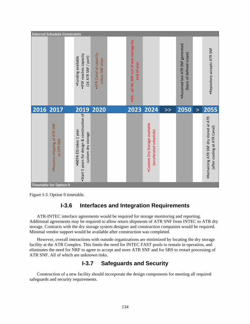
134
Figure I-3. Option 9 timetable.
I-3.6 Interfaces and Integration Requirements
ATR-INTEC interface agreements would be required for storage monitoring and reporting. Additional agreements may be required to allow return shipments of ATR SNF from INTEC to ATR dry storage. Contracts with the dry storage system designer and construction companies would be required. Minimal vendor support would be available after construction was completed.
However, overall interactions with outside organizations are minimized by locating the dry storage facility at the ATR Complex. This limits the need for INTEC FAST pools to remain in operation, and eliminates the need for NRF to agree to accept and store ATR SNF and for SRS to restart processing of ATR SNF. All of which are unknown risks.
I-3.7 Safeguards and Security
Construction of a new facility should incorporate the design components for meeting all required safeguards and security requirements.
External Schedule Constraints
•Fun
ding
ava
ilabl
e•I
FSF
reac
hes c
apac
ity(1
6 AT
R SN
F / p
ort)
•ATR
Can
al a
t cap
acity
unle
ss S
NF sh
ips
•ISA
- al
l INL
SNF
out
of w
et st
orag
e by
en
d of
yea
r
•Ass
umed
last
ATR
SNF
gen
erat
ed(b
asis
of d
efin
ed sc
ope)
•Rep
osito
ry a
ccep
ts A
TR S
NF
2016 2017 2019 2020 2023 2024 >> 2050 > 2055
•Res
ume
ship
ping
of A
TR S
NFto
CPP
-666
•NEP
A EI
S ta
kes 1
yea
r•S
tart
5 y
ears
for d
esig
n &
cons
truc
tion
of
cust
om d
ry st
orag
e
•Cus
tom
Dry
Sto
rage
ava
ilabl
e (a
ccel
erat
ed sc
hedu
le)
•Rem
aini
ng A
TR S
NF d
ry st
ored
at A
TR
(afte
r coo
ling
at A
TR C
anal
)
Timetable for Option 9
135
I-3.8 Near-Term Cost
Relative to the other options evaluated, the near-term cost of this option is high. Considerations for near-term cost include the following:
• Development costs (loading configuration and analysis for ATR fuel in storage and design of drying and transfer systems)
• NEPA compliance – EIS evaluation.
This option and two of the others would require a new installation with similar dry transfer functions. A rough-order-of-magnitude cost estimate for a dry transfer facility was developed specifically to support this ATR SNF options analysis.r This dry transfer capability is similar in scope and consistent in cost compared to dry transfer concepts considered in predecessor reports regarding options for the management of ATR SNF.s, t
I-3.9 Life-Cycle Cost
Overall this option is high cost. Life-cycle cost includes both the initial costs identified as near-term cost and recurring costs accumulated over the life of the ATR SNF.
I-3.9.1 Recurring Costs
• Annual facility maintenance costs over the life of the facility
• Projected operating cost for material costs and for labor costs to load and transport ATR SNF
• Costs for transfer from dry storage to a repository are not included either, but are assumed to use the capability at ISFF.
Dry storage at the ATR Complex has the highest initial costs to create an entirely new infrastructure for storage of ATR SNF, but with the least transportation needed, recurring costs are some of the lowest. A line item construction project with NEPA considerations and without the benefit of an existing Nuclear Regulatory Commission-licensed (i.e., off-the-shelf) design to garner stakeholder acceptance, this option is likely to put both schedule and budget at risk.
I-4. RECOMMENDATION FOR OPTION
This option is not a preferred option. The additional expense associated with the custom design of dry storage does not appear to offer commensurate benefit when compared to adaptation of commercial systems addressed in Option 8. The schedule and budget risks are very high and rely on use of CPP-666 to allow ATR operation beyond the year 2020 until the dry storage facility is fully functional.
r “ATR SNF Management Options Study,” Estimate File M000, UFC 8309, Interoffice Memorandum,
September 15, 2016. s DOE-NE, 2014, Moving ATR SNF from CPP-666 to Dry Storage Commensurate with Idaho Settlement
Agreement Milestones, DOE/ID-11517, Revision 0, September 2014. t EPRI, 1999, Cold Demonstration of a Spent Nuclear Fuel Dry Transfer System, TR-113530, Electric
Power Research Institute, Inc. (EPRI). September 1999.

136
137
Appendix J
Option 10: Processing of ATR SNF at the FSA FDP Cell using the ZIRCEX Process

138
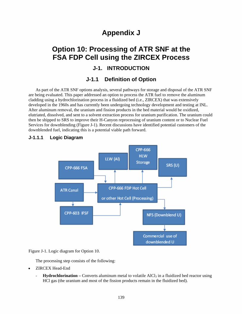
139
Appendix J
Option 10: Processing of ATR SNF at the FSA FDP Cell using the ZIRCEX Process
J-1. INTRODUCTION
J-1.1 Definition of Option
As part of the ATR SNF options analysis, several pathways for storage and disposal of the ATR SNF are being evaluated. This paper addressed an option to process the ATR fuel to remove the aluminum cladding using a hydrochlorination process in a fluidized bed (i.e., ZIRCEX) that was extensively developed in the 1960s and has currently been undergoing technology development and testing at INL. After aluminum removal, the uranium and fission products in the bed material would be oxidized, elutriated, dissolved, and sent to a solvent extraction process for uranium purification. The uranium could then be shipped to SRS to improve their H-Canyon reprocessing of uranium content or to Nuclear Fuel Services for downblending (Figure J-1). Recent discussions have identified potential customers of the downblended fuel, indicating this is a potential viable path forward.
J-1.1.1 Logic Diagram
Figure J-1. Logic diagram for Option 10.
The processing step consists of the following:
• ZIRCEX Head-End
- Hydrochlorination – Converts aluminum metal to volatile AlCl3 in a fluidized bed reactor using HCl gas (the uranium and most of the fission products remain in the fluidized bed).

140
- Pyrohydrolysis – Converts the AlCl3 to aluminum oxide for disposal as low-level waste.
- Oxidation – After the aluminum is volatilized and removed, converts the solid UCl3 to U3O8 (as well as oxidizing any fission product chlorides).
• Elutriation – U3O8 fine particles are much lighter than alumina bed particles, allowing it to be dissolution and solvent extraction. (The following steps would only need to be conducted once every 1 to 3 years in a campaign that would last a few weeks.)
- Dissolution – dissolves the collected U3O8/fission products in nitric acid
- Solvent extraction – separates the uranium from the fission products
- HLW vitrification – converts fission products to storage form.
The ZIRCEX head-end of the process, which is the portion of this process still being developed, is depicted in Figure J-2.
J-1.1.2 Pictures
Figure J-2. Depiction of fluidized beds for the hydrochlorination, pyrohydrolysis, and elutriation steps.
J-1.2 Existing Conditions
Uranium dissolution, the standard PUREX solvent extraction process using centrifugal contactors, and the HLW vitrification processes are well-developed and commercially used. There is an ongoing INL (DOE-NE-funded) project to develop the head-end ZIRCEX process for use with Zircaloy-clad fuels. The original ZIRCEX process development was conducted at Oak Ridge National Laboratory’s Gaseous Diffusion Plant,i, ii Oak Ridge National Laboratory,iii Brookhaven National Laboratoryiv, v and Argonne National Laboratoryvi, vii primarily for U-Zr alloy fuel, but also for U-Al alloy fuels and was well documented in progress reports. Development resulted in a conceptual plant design for applying the

141
process to commercial light water reactor fuels.ii The initial step of the original process consisted of reacting the cladding material with gaseous HCl at 300°C (for Al fuels) to 400°C (for Zr fuels) to separate the cladding from the fuel as chloride vapor. Because the hydrochlorination process is highly exothermic, the reaction is carried out in a fluidized bed to extract the heat. As part of this testing, a non-irradiated fuel pilot-scale unit (less than 20-kg fuel charges), which included a 6-in. diameter hydrochlorination unit followed by a pyrohydrolyzer that converted ZrCl4 or AlCl3 to the oxide, was operated with both highly enriched U-Zircaloy and U-Al fuels (Figure J-3). In addition, a laboratory-scale hydrochlorinator unit (about 100 to 200-g fuel charges) was demonstrated with irradiated U-Zircaloy and U-Al alloy fuels. In both cases, after cladding removal, fluorination was generally used to volatilize the uranium to remove it from the fluidized bed material; however, some testing that used elutriation of uranium from the bed was successful.viii, ix
Figure J-3. 1960s era ZIRCEX pilot plant was successfully run at Argonne National Laboratory.
INL currently has a development program for evaluating the ZIRCEX process for zirconium-clad fuels without utilizing fluorination. Laboratory-scale testing (i.e., 5 to 50-g samples) was completed at INL with Zircaloy (i.e., non-radioactive) to determine optimal operating parameters for chlorination of Zircaloy-clad fuels (e.g., temperatures, concentrations, and flow rates). In addition, irradiated fuel testing was completed (i.e., 15 to 50-g samples) to determine relative reaction rates of irradiated and unirradiated fuel rates, fission product carryover to the ZrCl4 product, and determination if oxide coating inhibits reaction rate on irradiated fuels. These tests showed that reaction rates of irradiated and unirradiated fuels were similar, indicating that an unirradiated pilot plant could potentially sufficiently predict overall reaction rates for irradiated fuels. In addition, it was determined that good filtration is important and can be achieved to minimize fission product contamination of the ZrCl4 waste. Tests showed that the cladding product does not contain significant fission products (i.e., a Class B or C low-level waste can be achieved). These tests also showed that the oxide coating on the fuel had sufficient cracks/holes to allow initiation of the chlorination reaction without additional treatment to remove the oxide coating. Figure J-4 shows the apparatus used. Hot cell testing was done at the Remote Analytical Laboratory (CPP-684) hot cell and the system has recently been dismantled.

142
Figure J-4. Equipment used for laboratory-scale testing of Zr-clad fuels.
A pilot plant for non-irradiated fuel with a 6-in. diameter fluidized bed hydrochlorinator and pyrohydrolyzer is being fabricated to enable investigation into optimizing reaction rates while maintaining the required heat of reaction removal, pyrohydrolysis of the resulting ZrCl4, and the ability to oxidize uranium and elutriate it out of the bed. This pilot facility is approximately 80% fabricated. The current pilot plant design developed at INL is depicted in Figure J-5.
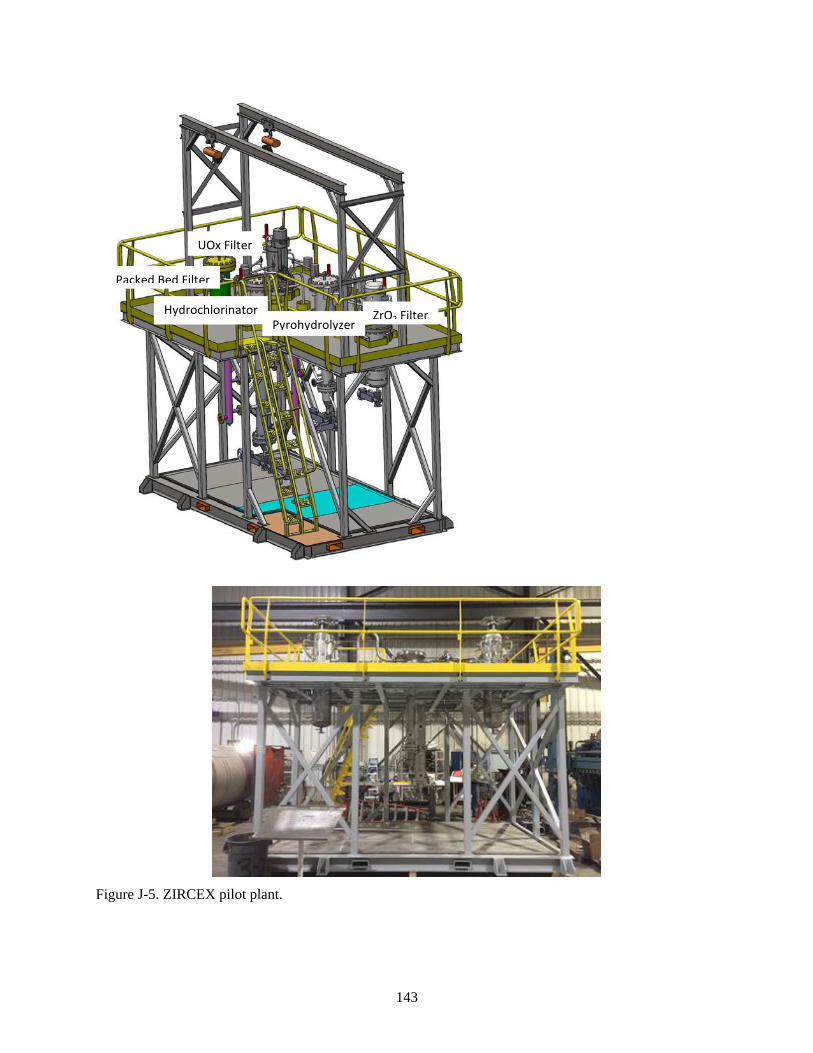
143
Figure J-5. ZIRCEX pilot plant.
Hydrochlorinator
Packed Bed Filter
UOx Filter
Pyrohydrolyzer ZrO2 Filter
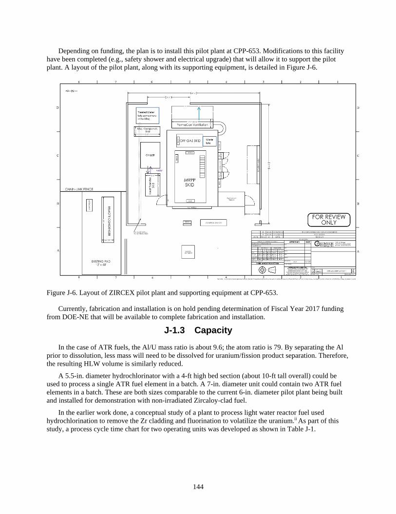
144
Depending on funding, the plan is to install this pilot plant at CPP-653. Modifications to this facility have been completed (e.g., safety shower and electrical upgrade) that will allow it to support the pilot plant. A layout of the pilot plant, along with its supporting equipment, is detailed in Figure J-6.
Figure J-6. Layout of ZIRCEX pilot plant and supporting equipment at CPP-653.
Currently, fabrication and installation is on hold pending determination of Fiscal Year 2017 funding from DOE-NE that will be available to complete fabrication and installation.
J-1.3 Capacity
In the case of ATR fuels, the Al/U mass ratio is about 9.6; the atom ratio is 79. By separating the Al prior to dissolution, less mass will need to be dissolved for uranium/fission product separation. Therefore, the resulting HLW volume is similarly reduced.
A 5.5-in. diameter hydrochlorinator with a 4-ft high bed section (about 10-ft tall overall) could be used to process a single ATR fuel element in a batch. A 7-in. diameter unit could contain two ATR fuel elements in a batch. These are both sizes comparable to the current 6-in. diameter pilot plant being built and installed for demonstration with non-irradiated Zircaloy-clad fuel.
In the earlier work done, a conceptual study of a plant to process light water reactor fuel used hydrochlorination to remove the Zr cladding and fluorination to volatilize the uranium.ii As part of this study, a process cycle time chart for two operating units was developed as shown in Table J-1.
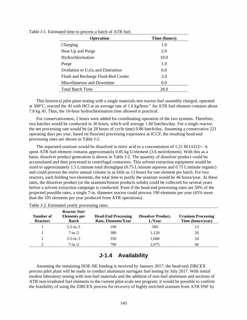
145
Table J-1. Estimated time to process a batch of ATR fuel. Operation Time (hours)
Charging 1.0 Heat Up and Purge 2.0 Hydrochlorination 10.0 Purge 1.0 Oxidation to U3O8 and Elutriation 6.0 Flush and Recharge Fluid-Bed Cooler 2.0 Miscellaneous and Downtime 6.0 Total Batch Time 28.0
This historical pilot plant testing with a single materials test reactor fuel assembly charged, operated
at 300°C, reacted the Al with HCl at an average rate of 1.6 kg/hour.x An ATR fuel element contains about 7.8 kg Al. Thus, the 10-hour hydrochlorination time allowed is practical.
For conservativeness, 2 hours were added for coordinating operation of the two systems. Therefore, two batches would be conducted in 30 hours, which will average 1.60 batches/day. For a single reactor, the net processing rate would be (at 28 hours of cycle time) 0.86 batch/day. Assuming a conservative 221 operating days per year, based on fluorinel processing experience at ICCP, the resulting head-end processing rates are shown in Table J-2.
The separated uranium would be dissolved in nitric acid to a concentration of 1.21 M UO22+. A spent ATR fuel element contains approximately 0.85 kg U/element (3.6 mol/element). With this as a basis, dissolver product generation is shown in Table J-2. The quantity of dissolver product could be accumulated and then processed in centrifugal contactors. This solvent extraction equipment would be sized to approximately 1.5 L/minute total throughput (0.75 L/minute aqueous and 0.75 L/minute organic) and could process the entire annual volume in as little as 13 hours for one element per batch. For two reactors, each holding two elements, the total time to purify the uranium would be 46 hours/year. At these rates, the dissolver product (or the uranium/fission products solids) could be collected for several years before a solvent extraction campaign is conducted. Even if the head-end processing rates are 50% of the projected possible rates, a single 7-in. diameter reactor could process 190 elements per year (45% more than the 105 elements per year produced from ATR operations).
Table J-2. Estimated yearly processing rates.
Number of Reactors
Reactor Size/ Elements per
Batch Head-End Processing Rate, Elements/Year
Dissolver Product, L/Year
Uranium Processing Time (hours/year)
1 5.5-in./1 190 560 13 1 7-in./2 380 1,120 26 2 5.5-in./1 350 1,040 24 2 7-in./2 700 2,075 46
J-1.4 Availability
Assuming the remaining DOE-NE funding is received by January 2017, the head-end ZIRCEX process pilot plant will be ready to conduct aluminum surrogate fuel testing by July 2017. With initial modest laboratory testing with non-fuel materials and the addition of non-fuel aluminum and sections of ATR non-irradiated fuel elements to the current pilot-scale test program, it would be possible to confirm the feasibility of using the ZIRCEX process for recovery of highly enriched uranium from ATR SNF by
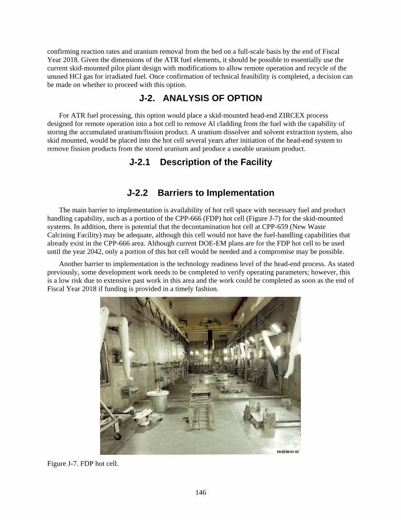
146
confirming reaction rates and uranium removal from the bed on a full-scale basis by the end of Fiscal Year 2018. Given the dimensions of the ATR fuel elements, it should be possible to essentially use the current skid-mounted pilot plant design with modifications to allow remote operation and recycle of the unused HCl gas for irradiated fuel. Once confirmation of technical feasibility is completed, a decision can be made on whether to proceed with this option.
J-2. ANALYSIS OF OPTION
For ATR fuel processing, this option would place a skid-mounted head-end ZIRCEX process designed for remote operation into a hot cell to remove Al cladding from the fuel with the capability of storing the accumulated uranium/fission product. A uranium dissolver and solvent extraction system, also skid mounted, would be placed into the hot cell several years after initiation of the head-end system to remove fission products from the stored uranium and produce a useable uranium product.
J-2.1 Description of the Facility
J-2.2 Barriers to Implementation
The main barrier to implementation is availability of hot cell space with necessary fuel and product handling capability, such as a portion of the CPP-666 (FDP) hot cell (Figure J-7) for the skid-mounted systems. In addition, there is potential that the decontamination hot cell at CPP-659 (New Waste Calcining Facility) may be adequate, although this cell would not have the fuel-handling capabilities that already exist in the CPP-666 area. Although current DOE-EM plans are for the FDP hot cell to be used until the year 2042, only a portion of this hot cell would be needed and a compromise may be possible.
Another barrier to implementation is the technology readiness level of the head-end process. As stated previously, some development work needs to be completed to verify operating parameters; however, this is a low risk due to extensive past work in this area and the work could be completed as soon as the end of Fiscal Year 2018 if funding is provided in a timely fashion.
Figure J-7. FDP hot cell.
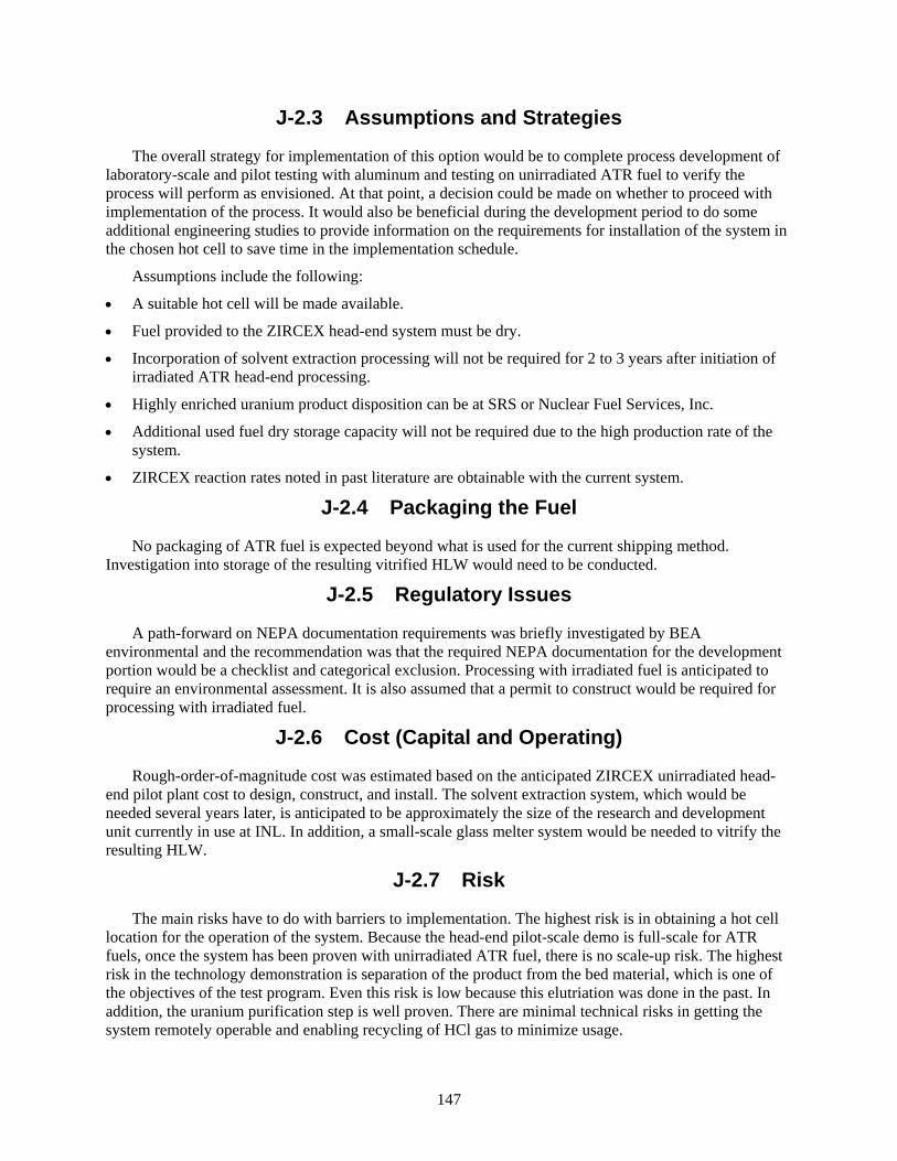
147
J-2.3 Assumptions and Strategies
The overall strategy for implementation of this option would be to complete process development of laboratory-scale and pilot testing with aluminum and testing on unirradiated ATR fuel to verify the process will perform as envisioned. At that point, a decision could be made on whether to proceed with implementation of the process. It would also be beneficial during the development period to do some additional engineering studies to provide information on the requirements for installation of the system in the chosen hot cell to save time in the implementation schedule.
Assumptions include the following:
• A suitable hot cell will be made available.
• Fuel provided to the ZIRCEX head-end system must be dry.
• Incorporation of solvent extraction processing will not be required for 2 to 3 years after initiation of irradiated ATR head-end processing.
• Highly enriched uranium product disposition can be at SRS or Nuclear Fuel Services, Inc.
• Additional used fuel dry storage capacity will not be required due to the high production rate of the system.
• ZIRCEX reaction rates noted in past literature are obtainable with the current system.
J-2.4 Packaging the Fuel
No packaging of ATR fuel is expected beyond what is used for the current shipping method. Investigation into storage of the resulting vitrified HLW would need to be conducted.
J-2.5 Regulatory Issues
A path-forward on NEPA documentation requirements was briefly investigated by BEA environmental and the recommendation was that the required NEPA documentation for the development portion would be a checklist and categorical exclusion. Processing with irradiated fuel is anticipated to require an environmental assessment. It is also assumed that a permit to construct would be required for processing with irradiated fuel.
J-2.6 Cost (Capital and Operating)
Rough-order-of-magnitude cost was estimated based on the anticipated ZIRCEX unirradiated head-end pilot plant cost to design, construct, and install. The solvent extraction system, which would be needed several years later, is anticipated to be approximately the size of the research and development unit currently in use at INL. In addition, a small-scale glass melter system would be needed to vitrify the resulting HLW.
J-2.7 Risk
The main risks have to do with barriers to implementation. The highest risk is in obtaining a hot cell location for the operation of the system. Because the head-end pilot-scale demo is full-scale for ATR fuels, once the system has been proven with unirradiated ATR fuel, there is no scale-up risk. The highest risk in the technology demonstration is separation of the product from the bed material, which is one of the objectives of the test program. Even this risk is low because this elutriation was done in the past. In addition, the uranium purification step is well proven. There are minimal technical risks in getting the system remotely operable and enabling recycling of HCl gas to minimize usage.
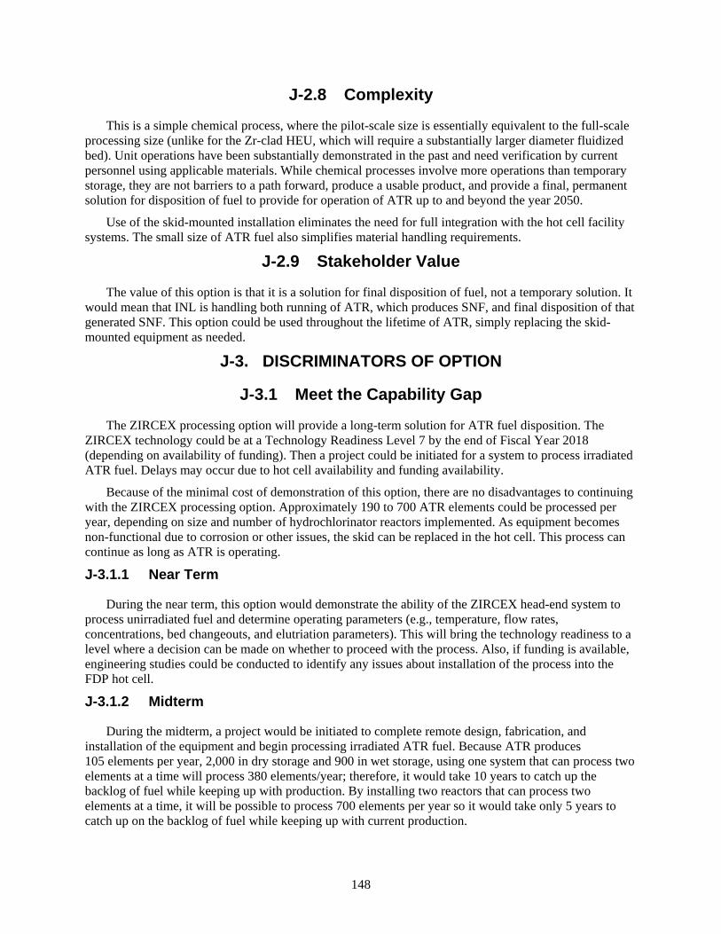
148
J-2.8 Complexity
This is a simple chemical process, where the pilot-scale size is essentially equivalent to the full-scale processing size (unlike for the Zr-clad HEU, which will require a substantially larger diameter fluidized bed). Unit operations have been substantially demonstrated in the past and need verification by current personnel using applicable materials. While chemical processes involve more operations than temporary storage, they are not barriers to a path forward, produce a usable product, and provide a final, permanent solution for disposition of fuel to provide for operation of ATR up to and beyond the year 2050.
Use of the skid-mounted installation eliminates the need for full integration with the hot cell facility systems. The small size of ATR fuel also simplifies material handling requirements.
J-2.9 Stakeholder Value
The value of this option is that it is a solution for final disposition of fuel, not a temporary solution. It would mean that INL is handling both running of ATR, which produces SNF, and final disposition of that generated SNF. This option could be used throughout the lifetime of ATR, simply replacing the skid-mounted equipment as needed.
J-3. DISCRIMINATORS OF OPTION
J-3.1 Meet the Capability Gap
The ZIRCEX processing option will provide a long-term solution for ATR fuel disposition. The ZIRCEX technology could be at a Technology Readiness Level 7 by the end of Fiscal Year 2018 (depending on availability of funding). Then a project could be initiated for a system to process irradiated ATR fuel. Delays may occur due to hot cell availability and funding availability.
Because of the minimal cost of demonstration of this option, there are no disadvantages to continuing with the ZIRCEX processing option. Approximately 190 to 700 ATR elements could be processed per year, depending on size and number of hydrochlorinator reactors implemented. As equipment becomes non-functional due to corrosion or other issues, the skid can be replaced in the hot cell. This process can continue as long as ATR is operating.
J-3.1.1 Near Term
During the near term, this option would demonstrate the ability of the ZIRCEX head-end system to process unirradiated fuel and determine operating parameters (e.g., temperature, flow rates, concentrations, bed changeouts, and elutriation parameters). This will bring the technology readiness to a level where a decision can be made on whether to proceed with the process. Also, if funding is available, engineering studies could be conducted to identify any issues about installation of the process into the FDP hot cell.
J-3.1.2 Midterm
During the midterm, a project would be initiated to complete remote design, fabrication, and installation of the equipment and begin processing irradiated ATR fuel. Because ATR produces 105 elements per year, 2,000 in dry storage and 900 in wet storage, using one system that can process two elements at a time will process 380 elements/year; therefore, it would take 10 years to catch up the backlog of fuel while keeping up with production. By installing two reactors that can process two elements at a time, it will be possible to process 700 elements per year so it would take only 5 years to catch up on the backlog of fuel while keeping up with current production.

149
J-3.1.3 Long Term
The long-term outlook would be to continue processing ATR fuel throughout the lifetime of ATR, replacing the skid-mounted equipment as necessary. To maintain 105 elements per year, one reactor processing only one element per batch would be more than sufficient, but by using the slightly larger reaction vessel, charging two elements per batch would decrease operating costs somewhat by only processing about 2.5 months per year plus turnaround times. Uranium separation operations would only have to be done in a short campaign every third or fourth year.
J-3.2 Technical Complexity and Maturity of the Option
Although there was extensive testing of the ZIRCEX process in the 1960s in addition to the testing completed at INL, the head-end aluminum processing system would require some laboratory verification to bring it to a Technology Readiness Level 4 and pilot plant testing to bring it to a Technology Readiness Level 7 (Figure J-8). The dissolution and solvent extraction portion of the process and the HLW vitrification equipment is already considered to be at Technology Readiness Level 8 and 9, although some formulation development may be needed for this particular waste stream.
Figure J-8. Technology readiness level timeline.
Operation of ATR processing equipment is fully compatible with larger-scale naval fuel ZIRCEX equipment operation. Operations with the same crew in the same hot cell will be complementary and very cost effective. Because of the adjacent water storage and transfer system, the ability to source candidate spent fuels from multiple storage locations is virtually unlimited. The processing rate is flexible to accommodate various operating strategies.
Because the fuel going into the ZIRCEX process has to be dry, it cannot receive fuel directly from the CPP-666 basin. Similar to a canning option, the fuel will have to undergo a drying operation. Based on design of the fuel, air drying may be an option by simply having a temporary storage time in the cell to allow the fuel time to dry.
The largest risk to the success of this option is obtaining a suitable location for operation of the irradiated fuel system.
Assuming successful demonstration of the process with unirradiated ATR fuel, there is no scale-up risk. The uranium purification step is well proven. There are minimal technical risks in getting the system remotely operable and enabling recycling of HCl gas to minimize usage.
Use of this process is much more efficient and provides great advantages over shipment of nuclear materials cross country. Shipping recycled uranium is much more flexible and much less costly.
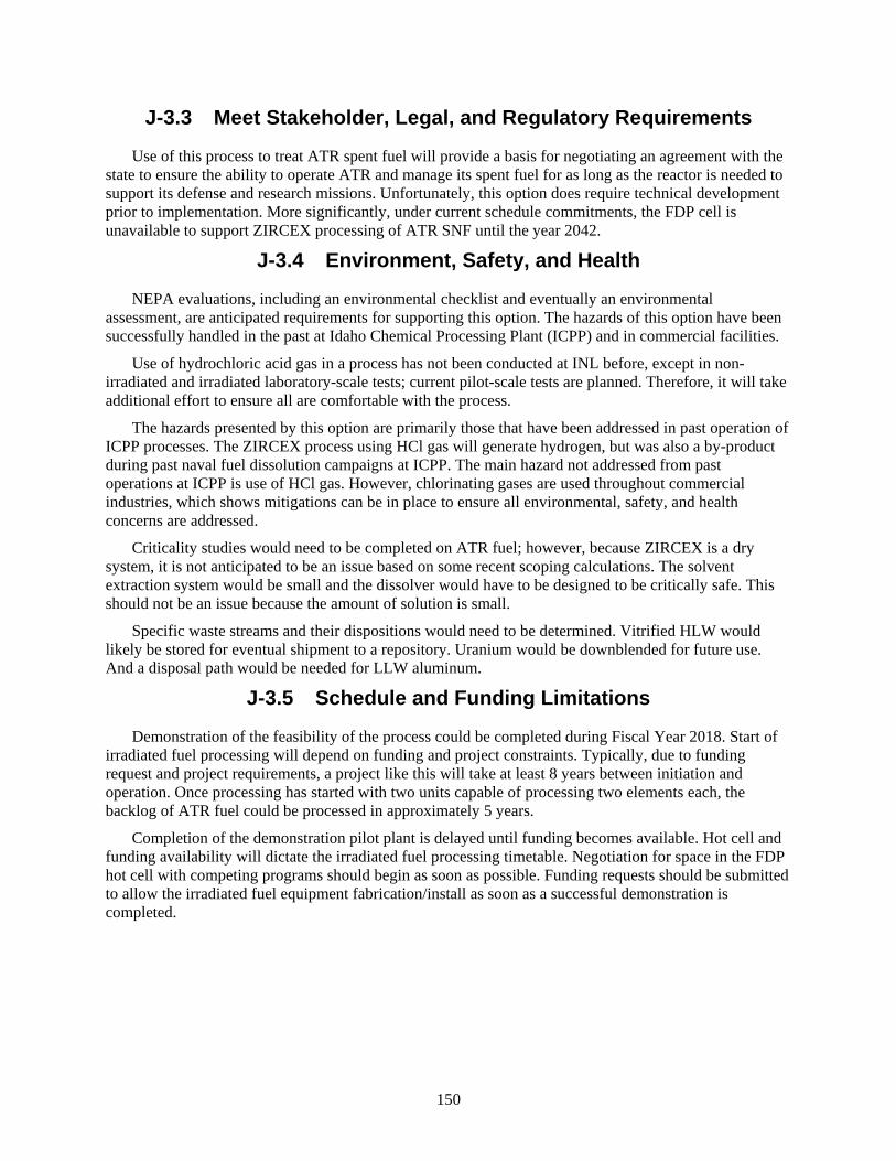
150
J-3.3 Meet Stakeholder, Legal, and Regulatory Requirements
Use of this process to treat ATR spent fuel will provide a basis for negotiating an agreement with the state to ensure the ability to operate ATR and manage its spent fuel for as long as the reactor is needed to support its defense and research missions. Unfortunately, this option does require technical development prior to implementation. More significantly, under current schedule commitments, the FDP cell is unavailable to support ZIRCEX processing of ATR SNF until the year 2042.
J-3.4 Environment, Safety, and Health
NEPA evaluations, including an environmental checklist and eventually an environmental assessment, are anticipated requirements for supporting this option. The hazards of this option have been successfully handled in the past at Idaho Chemical Processing Plant (ICPP) and in commercial facilities.
Use of hydrochloric acid gas in a process has not been conducted at INL before, except in non-irradiated and irradiated laboratory-scale tests; current pilot-scale tests are planned. Therefore, it will take additional effort to ensure all are comfortable with the process.
The hazards presented by this option are primarily those that have been addressed in past operation of ICPP processes. The ZIRCEX process using HCl gas will generate hydrogen, but was also a by-product during past naval fuel dissolution campaigns at ICPP. The main hazard not addressed from past operations at ICPP is use of HCl gas. However, chlorinating gases are used throughout commercial industries, which shows mitigations can be in place to ensure all environmental, safety, and health concerns are addressed.
Criticality studies would need to be completed on ATR fuel; however, because ZIRCEX is a dry system, it is not anticipated to be an issue based on some recent scoping calculations. The solvent extraction system would be small and the dissolver would have to be designed to be critically safe. This should not be an issue because the amount of solution is small.
Specific waste streams and their dispositions would need to be determined. Vitrified HLW would likely be stored for eventual shipment to a repository. Uranium would be downblended for future use. And a disposal path would be needed for LLW aluminum.
J-3.5 Schedule and Funding Limitations
Demonstration of the feasibility of the process could be completed during Fiscal Year 2018. Start of irradiated fuel processing will depend on funding and project constraints. Typically, due to funding request and project requirements, a project like this will take at least 8 years between initiation and operation. Once processing has started with two units capable of processing two elements each, the backlog of ATR fuel could be processed in approximately 5 years.
Completion of the demonstration pilot plant is delayed until funding becomes available. Hot cell and funding availability will dictate the irradiated fuel processing timetable. Negotiation for space in the FDP hot cell with competing programs should begin as soon as possible. Funding requests should be submitted to allow the irradiated fuel equipment fabrication/install as soon as a successful demonstration is completed.

151
Figure J-9. Option 10 timetable.
J-3.6 Interfaces and Integration Requirements
To complete this option, some of the major interfaces/integration requirements include the following:
• Integration of ATR feasibility tests with DOE-NE testing on Zr fuels in the pilot plant.
• Integration/interfaces with the use of a portion of FDP hot cell for irradiated fuel processing.
J-3.7 Safeguards and Security
Because there will be a large quantity of Category 1 material recovered and stored in a single location (the U3O8 awaiting processing), Category 1 security requirements will have to be met. Therefore, the location of the process will be limited to a facility that could be upgraded to meet the level of security protection necessary to protect a Category 1 quantity of material.
J-3.8 Near-Term Cost
Initial testing should be completed on a laboratory scale to scope out the reaction rates using aluminum prior to going to the pilot scale. In addition, completion of scoping tests with Al and simulants in the pilot plant currently being fabricated (completion of installation is DOE-NE funding dependent) would be needed. NEPA compliance would also contribute to the near-term cost.
External Schedule Constraints
•IFS
F re
ache
s cap
acity
(16
ATR
SNF
/ por
t)
•ATR
Can
al a
t cap
acity
unle
ss S
NF sh
ips
•ISA
- al
l INL
SNF
out
of w
et st
orag
e by
en
d of
yea
r
•Ass
umed
last
ATR
SNF
gen
erat
ed(b
asis
of d
efin
ed sc
ope)
•Rep
osito
ry a
ccep
ts A
TR S
NF
2016 2017 2018 2019 2020 > 2023 >> 2042 > 2050 > 2055
•Res
ume
ship
ping
of A
TR S
NFto
CPP
-666
•Pilo
t tes
ting
with
surr
ogat
e fu
el
•Con
firm
ZIR
CEX
feas
ibili
ty fo
r ATR
SNF
•FDP
cell
beco
mes
ava
ilabl
e fo
r ZIR
CEX
•Rem
aini
ng A
TR S
NF d
ry st
ored
at A
TR
(afte
r coo
ling
at A
TR C
anal
)
Timetable for Option 10
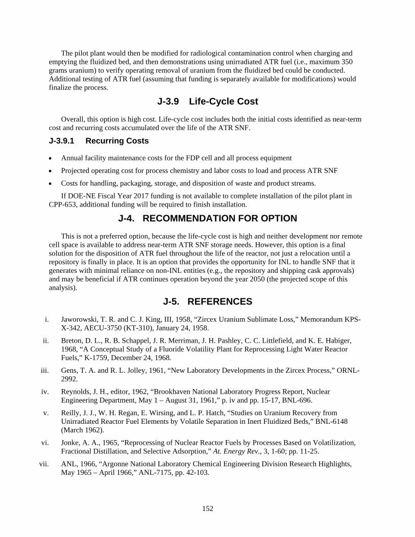
152
The pilot plant would then be modified for radiological contamination control when charging and emptying the fluidized bed, and then demonstrations using unirradiated ATR fuel (i.e., maximum 350 grams uranium) to verify operating removal of uranium from the fluidized bed could be conducted. Additional testing of ATR fuel (assuming that funding is separately available for modifications) would finalize the process.
J-3.9 Life-Cycle Cost
Overall, this option is high cost. Life-cycle cost includes both the initial costs identified as near-term cost and recurring costs accumulated over the life of the ATR SNF.
J-3.9.1 Recurring Costs
• Annual facility maintenance costs for the FDP cell and all process equipment
• Projected operating cost for process chemistry and labor costs to load and process ATR SNF
• Costs for handling, packaging, storage, and disposition of waste and product streams.
If DOE-NE Fiscal Year 2017 funding is not available to complete installation of the pilot plant in CPP-653, additional funding will be required to finish installation.
J-4. RECOMMENDATION FOR OPTION
This is not a preferred option, because the life-cycle cost is high and neither development nor remote cell space is available to address near-term ATR SNF storage needs. However, this option is a final solution for the disposition of ATR fuel throughout the life of the reactor, not just a relocation until a repository is finally in place. It is an option that provides the opportunity for INL to handle SNF that it generates with minimal reliance on non-INL entities (e.g., the repository and shipping cask approvals) and may be beneficial if ATR continues operation beyond the year 2050 (the projected scope of this analysis).
J-5. REFERENCES
i. Jaworowski, T. R. and C. J. King, III, 1958, “Zircex Uranium Sublimate Loss,” Memorandum KPS-X-342, AECU-3750 (KT-310), January 24, 1958.
ii. Breton, D. L., R. B. Schappel, J. R. Merriman, J. H. Pashley, C. C. Littlefield, and K. E. Habiger, 1968, “A Conceptual Study of a Fluoride Volatility Plant for Reprocessing Light Water Reactor Fuels,” K-1759, December 24, 1968.
iii. Gens, T. A. and R. L. Jolley, 1961, “New Laboratory Developments in the Zircex Process,” ORNL-2992.
iv. Reynolds, J. H., editor, 1962, “Brookhaven National Laboratory Progress Report, Nuclear Engineering Department, May 1 – August 31, 1961,” p. iv and pp. 15-17, BNL-696.
v. Reilly, J. J., W. H. Regan, E. Wirsing, and L. P. Hatch, “Studies on Uranium Recovery from Unirradiated Reactor Fuel Elements by Volatile Separation in Inert Fluidized Beds,” BNL-6148 (March 1962).
vi. Jonke, A. A., 1965, “Reprocessing of Nuclear Reactor Fuels by Processes Based on Volatilization, Fractional Distillation, and Selective Adsorption,” At. Energy Rev., 3, 1-60; pp. 11-25.
vii. ANL, 1966, “Argonne National Laboratory Chemical Engineering Division Research Highlights, May 1965 – April 1966,” ANL-7175, pp. 42-103.
153
viii. Monk, T. H., J. H. Pashley, and R.B. Schappel, 1970, “Semiworks Fluid-Bed Studies of Volatility Process for Zircaloy-Clad Uranium Dioxide Power Reactor Fuels,” Chemical Engineering Progress Symposium Series, No. 105, Vol. 66, pp. 180-190.
ix. Gens, T. A. and R. L. Jolley, 1961, “New Laboratory Developments in the Zircex Process,” ORNL-2992.
x. ANL, 1964, “Argonne National Laboratory Chemical Engineering Division Research Highlights, May 1963-April 1964,” ANL-6875, p. 84.

154
155
Appendix K
Option 11: Extended Wet Storage of ATR SNF at FSA

156
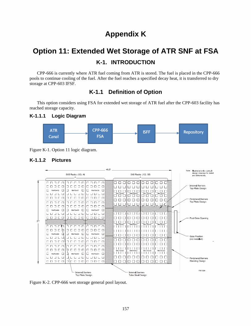
157
Appendix K
Option 11: Extended Wet Storage of ATR SNF at FSA K-1. INTRODUCTION
CPP-666 is currently where ATR fuel coming from ATR is stored. The fuel is placed in the CPP-666 pools to continue cooling of the fuel. After the fuel reaches a specified decay heat, it is transferred to dry storage at CPP-603 IFSF.
K-1.1 Definition of Option
This option considers using FSA for extended wet storage of ATR fuel after the CPP-603 facility has reached storage capacity.
K-1.1.1 Logic Diagram
Figure K-1. Option 11 logic diagram.
K-1.1.2 Pictures
Figure K-2. CPP-666 wet storage general pool layout.
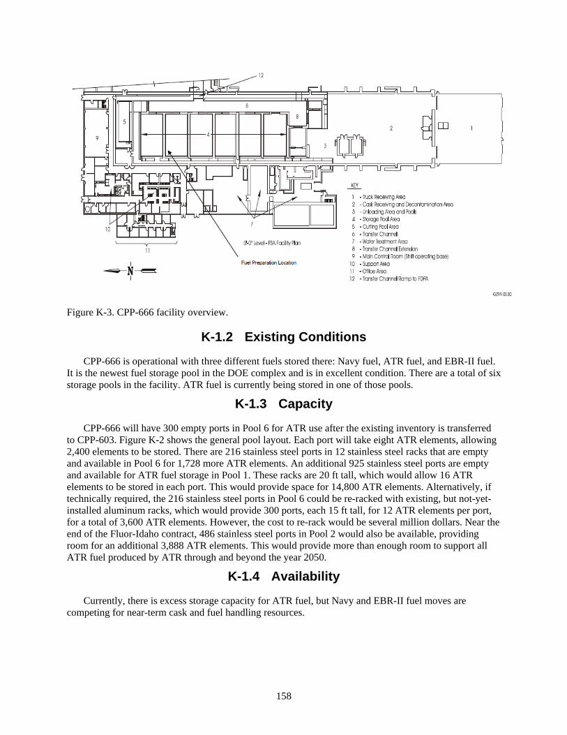
158
Figure K-3. CPP-666 facility overview.
K-1.2 Existing Conditions
CPP-666 is operational with three different fuels stored there: Navy fuel, ATR fuel, and EBR-II fuel. It is the newest fuel storage pool in the DOE complex and is in excellent condition. There are a total of six storage pools in the facility. ATR fuel is currently being stored in one of those pools.
K-1.3 Capacity
CPP-666 will have 300 empty ports in Pool 6 for ATR use after the existing inventory is transferred to CPP-603. Figure K-2 shows the general pool layout. Each port will take eight ATR elements, allowing 2,400 elements to be stored. There are 216 stainless steel ports in 12 stainless steel racks that are empty and available in Pool 6 for 1,728 more ATR elements. An additional 925 stainless steel ports are empty and available for ATR fuel storage in Pool 1. These racks are 20 ft tall, which would allow 16 ATR elements to be stored in each port. This would provide space for 14,800 ATR elements. Alternatively, if technically required, the 216 stainless steel ports in Pool 6 could be re-racked with existing, but not-yet-installed aluminum racks, which would provide 300 ports, each 15 ft tall, for 12 ATR elements per port, for a total of 3,600 ATR elements. However, the cost to re-rack would be several million dollars. Near the end of the Fluor-Idaho contract, 486 stainless steel ports in Pool 2 would also be available, providing room for an additional 3,888 ATR elements. This would provide more than enough room to support all ATR fuel produced by ATR through and beyond the year 2050.
K-1.4 Availability
Currently, there is excess storage capacity for ATR fuel, but Navy and EBR-II fuel moves are competing for near-term cask and fuel handling resources.
159
K-2. ANALYSIS OF OPTION
K-2.1 Description of the Facility
The FSA, with its supporting systems and facilities, occupies approximately 79,100 ft2 of the CPP-666 building. The FSA contains the following primary and support areas (Figure K-3): (1) truck receiving area; (2) cask receiving and decontamination area; (3) unloading area (including unloading and isolation pools); (4) storage pool area; (5) cutting pool area; (6) transfer channel; (7) water treatment area; (8) transfer channel extension; (9) main control room (now used as the shift operating base); (10) support areas, such as HVAC; (11) office areas and other miscellaneous support areas, consisting of storage rooms, rest rooms, change rooms, and showers; and (12) transfer channel ramp to the Flourinel Dissolution Process Area. The underwater area consists of the unloading and isolation pools, the storage pools, the cutting pool, the transfer channel, and the transfer channel extension. Structural features or systems interface with or are shared by the Flourinel Dissolution Process Area, including the transfer channel ramp.
K-2.2 Barriers to Implementation
The barriers to continuing operations at CPP-666 are the cost (maintenance and operations) and whether the state will allow it to continue to store fuel after the year 2023.
K-2.3 Assumptions and Strategies
• DOE negotiates with the state of Idaho to allow continued use of CPP-666 to support operation of ATR at least through the year 2050 and to store its fuel in CPP-666 until a new ISFF is built and processes the spent ATR elements in it to send to a repository.
• Assumes the ATR fuel will use CPP-666 for cooling then transfer to CPP-603 until that facility is at storage capacity.
• An updated security plan will be needed to allow extension of fuel storage at CPP-666 beyond April 2024.
K-2.4 Packaging the Fuel
The ATR fuel will be placed into buckets of current design used to store the fuel at CPP-666. No additional packaging would be expected to be needed until the fuel is removed from the pools and packaged at ISFF for disposition.
K-2.5 Regulatory Issues
The state has an agreement to have all spent fuel out of wet storage by the end of 2023. This option would require negotiations by DOE and approval from the state.
K-2.6 Cost (Capital and Operating)
There are enough existing buckets for all 300 existing ports or for 2,400 elements. The duration for unloading the ATR elements is only one shift per shipment. It is anticipated that only 15 shipments of ATR elements would be required to handle a whole year’s discharge from the reactor. If other operations are on-going during this time, the costs can be shared for maintaining the facility and for keeping the crew(s) busy. If not, then ATR would need to pay for full support of the facility and the operations and support people. If all of the projected 3,570 ATR SNF elements generated from 2016 through 2050 are to be stored concurrently at FSA, an additional 147 buckets would be needed, but then the oldest fuel would

160
be at extreme risk of cladding penetration over decades of wet storage before the youngest fuel would be received from the ATR canal.
K-2.7 Risk
The greatest risk to this option is being able to negotiate an agreement with the state of Idaho to allow continued storage of spent fuel at CPP-666. The second greatest risk is the corrosion rate of the ATR fuel cladding. Aluminum clad fuel is NOT acceptable for long-term underwater storage. Even with ultra-pure water, the cladding will eventually pit and uranium and fission products will migrate into the water from the fuel.
K-2.8 Complexity
Operation of the facility is not complex because it has been running since it was built in the 1980s. Shipping and storage of the fuel is also not very complex.
K-2.9 Stakeholder Value
This option is cost effective for a near-term stopgap solution, but does not address midterm and long-term issues associated with wet storage. It also does nothing to prepare the fuel to leave the state. There is high risk of extremely expensive recovery over the long term should corrosion produce leaking fuel.
K-3. DISCRIMINATORS OF OPTION
K-3.1 Meet the Capability Gap
The availability of the CPP-666 facility is projected to be good until it reaches the design life (i.e., April 2024). If it is to remain open, then a life-extension evaluation would be required. Additionally, continued storage in the CPP-666 pools will require negotiation with the state of Idaho. The capacity of the CPP-666 facility is projected to be more than sufficient for ATR SNF generated through the year 2050. Also, the long-term underwater storage of aluminum fuel will result in pitting corrosion.
K-3.1.1 Near Term
This option meets the capability gap for the near term.
K-3.1.2 Midterm
For 10 to 20 years maximum, this option meets the capability gap, assuming the state of Idaho will negotiate continued storage in the CPP-666 pools.
K-3.1.3 Long Term
Because of the high possibility of corrosion occurring with aluminum fuel, this option would not likely meet the capability gap for the long term.
K-3.2 Technical Complexity and Maturity of the Option
The option of having CPP-666 remain open is a very mature option because the facility has been in operational mode since the 1980s. However, it must be noted that the facility has a 40-year design life and it is currently 32 years old.
161
All systems are currently in use and are available to operations. Packaging is expected to be the same as what is currently used.
K-3.3 Meet Stakeholder, Legal, and Regulatory Requirements
The facility currently meets the stakeholder, legal, and regulatory requirements. The milestone for 2023, per ISA, is to have all fuel out of wet storage. This requirement would require negotiation and explanation about why it should remain open. It would require an evaluation to determine if the facility continues to meet the requirements.
K-3.4 Environment, Safety, and Health
A NEPA evaluation would be needed, but impact should be minimal for continuation of the intended use of an existing facility, at least in the near term.
The facility reaches its design life in 2024. There are some issues with the pool liner, which means an evaluation needs to be performed.
The disadvantage is the fact that corrosion of the aluminum fuel after long-term underwater storage is inevitable. Pitting corrosion, which is prevalent, is likely to release uranium and fission products into the water.
K-3.5 Schedule and Funding Limitations
Fluor-Idaho has three main schedule issues at FAST: Navy (including the “pieces, parts, and fines”), ATR to IFSF, and EBR-II to MFC/RSWF. The Navy effort is actually the smallest of the three. This would also include working with the funding limitations between DOE-NE and DOE-EM.
The timing for making this option viable is most likely to start in about 3 to 4 years from now, when the current inventory of ATR fuel is moved to IFSF and is continuing on a yearly basis with about 15 shipments per year.
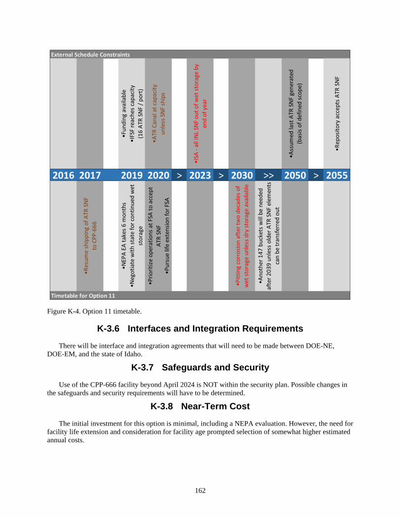
162
Figure K-4. Option 11 timetable.
K-3.6 Interfaces and Integration Requirements
There will be interface and integration agreements that will need to be made between DOE-NE, DOE-EM, and the state of Idaho.
K-3.7 Safeguards and Security
Use of the CPP-666 facility beyond April 2024 is NOT within the security plan. Possible changes in the safeguards and security requirements will have to be determined.
K-3.8 Near-Term Cost
The initial investment for this option is minimal, including a NEPA evaluation. However, the need for facility life extension and consideration for facility age prompted selection of somewhat higher estimated annual costs.
External Schedule Constraints
•Fun
ding
ava
ilabl
e•I
FSF
reac
hes c
apac
ity(1
6 AT
R SN
F / p
ort)
•ATR
Can
al a
t cap
acity
unle
ss S
NF sh
ips
•ISA
- al
l INL
SNF
out
of w
et st
orag
e by
en
d of
yea
r
•Ass
umed
last
ATR
SNF
gen
erat
ed(b
asis
of d
efin
ed sc
ope)
•Rep
osito
ry a
ccep
ts A
TR S
NF
2016 2017 2019 2020 > 2023 > 2030 >> 2050 > 2055
•Res
ume
ship
ping
of A
TR S
NFto
CPP
-666
•NEP
A EA
take
s 6 m
onth
s•N
egot
iate
with
stat
e fo
r con
tinue
d w
et
stor
age
•Prio
ritize
ope
ratio
ns a
t FSA
to a
ccep
t AT
R SN
F•P
ursu
e lif
e ex
tens
ion
for F
SA
•Pitt
ing
corr
osio
n af
ter t
wo
deca
des o
f w
et st
orag
e un
less
dry
stor
age
avai
labl
e
•Ano
ther
147
buc
kets
will
be
need
ed
afte
r 203
9 un
less
old
er A
TR S
NF e
lem
ents
ca
n be
tran
sfer
red
out
Timetable for Option 11
163
K-3.9 Life-Cycle Cost
Overall this option is mid-range in cost, with a high and increasing risk of recovery expenses as corrosion progresses during the proposed storage period. Life-cycle cost includes both the initial costs identified as near-term cost and recurring costs accumulated over the life of the ATR SNF.
K-3.9.1 Recurring Costs
• The duration for unloading the ATR elements is only one shift per shipment. Nominally, 15 shipments of ATR elements would handle a whole year’s discharge from the reactor. CPP-666’s facility maintenance and fuel-handling operations were considered.
• There are enough existing buckets for 2,400 ATR elements in all 300 existing ports. If additional ports are used, additional buckets would be needed.
• Costs for transfer from wet storage to a repository are not included, but are assumed to use the capability at ISFF.
The use of CPP-666 beyond April 2024 will also require evaluation for facility life extension. These costs were not defined or bounded in this rough estimate and physical upgrades for security contribute significant financial risk to this option
K-4. RECOMMENDATION FOR OPTION
This option is not a preferred option because corrosion is expected to be problematic with wet storage over the long term. Because of its simplicity, use of an existing facility, use of existing transfer/transport systems, and cost, this option could be beneficial. However, in the short term, availability is limited by competing obligations and midterm use would require negotiation with the state. In addition, long-term underwater storage of aluminum fuel has safety concerns due to corrosion. Because of the corrosion concerns, it would not be recommended to use CPP-666 as a stand-alone option for long-term, out-to-2050, aluminum fuel storage.

164
165
Appendix L
Option 12: Conversion of the FSA Wet Storage Pool to Dry Storage

166
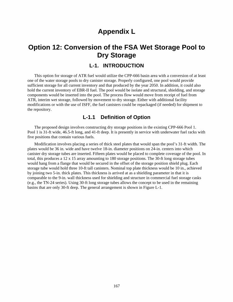
167
Appendix L
Option 12: Conversion of the FSA Wet Storage Pool to Dry Storage
L-1. INTRODUCTION
This option for storage of ATR fuel would utilize the CPP-666 basin area with a conversion of at least one of the water storage pools to dry canister storage. Properly configured, one pool would provide sufficient storage for all current inventory and that produced by the year 2050. In addition, it could also hold the current inventory of EBR-II fuel. The pool would be isolate and structural, shielding, and storage components would be inserted into the pool. The process flow would move from receipt of fuel from ATR, interim wet storage, followed by movement to dry storage. Either with additional facility modifications or with the use of ISFF, the fuel canisters could be repackaged (if needed) for shipment to the repository.
L-1.1 Definition of Option
The proposed design involves constructing dry storage positions in the existing CPP-666 Pool 1. Pool 1 is 31-ft wide, 46.5-ft long, and 41-ft deep. It is presently in service with underwater fuel racks with five positions that contain various fuels.
Modification involves placing a series of thick steel plates that would span the pool’s 31-ft width. The plates would be 36 in. wide and have twelve 18-in. diameter positions on 24-in. centers into which canister dry storage tubes are inserted. Fifteen plates would be placed to complete coverage of the pool. In total, this produces a 12 x 15 array amounting to 180 storage positions. The 30-ft long storage tubes would hang from a flange that would be secured in the offset of the storage position shield plug. Each storage tube would hold three 10-ft tall canisters. Nominal top plate thickness would be 10 in., achieved by joining two 5-in. thick plates. This thickness is arrived at as a shielding parameter in that it is comparable to the 9-in. wall thickness used for shielding and structure in commercial fuel storage casks (e.g., the TN-24 series). Using 30-ft long storage tubes allows the concept to be used in the remaining basins that are only 30-ft deep. The general arrangement is shown in Figure L-1.

168
Figure L-1. Pool layout.
Weighing approximately 20 tons each, the plates can be delivered by legal weight trucks. Crane CRN-FS-903 would be used to unload them from the trucks for tube assembly and placement in the pool.
Installation of the plates could be done while the pool is flooded, by floating them into position using the buoyancy of the canister storage tubes guided by the CRN-FS-901. This would be necessary due to the 10-ton load limit of CRN-FS-901 and the limited operation area of the 130-ton CRN-FS-903. Because of space limitations, to make the turn from the transfer channel into the Pool 1 area, only the center two tubes would be in place during initial plate placement to allow them to fit through the slot in the wall between the transfer channel and the pool. Plate edges would have a step configuration to interlock to prevent radiation shine.
Fuel would be moved from wet storage positions to Isolation Pool #2 and placed in eight position baskets like those currently in use in canisters at CPP-603. The canister design would have a diameter of 16 in. and 10-ft long. The design height of 10 ft limits the canister to only two eight-position baskets (i.e., a total 16 ATR elements). The top end of the canister would contain a steel shield plug. The canister and lid connections are illustrated in Figure L-2.

169
Figure L-2. General canister cutaway and lid plug-purge/vent connections.
The baskets would be loaded underwater into the canister that has been staged in the isolation pool. The canister lid would be put into place and secured and the purge and vacuum lines would be attached to the quick connectors mounted in the lid. The canister would be purged of water by pressurization with nitrogen and dried by vacuum and alternating heated nitrogen purges if needed.
Once drying has been completed, either the CRN-FS-903 or 901 crane will lift the loaded canister into the transfer cask, which is located at the working floor level and mounted in an air pallet structure. The pallet structure is staged on a steel plate that has the same elevation as the top of the dry storage pool steel cover plates. The air pallet and transfer cask are manually positioned over the desired storage location and the CRN-901 hook attached to the canister. The bottom plate of the transfer cask would be slid out from below the canister, allowing the canister to be lowered into the storage tube. Three canisters would be placed in each tube, allowing for a nominal loading of 48 ATR elements per storage position. Operationally, the shield plug in the top of the canister limits personnel exposure when placing the additional canisters. For all 180 tubes filled to capacity using these baskets, the capacity would be 8,640
This image cannot currently be displayed.
This image cannot currently be displayed.
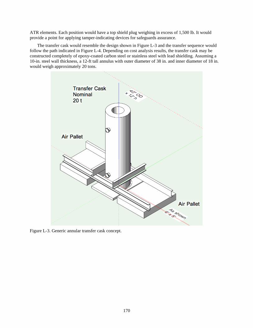
170
ATR elements. Each position would have a top shield plug weighing in excess of 1,500 lb. It would provide a point for applying tamper-indicating devices for safeguards assurance.
The transfer cask would resemble the design shown in Figure L-3 and the transfer sequence would follow the path indicated in Figure L-4. Depending on cost analysis results, the transfer cask may be constructed completely of epoxy-coated carbon steel or stainless steel with lead shielding. Assuming a 10-in. steel wall thickness, a 12-ft tall annulus with outer diameter of 38 in. and inner diameter of 18 in. would weigh approximately 20 tons.
Figure L-3. Generic annular transfer cask concept.
171
Figure L-4. Nominal transfer sequence.
Following an expected, extended dry storage period, the canisters could be seal welded at the lid seam and the vent and purge penetrations, then certified for shipping by doing a radiological gas sip test for shipping. Alternately, the baskets could be repackaged into another canister according to the requirements of the final repository. This could be done in ISFF, or in the CPP-666 unloading pool, or, with modifications, in the CPP-666 FDP cell.
This image cannot currently be displayed.

172
L-1.1.1 Logic Diagram
Figure L-5. Option 11 logic diagram.
L-1.1.2 Pictures
L-1.2 Existing Conditions
L-1.3 Capacity
L-1.4 Availability
L-2. ANALYSIS OF OPTION
L-2.1 Description of the Facility
The CPP-666 facility includes FSA (sometimes called FAST), which is the newest wet storage pool system in the DOE complex, having entered service in 1984. As shown in Figures L-6 and L-7, it is composed of six primary storage pools, two unloading and isolation pools, and a cutting pool, which are connected by a transfer channel. Wet operations are connected to the dry operations of the FDP hot cell by a pair of transfer carts that raise fuel baskets from the transfer channel into the grade level inside the dry hot cell. A 130-ton crane that can handle commercial-scale spent fuel storage and shipping casks serves the truck receiving bay and unloading pool. The storage pools are served by a pair of 10-ton cranes that span the pool with an operator walkway to allow direct line of sight positioning of tools and components submerged in the pools. The facility was built to the current seismic code and has undergone periodic review for Performance Category 3 Natural Hazard Phenomena analysis. It has full high-

173
efficiency particulate air-ventilated exhaust from all radiological areas of the building. The pools are stainless steel-lined and have a sump monitor system to allow detection of leaks to the concrete structure. The facility has a current safety analysis report and security basis for storage of highly enriched fuels. However, the existing security plan does not address the use of this facility for fuel storage after April 2024.
Figure L-6. Facility layout.
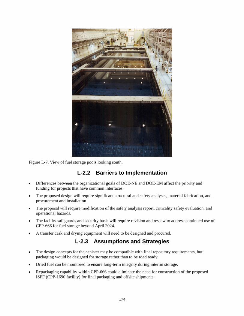
174
Figure L-7. View of fuel storage pools looking south.
L-2.2 Barriers to Implementation
• Differences between the organizational goals of DOE-NE and DOE-EM affect the priority and funding for projects that have common interfaces.
• The proposed design will require significant structural and safety analyses, material fabrication, and procurement and installation.
• The proposal will require modification of the safety analysis report, criticality safety evaluation, and operational hazards.
• The facility safeguards and security basis will require revision and review to address continued use of CPP-666 for fuel storage beyond April 2024.
• A transfer cask and drying equipment will need to be designed and procured.
L-2.3 Assumptions and Strategies
• The design concepts for the canister may be compatible with final repository requirements, but packaging would be designed for storage rather than to be road ready.
• Dried fuel can be monitored to ensure long-term integrity during interim storage.
• Repackaging capability within CPP-666 could eliminate the need for construction of the proposed ISFF (CPP-1690 facility) for final packaging and offsite shipments.
175
L-2.4 Packaging the Fuel
• A canister that can be purged and evacuated and that allows condition monitoring on a periodic basis will be required.
• Backfilling of a sealed canister design with inert gas provides the most effective prevention of loss of fuel integrity caused by corrosion.
• Use of existing approved basket designs saves design, review, and approval cost.
L-2.5 Regulatory Issues
• Installation of a drying system in the facility will require revision to the existing Permit to Construct for Air Emissions.
• As a minimum, an environmental checklist will be required to evaluate the environmental impact of the proposal.
L-2.6 Cost (Capital and Operating)
• Capital costs will include design and fabrication of the structural and process components.
• This option relies on the existing wet cask receiving capability at CPP-666. While this use is arguably transfer function and not wet storage, maintenance costs, including those for pool water quality, would be incurred until or unless other provisions are made for transfer, drying, and configuration of ATR SNF for dry storage.
L-2.7 Risk
• When compared to options that require construction of a new facility, the risk is reduced because the facility modifications for this proposal can be executed inside an enclosed building with limited weather effect on construction timelines.
• Performing facility modifications within an existing security perimeter increases costs due to the need for security personnel to oversee construction staff during installation.
• The maturity of the design is relatively high because it incorporates design concepts from existing facilities, making it low risk.
• Security risk is reduced by the building structure and minimization of the need to move fuel from this building to another for storage.
L-2.8 Complexity
• The steel plates can be fabricated using a water jet to cut the circular penetrations. Installation of the individual steel upper plates can be performed using existing equipment and integral component characteristics. Low complexity interlocking pieces bolted together for final structural integrity limits the number of special processes necessary for assembly.
• Depending on the future loading and decay heat of the fuel, active ventilation may be required. Tying into the existing ventilation system will add complexity to the design. Passive ventilation will be incorporated into the design.
L-2.9 Stakeholder Value

176
L-3. DISCRIMINATORS OF OPTION
L-3.1 Meet the Capability Gap
Assuming there are 1,000 ATR elements in pool storage at the moment that need to be moved to dry storage and a production rate of 105 elements per year between 2016 and 2050, the capacity needed would be 4,570 elements or 96 storage positions (assuming 48 elements per position). This option provides 180 dry storage positions and would offer capacity for an additional 4,070 elements. Assuming there are 3,000 EBR-II cans still present in the facility, racked in eight position buckets, the buckets could be stored in the proposed canisters three high (24 cans per canister), with canisters stored three deep. Fifty storage positions would be required to store the current EBR-II inventory. This would leave 34 storage positions available for other fuel.
If organizational facility ownership is not clarified and contract targets are not revised to reflect project priority, delays may occur when trying to meet the existing contract commitments.
As proposed, the facility would have capacity for ATR fuel production for at least 30 years, as well as being able to store the balance of the EBR-II driver until it can be processed.
Unfortunately, the proposed option does not assure complete conversion to dry storage by the year 2023.
L-3.2 Technical Complexity and Maturity of the Option
The design is fundamentally the same as storage systems used for the Ft. St. Vrain ISFSI and high-level waste glass facilities around the world. The plate and tube design does not require development of new technology to fabricate or install the structural equipment.
The proposed canister design can be effectively purged and vacuum dried more effectively than the design in use for IFSF. The fuels from CPP-666 are less degraded than those removed from CPP-603. It is a wet storage, meaning they can be dried and maintained in sealed canisters with minimal expectation of degradation. Periodic monitoring can be done using the purge and evacuation connections. The canister can be made to be compatible with other final repository designs.
Because the pool to be converted is integral to the CPP-666 facility, the proposed design uses the same equipment as was used in wet operations and is compatible. It is already certified to receive the ATR cask and other inter-facility casks. The ability to use multiple different baskets in the canister allows flexibility in the types of fuel that may be stored.
If all wet operations at CPP-666 were to be terminated, an ATR-compatible top-and-bottom loading cask will be needed to place canisters in the dry storage tubes.
L-3.3 Meet Stakeholder, Legal, and Regulatory Requirements
Achieving the goal of transfer of the SNF in CPP-666 from wet to dry storage by the year 2023 may be met using this approach. Stakeholders interested in minimizing the nuclear footprint of the site would welcome the avoidance of constructing a new facility.
L-3.4 Environment, Safety, and Health
If fuel storage is discontinued at CPP-666, it is likely there will be a direction to completely decommission the facility. There is a greater environmental impact to demolish CPP-666 and construct a new facility than to continue use of CPP-666 as a multiple use facility. The potential impact of dispersing the fuel presently stored there to multiple facilities increases the net hazard when compared to keeping the

177
fuel inside the building. The hazards of moving fuel from facility to facility create contamination and exposure hazards not expected in this design.
By keeping the packaging and storage of the fuel under one roof, the potential for personnel exposure and environmental release is reduced; therefore, this option has a higher safety status. The fact that the facility is at least 10 years newer than the other immediately available facility (CPP-603) and the equipment in use is accessible for maintenance (CRN-FS-901, 2 and 3 versus CRN-SF-01 and 101), implicitly increasing safety for fuel-handling by minimizing the risk to do maintenance.
This proposed option could have industrial safety impacts during the construction phase.
Cask drop could lead to canister damage and contamination of the pool. Assuming the building ventilation, pool filtration and ion exchange are operable, the personnel and environmental risk is negligible.
L-3.5 Schedule and Funding Limitations
Assuming that funding was available and that a protracted discussion was not the result of the environmental checklist/assessment, a first-estimate schedule suggests that design and installation could be completed within 18 months, although 2 years is not improbable for work in a secure nuclear facility.
The schedule is 12 to 18 months, depending on NEPA and funding challenges. Conversion could take longer than 18 months to complete due to funding limitations or regulatory obstacles.
Figure L-8. Option 11 timetable.
External Schedule Constraints
•Fun
ding
ava
ilabl
e•I
FSF
reac
hes c
apac
ity(1
6 AT
R SN
F / p
ort)
•ATR
Can
al a
t cap
acity
unle
ss S
NF sh
ips
•ISA
- al
l INL
SNF
out
of w
et st
orag
e by
en
d of
yea
r
•Ass
umed
last
ATR
SNF
gen
erat
ed(b
asis
of d
efin
ed sc
ope)
•Rep
osito
ry a
ccep
ts A
TR S
NF
2016 2017 2019 2020 2023 >> 2050 > 2055
•Res
ume
ship
ping
of A
TR S
NFto
CPP
-666
•NEP
A EA
take
s 6 m
onth
s•S
tart
des
ign
& a
naly
ses
•Beg
in in
stal
latio
n
•Rem
aini
ng A
TR S
NF d
ry st
ored
at A
TR
(afte
r coo
ling
at A
TR C
anal
)
Timetable for Option 12
178
L-3.6 Interfaces and Integration Requirements
At some point a resolution between DOE-EM and DOE-NE on cost sharing and responsibility would need to be achieved. The design and analysis would need to be performed with review and approval of the facility operator. Installation could be contracted through the facility operator.
L-3.7 Safeguards and Security
Use of the CPP-666 facility beyond April 2024 is NOT within the security plan. Possible changes in the safeguards and security requirements will have to be determined.
L-3.8 Near-Term Cost
Near-term costs appear to be mid-range. Creative use of existing infrastructure reduces the initial capital investment in the dry storage capability compared to options that build new facilities from the ground up, but the price is not competitive with options that employ existing dry storage. Considerable initial investment in planning and analysis would also be required, including a NEPA evaluation assumed to entail an environmental assessment.
L-3.9 Life-Cycle Cost
Overall, this option is high in cost, with schedule risk inherent to the need for planned shipments of fuels out of wet storage by the end of 2023 and the space limitations at the ATR canal without additional actions by the year 2020, constraining the proposed facility modifications anticipated to begin in 2020. Life-cycle cost includes both the initial costs identified as near-term cost and recurring costs accumulated over the life of the ATR SNF.
L-3.9.1 Recurring Costs
• Unloading of ATR elements from the ATR canal and loading and drying of storage canisters were considered, along with (modified) CPP-666 facility maintenance and competing near-term fuel-handling operations.
• There are enough existing buckets for 2,400 ATR elements in all 300 existing ports. If additional ports are used, additional buckets would be needed.
• Costs for transfer from storage to repository are not included, but are assumed to use CPP-666 packaging capability rather than ISFF.
The use of CPP-666 beyond April 2024 will also require evaluation for facility life extension. These costs were not defined or bounded in this rough estimate, and physical upgrades for security contribute significant financial risk to this option.
L-4. RECOMMENDATION FOR OPTION
Conversion of CPP-666 to provide dry storage capacity for ATR SNF is not a preferred option. The overall costs are large and the schedule risk is high due to competing near-term use of the CPP-666 facility for storage and transfer activities.

179
Appendix M
Discriminators and Screening Criteria

180
181
Appendix M
Discriminators and Screening Criteria Nine distinct discriminators, representative of the overall risk of a successful ATR SNF management
option, were identified to evaluate the different management options. Thirteen criteria were developed for the discriminators, which were further decomposed into 34 individual factors. Decomposition allowed better definition and improved discrimination between the relative risks of each option and the options’ ability to meet the criteria. The option discriminators, criteria, and factors for comparison of relative risk are presented in Table M-1.
With 12 options and multiple criteria, the impact of significant risks or barriers can be underestimated. Therefore, for pre-screening, the comparison criteria were consolidated into four general criteria of “Cost,” “Acceptability,” “Implementability,” and “Schedule.” All individual factors were mapped to the associated consolidated criterion and that information is shown in Table M2. The individual options were pre-screened and scored as they relate to the consolidated criteria and factors. The results of the pre-screening are presented in the body of the report. Tables M1 and M2 are color coded for easier tracking of individual factors to the option criteria and consolidated criteria.

182
Table M-1. Option discriminators, criteria, and factors for comparison of relative risk. Screening Criteria Mapped to Option Discriminators
Discriminators of Option Criteria Factors for Comparison of Relative Risk
1. Meet the capability gap
Capacity • Meets projected annual generation rates • Sustainable through 2050
Mission impact at ATR
• Minimizes impact to ATR operations • Supports long-term mission
2. Technical Technical feasibility
• Mature technology with limited difficulty to further mature • Minimal amount of technical issues
Operability • Minimize process/operating and maintenance complexity • Ease of startup and shutdown • Maximize probability of consistently meeting target production
rates 3. Meet stakeholder,
legal, and regulatory requirements
Stakeholder acceptance
• Achieve acceptance from local/regional stakeholders • Achieve acceptance from external stakeholders
4. Environment, safety, and health
Regulatory compliance
• Complies with ISA through 2023 • Complies with existing NEPA documentation
Safety • Limit safety hazard issues to the public • Limit safety hazard issues to the environment • Limit safety hazard issues to the workers
5. Schedule and funding limitations
Schedule • Maximize throughput • Delay large capital investments • Complies with ISA through 2023 • Minimizes impact to ATR operations • Sustainable through 2050 • Annual funding to support implementation
6. Interfaces and integration requirements
Management complexity
• Limit external interfaces • Limit loss of management control
7. Safeguards and security
Security • Easily achieved security requirements • Limit security impacts to operating costs • Limit security impacts to investment costs
8. Near-term cost maps to consolidated life-cycle cost but not to a discreet discriminator
Near-term cost
• Near-term costs through 2023 are not significant • Cost is reflective of utilizing INL’s existing capacity • Some minor facility mods may be required
9. Life-cycle cost Life-cycle cost
• Requires high annual operation and maintenance costs • Requires a line item project • Minimizes total project cost • Minimizes peak year cost
The 34 factors that are color-coded in Table M-1 are presented in Table M-2 for the consolidated
criteria of cost, acceptability, implementability, and schedule.

183
Table M-2. Consolidated criteria of cost, acceptability, implementability, and schedule. Options Pre-Screening Consolidated Criteria Descriptions
Consolidated Criteria Factors for Comparison of Relative Risk Cost – Near-Term and Life-Cycle
• Near-term costs through 2023 are not significant • Cost is reflective of using INL’s existing capacity • Some minor facility modifications may be required • Requires high annual operation and maintenance costs • Requires a line item project • Minimizes total project cost • Minimizes peak year cost
Acceptability – Regulatory Compliance, Stakeholder Acceptance, Capacity, Mission Impact at ATR, and Safety
• Complies with ISA through 2023 • Complies with existing NEPA documentation • Achieves acceptance from local/regional stakeholders • Achieves acceptance from external stakeholders • Meets projected annual generation rates • Sustainable through 2050 • Minimizes impact to ATR operations • Supports long-term mission • Limits safety hazard issues to the public • Limits safety hazard issues to the environment • Limits safety hazard issues to the workers
Implementability – Technical Feasibility, Management Complexity, Operability, and Security
• Mature technology with limited difficulty to further mature • Minimal amount of technical issues • Minimizes process/operating and maintenance complexity • Ease of startup and shutdown • Maximizes probability of consistently meeting target production rates • Limits external interfaces • Limits loss of management control • Easily achieved security requirements • Limits security impacts to operating costs • Limits security impacts to investment costs
Schedule • Maximizes throughput • Delays large capital investments • Complies with ISA through 2023 • Minimizes impact to ATR operations • Sustainable through 2050 • Annual funding to support implementation