ahd/ahs series air-operated double-diaphragm pumps · 2 3 the almatec® high pressure diaphragm...
TRANSCRIPT
HIGH PRESSURE DIAPHRAGM PUMPS MADE OF PLASTIC AND STAINLESS STEEL
Where Innovation Flows
almatec.de
AIR-OPERATED DOUBLE-DIAPHRAGM PUMPS
CONSTRUCTED OF POYETHYLENE
FOR HIGH-PRESSURE APPLICATIONS UP TO 15 BAR (218 PSIG)
AHD/AHS SERIESAir-Operated Double-Diaphragm Pumps
32
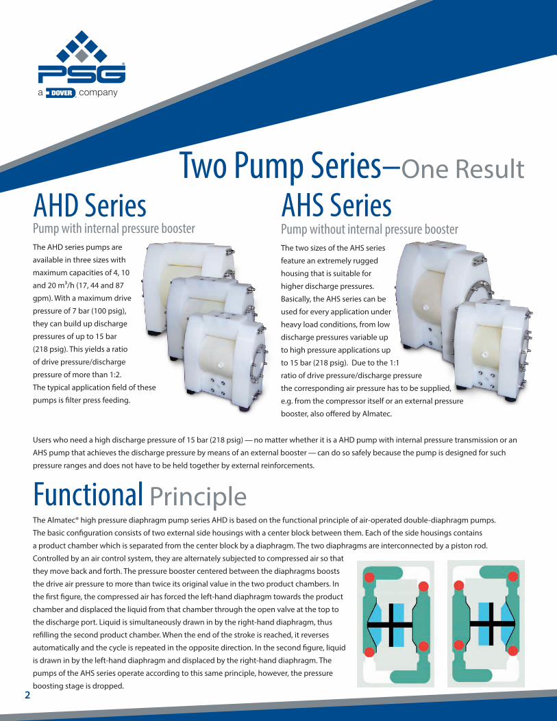
The Almatec® high pressure diaphragm pump series AHD is based on the functional principle of air-operated double-diaphragm pumps.
The basic configuration consists of two external side housings with a center block between them. Each of the side housings contains
a product chamber which is separated from the center block by a diaphragm. The two diaphragms are interconnected by a piston rod.
Controlled by an air control system, they are alternately subjected to compressed air so that
they move back and forth. The pressure booster centered between the diaphragms boosts
the drive air pressure to more than twice its original value in the two product chambers. In
the first figure, the compressed air has forced the left-hand diaphragm towards the product
chamber and displaced the liquid from that chamber through the open valve at the top to
the discharge port. Liquid is simultaneously drawn in by the right-hand diaphragm, thus
refilling the second product chamber. When the end of the stroke is reached, it reverses
automatically and the cycle is repeated in the opposite direction. In the second figure, liquid
is drawn in by the left-hand diaphragm and displaced by the right-hand diaphragm. The
pumps of the AHS series operate according to this same principle, however, the pressure
boosting stage is dropped.
Two Pump Series–One Result
Functional Principle
Users who need a high discharge pressure of 15 bar (218 psig) — no matter whether it is a AHD pump with internal pressure transmission or an
AHS pump that achieves the discharge pressure by means of an external booster — can do so safely because the pump is designed for such
pressure ranges and does not have to be held together by external reinforcements.
AHD SeriesPump with internal pressure boosterThe AHD series pumps are
available in three sizes with
maximum capacities of 4, 10
and 20 m³/h (17, 44 and 87
gpm). With a maximum drive
pressure of 7 bar (100 psig),
they can build up discharge
pressures of up to 15 bar
(218 psig). This yields a ratio
of drive pressure/discharge
pressure of more than 1:2.
The typical application field of these
pumps is filter press feeding.
AHS SeriesPump without internal pressure boosterThe two sizes of the AHS series
feature an extremely rugged
housing that is suitable for
higher discharge pressures.
Basically, the AHS series can be
used for every application under
heavy load conditions, from low
discharge pressures variable up
to high pressure applications up
to 15 bar (218 psig). Due to the 1:1
ratio of drive pressure/discharge pressure
the corresponding air pressure has to be supplied,
e.g. from the compressor itself or an external pressure
booster, also offered by Almatec.
32
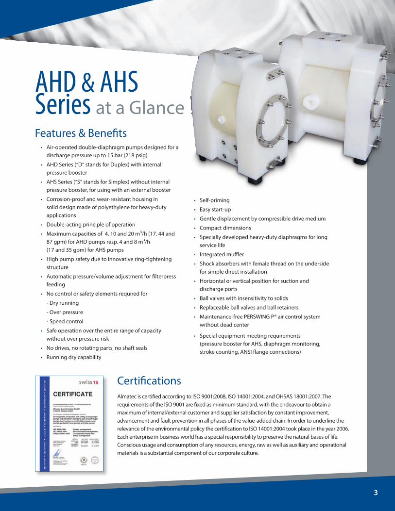
AHD & AHS Series at a Glance
• Air-operated double-diaphragm pumps designed for a discharge pressure up to 15 bar (218 psig)
• AHD Series (“D“ stands for Duplex) with internal pressure booster
• AHS Series (“S“ stands for Simplex) without internal pressure booster, for using with an external booster
• Corrosion-proof and wear-resistant housing in solid design made of polyethylene for heavy-duty applications
• Double-acting principle of operation
• Maximum capacities of 4, 10 and 20 m³/h (17, 44 and 87 gpm) for AHD pumps resp. 4 and 8 m³/h
(17 and 35 gpm) for AHS pumps
• High pump safety due to innovative ring-tightening structure
• Automatic pressure/volume adjustment for filterpress feeding
• No control or safety elements required for
- Dry running
- Over pressure
- Speed control
• Safe operation over the entire range of capacity without over pressure risk
• No drives, no rotating parts, no shaft seals
• Running dry capability
• Self-priming
• Easy start-up
• Gentle displacement by compressible drive medium
• Compact dimensions
• Specially developed heavy-duty diaphragms for long service life
• Integrated muffler
• Shock absorbers with female thread on the underside for simple direct installation
• Horizontal or vertical position for suction and discharge ports
• Ball valves with insensitivity to solids
• Replaceable ball valves and ball retainers
• Maintenance-free PERSWING P® air control system without dead center
• Special equipment meeting requirements (pressure booster for AHS, diaphragm monitoring,
stroke counting, ANSI flange connections)
Features & Benefits
CertificationsAlmatec is certified according to ISO 9001:2008, ISO 14001:2004, and OHSAS 18001:2007. The requirements of the ISO 9001 are fixed as minimum standard, with the endeavour to obtain a maximum of internal/external customer and supplier satisfaction by constant improvement, advancement and fault prevention in all phases of the value-added chain. In order to underline the relevance of the environmental policy the certification to ISO 14001:2004 took place in the year 2006. Each enterprise in business world has a special responsibility to preserve the natural bases of life. Conscious usage and consumption of any resources, energy, raw as well as auxiliary and operational materials is a substantial component of our corporate culture.
54
Code SystemSize, port dimension
AHD 25 E T T - C
Diaphragm material:E = EPDMN = NBRT = PTFE/EPDM compound
Optional equipment:BO = Pressure booster (AHS only)C = Stroke countingD = Diaphragm monitoringW = ANSI flange connections
Wetted housing material:E = PE UHMW
Ball valve material:E = EPDMN = NBRT = PTFE
AHD seriesAHS series
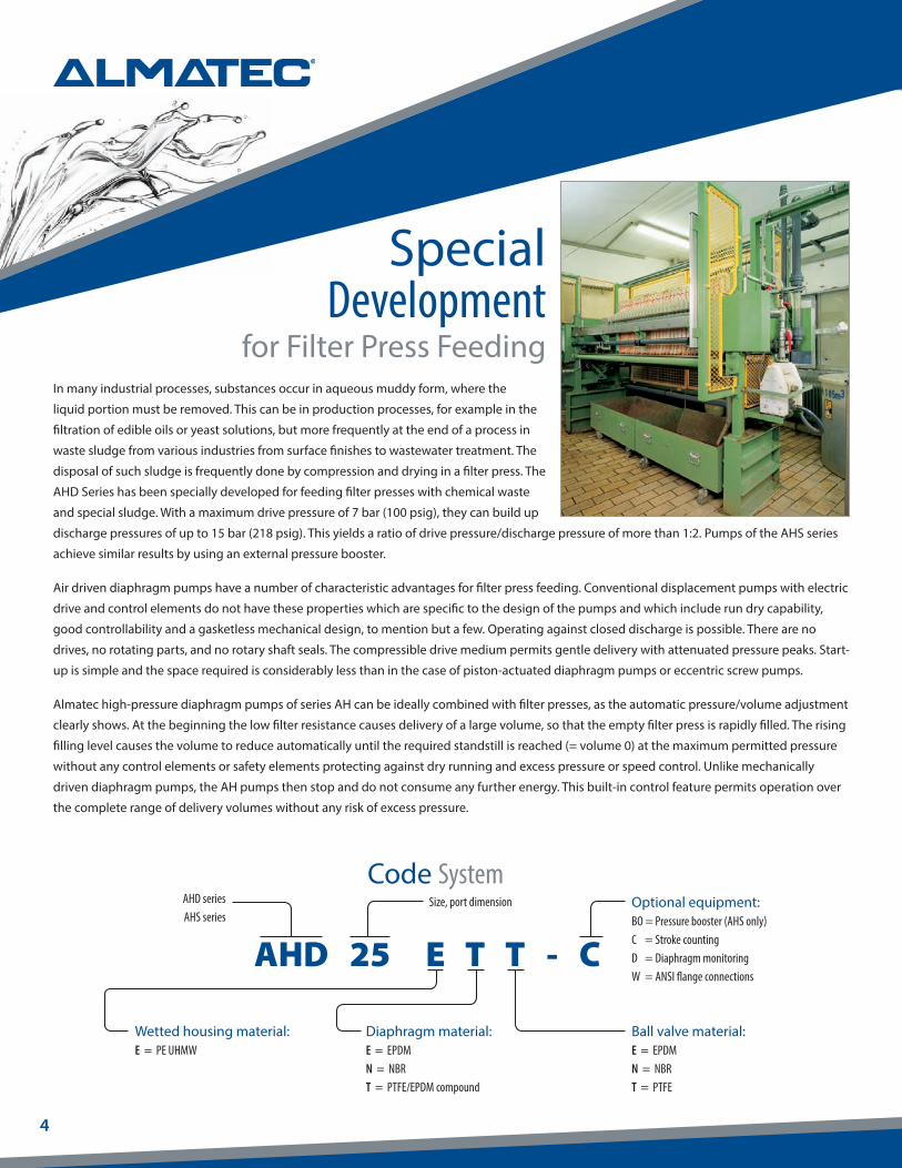
In many industrial processes, substances occur in aqueous muddy form, where the
liquid portion must be removed. This can be in production processes, for example in the
filtration of edible oils or yeast solutions, but more frequently at the end of a process in
waste sludge from various industries from surface finishes to wastewater treatment. The
disposal of such sludge is frequently done by compression and drying in a filter press. The
AHD Series has been specially developed for feeding filter presses with chemical waste
and special sludge. With a maximum drive pressure of 7 bar (100 psig), they can build up
discharge pressures of up to 15 bar (218 psig). This yields a ratio of drive pressure/discharge pressure of more than 1:2. Pumps of the AHS series
achieve similar results by using an external pressure booster.
Air driven diaphragm pumps have a number of characteristic advantages for filter press feeding. Conventional displacement pumps with electric
drive and control elements do not have these properties which are specific to the design of the pumps and which include run dry capability,
good controllability and a gasketless mechanical design, to mention but a few. Operating against closed discharge is possible. There are no
drives, no rotating parts, and no rotary shaft seals. The compressible drive medium permits gentle delivery with attenuated pressure peaks. Start-
up is simple and the space required is considerably less than in the case of piston-actuated diaphragm pumps or eccentric screw pumps.
Almatec high-pressure diaphragm pumps of series AH can be ideally combined with filter presses, as the automatic pressure/volume adjustment
clearly shows. At the beginning the low filter resistance causes delivery of a large volume, so that the empty filter press is rapidly filled. The rising
filling level causes the volume to reduce automatically until the required standstill is reached (= volume 0) at the maximum permitted pressure
without any control elements or safety elements protecting against dry running and excess pressure or speed control. Unlike mechanically
driven diaphragm pumps, the AH pumps then stop and do not consume any further energy. This built-in control feature permits operation over
the complete range of delivery volumes without any risk of excess pressure.
SpecialDevelopment
for Filter Press Feeding
54
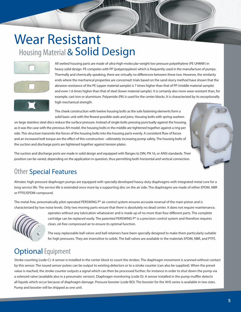
All wetted housing parts are made of ultra-high-molecular-weight low pressure polyethylene (PE UHMW) in
heavy solid design. PE competes with PP (polypropylene) which is frequently used in the manufacture of pumps.
Thermally and chemically speaking, there are virtually no differences between these two. However, the similarity
ends where the mechanical properties are concerned: trials based on the sand-slurry method have shown that the
abrasion resistance of the PE (upper material sample) is 7 times higher than that of PP (middle material sample)
and even 1.6 times higher than that of steel (lower material sample). It is certainly also more wear-resistant than, for
example, cast iron or aluminium. Polyamide (PA) is used for the center blocks. It is characterized by its exceptionally
high mechanical strength.
The cheek construction with twelve housing bolts as the sole fastening elements form a
solid basic unit with the fewest possible seals and joins. Housing bolts with spring washers
on large stainless steel discs reduce the surface pressure. Instead of single bolts pressing punctually against the housing,
as it was the case with the previous AH model, the housing bolts in the middle are tightened together against a ring per
side. This structure transmits the forces of the housing bolts into the housing parts evenly. A consistent flow of forces
and an increased bolt torque are the effect of this construction –ultimately increasing pump safety. The housing bolts of
the suction and discharge ports are tightened together against tension plates.
The suction and discharge ports are made in solid design and equipped with flanges to DIN, PN 16, or ANSI standards. Their
position can be varied, depending on the application in question, thus permitting both horizontal and vertical connection.
Other Special FeaturesAlmatec high-pressure diaphragm pumps are equipped with specially developed heavy-duty diaphragms with integrated metal core for a
long service life. The service life is extended once more by a supporting disc on the air side. The diaphragms are made of either EPDM, NBR
or PTFE/EPDM-compound.
The metal-free, pneumatically pilot-operated PERSWING P® air control system ensures accurate reversal of the main piston and is
characterized by low noise levels. Only two moving parts ensure that there is absolutely no dead center. It does not require main tenance,
operates without any lubrication whatsoever and is made up of no more than four different parts. The complete
cartridge can be replaced easily. The patented PERSWING P® is a precision control system and therefore requires
clean, oil-free compressed air to ensure its optimal function.
The easy replaceable ball valves and ball retainers have been specially designed to make them particularly suitable
for high pressures. They are insensitive to solids. The ball valves are available in the materials EPDM, NBR, and PTFE.
Optional EquipmentStroke counting (code C): A sensor is installed in the center block to count the strokes. The diaphragm movement is scanned without contact
by this sensor. The issued sensor pulses can be output to existing detectors or to a stroke counter (can also be supplied). When the preset
value is reached, the stroke counter outputs a signal which can then be processed further, for instance in order to shut down the pump via
a solenoid valve (available also in a pneumatic version). Diaphragm monitoring (code D): A sensor installed in the pump muffler detects
all liquids which occur because of diaphragm damage. Pressure booster (code BO): The booster for the AHS series is available in two sizes.
Pump and booster will be shipped as one unit.
Wear ResistantHousing Material & Solid Design

76
Spare Part KitsSpare part kits S for pumps of the AHD/AHS series are compiled for single-shift operation (8 hours per day). These kits ensure that the correct replacement parts are always available in the required quantities. This helps to avoid production stoppages and ensures that the Almatec pumps are always ready for action. Besides, it is cheaper to buy spare parts as a kit than individually.
The standard configuration of the suction and discharge ports are according to the illustration: Discharge port to the top, suction port forward.
Technical Data AHD Series AHS Series
Pump size AHD 15 AHD 25 AHD 40 AHS 15 AHS 25Dimensions: Width Depth Height
mm (in.)312 (12.3)177 (7.0)
336 (13.2)
422 (16.6)256 (10.1)412 (16.2)
539 (21.2)291 (11.5)544 (21.4)
266 (10.5)177 (7.0)
336 (13.2)
336 (13.2)256 (10.1)412 (16.2)
Flange connections Air connection
DIN or ANSIBSP
15 (1/2")1/4"
25 (1")1/2"
40 (1-1/2")1/2"
15 (1/2")1/4“
25 (1")1/4“
Weight: kg (lb) 11 (24) 24 (53) 53 (117) 9 (20) 19 (42))
Max. particle size of solids mm (in.) 4 (0.16) 5 (0.20) 8 (0.31) 4 (0.16) 5 (0.20)
Suction lift, dry:- EPDM/NBR ball valves- PTFE ball valves
Suction lift, wet
mWC (ft)2 (6.6)
1.5 (4.9)9.5 (31.2)
3.5 (11.5)2 (6.6)
9.5 (31.2)
3.5 (11.5)2 (6.6)
9.5 (31.2)
2 (6.6)1.5 (4.9)
9.5 (31.2)
2.5 (8.2)1.5 (4.9)
9.5 (31.2)
Max. driving and operating pressure
bar (psig) 7 (100) 7 (100) 7 (100) 15 (218) 15 (218)
Max. operating temperature °C (F) 70 (158) 70 (158) 70 (158) 70 (158) 70 (158)
76
0
0
0
7 bar
6 bar
5 bar
4 bar
3 bar
2 bar
0 0.5 1 1.5 2 2.5 3 3.5 4
2.2 4.4 6.6 8.8 11 13.2 15.4 17.6
AHD 15
(m³/h)
(USGPM)
(m³/h)
(USGPM)
(m³/h)
(USGPM)
4.4 8.8 13.2 17.6 22 26.4 30.8 35.2 39.6 44
AHD 257 bar
6 bar
4 bar
5 bar
3 bar
2 bar
0.6
0.8
1
1.2 1.4
1.6
0 1 2 3 4 5 6 7 8 9 10
1.8
8.8 17.6 26.4 35.2 44 52.8 61.6 70.5 79.3 88.1
AHD 407 bar
6 bar
5 bar
4 bar
3 bar
2 bar
1.4 1.6
1.8
2 2.2
2.4
2.6
0 2 4 6 8 10 12 14 16 18 20
PSIG mWC
140
150
120
130
100
110
80
90
60
40
20
10
70
50
30
0
220
200
180
160
140
120
100
80
60
40
20
0
0.2 0.6
0.4
0.2 0.6
0.4
PSIG mWC
140
150
120
130
100
110
80
60
70
90
40
50
20
10
30
0
220
200
180
160
140
120
100
80
60
40
20
0
PSIG mWC
150
130
140
110
120
90
100
80
60
70
40
50
20
30
10
0
220
200
180
160
140
120
100
80
60
40
20
0
Flow Rate
Tota
l Hea
d
Flow Rate
Tota
l Hea
d
Flow Rate
Tota
l Hea
d
7 bar
6 bar
5 bar
4 bar
3 bar
2 bar
AHS 15 0.3
0.4
7 bar
6 bar
5 bar
4 bar
3 bar
2 bar
0.2
0.4
0.3 0.5
0.6
7 bar
6 bar
5 bar
4 bar
3 bar
2 bar
0.5
0.6 0.7
0.8
0
0 0.5 1 1.5 2 2.5 3 3.5 4
2.2 4.4 6.6 8.8 11 13.2 15.4 17.6
(m³/h)
(USGPM)
Flow Rate
PSIG mWC
140
150
120
130
100
110
80
90
60
40
20
10
70
50
30
0
220
200
180
160
140
120
100
80
60
40
20
0
Tota
l Hea
d
PSIG mWC
60
70
40
50
20
10
30
0
30
40
50
60
20
10
0
Tota
l Hea
d
70
80
90
100
0 1 2 3 4 5 6 7 8
0 4.4 8.8 13.2 17.6 22 26.4 30.8 35.2
(m³/h)
(USGPM)
Flow Rate
0 1 2 3 4 5 6 7 8
0 4.4 8.8 13.2 17.6 22 26.4 30.8 35.2
(m³/h)
(USGPM)
Flow Rate
PSIG mWC
60
70
40
50
20
10
30
0
30
40
50
60
20
10
0
Tota
l Hea
d
70
80
90
100
AHS 25with External Booster
AHS 25
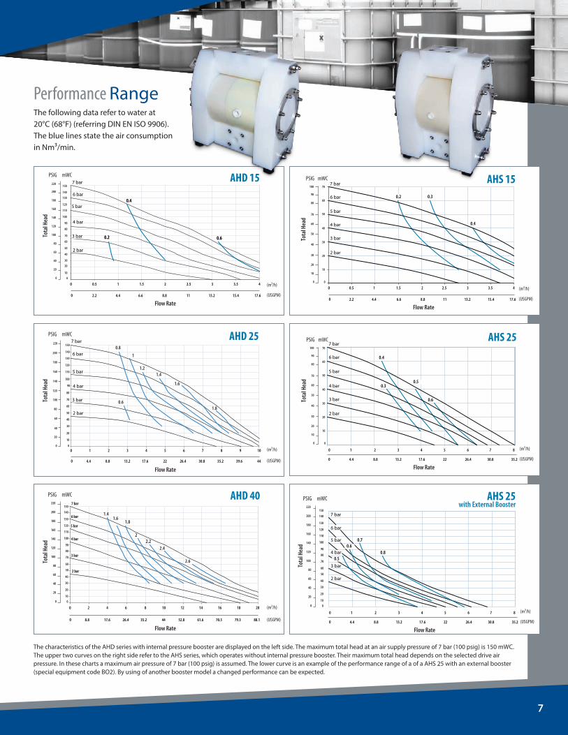
The characteristics of the AHD series with internal pressure booster are displayed on the left side. The maximum total head at an air supply pressure of 7 bar (100 psig) is 150 mWC. The upper two curves on the right side refer to the AHS series, which operates without internal pressure booster. Their maximum total head depends on the selected drive air pressure. In these charts a maximum air pressure of 7 bar (100 psig) is assumed. The lower curve is an example of the performance range of a of a AHS 25 with an external booster (special equipment code BO2). By using of another booster model a changed performance can be expected.
7 bar
6 bar
5 bar
4 bar
3 bar
2 bar
AHS 15 0.3
0.4
7 bar
6 bar
5 bar
4 bar
3 bar
2 bar
0.2
0.4
0.3 0.5
0.6
7 bar
6 bar
5 bar
4 bar
3 bar
2 bar
0.5
0.6 0.7
0.8
0
0 0.5 1 1.5 2 2.5 3 3.5 4
2.2 4.4 6.6 8.8 11 13.2 15.4 17.6
(m³/h)
(USGPM)
Flow Rate
PSIG mWC
140
150
120
130
100
110
80
90
60
40
20
10
70
50
30
0
220
200
180
160
140
120
100
80
60
40
20
0
Tota
l Hea
d
PSIG mWC
60
70
40
50
20
10
30
0
30
40
50
60
20
10
0
Tota
l Hea
d
70
80
90
100
0 1 2 3 4 5 6 7 8
0 4.4 8.8 13.2 17.6 22 26.4 30.8 35.2
(m³/h)
(USGPM)
Flow Rate
0 1 2 3 4 5 6 7 8
0 4.4 8.8 13.2 17.6 22 26.4 30.8 35.2
(m³/h)
(USGPM)
Flow Rate
PSIG mWC
60
70
40
50
20
10
30
0
30
40
50
60
20
10
0
Tota
l Hea
d
70
80
90
100
AHS 25with External Booster
AHS 25
7 bar
6 bar
5 bar
4 bar
3 bar
2 bar
AHS 15 0.3
0.4
7 bar
6 bar
5 bar
4 bar
3 bar
2 bar
0.2
0.4
0.3 0.5
0.6
7 bar
6 bar
5 bar
4 bar
3 bar
2 bar
0.5
0.6 0.7
0.8
0
0 0.5 1 1.5 2 2.5 3 3.5 4
2.2 4.4 6.6 8.8 11 13.2 15.4 17.6
(m³/h)
(USGPM)
Flow Rate
PSIG mWC
140
150
120
130
100
110
80
90
60
40
20
10
70
50
30
0
220
200
180
160
140
120
100
80
60
40
20
0
Tota
l Hea
d
PSIG mWC
60
70
40
50
20
10
30
0
30
40
50
60
20
10
0
Tota
l Hea
d
70
80
90
100
0 1 2 3 4 5 6 7 8
0 4.4 8.8 13.2 17.6 22 26.4 30.8 35.2
(m³/h)
(USGPM)
Flow Rate
0 1 2 3 4 5 6 7 8
0 4.4 8.8 13.2 17.6 22 26.4 30.8 35.2
(m³/h)
(USGPM)
Flow Rate
PSIG mWC
60
70
40
50
20
10
30
0
30
40
50
60
20
10
0
Tota
l Hea
d
70
80
90
100
AHS 25with External Booster
AHS 25
0
0
0
7 bar
6 bar
5 bar
4 bar
3 bar
2 bar
0 0.5 1 1.5 2 2.5 3 3.5 4
2.2 4.4 6.6 8.8 11 13.2 15.4 17.6
AHD 15
(m³/h)
(USGPM)
(m³/h)
(USGPM)
(m³/h)
(USGPM)
4.4 8.8 13.2 17.6 22 26.4 30.8 35.2 39.6 44
AHD 257 bar
6 bar
4 bar
5 bar
3 bar
2 bar
0.6
0.8
1
1.2 1.4
1.6
0 1 2 3 4 5 6 7 8 9 10
1.8
8.8 17.6 26.4 35.2 44 52.8 61.6 70.5 79.3 88.1
AHD 407 bar
6 bar
5 bar
4 bar
3 bar
2 bar
1.4 1.6
1.8
2 2.2
2.4
2.6
0 2 4 6 8 10 12 14 16 18 20
PSIG mWC
140
150
120
130
100
110
80
90
60
40
20
10
70
50
30
0
220
200
180
160
140
120
100
80
60
40
20
0
0.2 0.6
0.4
0.2 0.6
0.4
PSIG mWC
140
150
120
130
100
110
80
60
70
90
40
50
20
10
30
0
220
200
180
160
140
120
100
80
60
40
20
0
PSIG mWC
150
130
140
110
120
90
100
80
60
70
40
50
20
30
10
0
220
200
180
160
140
120
100
80
60
40
20
0
Flow Rate
Tota
l Hea
d
Flow Rate
Tota
l Hea
d
Flow Rate
Tota
l Hea
d
0
0
0
7 bar
6 bar
5 bar
4 bar
3 bar
2 bar
0 0.5 1 1.5 2 2.5 3 3.5 4
2.2 4.4 6.6 8.8 11 13.2 15.4 17.6
AHD 15
(m³/h)
(USGPM)
(m³/h)
(USGPM)
(m³/h)
(USGPM)
4.4 8.8 13.2 17.6 22 26.4 30.8 35.2 39.6 44
AHD 257 bar
6 bar
4 bar
5 bar
3 bar
2 bar
0.6
0.8
1
1.2 1.4
1.6
0 1 2 3 4 5 6 7 8 9 10
1.8
8.8 17.6 26.4 35.2 44 52.8 61.6 70.5 79.3 88.1
AHD 407 bar
6 bar
5 bar
4 bar
3 bar
2 bar
1.4 1.6
1.8
2 2.2
2.4
2.6
0 2 4 6 8 10 12 14 16 18 20
PSIG mWC
140
150
120
130
100
110
80
90
60
40
20
10
70
50
30
0
220
200
180
160
140
120
100
80
60
40
20
0
0.2 0.6
0.4
0.2 0.6
0.4
PSIG mWC
140
150
120
130
100
110
80
60
70
90
40
50
20
10
30
0
220
200
180
160
140
120
100
80
60
40
20
0
PSIG mWC
150
130
140
110
120
90
100
80
60
70
40
50
20
30
10
0
220
200
180
160
140
120
100
80
60
40
20
0
Flow Rate
Tota
l Hea
d
Flow Rate
Tota
l Hea
d
Flow Rate
Tota
l Hea
d
Performance RangeThe following data refer to water at20°C (68°F) (referring DIN EN ISO 9906). The blue lines state the air consumption in Nm³/min.

Almatec Maschinenbau GmbHCarl-Friedrich-Gauß-Straße 5
47475 Kamp-Lintfort, GermanyT: +49 (0) 2842/961-0
F: +49 (0) 2842/961-40 [email protected]
almatec.de
Authorized PSG Partner:
Where Innovation Flows
PSG® reserves the right to modify the information and illustrations contained in this document without prior notice. This is a non-contractual document. 06-2016
Copyright © 2016 PSG®, a Dover company ALM-50000-C-03