instructions – parts list air-operated 819.6900 diaphragm
TRANSCRIPT

For fluid transfer applications. For professional use only.100 psi; 0.7 MPa; 7 bar Maximum Fluid Working Pressure100 psi; 0.7 MPa; 7 bar Maximum Air Input Pressure
POLYPROPYLENE, AND PVDF
VERDERAIR VA 15ACETAL* AND CONDUCTIVE POLYPROPYLENE*
VERDERAIR VA 15
ALUMINUM* AND STAINLESS STEEL*
VERDERAIR VA 20*See page 3 for ATEX information.
Patents Pending
Important Safety InstructionsRead all warnings and instructions in this manual. Save these instructions.
INSTRUCTIONS – PARTS LIST
Air-Operated Diaphragm Pumps
819.6900Rev. ZAS
EN
9065A
ti22128a9246A
VERDERAIR VA 15
VERDERAIR VA 20

2 819.6900
Table of ContentsTable of Contents . . . . . . . . . . . . . . . . . . . . . . . . . . 2Configuration Number Matrix . . . . . . . . . . . . . . . . . 3Symbols . . . . . . . . . . . . . . . . . . . . . . . . . . . . . . . . . . 4Installation . . . . . . . . . . . . . . . . . . . . . . . . . . . . . . . . 6Operation . . . . . . . . . . . . . . . . . . . . . . . . . . . . . . . . 12Maintenance . . . . . . . . . . . . . . . . . . . . . . . . . . . . . . 13Troubleshooting . . . . . . . . . . . . . . . . . . . . . . . . . . 14Service . . . . . . . . . . . . . . . . . . . . . . . . . . . . . . . . . . 15VERDERAIR VA 15 and VERDERAIR VA 20
Repair Kits . . . . . . . . . . . . . . . . . . . . . . . . . . . . 22VERDERAIR VA 15 and VERDERAIR VA 20
Common parts . . . . . . . . . . . . . . . . . . . . . . . . . 24
VERDERAIR VA 15 Parts Drawing . . . . . . . . . . . . 26VERDERAIR VA 15 Fluid Section Parts List . . . . 27
VERDERAIR VA 15 Fluid Section Parts List . . . 28VERDERAIR VA 20 Parts Drawing . . . . . . . . . . 29
VERDERAIR VA 20 Fluid Section Parts List . . . . 30Torque Sequence . . . . . . . . . . . . . . . . . . . . . . . . . . 32VERDERAIR VA 15 Technical Data . . . . . . . . . . . . 33VERDERAIR VA 20 Technical Data . . . . . . . . . . . . 35VERDERAIR VA 20 Dimensions . . . . . . . . . . . . . . 36VERDERAIR VA 15 and VA 20
Performance Charts . . . . . . . . . . . . . . . . . . 37VERDERAIR VA 15 and VA 20
Performance Charts . . . . . . . . . . . . . . . . . . 38

819.6900 3
Configuration Number MatrixCheck the identification plate (ID) for the Configuration Number of your pump. Use the following matrix to define the components of your pump.
Sample Configuration Number: VA15PP PP SP TF TB 00
NOTE: Some combinations are not possible. Please check with your local supplier or www.verderair.com.
*
ATEX T-code rating is dependent on the temperature of the fluid being pumped. Fluid temperature is limited by the materials of the pump interior wetted parts. See Technical Data for the maximum fluid operating temperature for your specific pump model.
VA15 P P PP SP TF TB 00Pump Model Fluid Section Air Section Check Valve Balls Diaphragms Connections Options
Pump Model(1 and 2) Fluid Section Material (3) Air Section Material (4) Check Valve Material (5) Check Valve Balls (6)
VA15 C Conductive Polypropylene*
P Polypropylene AC Acetal BN Buna–N
D Acetal* KY PVDF HY TPE
K PVDF PP Polypropylene SP Santoprene
P Polypropylene SS 316 Stainless Steel SS 316 Stainless Steel
VA20 A Aluminum* TF PTFE
S Stainless Steel* VT FKM Fluoroelastomer
Diaphragm (7) Connections (8) Options (9)
BN Buna–N TB Threaded BSP 00 Standard
GE Geolast TN Threaded NPT OD Open Down Inlet Manifold
HY TPE RE Remote
SP Santoprene SM Split Manifold
TF PTFE/Urethane, 2-Piece
TO PTFE – 1–Piece
VT FKM Fluoroelastomer
II 2 GDEx h IIC 66°C...135°C GbEx h IIIC T135°C Db

4 819.6900
SymbolsWarning Symbol Caution Symbol
WarningThis symbol alerts you to the possibility of serious injury or death if you do not follow the instructions.
CautionThis symbol alerts you to the possibility of damage to or destruction of equipment if you do not follow the instructions.
Warning
INSTRUCTIONS
EQUIPMENT MISUSE HAZARD
Equipment misuse can cause the equipment to rupture or malfunction and result in serious injury.
• This equipment is for professional use only.
• Read all instruction manuals, tags, and labels before operating the equipment.
• Use the equipment only for its intended purpose. If you are not sure, call your VERDER distributor.
• Do not alter or modify this equipment. Use only genuine VERDER parts and accessories.
• Check equipment daily. Repair or replace worn or damaged parts immediately.
• Do not exceed the maximum working pressure of the lowest rated component in your system. This equipment has a 100 psi; 0.7 MPa (7 bar) maximum working pressure at 100 psi; 0.7 MPa (7 bar) maximum incoming air pressure.
• Use fluids and solvents that are compatible with the equipment wetted parts. Refer to the Technical Data section of all equipment manuals. Read the fluid and solvent manufacturer’s warnings.
• Route hoses away from traffic areas, sharp edges, moving parts, and hot surfaces. Do not expose VERDER hoses to temperatures above 180°F (82°C) or below –40°C (–40°C).
• Wear hearing protection when operating this equipment.
• Do not lift pressurized equipment.
• Comply with all applicable local, state, and national fire, electrical, and safety regulations.
• Do not use 1.1.1-trichloroethane, methylene chloride, other halogenated hydrocarbon solvents or fluids containing such solvents in pressurized aluminum equipment. Such use could result in a chemical reaction, with the possibility of explosion.

819.6900 5
WarningTOXIC FLUID HAZARD
Hazardous fluid or toxic fumes can cause serious injury or death if splashed in the eyes or on the skin, inhaled, or swallowed.
• Know the specific hazards of the fluid you are using.
• Do not lift a pump under pressure. If dropped, the fluid section may rupture. Always follow the Pressure Relief Procedure on page 12 before lifting the pump.
• Store hazardous fluid in an approved container. Dispose of hazardous fluid according to all local, state, and national guidelines.
• Always wear protective eyewear, gloves, clothing, and respirator as recommended by the fluid and solvent manufacturer.
• Pipe and dispose of the exhaust air safely, away from people, animals, and food handling areas. If the diaphragm fails, the fluid is exhausted along with the air. Read Air Exhaust Ventilation on page 8.
• Never use an acetal pump to pump acids. Take precautions to avoid acid or acid fumes from contacting the pump housing exterior. Stainless steel parts will be damaged by exposure to acid spills and fumes.
FIRE AND EXPLOSION HAZARD
Improper grounding, poor ventilation, open flames, or sparks can cause a hazardous condition and result in a fire or explosion and serious injury.
• Ground the equipment. Refer to Grounding on page 10.
• Never use a non–conductive polypropylene or PVDF pump with non-conductive flammable fluids as specified by your local fire protection code. Refer to Grounding on page 10 for additional information. Consult your fluid supplier to determine the conductivity or resistivity of your fluid.
• If there is any static sparking or you feel an electric shock while using this equipment, stop pumping immediately. Do not use the equipment until you identify and correct the problem.
• Provide fresh air ventilation to avoid the buildup of flammable fumes from solvents or the fluid being pumped.
• Pipe and dispose of the exhaust air safely, away from all sources of ignition. If the diaphragm fails, the fluid is exhausted along with the air. Read Air Exhaust Ventilation on page 8.
• Keep the work area free of debris, including solvent, rags, and gasoline.
• Electrically disconnect all equipment in the work area.
• Extinguish all open flames or pilot lights in the work area.
• Do not smoke in the work area.
• Do not turn on or off any light switch in the work area while operating or if fumes are present.
• Do not operate a gasoline engine in the work area.

6 819.6900
InstallationGeneral Information• The Typical Installations in Fig. 2 are only guides for
selecting and installing system components. Contact your VERDER distributor for assistance in planning a system to suit your needs.
• Always use Genuine VERDER Parts and Accessories.
• Use a compatible, liquid thread sealant on all male threads. Tighten all connections firmly to avoid air or fluid leaks.
Tightening Threaded Fasteners Before First UseBefore using the pump for the first time, check and retorque all external fasteners. See Torque Sequence on page 32. After the first day of operation, retorque the fasteners. Although pump use varies, a general guideline is to retorque fasteners every two month.
Toxic Fluid Hazard
Use fluids and solvents that are compatible with the equipment wetted parts. Refer to the Technical Data section of all equipment manuals. Read the fluid and solvent manufacturer’s warnings.
Mountings
• These pumps can be used in a variety of installations. Be sure the mounting surface can support the weight of the pump, hoses, and accessories, as well as the stress caused during operation.
• Fig. 2 shows some installation examples. On all installations, mount the pump using screws and nuts.
• Prolonged exposure to UV radiation will degrade natural polypropylene components of the pumps. To prevent potential injury or equipment damage, do not expose pump or the plastic components to direct sunlight for prolonged periods.
Pumping High-Density Fluids
High density fluids may prevent the lighter non-metallic check valve balls from seating properly, which reduces pump performance significantly. Stainless steel balls should be used for such application.
Read TOXIC FLUID HAZARD on page 5.
CautionSafe Operating Temperatures
Minimum (all pumps): 40° F (4° C)Maximum
Acetal: 180° F (82° C)Polypropylene: 150° F (66° C)Aluminum, stainless steel, PVDF: 225° F (107° C)
These temperatures are based upon mechanical stress only and may be significantly altered by pumping certain chemicals. Consult engineering guides for chemical compatibilities and temperature limits, or contact your VERDER distributor.

819.6900 7
Installation
Air Line
1. Install the air line accessories as shown in Fig. 2. Mount these accessories on the wall or on a bracket. Be sure the air line supplying the accessories is electrically conductive.
a. The fluid pressure can be controlled in either of two ways. To control it on the air side, install an air regu- lator (G). To control it on the fluid side, install a fluid regulator (J) near the pump fluid outlet (see Fig. 2).
b. Locate one bleed-type master air valve (B) close to the pump and use it to relieve trapped air. Read the Warning above. Locate the other master air valve (E) upstream from all air line accessories and use it to isolate them during cleaning and repair.
c. The air line filter (F) removes harmful dirt and moisture from the compressed air supply.
2. Install an electrically conductive, flexible air hose (C) between the accessories and the 1/4 npt(f) pump air inlet. Use a minimum 1/4 in. ID air hose. Screw an air line quick disconnect coupler (D) onto the end of the air hose (C), and screw the mating fitting into the pump air inlet snugly. Do not connect the coupler (D) to the fitting yet.
Installation of Remote Pilot Airlines
1. Connect the air line to the pump as noted above.
2. Connect 1/4 OD tubing to the push type connectors (16) on the underside of the pump.
NOTE: By replacing the push type connectors, other sizes or types of fittings may be used. The new fittings will require 1/8 in. npt threads.
3. Connect the other end of the tubes to the external air signal.
NOTE: The air pressure at the connectors must be at least 30% of the air pressure to the air motor for the pump to operate.
Fluid Suction Line
• If using a conductive (acetal or polypropylene) pump, use conductive hoses. If using a non-conductive pump, ground the fluid system. Read Grounding on page 10. The fluid inlet port is 1/2 in. or 3/4 in.
• At inlet fluid pressures greater than 15 psi; 0.1 MPa (1 bar), diaphragm life will be shortened.
Fluid Outlet Line
1. Use electrically conductive fluid hoses (K). The pump fluid outlet is 1/2 in. or 3/4 in. Screw the fluid fitting into the pump outlet snugly. Do not over–tighten.
2. Install a fluid regulator (J) at the pump fluid outlet to control fluid pressure, if desired (see Fig. 2). See Air Line, step 1a., for another method of controlling pressure.
3. Install a fluid drain valve (H) near the fluid outlet. Read the warning above.
WarningA bleed-type master air valve (B) is required in your system to relieve air trapped between this valve and the pump.See Fig. 2. Trapped air can cause the pump to cycle unexpectedly, which could result in serious injury, including splashing in the eyes or on the skin, injury from moving parts, or contamination from hazardous fluids.
CautionThe pump exhaust air may contain contaminants. Ventilate to a remote area if the contaminants could affect your fluid supply. Read Air Exhaust Ventilation on page 8.
WarningA fluid drain valve (H) is required in your system to relieve pressure in the hose if it is plugged. See Fig. 2. The drain valve reduces the risk of serious injury, including splashing in the eyes or on the skin, or contamination from hazardous fluids when relieving pressure. Install the valve close to the pump fluid outlet.

8 819.6900
Installation
Fluid Pressure Relief Valve
Thermal expansion of fluid in the outlet line can cause overpressurization. This can occur when using long fluid lines exposed to sunlight or ambient heat, or when pumping from a cool to a warm area (for example, from an underground tank).
Over-pressurization can also occur if the VERDERAIR pump is being used to feed fluid to a piston pump, and the intake valve of the piston pump does not close, causing fluid to back up in the outlet line.
Air Exhaust Ventilation
Be sure the system is properly ventilated for your type of installation. You must vent the exhaust to a safe place, away from people, animals, food handling areas, and all sources of ignition when pumping flammable or hazardous fluids.
Diaphragm failure will cause the fluid being pumped to exhaust with the air. Place an appropriate container at the end of the air exhaust line to catch the fluid. See Fig. 2.
The air exhaust port is 3/8 npt(f). Do not restrict the air exhaust port. Excessive exhaust restriction can cause erratic pump operation.
See Venting Exhaust Air in Fig. 2. Exhaust to a remote location as follows:
1. Remove the muffler (W) from the pump air exhaust port.
2. Install an electrically conductive air exhaust hose (X) and connect the muffler to the other end of the hose. The minimum size for the air exhaust hose is 3/8 in. (10 mm) ID. If a hose longer than 15 ft (4.57 m) is required, use a larger diameter hose. Avoid sharp bends or kinks in the hose.
3. Place a container (Z) at the end of the air exhaust line to catch fluid in case a diaphragm ruptures. See Fig. 2.
CautionSome systems may require installation of a pressure relief valve at the pump outlet to prevent over–pressurization and rupture of the pump or hose. See Fig. 1.
Fig. 1__________________________________________________
1
2
3
9073A
Install valve between fluid inlet and outlet ports.
Connect fluid inlet line here.
Connect fluid outlet line here.
1
2
3
Read TOXIC FLUID HAZARD on page 5.
Read FIRE AND EXPLOSION HAZARD on page 5.

819.6900 9
Installation
Fig. 2 _____________________________________________________________________________________________________________________________________________________
9074A
H
JAC D
K
LM
NY
E
9075A
H
AC
D
K
L
Y
9076A
A
E
K
P
R
S
T
U
VY
H
C
D
F
G
B
F
W
X
Z
04054
G
ABOVE-GROUND TRANSFER INSTALLATION KEY
A PumpB Bleed-type master air valve (required for pump)C Electrically conductive air supply lineD Air line quick disconnectE Master air valve (for accessories)F Air line filterG Pump air regulatorH Fluid drain valve (required)J Fluid regulator (optional)K Electrically conductive fluid supply hoseL Fluid suction lineM Underground storage tankN Wall mounting bracketY Ground wire (required; see page 10 for
installation instructions)
208-LITER BUNG PUMP INSTALLATION
KEY A PumpC Electrically conductive air supply lineD Air line quick disconnectH Fluid drain valve (required)K Electrically conductive fluid supply hoseL Fluid suction lineY Ground wire (required; see page 10 for
installation instructions)
KEY A PumpC Electrically conductive air line to pumpE Gun air line shutoff valveF Air line filterG Gun air regulatorH Fluid drain valve (required)K Electrically conductive fluid supply hoseP Circulating valveR Electrically conductive air line to gunS Air spray gunT Electrically conductive fluid return lineU 19-liter pailV AgitatorY Ground wire (required; see page 10 for
installation instructions)
AIR SPRAY INSTALLATION
VENTING EXHAUST AIR
KEY W MufflerX Electrically Conductive Air Exhaust HoseZ Container for Remote Air Exhaust
All wetted and non-wetted pump parts must be compatible with the fluid being pumped.
10 819.6900
InstallationGrounding
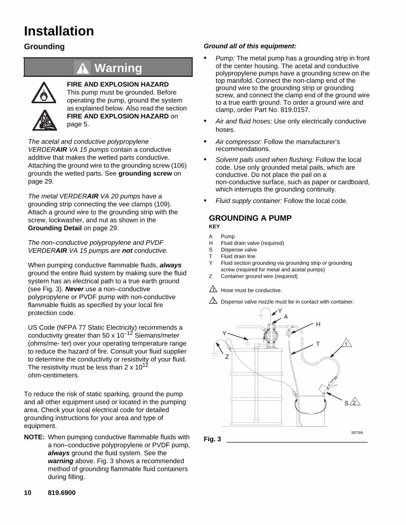
To reduce the risk of static sparking, ground the pump and all other equipment used or located in the pumping area. Check your local electrical code for detailed grounding instructions for your area and type of equipment.
NOTE: When pumping conductive flammable fluids with a non–conductive polypropylene or PVDF pump, always ground the fluid system. See the warning above. Fig. 3 shows a recommended method of grounding flammable fluid containers during filling.
Ground all of this equipment:
• Pump: The metal pump has a grounding strip in front of the center housing. The acetal and conductive polypropylene pumps have a grounding screw on the top manifold. Connect the non-clamp end of the ground wire to the grounding strip or grounding screw, and connect the clamp end of the ground wire to a true earth ground. To order a ground wire and clamp, order Part No. 819.0157.
• Air and fluid hoses: Use only electrically conductive hoses.
• Air compressor: Follow the manufacturer’s recommendations.
• Solvent pails used when flushing: Follow the local code. Use only grounded metal pails, which are conductive. Do not place the pail on a non-conductive surface, such as paper or cardboard, which interrupts the grounding continuity.
• Fluid supply container: Follow the local code.
WarningFIRE AND EXPLOSION HAZARDThis pump must be grounded. Before operating the pump, ground the system as explained below. Also read the section FIRE AND EXPLOSION HAZARD on page 5.
The acetal and conductive polypropylene VERDERAIR VA 15 pumps contain a conductive additive that makes the wetted parts conductive. Attaching the ground wire to the grounding screw (106) grounds the wetted parts. See grounding screw on page 29.
The metal VERDERAIR VA 20 pumps have a grounding strip connecting the vee clamps (109). Attach a ground wire to the grounding strip with the screw, lockwasher, and nut as shown in the Grounding Detail on page 29.
The non–conductive polypropylene and PVDF VERDERAIR VA 15 pumps are not conductive.
When pumping conductive flammable fluids, always ground the entire fluid system by making sure the fluid system has an electrical path to a true earth ground (see Fig. 3). Never use a non–conductive polypropylene or PVDF pump with non-conductive flammable fluids as specified by your local fire protection code.
US Code (NFPA 77 Static Electricity) recommends a conductivity greater than 50 x 10–12 Siemans/meter (ohms/me- ter) over your operating temperature range to reduce the hazard of fire. Consult your fluid supplier to determine the conductivity or resistivity of your fluid. The resistivity must be less than 2 x 10¹² ohm-centimeters.
Fig. 3 ____________________________________________________9079A
AH
S
T
Z
2
1
Y
Y
GROUNDING A PUMPKEY
A PumpH Fluid drain valve (required)S Dispense valveT Fluid drain lineY Fluid section grounding via grounding strip or grounding
screw (required for metal and acetal pumps)Z Container ground wire (required)
Hose must be conductive.
Dispense valve nozzle must be in contact with container.
1
2

819.6900 11
InstallationChanging the Orientation of the Fluid Inlet and Outlet Ports (VERDERAIR VA 15)
You can change the orientation of the fluid inlet and outlet ports by repositioning the manifolds. For VERDERAIR VA 15, see Fig. 4 or Fig. 5. For VERDERAIR VA 20, see Fig. 6.
1. Remove the four manifold nuts (109) or bolts (105).
2. Turn the manifold to the desired position, reinstall the nuts or bolts, and torque to 80 to 90 in-lb (9 to 10 N•m). See Torque Sequence on page 32.
NOTE: Make sure all manifold o-rings are positioned correctly before you fasten the manifold. Manifold o-rings (139) are shown in Fig. 8, Fig. 9, and Fig. 10.
NOTE: Pumps with duckbill check valves are shipped with the inlet manifold on top and the outlet manifold on the bottom. See page 16 for details.
Fig. 4 ______________________________________________________
1109
9065A
1 109
Torque to 80 to 90 in-lb (9 to 10 N•m). See Torque Sequence on page 32.
1
outlet
inlet
Fig. 5______________________________________________________
Fig. 6______________________________________________________
1109
ti22128a
1109
Torque to 80 to 90 in-lb (9 to 10 N•m). See Torque Sequence on page 32.
1
outlet
inlet
inlet
outlet
1 105
9071A
1 105
Torque to 80 to 90 in-lb (9 to 10 N•m). See Torque Sequence on page 32.
1
outlet
inlet

12 819.6900
OperationPressure Relief Procedure
1. Shut off the air to the pump.
2. Open the dispensing valve, if used.
3. Open the fluid drain valve to relieve all fluid pressure, and have a container ready to catch the drainage.
Flush the Pump Before First Use
The pump was tested with water. Prior to first use, flush the pump thoroughly with a compatible solvent. Follow the steps under Starting and Adjusting the Pump.
Starting and Adjusting the Pump
4. Check all fittings to be sure they are tight. Use a compatible liquid thread sealant on all male threads. Tighten the fluid inlet and outlet fittings snugly. Do not over–tighten the fittings into the pump.
5. Place the suction tube (if used) in the fluid to be pumped.
NOTE: If the inlet fluid pressure to the pump is more than 25% of the outlet working pressure, the ball check valves will not close fast enough, resulting in inefficient pump operation.
6. Place the end of the fluid hose (K) into an appropriate container.
7. Close the fluid drain valve (H).
8. With the pump air regulator (G) closed, open all bleedtype master air valves (B, E).
9. If the fluid hose has a dispensing device, hold it open while continuing with the following step. Slowly open the air regulator (G) until the pump starts to cycle. Allow the pump to cycle slowly until all air is pushed out of the lines and the pump is primed.
If you are flushing, run the pump long enough to thoroughly clean the pump and hoses. Close the air regulator. Remove the suction tube from the solvent and place it in the fluid to be pumped.
Operation of Remote Piloted Pumps
1. Follow steps 1–8 above.
2. Open the air regulator (G).
3. The pump will operate when air pressure is alternately applied to the push type connectors (16).
NOTE: Leaving air pressure applied to the air motor for extended periods when the pump is not running may shorten the diaphragm life. Using a 3–way solenoid valve to automatically relieve the pressure on the air motor when the metering cycle is complete prevents this from occurring.
Pump Shutdown
WarningPRESSURIZED EQUIPMENT HAZARDThe equipment stays pressurized until pressure is manually relieved. To reduce the risk of serious injury from pressurized fluid, accidental spray, or splashing fluid, follow this procedure whenever you:
• Are instructed to relieve pressure;
• Stop pumping;
• Check, clean or service any system equipment;
• Install or clean fluid nozzles.
1.Read Toxic Fluid Hazard on page 5.
2.If lifting the pump, follow the Pressure Relief Procedure above.
3.
Be sure the pump is properly grounded.Read Fire and Explosion Hazard on page 5.
WarningThe pump may cycle once before the external signal is applied.
At the end of the work shift, relieve the pressure as described in Pressure Relief Procedure at left.

819.6900 13
MaintenanceLubrication
The air valve is lubricated at the factory to operate without additional lubrication. If you want to provide additional lubrication, remove the hose from the pump air inlet and add two drops of machine oil to the air inlet every 500 hours of operation or every month.
Flushing and Storage
Flush the pump to prevent the fluid you are pumping from drying or freezing in the pump and damaging it. Use a compatible solvent.
Always flush the pump and relieve the pressure before you store it for any length of time.
Tightening Threaded Connections
Before each use, check all hoses for wear or damage and replace as necessary. Check to be sure all threaded connections are tight and leak-free.
Check fasteners. Tighten or retorque as necessary. Although pump use varies, a general guideline is to retorque fasteners every two months. See Torque Sequence on page 32.
Preventive Maintenance Schedule
Establish a preventive maintenance schedule, based on the pump’s service history. This is especially important for prevention of spills or leakage due to diaphragm failure.
CautionDo not over-lubricate the pump. Oil is exhausted through the muffler, which could contaminate your fluid supply or other equipment. Excessive lubrication can also cause the pump to malfunction.
Read Pressure Relief Procedure on page 12.

14 819.6900
Troubleshooting
Read Pressure Relief Procedure on page 12, and relieve the pressure before you check or service the equipment. Check all possible problems and causes before disassembling the pump.
PROBLEM CAUSE SOLUTION
Pump will not cycle, or cycles once and stops.
Air valve is stuck or dirty. Use filtered air.
Pump cycles at stall or fails to hold pressure at stall.
Leaky check valves or o-rings. Replace.
Worn check balls or duckbill valves or guides.
Replace.
Check ball wedged in guide. Repair or replace.
Worn diaphragm shaft seals. Replace.
Pump operates erratically. Clogged suction line. Inspect; clear.
Sticky or leaking check valve balls. Clean or replace.
Diaphragm ruptured. Replace.
Air bubbles in fluid. Suction line is loose. Tighten.
Diaphragm ruptured. Replace.
Loose manifolds or damaged manifold o-rings.
Tighten manifold bolts or nuts; replace o-rings.
Loose fluid side diaphragm plates. Tighten.
Fluid in exhaust air. Diaphragm ruptured. Replace.
Loose fluid side diaphragm plates. Tighten.
Worn diaphragm shaft seals. Replace.
Pump exhausts air from clamps (metal pumps).
Loose clamps. Tighten clamp nuts.
Air valve o-ring is damaged. Inspect; replace.
Pump leaks fluid from check valves. Worn or damaged check valve o-rings. Inspect; replace.

819.6900 15
ServiceAir Valve (VERDERAIR VA 15 and VERDERAIR VA 20 Pumps)
NOTE: Air Valve Repair Kit 819.9740 is available. Parts included in the kit are marked with a dagger (†) in Fig. 7 and in the Parts Drawings and Lists. A tube of general purpose grease 819.0184 is supplied in the kit. Service the air valve as follows. See Fig. 7.
2. Remove the cover (10) and the o-ring (4).
3. Remove the carriage plungers (7), carriages (8), carriage pins (9), and valve plate (14) from the center housing (11).
4. Clean all the parts, and inspect them for wear or damage.
NOTE: If you are installing the new Air Valve Repair Kit 819.9740, use all the parts in the kit.
5. Grease the lapped surface of the valve plate (14), and install the valve plate with the lapped surface facing up.
6. Grease the bores of the center housing (11), install the u-cup packings (2) on the carriage plungers (7), and slide the carriage plungers into the carriage plunger bores. See the following important installation notes:
NOTES:
• When you install each u-cup packing (2) on each carriage plunger (7), make sure the lips of the u-cup packing face toward the clip end (the smaller end) of the carriage plunger.
• When you slide the carriage plungers (7) into the bores, slide them in with the clip ends (the smaller ends) facing toward the center of the center housing (11).
7. Grease the carriage pins (9), and slide the carriage pins into the carriage pin bores.
8. Install the carriages (8). Make sure the carriages engage the clip ends of the carriage plungers (7) and carriage pins (9).
9. Grease the o-ring (4), and seat it in the groove around the cover opening of the center housing (11).
10. Screw cover (10) into center housing, and torque cover from 80 to 100 in–lb (9.0 to 13.6 N•m).
1. Relieve the pressure. See Pressure Relief Procedure on page 12.
Fig. 7. _____________________________________________________________________________________________________________________9
142
8
7
98
2
7
4
101
34
4
2
11
2
2
55
9069A
4 6
4 6
NOTE: Center housing (11) is shown separated from the air covers, but it is not necessary to remove the air covers for this service. Leave the center housing and air covers assembled for this service.
† Included in Air Valve Repair Kit 819.9740.
Torque to 80 to 100 in-lb (9.0 to 13.6 N•m).
Apply grease.
Apply grease to lapped face.
Apply grease to bores of center housing (11) before installing.
Seal lips face clip end (the smaller end) of carriage plunger (7).
Install with the clip ends (the smaller ends) facing toward center of center housing (11)
1
2
3
4
5
6

16 819.6900
Service
Ball or Duckbill Check Valves
NOTE: Fluid Section Repair Kit is available. See page 22 to order the correct kit for your pump. General purpose grease 819.0184 and Adhesive 819.9741 are supplied in the kit.
2. Remove the top and bottom manifolds (102, 103).
3. Remove all parts shown with a dagger (†) in Fig. 8, Fig. 9, and Fig. 10.
4. Clean all parts, and replace worn or damaged parts.
5. Reassemble the pump.
NOTE: Torque the manifold nuts (109) or bolts (105) to 80 to 90 in-lb (9 to 10 N•m). See Torque Sequence on page 32.
Inlet and Outlet for Pumps with Duckbill Check Valves
Pumps with duckbill check valves are shipped with the inlet manifold on top and the outlet manifold on the bottom. To make the inlet manifold on the bottom and the outlet manifold on the top, rotate each of the four duckbill assemblies vertically 180° as shown below.
VERDERAIR VA 15
1. Relieve the pressure. See Pressure Relief Procedure on page 12.
202
201
139
9080b
Fig. 8______________________________________________________
103
202
139
202
201
301
139
201
301
202
201
139
109
109 1
1
202
201
139
9067b
102
139
139
Torque to 80 to 90 in-lb (9 to 10 N•m). See Torque Sequence on page 32.
1

819.6900 17
ServiceVERDERAIR VA 15 Split Manifold VERDERAIR VA 20
Fig. 9 ______________________________________________________
ti22129b
103
109 1
202
201
301
139
139
202
201
301
139
139
102
109 1
Torque to 80 to 90 in-lb (9 to 10 N•m). See Torque Sequence on page 32.
1
Fig. 10 ____________________________________________________
139
201
202
139
201
101
202
139
139
201
202
139
301
301
105
105
106
106
107
102
102
1
1
9081b
139
201
202
Torque to 80 to 90 in-lb (9 to 10 N•m). See Torque Sequence on page 32.
1

18 819.6900
Service
Diaphragms (VERDERAIR VA 15)
NOTE: Fluid Section Repair Kit is available. See page 22 to order the correct kit for your pump. General purpose grease 819.0184 and Adhesive 819.9741 are supplied in the kit. Service the diaphragms as follows. See Fig. 11.
Disassembly
2. Remove manifolds (102 and 103) and fluid covers (101).
NOTE: Make sure all the check valve parts stay in place. See Fig. 8 on page 16.
3. Remove one of the fluid-side diaphragm plates (105) (whichever one comes loose first when you use a wrench on the hex of each), and pull the diaphragm shaft out of the center housing (11).
4. Use a wrench on the flats of the diaphragm shaft (15) to remove the other fluid-side diaphragm plate (105) from the diaphragm shaft.
5. Remove the screws (106), remove the left (114) and right (113) air covers, and remove all old gasket (12) material from the ends of the center housing (11) and the surfaces of the air covers.
6. Remove the diaphragm shaft u-cups (16) and pilot pin o-rings (1).
7. Inspect all parts for wear or damage, and replace as necessary.
Reassembly
1. Insert a diaphragm shaft u-cup (16) and a pilot pin o-ring (1) into the bores of the center housing (11).
NOTE: Make sure the lips of the u-cup face out of the center housing.
2. Line up the holes in the gasket (12) with the holes in the end of the center housing (11), and use six screws (106) to fasten an air cover (113 or 114) to the end of the center housing (11). Torque the screws to 35 to 45 in-lb (4.0 to 5.1 N•m).
3. Position the exhaust cover (13) and o-ring (4) on the center housing (11).
4. Repeat steps 1 and 2 for the other end of the center housing and the remaining air cover.
5. Apply medium-strength (blue) Loctite or equivalent to the threads of the fluid-side diaphragm plates (105). Install on one end of the diaphragm shaft (15) the following parts (see proper order in Fig. 11): air-side diaphragm plate (6) diaphragm (401), and fluid-side diaphragm plate (105).
NOTE: The words “AIR SIDE” on the diaphragm (401) and the flat side of the air-side diaphragm plate (6) must face toward the diaphragm shaft (15).
6. Put grease on the diaphragm shaft (15), and carefully (do not damage the shaft u-cups) run the diaphragm shaft (15) through the center housing (11) bore.
7. Repeat step 5 for the other end of the diaphragm shaft (15), and torque the fluid-side diaphragm plates (105) to 80 to 90 in-lb (9 to 10 N•m) at 100 rpm maximum.
8. Install the muffler (3).
9. Make sure all the check valve parts are in place. See Fig. 8 on page 16.
10. Reinstall the fluid covers (101) and manifolds (102 and 103), and torque the fluid cover and manifold nuts (109) to 80 to 90 in-lb (9 to 10 N•m). See Torque Sequence on page 32.
1. Relieve the pressure. See Pressure Relief Procedure on page 12.

819.6900 19
Service
Diaphragms (VERDERAIR VA 15)
Fig. 11. ___________________________________________________________________________________________________________________9066c
6
12
416
109
105 401
102
109
101
15
11
114
106
103
1
12
3
4
5
6
7
7
7
109
4
13
3
Install with lips facing out of center housing (11).
Torque to 35 to 45 in-lb (4.0 to 5.1 N•m).
Apply grease.
The words “AIR SIDE” on diaphragm must face toward diaphragm shaft (15).
Flat side of air-side diaphragm plate must face toward diaphragm shaft (15).
Apply medium-strength (blue) Loctite® or equivalent to threads, and torque to 80 to 90 in-lb (9 to 10 N•m) at 100 rpm maximum.
Torque to 80 to 90 in-lb (9 to 10 N•m). See Torque Sequence on page 32.
1
2
3
4
5
6
7
20 819.6900
Service
Diaphragms (VERDERAIR VA 20)
NOTE: Fluid Section Repair Kit is available. See page 22 to order the correct kit for your pump. General purpose grease 819.0184 and Adhesive 819.9741 are supplied in the kit. Service the diaphragms as follows. See Fig. 12.
Disassembly
2. Remove the manifolds (102) and fluid covers (101).
NOTE: Make sure all the check valve parts stay in place. See Fig. 10 on page 17.
3. Remove the grounding strip from the vee clamps (109), and remove the vee clamps.
4. Remove one of the fluid-side diaphragm plates (133) (whichever one comes loose first when you use a wrench on the hex of each), and pull the diaphragm shaft out of the center housing (11).
5. Use a wrench on the flats of the diaphragm shaft (15) to remove the other fluid-side diaphragm plate (133) from the diaphragm shaft.
6. Remove the screws (141) and air covers (136), and remove all old gasket (12) material from the ends of the center housing (11) and the surfaces of the air covers.
7. Remove the diaphragm shaft u-cups (16) and pilot pin o-rings (1).
8. Inspect all parts for wear or damage, and replace as necessary.
Reassembly
1. Insert a diaphragm shaft u-cup (16) and a pilot pin o-ring (1) into the end of the diaphragm shaft bore of the center housing (11).
NOTE: Make sure the lips of the u-cup face out of the center housing.
2. Line up the holes in the gasket (12) with the holes in the end of the center housing (11), and use six screws (141) to fasten an air cover (136) to the end of the center housing (11). Torque the screws to 35 to 45 in-lb (4.0 to 5.1 N•m).
3. Position the exhaust cover (13) and o-ring (4) on the center housing (11).
4. Repeat steps 1 and 2 for the other end of the center housing and the remaining air cover.
5. Apply medium-strength (blue) Loctite or equivalent to the threads of the screws (140). Install on one end of the diaphragm shaft (15) the following parts (see proper order in Fig. 12): air-side diaphragm plate (6), diaphragm (401), fluid-side diaphragm plate (133), o-ring (115), and screw (140).
NOTE: The words “AIR SIDE” on the diaphragm (401) and the flat side of the air-side diaphragm plate (6) must face toward the diaphragm shaft (15).
6. Put grease on the diaphragm shaft (15), and carefully (do not damage the shaft u-cups) run the diaphragm shaft (15) through the center housing (11) bore.
7. Repeat step 5 for the other end of the diaphragm shaft (15), and torque the diaphragm shaft screws (140) to 80 to 90 in-lb (9 to 10 N•m) at 100 rpm maximum.
8. Install the muffler (3).
When you install the vee clamps in step 9, orient the center housing (11) so the air inlet is approximately 45° above horzontal and the muffler (3) is approximately horizontal.
9. Apply thin film of grease to inside of vee clamps (109).
10. Position the fluid covers (101), install the vee clamps (109) around the fluid and air covers, install the grounding strip on the vee clamps, and torque the vee clamp nuts to 80 to 90 in–lb (9 to 10 N•m). See Torque Sequence on page 32.
11. Make sure all the check valve parts are in place. See Fig. 10 on page 17.
12. Install the manifolds (102), and torque the manifold bolts (105) to 80 to 90 in-lb (9 to 10 N•m). See Torque Sequence on page 32.
1. Relieve the pressure. See Pressure Relief Procedure on page 12.

819.6900 21
Service
Diaphragms (VERDERAIR VA 20)
Fig. 12. ___________________________________________________________________________________________________________________
11
5
101
102
102
105
105
401
402 6
140
115 416 1
3
109
1412
4
4
6
7
7
136
12
4
3
416 1
9072b
13
133
15
3
Install with lips facing out of center housing (11).
Torque to 35 to 45 in-lb (4.0 to 5.1 N•m).
Apply grease.
The words “AIR SIDE” on diaphragm and backup diaphragm must face toward diaphragm shaft (15).
Flat side of the air-side diaphragm plate must face toward diaphragm shaft (15).
Apply medium-strength (blue) Loctite® or equivalent to threads, and torque to 80 to 90 in-lb (9 to 10 N•m) at 100 rpm maximum.
Torque to 80 to 90 in-lb (9 to 10 N•m). See Torque Sequence on page 32.
1
2
3
4
5
6
7

22 819.6900
VERDERAIR VA 15 and VERDERAIR VA 20 Repair KitsTo order the Air Valve Repair Kit, order Part No. 819.9740.
Ref. No.Pump Model
Fluid Section Material
Check Valve Material Balls Diaphragms Manifold Seals
819.0268 VA20 M/P KY TF SP VT/TF-TF819.0733 VA20 M/P KY VT VT VT/TF-TF819.5053 VA20 M/P AC TF TF VT/TF-TF819.5054 VA20 M/P AC TF HY VT/TF-TF819.5057 VA20 M/P AC TF VT VT/TF-TF819.5059 VA20 M/P AC SS TF VT/TF-TF819.5061 VA20 M/P AC SS SP VT/TF-TF819.5062 VA20 M/P AC SS BN VT/TF-TF819.5066 VA20 M/P AC HY HY VT/TF-TF819.5073 VA20 M/P AC SP SP VT/TF-TF819.5078 VA20 M/P AC BN HY VT/TF-TF819.5080 VA20 M/P AC BN BN VT/TF-TF819.5087 VA20 M/P AC VT VT VT/TF-TF819.5101 VA20 M/P SS TF TF VT/TF-TF819.5102 VA20 M/P SS TF HY VT/TF-TF819.5105 VA20 M/P SS TF VT VT/TF-TF819.5107 VA20 M/P SS SS TF VT/TF-TF819.5108 VA20 M/P SS SS HY VT/TF-TF819.5109 VA20 M/P SS SS SP VT/TF-TF819.5110 VA20 M/P SS SS BN VT/TF-TF819.5111 VA20 M/P SS SS VT VT/TF-TF819.5114 VA20 M/P SS HY HY VT/TF-TF819.5119 VA20 M/P SS SP TF VT/TF-TF819.5121 VA20 M/P SS SP SP VT/TF-TF819.5123 VA20 M/P SS SP VT VT/TF-TF819.5128 VA20 M/P SS BN BN VT/TF-TF819.5129 VA20 M/P SS BN VT VT/TF-TF819.5131 VA20 M/P SS VT TF VT/TF-TF819.5132 VA20 M/P SS VT HY VT/TF-TF819.5135 VA20 M/P SS VT VT VT/TF-TF819.5149 VA20 M/P PP TF TF VT/TF-TF819.5150 VA20 M/P PP TF HY VT/TF-TF819.5151 VA20 M/P PP TF SP VT/TF-TF819.5153 VA20 M/P PP TF VT VT/TF-TF819.5155 VA20 M/P PP SS TF VT/TF-TF819.5157 VA20 M/P PP SS SP VT/TF-TF819.5158 VA20 M/P PP SS BN VT/TF-TF819.5162 VA20 M/P PP HY HY VT/TF-TF819.5167 VA20 M/P PP SP TF VT/TF-TF819.5169 VA20 M/P PP SP SP VT/TF-TF819.5171 VA20 M/P PP SP VT VT/TF-TF819.5176 VA20 M/P PP BN BN VT/TF-TF819.5179 VA20 M/P PP VT TF VT/TF-TF819.5183 VA20 M/P PP VT VT VT/TF-TF
819.6900 23
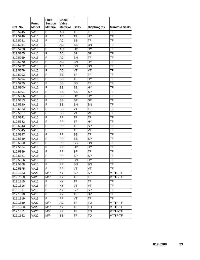
Ref. No.Pump Model
Fluid Section Material
Check Valve Material Balls Diaphragms Manifold Seals
819.5245 VA15 P AC TF TF TF819.5246 VA15 P AC TF HY TF819.5251 VA15 P AC SS TF TF819.5254 VA15 P AC SS BN TF819.5258 VA15 P AC HY HY TF819.5265 VA15 P AC SP SP TF819.5269 VA15 P AC BN TF TF819.5270 VA15 P AC BN HY TF819.5272 VA15 P AC BN BN TF819.5279 VA15 P AC VT VT TF819.5293 VA15 P SS TF TF TF819.5294 VA15 P SS TF HY TF819.5299 VA15 P SS SS TF TF819.5300 VA15 P SS SS HY TF819.5301 VA15 P SS SS SP TF819.5306 VA15 P SS HY HY TF819.5313 VA15 P SS SP SP TF819.5320 VA15 P SS BN BN TF819.5323 VA15 P SS VT TF TF819.5327 VA15 P SS VT VT TF819.5341 VA15 P PP TF TF TF819.5342 VA15 P PP TF HY TF819.5343 VA15 P PP TF SP TF819.5345 VA15 P PP TF VT TF819.5347 VA15 P PP SS TF TF819.5349 VA15 P PP SS SP TF819.5350 VA15 P PP SS BN TF819.5354 VA15 P PP HY HY TF819.5359 VA15 P PP SP TF TF819.5361 VA15 P PP SP SP TF819.5366 VA15 P PP BN HY TF819.5368 VA15 P PP BN BN TF819.5375 VA15 P PP VT VT TF819.1333 VA20 M/P KY SP SP VT/TF-TF819.7050 VA20 M/P KY TF TF VT/TF-TF819.1315 VA15 P KY TF TF TF819.1316 VA15 P KY VT VT TF819.1317 VA15 P KY SP SP TF819.1318 VA15 P KY TF SP TF819.1319 VA15 P PP VT TF TF819.1349 VA20 M/P AC TF TO VT/TF-TF819.1350 VA20 M/P KY TF TO VT/TF-TF819.1351 VA20 M/P PP TF TO VT/TF-TF819.1352 VA20 M/P SS TF TO VT/TF-TF
24 819.6900
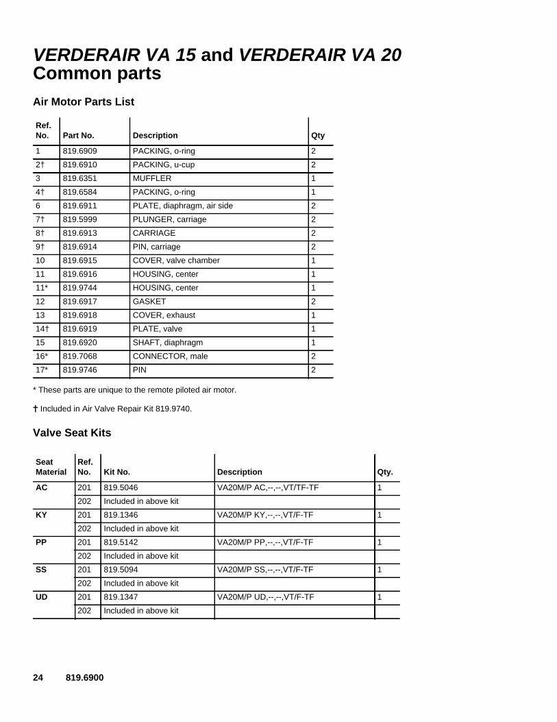
VERDERAIR VA 15 and VERDERAIR VA 20 Common partsAir Motor Parts List
* These parts are unique to the remote piloted air motor.
Included in Air Valve Repair Kit 819.9740.
Valve Seat Kits
Ref. No. Part No. Description Qty
1 819.6909 PACKING, o-ring 2
2† 819.6910 PACKING, u-cup 2
3 819.6351 MUFFLER 1
4† 819.6584 PACKING, o-ring 1
6 819.6911 PLATE, diaphragm, air side 2
7† 819.5999 PLUNGER, carriage 2
8† 819.6913 CARRIAGE 2
9† 819.6914 PIN, carriage 2
10 819.6915 COVER, valve chamber 1
11 819.6916 HOUSING, center 1
11* 819.9744 HOUSING, center 1
12 819.6917 GASKET 2
13 819.6918 COVER, exhaust 1
14† 819.6919 PLATE, valve 1
15 819.6920 SHAFT, diaphragm 1
16* 819.7068 CONNECTOR, male 2
17* 819.9746 PIN 2
Seat Material
Ref. No. Kit No. Description Qty.
AC 201 819.5046 VA20M/P AC,--,--,VT/TF-TF 1
202 Included in above kit
KY 201 819.1346 VA20M/P KY,--,--,VT/F-TF 1
202 Included in above kit
PP 201 819.5142 VA20M/P PP,--,--,VT/F-TF 1
202 Included in above kit
SS 201 819.5094 VA20M/P SS,--,--,VT/F-TF 1
202 Included in above kit
UD 201 819.1347 VA20M/P UD,--,--,VT/F-TF 1
202 Included in above kit

819.6900 25
Check Ball Kits
Diaphragm Kits
Ball Material Ref. No. Kit No. Description Qty.
BN 301 819.5028 VA20M/P --,BN,--,VT/F-TF 1
HY 301 819.5016 VA20M/P --,HY,--,VT/F-TF 1
SP 301 819.5022 / 1
SS 301 819.5010 VA20M/P --,SS,--,VT/F-TF 1
TF 301 819.5004 VA20M/P --,TF,--,VT/F-TF 1
VT 301 819.5034 VA20M/P --,VT,--,VT/F-TF 1
Diaphragm Material
Ref. No. Kit No. Description Qty.
BN401 819.5002 VA20M/P --,--,BN,VT/F-TF 1
416 Included in above kit
HY401 819.5000 VA20M/P --,--,HY,VT/F-TF 1
416 Included in above kit
SP401 819.5001 VA20M/P --,--,SP,VT/F-TF 1
416 Included in above kit
TF 401 819.4999 VA20M/P --,--,TF,VT/F-TF 1
416 Included in above kit
TO 401 819.1348 VA20M/P --,--,TO,VT/F-TF 1
416 Included in above kit
VT401 819.5003 VA20M/P --,--,VT,VT/F-TF 1
416 Included in above kit

26 819.6900
VERDERAIR VA 15 Parts Drawing
202
6
12
9
11
1
4
133
14
4
8
7 2
106
10
15
416
111109
139
202
201
301
139
201
301202
201
139
139
202
201
115
101
104
109
109
9064c
105 401
103
114
106
113
101
117102
17
16
139
139
† Included in Air Valve Repair Kit 819.9740
These parts are unique to the
remote operated air motor.
grounding screw (acetal and conductive polypropylene pumps only)

819.6900 27
VERDERAIR VA 15 Fluid Section Parts ListSee page 24 for Air Motor Parts List
VERDERAIR VA 15 Polypropylene and Conductive Polypropylene Fluid Section Parts List
Ref. No.
Polypropylene Fluid Section (Code 3=P) Conductive Polypropylene Fluid Section (Code 3=C)
Part No. Description Qty Part No. Description Qty
101 819.6945 COVER, fluid; polypropylene 2 819.0260 COVER, fluid; conductive polypropylene 2
102 MANIFOLD, inlet; polypropylene; MANIFOLD, inlet; conductive polypropylene 1
819.6947 BSPT (Code 8=TB) 1 819.0264 BSPT (Code 8=TB)
819.0054 Split inlet; BSPT (Code 8=TB and Code 9=SM) 2 819.0262 NPT (Code 8=TN)
819.9734 NPT (Code 8=TN and Code 9=SM) 2
819.6946 NPT (Code 8=TN) 1
MANIFOLD, Drum Mount (vertical port) (Code 9=OD) 1
819.0775 NPT (Code 8=TN or TB)
103 MANIFOLD, outlet; polypropylene MANIFOLD, outlet; conductive polypropylene; 1
819.6949 BSPT (Code 8=TB) 1 819.0263 BSPT (Code 8=TB)
819.0053 Split outlet; BSPT (Code 8=TB and Code 9=SM) 2 819.0261 NPT (Code 8=TN)
819.9737 NPT (Code 8=TN and Code 9=SM) 2
819.6948 NPT (Code 8=TN) 1
104 819.6951 PLUG; polypropylene; 3/4 BSPT (Code 8=TB) 2 819.6951 PLUG; polypropylene; 3/4 BSPT
(Code 8=TB) 2
819.6950 PLUG; polypropylene; 3/4 npt (Code 8=TN) 2 819.6950
PLUG; polypropylene; 3/4 npt (Code 8=TN)
2
105 819.0202 PLATE, diaphragm, fluid; polypropylene 2 819.0202 PLATE, diaphragm, fluid;
polypropylene 2
106 819.6936 SCREW, machine 12 819.6936 SCREW, machine 13
109 819.6937 NUT, hex, large flange 24 819.6937 NUT, hex, large flange 24
111 819.6313 LABEL, warning 1 819.6313 LABEL, warning 1
113 819.6938 COVER, air, right 1 819.6938 COVER, air, right 1
114 819.6939 COVER, air, left 1 819.6939 COVER, air, left 1
117 819.6953 PLUG; polypropylene; 1/2 BSPT (Code 8=TB) 2 819.6953 PLUG; polypropylene; 1/2 BSPT
(Code 8=TB) 2
819.7157PLUG; polypropylene; 1/2 npt (Code 8=TN)
2 819.7157PLUG; polypropylene; 1/2 npt (Code 8=TN)
2
119 819.6943 RIVET (for plate 116) 2 819.6943 RIVET (for plate 116) 2
139 819.4998 VA20M/P --,--,--,VT/TF-TF 1 819.4998 VA20M/P --,--,--,VT/TF-TF 1

28 819.6900
VERDERAIR VA 15 Fluid Section Parts ListSee page 24 for Air Motor Parts List
VERDERAIR VA 15 Acetal and PVDF Fluid Section Parts List
Ref. No.
Acetal Fluid Section (Code 3=D) PVDF Fluid Section (Code 3=K)
Part No. Description Qty Part No. Description Qty
101 819.6929 COVER, fluid; acetal 2 819.6954 COVER, fluid; PVDF 2
102 819.6931 MANIFOLD, inlet; acetal; BSPT (Code 8=TB) 1 819.6956 MANIFOLD, inlet; PVDF; BSPT
(Code 8=TB) 1
MANIFOLD, Drum Mount, acetal (vertical port) (Code 9=OD)
1819.6955
MANIFOLD, inlet; PVDF; npt(Code 8=TN)
1
819.0776 NPT (Code 8=TN or TB)
103 819.6933 MANIFOLD, outlet; acetal; BSPT (Code 8=TB) 1
819.6958 MANIFOLD, outlet; PVDF; BSPT (Code 8=TB) 1
819.6957MANIFOLD, outlet; PVDF; npt(Code 8=TN)
1
104 819.6935 PLUG; acetal; 3/4 BSPT (Code 8=TB) 2
819.6960 PLUG; PVDF; 3/4 BSPT (Code 8=TB) 2
819.6959 PLUG; PVDF; 3/4 npt (Code 8=TN) 2
105 819.0190 PLATE, diaphragm, fluid; acetal 2 819.6961 PLATE, diaphragm, fluid; PVDF 2
106 819.6936 SCREW, machine 13 819.6936 SCREW, mach. 12
109 819.6937 NUT, hex, large flange 24 819.6937 NUT, hex, large flange 24
111 819.6313 LABEL, warning 1 819.6313 LABEL, warning 1
113 819.6938 COVER, air, right 1 819.6938 COVER, air, right 1
114 819.6939 COVER, air, left 1 819.6939 COVER, air, left 1
117 819.6942 PLUG, acetal; 1/2 BSPT 2819.6963 PLUG; PVDF; 1/2 BSPT (Code
8=TB) 2
819.7153 PLUG; PVDF; 1/2 npt (Code 8=TN) 2
119 819.6943 RIVET (for plate 116) 2 819.6943 RIVET (for plate 116) 2
139 819.4998 VA20M/P --,--,--,VT/TF-TF 1 819.4998 VA20M/P --,--,--,VT/TF-TF 1

819.6900 29
VERDERAIR VA 20 Parts Drawing
139
11
4
13
10
416
139
201
4
15
1
109
101
102
102
202
139
301
108
112
112
401
402
103
104
105
105
106
106
107
6
133
115
121
122
123
9
8 7 2
12
136
110
416
9070b
139
201
202
139
301
140
141
3
14
202
201
139
202
201
17
16
Included in Air Valve Repair Kit 819.9740
These parts are unique to the remote operated air motor.
Grounding Detail

30 819.6900
VERDERAIR VA 20 Fluid Section Parts ListSee page 24 for Air Motor Parts List
VERDERAIR VA 20 Fluid Section Parts List
Ref. No.
Aluminum Fluid Section (Code 3=A) Stainless Steel (sst) Fluid Section (Code 3=S)
Part No. Description Qty Part No. Description Qty
101 819.4457 COVER, fluid; aluminum 2 819.4467 COVER, fluid; sst 2
102
819.6964
MANIFOLD; aluminum 2(1 if
Code 9=OD)
819.6970
MANIFOLD, sst 2(1 if
Code 9=SD)
BSPT (Code 8=TB) BSPT (code 8=TB)
819.4458 NPT (Code 8=TN) 819.4468 NPT (code 8=TN)
MANIFOLD, inlet, Drum Mount (vertical port) (Code 9=OD)
1 MANIFOLD, inlet, Drum Mount (Code 9=SD)
1
819.6999 NPT 819.4468 NPT
103 819.4434 LABEL, warning 1 819.4434 LABEL, warning 1
104 819.6965 LABEL, identification 1 819.6965 LABEL, identification 1
105 819.4459 SCREW; 3/8–16; 2.25 in. (57.2 mm) 8 819.4459 SCREW; 3/8–16; 2.25 in. (57.2 mm) 8
106 819.4460 NUT, hex; 3/8–16; sst 8 819.4460 NUT, hex; 3/8–16; sst 8
107 819.4461 WASHER, flat; 3/8 in.; sst 4 819.4461 WASHER, flat; 3/8 in.; sst 4
108 819.4462 BASE, feet 2 819.4462 BASE, feet 2
109 819.4433 CLAMP, vee 2 819.4433 CLAMP, vee 2
110 819.0198 NUT, clamp; 1/4–28 2 819.0198 NUT, clamp; 1/4–28 2
111 819.6354 STRIP, grounding 1 819.6354 STRIP, grounding 1
112
819.6967
PLUG, steel 2
819.6971
PLUG; sst 2
BSPT (Code 8=TB) BSPT (Code 8=TB)
819.4463 NPT (Code 8=TN) 819.4469 NPT (Code 8=TN)
115 819.6557 O-RING; PTFE 2 819.6557 O-RING; PTFE 2
121 819.6880 SCREW; 10–24; 0.31 in. (8 mm) 1 819.6880 SCREW; 10–24; 0.31 in. (8 mm) 1
122 819.0187 LOCKWASHER; #10 1 819.0187 LOCKWASHER; #10 1
123 819.0185 NUT, hex; 10–24 1 819.0185 NUT, hex; 10–24 1
133 819.6968 PLATE, diaphragm, fluid side; sst 2 819.0356 PLATE, diaphragm, fluid side; sst machined
2
136 819.6969 COVER air 2 819.6969 COVER air 2
139 819.4998 VA20M/P --,--,--,VT/TF-TF 1 819.4998 VA20M/P --,--,--,VT/TF-TF 1
140 819.6556 SCREW, flange; hex head 2 819.6556 SCREW, flange; hex head 2
141 819.6936 SCREW, machine 12 819.6936 SCREW, machine 12
142 819.6943 RIVET (for plate 134) 2 819.6943 RIVET (for plate 134) 2

819.6900 31

32 819.6900
Torque SequenceAlways follow torque sequence when instructed to torque fasteners.
VERDERAIR VA 15
1. Left/Right Fluid CoversTorque bolts to 80–90 in–lb (9–10 N•m).
2. Inlet ManifoldTorque bolts to 80-90 in-lb (9-10 Nm).
3. Outlet ManifoldTorque bolts to 80-90 in-lb (9-10 Nm).
VERDERAIR VA 20
1. Left/Right Fluid CoversTorque bolts to 80–90 in–lb (9–10 N•m).
2. Inlet ManifoldTorque bolts to 80-90 in-lb (9-10 Nm).
3. Outlet ManifoldTorque bolts to 80-90 in-lb (9-10 Nm).
SIDE VIEW
1111
5
7
2
3
88
6
4
11
9
10
12
BOTTOM VIEW
TOP VIEW
13
15
16
14
SIDE VIEW
12
3
4 6
5
4 6
BOTTOM VIEW
TOP VIEW
79
108

819.6900 33
VERDERAIR VA 15 Technical DataMaximum fluid working pressure.................................................................................................................. 100 psi; 0.7 MPa (7 bar)Air pressure operating range........................................................................................ 30 to 100 psi; 0.18 to 0.7 MPa (1.8 to 7 bar)Maximum air consumption ............................................................................................................. 28 scfm; 0.793 cubic meters/min.Maximum free flow delivery..................................................................................................................................... 15 gpm; 57 l/min.Maximum pump speed.......................................................................................................................................................... 400 cpmLiters per cycle ............................................................................................................................................................................. 0.15Maximum suction lift (water) ...................................................................................................................................... 15 ft; 4.5 m dry,
25 ft; 7.6 m wetMaximum size pumpable solids ............................................................................................................................... 3/32 in.; 2.5 mmSound power level (measured per ISO standard 9614–2)
At 70 psig; 0.48 MPa (4.8 bar) at 50 cycles per minute .....................................................................................................77 dBaAt 100 psig; 0.7 MPa (7 bar) at maximum cycles per minute.............................................................................................95 dBa
Sound pressure level (measured 1 meter from pump)At 70 psig; 0.48 MPa (4.8 bar) at 50 cycles per minute ................................................................................................... 67 dBaAt 100 psig; 0.7 MPa (7 bar) at maximum cycles per minute.............................................................................................85 dBa
Air inlet size.......................................................................................................................................................................... 1/4 npt(f)Air exhaust port size..............................................................................................................................................................3/8 npt(f)Fluid inlet size................................................................................................................................................. 1/2 and 3/4 in. bspt(f)Fluid outlet size .............................................................................................................................................. 1/2 and 3/4 in. bspt(f)
Wetted parts (in addition to ball, seat, and diaphragm materials, which vary by pump)Polypropylene pumps.................................................................................................................................. polypropylene, PTFEConductive polypropylene pumps ............................................................................................ groundable polypropylene, PTFEAcetal pumps......................................................................................................................................... groundable acetal, PTFEPVDF pumps ............................................................................................................................................................ PVDF, PTFE
Non-wetted external parts .............................................................. polypropylene, stainless steel, polyester and aluminum (labels), nickel-plated brass
Weight (approximate)Polypropylene pumps............................................................................................................................................... 6.5 lb; 2.9 kgAcetal pumps ........................................................................................................................................................... 7.8 lb; 3.5 kgPVDF pumps ........................................................................................................................................................... 8.5 lb; 3.9 kg
Santoprene® is a registered trademark of the Monsanto Company.
Loctite® is a registered trademark of the Loctite Corporation.
† Reference Code 8, Connections TB=BSP TN=NPT

34 819.6900
VERDERAIR VA 15 DimensionsFRONT VIEW
† Reference Code 8, Connections TB=BSP TN=NPT
35.1 mm
158.8 mm
196.9 mm
109.2 mm
127 mm119 mm
270.0 mm
252.5 mm
217.4 mm
155.4 mm
79.5 mm
109.2 mm
155.4 mm
9077A
202
201
139
SIDE VIEW
* Pumps with duckbill check valves are shipped with the inlet manifold on top and the outlet manifold on the bottom. To make the inlet manifold on the bottom and the outlet manifold on the top, rotate each of the four duckbill assemblies vertically 180° as shown below.
1/4 npt(f)Air Inlet
1/2 bspt(f) Fluid Inlet *†
3/4 bspt(f)Fluid Outlet *†
3/4 bspt(f)Fluid Inlet *†
Four 7.6 mm Diameter Slots
PUMP MOUNTING HOLE PATTERN
1/2 bspt(f) Fluid outlet *†
3/4 (f)†Code 9 = OD

819.6900 35
VERDERAIR VA 20 Technical DataMaximum fluid working pressure...................................................................................................................... 100 psi; 0.7 MPa (7 bar)Air pressure operating range †.......................................................................................... 30 to 100 psi; 0.18 to 0.7 MPa (1.8 to 7 bar)Maximum air consumption ................................................................................................................. 28 scfm; 0.793 cubic meters/min.Maximum free flow delivery......................................................................................................................................... 16 gpm; 61 l/min.Maximum pump speed.............................................................................................................................................................. 400 cpmLiters per cycle ................................................................................................................................................................................. 0.15Maximum suction lift (water) .......................................................................................................................................... 15 ft; 4.5 m dry,
25 ft; 7.6 m wetMaximum size pumpable solids .................................................................................................................................... 3/32 in.; 2.5 mmSound power level (measured per ISO standard 9614–2)
At 70 psig; 0.48 MPa (4.8 bar) at 50 cycles per minute .........................................................................................................77 dBaAt 100 psig; 0.7 MPa (7 bar) at maximum cycles per minute ................................................................................................95 dBa
Sound pressure level (measured 1 meter from pump)At 70 psig; 0.48 MPa (4.8 bar) bar at 50 cycles per minute ..................................................................................................67 dBaAt 100 psig; 0.7 MPa (7 bar) at maximum cycles per minute.................................................................................................85 dBa
Air inlet size...............................................................................................................................................................................1/4 npt(f)Air exhaust port size..................................................................................................................................................................3/8 npt(f)Fluid inlet size .........................................................................................................................................................................3/4 bspt(f)
819.6852, 819.6853, 819.6854, 819.6855, 819.7088, 819.7089, and 819.7090 only.........................................................3/4 npt(f)Fluid outlet size .......................................................................................................................................................................3/4 bspt(f)
819.6852, 819.6853, 819.6854, 819.6855, 819.7088, 819.7089, and 819.7090 only.........................................................3/4 npt(f)Wetted parts (in addition to ball, seat, and diaphragm materials, which vary by pump)
Aluminum pumps ...............................................................................................aluminum, stainless steel, PTFE, zinc-plated steelStainless steel pumps .............................................................................................................................. 316 stainless steel, PTFE
Non-wetted external parts ..........................................................................................polypropylene, stainless steel, polyester (labels), nickel-plated brass, epoxy-coated steel (feet)
Weight (approximate)Aluminum pumps.......................................................................................................................................................... 8.5 lb; 3.9 kgStainless steel pumps ................................................................................................................................................... 18 lb; 8.2 kg
Santoprene® is a registered trademark of the Monsanto Company.
Loctite® is a registered trademark of the Loctite Corporation.
† Startup pressure may vary based on environmental conditions.

36 819.6900
VERDERAIR VA 20 Dimensions
† Reference Code 8, Connections TB=BSP TN=NPT
35.1 mm
153.4 mm
187.2 mm
112.8 mm108.0 mm
264.9 mm
233.2 mm
198.1 mm
168.1 mm
62.5 mm
109.0 mm
109.0 mm
168.1 mm
9078A
202
201
139
SIDE VIEW
* Pumps with duckbill check valves are shipped with the inlet manifold on top and the outlet manifold on the bottom. To make the inlet manifold on the bottom and the outlet manifold on the top, rotate each of the four duckbill assemblies vertically 180 as shown below.
1/4 npt(f) Air Inlet
FRONT VIEW
PUMP MOUNTING HOLE PATTERN
3/4 bspt(f) Fluid Outlet*†
3/4 bspt(f) Fluid Outlet*†
3/4 bspt(f) Fluid Inlets*†3/4 bspt(f)
Fluid Outlets*
3/4 bspt(f) Fluid Inlets*
7.1 mm Diameter Slots
3/4 (f)†Code 9 = OD

819.6900 37
VERDERAIR VA 15 and VA 20 Performance Charts
Fluid Outlet Pressure
Test Conditions: Pump tested in water with inlet submerged.
To find Fluid Outlet Pressure (psi/MPa/bar) at a specific fluid flow (gpm/lpm) and operating air pressure (psi/MPa/bar):1. Locate fluid flow rate along bottom of chart.2. Follow vertical line up to intersection with selected fluid outlet pressure curve.3. Follow left to scale to read fluid outlet pressure.
0
20
40
60
80
100
0 2 4 6 8 10 12 14 16(7.6) (15.2) (22.7) (30.3) (37.9) (45.4) (53.0) (60.6)
(0.7, 7)
(0.55, 5.5)
(0.41, 4.1)
(0.28, 2.8)
(0.14, 1.4)
ABC
A
B
C
FLUID FLOW - gpm (lpm)
FL
UID
OU
TL
ET
PR
ES
SU
RE
- p
si;
MP
a (b
ar)
Fluid Pressure Curvesat 100 psi (0.7 MPa, 7 bar) air pressureat 70 psi (0.48 MPa, 4.8 bar) air pressureat 40 psi (0.28 MPa, 2.8 bar) air pressure

38 819.6900
VERDERAIR VA 15 and VA 20 Performance Charts
Air Consumption
Test Conditions: Pump tested in water with inlet submerged.
To find Pump Air Consumption (scfm or m³/min) at a specific fluid flow (gpm/lpm) and air pressure (psi/MPa/bar):
1. Locate fluid flow rate along bottom of chart.
2. Read vertical line up to intersection with selected air consumption curve.
3. Follow left to scale to read air consumption.
0
5
10
15
20
25
30
0 2 4 6 8 10 12 14 16(7.6) (15.2) (22.7) (30.3) (37.9) (45.4) (53.0) (60.6)
A
B
C
ABC
(0.28)
(0.14)
(0.42)
(0.56)
(0.70)
(0.84)
FLUID FLOW - gpm (lpm)
AIR
CO
NS
UM
PT
ION
– s
cfm
; cu
bic
met
er/m
in
Air Consumption Curvesat 100 psi (0.7 MPa, 7 bar) air pressureat 70 psi (0.48 MPa, 4.8 bar) air pressureat 40 psi (0.28 MPa, 2.8 bar) air pressure

819.6900 39
Customer Services/Guarantee
CUSTOMER SERVICES
If you require spare parts, please contact your local distributor, providing the following details:
• Pump Model
• Type
• Serial Number, and
• Date of First Order.
GUARANTEE
All VERDER pumps are warranted to the original user against defects in workmanship or materials under normal use (rental use excluded) for two years after purchase date. This warranty does not cover failure of parts or components due to normal wear, damage or failure which in the judgement of VERDER arises from misuse.
Parts determined by VERDER to be defective in material or workmanship will be repaired or replaced.
LIMITATION OF LIABILITY
To the extent allowable under applicable law, VERDER’s liability for consequential damages is expressly disclaimed. VERDER’s liability in all events is limited and shall not exceed the purchase price.
WARRANTY DISCLAIMER
VERDER has made an effort to illustrate and describe the products in the enclosed brochure accurately; however, such illustra- tions and descriptions are for the sole purpose of identification and do not express or imply a warranty that the products are merchantable, or fit for a particular purpose, or that the products will necessarily conform to the illustration or descriptions.
PRODUCT SUITABILITY
Many regions, states and localities have codes and regulations governing the sale, construction, installation and/or use of products for certain purposes, which may vary from those in neighboring areas. While VERDER attempts to assure that its products comply with such codes, it cannot guarantee compliance, and cannot be responsible for how the product is installed or used.
Before purchasing and using a product, please review the product application as well as the national and local codes and regulations, and be sure that product, installation, and use complies with them.
Original instructions. This manual contains English.Revision ZAS, January 2020

40 819.6900
é