vhb tad734 2
TRANSCRIPT

Workshop ManualGroup 30
TAD650VE, TAD660VE, TAD734GE, TAD750VE, TAD760VE
I
4(0)


Group 30 Electrical system
Industrial Engines
TAD734GE, TAD650VE, TAD660VE, TAD750VE,TAD760VE
ContentsSafety rules ............................................................ 3
General information .............................................. 4About this Workshop Manual ............................... 4Spare parts .......................................................... 4Certified engines .................................................. 4
Repair instructions................................................ 5Our common responsibility ................................... 6Tightening torques ............................................... 6
Special tools ......................................................... 7
EMS 2 - “Engine Management System” .............. 8General information .............................................. 8CAN - Controller Area Network ............................. 8CIU - Control Interface Unit .................................. 9DCU - Display Control Unit ................................... 9Fuel control ........................................................ 10Calculation of fuel quantity ................................. 10Altitude correction .............................................. 10Diagnostic function ............................................ 10
Component location ........................................... 11TAD 650, 660, 750, 760 VE ............................... 11TAD 734 GE ...................................................... 12
Component description ...................................... 13Starter motor ...................................................... 13Alternator ........................................................... 13Injectors ............................................................. 14Speed sensor, crankshaft .................................. 14Speed sensor, camshaft .................................... 14Sensor, boost pressure/boost temperature .............................................. 15Sensor, oil pressure, engine ............................... 15EGR................................................................... 15Coolant temperature sensor ............................... 16
Sensor, common rail pressure (fuel) ................... 16Sensor, fuel pressure ......................................... 16Magnetically controlled proportional valve(MPROP) ........................................................... 17Water in fuel switch, secondary fuel filter .......... 17Switch, coolant level .......................................... 17Preheater ........................................................... 18Engine control unit, EMS 2 ................................ 18
Repair instructions.............................................. 19General advice on working with EMS engines .... 19Electric welding .................................................. 20Changing the engine control unit ........................ 21Reprogramming a control unit ............................. 22Programming an empty control unit .................... 23Fault tracing of cables and connectors ............... 24Checking the starter motor voltage..................... 26Checking the charging system ........................... 27Rail pressure measurement................................ 28
Malfunctions ........................................................ 29Fault code information ........................................ 29FMI table / SAE standard .................................. 30Manual fault tracing in bus cables ...................... 33
Diagnostic Trouble Codes .................................. 34MID 128, PID 45Inlet air heater status ......................................... 34MID 128, PID 94Fuel pressure ..................................................... 37MID 128, PID 97Water in fuel ....................................................... 43MID 128, PID 100Oil pressure ....................................................... 46MID 128, PID 105Boost temperature ............................................. 52MID 128, PID 106Boost pressure................................................... 58
7747
632
Eng
lish
03–2
007

© 2007 AB VOLVO PENTAWe reserve the right to make modifications without prior notice.
Printed on environmentally compatible paper.
MID 128, PID 108Ambient air pressure .......................................... 64MID 128, PID 110Coolant temperature ........................................... 66MID 128, PID 111Coolant level ...................................................... 72MID 128, PID 158Battery voltage................................................... 76MID 128, PID 164Rail pressure ...................................................... 78MID 128, PID 190Engine speed ..................................................... 84MID 128 / MID 144, PPID 4Start input CIU ................................................... 85MID 128 / MID 144, PPID 6Engine stop switch ............................................. 87MID 128, PPID 19Internal EGR status ........................................... 89MID 128, PPID 55EMS temperature ............................................... 93MID 128, PPID 98Engine sync acknowledge .................................. 95MID 128 / 144, PPID 132Throttle input request failure, DCU/CIU .............. 97MID 128, SID 1-6Injector common rail # 1-6 .................................100MID 128, SID 21Speed sensor camshaft ....................................105MID 128, SID 22Speed sensor, crankshaft .................................110MID 128, SID 39Engine starter relay ...........................................115MID 128, SID 42Injection control pressure regulator ....................118MID 128, SID 70Preheat sense ...................................................122MID 128, SID 2115V sensor supply 2 ...........................................124MID 128, SID 231Communication fault J 1939 ..............................126MID 128, SID 2325V sensor supply 1 ...........................................129MID 128, SID 240Program memory ..............................................131
MID 128, SID 254Controller error ..................................................132MID 128, PSID 96Rail pressure system ........................................133MID 128, PSID 97Rail pressure release valve ...............................137MID 128 / MID 144, PSID 201J1939 communication bus ................................141
Engine protection ..............................................144TAD 650, 660, 750, 760 VE ..............................144TAD 734 GE .....................................................145
Wiring diagrams.................................................146Wiring diagram EMS 2: Vechicle harness TAD 650-760VE ...................146 Engine harness TAD 650-760VE ......................147 Engine harness TAD 734GE ............................148Wiring diagram DCU ..........................................149Wiring diagram CIU ...........................................150
Technicaldata ....................................................151Switch, water in fuel ..........................................151Sensor, fuel pressure ........................................151Speed sensor, camshaft /Speed sensor, crankshaft .................................151Sensor, oil pressure ..........................................151Sensor, rail pressure .........................................151Combination sensor,boost pressure/boost temperature .....................152Sensor, coolant temperature .............................152Switch, coolant level .........................................152Alternator ..........................................................152Starter motor .....................................................152
Index ...................................................................153
References to Service Bulletins ........................153

Group 30: Electrical system Safety information
3
Safety rules
IntroductionThis workshop manual contains technical data, de-scriptions and repair instructions for the Volvo Pentaproducts or product versions noted in the table of con-tents. Check that you have the correct WorkshopManual for your engine.
Read the available safety information, ”General infor-mation” and ”Repair instructions” in this workshopmanual before you start to do any service work.
Never do any work on an engine which justhangs from a lifting device (crane etc.).
The engine must not be run in areas where ex-plosive material or any gases are stored.
Only start the engine in a well-ventilated area. Ifthe engine is run in a confined space, makesure that the crankcase ventilation and exhaustgases can be led away from the workplace.
The battery lockers must never be exposed toopen flames or sparks. Never smoke close tothe batteries. The batteries generate hydrogengas when charged, which can form an explosivegas when mixed with air. This gas mixture isvery flammable and highly explosive. A spark,which can be caused by incorrect battery con-nection, can cause a single spark which is suffi-cient to cause an explosion with resulting dam-age. Do not shift the connections when attempt-ing to start the engine (spark risk) and do notlean over any of the batteries. Please refer tothe advice in the instruction book.
Always ensure that the + (positive pole) and –(negative pole) are securely connected to theirappropriate terminals on the battery. If the bat-teries are wrongly connected, this can causesevere damage to the electrical equipment.Please refer to the wiring diagram.
Always use goggles when charging and han-dling batteries. Battery electrolyte contains sul-furic acid, which is highly corrosive. If batteryacid comes into contact with your skin, wash itoff at once with a lot of soap and water, andthen get medical help. If battery acid comesinto contact with your eyes, flush your eyes atonce (preferably with an eye shower) with a lotof clean water, and then get medical help atonce.
Important!The following special warning symbols occur in thisbook and on the engine.
WARNING! Warns for the risk of personal injury,property damage or that a mechanical fault canoccur if the instructions are not followed.
IMPORTANT! Is used to call attention to thingswhich could cause damage or malfunctions toproduct or property.
NOTE! Is used to call attention to important informa-tion, to facilitate work processes or operation.
Below is a summary of the risks involved and safetyprecautions you should always observe or carry outwhen performing work on the EMS 2 system.
Before electric welding is done, the connectoron the EMS system must be disconnected.Disconnect the engine from system voltage byturning off the main switch.Disconnect the cable connectors from the con-trol unit.Reconnect the EMS 2 control module terminalwhen the electric welding is finished and the elec-tric welding equipment has been disconnected.
Be careful, watch out for the moving compo-nents of the engine during function testing andin operation. Approaching the engine during op-eration entails a risk of personal injury. Remem-ber that loose clothes or long hair can catch onrotating components and cause severe injury.

4
General information
About this Workshop ManualThis workshop manual contains descriptions and re-pair instructions for the standard versions of theTAD734GE, TAD650VE, TAD660VE, TAD750 andTAD760VE engines.
The workshop manual can illustrate tasks done onany of the engines noted above. This means that theillustrations and photographs which clarify certain de-tails might not correspond with other engines in somecases. Repair methods are similar in all important re-spects, however. If this is not the case, this is noted.Important differences are noted separately.
The engine designation and number are noted on thenumber plate and engine decal. The engine designa-tion and number must always be given in all corre-spondence about any product.
The workshop manual is produced primarily for theuse of Volvo Penta workshops and service techni-cians. For this reason the manual presupposes a cer-tain basic knowledge and that the user can carry outthe mechanical/electrical work described to a generalstandard of engineering competence.
Volvo Penta constantly improves its products, so wereserve the right to make modifications without priornotification. All information in this manual is based onproduct data which was available up to the date onwhich the manual was printed. Any material changesintroduced into the product or service methods afterthis date are notified by means of Service Bulletins.
Spare partsSpare parts for electrical and fuel systems are subjectto various national safety requirements. Volvo PentaOriginal Spare Parts meet these specifications. Anykind of damage whatsoever, occasioned by use ofnon-original Volvo Penta spares for the product inquestion, will not be compensated by the warranty of-fered by Volvo Penta.
Certified enginesWhen doing service and repair on emission certi-fied engines, it is important to be aware of the fol-lowing:
Certification means that an engine type has beenchecked and approved by the relevant authority. Theengine manufacturer guarantees that all engines madeof the same type are equivalent to the certified engine.
This makes special demands on service and repairwork, as follows:
● Maintenance and service intervals recommendedby Volvo Penta must be complied with.
● Only Volvo Penta original spares may be used.
● Service to injection pumps, pump settings and in-jectors must always be done by an authorizedVolvo Penta workshop.
● The engine must not be converted or modified,except for the accessories and service kits whichVolvo Penta has approved for the engine.
● No installation changes to the exhaust pipe andengine air inlet ducts may be done.
● No seals may be broken by unauthorized personnel.
The general advice in the instruction book about oper-ation, care and maintenance applies.
IMPORTANT! Delayed or inferior care/mainte-nance, and the use of non-original spares partsmeans that Volvo Penta can no longer be re-sponsible for guaranteeing that the engine com-plies with the certified version.
Damage and/or costs which arise from this willnot be compensated by Volvo Penta.
Group 30: Electrical system General information

Group 30: Electrical system Repair instructions
5
Repair instructions
The working methods described in the workshop man-ual apply to work carried out in a workshop. For thisreason, the engine is lifted out and mounted on an en-gine support. Unless otherwise stated reconditioningwork which can be carried out with the engine in placefollows the same working method.
The warning signs which occur in the workshop manual(please refer to “Safety information” for their meanings).
WARNING!
IMPORTANT!
NOTE!
are not comprehensive in any way, since we can not ofcourse foresee everything, because service work isdone in highly varying circumstances. For this reason,all we can do is to point out the risks which we believecould occur due to incorrect work in a well-equippedworkshop, using work methods and tools tested by us.
All operations described in the Workshop Manual forwhich there are Volvo Penta Special Tools availableassume that these tools are used when carrying outthe repair. Volvo Penta Special Tools have been de-veloped to ensure the most safe and rational workingmethods possible. It is therefore the responsibility ofanyone using other tools or other working methodsthan we recommend to determine that there is no riskof personal injury or mechanical damage or malfunc-tion as a result.
In some cases special safety precautions and user in-structions may be required in order to use the tools andchemicals mentioned in the Workshop Manual. Theserules must always be observed, so there are no specialinstructions about this in the workshop manual.
By following these basic recommendations and usingcommon sense it is possible to avoid most of therisks involved in the work. A clean work place and aclean engine will eliminate many risks of personalinjury and engine malfunction.
Above all, when work on fuel systems, lubricationsystems, inlet systems, turbocharger, bearing capsand seals is done, it is extremely important that nodirt or other kinds of foreign particles are able to getin, since this would otherwise cause malfunctions orshortened repair life.

Repair instructions Group 30: Electrical system
6
Our common responsibilityEach engine consists of a large number of collaborat-ing systems and components. Any deviation of a com-ponent from its technical specification can dramatical-ly increase the environmental impact of an otherwisegood engine. For this reason, it is important that thespecified wear tolerances are observed, that systemswhich are adjustable are correctly adjusted and thatVolvo Penta Original Spares are used for the engine.The stated service intervals in the MaintenanceSchedule (see the Owner’s Manual) must be ob-served.
Some systems, such as the components in the fuelsystem, require special expertise and special testingequipment for service and maintenance. For environ-mental reasons etc., some components are sealed atthe factory. It is only permissible to work on sealedcomponents if you are authorized to do such work.
Remember that most chemical products, incorrectlyused, damage the environment. Volvo Penta recom-mends the use of biodegradable degreasers wheneverengine components are de-greased, unless otherwisespecified in the workshop manual. When workingaboard a boat, be careful to ensure that oils, washresidue etc. are processed for destruction, and are notinadvertently discharged with bilge water into the envi-ronment.
Tightening torquesThe tightening torque for vital fasteners, which shouldbe tightened with a torque wrench, are listed in “Tech-nical Data: Special tightening torques” and noted in thejob descriptions in the book. All torque specificationsapply to clean screws, screw heads and mating faces.Torque data stated apply to lightly oiled or dry threads.If lubricants, locking fluids or sealants are needed on afastener, the type of preparation to be used will be not-ed in the job description and in “Tightening Torques”.For fasteners where specific torque values are not giv-en, please refer to “Technical data: General tighteningtorques”. General torque specifications are target val-ues and the fastener does not need to be tightened witha torque wrench.
Dimension TorqueNm
M5 ................................................. 6
M6 ................................................. 10
M8 ................................................. 25
M10 ............................................... 50
M12 ............................................... 80
M14 ............................................... 140
M16 ............................................... 220

7
Special tools
3838619 VODIA complete diagnostic tool.*Components:
3838620 VODIA – palmtop computer (PDA) with SD card.
3838621 VODIA – docking station. Used with VODIA PDA(3838620).
3838622 VODIA – cable with connector. Used with dock-ing station (3838621) on the engine’s communi-cation connector.
*Note. More detailed information about using the VODIA tool canbe found in the tool’s instruction manual.
885675 Adapter cable for sensor test
9812519 Multimeter
9999324 Terminal crimping tool
9998482 Gauge for connector on control unit
9998699 Measurebox
88890016 Adapter cable
8856753838619
3838620 3838621 3838622
9812519
Special tools Group 30: Electrical system
8889001699986999999324 9998482

EMS 2 - “Engine Management System” Group 30: Electrical system
8
EMS 2 - “Engine Management System”
General informationEMS 2 is an electronic system with CAN communication (Controller Area Network) for diesel engine control. Thesystem has been developed by Volvo and includes fuel control and diagnostic function.
The system consists of a control module, six injectors, a number of sensors that supply the control module withmeasurements, sockets for diagnosis and functional checks. The engine can be connected to a communicationsinterface consisting of a CAN link and a serial link.
CAN - Controller Area NetworkThe J1939 CAN link is responsible after all communi-cation between the engine control unit (EMS 2) and acommunication interface (such as CIU/DCU), exceptfor diagnostics. Diagnostics are managed by the so-called J1708/J1587 link. The CAN link is much fasterthan the J1708/J1587 link and has been designed toconnect to other components that support the SAEJ1939 protocol, such as instrument panels and trans-missions.
If a fault develops on the CAN link, signals for the en-gine speed potentiometer, and the start and stopknobs are taken over by the J1708/J1587 link. Howev-er, instrument and indicator lamps are completelyturned off.
If faults occur in both links, the engine starts to idle.The only way to shut off the engine in this case is touse the auxiliary stop (AUX-STOP).

Group 30: Electrical system EMS 2 - “Engine Management System”
9
DCU - Display Control UnitDCU is a digital instrument panel that communicateswith the engine control module via the CAN link. DCUhas several functions, such as:
Engine control
– Start, stop, speed control, preheating etc.
Monitoring
– Engine speed, boost pressure, boost temperature,coolant temperature, oil pressure, oil temperature,engine hours, battery voltage, instantaneous fuelconsumption and fuel consumption (trip fuel).
Diagnostics
– Shows fault codes in text. Lists previous faults.
Parameter setting
– Idling speed, alarm limit for oil temperature/cool-ant temperature, droop.
– Preheating for ignition.
Information
– Information about hardware, software and engineidentification.
CIU - Control Interface UnitThe CIU is a “translator” between the CAN bus andthe customer’s own control panel. This unit has twoserial communication links, one fast and one slow.
The fast one is a CAN link that features a bus speedof 250 Kbit/s. All data regarding instruments, indicatorlamps, contacts and potentiometers are controlled bythis bus.
The slower J1708/J1587 link handles diagnostic infor-mation for, among other things, the flashing code. TheVODIA diagnosis tool also uses the J1708/J1587 linkto communicate with the system.

EMS 2 - “Engine Management System” Group 30: Electrical system
10
Fuel controlThe amount of fuel injected into the engine and the in-jection advance are fully electronically controlled, viafuel valves in the injectors, once the control unit hasanalyzed the engine’s fuel requirements.
This means that the engine always receives the cor-rect volume of fuel in all operating conditions, whichoffers lower fuel consumption, minimal exhaust emis-sions etc.
The control unit monitors and reads the injectors toensure that the correct volume of fuel is injected intoeach cylinder, and it calculates and set the injectionadvance. Control is mainly done with the help of thespeed sensors, fuel pressure sensor and the com-bined sensor for boost pressure/boost temperature.
The control unit controls the injectors via a signal tothe electromagnetically operated fuel valve in each in-jector, which can be opened and closed.
Calculation of fuel quantityThe quantity of fuel to be injected into the cylinder iscalculated by the control unit. The calculation deter-mines the time that the fuel valve is open (when thefuel valve is open fuel is sprayed into the cylinder).The parameters which govern the amount of fuel in-jected are:
• Demanded engine speed
• Engine protector functions
• Temperature
• Boost pressure
Altitude correctionThe control unit contains an atmospheric pressuresensor and an altitude compensation function for en-gines that operate at high altitude. This function limitsthe fuel volume in relation to ambient air pressure.This is to prevent smoke, high exhaust temperatureand to protect the turbocharger from overspeeding.
Diagnostic functionThe task of the diagnostic function is to discover andlocalize any malfunctions in the EMS 2 system, toprotect the engine and to inform about any problemsthat occur.
If a malfunction is discovered, this is announced bywarning lamps, a flashing diagnostic lamp or in plain lan-guage on the instrument panel, depending on the equip-ment used. If a fault code is obtained as a flashing codeor in plain language, this is used for guidance in any faulttracing. Fault codes can also be read by Volvo’s VODIAtool at authorized Volvo Penta workshops.
In case of serious disturbances, the engine is shutdown completely or the control module decreases thepower output (depending on the application). Onceagain, a fault code is set for guidance in any faulttracing.

Group 30: Electrical system Component location
11
Component location TAD 650, 660, 750, 760 VE
NOTE! Location can differ, depending on engine model.
1. Speed sensor, camshaft
2. Connection, EMS 2
3. Solenoid controlled proportional valve, high pres-sure pump – fuel (MPROP)
4. Fuel pressure
5. Fuel pressure in comman rail
6. Glow plugs, one for each injector
7. Oil pressure sensor
8. Boost pressure and temperature
9. Solenoid valve, EGR
10. Coolant temperature
11. Speed sensor, crankshaft
12. Water in fuel (not shown, mounted on primaryfuel filter).
1
2
3 4 56
7
8
9
10
11

Component description Group 30: Electrical system
12
Component location TAD 734 GE
1. Solenoid controlled proportional valve,high pressure pump – fuel (MPROP)
2. Coolant temperature sensor
3. Water in fuel switch(mounted on primaryfuel filter).
4. Boost pressure and temperature sensor
5. Preheater, intake manifold
6. Fuel pressure in comman rail
7. Fuel pressure sensor
8. Oil pressure sensor
9. Main relay
10. Speed sensor, crankshaft
11. Speed sensor, camshaft

Group 30: Electrical system Component description
13
Starter motorThe starter motor is installed in the flywheel housing,on the left-hand side of the engine. The starter motorrelay is “positive connected”, which means that the re-lay is connected to battery voltage.
AlternatorThe alternator is belt driven and mounted on the frontof the engine, on the right.
Component description

Component description Group 30: Electrical system
14
InjectorsThe injectors are installed on the cylinder head.
The amount of fuel injected and injection duration iscontrolled by the engine control unit, via electromag-netically controlled fuel valves in the injectors. Thismeans that the engine always receives the correctvolume of fuel in all operating conditions, which offerslower fuel consumption, minimal exhaust emissionsetc.
Speed sensor, crankshaftThe engine speed sensor is an inductive sensor.When the crankshaft rotates impulses are created inthe sensor via a tooth wheel on or behind the torsiondamper. The impulses create a pulse signal in thesensor that the engine control unit (EMS 2) uses tocalculate the crankshaft’s rpm.
The tooth wheel has a tooth free gap for the EMS 2 torecognize the crankshafts position.The signal is sent to the engine control unit, whichcalculates the injection in advance and the amount offuel to be injected.
Speed sensor, camshaft (cam-shaft position)The camshaft sensor is an inductive sensor. Whenthe camshaft rotates impulses are created in the sen-sor via a tooth wheel installed on the camshaft. Thetooth has seven teeth, one for each cylinder and oneto determine when cylinder one is to be injected. Theimpulses create a pulse signal in the sensor that theengine control unit (EMS 2) uses to calculate when acylinder is in turn for injection.

Group 30: Electrical system Component description
15
Sensor, boost pressure/ boosttemperatureThe boost pressure and the boost temperature aremeasured by a combined sensor located on the inletmanifold on the left of the engine.
The sensor is supplied by a 5 Volt reference voltagefrom the engine control module.
The boost pressure sensor measures the absolutepressure, which is the sum of the boost pressure andatmospheric pressure (300 kPa thus corresponds to aboost pressure of 200 kPa when atmospheric pres-sure is 100 kPa).
The pressure signal is a voltage signal which is pro-portional to absolute pressure.
The boost temperature sensor consists of a non-lin-ear resistor, whose resistance varies with boost tem-perature. The resistance falls as the temperature ris-es.
Sensor, oil pressure, engineOil pressure is measured by a sensor installed in theengine block on the right side of the engine.
The sensor measures pressure in the main oil gallery,and is supplied by a 5 Volt reference voltage from theengine control module.
The pressure signal is a voltage signal which is pro-portional to the lubrication oil pressure.
IEGR (only VE engines)The IEGR valve is a 2-way solenoid valve controlled bythe engine control unit. The IEGR solenoid controls aoil pressure that effects a control valve which activatethe exhaust gas recirculation function.

Component description Group 30: Electrical system
16
Sensor, fuel pressureThe sensor measures fuel pressure and is located onthe fuel filter bracket. The sensor is an active sensor,i.e. the sensor requires a supply voltage of +5 Volt.The sensor provides an output signal whose voltage isproportional to the pressure that the sensor measures.
Coolant temperature sensorThe sensor is located on the cylinder head, at the rearend of the engine.
The sensor senses the engine coolant temperatureand sends the information to the engine control unit.The sensor consists of a non-linear resistor, whose re-sistance varies with coolant temperature. The resis-tance falls as the coolant temperature rises.
Sensor, common rail pressure(fuel)The sensor is mounted on the right of the engine, atthe front of the common rail, which distributes fuel tothe injectors.
The rail pressure sensor senses the fuel pressure andconverts this to a voltage which is registered by theengine control unit.

Group 30: Electrical system Component description
17
Magnetically controlled propor-tional valve (MPROP)A magnetically controlled proportional valve (MPROP)controls the high pressure pump to ensure that thecorrect fuel pressure (rail pressure) is retained despitevarying engine speed and loading.
The input signal to the valve is a PWM signal whosepulse width is controlled by the engine control module.
When the current through the valve is changed, this af-fects the fuel flow, which results in changed rail pres-sure.
Water in fuel switch, secondaryfuel filterA switch is located in the water trap under the fuel fil-ter. Its task is to detect whether there is water in thefuel.
The switch senses the resistance between two pins,wich are in contact with the fuel. When there is no wa-ter in the fuel, the resistance is very high. If there isany water in the fuel, the resistance falls.
Switch, coolant levelThe task of the switch is to discover whether the cool-ant level in the engine (expansion tank) has becometoo low. An alarm signal is sent when the coolant levelis too low.

Component description Group 30: Electrical system
18
Engine control unit, EMS 2The engine control unit checks and controls the injec-tors, to ensure that the correct volume of fuel is inject-ed into each cylinder at the right time. It also controlsthe high pressure pump via the proportional valve(MPROP) to ensure that the system always has thecorrect fuel pressure (rail pressure).
The control unit also calculates and adjusts the injec-tion advance. Regulation is mainly done with the aid ofthe engine speed sensor and the combined sensor forboost pressure/boost temperature.
The EMS 2 system processor is located in the controlunit, protected from water and vibration.
The processor receives continuous information about:
• Engine speed
• Throttle
• Oil pressure
• Boost pressure /temperature
• Fuel pressure (common rail pressure)
• Fuel alarm, “water in fuel”
• Camshaft position
• Coolant temperature
The information provides information about current op-eration conditions and allows the processor to calculatethe correct fuel volume, monitor engine status etc.
Preheater with preheater relayThe preheater is located in the inlet manifold at the leftside of the engine. The preheat relay is located at theengines left side beneath the preheater.

Group 30: Electrical system Repair instructions
19
General advice on workingwith EMS enginesThe following advice must be followed to avoiddamage to the engine control unit and other elec-tronics.
IMPORTANT! The system must be disconnect-ed from system voltage (by cutting the currentwith the main switch) and the starter key(s) mustbe in the 0 position when the engine controlmodule connectors are disconnected or connect-ed.
● Never disconnect the current with the mainswitches when an engine is running.
● Never undo a battery cable when the engine isrunning.
● Turn the main switches off or disconnect the bat-tery cables during quick charging of the batteries.
● NOTE! During normal trickle charging, it is notnecessary to turn the main switches off.
● Only batteries may be used for start help. A helpstart device can produce a very high voltage anddamage the control unit and other electronics.
● If a connector is disconnected from a sensor, bevery careful to avoid allowing the contact pins tocome into contact with oil, water or dirt.
Repair instructions

Repair instructions Group 30: Electrical system
20
Electric welding1. NOTE! Cut the current with the main switch.
IMPORTANT! The system must be disconnect-ed from system voltage when the engine controlmodule connectors are disconnected or con-nected.
2. Undo the two connectors from the engine controlunit before any electric welding starts. Turn thelocking arm down at the same time as the con-nector is pulled outwards.
3. Disconnect all connections to the alternator.
Connect the welder earth clamp to the componentto be welded, or as close as possible to the weldsite. The clamp must never be connected to theengine or in such a way that current can passthrough a bearing.
IMPORTANT! After welding is completed, thedisconnected components, such as alternatorcables and battery cables must be connected inthe correct order.The battery cables must always be connectedlast.

Group 30: Electrical system Repair instructions
21
Changing the engine controlunit1. NOTE! Cut the current with the main switch.
IMPORTANT! The system must be disconnect-ed from system voltage when the engine controlmodule connectors are disconnected or con-nected*.
2. Remove the two connectors from the engine con-trol unit. Turn the locking arm down at the sametime as the connector is pulled outwards
3. If the new engine control unit has recently beenprogrammed:
Start the engine and check whether any faultcodes related to the engine control unit occur.

Repair instructions Group 30: Electrical system
22
Reprogramming a control unitIMPORTANT! The CHASSIS ID number mustbe readily available to allow the software to bedownloaded.
Action:
1. Log in to Volvo Penta Partner Network’s web-site:
www.vppn.com
2. Choose “VODIA” in the left-hand menu.
3. Choose “ECU programming” in the left-handmenu.
4. Follow the instructions under “Download soft-ware”. Choose the control units to be repro-grammed and click the “Download” button. Thesoftware for the control units is now downloadedto the PDA*.
* Note. PDA = “Personal Digital Assistant” (palmtop computer).
5. Take a look under “Settings”, “Software informa-tion” in VODIA to check that the software hasbeen downloaded.
6. Connect the VODIA to the engine (control unit) tobe programmed.
7. Start with the engine control unit.
Select “Engine with mounting and equipment” inthe VODIA menu.
Select “MID 128 Control unit, programming”.
VODIA will guide you through the entire program-ming process.
8. The next control unit is the vehicle ECU.
Select “Electrical system and instruments” in theVODIA menu.
Select “MID 144 ECU, programming”.
VODIA will guide you through the entire program-ming process.
9. NOTE! Programming must be reported back toVolvo Penta within 28 days. Log in to Volvo Pen-ta Partner Network’s web site:
www.vppn.com
10. Choose “VODIA” in the left-hand menu.
11. Choose “Report software” in the left-hand menu.
12. Follow the instructions for “Report software/pa-rameter”. Click “Report software/parameter”.

Group 30: Electrical system Repair instructions
23
Programming an emptycontrol unitWhen a new engine control unit is installed, where nosoftware has been downloaded, the control unit mustbe programmed.
The new control unit must have the same part numberas the old control unit. If the control units do not havethe same part number, it will not be possible to pro-gram the new control unit until a “Conversion kit” hasbeen ordered from Volvo Penta.
If the control units have the same part number, thenew control unit can be programmed as usual. Pleaserefer to “Programming a control unit”.
If the part numbers do not coincide – proceed as possible:
1. Have both part numbers available.
2. Log in to Volvo Penta Network’s web site:
www.vppn.com
3. Choose “VODIA” in the left-hand menu.
4. Choose “Conversion kit” in the left-hand menu. Anew page, “Conversion kit / Accessory kit”, opensup.
5. Click the text “Available conversions kits” whichis shown in bold face.
6. A new window opens. Follow the instructions giv-en in the window.
7. Return to the “Conversion kit / Accessory kit”page and follow the instructions to order a new“conversion kit”.
8. Volvo Penta’s database is now updated. It cantake about a minute before a confirmation is sent.
9. Programing of the control unit can now start.Please refer to “Programming a control unit”.

Repair instructions Group 30: Electrical system
24
Fault tracing of cables andconnectorsSpecial tools: 9812519, 9998482
Check all connectors visuallyCheck the following:� Look for oxidation which can impair contact in con-
nectors.
� Check that terminals are undamaged, that they arecorrectly inserted into their connectors, and thatthe cable is correctly terminated in the terminal.
● Check that there is good mechanical contact in theconnector. Use a loose pin to check this.
IMPORTANT! The multi-pin connectors forthe engine control unit must only be checkedwith gauge 9998482.
● Carefully insert gauge 9998482 into the multi-pinconnector. Pull and push the connector in and outa few times and feel whether the terminal socketgrasps the tool. If the terminal socket does notgrasp, or if it feels slack, the connection pinsshould be changed. Please refer to ”Joining electri-cal cables for multi-connector” Check the second-ary locking in the connector.
● If possible, shake the cables and pull the connec-tors during measurement to discover whether thecable harness is damaged.
● Check that the cables are not damaged. Avoidclamping cables in tight bends close to the con-nector.
● Check the function of the secondary locking.
Contact problemsIntermittent contact or temporary recurring faults canbe difficult to fault trace, and are frequently caused byoxidation, vibration or poorly terminated cables.
Wear can also cause faults. For this reason, avoid dis-connecting a connector unless it is necessary.
Other contact problems can be caused by damage topins, sockets and connectors etc.
Shake cables and pull connectors during measure-ment, to find where the cable is damaged.
Contact resistance and oxidationResistance in connectors, cables and junctionsshould be close to 0 Ω. A certain amount of resistancewill occur, however, because of oxidation in connec-tors.
If this resistance is too great, malfunctions occur. Theamount of resistance that can be tolerated before mal-functions occur varies, depending on the load in thecircuit.
Open circuitPossible reasons for faults could be chafed or brokencables, or connectors which have come undone.
Use the wiring schedule to check the cable harnesseswhich are relevant to the function. Start off with themost probable cable harness in the circuit.
Check the following:● Disconnect the relevant connector at each end of
the cable harness.
● Use multimeter 9812519 to measure the resis-tance between the ends of the cable.Nominal value close to 0 Ω.
● If possible, shake the cables and pull the connec-tors during measurement to discover whether thecable harness is damaged.
● Check the next cable harness in the wiring sched-ule if no fault has been found.

Group 30: Electrical system Repair instructions
25
Joining electrical cables forconnectorsSpecial tools: 9808648, 9999324Repair kit: 1078054
1Disconnect the connector from the engine control unitor from the power supply unit, please refer to ”Controlunit, changing”.
Undo the connector, to gain access to the cable lead-ing to the pin which is to be changed.
2Undo the pin catch.
3
Remove the pin with tool no. 9808648.
NOTE! Only remove one pin at a time.
4Cut off the cable and the pin which is to be changed.Join the cable with the new one, using repair kit10.78054. Use cable crimping tool no. 9999324.
5Carefully heat the joint with a hot air gun, to make theinsulation shrink and seal tightly.

Repair instructions Group 30: Electrical system
26
Checking the starter motorvoltageSpecial tools: Multimeter 9812519
GeneralIf battery voltage falls below 24.7 V*, the starter motorwill not be able to crank the engine at normal speed.
A fully charged battery has an open circuit voltage ofabout 25.4 V.
* Note. Measured on the batteries.
Voltage measurement, check1Check that the battery voltage is at least 24.7 V* whenunloaded by using multimeter 9812519 to measurebetween the battery poles.
* Note. Measured on the batteries.
2Turn the main switch on.
3Check that the voltage between terminal B+ on the start-er motor and battery negatives connection point is thesame as the battery voltage.
6Put the pin back in the right place in the connector be-fore removing the next pin, if several pins are to bechanged. Check that the locking tongue locks the pinin the connector.
7Install the cables with insulation and tie wraps in theconnector, in the reverse order to disassembly.
8Install the connector in the reverse order to disassembly.
9Check that the connector and the mating connector onthe engine control unit or power supply unit are cleanand dry.
10Join up the multi-pin connector. Please refer to ”Con-trol unit, changing” for advice on joining up the connec-tor.
11Start the engine and check carefully that no faultcodes occur.

Group 30: Electrical system Repair instructions
27
Checking the charging systemSpecial tools: 9812519
Generally about alternators:The voltage output from an alternator must be limitedto prevent the elecrolyte in the battery to evaporate.The alternator output is regulated (limited) by the volt-age regulator in the alternator. The maximum currentthat the alternator can deliver at regulated voltage out-put depends on the alternator revolution. When the en-gine is started an excitation current is needed to“wake up” the alternator.
NOTE! It is the consumers (batteries included) whichdecides the output current from the alternator.
Measurements1. Engine off.
2. Use multimeter 9812519 to do a voltage measure-ment over the battery. The nominal voltage over afull loaded battery is approx. 25.4V.
3. Engine on. Run at 1500 rpm.
4. Use multimeter 9812519 to do a voltage measure-ment over the battery. The nominal charging volt-age over the battery should be approx. 27.8-28.6V.
Fault tracing charging systemBattery1. Check that all connectors at the battery is correct
assembled.
2. Check the conditions of the cables to the battery.
3. Check the water level in the battery.
4. Check, if possible, the specific gravity of all cells.
when no charge1. Check the alternator belt tension.
2. Check that all connectors at the alternator and atthe battery is correct assembled.
3. Check the conditions of all cables in the chargingsystem.
4. Regulator fault, try another alternator.
when undercharge1. Check the alternator belt tension.
2. Check that all connectors at the alternator and atthe battery is correct assembled.
3. Check the conditions of all cables in the chargingsystem.
4. Regulator fault, try another alternator.
when overcharge1. Probably regulator fault, try another alternator.

Repair instructions Group 30: Electrical system
28
Rail pressure measurement
This measurement is used for measuring the rail pres-sure. For example if the engine doesn’t start this mea-surement can show the rail pressure while the engineis cranking. If it is air in the system the rail pressurecould be too low for the engine control unit to activateinjection.
1. NOTE! Starter key in position 0.
2. Undo the connector from the sensor.
3. Connect adapter cable (885675) between the sen-sor and the engine control unit.
4. Use multimeter (9812519) for voltage measure-ment. Connect the COM from the multimeter tomeasurement point 1. Connect V from the multim-eter to measurement point 2.
5. NOTE! Starter key in position I. The multimetershould now show 0.5 Volt which is equal to 0Mpa(0bar).
6. When cranking the engine, read the voltage valueon the multimeter and look in the table which pres-sure the voltage equals.
NOTE! To activate injection a rail pressure of at least25 MPa (250 bar) is demanded.
Voltage 0.5 0.95 1.0 1.1 1.2 1.3 1.4 1.5 1.6 1.7
MPa 0 20.3 22.5 27.0 31.5 36.0 40.5 45.0 49.5 54.0
Bar 0 203.0 225.0 270.0 315.0 360.0 405.0 450.0 495.0 540.0
Voltage 1.8 1.9 2.0 2.1 2.2 2.3 2.4 2.5 2.6 2.7
MPa 58.5 63.0 67.5 72.0 76.5 81.0 85.5 90.0 94.5 99.0
Bar 585.0 630.0 675.0 720.0 765.0 810.0 855.0 900.0 945.0 990.0
Voltage 2.8 2.9 3.0 3.1 3.2 3.3 3.4 3.5 3.6 3.7
MPa 103.5 108.0 112.5 117.0 121.5 126.0 130.5 135.0 139.5 144.0
Bar 1035.0 1080.0 1125.0 1170.0 1215.0 1260.0 1305.0 1350.0 1395.0 1440.0
Voltage 3.8 3.9 4.0 4.1 4.2 4.3 4.4 4.5
MPa 148.5 153.0 157.5 162.0 166.5 171.0 175.5 180.0
Bar 1485.0 1530.0 1575.0 1620.0 1665.0 1710.0 1755.0 1800.0

Group 30: Electrical system Malfunctions
29
Malfunctions
Fault code information• MID - Message Identification Description:
The MID consists of a number which designatesthe control unit that sent the fault code message.(e.g. the engine control unit).
• PID - Parameter Identification Description:The PID consists of a number that designates aparameter (value) to which the fault code relates(oil pressure, for example).
• PPID - Proprietary PID:The same as the PID, but this is a Volvo-specificparameter.
• SID - Subsystem Identification Description:The SID consists of a number that designates acomponent to which the fault code relates(injector, for example).
• PSID - Proprietary SID:The same as the SID, but this is a Volvo-specificcomponent.
• FMI - Failure Mode Identifier:FMI indicates the type of fault (please refer to theFMI table below).
• SPN - Suspect Parameter Number

Malfunctions Group 30: Electrical system
30
FMI tableSAE standardFMI Display text SAE text
0 “Value too high” Valid data, but above the normal working range
1 “Value too low” Valid data, but below the normal working range
2 “Faulty data” Intermittent or faulty data
3 “Electrical fault” Abnormally high voltage or short circuit to higher voltage
4 “Electrical fault” Abnormally low voltage or short circuit to lower voltage
5 “Electrical fault” Abnormally low current or open circuit
6 “Electrical fault” Abnormally high current or short circuit to battery negative
7 “Mechanical fault” Faulty response from mechanical system
8 “Mechanical or electrical fault” Abnormal frequency
9 “Communication fault” Abnormal updating rate
10 “Mechanical or electrical fault” Abnormally large variations
11 “Unknown fault” Unidentified fault
12 “Component fault” Faulty unit or component
13 “Faulty calibration” Calibration values outside the limits
14 “Unknown fault” Special instructions
15 Data valid but above normal operating range - least severe level
16 Data valid but above normal operating range - moderately severe level
17 Data valid but above normal operating range - least severe level
18 Data valid but above normal operating range - moderately severe level
19 Received network data in error
20 Reserved for SAE assignment
21 Reserved for SAE assignment
22 Reserved for SAE assignment
23 Reserved for SAE assignment
24 Reserved for SAE assignment
25 Reserved for SAE assignment
26 Reserved for SAE assignment
27 Reserved for SAE assignment
28 Reserved for SAE assignment
29 Reserved for SAE assignment
30 Reserved for SAE assignment
31 Condition exist

Group 30: Electrical system Malfunctions
31
Volvo-specific for injectors(MID 128, SID 1–6)
FMI Help
3 Short circuit to battery voltage, injector low voltage side
4 Short circuit to battery negative, injector low voltage or high voltage side
5 Open circuit in injector circuit
7 Mechanical system not responding properly
12 Low injector hold current
General adviceNOTE!
The following must be done before fault trac-ing continues, to avoid changing functionalsensors:
● If there is an active/inactive fault code.
Remove the connector from the sensor. Checkthat there is no oxidation and that the connectorpins are not damaged.
If there is a fault, please refer to the instructionsin chapter “Fault tracing of cables and connec-tors”.
NOTE! Some fault codes become inactive when theengine is stopped. Start the engine to check whetherthe fault code is still inactive with the engine running.
● After an action with the connector
Put the connector* back. Check if the fault codebecomes inactive.Check faults that could be related to that specif-ic sensor.
If the fault remains, measure the cables andsensors to check them, as instructed.
*NOTE! No grease in the connector.

Malfunctions Group 30: Electrical system
32
NetworkThe system has two types of communication buses.
CANA data link (CAN bus) links the nodes to each other.CAN (“Controller Area Network”) is an industrial stan-dard for distributed systems.
The CAN bus consists of a pair of copper conductorswhich are twisted 30 times per meter. The nodes com-municate via the CAN bus and they form a network to-gether, which exchanges information and benefitsfrom each other’s services.
The CAN bus is a serial bus and is the primary controlbus.
J1587The communication bus, J1587, is also used for ac-cessories and for diagnostics.
This is a serial bus in accordance with standard SAEJ1708.

Group 30: Electrical system Malfunctions
33
Manual fault tracing in buscablesSpecial tools:Multimeter ..................................................... 9812519
IMPORTANT! Cut the current with the mainswitch before the cables are disconnected.
Use the multimeter to check the bus cables. The con-ductors in the bus cables should not be in contactwith each other.
Disconnect a bus cable at each end and measure theresistance between the pins to check this. The multi-meter should show infinite resistance between eachpin. If the resistance is less than infinite, there is afault.
Measuring the engine cablesTwo types of measurement are done on the enginecable harness, both resistance measurement and volt-age measurement.
The measurements are done to ensure that no opencircuits or short circuits occur.
If there is an open circuit, the resistance is infinite,and if there is a short circuit, it is close to zero. Theresistance values given in the workshop manual areapproximate, and should be regarded as guidelines.
NOTE!
When resistance measurement is done, the engineshould be stopped and system voltage should becut off with the main switch.
All resistance measurement is done at +20°C(68°F) and with a cold engine.

Diagnostic Trouble Codes Group 30: Electrical system
34
MID 128, PID 45
Inlet air heater status
MID 128: Engine control unit
FMI 3: The voltage exceeds the normal value or isshort circuited to higher voltage.
FMI 4: The voltage is less than the normal value oris short circuited to lower voltage.
FMI 5: The current is less than the normal value oris open circuited.
FMI Fault code explanation
3, 4, 5 Faulty sensor / Faulty sensor circuit
Fault indicationDCU: Engine warning in DCU display.
CIU: Flash code
Flash codeElectrical fault: 5.4
Value fault: None
SymptomFMI 3, 5: Preheat relay never activated. White
smoke for cold start. Start problems incold climate.
FMI 4: Induction air is hot. Preheat relay is im-possible to turn off. Preheat fuse willbreak.
Diagnostic Trouble Codes

Group 30: Electrical system Diagnostic Trouble Codes
35
Circuit description
In cold climate the intake air need too be preheated.This is either done for GE engines by the preheaterwhich is located in the inlet manifoldor or for VE en-gines by the glowplugs that are mounted in the cylin-derhead. The preheat function is activated/deactivatedby the engine control unit via the preheat relay. Whenthe preheat function is activated B25 alter its potentialand the relay activates. B7 is a sense cable whichsenses that the voltage supply to the preheater is cor-rect.
Fault tracing
FMI 3 Abnormally high voltage or shortcircuit to higher voltagePossible reason:• Short circuit to B+ in cable harness between EMS
2 and preheat relay.
Suitable action:1. Check cable harness and connectors between
EMS 2 and preheat relay.
pre-heat relay
FMI 4 Abnormally low voltage or shortcircuit to lower voltagePossible reason:• Short circuit to battery negative in cable harness
between EMS 2 and preheat relay.
Suitable action:1. Check cable harness and connectors between
EMS 2 and preheat relay.

Diagnostic Trouble Codes Group 30: Electrical system
36
FMI 5 Abnormally low current or opencircuitPossible reason:• An open circuit in cable harness between EMS 2
and preheat relay.
Suitable action:1. Check the contact pressure in socket 25 in the
engine connector B.
2. Check cable harness and connectors betweenEMS 2 and preheat relay.
Measurements
NOTE! If any of the measurements shows an abnor-mal value, check the wiring to and from the enginecontrol unit and the preheat relay.
Checking the wiring:1. NOTE! Cut the current with the main switch.
2. Remove connector B from the EMS 2.
3. Connect the B connector to brakeout cable9990014 with measurebox 9998699.
4. Use multimeter 9812519 to do a resistance mea-surement.
Measurement points on box Nominal value
7 (preheat sense) - R ≈ 0 Ω one of the preheat connectors
25 (relay activation) - R ≈ 0 Ω one of the preheat connectors
60 (relay +) - R ≈ 0 Ω one of the preheat connectors

Group 30: Electrical system Diagnostic Trouble Codes
37
Circuit description
The sensor is an active sensor, i.e. the sensor mustreceive operating voltage. Pin B17 on the engine con-trol unit provides pin 1 on the sensor with an operatingvoltage of +5 Volt. Pin 4 on the sensor is connected tobattery negative via pin B18 on the engine control unit.The output signal from the pressure sensor, pin 2 onthe sensor to pin B16 on the EMS 2, is a voltage sig-nal that is proportional to the fuel pressure.
MID 128, PID 94
Fuel pressure
MID 128: Engine control unit
FMI 1: The sensor value is valid but below the nor-mal working range.
FMI 3: The voltage exceeds the normal value or isshort circuited to higher voltage.
FMI 5: The current is less than the normal value oris open circuited.
FMI 7: Mechanical fault. The system responds in-correctly.
FMI Fault code explanation
1 Fuel pressure is too low
3, 5 Faulty sensor / Faulty sensor circuit
7 Fuel pressure is critically low
Fault indicationDCU: Engine warning in DCU display.
CIU: Flash code
Flash codeElectrical fault: 3.6
Value fault: 3.8
SymptomNone
splice
splice fuel pres-sure
engineinterface
Note! Only TAD 650, 660, 750, 760 has an engine interface. OnTAD 734 the wiring to the EMS 2 is the same but without any en-gine interface.

Diagnostic Trouble Codes Group 30: Electrical system
38
Fault tracing
FMI 1 Fuel pressure is too lowConditions for fault code:The fuel pressure alarm depends on the engine revo-lution.
Suitable action:1. Check fuel level.
2. Open all fuel cocks and check that no leakageoccurs.
3. Check drive belt adjustment.
4. Change all fuel filters. (pre- and fine filter)
5. Check that no fuel hose is squeezed or folded.
6. Check function of fuel pressure sensor by controlmeasuring the fuel pressure. (see workshop man-ual)
7. Check fuel feed pump.
8. Change fuel pressure release valve. (see work-shop manual)
FMI 3 Abnormally high voltage or shortcircuit to higher voltageConditions for fault code:
The voltage on pin B16 on the EMS 2 is more than4,75 Volt.
Possible reason:• An open circuit in fuel sensor negative cable.
• Short circuited fuel sensor signal cable to 5V volt-age or to battery voltage.
• Faulty sensor.
Suitable action:1. Check contact pressure in socket 18 in the engine
connector B. Also check contact pressure in con-nector at fuel pressure sensor.
2. Check cable harness and connectors between fuelsensor and EMS 2.
3. Check function of fuel pressure sensor.

Group 30: Electrical system Diagnostic Trouble Codes
39
FMI 5 Abnormally low current or opencircuitConditions for fault code:
The voltage on pin B16 on the EMS 2 is less than0.07 Volt.
Possible reason:• An open circuit in fuel sensor 5V supply cable.
• An open circuit in fuel sensor signal cable.
• Short circuited sensor signal cable to battery neg-ative.
• Faulty sensor.
Suitable action:1. Check contact pressure in socket 16 and 17 in
the engine connector B. Also check contact pres-sure in connector at fuel pressure sensor.
2. Check cable harness and connectors between fuelsensor and EMS 2.
3. Check function of fuel pressure sensor.
FMI 7 Critically low pressureConditions for fault code:The fuel pressure alarm depends on the engine revolu-tion.
Suitable action:1. Check fuel level.
2. Open all fuel cocks and check that no leakage oc-curs.
3. Check drivebelt adjustment.
4. Change all fuel filters. (pre- and fine filter)
5. Chech that no fuel hose is squeezed or folded.
6. Check functionof fuel pressure sensor by controlmeasuring the fuel pressure. (see workshop man-ual)
7. Check fuel feed pump.
8. Change fuel pressure release valve. (see workshopmanual)

Diagnostic Trouble Codes Group 30: Electrical system
40
Measurements
NOTE! If any of the measurements shows an abnor-mal value, check the wiring to and from the engine in-terface.
Supply cable• NOTE! Turn ignition off.
• Disconnect the connector from the sensor
• Connect adapter cable 885675 to the cable har-ness connector to the engine control unit.
• Use multimeter 9812519 for voltage measure-ment.
• Turn ignition on.
Measurement points Nominal value
1– 4 U ≈ 5V
Negative cable:• NOTE! Cut the current with the main switch.
• Disconnect the connector from the sensor
• Connect adapter cable 885675 to the cable har-ness connector to the engine control unit.
• Use multimeter 9812519 to do resistance mea-surement against the engine control unit.
Measurement points Nominal value
4 – Battery negative R ≈ 0 Ω
The point of connec-tion for battery nega-tive on the engine

Group 30: Electrical system Diagnostic Trouble Codes
41
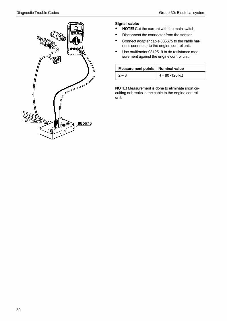
Signal cable:• NOTE! Cut the current with the main switch.
• Disconnect the connector from the sensor
• Connect adapter cable 885675 to the cable har-ness connector to the engine control unit.
• Use multimeter 9812519 to do resistance mea-surement against the engine control unit.
Measurement points Nominal value
4 – 2 R ≈ 80 - 120 kΩ
NOTE! Measurement is done to eliminate short cir-cuiting or breaks in the cable to the engine controlunit.
Diagnostic Trouble Codes Group 30: Electrical system
42
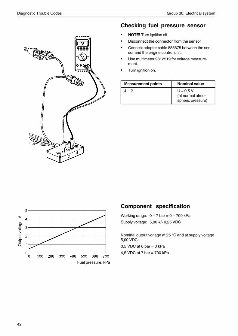
Checking fuel pressure sensor
• NOTE! Turn ignition off.
• Disconnect the connector from the sensor
• Connect adapter cable 885675 between the sen-sor and the engine control unit.
• Use multimeter 9812519 for voltage measure-ment.
• Turn ignition on.
Measurement points Nominal value
4 – 2 U ≈ 0,5 V(at normal atmo-spheric pressure)
Component specification
Working range: 0 – 7 bar = 0 – 700 kPa
Supply voltage: 5,00 +/- 0,25 VDC
Nominal output voltage at 25 °C and at supply voltage5,00 VDC:
0,5 VDC at 0 bar = 0 kPa
4,5 VDC at 7 bar = 700 kPa
Out
put v
olta
ge, V
Fuel pressure, kPa

Group 30: Electrical system Diagnostic Trouble Codes
43
splice
water infuel
MID 128, PID 97
Water in fuel
MID 128: Engine control unit
FMI 0: The sensor value is valid but above the nor-mal working range.
FMI 3: The voltage exceeds the normal value or isshort circuited to higher voltage.
FMI 4: The voltage is less than the normal value oris short circuited to lower voltage.
FMI Fault code explanation
0 Water in fuel
3, 4 Faulty sensor / Faulty monitor circuit
Fault indicationDCU: Engine warning in DCU display
CIU: Flash code
Flash codeElectrical fault: 2.9
Value fault: 2.1
SymptomNone
Circuit description
A monitor is located in the water trap under the fuel fil-ter. Its task is to detect whether there is water in thefuel.
The monitor senses the resistance between two pins,wich are in contact with the fuel. When there is no wa-ter in the fuel, the resistance is very high. If there isany water in the fuel, the resistance falls.
At a threshold resistance (water has been detected),the monitor’s output signal (yellow cable) to the enginecontrol unit pin B8 will be pulled down to zero.
Diagnostic Trouble Codes Group 30: Electrical system
44
Fault tracing
FMI 0 Water in fuelConditions for fault code:
Water in the fuel trap has been detected.
Suitable action:
1. Empty the water trap.
2. Check function of water in fuel monitor.
FMI 3Conditions for fault code:
The voltage signal on B8 is too high.
Possible reason:
• The cable connected to B8 is short circuited tobattery voltage.
Suitable action:
1. Check cable harness and connectors between wa-ter in fuel monitor and EMS 2.
FMI 4Conditions for fault code:
The voltage signal on B8 is too low.
Possible reason:
• Short circuit between both cables to the water infuel monitor.
• The cable connected to B8 is short circuited tobattery negative.
Suitable action:
1. Check cable harness and connectors between wa-ter in fuel monitor and EMS 2.

Group 30: Electrical system Diagnostic Trouble Codes
45
Measurements
Supply cable:
• NOTE! Turn ignition off.
• Disconnect the connector from the monitor
• Use multimeter 9812519 for voltage measurement
• NOTE! Turn ignition on.
Measurement points Nominal value
Yellow conductor – U ≈ Battery voltage x 0.8Black conductor
Negative cable:
• NOTE! Cut the current with the main switch.
• Disconnect the connector from the monitor
• Use multimeter 9812519 to do resistance mea-surement against the engine control unit.
Measurement points Nominal value
Black conductor – R ≈ 0 ΩBattery negative
Checking water in fuel monitor
1. Disconnect the connector to the water in fuel mon-itor.
2. Use multimeter 9812519 to do a resistance mea-surement towards the monitor.
Measurement points Nominal value
1 – 2 Monitor immersed R ≈ 0 Ωin water
1 – 2 Monitor immersed R ≈ ∞ Ωin fuel
Diagnostic Trouble Codes Group 30: Electrical system
46
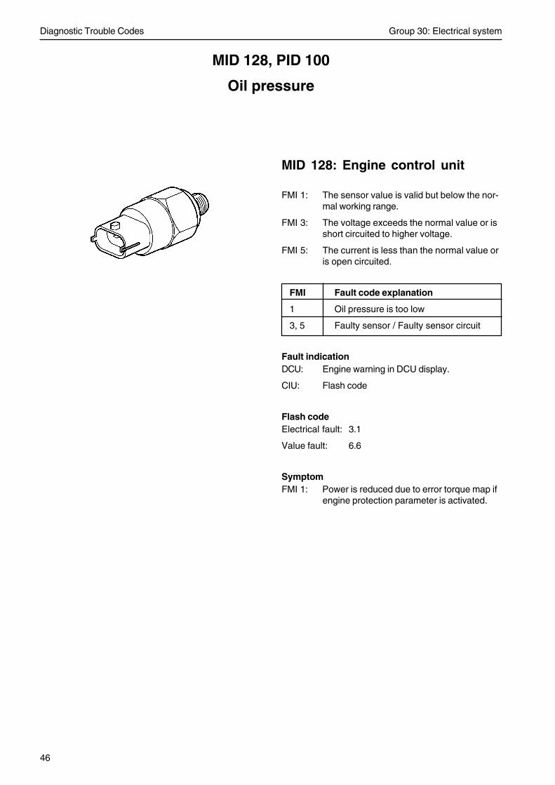
MID 128, PID 100
Oil pressure
MID 128: Engine control unit
FMI 1: The sensor value is valid but below the nor-mal working range.
FMI 3: The voltage exceeds the normal value or isshort circuited to higher voltage.
FMI 5: The current is less than the normal value oris open circuited.
FMI Fault code explanation
1 Oil pressure is too low
3, 5 Faulty sensor / Faulty sensor circuit
Fault indicationDCU: Engine warning in DCU display.
CIU: Flash code
Flash codeElectrical fault: 3.1
Value fault: 6.6
SymptomFMI 1: Power is reduced due to error torque map if
engine protection parameter is activated.

Group 30: Electrical system Diagnostic Trouble Codes
47
Circuit description
The sensor is an active sensor, i.e. the sensor mustreceive operating voltage. Pin B17 on the engine con-trol unit (EMS 2) provides pin 1 on the sensor with anoperating voltage of +5 Volt. Pin 3 on the sensor isconnected to battery negative via pin B18 on the EMS2.
The output signal from the pressure sensor, pin 2 onthe sensor to pin B11 on the EMS 2, is a voltage sig-nal that is proportional to the oil pressure (after the oilfilters).
Fault tracing
FMI 1 Oil pressure is too lowConditions for fault code:
Oil pressure depends on the engine revolution. Oilpressure exceeds the set value of the engine protec-tion parameter.
Possible reason:• Too low engine oil level.
• Blocked oil filter.
• Oil leakage.
• Faulty oil pressure sensor.
Suitable action:1. Check engine oil level and quality of the oil.
2. Change engine oil and oil filter to prevent blockedoil filter.
3. Check that no engine oil leakage occurs.
4. Check function of oil pressure sensor by controlmeasuring the engine oil pressure (see workshopmanual Group 21-26).
oil pressuresplice
splice
Note! Only TAD 650, 660, 750, 760 has an engine interface. OnTAD 734 the wiring to the EMS 2 is the same but without any en-gine interface.

Diagnostic Trouble Codes Group 30: Electrical system
48
FMI 3 Abnormally high voltage or shortcircuit to higher voltageConditions for fault code:
The voltage on pin B11 on the EMS 2 is more than4.95 Volt.
Possible reason:• Short circuit between signal cable and 5V supply
to oil pressure sensor.
• Faulty sensor.
Suitable action:1. Check cable harness and connectors between oil
pressure sensor and EMS 2.
2. Check function of oil pressure sensor.
FMI 5 Abnormally low current or opencircuitConditions for fault code:
The voltage on pin B11 on the EMS 2 is less than 0.07Volt.
Possible reason:• An open circuit in 5V supply cable to oil pressure
sensor.
• An open circuit in signal cable to oil pressure sen-sor.
• Short circuit between signal cable and batterynegative to oil pressure sensor.
• Faulty sensor.
Suitable action:1. Check contact pressure in socket 11 and 17 in
engine connector B. Also check contact pressurein connector at oil pressure sensor.
2. Check cable harness and connectors between oilpressure sensor and EMS 2.
3. Check function of oil pressure sensor.
Group 30: Electrical system Diagnostic Trouble Codes
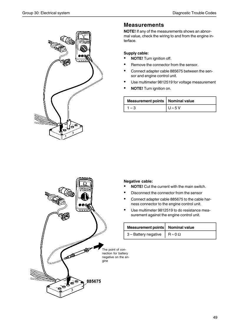
49
MeasurementsNOTE! If any of the measurements shows an abnor-mal value, check the wiring to and from the engine in-terface.
Supply cable:• NOTE! Turn ignition off.
• Remove the connector from the sensor.
• Connect adapter cable 885675 between the sen-sor and engine control unit.
• Use multimeter 9812519 for voltage measurement
• NOTE! Turn ignition on.
Measurement points Nominal value
1 – 3 U ≈ 5 V
Negative cable:• NOTE! Cut the current with the main switch.
• Disconnect the connector from the sensor
• Connect adapter cable 885675 to the cable har-ness connector to the engine control unit.
• Use multimeter 9812519 to do resistance mea-surement against the engine control unit.
Measurement points Nominal value
3 – Battery negative R ≈ 0 Ω
The point of con-nection for batterynegative on the en-gine
Diagnostic Trouble Codes Group 30: Electrical system
50
Signal cable:• NOTE! Cut the current with the main switch.
• Disconnect the connector from the sensor
• Connect adapter cable 885675 to the cable har-ness connector to the engine control unit.
• Use multimeter 9812519 to do resistance mea-surement against the engine control unit.
Measurement points Nominal value
2 – 3 R ≈ 80 -120 kΩ
NOTE! Measurement is done to eliminate short cir-cuiting or breaks in the cable to the engine controlunit.

Group 30: Electrical system Diagnostic Trouble Codes
51
Component specificationWorking range: 0 – 7 bar = 0 – 700 kPa
Supply voltage: 5,00 +/- 0,25 VDC
Nominal output voltage at 25 °C and at supply voltage5,00 VDC:
0,5 VDC at 0 bar = 0 kPa
4,5 VDC at 7 bar = 700 kPa
Checking the oil pressure sensor
• NOTE! Turn ignition off.
• Disconnect the connector from the sensor
• Connect adapter cable 885675 between the sen-sor and the engine control unit.
• Use multimeter 9812519 for voltage measurement
• Turn ignition on.
Measurement points Nominal value
2 – 3 U ≈ 0,5 V (at normalatmospheric pres-sure)
Out
put v
olta
ge, V
Oil pressure, kPa
Diagnostic Trouble Codes Group 30: Electrical system
52
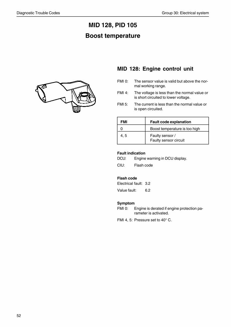
MID 128, PID 105
Boost temperature
MID 128: Engine control unit
FMI 0: The sensor value is valid but above the nor-mal working range.
FMI 4: The voltage is less than the normal value oris short circuited to lower voltage.
FMI 5: The current is less than the normal value oris open circuited.
FMI Fault code explanation
0 Boost temperature is too high
4, 5 Faulty sensor /Faulty sensor circuit
Fault indicationDCU: Engine warning in DCU display.
CIU: Flash code
Flash codeElectrical fault: 3.2
Value fault: 6.2
SymptomFMI 0: Engine is derated if engine protection pa-
rameter is activated.
FMI 4, 5: Pressure set to 40° C.

Group 30: Electrical system Diagnostic Trouble Codes
53
Circuit description
The boost temperature sensor consists of a thermistorwhich forms a closed circuit with an internal resistor inthe engine control unit (EMS 2), via the engine inter-face. The thermistor resistor changes in a non-linearmanner, depending on the boost temperature.
The EMS 2 provides the circuit with a reference volt-age of +5 Volt. The EMS 2 measures the voltage dropover the thermistor via pin A47 and pin A11 on theEMS 2. Pin 1 on the sensor is connected to batterynegative via pin A11 on the EMS 2.
When the boost air is cold, the thermistor resistanceis high and the EMS 2 senses a high voltage drop. Asthe boost air warms up, the resistance in the ther-mistor falls and the voltage drop across it falls.
Fault tracing
FMI 0 Boost temperature is too highConditions for fault code:
Boost temperature exceeds the set value of the en-gine protection parameter.
Possible reason:• Engine temperature is too high.
• High surrounding temperature.
• Dust or dirt on the outside of the intercooler.
• Faulty boost temperature sensor.
Suitable action:1. Check that engine temperature is normal.
2. Clean the intercooler.
3. Check function of boost temperature sensor.
splice
Boost air andtemperaturesplice
engineinterface
Note! Only TAD 650, 660, 750, 760 has an engine interface. OnTAD 734 the wiring to the EMS 2 is the same but without any en-gine interface.

Diagnostic Trouble Codes Group 30: Electrical system
54
FMI 4 Abnormally low voltage or shortcircuit to lower voltageConditions for fault code:
The voltage on pin B47 on the EMS 2 is less than 0.07Volt.
Possible reason:• Short circuited sensor signal cable to battery neg-
ative.
• Faulty sensor.
Suitable action:1. Check cable harness and connectors between
boost temperature sensor and EMS 2.
2. Check function of boost temperature sensor.
FMI 5 Abnormally low current or opencircuitConditions for fault code:
The voltage on pin B47 on the EMS 2 is more than4.95 Volt.
Possible reason:• An open circuit in 5V supply cable to sensor.
• An open circuit in boost temperature signal cable.
• Short circuited sensor signal cable to 5V voltageor to battery voltage.
• Faulty sensor.
Suitable action:1. Check contact pressure in socket 47 and 7 in en-
gine connector A. Also check contact pressure inconnector at boost temperture sensor.
2. Check cable harness and connectors betweenboost temperature sensor and EMS 2.
3. Check function of boost temperature sensor.

Group 30: Electrical system Diagnostic Trouble Codes
55
MeasurementsNOTE! If any of the measurements shows an abnor-mal value, check the wiring to and from the engine in-terface.
Signal cable:• NOTE! Turn ignition off.
• Disconnect the connector from the sensor
• Connect adapter cable 885675 to the cable har-ness connector to the engine control unit.
• Use multimeter 9812519 for voltage measure-ment.
• Turn ignition on.
Measurement points Nominal value
1 – 2 U ≈ 5 V
Negative cable:• NOTE! Cut the current with the main switch.
• Disconnect the connector from the sensor
• Connect adapter cable 885675 to the cable har-ness connector to the engine control unit.
• Use multimeter 9812519 to do resistance mea-surement against the engine control unit.
Measurement points Nominal value
1 – Battery negative R ≈ 0 Ω
The point of con-nection for bat-tery negative onthe engine

Diagnostic Trouble Codes Group 30: Electrical system
56
Checking the sensor cable for open circuit orshort-circuit:• NOTE! Cut the current with the main switch.
• Disconnect the connector from the sensor.
• Connect adapter cable 885675 to the cable har-ness connector to the engine control unit.
• Remove connector A from the engine control unit.
• Use multimeter 9812519 to do a resistance mea-surement against the engine control unit connec-tor A.
Measurement points Nominal value
2 (885675)– 47 (EMS 2, conn.A) R ≈ 0 Ω
2 (885675)– 11(EMS 2, conn.A) R ≈ ∞ Ω
1 (885675)– 47 (EMS 2, conn.A) R ≈ ∞ Ω
1 (885675)– 11(EMS 2, conn.A) R ≈ 0 Ω
NOTE! Measurement is done to eliminate short circuit-ing or breaks in the cable to the engine control unit.
Group 30: Electrical system Diagnostic Trouble Codes
57
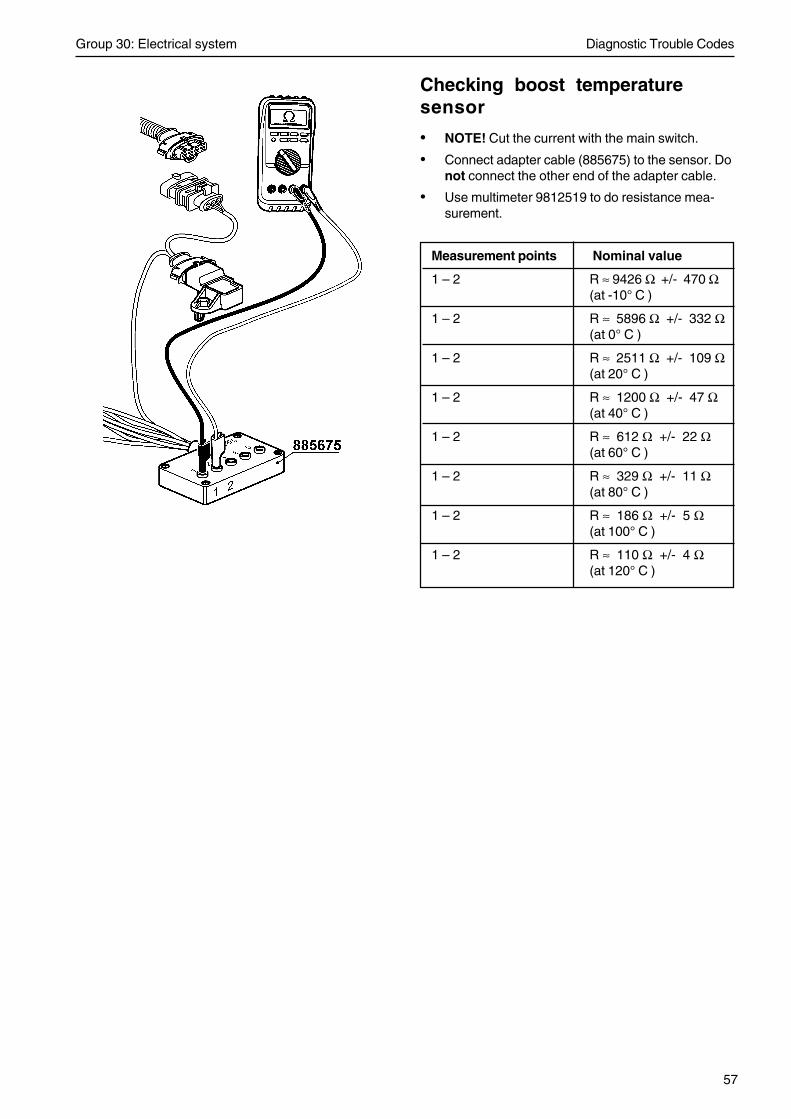
Checking boost temperaturesensor
• NOTE! Cut the current with the main switch.
• Connect adapter cable (885675) to the sensor. Donot connect the other end of the adapter cable.
• Use multimeter 9812519 to do resistance mea-surement.
Measurement points Nominal value
1 – 2 R ≈ 9426 Ω +/- 470 Ω(at -10° C )
1 – 2 R ≈ 5896 Ω +/- 332 Ω(at 0° C )
1 – 2 R ≈ 2511 Ω +/- 109 Ω(at 20° C )
1 – 2 R ≈ 1200 Ω +/- 47 Ω(at 40° C )
1 – 2 R ≈ 612 Ω +/- 22 Ω(at 60° C )
1 – 2 R ≈ 329 Ω +/- 11 Ω(at 80° C )
1 – 2 R ≈ 186 Ω +/- 5 Ω(at 100° C )
1 – 2 R ≈ 110 Ω +/- 4 Ω(at 120° C )

Diagnostic Trouble Codes Group 30: Electrical system
58
MID 128, PID 106
Boost pressure
MID 128: Engine control unit
FMI 0: The sensor value is valid but above the nor-mal working range.
FMI 3: The voltage exceeds the normal value or isshort circuited to higher voltage.
FMI 5: The current is less than the normal value oris open circuited.
FMI Fault code explanation
0 Boost pressure is too high
3, 5 Faulty sensor / Faulty sensor circuit
Fault indicationDCU: Engine warning in DCU display.
CIU: Flash code
Flash codeElectrical fault: 3.4
Value fault: 3.5
SymptomFMI 0: Power is reduced due to error torque map
if engine protection parameter is activat-ed.
FMI 3, 5: Pressure set to atmospheric pressure+ 30 kPa. Engine performance is derated.

Group 30: Electrical system Diagnostic Trouble Codes
59
Circuit description
The sensor is an active sensor, i.e. the sensor mustreceive operating voltage. The boost pressure sensormeasures the absolute pressure, which is the sum ofthe boost pressure and atmospheric pressure (300kPa thus corresponds to a boost pressure of 200 kPawhen atmospheric pressure is 100 kPa).
Pin A7 on the engine control unit (EMS 2) provides pin3 on the sensor with an operating voltage of +5 Volt.Pin 1 on the sensor is connected to battery negativevia pin A11 on the EMS 2. The output signal from thepressure sensor, pin 4 on the sensor to pin A22 on theEMS 2, is a voltage signal that is proportional to theboost pressure.
Fault tracing
FMI 0 Boost pressure is too highConditions for fault code:
Boost pressure exceeds the set value of the engineprotection parameter.
Possible reason:• The wastegate does not function properly.
• Faulty boost pressure sensor.
• Wrong turbo compressor unit according to the en-gine specification.
Suitable action:1. Check wastegate functionality (see workshop
manual Group 21-26).
2. Check function of boost pressure sensor by con-trol measuring boost pressure using a measuringtap (see workshop manual Group 21-26).
3. Check that turbo compressor unit is in accordingto the engine specification.
splice
boost air andtemperaturesplice
engineinterface
Note! Only TAD 650, 660, 750, 760 has an engine interface. OnTAD 734 the wiring to the EMS 2 is the same but without any en-gine interface.

Diagnostic Trouble Codes Group 30: Electrical system
60
FMI 3 Abnormally high voltage or shortcircuit to higher voltageConditions for fault code:
The voltage on pin A22 on the EMS 2 is more than4.75 Volt.
Possible reason:• Short circuited sensor signal cable to 5V voltage
or battery voltage.
• Faulty sensor.
Suitable action:1. Check cable harness and connectors between
boost pressure sensor and EMS 2.
2. Check function of boost pressure sensor.
FMI 5 Abnormally low current or opencircuitConditions for fault code:
The voltage on pin A22 on the EMS 2 is less than 0.07Volt.
Possible reason:• An open circuit in boost pressure signal cable.
• An open circuit in sensor negative cable.
• Short circuited boost pressure signal cable to sen-sor negative cable.
• Faulty sensor.
Suitable action:1. Check contact pressure in socket 22 and 11 in
engine connector A. Also check contact pressurein connector at boost pressure sensor.
2. Check cable harness and connectors betweenboost pressure sensor and EMS 2.
3. Check function of boost pressure sensor.
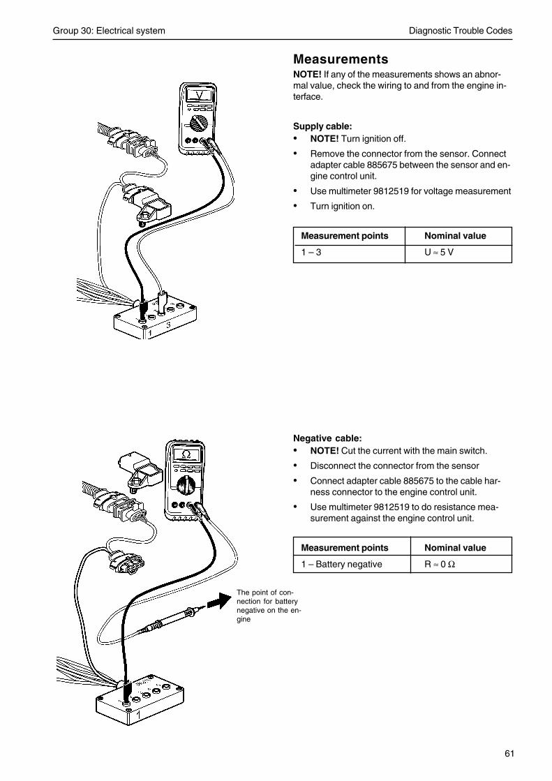
Group 30: Electrical system Diagnostic Trouble Codes
61
MeasurementsNOTE! If any of the measurements shows an abnor-mal value, check the wiring to and from the engine in-terface.
Supply cable:• NOTE! Turn ignition off.
• Remove the connector from the sensor. Connectadapter cable 885675 between the sensor and en-gine control unit.
• Use multimeter 9812519 for voltage measurement
• Turn ignition on.
Measurement points Nominal value
1 – 3 U ≈ 5 V
Negative cable:• NOTE! Cut the current with the main switch.
• Disconnect the connector from the sensor
• Connect adapter cable 885675 to the cable har-ness connector to the engine control unit.
• Use multimeter 9812519 to do resistance mea-surement against the engine control unit.
Measurement points Nominal value
1 – Battery negative R ≈ 0 Ω
The point of con-nection for batterynegative on the en-gine
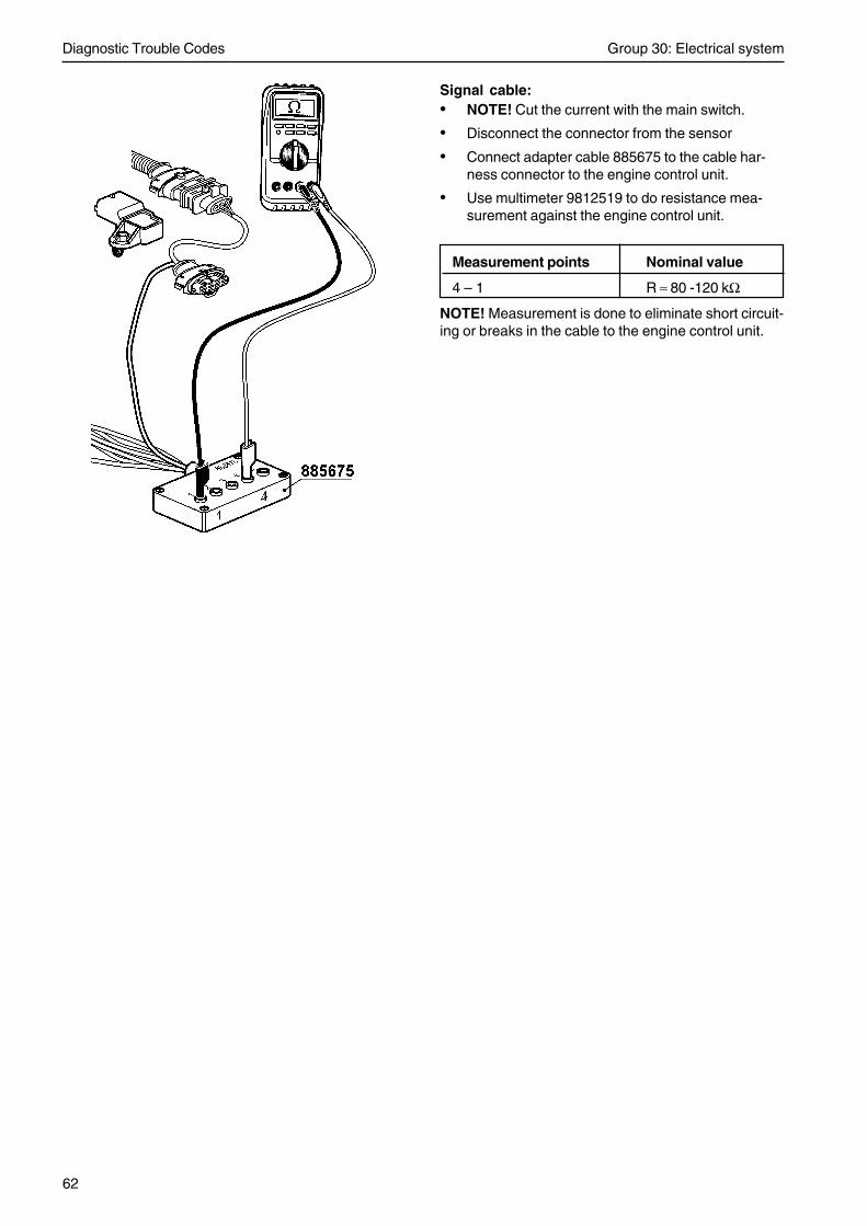
Diagnostic Trouble Codes Group 30: Electrical system
62
Signal cable:• NOTE! Cut the current with the main switch.
• Disconnect the connector from the sensor
• Connect adapter cable 885675 to the cable har-ness connector to the engine control unit.
• Use multimeter 9812519 to do resistance mea-surement against the engine control unit.
Measurement points Nominal value
4 – 1 R ≈ 80 -120 kΩ
NOTE! Measurement is done to eliminate short circuit-ing or breaks in the cable to the engine control unit.

63
Checking boost pressure sensor
• NOTE! Turn ignition off.
• Disconnect the connector from the sensor
• Connect adapter cable 885675 between the sen-sor and the engine control unit.
• Use multimeter 9812519 for voltage measure-ment.
• Turn ignition on.
Measurement points Nominal value
1 – 4 U ≈ 1,1 V (at normalatmospheric pressure)
Component specification
Working range: 0,5 – 4,0 bar = 50 – 400 kPa
Supply voltage: 5,00 +/- 0,25 VDC
Nominal output voltage at 25 °C and at supply voltage5,00 VDC:
0,5 VDC at 0,5 bar = 50 kPa
4,5 VDC at 4 bar = 400 kPa
Out
put v
olta
ge, V
Boost air pressure(absolute pressure), kPa

Diagnostic Trouble Codes Group 30: Electrical system
64
MID 128, PID 108
Ambient air pressure
MID 128: Engine control unit
FMI 2: Intermittent or faulty data.
FMI 3: The voltage exceeds the normal value or isshort circuited to higher voltage.
FMI 4: The voltage is less than the normal value oris short circuited to lower voltage.
FMI Fault code explanation
2 Plausibility
3, 4 Faulty sensor / Faulty sensor circuit
Fault indicationDCU: None
CIU: None
Flash codeElectrical fault: None
Value fault: None
SymptomFMI 3, 4: Ambient pressure is set to 1.0 bar.
Component descriptionSensor is placed inside the engine control unit.

Group 30: Electrical system Diagnostic Trouble Codes
65
Fault tracing
FMI 2, 3, 4Conditions for fault code:
Internal fault in the engine control unit.
Suitable action:1. Replace the engine control unit (EMS 2).

Diagnostic Trouble Codes Group 30: Electrical system
66
MID 128: Engine control unit
FMI 0: The sensor value is valid but abovethe normal working range.
FMI 4: The voltage is less than the normalvalue or is short circuited to lower volt-age.
FMI 5: The current is less than the normal val-ue or is open circuited.
FMI Fault code explanation
0 Coolant temperature too high
4, 5 Faulty sensor / Faulty sensor circuit
Fault indicationDCU: Engine warning in DCU display
CIU: Flash code
Flash codeElectrical fault: 3.3
Value fault: 6.1
SymptomFMI 0: Engine is derated if engine protection
parameter is activated
FMI 4, 5: Engine is difficult to start
MID 128, PID 110
Coolant temperature

Group 30: Electrical system Diagnostic Trouble Codes
67
Circuit description
The coolant temperature sensor consists of a ther-mistor which forms a closed circuit with an internal re-sistor in the engine control unit (EMS 2) via the en-gine interface. The thermistor resistor changes in anon-linear manner, depending on the coolant tempera-ture. The EMS 2 provides the circuit with a referencevoltage of +5 Volt. The EMS 2 measures the voltagedrop over the thermistor via pin B27 and pin B18 onthe EMS 2. Pin 1 on the sensor is connected to bat-tery negative via pin B18 on the EMS 2. When thecoolant is cold, the thermistor resistance is high andthe EMS 2 senses a high voltage drop. As the coolantwarms up, the resistance in the thermistor falls andthe voltage drop across it falls.
Fault tracing
FMI 0: Coolant temperature is too high
Conditions for fault code:
Coolant water temperature exceeds the set value ofthe engine protection.
Possible reason:
• Coolant level too low.
• Dust or dirt on the outside of the radiator.
• Drive belt is not properly adjusted.
• There is air in the coolant water system.
• Faulty thermostat.
• Faulty temperature sensor.
• Clogged cooling water system.
Suitable action:
1. Check coolant level.
2. Check outside of the radiator for dust and dirt.
3. Check drive belt adjustment.
4. Bleed coolant water system.
5. If low coolant level check coolant water system forleakage by a pressure test.
6. Check coolant pressure valve in the coolant cupor try with another coolant cup.
7. Check coolant water thermostat or change cool-ant water thermostat.
8. Check function of coolant temperature sensor.
9. Clean cooling water system.
skall vara 18 ej 10
coolant tem-perture
splice
engineinterface
Note! Only TAD 650, 660, 750, 760 has an engine interface. OnTAD 734 the wiring to the EMS 2 is the same but without any en-gine interface.

Diagnostic Trouble Codes Group 30: Electrical system
68
FMI 4 Abnormally low voltage or shortcircuit to lower voltage
Conditions for fault code:
The voltage on pin B18 on the EMS 2 is less than 0.07Volt.
Possible reason:
• Short circuit between both cables to the coolanttemperature sensor.
• Faulty sensor.
Suitable action:
1. Check cable harness and all connectors betweencoolant temperature sensor and EMS 2.
2. Check function of coolant temperature sensor.
FMI 5 Abnormally low current or opencircuit
Conditions for fault code:
The voltage on pin B27 on the EMS 2 is more than4.95 Volt.
Possible reason:
• Open circuit in signal cable to temperature sen-sor.
• Open circuit in negative cable to temperature sen-sor.
• Faulty sensor.
Suitable action:
1. Check contact pressure in socket 18 and 27 inengine connector B. Check also contact pressurein connector at coolant temperature sensor.
2. Check cable harness and all connectors betweencoolant temperature sensor and EMS 2.
3. Check function of coolant temperature sensor.

Group 30: Electrical system Diagnostic Trouble Codes
69
Measurements
NOTE! If any of the measurements shows an abnor-mal value, check the wiring to and from the engine in-terface.
Signal cable:• NOTE! Turn ignition off.
• Disconnect the connector from the sensor.
• Connect adapter cable 885675 to the cable har-ness connector to the engine control unit.
• Use multimeter 9812519 for voltage measure-ment.
• NOTE! Turn ignition on.
Measurement points Nominal value
1 – 2 U ≈ 5 V
Negative cable:• NOTE! Cut the current with the main switch.
• Disconnect the connector from the sensor
• Connect adapter cable 885675 to the cable har-ness connector to the engine control unit.
• Use multimeter 9812519 to do resistance mea-surement against the engine control unit.
Measurement points Nominal value
1 – Battery negative R ≈ 0 Ω
The point of connection forbattery negative on the en-gine
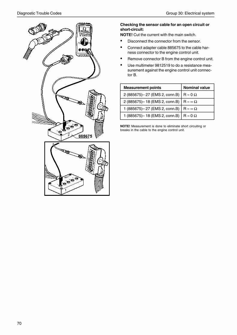
Diagnostic Trouble Codes Group 30: Electrical system
70
Checking the sensor cable for an open circuit orshort-circuit:NOTE! Cut the current with the main switch.
• Disconnect the connector from the sensor.
• Connect adapter cable 885675 to the cable har-ness connector to the engine control unit.
• Remove connector B from the engine control unit.
• Use multimeter 9812519 to do a resistance mea-surement against the engine control unit connec-tor B.
Measurement points Nominal value
2 (885675)– 27 (EMS 2, conn.B) R ≈ 0 Ω
2 (885675)– 18 (EMS 2, conn.B) R ≈ ∞ Ω
1 (885675)– 27 (EMS 2, conn.B) R ≈ ∞ Ω
1 (885675)– 18 (EMS 2, conn.B) R ≈ 0 Ω
NOTE! Measurement is done to eliminate short circuiting orbreaks in the cable to the engine control unit.

Group 30: Electrical system Diagnostic Trouble Codes
71
Checking coolant temperaturesensor
• NOTE! Cut the current with the main switch.
• Connect adapter cable 885675 to the sensor.Do not connect the other end of the adapter ca-ble.
• Use multimeter 9812519 to do resistance mea-surement.
Measurement points Nominal value
1 – 2 R ≈ 9397 Ω+/- 755 Ω (at -10° C )
1 – 2 R ≈ 5896 Ω+/- 430 Ω (at 0° C )
1 – 2 R ≈ 2500 Ω+/- 148 Ω (at 20° C )
1 – 2 R ≈ 1175 Ω+/- 56 Ω (at 40° C )
1 – 2 R ≈ 596 Ω+/- 22 Ω (at 60° C )
1 – 2 R ≈ 323 Ω+/- 10 Ω (at 80° C )
1 – 2 R ≈ 186 Ω+/- 5 Ω (at 100° C )
1 – 2 R ≈ 113 Ω+/- 4 Ω (at 120° C )

Diagnostic Trouble Codes Group 30: Electrical system
72
MID 128, PID 111
Coolant level
MID 128: Engine control unit
FMI 1: The sensor value is valid but below the nor-mal working range.
FMI 3: The voltage exceeds the normal value or isshort circuited to higher voltage.
FMI Fault code explanation
1 Coolant level is too low
3 Faulty sensor / Faulty sensor circuit
Fault indicationDCU: Engine warning in DCU display.
CIU: Flash code
Flash codeElectrical fault: 2.3
Value fault: 2.2
SymptomFMI 1VE engines: Engine is derated if engine protection pa-rameter is activated.
GE engines: Engine is shutdown.

Group 30: Electrical system Diagnostic Trouble Codes
73
Circuit descriptionThe coolant level in the engine is monitored by a levelswitch. Pin B23 on the engine control unit (EMS 2)provides pin 1 on the level switch with a voltage. Pin 2on the level switch is connected to battery negative viapin B10 on the engine control unit.
The level switch has two states: On/Off.
The level switch consists of two sections, the actualswitch and a magnetic float which is built into the ex-pansion tank. The switch senses the position of themagnetic float. When the coolant level falls, the floatoperates the switch and a closed circuit is formed.
Fault tracing
FMI 1 Coolant level is too lowSuitable action:1. Check coolant level.
2. Bleed coolant water system.
3. If low coolant level check coolant water system forleakage by a pressure test.
4. Check pressure valve in the coolant cup or try withanother coolant cup.
5. Check wiring to the coolant level switch.
6. Check function of coolant level switch.
FMI 3 Abnormally high voltage or shortcircuit to higher voltage has beendetected.Fault condition:The voltage on pin B23 in the engine control unit is toohigh.
Possible reason:• Short circuit to battery voltage on pin B23.
Suitable action:1. Check cable harness and connectors between
coolant level monitor and EMS2.
coolant level

Diagnostic Trouble Codes Group 30: Electrical system
74
Measurements
Supply cable:• NOTE! Turn ignition off.
• Disconnect the connector from the level switch.
• Connect adapter cable 885675 to the cable har-ness connector to the engine control unit.
• Use multimeter 9812519 for voltage measurement
• NOTE! Turn the ignition on.
Measurement points Nominal value
1 – 2 U ≈ Battery voltage x 0.8
Negative cable:• NOTE! Cut the current with the main switch.
• Disconnect the connector from the level switch.
• Connect adapter cable 885675 to the cable har-ness connector to the engine control unit.
• Use multimeter 9812519 to do resistance mea-surement against the engine control unit.
Measurement points Nominal value
2 – Battery negative R ≈ 0 Ω
The point of con-nection for batterynegative on the en-gine

Group 30: Electrical system Diagnostic Trouble Codes
75
Checking coolant switch
NOTE! The coolant level monitor can be removedwithout having to drain the coolant.
1. Undo the connector and remove the level switchfrom the expansion tank.
2. Use multimeter 9812519 to do resistance mea-surement against the switch.
Measurement points Nominal value
Blue – Black R ≈ ∞ Ω
3. Move a magnet along the monitor and observe theresistance value. The resistance should drop toapprox. 0 Ohm.
Measurement points Nominal value
Blue – Black R ≈ 0 Ω

Diagnostic Trouble Codes Group 30: Electrical system
76
MID 128, PID 158
Battery voltage
MID 128: Engine control unit
FMI 1: The sensor value is valid but below the nor-mal working range.
FMI Fault code explanation
1 Bellow range
Fault indicationDCU: Engine warning in DCU display.
CIU: Flash code
Flash codeElectrical fault: None (EMS)
Value fault: 3.9 (EMS)
Electrical fault: None (CIU)
Value fault: 6.9 (CIU)
SymptomCould be engine starting problems.

Group 30: Electrical system Diagnostic Trouble Codes
77
Fault tracing
FMI 1 Less than normal working range.Possible reason:Battery voltage less than 24.1V
Possible reason:• Altenator belt
• Flat / poor batteries
• Fault in cables or connectors for battery / alterna-tor
• Faulty altenator
Suitable action:1. Check battery cables and connections.
2. Check / charge batteries.
3. Check altenator and drive belt.

Diagnostic Trouble Codes Group 30: Electrical system
78
MID 128, PID 164
Rail pressure
MID 128: Engine control unit
FMI 0: The sensor value is valid but above the nor-mal working range.
FMI 2: Intermittent or faulty data.
FMI 4: The voltage is less than the normal value oris short circuited to lower voltage.
FMI 5: The current is less than the normal value oris open circuited.
FMI Fault code explanation
0 Sensor out of range
2 Plausibility
4, 5 Faulty sensor / Faulty sensor circuit
Fault indicationDCU: Engine warning in DCU display.
CIU: None
Lamp statusFMI 0: None
FMI 2, 4, 5: Yellow lamp
Flash codeElectrical fault: 8.3
Value fault: None
SymptomFMI 2, 4, 5: Engine speed limitation (1100rpm).
Full fuel flow delivery, limp home withpressure release valve opened. An esti-mated rail pressure with depending tofuel quantity will be used.

Group 30: Electrical system Diagnostic Trouble Codes
79
Circuit description
The sensor is an active sensor, i.e. the sensor mustreceive operating voltage. Pin A7 on the engine controlunit (EMS 2) provides pin 3 on the sensor with an op-erating voltage of +5 Volt. Pin 1 on the sensor is con-nected to battery negative via pin A11 on the EMS 2.The output signal from the pressure sensor, pin 2 onthe sensor to pin A19 on the EMS 2, is a voltage sig-nal that is proportional to the rail pressure.
Fault tracing
FMI 0 Rail pressure is too highConditions for fault code:
Rail pressure depends on engine revolution and en-gine load.
Possible reason:• Faulty MROP.
• Faulty rail pressure sensor.
Suitable action:1. Check MPROP cables and connectors.
2. Check function of rail pressure sensor.
FMI 2Conditions for fault code:
Plausibility fault.
Possible reason:• Faulty rail pressure sensor.
Suitable reason:1. Check function of rail pressure sensor.
rail pressure
engineinterface
Note! Only TAD 650, 660, 750, 760 has an engine interface. OnTAD 734 the wiring to the EMS 2 is the same but without any en-gine interface.

Diagnostic Trouble Codes Group 30: Electrical system
80
FMI 4 Abnormally low voltage or shortcircuit to lower voltageConditions for fault code:
The voltage on pin A19 on the EMS 2 is less than 0.07Volt.
Possible reason:• Short circuited sensor signal cable to battery neg-
ative.
• Faulty rail pressure sensor.
Suitable action:1. Check cable harness and connectors between rail
pressure sensor and EMS 2.
2. Check function of rail pressure sensor.
FMI 5 Abnormally low current or opencircuitConditions for fault code:
The voltage on pin A19 on the EMS 2 is more than4.95 Volt.
Possible reason:• An open circuit in rail sensor 5V supply cable.
• An open circuit in rail sensor negative cable.
• An open circuit in rail sensor signal cable.
• Short circuited sensor signal cable to 5V supplycable.
• Short circuited sensor negative cable to 5V sup-ply cable.
• Faulty rail pressure sensor.
Suitable action:1. Check contact pressure in socket 7, 11 and 19 in
engine connector A. Also check contact pressurein connector at fuel pressure sensor.
2. Check cable harness and connectors between railpressure sensor and EMS 2.
2. Check function of rail pressure sensor.

Group 30: Electrical system Diagnostic Trouble Codes
81
Measurements
NOTE! If any of the measurements shows an abnor-mal value, check the wiring to and from the engine in-terface.
Supply cable:• NOTE! Turn ignition off.
• Disconnect the connector from the sensor
• Connect adapter cable 885675 to the cable har-ness connector to the engine control unit.
• Use multimeter 9812519 for voltage measure-ment.
• Turn ignition on.
Measurement points Nominal value
1 – 3 U ≈ 5V
Negative cable:• NOTE! Cut the current with the main switch.
• Disconnect the connector from the sensor
• Connect adapter cable 885675 to the cable har-ness connector to the engine control unit.
• Use multimeter 9812519 to do resistance mea-surement against the engine control unit.
Measurement points Nominal value
1 – Battery negative R ≈ 0 Ω
The point of connec-tion for battery nega-tive on the engine

Diagnostic Trouble Codes Group 30: Electrical system
82
Signal cable:• NOTE! Cut the current with the main switch.
• Disconnect the connector from the sensor
• Connect adapter cable 885675 to the cable har-ness connector to the engine control unit.
• Use multimeter 9812519 to do resistance mea-surement against the engine control unit.
Measurement points Nominal value
1 – 2 R ≈ 4.0 – 5.0 kΩ
NOTE! Measurement is done to eliminate short cir-cuiting or breaks in the cable to the engine controlunit.

Group 30: Electrical system Diagnostic Trouble Codes
83
Checking fuel pressure sensor
• NOTE! Turn ignition off.
• Disconnect the connector from the sensor
• Connect adapter cable 885675 between the sen-sor and the engine control unit.
• Use multimeter 9812519 for voltage measure-ment.
• Turn ignition on.
Measurement points Nominal value
1 – 2 U ≈ 0,5 V (at normalatmospheric pressure)
Component specification
Working range: 0 – 1800 bar = 0 – 180 MPa
Supply voltage: 5.00 +/- 0.25 VDC
Nominal output voltage at 25 °C and at supply voltage5.00 VDC:
0.5 VDC at 0 bar = 0 kPa
4.5 VDC at 1800 bar = 180 MPa

Diagnostic Trouble Codes Group 30: Electrical system
84
MID 128, PID 190
Engine speed
MID 128: Engine control unit.
FMI 0: The sensor value is valid but above the nor-mal working range.
FMI Fault code explanation
0 Engine is / was overspeeding
Fault indicationDCU: Engine warning in DCU display.
CIU: Flash code
Flash codeElectrical fault: None
Value fault: 2.6
Symptom
Engine speed limited.
Fault tracing
FMI 0Possible reason:Too high engine speed.
Suitable action:1. After the engine has stopped, search for the rea-
son for the high speed.

Group 30: Electrical system Diagnostic Trouble Codes
85
MID 128 / MID 144, PPID 4
Starter input CIU
MID 128: Engine control unit.MID 144: DCU/CIU
FMI 3: The voltage exceeds the normal value or isshort circuited to higher voltage.
FMI 4: The voltage is less than the normal value oris short circuited to lower voltage.
FMI Fault code explanation
3, 4 Faulty circuit
Fault indicationDCU: Engine warning in DCU display.
CIU: Flash code
Flash codeElectrical fault: 4.7 (EMS)Value fault: None (EMS)
Electrical fault: 5.2 (CIU)Value fault: None (CIU)
SymptomFMI 3: The engine starts cranking immediately when
ignition is turned on.
FMI 4: The engine can not be started.

Diagnostic Trouble Codes Group 30: Electrical system
86
Fault tracing
FMI 3 Abnormally high voltage or shortcircuit to higher voltagePossible reason:
• Faulty start switch.
Suitable action:1. Check that start switch is connected correctly.
2. Check cable harness and connectors betweenCIU and start switch.
3. Check function of start switch.
FMI 4 Abnormally low voltage or shortcircuit to lower voltagePossible reason:• Short circuited CIU start signal cable to battery
negative.
• Faulty start switch.
Suitable action:1. Check that start switch is connected correctly.
2. Check contact pressure in socket 35 in the CIUconnector.
3. Check cable harness and connectors betweenCIU and start switch.
4. Check function of start switch.

Group 30: Electrical system Diagnostic Trouble Codes
87
MID 128 / MID 144, PPID 6
Engine stop switch
MID 128: Engine control unitMID 144: DCU/CIU
FMI 3: The voltage exceeds the normal value or isshort circuited to higher voltage.
FMI 4: The voltage is less than the normal value oris short circuited to lower voltage.
FMI 5: The current is less than the normal value oris open circuited.
FMI Fault code explanation
3, 4, 5 Faulty circuit
Fault indicationDCU: Engine warning in DCU display.
CIU: Flash code
Flash code
Electrical fault: 4.8 (EMS)Value fault: None (EMS)
Electrical fault: 5.3 (CIU)Value fault: None (CIU)
SymptomThe engine can only be stopped by using AUX stop.
FMI5: Engine can’t be stopped.

Diagnostic Trouble Codes Group 30: Electrical system
88
Fault tracing
FMI 3 Abnormally high voltage or shortcircuit to higher voltagePossible reason:• Stop signal activated too long.
• Faulty stop button.
Suitable action:1. Check that the stop button isn’t stucked.
2. Check that stop button is connected correctly.
3. Check cable harness and connectors at aux stopbutton at EMS / stop button at CIU.
4. Check function of aux stop button at EMS / stopbutton at CIU.
FMI 4 Abnormally low voltage or shortcircuit to lower voltagePossible reason:• Short circuit to battery negative.
Suitable action:1. Check cable harness and connectors at aux stop
button at EMS / stop button at CIU.
2. Check function of aux stop button at EMS / stopbutton at CIU.
FMI 5 Abnormally low current or opencircuitPossible reason:• An open circuit in aux stop circuit.
Suitable action:1. Check cable harness and connectors at aux stop
button at EMS / stop button at CIU.
2. Check function of aux stop button at EMS / stopbutton at CIU.

Group 30: Electrical system Diagnostic Trouble Codes
89
MID 128, PPID 19
Internal EGR status
MID 128: Engine control unit
FMI 3: The voltage exceeds the normal value or isshort circuited to higher voltage.
FMI 4: The voltage is less than the normal value oris short circuited to battery negative.
FMI 5: The current is less than the normal value oris open circuited.
FMI 7: Mechanical fault. The system responds in-correctly.
FMI Fault code explanation
3, 4, 5 Faulty sensor / Faulty sensor circuit
7 Mechanical fault
Fault indicationDCU: Engine warning in DCU display.
CIU: None
Flash codeElectrical fault: 8.5Value fault: None
SymptomFMI 3, 4, 5: IEGR can not be turned on.
FMI 7: May damage turbine, increasedpower and emissions.
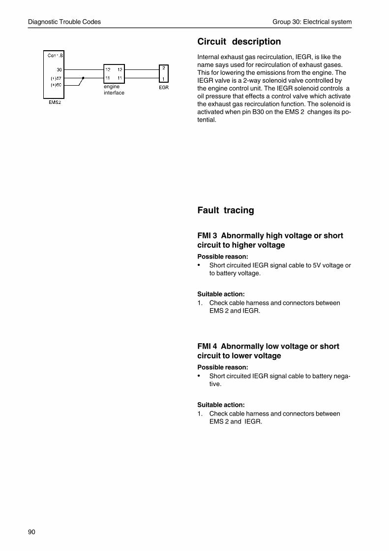
Diagnostic Trouble Codes Group 30: Electrical system
90
Circuit description
Internal exhaust gas recirculation, IEGR, is like thename says used for recirculation of exhaust gases.This for lowering the emissions from the engine. TheIEGR valve is a 2-way solenoid valve controlled bythe engine control unit. The IEGR solenoid controls aoil pressure that effects a control valve which activatethe exhaust gas recirculation function. The solenoid isactivated when pin B30 on the EMS 2 changes its po-tential.
Fault tracing
FMI 3 Abnormally high voltage or shortcircuit to higher voltagePossible reason:• Short circuited IEGR signal cable to 5V voltage or
to battery voltage.
Suitable action:1. Check cable harness and connectors between
EMS 2 and IEGR.
FMI 4 Abnormally low voltage or shortcircuit to lower voltagePossible reason:• Short circuited IEGR signal cable to battery nega-
tive.
Suitable action:1. Check cable harness and connectors between
EMS 2 and IEGR.
engineinterface

Group 30: Electrical system Diagnostic Trouble Codes
91
FMI 5 Abnormally low current or opencircuitPossible reason:• An open circuit in one or both of the cables to the
IEGR.
Suitable action:1. Check cable harness and connectors between
EMS 2 and IEGR.
2. Check IEGR coil.
FMI 7 Mechanical faultPossible reason:• IEGR solenoid mechanically stucked.
• Too low oil pressure to activate the IEGR.
Suitable action:1. Check function of IEGR solenoid.
2. Check engine oil pressure.
MeasurementsNOTE! If any of the measurements shows an abnor-mal value, check the wiring to and from the engine in-terface.
Checking the wiring:1. NOTE! Cut the current with the main switch.
2. Remove the connector to the IEGR solenoid.
3. Remove connector B from the EMS 2.
4. Connect the B connector to brakeout cable9990014 with measurebox 9998699.
5. Use multimeter 9812519 to do a resistance mea-surement.
Measurement points in box Nominal value
30 (IEGR signal) - R ≈ 0 Ω 2 (IEGR connector)
57, 60 (relay +) - R ≈ 0 Ω 1 (IEGR connector)

Diagnostic Trouble Codes Group 30: Electrical system
92
Checking IEGR coil
1. NOTE! Cut the current with the main switch.
2. Remove the connector from the IEGR solenoid .
3. Use multimeter 9812519 to measure the resis-tance in the IEGR coil.
Measurement points Nominal value
1 – 2 R ≈ 28 – 42 Ω
Checking IEGR solenoid
1. NOTE! Cut the current with the main switch.
2. Remove the IEGR solenoid.Please see the workshop manual for TAD650-760VE Group 21-26, for reference how to removethe IEGR solenoid.
3. Connect a 24 volt power supply to the IEGR elec-trical connection. The solenoid should now makea click when alter its position.

Group 30: Electrical system Diagnostic Trouble Codes
93
MID 128, PPID 55
ECU temperature
MID 128: Engine control unit
FMI 0: The sensor value is valid but above the nor-mal working range.
FMI 4: The voltage is less than the normal value oris short circuited to lower voltage.
FMI 5: The current is less than the normal value oris open circuited.
FMI Fault code explanation
0 ECU temperature is too high
4, 5 Faulty sensor / Faulty sensor circuit
Fault indicationDCU: Engine warning in DCU display.
CIU: None
Flash codeElectrical fault: 8.4
Value fault: None
SymptomNone.

Diagnostic Trouble Codes Group 30: Electrical system
94
Circuit description
The temperature sensor is installed inside of the EMS2 unit.
Fault tracing
FMI 0Fault condition:The temperature inside the engine control unit is toohigh.
Possible reason:• High surrounding temperature.
• Fault in sensor.
Suitable action:1. Check if the surrounding temperature is high or if
the EMS 2 unit is exposed to heat radiation.
2. Change EMS 2 unit.
FMI 4 The voltage is less than the normalvalue or is short circuited to lowervoltage.Possible reason:• Fault in sensor circuit.
Suitable action:1. Change EMS 2 unit.
FMI 5 Abnormally low current or opencircuitPossible reason:• Fault in sensor circuit.
Suitable action:1. Change EMS 2 unit.

Group 30: Electrical system Diagnostic Trouble Codes
95
MID 128, PPID 98
Engine sync acknowledge
MID 128: Engine control unitFMI 9: Abnormal updating frequency on the sec-
ondary bus.
FMI Fault code explanation
9 Communication fault
Fault indicationDCU Engine warning in DCU display.
CIU Flashcode
Flash codeElectrical fault: None

Diagnostic Trouble Codes Group 30: Electrical system
96
Fault tracingNOTE! If the control panel ONLY communicates onthe J1939 communication and NOT the redundancy ofJ1587 for start, stop and throttle this fault code is ac-tive in the VODIA and that is normal.
FMI 9Fault condition:“Time-out” on the J1587 bus.
Possible reason:• Fault in the communication with the DCU/CIU.
• No DCU/CIU found.
• Open circuit in the power supply cable betweenthe engine control unit and the DCU/CIU.
• Faulty DCU/CIU.
Suitable action1. Check communication cables to the DCU/CIU.
2. Check power supply cable between engine controlunit and DCU/CIU.
3. Check that DCU/CIU is programmed for correctengine type.

Group 30: Electrical system Diagnostic Trouble Codes
97
MID 128 / 144, PPID 132
Throttle input request failure, DCU/CIU
MID 128: Engine control unitMID 144: Control interface unitFMI 3: The voltage exceeds the normal value or is
short circuited to higher voltage.
FMI 4: The voltage is less than the normal value oris short circuited to battery negative.
FMI 9: Abnormal update rate
FMI Fault code explanation
3, 4 Faulty throttle potentiometer /Faulty throttle potentiometer circuit
9 EMS2 is missing the throttle signal
Fault indicationDCU: Engine warning in DCU display.
CIU: Flashcode
Flash codeElectrical fault: 2.8
Value fault: None
SymptomEngine goes to idle. If the accelerator is released atfirst and then pressed down again the engine can beforced to run using the idle contact.

Diagnostic Trouble Codes Group 30: Electrical system
98
Fault tracingNOTE! If the control panel ONLY communicates onthe J1939 communication and NOT the redundancy ofJ1587 for start, stop and throttle this fault code is ac-tive in the VODIA and that is normal.
FMI 3 Abnormally high voltage or shortcircuit to higher voltagePossible reason:• Open circuit in any or all of the throttle signals.
• Short circuited throttle potentiometer signal cableto 5V voltage or to battery voltage.
• Faulty throttle potentiometer.
Suitable action:1. Check that the throttle potentiometer is connected
correctly.
2. Check cable harness and connectors betweenCIU and CIU throttle potentiometer.
3. Check function of throttle potentiometer.
4. Check contact pressure in socket 2, 3 and 30 inCIU connector.
FMI 4 Abnormally low voltage or shortcircuit to lower voltagePossible reason:• Short circuited throttle potentiometer signal cable
to battery negative.
• Faulty throttle potentiometer.
Suitable action:1. Check that the throttle potentiometer is connected
correctly.
2. Check cable harness and connectors betweenCIU and CIU throttle potentiometer.
3. Check function of throttle potentiometer.

Group 30: Electrical system Diagnostic Trouble Codes
99
FMI 9Fault condition:EMS2 gets no throttle signal on the J1939 bus fromthe CIU.
Suitable action:1. Check that the throttle potentiometer is connected
correctly.
2. Check cable harness and connectors betweenCIU and CIU throttle potentiometer.
3. Check function of throttle potentiometer.
4. Check contact pressure in socket 2, 3 and 30 inCIU connector.
Logging throttle signal withVodiaTo verify the throttle signal on the J1587 bus do asfollow:
1. Choose “Log test” under the “Service and mainte-nance” meny.
2. Choose “MID 128, Accelerator Pedal Position”and “MID 144, Throttle Calibrated Position” andpress play.
3. Verify that booth throttle values displayed in per-centage by Vodia changes simultaneous whilemoving the throttle.

Diagnostic Trouble Codes Group 30: Electrical system
100
MID 128, SID 1-6
Injector common rail # 1-6
MID 128: Engine control unit.
FMI 3: Short to battery voltage, injector low voltageside.
FMI 4: Short to battery negative, injector high volt-age side.
FMI 5: Break in injector circuit.
FMI 7: Mechanical fault. The system responds in-correctly.
FMI 12: Low injector hold current.
FMI 14: Special instructions.
FMI Fault code explanation
3, 4, 5, 7, 12 Fault in the injection system
Fault indicationDCU: Engine warning in DCU display.
CIU: Flash code
Flash codeElectrical fault: 7.1– 7.6
Value fault: None
SymptomFMI 3, 4, 5 : Faulty injector is shut off. Limp home
on rest of injectors.

Group 30: Electrical system Diagnostic Trouble Codes
101
Circuit description
The electronic injectors used on the engine has anelectronically controlled solenoid. The solenoid is con-trolled by the engine control unit.
The injectors receive voltage from pin A59 orA 60 onthe engine control unit. To activate an injector solenoidthe engine control unit grounds the current injector.
Fault tracingNOTE! Identify which injector by the SID number.
FMI 3 Checking injector circuitConditions for fault code:
Injector activated and faulty voltage in injector lowside
Possible reason:• Short circuit to battery voltage on the pin on the
respective injector’s low voltage side. (EMS 2 pin:56, 52, 48 and 44, 40, 36)
• Short circuit between high voltage and low voltageside.
• Short circuit to battery voltage in low voltage in-jector wire.
Suitable action:1. Check cable harness and connectors between in-
jectors and engine control unit (EMS 2).
engineinterface
splice
splice
Note! Only TAD 650, 660, 750, 760 has an engine interface. OnTAD 734 the wiring to the EMS 2 is the same but without any en-gine interface.

Diagnostic Trouble Codes Group 30: Electrical system
102
FMI 4 Checking injector circuitConditions for fault code:
Injector activated and faulty voltage in injector highside.
Possible reason:• Short circuit to battery negative on the pin on the
respective injector’s high voltage side. (EMS 2pin: 59 and 60)
• Short circuit to battery negative in high voltage in-jector wire.
Suitable action:1. Check cable harness and connectors between in-
jectors and engine control unit (EMS 2).
FMI 5 Checking injector circuitConditions for fault code:
Injector activated and faulty voltage in injector high orlow side.
Possible reason:• An open circuit in low voltage wiring side or high
voltage wiring side.
• If three injection fault codes are set there is anopen circuit on the high side. If one injection faultcode is set there is an open circuit on the lowside.
• Short circuit to battery voltage on the pin on therespective injector’s high voltage side. (EMS 2pin: 59 and 60)
• Short circuit to battery negative on the pin on therespective injector’s low voltage side. (EMS 2 pin:56, 52, 48 and 44, 40, 36)
Suitable action:1. Check contact pressure in socket 36, 40, 44 ,52,
56, 59 and 60 in engine connector A.
2. Check cable harness and connectors between in-jectors and engine control unit (EMS 2).

Group 30: Electrical system Diagnostic Trouble Codes
103
FMI 7Conditions for fault code:
Injector activated and cylinder balancing above limit.
If a fault code is set when the engine has an unsym-metrical load it can not be rectified. At idle speed theengine control unit is trying to compensate for unevenrunning by adding more or less fuel to the injectors,cylinder balancing. If the engine load is too unsymmet-rical the compensation is not enough and a fault codewill be set.
Possible reason:• Unsymmetrical load of the engine.
• Poor / uneven compression.
• Faulty injector.
Suitable action:1. Clear the fault code with the Vodia tool. Let the
engine run at idle speed without any load and seeif the fault code reappear.
2. Perform test of cylinder compression using theVODIA tool.
3. Change only the faulty injector.
FMI 12 Checking injector circuitConditions for fault code:
Low injector hold current. Injector activated.
Possible reason:• Intermittent fault.
Suitable action:1. Check cables harness and connectors between
injector and engine control unit.

Diagnostic Trouble Codes Group 30: Electrical system
104
FMI 14Conditions for fault code:
Low or high flow through injector.
Possible reason:• Faulty injector: leakage in spill valve, increased
nozzle hole.
Suitable action:1. Change only the faulty injector.
Measurements
NOTE! If any of the measurements shows an abnor-mal value, check the wiring to and from the engine in-terface.
• NOTE! Cut the current with the main switch.
• Remove both wires that are connected to the in-jector that is to be measured.
• Remove connector A from the EMS 2.
• Use multimeter 9812519 to do a resistance mea-surement between connector A from the EMS 2 tothe loosened wires from the injector. See circuitdescription which pin in the connector A to mea-sure from.
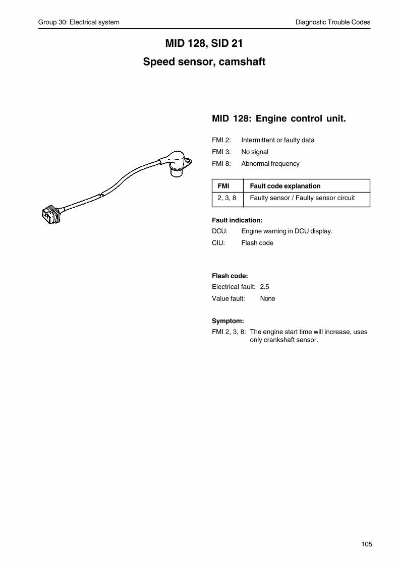
Group 30: Electrical system Diagnostic Trouble Codes
105
MID 128, SID 21
Speed sensor, camshaft
MID 128: Engine control unit.
FMI 2: Intermittent or faulty data
FMI 3: No signal
FMI 8: Abnormal frequency
FMI Fault code explanation
2, 3, 8 Faulty sensor / Faulty sensor circuit
Fault indication:
DCU: Engine warning in DCU display.
CIU: Flash code
Flash code:
Electrical fault: 2.5
Value fault: None
Symptom:
FMI 2, 3, 8: The engine start time will increase, usesonly crankshaft sensor.

Diagnostic Trouble Codes Group 30: Electrical system
106
Circuit description
The camshaft sensor is an inductive sensor. Whenthe camshaft rotates impulses are created in the sen-sor via a tooth wheel installed on the camshaft. Thetooth wheel has 7 teeth, one for each cylinder + oneto determine when cylinder one is to be injected. Theimpulses create a pulse signal in the sensor that theengine control unit (EMS 2) uses to calculate when acylinder is in turn for injection.
Fault tracing
FMI 2 Checking sensor circuitConditions for fault code:
Incorrect timing.
Possible reason:
• Polarity fault. The cables to the cam sensor isshifted.
• Intermittent fault.
• Incorrectly mounted cam sensor.
Suitable action:
1. Check cable harness and connectors betweencam sensor and EMS 2.
2. Check that the cam sensor is connected as in thecircuit description.
3. Check contact pressure in socket 45 and 46 inengine connector A.
4. Check function of cam sensor.
speed sensor,camshaft
Note! Only TAD 650, 660, 750, 760 has an engine interface. OnTAD 734 the wiring to the EMS 2 is the same but without any en-gine interface.
engineinterface
Group 30: Electrical system Diagnostic Trouble Codes
107
FMI 3 Checking sensor circuitConditions for fault code:
No sensor signal when expected.
Possible reason:• Incorrectly mounted cam sensor.
• An open circuit in any or both of the cables to thecam sensor.
• Short circuit between cables to cam sensor.
• Faulty cam sensor.
Suitable action:1. Check installation of cam speed sensor.
2. Check cable harness and connectors betweencam sensor and EMS 2.
3. Check contact pressure in socket 45 and 46 inengine connector A.
4. Check function of cam sensor.
FMI 8 Checking sensor circuitConditions for fault code:
Incorrect sensor signal.
Possible reason:• Incorrectly mounted speed sensor.
• Electrical interference in the speed signal.
Suitable action:1. Check wiring between cam sensor and EMS 2.
2. Check contact pressure in socket 45 and 46 inengine connector A.
3. Check installation of cam sensor.
4. Attempt to localize the source of interference.
5. Check function of cam sensor.

Diagnostic Trouble Codes Group 30: Electrical system
108
MeasurementsNOTE! If any of the measurements shows an abnor-mal value, check the wiring to and from the engine in-terface.
• NOTE! Cut the current with the main switch.
• Remove the connector from the sensor. Connectadapter cable 885675 to the connector.
• Remove connector A from the EMS 2.
• Use multimeter 9812519 to do a resistance mea-surement from the sensor connector to connectorA to verify that neither of the wires are broken orshort circuited.
Measurement points Nominal value
1 (sensor conn.) – 46 (conn. A) R ≈ 0 Ω
2 (sensor conn.) – 45 (conn. A) R ≈ 0 Ω
1 (sensor conn.) – 2 (sensor conn.) R ≈ ∞ Ω

Group 30: Electrical system Diagnostic Trouble Codes
109
Checking camshaft positionsensor
1. NOTE! Cut the current with the main switch.
2. Undo the connector from the sensor and removethe sensor from the cylinder head.Check that the sensor does not have any externaldamage, or any swarf which has got stuck on it.
3. Connect adapter cable 885675 to sensor.
NOTE! Do not connect the other end of the adaptercable to the engine cable harness, since this cancause a measurement error.
4. Use multimeter 9812519 for resistance measure-ment.
Measurement points Nominal value
1 – 2 R ≈ 3,5 kΩ at 20°C
NOTE! The measurement must exclude short circuitor open circuit to the engine control unit.
5. Use multimeter 9812519 for a AC voltage mea-surement.Move a metal object rapidly back and forwardsnot more than 1 mm in front of the sensor. Checkthat the multimeter gives a reading.
6. Install the sensor.

Diagnostic Trouble Codes Group 30: Electrical system
110
MID 128, SID 22
Speed sensor, crankshaft
MID 128: Engine control unit
FMI 2: Intermittent or faulty data
FMI 3: No signal
FMI 8: Abnormal frequency
FMI Fault code explanation
2, 3, 8 Faulty sensor / Faulty sensor circuit
Fault indication:
DCU: Engine warning in DCU display.
CIU: Flash code
Flash code
Electrical fault: 2.4
Value fault: None
Symptom
FMI 3: Engine is running with imprecise timingcausing risk of high fuel consumption andsmoke. Cylinder balancing not workingwith risk of uneven running.
FMI 2, 8: Engine is difficult to start, uses only camsensor.

Group 30: Electrical system Diagnostic Trouble Codes
111
Circuit descriptionThe speed sensor is an inductive sensor. When thecrankshaft rotates impulses are created in the sensorvia a tooth wheel on or behind the torsion damper. Theimpulses create a pulse signal in the sensor that theengine control unit (EMS 2) uses to calculate thecrankshaft rpm.
The tooth wheel has a tooth free gap for the EMS 2 torecognize the position of the crankshaft.
Fault tracing
FMI 2 Checking sensor circuitConditions for fault code:
Incorrect signal.
Possible reason:
• Short circuit between cables to speed sensor.
• Polarity fault. The cables to the speed sensor isshifted.
Suitable action:
1. Check cable harness and connectors betweenspeed sensor and EMS 2.
2. Check that speed sensor is connected as in thecircuit description.
3. Check function of speed sensor.
speed sensor,crankshaft
Note! Only TAD 650, 660, 750, 760 has an engine interface. OnTAD 734 the wiring to the EMS 2 is the same but without any en-gine interface.
engineinterface

Diagnostic Trouble Codes Group 30: Electrical system
112
FMI 3 Checking sensor circuitConditions for fault code:
No sensor signal when expected or permanent loss ofsensor signal.
Possible reason:
• Open circuit in any or both of cables to the speedsensor.
• Incorrectly mounted speed sensor.
• Faulty speed sensor.
Suitable action:
1. Check cable harness and connectors betweenspeed sensor and EMS 2.
2. Check contact pressure in socket 37 and 38 inengine connector A.
4. Check installation of speed sensor.
5. Check function of speed sensor.
FMI 8 Checking sensor circuitConditions for fault code:
Incorrect speed sensor signal.
Possible reason:
• Incorrectly mounted speed sensor.
• Electrical interference in the sensor signal.
Suitable action:
1. Check wiring and connectors between speed sen-sor and EMS 2.
2. Check contact pressure in socket 37 and 38 inengine connector A.
3. Check installation of speed sensor.
4. Attempt to localize the source of interference.
5. Check and clean the speed sensor.

Group 30: Electrical system Diagnostic Trouble Codes
113
MeasurementsNOTE! If any of the measurements shows an abnor-mal value, check the wiring to and from the engine in-terface.
• NOTE! Cut the current with the main switch.
• Remove the connector from the sensor.
• Connect adapter cable 885675 to the cable har-ness connector to the engine control unit.
• Remove connector A from the EMS 2.
• Use multimeter 9812519 to do a resistance mea-surement from the sensor connector to connectorA, to verify that neither of the wires are broken orshort circuited.
Measurement points Nominal value
1 (sensor conn.) – 38 (conn. A) R ≈ 0 Ω
2 (sensor conn.) – 37 (conn. A) R ≈ 0 Ω
1 (sensor conn.) – 2 (sensor conn.) R ≈ ∞ Ω

Diagnostic Trouble Codes Group 30: Electrical system
114
5. Use multimeter 9812519 for a AC voltage mea-surement.
Move a metal object rapidly back and forwardsnot more than 1 mm in front of the sensor. Checkthat the multimeter gives a reading.
6. Install the sensor.
Checking speed sensor
1. NOTE! Cut the current with the main switch.
2. Undo the connector from the sensor and removethe sensor from the cylinder head.Check that the sensor does not have any externaldamage, or any swarf which has got stuck on it.
3. Connect adapter cable 885675 to sensor.
NOTE! Do not connect the other end of the adaptercable to the engine cable harness, since this cancause a measurement error.
4. Use multimeter 9812519 for resistance measure-ment.
Measurement points Nominal value
1 – 2 R ≈ 0,9 kΩ at 20°C
NOTE! The measurement must exclude short circuitor open circuit to the engine control unit.
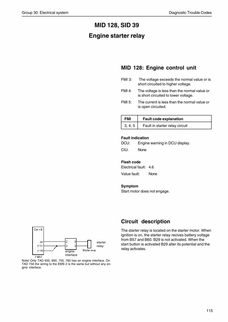
Group 30: Electrical system Diagnostic Trouble Codes
115
Circuit description
The starter relay is located on the starter motor. Whenignition is on, the starter relay recives battery voltagefrom B57 and B60. B29 is not activated. When thestart button is activated B29 alter its potential and therelay activates.
MID 128, SID 39
Engine starter relay
MID 128: Engine control unit
FMI 3: The voltage exceeds the normal value or isshort circuited to higher voltage.
FMI 4: The voltage is less than the normal value oris short circuited to lower voltage.
FMI 5: The current is less than the normal value oris open circuited.
FMI Fault code explanation
3, 4, 5 Fault in starter relay circuit
Fault indicationDCU: Engine warning in DCU display.
CIU: None
Flash codeElectrical fault: 4.6
Value fault: None
SymptomStart motor does not engage.
starterrelay
engineinterface
Note! Only TAD 650, 660, 750, 760 has an engine interface. OnTAD 734 the wiring to the EMS 2 is the same but without any en-gine interface.

Diagnostic Trouble Codes Group 30: Electrical system
116
Fault tracing
at starter motor problems:
• Check battery condition.
• Check wiring to start motor.
• Check that starter relay click when start button isactivated.
FMI 3Conditions for fault code:
Short circuit too battery voltage.
Possible reason:• Short circuit in starter relay cable.
• Faulty starter relay.
Suitable action:1. Check cable harness and connections between
starter relay and EMS 2.
2. Check function of starter relay.
FMI 4Conditions for fault code:
Short circuit too battery negative.
Possible reason:• Short circuit in starter relay cable.
• Faulty starter relay.
Suitable action:1. Check cable harness and connections between
starter relay and EMS 2.
2. Check function of starter relay.

Group 30: Electrical system Diagnostic Trouble Codes
117
FMI 5Conditions for fault code:
Open circuit.
Possible reason:• An open circuit in starter relay cable.
• Faulty starter relay.
Suitable action:1. Check cable harness and connections between
starter relay and EMS 2.
2. Check contact pressure in socket B29 in engineconnector.
3. Check function of starter relay.
Measurements
Checking starter relay coil
1. NOTE! Cut the current with the main switch.
2. Remove one of the wires to the starter relay.
3. Use multimeter 9812519 to measure the resis-tance in the coil.
Measurement points Nominal value
Relay connectors R ≈ 9 – 15 Ω
Checking starter relay voltage supply
1. Turn ignition off.
2. Connect multimeter 9812519 to do a voltage mea-surement over the starter relay.
3. Turn ignition on.
Measurement points Nominal value
Relay connectors V ≈ 0 V
4. Push start button.
Measurement points Nominal value
Relay connectors V ≈ Battery Voltage

Diagnostic Trouble Codes Group 30: Electrical system
118
MID 128, SID 42
Injection control pressure regulator
MID 128: Engine control unit
FMI 3: The voltage exceeds the normal value or isshort circuited to higher voltage.
FMI 4: The voltage is less than the normal value oris short circuited to lower voltage.
FMI 5: The current is less than the normal value oris open circuited.
FMI 6: The current is greater than the normal valueor is short circuited to battery negative.
FMI 13: Calibration value of range
FMI Fault code explanation
3, 4, 5, 6, 13 Faulty regulator /Faulty regulator circuit
Fault indicationDCU: Engine warning in DCU display
CIU: None
Flash codeElectrical fault: 8.3
Value fault: None
SymptomAll FMI: Full fuel flow delivery. Limp home with
pressure release valve opened.
FMI 5, 13: Possible stall of engine.

Group 30: Electrical system Diagnostic Trouble Codes
119
Component description
A magnetically controlled proportional valve (MPROP)controls the fuel pressure (rail pressure) to ensure thatthe correct fuel pressure is retained despite varyingengine speed and loading. Signal from engine controlunit is a PWM signal (pulse width modulated signal).When the current through the valve is changed, thisaffects the fuel flow, which results in changed railpressure. The rail pressure sensor senses the pres-sure and converts the pressure signal to a voltagewhich is registered by the engine control unit. If thecurrent to the valve solenoid rises, the less fuel pres-sure (rail pressure) is obtained. So if a wire breaks fullfuel flow will be achieved.
Fault tracing
FMI 3 Abnormally high voltage or shortcircuit to higher voltagePossible reason:• Short circuit to battery voltage in MPROP nega-
tive cable, pin 2 on MPROP.
Suitable action:1. Check cable harness and connectors between
EMS 2 and MPROP.
FMI 4 Abnormally low voltage or shortcircuit to lower voltagePossible reason:• Short circuit to battery negative in MPROP posi-
tive wire, pin 1 on MPROP.
Suitable action:1. Check cable harness and connectors between
EMS 2 and MPROP.
Note! Only TAD 650, 660, 750, 760 has an engine interface. OnTAD 734 the wiring to the EMS 2 is the same but without any en-gine interface.
Magnetic proprotionalvalve (MPROP)
engineinterface

Diagnostic Trouble Codes Group 30: Electrical system
120
FMI 5 The current is less than the normalvalue or is open circuitedPossible reason:• An open circuit in one or both cables from EMS 2
to MPROP.
• Short circuit to battery negative in MPROP posi-tive wire, pin 1 on MPROP.
• Short circuit between both wires to MPROP.
• Short circuit to battery voltage in MPROP positivewire, pin 1 on MPROP.
Suitable action:1. Check contact pressure in socket 12 and 16 in
engine connector A. Also check contact pressurein connector at MPROP.
2. Check cable harness and connectors betweenEMS 2 and MPROP.
FMI 6 The current is greater than thenormal value or is short circuited tobattery negativePossible reason:• Short circuit to battery negative in MPROP nega-
tive cable, pin 2 on MPROP.
• An open circuit in one or both cables from EMS 2to MPROP.
Suitable action:1. Check contact pressure in socket 12 and 16 in
engine connector A. Also check contact pressurein connector at MPROP.
2. Check cable harness and connectors betweenEMS 2 and MPROP
FMI 13Possible reason:• Short circuit to battery negative in MPROP nega-
tive cable, pin 2 on MPROP.
Suitable action:1. Check cable harness and connectors between
EMS 2 and MPROP.

Group 30: Electrical system Diagnostic Trouble Codes
121
Measurements
NOTE! If any of the measurements shows an abnor-mal value, check the wiring to and from the engine in-terface.
Checking the wiring:• NOTE! Cut the current with the main switch.
• Remove the connector to the MPROP.
• Remove connector A from the EMS 2.
• Use multimeter 9812519 to do a resistance mea-surement against the engine control unit connec-tor A.
Measurement points Nominal value
2 (885675) – 16 (EMS 2, conn.A) R ≈ 0 Ω
2 (885675) – 12 (EMS 2, conn.A) R ≈ ∞ Ω
1 (885675) – 16 (EMS 2, conn.A) R ≈ ∞ Ω
1 (885675) – 12 (EMS 2, conn.A) R ≈ 0 Ω

Diagnostic Trouble Codes Group 30: Electrical system
122
MID 128, SID 70
Preheat sense
MID 128: Engine control unit
FMI 3: The voltage exceeds the normal value or isshort circuited to higher voltage.
FMI 4: The voltage is less than the normal value oris short circuited to lower voltage.
FMI 5: The current is less than the normal value oris open circuited.
FMI Fault code explanation
3, 4, 5 Faulty relay / Faulty relay circuit
Fault indicationDCU: Engine warning in DCU display.
CIU: None
Flash codeElectrical fault: None
Value fault: None
SymptomFMI 3: Fuse for shorting wire breaks.
FMI 4: Start problems in cold climate.
FMI 5: Might get start problems in cold climate.

Group 30: Electrical system Diagnostic Trouble Codes
123
Fault tracing
FMI 3 Abnormally high voltage or shortcircuit to higher voltagePossible reason:• Short circuit to battery voltage in sense wire.
• Heating element broken.
Suitable action:1. Check cable harness and connectors to heating
element.
2. Check function of preheat relay.
3. Change heating element.
FMI 4 Abnormally low voltage or shortcircuit to lower voltagePossible reason:• Short circuit to battery negative in sense wire.
Suitable action:1. Check function of preheat relay.
2. Check cable harness and connectors to heatingelement.
FMI 5Possible reason:• An open circuit in sense wiring.
• Heating element broken.
Suitable action:1. Check contact pressure in socket 7 in engine con-
nector B.
2. Check cable harness and connections to heatingelement.
3. Change heating element.

Diagnostic Trouble Codes Group 30: Electrical system
124
MID 128, SID 211
5V sensor supply 2
MID 128: Engine control unit
FMI 3: The voltage exceeds the normal value or isshort circuited to higher voltage.
FMI 4: The voltage is less than the normal value oris short circuited to lower voltage.
FMI Fault code explanation
3, 4 Faulty sensor / Faulty sensor circuit
Fault indicationDCU: Engine warning in DCU display.
CIU: None
Flash codeElectrical fault: 9.3
Value fault: None
SymptomNone

Group 30: Electrical system Diagnostic Trouble Codes
125
Fault tracing
FMI 3 Abnormally high voltage or shortcircuit to higher voltageConditions for fault code:
The voltage exceeds the normal value or is short cir-cuited to higher voltage.
Possible reason:• Short circuit between 5V supply voltage and bat-
tery voltage in EMS 2 connector B.
Suitable action:1. Check all 5V supply cables distributed by EMS 2
connector B. (see EMS 2 wiring diagram)
FMI 4 Abnormally low voltage or shortcircuit to lower voltagePossible reason:• Short circuit between the supply cables to the oil
pressure sensor.
• Short circuit between the supply cables to the fuelpressure sensor.
Suitable action:1. Check the sensor supply cables to oil pressure
sensor.
2. Check the sensor supply cables to fuel pressuresensor.

Diagnostic Trouble Codes Group 30: Electrical system
126
MID 128, SID 231
Communication fault J 1939
MID 128: Engine control unitMID 144: DCU/CIU
FMI 2: Intermittent or faulty data.
FMI Fault code explanation
2 Communication fault J 1939
Fault indicationDCU: Engine warning in DCU display.
CIU: Flash code
Flash codeElectrical fault: 6.5 (EMS)
Value fault: None (EMS)
Electrical fault: 6.4 (CIU)
Value fault: None (CIU)
SymptomEngine can not be started or if engine is running it canonly be stopped by pushing the aux-stop.

Group 30: Electrical system Diagnostic Trouble Codes
127
Cable description
Fault tracing
FMI 2 Checking circuitConditions for fault code:
CAN communication is missing.
Possible reason:• CAN H and CAN L short circuited to each other.
• CAN H or CAN L short circuited to battery nega-tive on pin 3.
• CAN L short circuited to power supply on pin 4.
• CAN H or CAN L short circuited to any of theJ1708 links.
Suitable action:1. Check all data links between DCU/CIU and
EMS 2.
CAN H-datalink to engine
CAN L-datalink to enginePower supply
Power supply input
IgnitionStop
J1708A-datalink to engine
J1708B-datalink to engine
B55B51
A58A27
A33A34

Diagnostic Trouble Codes Group 30: Electrical system
128
Measurements
Checking the CAN bus cable. The resistance of theCAN bus termination resistors, one 120 Ω resistor inthe ECU and one 120 Ω resistor in the cable harness,are measured.
• NOTE! Cut the current with the main switch.
• Disconnect the 8-pin Deutsch connector at theDCU or disconnect at the CIU.
• Use multimeter 9812519 to do resistance mea-surement towards the EMS 2.
Measurement points Nominal valuein the engine connectorat the DCU
1 – 2 U ≈ 60 Ω
or
Measurement points Nominal valuein the CIU connector
11 – 12 U ≈ 60 Ω
NOTE! Even if the measured value equals the nomi-nal value the data bus cable could be faulty due toshortcircuit between a data bus cable and another ca-ble in the harness.
• Connect adapter cable 88890016 with measure-box 9998699 between the EMS 2 and the CIU/DCU.
• Use multimeter 9812519 to a voltage measure-ment.
• Turn ignition on.
Measurement points Nominal valuein the measurebox
16 – 17 (between CAN bus) U ≈ 2.3 V – 2.7 V
NOTE! Even if the measured value equals the nomi-nal value the data bus cable could be faulty due toshortcircuit between a data bus cable and another ca-ble in the harness.

Group 30: Electrical system Diagnostic Trouble Codes
129
MID 128, SID 232
5V sensor supply 1
MID 128: Engine control unit
FMI 3: The voltage exceeds the normal value or isshort circuited to higher voltage.
FMI 4: The voltage is less than the normal value oris short circuited to lower voltage.
FMI Fault code explanation
3, 4 Faulty sensor / Faulty sensor circuit
Fault indicationDCU: Engine warning in DCU display.
CIU: None
Flash codeElectrical fault: 9.3
Value fault: None
SymptomNone
Diagnostic Trouble Codes Group 30: Electrical system
130
Fault tracing
FMI 3 Abnormally high voltage or shortcircuit to higher voltageConditions for fault code:
The voltage exceeds the normal value or is short cir-cuited to higher voltage.
Possible reason:• Short circuit between 5V supply voltage and bat-
tery voltage in EMS 2 connector A.
Suitable action:1. Check all 5V supply cables distributed by EMS 2
connector A. (see EMS 2 wiring diagram)
FMI 4 Abnormally low voltage or shortcircuit to lower voltagePossible reason:• Short circuit between the supply cables to the
boost pressure sensor.
• Short circuit between the supply cables to the railpressure sensor.
Suitable action:1. Check the sensor supply cables to boost pressure
sensor.
2. Check the sensor supply cables to rail pressuresensor.
Group 30: Electrical system Diagnostic Trouble Codes
131
MID 128, SID 240
Program memory
MID 128: Engine control unit
FMI 2: Intermittent or faulty data.
FMI 7: Mechanical fault. The system responds in-correctly.
FMI 11: Unidentified fault.
FMI 14: Special instruction.
FMI Fault code explanation
2, 7, 11, 14 Communication fault
Fault indicationDCU: Engine warning in DCU display.
CIU: Flash code
Flash codeElectrical fault: 9.9
Value fault: None
SymptomThe engine can not be started.
Fault tracing
FMI 2, 7, 11, 14Conditions for fault code:
Checksum error.
Possible reason:• Downloading interrupted.
• Internal fault in the engine control unit.
Suitable action:1. Reprogram the engine control unit.
2. Change the engine control unit.

Diagnostic Trouble Codes Group 30: Electrical system
132
MID 128, SID 254
Controller error
MID 128: Engine control unitMID 144: DCU/CIU
FMI 3: RAM addressing failure.
FMI 8: Abnormal frequency.
FMI 12: Faulty unit or component.
FMI Fault code explanation
3, 8, 12 Faulty component
Fault indicationDCU: Engine warning in DCU display.
CIU: Flash code
Flash codeElectrical fault: 9.9 (EMS)
Value fault: None (EMS)
Electrical fault: 9.8 (CIU)
Value fault: None (CIU)
SymptomThe engine can not be started.
Fault tracing
FMI 3, 8, 12Conditions for fault code:
Internal fault in the engine control unit.
Suitable action:1. Replace the engine control unit.

Group 30: Electrical system Diagnostic Trouble Codes
133
MID 128, PSID 96
Rail pressure system
MID 128: Engine control unit
FMI 0: The sensor value is valid but above the nor-mal working range.
FMI 1: The sensor value is valid but below the nor-mal working range.
FMI 4: The voltage is less than the normal value oris short circuited to lower voltage.
FMI 7: Mechanical fault. The system responds in-correctly.
FMI 12: Faulty unit or component.
FMI Fault code explanation
0, 1, 4, 7, 12 Fault in rail pressure circuit
Fault indicationDCU: Engine warning in DCU display.
CIU: None
Lamp statusFMI 0, 12: Yellow lamp
FMI 1, 4, 7: Red lamp
Flash codeElectrical fault: 8.3
Value fault: None
SymptomFMI 0: Engine derated: engine speed limita-
tion (1100 rpm). Full fuel flow delivery.Limp home with pressure relief valveopened.
FMI 1, 7, 12: Engine derated: engine speed limita-tion (1100 rpm). Fuel pressure limita-tion (800 bar). Engine torque reduc-tion.
FMI 4: Engine derated: engine speed limita-tion (1100 rpm). Fuel pressure limita-tion (800 bar). Engine torque reduc-tion. Engine shut off or difficult tostart.

Diagnostic Trouble Codes Group 30: Electrical system
134
Fault tracing
FMI 0Conditions for fault code:
Rail pressure controller integral part too low.
Possible reason:• MPROP stuck open due to mechanical fault or an
open circuit in MPROP electrical wiring.
• Faulty rail pressure sensor.
• An injector does not open.
Suitable action:1. Check contact pressure in socket 12 and 16 in en-
gine connector A.
2. Check MPROP cables and connectors.
3. Check function of rail pressure sensor.
4. Change MPROP valve.
5. Check if an injector is faulty.
FMI 1Conditions for fault code:
Rail pressure controller integral part too big. High pres-sure leakage detected.
Possible reason:• High pressure leakage.
• Faulty rail pressure sensor.
• MPROP closed or partly closed or out of charac-teristic,
• Rail pressure release valve stuck open or unwant-ed opening.
• An injector is stuck open.
• Faulty high pressure pump.
Suitable action:1. Check fuel pipes for leakage (high pressure pipes,
suction pipes, return pipes).
2. Check function of rail pressure sensor (see MID128, PID 164).
3. Change the rail pressure release valve.
4. Check MPROP cables and connectors.
5. Change MPROP valve.
6. Check if an injector is faulty.
7. Check both high pressure pumps (see workshopmanual Group 21-26).

Group 30: Electrical system Diagnostic Trouble Codes
135
FMI 4Conditions for fault code:
Low rail pressure
Possible reason:• Low fuel level.
• Air gets into the fuel system.
• High pressure leakage.
• Low pressure leakage.
• Blocked fuel filter, pre- and fine filter.
• Faulty rail pressure sensor.
• MPROP closed or partly closed or out of charac-teristic,
• Rail pressure release valve stuck open or unwant-ed opening.
• An injector is stuck open.
• Faulty high pressure pump.
Suitable action:1. Check fuel level, hoses and fuel filter for leakage.
2. Check fuel pipes for leakage (high pressure pipes,suction pipes, return pipes).
3. Change fuel filters, pre- and fine filter.
4. Check function of rail pressure sensor (see MID128, PID 164).
5. Change the rail pressure release valve.
6. Check MPROP cables and connectors.
7. Change MPROP valve.
8. Check if an injector is faulty.
9. Check both high pressure pumps (see workshopmanual Group 21-26).
FMI 7Conditions for fault code:
Cylinder balancing exceeding upper threshold. Railpressure controller integral part too big.
Possible reason:• High pressure pipes rail to injector leakage, see
SID1-6 (FMI 7) for info which injector.
Suitable action:1. Check for leakage in the high pressure system.

Diagnostic Trouble Codes Group 30: Electrical system
136
FMI 12Conditions for fault code:
Rail pressure too low. Rail pressure nominal value de-viates positive from set point value.
Possible reason:• Low fuel level.
• Air gets into the fuel system.
• High pressure leakage.
• Low pressure leakage.
• Blocked fuel filter, pre- and fine filter.
• Faulty rail pressure sensor.
• MPROP closed or partly closed or out of charac-teristic,
• Rail pressure release valve stuck open or unwant-ed opening.
• An injector is stuck open.
• Faulty high pressure pump.
Suitable action:1. Check fuel level, hoses and fuel filter for leakage.
2. Check fuel pipes for leakage (high pressure pipes,suction pipes, return pipes).
3. Change fuel filters, pre- and fine filter.
4. Check function of rail pressure sensor (see MID128, PID 164).
5. Change the rail pressure release valve.
6. Check MPROP cables and connectors.
7. Change MPROP valve.
8. Check if an injector is faulty.
9. Check both high pressure pumps.

Group 30: Electrical system Diagnostic Trouble Codes
137
MID 128, PSID 97
Rail pressure release valve
MID 128: Engine control unit
FMI 0: The sensor value is valid but above the nor-mal working range.
FMI 7: Mechanical fault. The system responds in-correctly.
FMI 11: Unidentified fault.
FMI 14: Special instruction.
FMI Fault code explanation
0 Leakage detected in pressurerelease valve
7 Pressure release valve stuck close
11, 14 Pressure release valve open
Fault indicationDCU: Engine warning in DCU display.
CIU: None
Lamp statusFMI 0, 11, 14: Yellow lamp
FMI 7: Red lamp
Flash codeElectrical fault: 8.3
Value fault: None
SymptomFMI 0, 11: Engine derated: engine speed limitation
(1100 rpm). Fuel pressure limitation (800bar). Engine torque reduction.
FMI 7: Engine shut off after delay or engine derat-ed. Engine derated: engine speed limita-tion (1100 rpm). Fuel pressure limitation(800 bar). Engine torque reduction.
FMI 14: Engine derated: engine speed limitation(1100 rpm). Engine torque reduction. Fullfuel flow delivery. Limp home with pres-sure release valve opened.
Diagnostic Trouble Codes Group 30: Electrical system
138
Circuit description
The task of the pressure limiting valve (safety valve)is to protect the system from excess pressure. Thevalve opens and reduces the fuel pressure (rail pres-sure) by releasing fuel to the return pipe as neces-sary. The valve is a two-stage valve. Stage oneopens at about 190 MPa (1900 bar / 27557 psi) andstage 2 maintains the pressure at about 60 MPa (600bar / 8702 psi). If the MPROP valve* has been dam-aged and gives full flow, for example, the pressure re-lease valve reduces the fuel flow to about 60 MPa(600 bar / 8702 psi).
* NOTE! MPROP valve = Magnetically controlled pro-portional valve.
Fault tracing
FMI 0Conditions for fault code:
Leakage detected in rail pressure release valve, openmode.
Possible reason:• Rail pressure controller out of range.
• Faulty rail pressure release valve.
Suitable action:1. Check function of rail pressure sensor.
2. Change the rail pressure release valve.
Group 30: Electrical system Diagnostic Trouble Codes
139
FMI 7Conditions for fault code:
Rail pressure release valve stuck close.
Possible reason:• An open circuit in one or both cables from EMS 2
to MPROP.
• Short circuit to battery negative in MPROP posi-tive wire, pin 1 on MPROP.
• Rail pressure release valve stuck close.
Suitable action:1. Check contact pressure in socket 12 and 16 in
engine connector A. Also check contact pressurein connector at MPROP.
2. Check cable harness and connectors betweenEMS 2 and MPROP.
3. Change the rail pressure release valve.
FMI 11Conditions for fault code:
High rail pressure when rail pressure release valve isopen.
Possible reason:• Rail pressure controller out of range.
• Pressure release valve stuck close or out of char-acteristic.
Suitable action:1. Check function of rail pressure sensor.
2. Change the rail pressure release valve.
Diagnostic Trouble Codes Group 30: Electrical system
140
FMI 14Conditions for fault code:
Rail pressure release valve stuck open.
Possible reason:• Blocked fuel return line.
• An open circuit in one or both cables from EMS 2to MPROP.
• Short circuit to battery negative in MPROP nega-tive cable, pin 2 on MPROP.
• MPROP stuck open.
Suitable action:1. Check fuel return line.
2. Check contact pressure in socket 12 and 16 inengine connector A. Also check contact pressurein connector at MPROP.
3. Check cable harness and connector betweenEMS 2 and MPROP.
4. Change MPROP valve.

Group 30: Electrical system Diagnostic Trouble Codes
141
MID 128, PSID 201
J1939 communication bus
MID 128: Engine control unit
FMI 9: Abnormal updating rate.
FMI Fault code explanation
9 Communication error
Fault indicationDCU: Engine warning in DCU display.
CIU: None
Flash codeElectrical fault: None
Value fault: None
SymptomNone
Component descriptionCAN H-datalink to engine
CAN L-datalink to enginePower supply
Power supply input
IgnitionStop
J1708A-datalink to engine
J1708B-datalink to engine
B55B51
A58A27
A33A34

Diagnostic Trouble Codes Group 30: Electrical system
142
Fault tracing
FMI 9Conditions for fault code:
No communication with the engine control unit.
Possible reason:• An open circuit in CAN H or CAN L or both CAN
links between EMS 2 and DCU/CIU.
• An open circuit in Power supply 0V cable betweenEMS 2 and DCU/CIU.
• An open circuit in Power supply input cable be-tween EMS 2 and DCU/CIU.
• CAN H short circuited to power supply in pin 4.
Suitable action:1. Check contact pressure in socket 51 and 55 in
engine connector B.
2. Check for an open circuit or short circuit betweencables in the cable harness between the DCU/CIUand EMS 2, via the engine connector.

Group 30: Electrical system Diagnostic Trouble Codes
143
Measurements
Checking the CAN bus cable. The resistance of theCAN bus termination resistors, one 120 Ω resistor inthe ECU and one 120 Ω resistor in the cable harness,are measured.
• NOTE! Cut the current with the main switch.
• Disconnect the 8-pin Deutsch connector at theDCU or disconnect at the CIU.
• Use multimeter 9812519 to do resistance mea-surement towards the EMS 2.
Measurement points Nominal valuein the engine connectorat the DCU
1 – 2 U ≈ 60 Ω
or
Measurement points Nominal valuein the CIU connector
11 – 12 U ≈ 60 Ω
NOTE! Even if the measured value equals the nomi-nal value the data bus cable could be faulty due toshortcircuit between a data bus cable and another ca-ble in the harness.
• Connect adapter cable 88890016 with measure-box 9998699 between the EMS 2 and the CIU/DCU.
• Use multimeter 9812519 to a voltage measure-ment.
Measurement points Nominal valuein the measurebox
16 – 17 (between CAN bus) U ≈ 2.3 V – 2.7 V
NOTE! Even if the measured value equals the nomi-nal value the data bus cable could be faulty due toshortcircuit between a data bus cable and another ca-ble in the harness.

Engine protection Group 30: Electrical system
Engine protection
Derate to engine protection map
Parameter “Yellow lamp” “Red lamp” 0% 50% 70% 100% Forced to idle Forced shutdownafter 5 sec. after 15 sec.
High coolant 98 101 101 - - 106 >106 >106temperature (°C)
High boost 80 83 83 - - 90 >90 >90temperature (°C)
High boost 340 350 - 350 - - >355 >355pressure (kPa)
Low oil Limit 20<limit - - 20<limit - 25<limit 25<limitpressure (kPa)
Oil pressure limit
Pressure, kPa
Engine speed, rpm
Oil pressure limit
Engine protection
Engine speed, rpm
Torque, Nm
TAD 650, 660, 750, 760 VE

Group 30: Electrical system Engine protection
Engine protectionTAD 734 GE
Parameter “Yellow lamp” “Red lamp” Forced shutdown
High coolant 98 106 >106temperature (°C)
High oiltemperature (°C) 125 135 >135
High boost 80 90 >90temperature (°C)
High boost 340 355 >355pressure (kPa)
Low coolantlevel - switch switch
Low oil Limit 25<limit 25<limitpressure (kPa)
Oil pressure limit
0
50
100
150
200
250
300
0 500 1000 1500 2000 2500
Engine speed
Oil
pres
sure
kpa
Oil pressure limit

Wiring diagram Group 30: Electrical system
146
Wiring diagramsEMS2, vehicle harness TAD650, 660, 750, 760 VE
1.
Con
nect
or (X
17)
2.
Sta
rt r
elay
, su
pply
3.
Inte
rnal
EG
R, s
uppl
y4
.In
tern
al E
GR
5.
Sta
rt r
elay
6.
Coo
lant
tem
pera
ture
7.
Coo
lant
tem
pera
ture
, gro
und
8.
Oil
pres
sure
, gro
und
9.
Fue
l pre
ssur
e, g
roun
d10
.F
uel p
ress
ure,
sup
ply
11.
Oil
pres
sure
, su
pply
12.
Fue
l pre
ssur
e13
.O
il pr
essu
re14
.B
oost
pre
ssur
e/te
mpe
ratu
re, g
roun
d15
.R
ail p
ress
ure,
gro
und
16.
Boo
st p
ress
ure/
tem
pera
ture
, sup
ply
17.
Rai
l pre
ssur
e, s
uppl
y18
.M
PR
OP
19.
Rai
l pre
ssur
e20
.B
oost
pre
ssur
e21
.S
peed
sen
sor,
cra
nksh
aft
21.
Spe
ed s
enso
r, c
amsh
aft
22.
Boo
st te
mpe
ratu
re24
.In
ject
ors
25.
Pre
heat
, sen
sor
26.
Pre
heat
rela
y27
.P
rehe
at, s
uppl
y28
.J1
939
CA
N b
us29
.B
atte
ry n
egat
ive
30.
Bat
tery
plu
s31
.Ig
nitio
n32
.S
top
33.
J158
7/17
08 (b
us)
34.
Ext
ra s
top
(AU
X s
top)
35.
Mai
n re
lay
36.
Con
nect
or e
ngin
e in
terf
ace
37.
Mai
n fu
se 1
0A38
.B
atte
ry (
24V
)39
.C
oola
nt le
vel
40.
Wat
er in
fuel
41.
Oil
leve
l/tem
pera
ture
42.
Con
nect
or A
,co
ntro
l uni
t EM
S 2
43.
Con
nect
or B
,co
ntro
l uni
t EM
S 2
Cab
le c
olor
sB
L=
Blu
eLB
L=
Ligh
t blu
eBN
=B
row
nLB
N=
Ligh
t bro
wn
GN
=G
reen
GR
=G
ray
OR
=O
rang
eP
=P
ink
R=
Red
SB
=B
lack
VO
=V
iole
tW
=W
hite
Y=
Yel
low
Cab
le a
rea
= 0.
75 m
m2
unle
ss o
ther
wis
esp
ecifi
ed.

Group 30: Electrical system Wiring diagram
147
EMS 2, engine harness, TAD650, 660, 750, 760 VE
1. Conector (x17)2. Start relay, supply3. Internal EGR, supply4. Internal EGR5. Start relay6. Coolant temperature7. Coolant temperature, ground8. Oil pressure, ground9. Fuel pressure, ground10. Fuel pressure, supply11. Oil pressure, supply12. Fuel pressure13. Oil pressure14. Boost pressure/temperature, ground15. Rail pressure, ground16. Boost pressure/temperature, supply17. Rail pressure, supply18. M PROP19. Rail pressure20. Boost pressure21. Speed sensor, crankshaft22. Speed sensor, camshaft23. Boost temperature24. Injectors25. Start motor and prestart relay26. Internal EGR, sensor27. Coolant temperature, sensor28. Fuel pressure, sensor29. Oil pressure, sensor30. Boost pressure/temperature, sensor31. Rail pressure, sensor32. M PROP33. Speed sensor, crankshaft34. Speed sensor, camshaft
Cable colorsBL = BlueLBL = Light blueBN = BrownLBN = Light brownGN = GreenGR = GrayOR = OrangeP = PinkR = RedSB = BlackVO = VioletW = WhiteY = Yellow
Cable area = 0.75 mm2 unlessotherwise specified.

Wiring diagram Group 30: Electrical system
148
EMS 2, engine harness, TAD734 GE

Group 30: Electrical system Wiring diagram
149
DCU
Cable coloursBL = BlueLBL = Light blueBN = BrownLBN = Light brownGN = GreenGR = GreyOR = OrangeP = PinkR = RedSB = BlackVO = VioletW = WhiteY = Yellow
Cable area = 0.75 mm2 unlessotherwise specified.
1. Stop contact2. Start contact3. 1-pin connector4. Horn, buzzer alarm5. Easy Link connector6. RPM-potentiometer7. Indicator engine operation8. 8-pin connector engine interface9. 8-pin connector engine interface10. Termination resistance 120 Ohm11. Display Control unit (DCU)

Wiring diagram Group 30: Electrical system
150
16. Alarm, low coolant level17. Fuel alarm18. Diagnostic lamp19. Horn20. Operation indicator21. Preheating indication22. Preheating contact23. 8-pin connector engine interface24. Governor switch25. Battery voltage alarm26. Termination resistance 120 Ohm27. 8-pin connector engine interface28. Contact, engine protection override29. Easy Link connector block30. Control Interface Unit (CIU)
CIU Cable colorsBL = BlueLBL = Light blueBN = BrownLBN = Light brownGN = GreenGR = GreyOR = OrangeP = PinkR = RedSB = BlackVO = VioletW = WhiteY = Yellow
Cable area = 0.75 mm2 unlessotherwise specified.
1. Key switch (15+)2. RPM potentiometer3. Tachometer (code 14)4. Oil pressure, instrument5. Oil temperature, instrument6. Coolant temperature, instrument7. Instrument illumination8. Idling contact, two-way9. 1500 / 1800 rpm switch, two-way10. Starter contact, spring biased11. Stop switch, spring biased12. Diagnosis contact, spring return13. Alarm, low oil pressure14. Alarm, high oil temperature15. Alarm, high coolant temperature

151
Group 30: Electrical system Technical data
Technical data
Switch, water in fuelVoltage ........................................................................................ 24 V
Connector .................................................................................... 2-pin
Contact type ................................................................................Closing at detection with water
Sensor, fuel pressureVoltage ........................................................................................ 5 V
Connector .................................................................................... 3-pin
Working pressure range: .............................................................. 0 – 700 kPa (0 – 7 bar)
Pressure signal ............................................................................ 0,5– 4,5 V
Working temperature range .......................................................... -40 °C to +140 °C
Type ............................................................................................ Linear
Max tightening torque ................................................................... 30 ±5 Nm (22 ±3.7 lbf-ft)
Speed sensor, camshaft / Speed sensor, crankshaftConnector .................................................................................... 3-pin
Working temperature range: ......................................................... –40°C to +130°C
Type ............................................................................................ Inductive sensor
Max tightening torque ................................................................... 8 ±2 Nm (6±1.5 lbf-ft)
Sensor, oil pressureVoltage ........................................................................................ 5 V
Connector .................................................................................... 3-pin
Working pressure range: .............................................................. 0–700 kPa (0 – 7 bar)
Pressure signal ............................................................................ 0.5– 4.5 V
Working temperature range: ......................................................... –40°C to +140°C
Type ............................................................................................ Linear
Max tightening torque ................................................................... 30 ±5 Nm (22 ±3.7 lbf-ft)
Sensor, rail pressureVoltage ........................................................................................ 5 V
Connector .................................................................................... 3-pin
Working pressure range:: ............................................................. 0–180 MPa (0 – 1800 bar)
Pressure signal ............................................................................ 0.5 – 4.5 V
Working temperature range: ......................................................... –40°C to +130°C
Type ............................................................................................ Linea
Max tightening torque ................................................................... 70 Nm (51.6 lbf-ft)

152
Technical data Group 30: Electrical system
Combination sensor, boost pressure/boost temperatureVoltage ........................................................................................5 V
Connector ....................................................................................4-pin
Working pressure range:: .............................................................50 – 400 kPa (0.5-4 bar)
Pressure signal ............................................................................0.5 – 4.5 V
Working temperature range: .........................................................–40°C to +130°C
Type ............................................................................................Linear/NTC
Sensor, coolant temperatureVoltage ........................................................................................5 V
Connector ....................................................................................2-pin
Type ............................................................................................NTC
Max tightening torque ...................................................................25 Nm (18.4 lbf-ft)
Switch, coolant levelConnector ....................................................................................2-pin
Contact type ................................................................................Closing with low coolant level
AlternatorVoltage ........................................................................................28V
Connector ....................................................................................2-pin
Capacity ...................................................................................... 80 A at 28V
Starter motorVoltage ........................................................................................24 V
Connector ....................................................................................1 pol
Capacity ......................................................................................5.5 kW

Group 30: Electrical system Index
153
MID
128
(en
gin
e co
ntr
ol u
nit
EM
S):
SP
NF
lash
cod
eP
IDP
PID
SID
PS
IDFM
IP
leas
e re
fer
Ele
ctric
al f
ault/
to p
age:
valu
e fa
ult
Am
bien
t ai
r pr
essu
re1
08
-/-
10
82,
3, 4
64
Bat
tery
vol
tage
15
8-/
3.9
(EM
S)
15
81
76
-/6.
9 (C
IU)
Boo
st p
ress
ure
10
63.
4/3.
51
06
0, 3
, 55
8
Boo
st t
empe
ratu
re1
05
3.2/
6.2
10
50,
4, 5
52
Com
mun
icat
ion
faul
t J
1939
63
96.
5/-
(EM
S)
23
12
12
66.
4/-
(CIU
)
Con
trol
ler
erro
r6
29
9.9/
- (E
MS
)2
54
3, 8
, 12
13
29.
8/-
(CIU
)
Coo
lant
tem
pera
ture
11
03.
3/6.
11
10
1, 3
, 46
6
Coo
lant
lev
el1
11
2.3/
2.2
11
11
72
EC
U t
empe
ratu
re8.
4/-
55
0, 4
, 59
3
Eng
ine
spee
d1
90
-/2.
61
90
08
4
Eng
ine
star
ter
rela
y6
77
/16
75
4.6
39
3, 4
, 51
15
Eng
ine
stop
sw
itch
52
01
95
4.8/
- (E
MS
)6
3, 4
, 58
79
70
5.3/
- (C
IU)
Eng
ine
sync
ack
now
ledg
e6
08
-9
89
95
Inje
ctio
n co
ntro
l pr
essu
re r
egul
ator
67
98.
3/-
42
3, 4
, 5, 6
, 13
11
8
Inje
ctor
com
mon
rai
l #1
–66
51
-65
67.
1-7.
6/-
1–
63,
4, 5
, 7, 1
21
00
Inte
rnal
EG
R s
tatu
s8.
5/-
19
3, 4
, 5, 7
89
Inle
t ai
r he
ater
sta
tus
62
65.
4/-
45
3, 4
, 53
3
J 19
39 c
omm
unic
atio
n bu
s6
39
/16
75
-2
01
91
41
Fue
l pr
essu
re9
43.
6/3.
89
41,
3, 5
, 73
6
Oil
pres
sure
10
03.
1/6.
61
00
1, 3
, 54
6
Pre
heat
sen
sor
72
97
03,
4, 5
12
2
Pro
gram
mem
ory
63
99.
9/-
24
02,
7, 1
1, 1
41
31
Rai
l pr
essu
re1
64
8.3
16
40,
2, 4
, 57
8
Rai
l pr
essu
re r
elea
se v
alve
67
98.
39
70,
7, 1
1, 1
41
37
Rai
l pr
essu
re s
yste
m1
23
99
60,
1, 4
, 7, 1
21
33
Spe
ed s
enso
r, c
amsh
aft
63
62.
5/-
21
2, 3
, 81
05
Ind
ex

Index Group 30: Electrical system
154
MID
128
(en
gin
e co
ntr
ol u
nit
EM
S):
SP
NF
lash
cod
eP
IDP
PID
SID
PS
IDFM
IP
leas
e re
fer
Ele
ctric
al f
ault/
to p
age:
valu
e fa
ult
Spe
ed s
enso
r, c
rank
shaf
t6
37
2.4/
-2
22,
3, 8
11
0
Sta
rter
inpu
t C
IU4.
7/5.
24
3, 4
85
Thr
ottle
inpu
t re
ques
t fa
ilure
, D
CU
/CIU
60
82.
8/-
13
23,
4, 9
97
Wat
er in
fue
l9
72.
9/2.
19
70,
44
3
5V s
enso
r su
pply
16
20
9.3/
-2
32
3, 4
12
9
5V s
enso
r su
pply
29.
3/-
21
13,
41
24

155
References to Service Bulletins
Group No. Date Refers to
..............................................................................................................................................................
..............................................................................................................................................................
..............................................................................................................................................................
..............................................................................................................................................................
..............................................................................................................................................................
..............................................................................................................................................................
..............................................................................................................................................................
..............................................................................................................................................................
..............................................................................................................................................................
..............................................................................................................................................................
..............................................................................................................................................................
..............................................................................................................................................................
..............................................................................................................................................................
..............................................................................................................................................................
..............................................................................................................................................................
..............................................................................................................................................................
..............................................................................................................................................................
..............................................................................................................................................................
..............................................................................................................................................................
..............................................................................................................................................................
..............................................................................................................................................................
..............................................................................................................................................................
..............................................................................................................................................................
..............................................................................................................................................................
Group 30: Electrical system References to Service Bulletins

Notes
..............................................................................................................................................................
..............................................................................................................................................................
..............................................................................................................................................................
..............................................................................................................................................................
..............................................................................................................................................................
..............................................................................................................................................................
..............................................................................................................................................................
..............................................................................................................................................................
..............................................................................................................................................................
..............................................................................................................................................................
..............................................................................................................................................................
..............................................................................................................................................................
..............................................................................................................................................................
..............................................................................................................................................................
..............................................................................................................................................................
..............................................................................................................................................................
..............................................................................................................................................................
..............................................................................................................................................................
..............................................................................................................................................................
..............................................................................................................................................................
..............................................................................................................................................................
..............................................................................................................................................................
..............................................................................................................................................................
..............................................................................................................................................................
..............................................................................................................................................................

Report form
Do you have any complaints or other comments about this manual.Please make a copy of this page, write your comments down and sendthem to us. The address is at the bottom. We would prefer you to write inEnglish or Swedish.
From: ......................................................................
................................................................................
................................................................................
................................................................................
Refers to publication: ................................................................................................................................
Publication No.: .................................. Date of issue: ................................................................................
Proposal/motivation: .................................................................................................................................
.................................................................................................................................................................
.................................................................................................................................................................
.................................................................................................................................................................
.................................................................................................................................................................
.................................................................................................................................................................
.................................................................................................................................................................
.................................................................................................................................................................
.................................................................................................................................................................
Date: ..................................................................................
Signed: ..............................................................................
AB Volvo PentaTechnical Information
Dept. 42200SE-405 08 Göteborg
Sweden

7747
632
Eng
lish
03–2
007