valedictorian vertical unit ventilator
TRANSCRIPT
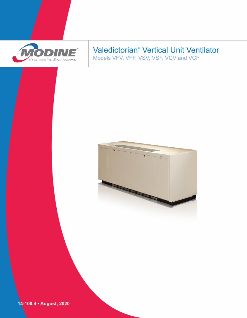
Valedictorian® Vertical Unit Ventilator Models VFV, VFF, VSV, VSF, VCV and VCF
14-100.4 • August, 2020

2 14-100.4
Valedictorian®
Modine endeavors to ensure that the information contained in this document is correct and fairly stated, but none of the statements contained in this document are to be relied upon as a statement or representation of fact. Modine does not accept liability for any error or omission, or for any reliance placed on the information contained in this document.
The development of Modine products and services is continuous and therefore the information contained in this document may not be up to date. It is important to check the current position of Modine at the address shown at the end of this document. This document is not part of a contract or license save insofar as may be expressly agreed.
No part of this document may be reproduced or transmitted in any form or by any means, electronic or mechanical, including photocopying, recording, of informational storage and retrieval systems, for any purpose other than the purchaser’s personal use, without the expressed written permission of Modine.
© 2020 Modine. All rights reserved. Printed in the USA.
INTRODUCTION
Modine is located in Racine, Wisconsin, and is one of the world’s leading manufacturers of heat pump and air conditioning systems for schools. Our reputation for product excellence has been earned through innovative design, our use of the highest quality controls, engineering selections of component parts, and the highest quality manufacturing and assembly of all products.
State-of-the-art test facilities reflect Modine’s commitment to the latest design and manufacturing technology to maintain leadership in the production of systems of unsurpassed quality and reliability.
In addition to creating a healthier and safer learning environment for our children, many of the features in Modine products are unique and the range of systems available offer schools a variety of options.
MODINE HAS A CONTINUOUS PRODUCT IMPROVEMENT PROGRAM AND THEREFORE RESERVES THE RIGHT TO CHANGE DESIGN AND SPECIFICATIONS WITHOUT NOTICE.
Table of Contents
Model Identification. . . . . . . . . . . . . . . . . . . . . . . . . . . . . . . . . . 3
Standard Features . . . . . . . . . . . . . . . . . . . . . . . . . . . . . . . . .4-5
Options / Accessories / Component Layout . . . . . . . . . . . . . .6-7
Supply Air Arrangement . . . . . . . . . . . . . . . . . . . . . . . . . . . . . . 8
Performance Data . . . . . . . . . . . . . . . . . . . . . . . . . . . . . . . .9-13
Technical Data . . . . . . . . . . . . . . . . . . . . . . . . . . . . . . . . . . . . 14
Dimensional Data
Inlet Air Arrangements . . . . . . . . . . . . . . . . . . . . . . . . .15-17
Floor Mounted Units . . . . . . . . . . . . . . . . . . . . . . . . . .18-21
Ceiling Mounted Units . . . . . . . . . . . . . . . . . . . . . . . . .22-23
Side Panels . . . . . . . . . . . . . . . . . . . . . . . . . . . . . . . . .24-25
Utility Compartments . . . . . . . . . . . . . . . . . . . . . . . . . . . . 26
Filler Sections / Unit Sub-Base . . . . . . . . . . . . . . . . . . . . 27
Duct Flange / Wall Sleeve / Louver . . . . . . . . . . . . . . . . . 28
Piping Components . . . . . . . . . . . . . . . . . . . . . . . . . . . . . . . . 29
Piping Locations
Standard Units . . . . . . . . . . . . . . . . . . . . . . . . . . . . . . .30-33
Units with Piping Package . . . . . . . . . . . . . . . . . . . . . .34-37
Outdoor Condensing Unit . . . . . . . . . . . . . . . . . . . . . . . . . .38-39
OverviewThe supplied product has been designed to be tough, dependable, aesthetically pleasing, quiet, and easy to install. The unit is built with heavy duty construction and incorporates a draw-through design. The unit is able to be configured for direct expansion (DX) cooling, chilled water, hot water, steam, or a combination of both chilled and hot water (two pipe and four pipe configurations), chilled water and steam, DX and hot water, or DX and steam. Discharge temrpeature is controlled using either a face-and-bypass damper or modulating control valve. Available adapter backs in various configurations allow for easy upgrades to existing systems, and optional factory installed controls have been engineered to ease installation. All access and maintenance shall be through the front of the unit.
The unit shall be constructed in accordance with UL & CSA standards with a label affixed to the unit listing the product code under which it is registered. Unit performance shall be tested in accordance with AHRI 840.
314-100.4
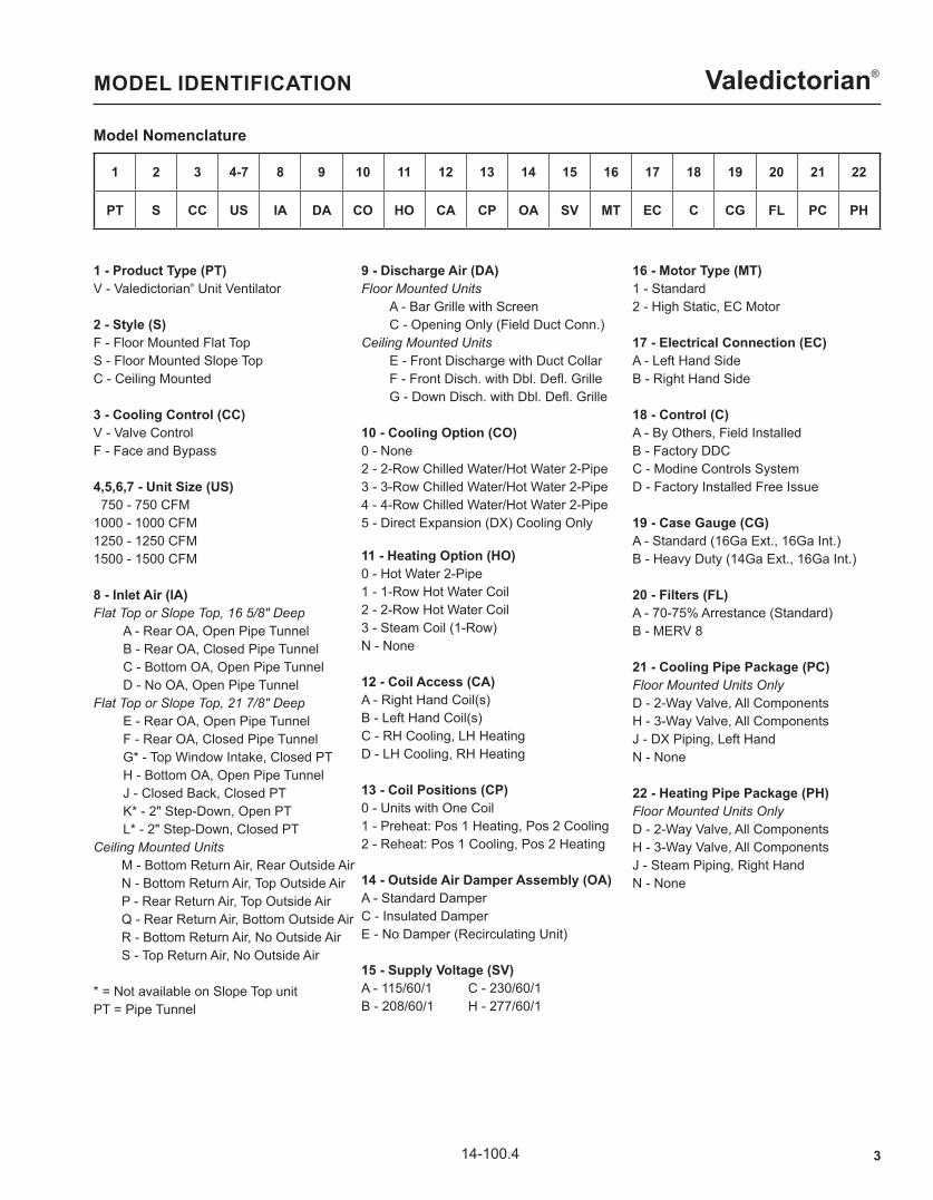
Valedictorian®MODEL IDENTIFICATION
Model Nomenclature
1 - Product Type (PT)V - Valedictorian® Unit Ventilator 2 - Style (S)F - Floor Mounted Flat TopS - Floor Mounted Slope TopC - Ceiling Mounted 3 - Cooling Control (CC)V - Valve ControlF - Face and Bypass 4,5,6,7 - Unit Size (US) 750 - 750 CFM1000 - 1000 CFM1250 - 1250 CFM1500 - 1500 CFM 8 - Inlet Air (IA)Flat Top or Slope Top, 16 5/8" Deep A - Rear OA, Open Pipe Tunnel B - Rear OA, Closed Pipe Tunnel C - Bottom OA, Open Pipe Tunnel D - No OA, Open Pipe TunnelFlat Top or Slope Top, 21 7/8" Deep E - Rear OA, Open Pipe Tunnel F - Rear OA, Closed Pipe Tunnel G* - Top Window Intake, Closed PT H - Bottom OA, Open Pipe Tunnel J - Closed Back, Closed PT K* - 2" Step-Down, Open PT L* - 2" Step-Down, Closed PTCeiling Mounted Units M - Bottom Return Air, Rear Outside Air N - Bottom Return Air, Top Outside Air P - Rear Return Air, Top Outside Air Q - Rear Return Air, Bottom Outside Air R - Bottom Return Air, No Outside Air S - Top Return Air, No Outside Air
* = Not available on Slope Top unitPT = Pipe Tunnel
9 - Discharge Air (DA)Floor Mounted Units A - Bar Grille with Screen C - Opening Only (Field Duct Conn.)Ceiling Mounted Units E - Front Discharge with Duct Collar F - Front Disch. with Dbl. Defl. Grille G - Down Disch. with Dbl. Defl. Grille
10 - Cooling Option (CO)0 - None2 - 2-Row Chilled Water/Hot Water 2-Pipe3 - 3-Row Chilled Water/Hot Water 2-Pipe4 - 4-Row Chilled Water/Hot Water 2-Pipe5 - Direct Expansion (DX) Cooling Only 11 - Heating Option (HO)0 - Hot Water 2-Pipe1 - 1-Row Hot Water Coil2 - 2-Row Hot Water Coil3 - Steam Coil (1-Row)N - None 12 - Coil Access (CA)A - Right Hand Coil(s)B - Left Hand Coil(s)C - RH Cooling, LH HeatingD - LH Cooling, RH Heating
13 - Coil Positions (CP)0 - Units with One Coil1 - Preheat: Pos 1 Heating, Pos 2 Cooling2 - Reheat: Pos 1 Cooling, Pos 2 Heating
14 - Outside Air Damper Assembly (OA)A - Standard DamperC - Insulated DamperE - No Damper (Recirculating Unit)
15 - Supply Voltage (SV)A - 115/60/1 C - 230/60/1B - 208/60/1 H - 277/60/1
16 - Motor Type (MT)1 - Standard2 - High Static, EC Motor
17 - Electrical Connection (EC)A - Left Hand SideB - Right Hand Side
18 - Control (C)A - By Others, Field InstalledB - Factory DDCC - Modine Controls SystemD - Factory Installed Free Issue
19 - Case Gauge (CG)A - Standard (16Ga Ext., 16Ga Int.)B - Heavy Duty (14Ga Ext., 16Ga Int.)
20 - Filters (FL)A - 70-75% Arrestance (Standard)B - MERV 8
21 - Cooling Pipe Package (PC)Floor Mounted Units OnlyD - 2-Way Valve, All ComponentsH - 3-Way Valve, All ComponentsJ - DX Piping, Left HandN - None
22 - Heating Pipe Package (PH)Floor Mounted Units OnlyD - 2-Way Valve, All ComponentsH - 3-Way Valve, All ComponentsJ - Steam Piping, Right HandN - None
1 2 3 4-7 8 9 10 11 12 13 14 15 16 17 18 19 20 21 22
PT S CC US IA DA CO HO CA CP OA SV MT EC C CG FL PC PH
4 14-100.4
Valedictorian®STANDARD FEATURES
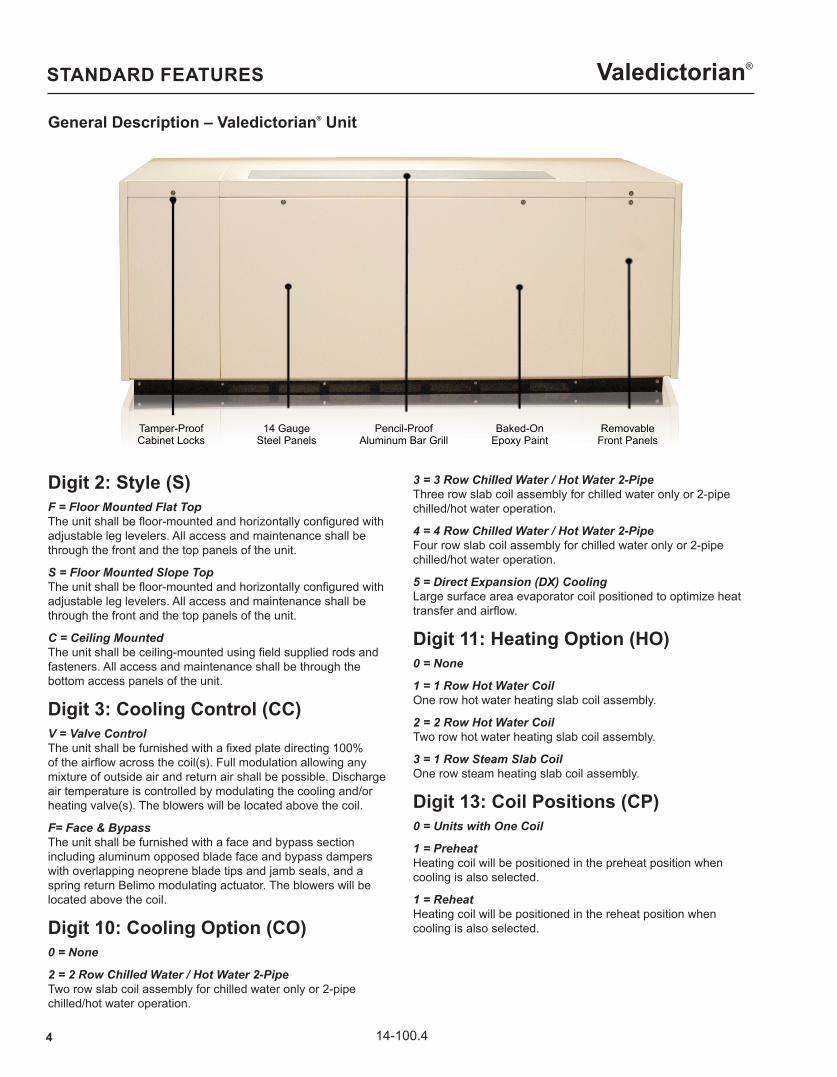
General Description – Valedictorian® Unit
Digit 2: Style (S)F = Floor Mounted Flat Top The unit shall be floor-mounted and horizontally configured with adjustable leg levelers. All access and maintenance shall be through the front and the top panels of the unit.
S = Floor Mounted Slope Top The unit shall be floor-mounted and horizontally configured with adjustable leg levelers. All access and maintenance shall be through the front and the top panels of the unit.
C = Ceiling Mounted The unit shall be ceiling-mounted using field supplied rods and fasteners. All access and maintenance shall be through the bottom access panels of the unit.
Digit 3: Cooling Control (CC)V = Valve Control The unit shall be furnished with a fixed plate directing 100% of the airflow across the coil(s). Full modulation allowing any mixture of outside air and return air shall be possible. Discharge air temperature is controlled by modulating the cooling and/or heating valve(s). The blowers will be located above the coil.
F= Face & Bypass The unit shall be furnished with a face and bypass section including aluminum opposed blade face and bypass dampers with overlapping neoprene blade tips and jamb seals, and a spring return Belimo modulating actuator. The blowers will be located above the coil.
Digit 10: Cooling Option (CO)0 = None
2 = 2 Row Chilled Water / Hot Water 2-Pipe Two row slab coil assembly for chilled water only or 2-pipe chilled/hot water operation.
3 = 3 Row Chilled Water / Hot Water 2-Pipe Three row slab coil assembly for chilled water only or 2-pipe chilled/hot water operation.
4 = 4 Row Chilled Water / Hot Water 2-Pipe Four row slab coil assembly for chilled water only or 2-pipe chilled/hot water operation.
5 = Direct Expansion (DX) Cooling Large surface area evaporator coil positioned to optimize heat transfer and airflow.
Digit 11: Heating Option (HO)0 = None
1 = 1 Row Hot Water Coil One row hot water heating slab coil assembly.
2 = 2 Row Hot Water Coil Two row hot water heating slab coil assembly.
3 = 1 Row Steam Slab Coil One row steam heating slab coil assembly.
Digit 13: Coil Positions (CP)0 = Units with One Coil
1 = Preheat Heating coil will be positioned in the preheat position when cooling is also selected.
1 = Reheat Heating coil will be positioned in the reheat position when cooling is also selected.
Tamper-ProofCabinet Locks
14 GaugeSteel Panels
Pencil-ProofAluminum Bar Grill
Baked-OnEpoxy Paint
RemovableFront Panels
514-100.4
Valedictorian®
Digit 21: Cooling Pipe Package (PC)D = 2-Way Valve, All Components Factory assembled and installed piping package including a 2-way valve, strainer, circuit setter, shut-off valves and PT ports.
H = 3-Way Valve, All Components Factory assembled and installed piping package including a 3-way valve, balancing valve, strainer, circuit setter, shut-off valves and PT ports.
J = DX Piping, Left Hand Refrigerant piping routed to left side of unit when the unit is equipped with a heating pipe package and left hand cooling terminations.
N = None
Digit 22: Heating Pipe Package (PH)D = 2-Way Valve, All Components Factory assembled and installed piping package including a 2-way valve, strainer, circuit setter, shut-off valves and PT ports.
H = 3-Way Valve, All Components Factory assembled and installed piping package including a 3-way valve, balancing valve, strainer, circuit setter, shut-off valves and PT ports.
J = Steam Piping, Right Hand Steam piping routed to right side of unit when the unit is equipped with a cooling pipe package and right hand heating terminations. Not available for Face & Bypass units.
N = None
Standard FeaturesCabinet Prior to assembly, the cabinet parts shall be degreased and coated with an electrostatically applied baked-on polyester powder paint and is insulated with acoustic foam containing no fibrous materials. The foam insulation shall have a fire rating of UL94 HF1.
The exterior panels of the cabinet shall be constructed of 16 gauge sheet metal. Internal sheet metal shall be galvanized 18 gauge. Heavy duty 14 gauge exterior panels are optional.
The front panel and compartment panels shall be easily removable with tamper-proof fasteners securing it to the rest of the unit cabinet. The back of the cabinet shall have an opening for connection to a wall sleeve and louver.
Control Panel The control panel is located in the left-hand compartment. All components located in the panel shall be clearly marked for easy identification. All terminal blocks and wire shall be individually numbered. All electrical wires in the control panel shall be run in an enclosed trough. Wiring outside of the control panel shall be run in protective sleeves.
The unit will be provided with a power disconnect sized for the full load amperage of the unit to enable the unit to be disconnected from the power supply prior to any maintenance.
The 3-speed selector switch enables adjustment of the supply air volume. Reduction in fan speed shall be achieved by a step down multi-tap transformer.
STANDARD FEATURES
Digit 14: Damper Assembly (OA)A = Standard Damper
B = Insulated Damper The outside air damper is insulated with 1/2" thick insulation to inhibit condensation on the damper surface.
E = No Damper (Recirculating Unit)
Digit 18: Control (C)A = By Others - Field Installed The unit will be provided without a controller or temperature sensors. The controller provided by others will be required to operate in a similar fashion to the Modine Control System (same inputs and outputs will be required). The controls contractor will be responsible for appropriate sequence of operations. A wiring diagram will be installed within the unit but will reflect a generic controller.
B = DDC Ready Controls The unit is provided with a fan relay, disconnect switch, three speed switch, 24-volt control circuit transformer and terminal strip. All components located in the panel shall be clearly marked for easy identification. All terminal blocks and wires shall be individually numbered. The controls contractor will be responsible for appropriate sequence of operations. A wiring diagram will be installed within the unit but will reflect a generic controller.
C = Modine Control System The unit is provided with the manufacturer's programmable microprocessor controller mounted outside of the air stream in the control panel. The controller is designed specifically for operating the unit in its most energy efficient manner using pre-engineered control strategies. The microprocessor determines mode of operation based on the factory installed return air, supply air, and outside air temperature sensors.
D = Factory Installed Free Issue The unit is provided with a controller and temperature sensors that have been provided by others. The controller provided by others will be required to operate in a similar fashion to the Modine Control System (same inputs and outputs will be required). Modine will provide coordination with the controls contractor. The controls contractor will be responsible for appropriate sequence of operations. A wiring diagram agreed upon by Modine and the Controls Contractor will be required before the units can be released for production.
Digit 20: Filtration (FL)A = 70-75% Arrestance (Standard) 1" thick throwaway filter provided and installed at the factory and located to provide filtration of both outdoor and return air prior to being conditioned.
B = MERV 8 1" thick radial pleated disposable filters provided and installed at the factory and located to provide filtration of both outdoor and return air prior to being conditioned.
Minimum Efficiency Reporting Value (MERV) corresponding to the MERV value shown below when evaluated per ASHRAE standard 52.2. Arrestance and Dust Spot Efficiency ratings are based on the ASHRAE 52.2 - 1992 test method.

6 14-100.4
Valedictorian®STANDARD FEATURES / OPTIONS / ACCESSORIES
Water / Steam Coils Large surface area slab coils for optimal heat transfer and airflow.
Evaporator All direct expansion units include a factory installed thermal expansion valve and utilize large surface area evaporator coils ideally positioned to optimize heat transfer and airflow. Each evaporator is manufactured from refrigeration quality copper tubes with mechanically bonded aluminum fins. Evaporator coils include a factory installed low limit stat.
Drain Pan Each unit shall be fitted with a 20 gauge, 304 stainless steel welded construction drain pan sloped in 3 directions. The condensate drain pan connection will be located on the same side as the cooling coil connection and include a 3/4" reinforced condensate tubing and spashguard over the drain port.
Supply Fan & Fan Motor Supply airflow is provided by a double inlet, forword curved, centrifugal type fan with offset aerodynamic blades. The assembly shall be statically and dynamically balanced to ensure smooth running and minimum noise levels. The fan motor is a permanent split capacitor type complete with intetgral automatic thermal overload protection. The fan and motor assembly shall be direct drive type with motor and bearings positioned outside of the airstream.
The fan assembly shall be possiitoned for a "draw through" configuration.
Factory Mounted OptionsBACnet Network Card The factory Microprocessor Control includes a plug-in card allowing for complete compatibility with an MS/TP BACnet control system.
LonWorks Network Card The factory Microprocessor Control includes a plug-in card allowing for complete compatibility with FT-10 LonWorks control system.
Time / Clock Card A time clock (card) shall be provided for "stand-alone" units where time functions, night and weekend setback, etc. are not transmitted from a building management system or remote central time clock. The time clock shall have a full 7 day schedule and calendar function incorporated. The 7 day schedule shall have two adjustable occupied/unoccupied periods per day. The calendar function shall allow 20 calendar periods (start date / stop date = 1 period).
Display Module The user interface for Modine Control System displays status of controllers inputs and outputs, allows for occupied/unoccupied setpoint changes, displays servce settings, allows adjustment of control parameters, and is used for troubleshooting the unit. (This is required to change any factory setpoints if it is not receiving a signal from a BMS system).
Coil Freeze Protection An automatic reset freeze protection bulb and capillary tube mounted on the discharge side of the first coil to prevent any freezing of the first coil assembly. When the sensor detects a freeze up condition it will force the damper to close off the
outside air, force the flow control valve open and prevent theunit supply fan from running.
CO2 Sensor The CO2 sensor shall be field mounted in the interior return air passage of the unit or remotely mounted to provide demand ventilation. When the level of CO2 rises over a predetermined set point, the sensor shall proportionally adjust the minimum damper position to allow larger quantities of outside air into the room. The sensor shall have the capability of measuring CO2 levels from 0 to 2,000 ppm with an accuracy of +/- 40 ppm CO2 +3.0% of the reading.
Aquastat An aquastat shall be fitted to two pipe systems to prevent changeover into a heating mode when cooling is required and vice-versa.
Condensate Pump The unit shall be fitted with a condensate pump. The pump shall be equipped with an ABS plastic tank with built-in flow check valve and safety switch.
Condensate Pan Float Switch The unit shall be fitted with a float switch mounted on the condensate pan to stop the cooling function should the condensate rise to a predetermined level.
Insulated Damper Assembly 1/2" thick insulation shall be added to the damper assembly to inhibit condensation on the damper surface.
EC Motor The electronically commutated motor (ECM) provides constant airflow by automatically adjusting the speed if the external static pressure changes. The DC motor features a brushless, permanently lubricated ball bearing construction for maintenance free operation. The ECM is fully programmed to compensate for a wide variety of static pressures as well as lack of maintenance (dirty air filters).
Factory Assembled Valve Package The selected piping components can be factory assembled, with all necessary piping and unions, and shipped fully supported and connected to the coil(s) with piping routed to selected Coil Access side. The valve package can include factory piped circuit setter and strainer (when selected, if applicable).
Field Installed AccessoriesRoom Sensor with Offset and Override For units fitted with the Modine Control System, a stainless steel flush-mount thermistor sensor with insulated back provides for +/- 3O setpoint adjustment and momentary push button override. Sensor is wall mounted remote from the unit.
Digital Wallstat Digital thermostat used in conjuction with the Modine Control System displays current room temperature, cooling/heating setpoint, and current occupied mode. The display will also display a remote alarm from the Microprocessor Control. Thermostat allows for occupied temperature setpoint adjustment. The allowable setpoint adjustment range can be limited by the Microprocessor Control. Thermostat allows for occupied override activation allowing user to select the amount of time the unit is to remain in the override state. Thermostat is wall mounted remote from the unit.
714-100.4
Valedictorian®
Modulating Control Valve Two-way or three-way modulating valve(s) shall be provided for precise capacity control of hot water and/or chilled water coil(s). The capacity control valve(s) shall be controled by a 2-10VDC or floating point signal from the unit mounted controller and shipped loose for field installation.
2-Position Spring Return Control Valve Two-way or three-way 2-position spring return control valve(s) shall be provided for control of hot water and/or chilled water coil(s). The control valve(s) shall be controlled by a 24V signal from the units control panel and shipped loose for field installation.
Balancing Valve A heavy duty ball-valve contruction balancing valve shall be supplied loose for field installation.
Circuit Setter A manually adjustable ball-valve contruction balancing valve with Schrader style pressure ports and drain port shall be supplied loose for field installation.
Shut-Off Valves A set of two heavy duty ball valves, one for the supply and one for the return, shall be supplied loose for field installation.
Strainer A heavy duty cast iron strainer with screen, gasketed and tapped retainer cap and blow-off outlet shall be supplied loose for field installation.
Drain with Hose Bib A blowdown valve with hose connector and cap shall be mounted on the coil.
Side Panels Factory supplied side panels constructed of 14 or 16 gauge sheet steel and painted to match the unit shall be field mounted to the base unit. Side panels are available for both 16 5/8" and 21 7/8" deep units with or without pipe passage cutouts.
Utility Compartment A factory supplied utility compartment with 14 gauge sheet steel front and top panels and painted to match the unit shall be field mounted to the base unit. Utility compartments are available for both 16 5/8" and 21 7/8" deep units in 12", 18" and 24" widths.
Filler Section A factory supplied filler section constructed of 18 gauge sheet steel and painted to match the unit shall be field mounted. Filler sections are available in 6", 12" and 18" widths and can be field cut for custom widths.
Unit Sub-Base Unit height adjustments can be made in increments of 1", 2", 4" and 6" with a sub-base field mounted under the standard unit. The sub-base is fully enclosed, constructed of heavy duty steel and painted to match the base of the standard unit.
Utility Compartment Sub-Base Utility compartment height adjustments can be made in increments of 1", 2", 4" and 6" with a sub-base field mounted under the standard utility compartment. The sub-base is fully enclosed, constructed of heavy duty steel and painted to match the base of the standard utility compartment.
Wall Sleeve The wall sleeve shall be constructed from galvanized steel. The sleeve shall be provided by Modine and insulated by the installing contractor with foil back insulation.
Louver An outdoor louver shall be furnished by Modine and be suitable for masonry, glass or panel wall ocnstruction. Two louver styles are available: AMCA rated and non-AMCA rated. Louvers shall be availabe in the following materials: • Aluminum with clear anodized finish • Aluminum with baked enamel finish, customer selected from manufacturer's standard louver color chart
Duct Flange A 1" duct flange shall be supplied and field installed to allow for easy installation of a supply air duct to the unit.
ACCESSORIES / COMPONENT LAYOUT
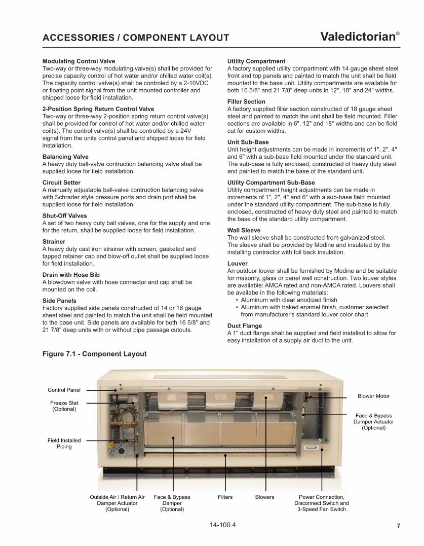
Figure 7.1 - Component Layout
Control PanelBlower Motor
Freeze Stat(Optional)
Face & Bypass Damper Actuator
(Optional)
Field Installed Piping
Outside Air / Return Air Damper Actuator
(Optional)
Face & BypassDamper
(Optional)
Filters Blowers Power Connection,Disconnect Switch and3-Speed Fan Switch
8 14-100.4
Valedictorian®SUPPLY AIR ARRANGEMENT
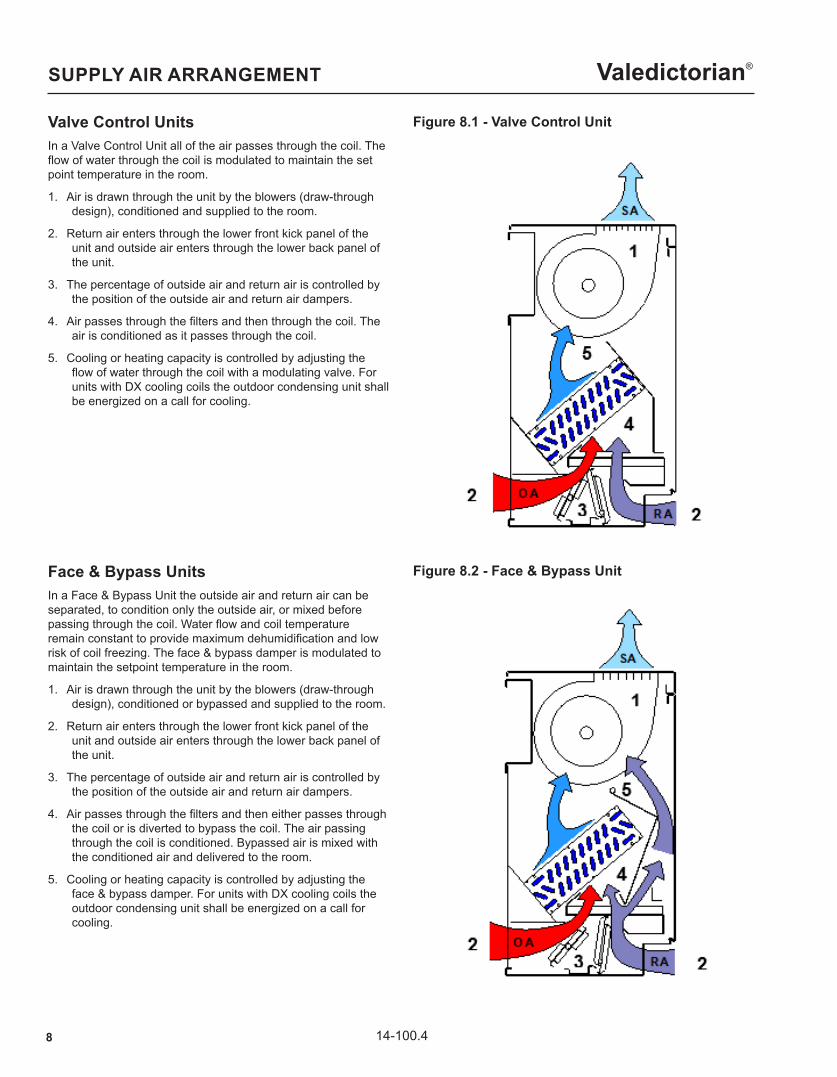
Figure 8.1 - Valve Control Unit
Figure 8.2 - Face & Bypass Unit
Valve Control UnitsIn a Valve Control Unit all of the air passes through the coil. The flow of water through the coil is modulated to maintain the set point temperature in the room.
1. Air is drawn through the unit by the blowers (draw-through design), conditioned and supplied to the room.
2. Return air enters through the lower front kick panel of the unit and outside air enters through the lower back panel of the unit.
3. The percentage of outside air and return air is controlled by the position of the outside air and return air dampers.
4. Air passes through the filters and then through the coil. The air is conditioned as it passes through the coil.
5. Cooling or heating capacity is controlled by adjusting the flow of water through the coil with a modulating valve. For units with DX cooling coils the outdoor condensing unit shall be energized on a call for cooling.
Face & Bypass UnitsIn a Face & Bypass Unit the outside air and return air can be separated, to condition only the outside air, or mixed before passing through the coil. Water flow and coil temperature remain constant to provide maximum dehumidification and low risk of coil freezing. The face & bypass damper is modulated to maintain the setpoint temperature in the room.
1. Air is drawn through the unit by the blowers (draw-through design), conditioned or bypassed and supplied to the room.
2. Return air enters through the lower front kick panel of the unit and outside air enters through the lower back panel of the unit.
3. The percentage of outside air and return air is controlled by the position of the outside air and return air dampers.
4. Air passes through the filters and then either passes through the coil or is diverted to bypass the coil. The air passing through the coil is conditioned. Bypassed air is mixed with the conditioned air and delivered to the room.
5. Cooling or heating capacity is controlled by adjusting the face & bypass damper. For units with DX cooling coils the outdoor condensing unit shall be energized on a call for cooling.

914-100.4
Valedictorian®PERFORMANCE DATA
Table 9.1 - Unit Size 750 & 1000 Chilled Water Performance Data
EWT(OF)
FlowRate
(GPM)Numberof Rows
750 1000
PD (ft) CapacityType
Airflow CFMPD (ft) Capacity
TypeAirflow CFM
High Medium Low High Medium Low
45
6
2 2.09Total 18,312 17,071 14,694
2.58Total 27,859 24,376 21,468
Sensible 14,965 13,694 11,464 Sensible 22,876 19,163 16,439
3 1.03Total 26,160 24,388 20,991
1.29Total 32,775 28,678 25,256
Sensible 18,707 17,118 14,330 Sensible 24,080 20,172 17,304
4 1.14Total 27,520 25,656 22,083
1.35Total 34,454 30,147 26,550
Sensible 19,109 17,486 14,639 Sensible 24,461 20,490 17,578
10
2 5.20Total 21,297 19,255 16,392
6.40Total 32,099 28,494 25,835
Sensible 16,533 14,908 12,508 Sensible 25,955 21,442 19,026
3 2.57Total 30,424 27,508 23,417
3.20Total 37,763 33,523 30,394
Sensible 20,665 18,635 15,635 Sensible 27,321 22,571 20,028
4 2.84Total 32,066 28,938 24,634
3.35Total 39,698 35,240 31,951
Sensible 21,110 19,036 15,971 Sensible 27,752 22,927 20,344 j Cooling Capacity based on Air On 80/67OF Dry/Web Bulb. k For additional capacity information, please consult Breeze AccuSpec.
Table 9.2 - Unit Size 1250 & 1500 Chilled Water Performance Data
EWT(OF)
FlowRate
(GPM)Numberof Rows
1250 1500
PD (ft) CapacityType
Airflow CFMPD (ft) Capacity
TypeAirflow CFM
High Medium Low High Medium Low
45
6
2 3.40Total 32,871 28,391 25,135
3.10Total 37,455 32,871 29,721
Sensible 27,608 22,624 19,635 Sensible 32,186 26,797 23,503
3 1.68Total 38,671 33,401 29,571
1.77Total 44,064 38,672 34,966
Sensible 29,061 23,814 20,668 Sensible 33,880 28,207 24,740
4 1.38Total 40,652 35,112 31,085
1.26Total 49,356 40,683 36,784
Sensible 29,520 24,191 20,995 Sensible 34,601 28,808 25,267
10
2 8.30Total 39,623 32,737 29,067
7.55Total 45,709 38,736 34,125
Sensible 30,868 24,748 21,672 Sensible 36,205 29,616 25,637
3 4.09Total 46,616 38,514 34,197
4.21Total 53,775 45,572 40,147
Sensible 32,493 26,050 22,813 Sensible 38,111 31,175 26,987
4 3.43Total 49,004 40,487 35,949
3.07Total 56,572 47,942 42,235
Sensible 33,006 26,462 23,173 Sensible 38,922 31,839 27,562 j Cooling Capacity based on Air On 80/67OF Dry/Web Bulb. k For additional capacity information, please consult Breeze AccuSpec.
10 14-100.4
Valedictorian®PERFORMANCE DATA
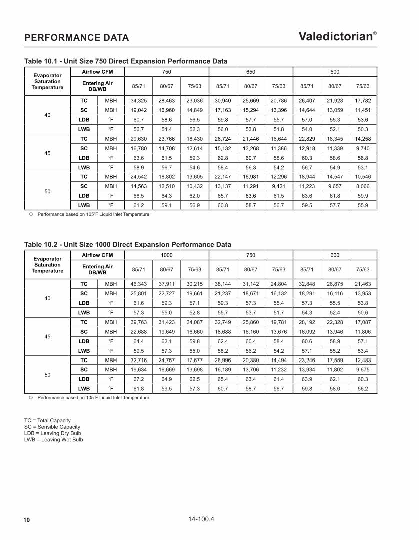
Table 10.1 - Unit Size 750 Direct Expansion Performance Data
EvaporatorSaturation
Temperature
Airflow CFM 750 650 500
Entering AirDB/WB 85/71 80/67 75/63 85/71 80/67 75/63 85/71 80/67 75/63
40
TC MBH 34,325 28,463 23,036 30,940 25,669 20,786 26,407 21,928 17,782
SC MBH 19,042 16,960 14,849 17,163 15,294 13,396 14,644 13,059 11,451
LDB OF 60.7 58.6 56.5 59.8 57.7 55.7 57.0 55.3 53.6
LWB OF 56.7 54.4 52.3 56.0 53.8 51.8 54.0 52.1 50.3
45
TC MBH 29,630 23,766 18,430 26,724 21,446 16,644 22,829 18,345 14,258
SC MBH 16,780 14,708 12,614 15,132 13,268 11,386 12,918 11,339 9,740
LDB OF 63.6 61.5 59.3 62.8 60.7 58.6 60.3 58.6 56.8
LWB OF 58.9 56.7 54.6 58.4 56.3 54.2 56.7 54.9 53.1
50
TC MBH 24,542 18,802 13,605 22,147 16,981 12,296 18,944 14,547 10,546
SC MBH 14,563 12,510 10,432 13,137 11,291 9,421 11,223 9,657 8,066
LDB OF 66.5 64.3 62.0 65.7 63.6 61.5 63.6 61.8 59.9
LWB OF 61.2 59.1 56.9 60.8 58.7 56.7 59.5 57.7 55.9 j Performance based on 105OF Liquid Inlet Temperature.
Table 10.2 - Unit Size 1000 Direct Expansion Performance Data
j Performance based on 105OF Liquid Inlet Temperature.
TC = Total Capacity SC = Sensible Capacity LDB = Leaving Dry Bulb LWB = Leaving Wet Bulb
EvaporatorSaturation
Temperature
Airflow CFM 1000 750 600
Entering AirDB/WB 85/71 80/67 75/63 85/71 80/67 75/63 85/71 80/67 75/63
40
TC MBH 46,343 37,911 30,215 38,144 31,142 24,804 32,848 26,875 21,463
SC MBH 25,801 22,727 19,661 21,237 18,671 16,132 18,291 16,116 13,953
LDB OF 61.6 59.3 57.1 59.3 57.3 55.4 57.3 55.5 53.8
LWB OF 57.3 55.0 52.8 55.7 53.7 51.7 54.3 52.4 50.6
45
TC MBH 39,763 31,423 24,087 32,749 25,860 19,781 28,192 22,328 17,087
SC MBH 22,688 19,649 16,660 18,688 16,160 13,676 16,092 13,946 11,806
LDB OF 64.4 62.1 59.8 62.4 60.4 58.4 60.6 58.9 57.1
LWB OF 59.5 57.3 55.0 58.2 56.2 54.2 57.1 55.2 53.4
50
TC MBH 32,716 24,757 17,677 26,996 20,380 14,494 23,246 17,559 12,483
SC MBH 19,634 16,669 13,698 16,189 13,706 11,232 13,934 11,802 9,675
LDB OF 67.2 64.9 62.5 65.4 63.4 61.4 63.9 62.1 60.3
LWB OF 61.8 59.5 57.3 60.7 58.7 56.7 59.8 58.0 56.2

1114-100.4
Valedictorian®PERFORMANCE DATA
Table 11.1 - Unit Size 1250 Direct Expansion Performance Data
Table 11.2 - Unit Size 1500 Direct Expansion Performance Data
j Performance based on 105OF Liquid Inlet Temperature.
j Performance based on 105OF Liquid Inlet Temperature.
TC = Total Capacity SC = Sensible Capacity LDB = Leaving Dry Bulb LWB = Leaving Wet Bulb
EvaporatorSaturation
Temperature
Airflow CFM 1250 900 750
Entering AirDB/WB 85/71 80/67 75/63 85/71 80/67 75/63 85/71 80/67 75/63
40
TC MBH 62,055 50,784 40,492 49,872 40,756 32,468 43,540 35,633 28,453
SC MBH 34,494 30,368 26,263 27,729 24,385 21,063 24,212 21,326 18,455
LDB OF 59.9 57.9 55.9 57.0 55.3 53.7 55.6 54.1 52.6
LWB OF 56.1 54.0 51.9 54.1 52.2 50.5 53.1 51.4 49.7
45
TC MBH 53,246 42,060 32,261 42,825 33,830 25,876 37,376 29,596 22,633
SC MBH 30,293 26,219 22,226 24,380 21,079 17,834 21,284 18,436 15,600
LDB OF 63.0 60.9 58.8 60.4 58.7 57.0 59.2 57.6 56.1
LWB OF 58.6 56.5 54.4 56.9 55.1 53.3 56.1 54.4 52.8
50
TC MBH 43,777 33,135 23,674 35,296 26,613 18,942 30,791 23,255 16,537
SC MBH 26,181 22,224 18,271 21,096 17,848 14,631 18,405 15,588 12,778
LDB OF 66.0 63.9 61.7 63.7 62.0 60.2 62.7 61.1 59.5
LWB OF 61.0 58.9 56.8 59.7 57.9 56.1 59.1 57.4 55.7
EvaporatorSaturation
Temperature
Airflow CFM 1500 1100 900
Entering AirDB/WB 85/71 80/67 75/63 85/71 80/67 75/63 85/71 80/67 75/63
40
TC MBH 71,293 58,404 46,636 57,981 47,427 37,803 50,287 41,211 32,891
SC MBH 39,581 34,844 30,138 32,198 28,311 24,452 27,930 24,610 21,290
LDB OF 61.0 58.9 56.7 58.4 56.6 54.7 56.8 55.1 53.4
LWB OF 56.9 54.6 52.4 55.1 53.1 51.2 53.9 52.0 50.3
45
TC MBH 61,240 48,405 37,142 49,855 39,329 30,174 43,229 34,188 26,276
SC MBH 34,743 30,066 25,490 28,303 24,455 20,712 24,552 21,257 18,037
LDB OF 64.0 61.8 59.5 61.6 59.8 57.9 60.2 58.5 56.7
LWB OF 59.2 57.0 54.8 57.6 55.7 53.8 56.7 54.9 53.1
50
TC MBH 50,283 38,162 27,273 41,040 31,073 22,195 35,610 27,006 19,326
SC MBH 29,992 25,478 20,972 24,471 20,749 17,051 21,229 18,034 14,838
LDB OF 66.9 64.6 62.3 64.8 62.9 60.9 63.6 61.8 60.0
LWB OF 61.5 59.3 57.1 60.3 58.3 56.4 59.6 57.7 55.9
12 14-100.4
Valedictorian®PERFORMANCE DATA
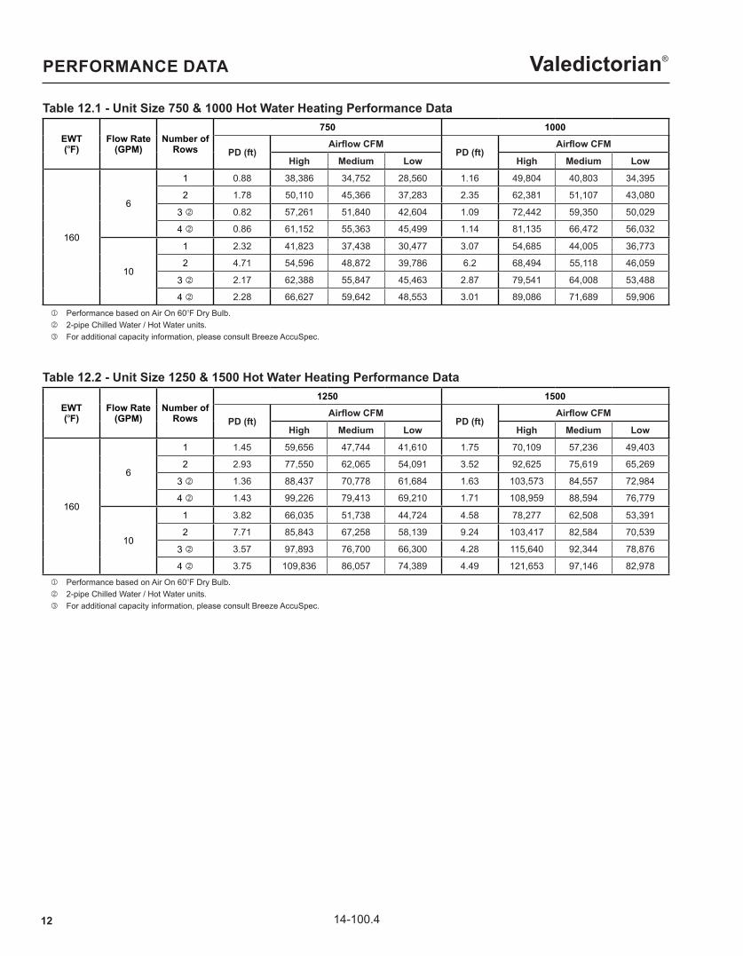
Table 12.1 - Unit Size 750 & 1000 Hot Water Heating Performance Data
EWT(OF)
Flow Rate(GPM)
Number of Rows
750 1000
PD (ft)Airflow CFM
PD (ft)Airflow CFM
High Medium Low High Medium Low
160
6
1 0.88 38,386 34,752 28,560 1.16 49,804 40,803 34,395
2 1.78 50,110 45,366 37,283 2.35 62,381 51,107 43,080
3 k 0.82 57,261 51,840 42,604 1.09 72,442 59,350 50,029
4 k 0.86 61,152 55,363 45,499 1.14 81,135 66,472 56,032
10
1 2.32 41,823 37,438 30,477 3.07 54,685 44,005 36,773
2 4.71 54,596 48,872 39,786 6.2 68,494 55,118 46,059
3 k 2.17 62,388 55,847 45,463 2.87 79,541 64,008 53,488
4 k 2.28 66,627 59,642 48,553 3.01 89,086 71,689 59,906 j Performance based on Air On 60OF Dry Bulb. k 2-pipe Chilled Water / Hot Water units. l For additional capacity information, please consult Breeze AccuSpec.
Table 12.2 - Unit Size 1250 & 1500 Hot Water Heating Performance Data
EWT(OF)
Flow Rate(GPM)
Number of Rows
1250 1500
PD (ft)Airflow CFM
PD (ft)Airflow CFM
High Medium Low High Medium Low
160
6
1 1.45 59,656 47,744 41,610 1.75 70,109 57,236 49,403
2 2.93 77,550 62,065 54,091 3.52 92,625 75,619 65,269
3 k 1.36 88,437 70,778 61,684 1.63 103,573 84,557 72,984
4 k 1.43 99,226 79,413 69,210 1.71 108,959 88,594 76,779
10
1 3.82 66,035 51,738 44,724 4.58 78,277 62,508 53,391
2 7.71 85,843 67,258 58,139 9.24 103,417 82,584 70,539
3 k 3.57 97,893 76,700 66,300 4.28 115,640 92,344 78,876
4 k 3.75 109,836 86,057 74,389 4.49 121,653 97,146 82,978 j Performance based on Air On 60OF Dry Bulb. k 2-pipe Chilled Water / Hot Water units. l For additional capacity information, please consult Breeze AccuSpec.
1314-100.4
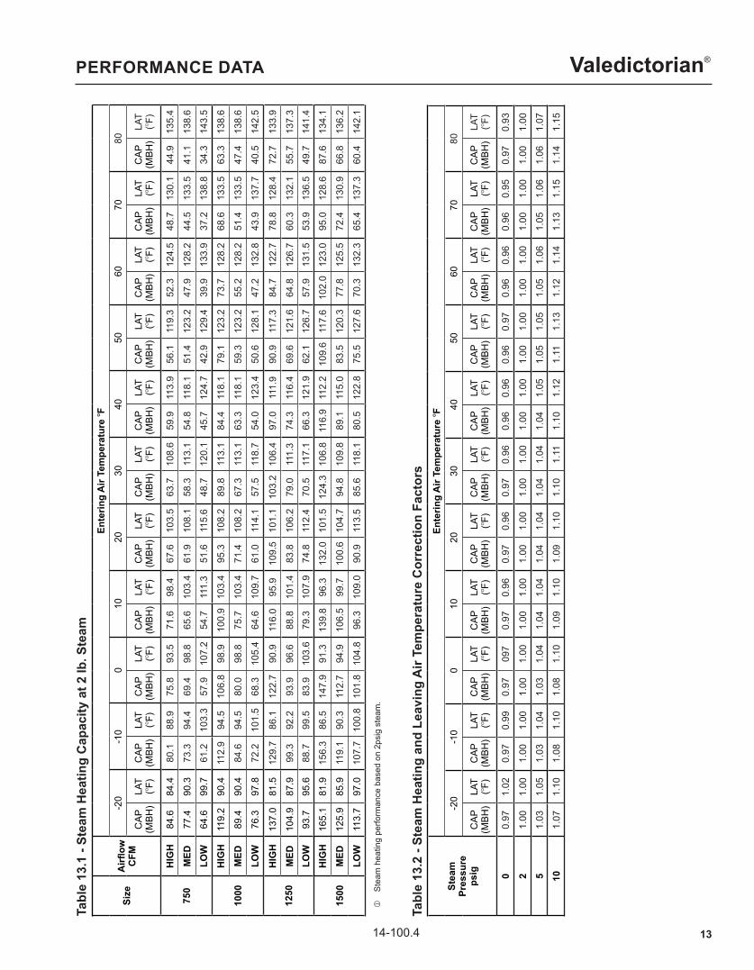
Valedictorian®PERFORMANCE DATATa
ble
13.1
- St
eam
Hea
ting
Cap
acity
at 2
lb. S
team
Size
Airfl
owC
FM
Ente
ring
Air
Tem
pera
ture
OF
-20
-10
010
2030
4050
6070
80
CAP
(MBH
)LA
T(O
F)C
AP(M
BH)
LAT
(OF)
CAP
(MBH
)LA
T(O
F)C
AP(M
BH)
LAT
(OF)
CAP
(MBH
)LA
T(O
F)C
AP(M
BH)
LAT
(OF)
CAP
(MBH
)LA
T(O
F)C
AP(M
BH)
LAT
(OF)
CAP
(MBH
)LA
T(O
F)C
AP(M
BH)
LAT
(OF)
CAP
(MBH
)LA
T(O
F)
750
HIG
H84
.684
.480
.188
.975
.893
.571
.698
.467
.610
3.5
63.7
108.
659
.911
3.9
56.1
119.
352
.312
4.5
48.7
130.
144
.913
5.4
MED
77.4
90.3
73.3
94.4
69.4
98.8
65.6
103.
461
.910
8.1
58.3
113.
154
.811
8.1
51.4
123.
247
.912
8.2
44.5
133.
541
.113
8.6
LOW
64.6
99.7
61.2
103.
357
.910
7.2
54.7
111.
351
.611
5.6
48.7
120.
145
.712
4.7
42.9
129.
439
.913
3.9
37.2
138.
834
.314
3.5
1000
HIG
H11
9.2
90.4
112.
994
.510
6.8
98.9
100.
910
3.4
95.3
108.
289
.811
3.1
84.4
118.
179
.112
3.2
73.7
128.
268
.613
3.5
63.3
138.
6
MED
89.4
90.4
84.6
94.5
80.0
98.8
75.7
103.
471
.410
8.2
67.3
113.
163
.311
8.1
59.3
123.
255
.212
8.2
51.4
133.
547
.413
8.6
LOW
76.3
97.8
72.2
101.
568
.310
5.4
64.6
109.
761
.011
4.1
57.5
118.
754
.012
3.4
50.6
128.
147
.213
2.8
43.9
137.
740
.514
2.5
1250
HIG
H13
7.0
81.5
129.
786
.112
2.7
90.9
116.
095
.910
9.5
101.
110
3.2
106.
497
.011
1.9
90.9
117.
384
.712
2.7
78.8
128.
472
.713
3.9
MED
104.
987
.999
.392
.293
.996
.688
.810
1.4
83.8
106.
279
.011
1.3
74.3
116.
469
.612
1.6
64.8
126.
760
.313
2.1
55.7
137.
3LO
W93
.795
.688
.799
.583
.910
3.6
79.3
107.
974
.811
2.4
70.5
117.
166
.312
1.9
62.1
126.
757
.913
1.5
53.9
136.
549
.714
1.4
1500
HIG
H16
5.1
81.9
156.
386
.514
7.9
91.3
139.
896
.313
2.0
101.
512
4.3
106.
811
6.9
112.
210
9.6
117.
610
2.0
123.
095
.012
8.6
87.6
134.
1
MED
125.
985
.911
9.1
90.3
112.
794
.910
6.5
99.7
100.
610
4.7
94.8
109.
889
.111
5.0
83.5
120.
377
.812
5.5
72.4
130.
966
.813
6.2
LOW
113.
797
.010
7.7
100.
810
1.8
104.
896
.310
9.0
90.9
113.
585
.611
8.1
80.5
122.
875
.512
7.6
70.3
132.
365
.413
7.3
60.4
142.
1
j
Stea
m h
eatin
g pe
rform
ance
bas
ed o
n 2p
sig
stea
m.
Tabl
e 13
.2 -
Stea
m H
eatin
g an
d Le
avin
g A
ir Te
mpe
ratu
re C
orre
ctio
n Fa
ctor
s
Stea
mPr
essu
reps
ig
Ente
ring
Air
Tem
pera
ture
OF
-20
-10
010
2030
4050
6070
80
CAP
(MBH
)LA
T(O
F)C
AP(M
BH)
LAT
(OF)
CAP
(MBH
)LA
T(O
F)C
AP(M
BH)
LAT
(OF)
CAP
(MBH
)LA
T(O
F)C
AP(M
BH)
LAT
(OF)
CAP
(MBH
)LA
T(O
F)C
AP(M
BH)
LAT
(OF)
CAP
(MBH
)LA
T(O
F)C
AP(M
BH)
LAT
(OF)
CAP
(MBH
)LA
T(O
F)
00.
971.
020.
970.
990.
9709
70.
970.
960.
970.
960.
970.
960.
960.
960.
960.
970.
960.
960.
960.
950.
970.
93
21.
001.
001.
001.
001.
001.
001.
001.
001.
001.
001.
001.
001.
001.
001.
001.
001.
001.
001.
001.
001.
001.
00
51.
031.
051.
031.
041.
031.
041.
041.
041.
041.
041.
041.
041.
041.
051.
051.
051.
051.
061.
051.
061.
061.
07
101.
071.
101.
081.
101.
081.
101.
091.
101.
091.
101.
101.
111.
101.
121.
111.
131.
121.
141.
131.
151.
141.
15
14 14-100.4
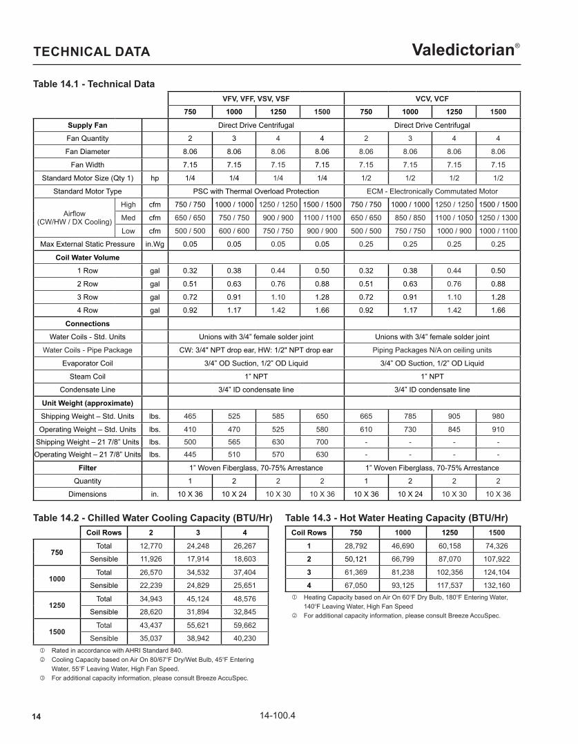
Valedictorian®TECHNICAL DATA
Table 14.1 - Technical DataVFV, VFF, VSV, VSF VCV, VCF
750 1000 1250 1500 750 1000 1250 1500
Supply Fan Direct Drive Centrifugal Direct Drive Centrifugal
Fan Quantity 2 3 4 4 2 3 4 4
Fan Diameter 8.06 8.06 8.06 8.06 8.06 8.06 8.06 8.06
Fan Width 7.15 7.15 7.15 7.15 7.15 7.15 7.15 7.15
Standard Motor Size (Qty 1) hp 1/4 1/4 1/4 1/4 1/2 1/2 1/2 1/2
Standard Motor Type PSC with Thermal Overload Protection ECM - Electronically Commutated Motor
Airflow(CW/HW / DX Cooling)
High cfm 750 / 750 1000 / 1000 1250 / 1250 1500 / 1500 750 / 750 1000 / 1000 1250 / 1250 1500 / 1500
Med cfm 650 / 650 750 / 750 900 / 900 1100 / 1100 650 / 650 850 / 850 1100 / 1050 1250 / 1300
Low cfm 500 / 500 600 / 600 750 / 750 900 / 900 500 / 500 750 / 750 1000 / 900 1000 / 1100
Max External Static Pressure in.Wg 0.05 0.05 0.05 0.05 0.25 0.25 0.25 0.25
Coil Water Volume1 Row gal 0.32 0.38 0.44 0.50 0.32 0.38 0.44 0.50
2 Row gal 0.51 0.63 0.76 0.88 0.51 0.63 0.76 0.88
3 Row gal 0.72 0.91 1.10 1.28 0.72 0.91 1.10 1.28
4 Row gal 0.92 1.17 1.42 1.66 0.92 1.17 1.42 1.66
ConnectionsWater Coils - Std. Units Unions with 3/4” female solder joint Unions with 3/4” female solder joint
Water Coils - Pipe Package CW: 3/4" NPT drop ear, HW: 1/2" NPT drop ear Piping Packages N/A on ceiling units
Evaporator Coil 3/4” OD Suction, 1/2” OD Liquid 3/4” OD Suction, 1/2” OD Liquid
Steam Coil 1” NPT 1” NPT
Condensate Line 3/4” ID condensate line 3/4” ID condensate line
Unit Weight (approximate)Shipping Weight – Std. Units lbs. 465 525 585 650 665 785 905 980
Operating Weight – Std. Units lbs. 410 470 525 580 610 730 845 910
Shipping Weight – 21 7/8” Units lbs. 500 565 630 700 - - - -Operating Weight – 21 7/8” Units lbs. 445 510 570 630 - - - -
Filter 1” Woven Fiberglass, 70-75% Arrestance 1” Woven Fiberglass, 70-75% Arrestance
Quantity 1 2 2 2 1 2 2 2
Dimensions in. 10 X 36 10 X 24 10 X 30 10 X 36 10 X 36 10 X 24 10 X 30 10 X 36
Table 14.2 - Chilled Water Cooling Capacity (BTU/Hr)Coil Rows 750 1000 1250 1500
1 28,792 46,690 60,158 74,326
2 50,121 66,799 87,070 107,922
3 61,369 81,238 102,356 124,104
4 67,050 93,125 117,537 132,160
Table 14.3 - Hot Water Heating Capacity (BTU/Hr)
j Rated in accordance with AHRI Standard 840. k Cooling Capacity based on Air On 80/67OF Dry/Wet Bulb, 45OF Entering j Water, 55OF Leaving Water, High Fan Speed. l For additional capacity information, please consult Breeze AccuSpec.
j Heating Capacity based on Air On 60OF Dry Bulb, 180OF Entering Water, j 140OF Leaving Water, High Fan Speed k For additional capacity information, please consult Breeze AccuSpec.
Coil Rows 2 3 4
750Total 12,770 24,248 26,267
Sensible 11,926 17,914 18,603
1000Total 26,570 34,532 37,404
Sensible 22,239 24,829 25,651
1250Total 34,943 45,124 48,576
Sensible 28,620 31,894 32,845
1500Total 43,437 55,621 59,662
Sensible 35,037 38,942 40,230
1514-100.4
Valedictorian®
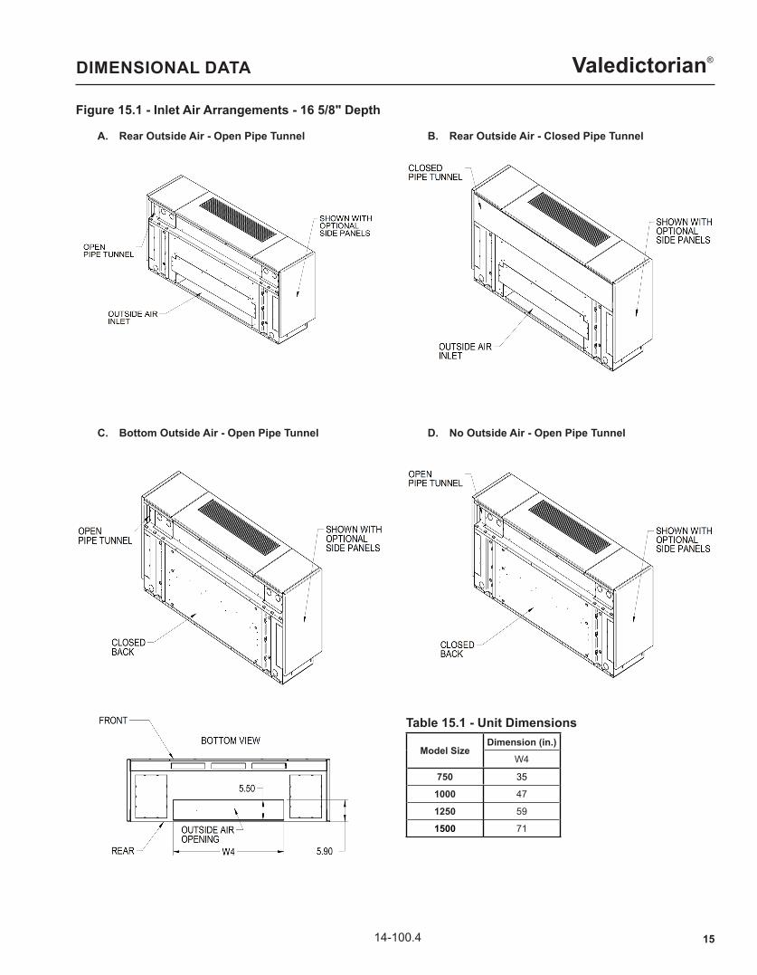
Figure 15.1 - Inlet Air Arrangements - 16 5/8" Depth
Model SizeDimension (in.)
W4
750 35
1000 47
1250 59
1500 71
Table 15.1 - Unit Dimensions
DIMENSIONAL DATA
A. Rear Outside Air - Open Pipe Tunnel B. Rear Outside Air - Closed Pipe Tunnel
C. Bottom Outside Air - Open Pipe Tunnel D. No Outside Air - Open Pipe Tunnel
16 14-100.4
Valedictorian®
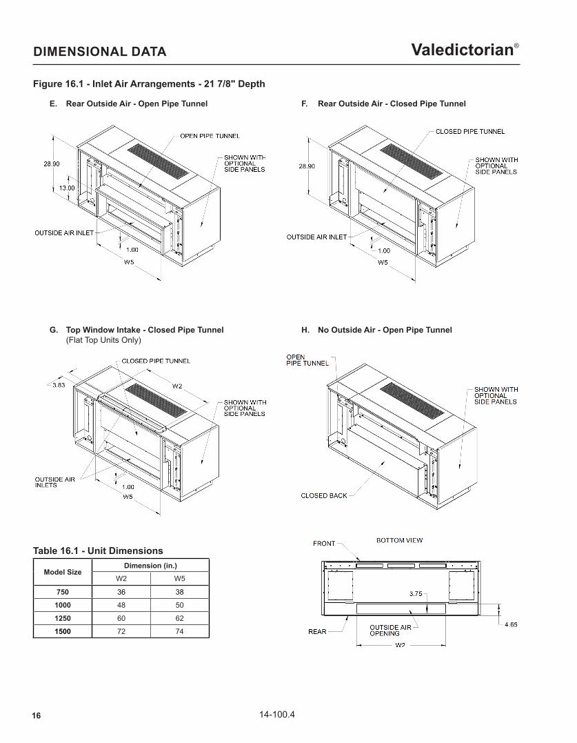
Figure 16.1 - Inlet Air Arrangements - 21 7/8" Depth
Model SizeDimension (in.)
W2 W5
750 36 38
1000 48 50
1250 60 62
1500 72 74
Table 16.1 - Unit Dimensions
DIMENSIONAL DATA
E. Rear Outside Air - Open Pipe Tunnel F. Rear Outside Air - Closed Pipe Tunnel
G. Top Window Intake - Closed Pipe Tunnel (Flat Top Units Only)
H. No Outside Air - Open Pipe Tunnel

1714-100.4
Valedictorian®
Figure 17.1 - Inlet Air Arrangements - 21 7/8" Depth
Model SizeDimension (in.)
W5
750 38
1000 50
1250 62
1500 74
Table 17.1 - Unit Dimensions
DIMENSIONAL DATA
J. Closed Back - Closed Pipe Tunnel K. 2" Step-Down - Open Pipe Tunnel (Flat Top Units Only)
L. 2" Step-Down - Closed Pipe Tunnel (Flat Top Units Only)

18 14-100.4
Valedictorian®
Figure 18.1 - Dimensional Data - 16 5/8" Depth - Flat Top Unit
Model SizeDimension (in.)
W1 W2 W3
750 62 36 30
1000 74 48 42
1250 86 60 54
1500 98 72 66
Table 18.1 - Unit Dimensions
DIMENSIONAL DATA

1914-100.4
Valedictorian®
Figure 19.1 - Dimensional Data - 21 7/8" Depth - Flat Top Unit
Model SizeDimension (in.)
W1 W2 W3
750 62 36 30
1000 74 48 42
1250 86 60 54
1500 98 72 66
Table 19.1 - Unit Dimensions
DIMENSIONAL DATA

20 14-100.4
Valedictorian®
Figure 20.1 - Dimensional Data - 16 5/8" Depth - Slope Top Unit
Model SizeDimension (in.)
W1 W2 W3
750 62 36 30
1000 74 48 42
1250 86 60 54
1500 98 72 66
Table 20.1 - Unit Dimensions
DIMENSIONAL DATA
2114-100.4
Valedictorian®
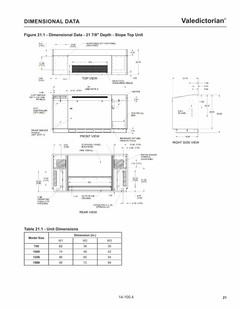
Figure 21.1 - Dimensional Data - 21 7/8" Depth - Slope Top Unit
Model SizeDimension (in.)
W1 W2 W3
750 62 36 30
1000 74 48 42
1250 86 60 54
1500 98 72 66
Table 21.1 - Unit Dimensions
DIMENSIONAL DATA
22 14-100.4
Valedictorian®
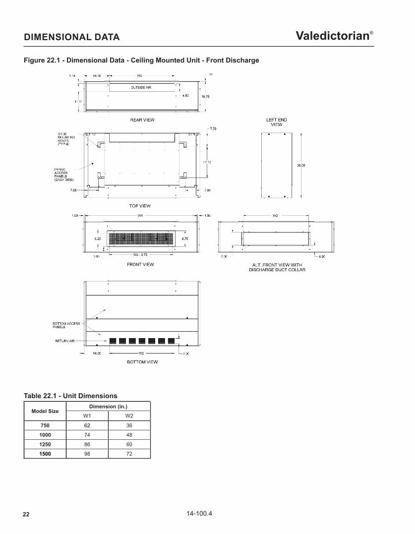
Figure 22.1 - Dimensional Data - Ceiling Mounted Unit - Front Discharge
Model SizeDimension (in.)
W1 W2
750 62 36
1000 74 48
1250 86 60
1500 98 72
Table 22.1 - Unit Dimensions
DIMENSIONAL DATA
2314-100.4
Valedictorian®
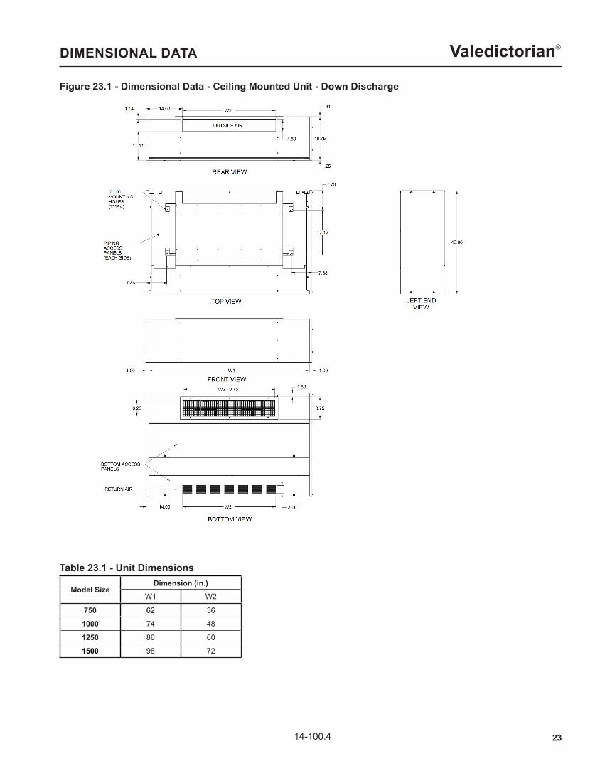
Figure 23.1 - Dimensional Data - Ceiling Mounted Unit - Down Discharge
Model SizeDimension (in.)
W1 W2
750 62 36
1000 74 48
1250 86 60
1500 98 72
Table 23.1 - Unit Dimensions
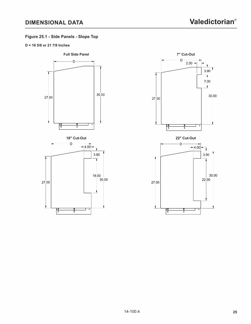
DIMENSIONAL DATA

24 14-100.4
Valedictorian®
Figure 24.1 - Side Panels - Flat Top
DIMENSIONAL DATA
Full Side Panel
D = 16 5/8 or 21 7/8 Inches
7" Cut-Out
18" Cut-Out 22" Cut-Out
2" Step Down (21 7/8" Depth Only)
2514-100.4
Valedictorian®
Figure 25.1 - Side Panels - Slope Top
DIMENSIONAL DATA
Full Side Panel
D = 16 5/8 or 21 7/8 Inches
7" Cut-Out
18" Cut-Out 22" Cut-Out
26 14-100.4
Valedictorian®
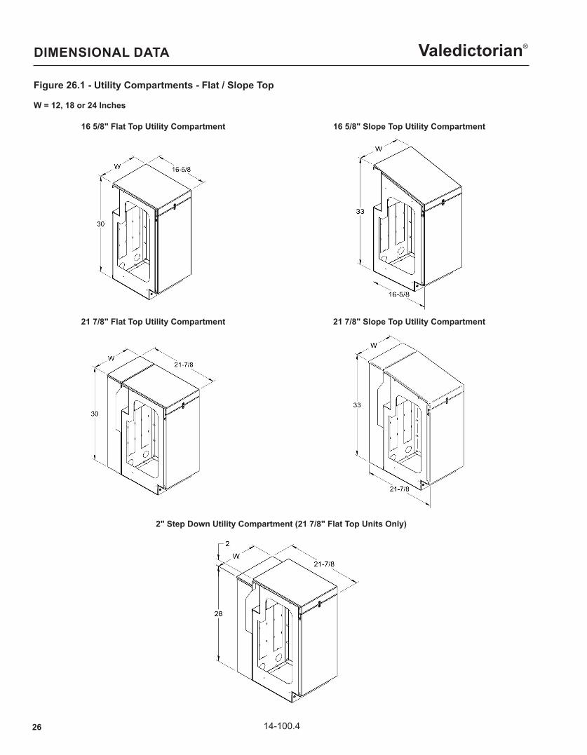
Figure 26.1 - Utility Compartments - Flat / Slope Top
DIMENSIONAL DATA
16 5/8" Flat Top Utility Compartment
W = 12, 18 or 24 Inches
16 5/8" Slope Top Utility Compartment
21 7/8" Flat Top Utility Compartment 21 7/8" Slope Top Utility Compartment
2" Step Down Utility Compartment (21 7/8" Flat Top Units Only)
2714-100.4
Valedictorian®
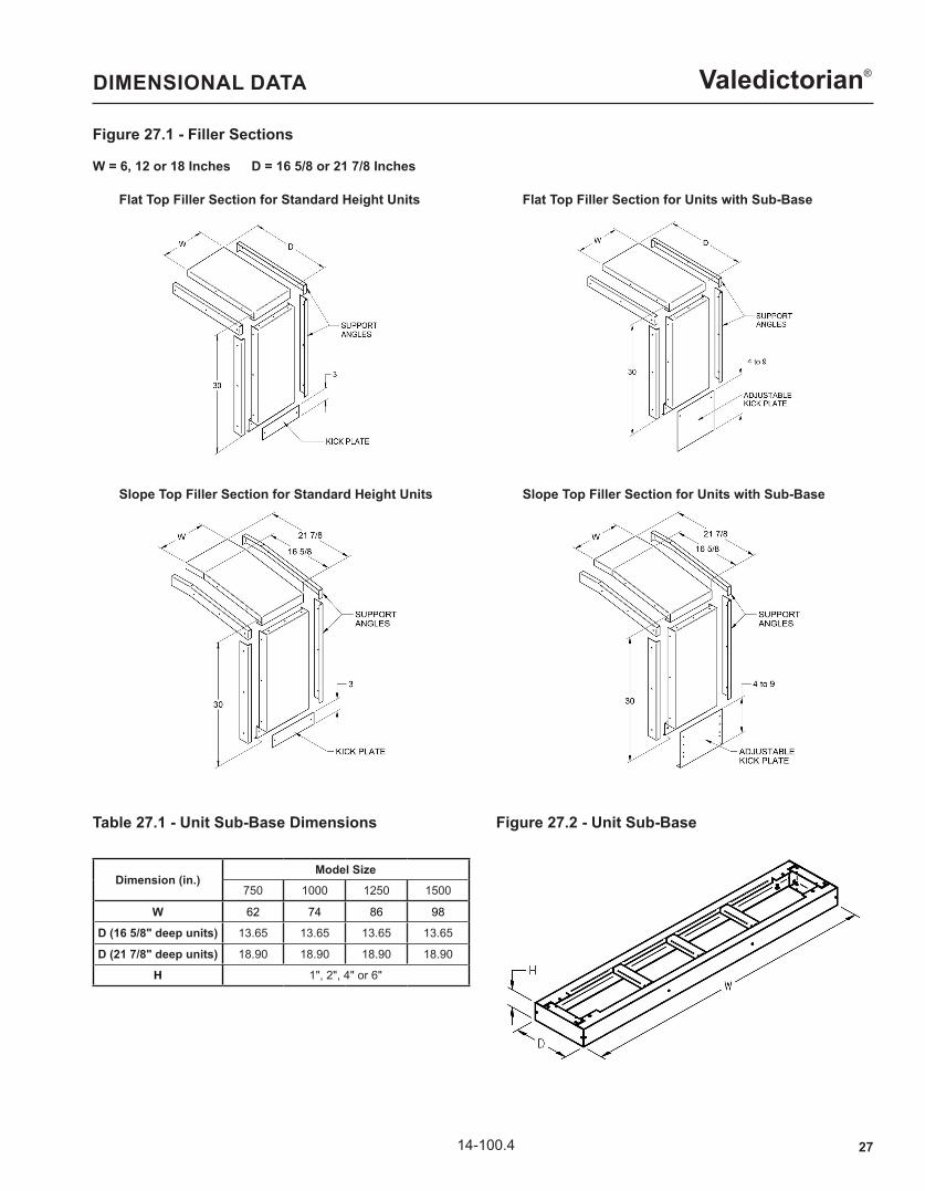
Figure 27.1 - Filler Sections
DIMENSIONAL DATA
Flat Top Filler Section for Standard Height Units
W = 6, 12 or 18 Inches D = 16 5/8 or 21 7/8 Inches
Flat Top Filler Section for Units with Sub-Base
Slope Top Filler Section for Standard Height Units Slope Top Filler Section for Units with Sub-Base
Figure 27.2 - Unit Sub-Base
Dimension (in.)Model Size
750 1000 1250 1500
W 62 74 86 98
D (16 5/8" deep units) 13.65 13.65 13.65 13.65
D (21 7/8" deep units) 18.90 18.90 18.90 18.90
H 1", 2", 4" or 6"
Table 27.1 - Unit Sub-Base Dimensions

28 14-100.4
Valedictorian®
Figure 28.1 - Duct Flange
DIMENSIONAL DATA
Dimension (in.)Model Size
750 1000 1250 1500
A 30.19 42.19 54.19 66.19
Table 28.1 - Duct Flange Dimensions
Figure 28.2 - Wall Sleeve Figure 28.3 - Louver
Dimension (in.)Model Size
750 1000 1250 1500
A 36 48 60 72
B 35.5 47.5 59.5 71.5
Table 28.2 - Wall Sleeve and Louver Dimensions

2914-100.4
Valedictorian®PIPING COMPONENTS
Modine offers the following piping components: Modulating Control Valve, 2-way or 3-way - for Valve Control units (Digit 3 = V) 2-Position Control Valve, 2-way or 3-way - for Face & Bypass units (Digit 3 = F) Balancing Valve Circuit Setter Drain with Hose Bib Shut Off Valves Strainer Piping components can either be shipped loose for field installation or factory assembled and shipped installed to the unit. Shipped loose piping components are available in ½” and ¾” sizes for chilled water units and ½” for hot water units. Piping components shipped installed to the unit are ¾” for chilled water and ½" for hot water.
Figure 29.1 - Typical 2-Way Piping Diagram
Figure 29.2 - Typical 3-Way Piping Diagram
30 14-100.4
Valedictorian®
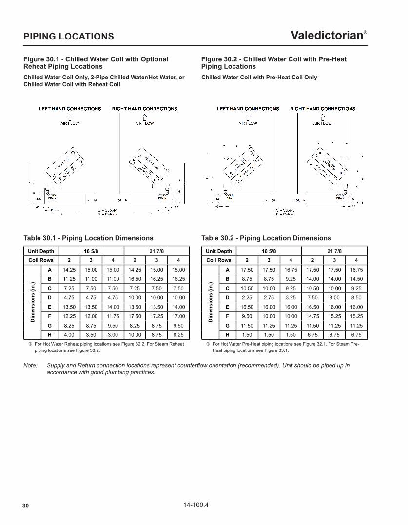
Figure 30.1 - Chilled Water Coil with Optional Reheat Piping Locations
PIPING LOCATIONS
Chilled Water Coil Only, 2-Pipe Chilled Water/Hot Water, or Chilled Water Coil with Reheat Coil
Table 30.1 - Piping Location Dimensions
j For Hot Water Reheat piping locations see Figure 32.2. For Steam Reheat piping locations see Figure 33.2.
Unit Depth 16 5/8 21 7/8Coil Rows 2 3 4 2 3 4
Dim
ensi
ons
(in.)
A 14.25 15.00 15.00 14.25 15.00 15.00
B 11.25 11.00 11.00 16.50 16.25 16.25
C 7.25 7.50 7.50 7.25 7.50 7.50
D 4.75 4.75 4.75 10.00 10.00 10.00
E 13.50 13.50 14.00 13.50 13.50 14.00
F 12.25 12.00 11.75 17.50 17.25 17.00
G 8.25 8.75 9.50 8.25 8.75 9.50
H 4.00 3.50 3.00 10.00 8.75 8.25
Figure 30.2 - Chilled Water Coil with Pre-Heat Piping LocationsChilled Water Coil with Pre-Heat Coil Only
Table 30.2 - Piping Location Dimensions
j For Hot Water Pre-Heat piping locations see Figure 32.1. For Steam Pre- Heat piping locations see Figure 33.1.
Unit Depth 16 5/8 21 7/8Coil Rows 2 3 4 2 3 4
Dim
ensi
ons
(in.)
A 17.50 17.50 16.75 17.50 17.50 16.75
B 8.75 8.75 9.25 14.00 14.00 14.50
C 10.50 10.00 9.25 10.50 10.00 9.25
D 2.25 2.75 3.25 7.50 8.00 8.50
E 16.50 16.00 16.00 16.50 16.00 16.00
F 9.50 10.00 10.00 14.75 15.25 15.25
G 11.50 11.25 11.25 11.50 11.25 11.25
H 1.50 1.50 1.50 6.75 6.75 6.75
Note: SupplyandReturnconnectionlocationsrepresentcounterfloworientation(recommended).Unitshouldbepipedupin accordancewithgoodplumbingpractices.
3114-100.4
Valedictorian®
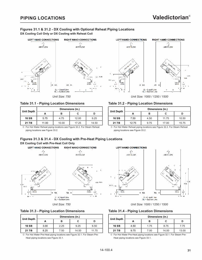
Figures 31.1 & 31.2 - DX Cooling with Optional Reheat Piping Locations
PIPING LOCATIONS
DX Cooling Coil Only or DX Cooling with Reheat Coil
Figures 31.3 & 31.4 - DX Cooling with Pre-Heat Piping LocationsDX Cooling Coil with Pre-Heat Coil Only
Unit DepthDimensions (in.)
A B C D
16 5/8 5.75 4.75 12.00 9.25
21 7/8 11.00 10.00 17.25 14.50
Table 31.1 - Piping Location Dimensions
Table 31.3 - Piping Location Dimensions
j For Hot Water Reheat piping locations see Figure 32.2. For Steam Reheat piping locations see Figure 33.2.
j For Hot Water Pre-Heat piping locations see Figure 32.1. For Steam Pre- Heat piping locations see Figure 33.1.
Unit Size: 750 Unit Size: 1000 / 1250 / 1500
Unit DepthDimensions (in.)
A B C D
16 5/8 7.50 4.50 11.75 10.50
21 7/8 12.75 9.75 17.00 15.75
Table 31.2 - Piping Location Dimensions
j For Hot Water Reheat piping locations see Figure 32.2. For Steam Reheat piping locations see Figure 33.2.
Unit Size: 750 Unit Size: 1000 / 1250 / 1500
Unit DepthDimensions (in.)
A B C D
16 5/8 3.00 2.25 9.25 6.50
21 7/8 8.25 7.50 14.50 11.75
Unit DepthDimensions (in.)
A B C D
16 5/8 4.50 1.75 8.75 7.75
21 7/8 9.75 7.00 14.00 13.00
Table 31.4 - Piping Location Dimensions
j For Hot Water Pre-Heat piping locations see Figure 32.1. For Steam Pre- Heat piping locations see Figure 33.1.

32 14-100.4
Valedictorian®PIPING LOCATIONS
Figure 32.1 - Hot Water Heating Coil PipingLocationsHot Water Heating Coil Only or Chilled Water/DX Cooling Coil with Hot Water Pre-Heat Coil
Table 32.1 - Piping Location Dimensions
j For Chilled Water piping locations see Figure 30.2. For DX Cooling piping locations see Figures 31.3 & 31.4.
Unit Depth 16 5/8 21 7/8Coil Rows 1 2 1 2
Dim
ensi
ons
(in.)
A 14.25 14.25 14.25 14.25
B 11.50 11.25 16.75 16.50
C 7.00 7.25 7.00 7.25
D 5.00 4.75 10.25 10.00
E 13.50 13.50 13.50 13.50
F 12.00 12.25 17.25 17.50
G 8.25 8.25 8.25 8.25
H 4.00 4.00 9.25 9.25
Figure 32.2 - Hot Water Reheat Coil PipingLocationsChilled Water/DX Cooling Coil with Hot Water Reheat Coil
Table 32.2 - Piping Location Dimensions
j For Chilled Water piping locations see Figure 30.1. For DX Cooling piping locations see Figures 31.1 & 31.2.
Unit Depth 16 5/8 21 7/8Coil Rows 1 2 1 2
Dim
ensi
ons
(in.)
A 17.50 17.50 17.50 17.50
B 8.75 8.75 14.00 14.00
C 10.25 10.50 10.25 10.50
D 2.25 2.25 7.50 7.50
E 16.75 16.50 16.75 16.50
F 9.50 9.50 14.75 14.75
G 11.50 11.50 11.50 11.50
H 1.25 1.50 6.50 6.75
Note: SupplyandReturnconnectionlocationsrepresentcounterfloworientation(recommended).Unitshouldbepipedupin accordancewithgoodplumbingpractices.
3314-100.4
Valedictorian®
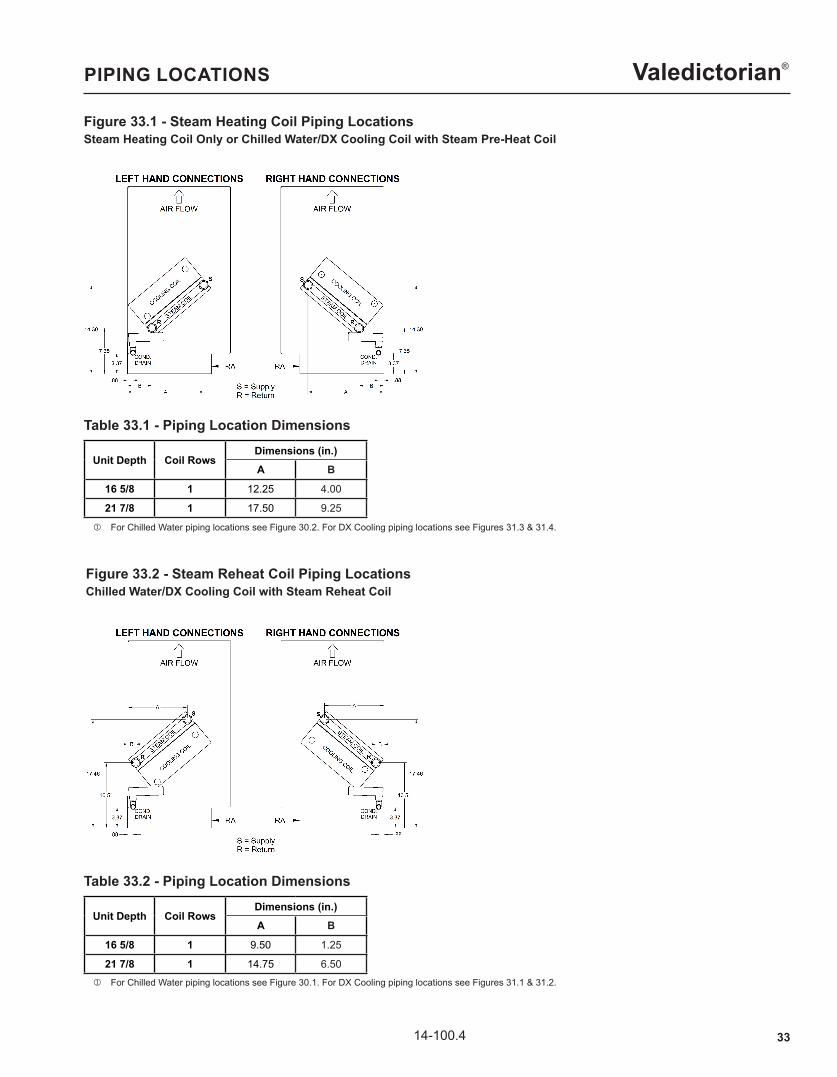
Figure 33.1 - Steam Heating Coil Piping Locations
PIPING LOCATIONS
Steam Heating Coil Only or Chilled Water/DX Cooling Coil with Steam Pre-Heat Coil
Figure 33.2 - Steam Reheat Coil Piping LocationsChilled Water/DX Cooling Coil with Steam Reheat Coil
Unit Depth Coil RowsDimensions (in.)A B
16 5/8 1 12.25 4.00
21 7/8 1 17.50 9.25
Table 33.1 - Piping Location Dimensions
Unit Depth Coil RowsDimensions (in.)A B
16 5/8 1 9.50 1.25
21 7/8 1 14.75 6.50
Table 33.2 - Piping Location Dimensions
j For Chilled Water piping locations see Figure 30.2. For DX Cooling piping locations see Figures 31.3 & 31.4.
j For Chilled Water piping locations see Figure 30.1. For DX Cooling piping locations see Figures 31.1 & 31.2.
34 14-100.4
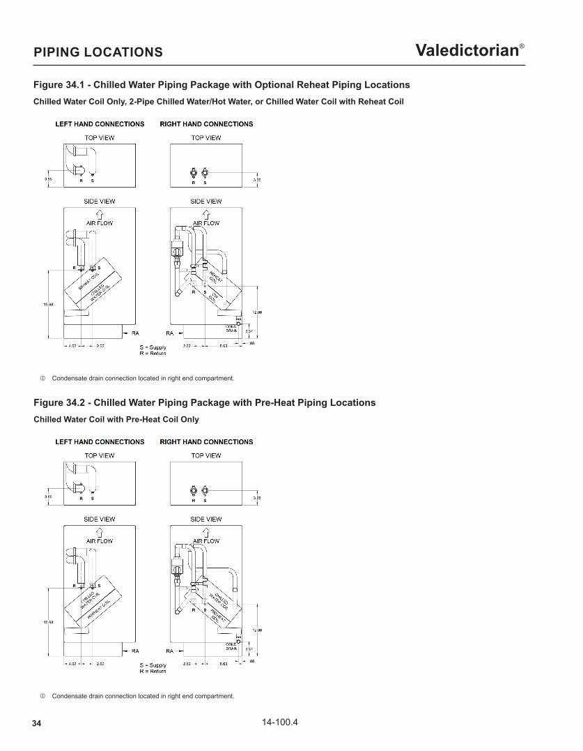
Valedictorian®PIPING LOCATIONS
Figure 34.1 - Chilled Water Piping Package with Optional Reheat Piping LocationsChilled Water Coil Only, 2-Pipe Chilled Water/Hot Water, or Chilled Water Coil with Reheat Coil
Figure 34.2 - Chilled Water Piping Package with Pre-Heat Piping LocationsChilled Water Coil with Pre-Heat Coil Only
j Condensate drain connection located in right end compartment.
j Condensate drain connection located in right end compartment.
3514-100.4
Valedictorian®PIPING LOCATIONS
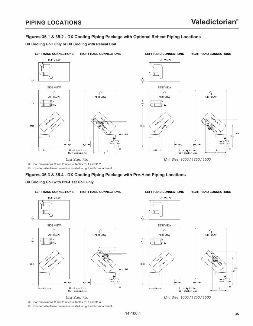
Figures 35.1 & 35.2 - DX Cooling Piping Package with Optional Reheat Piping LocationsDX Cooling Coil Only or DX Cooling with Reheat Coil
Figures 35.3 & 35.4 - DX Cooling Piping Package with Pre-Heat Piping LocationsDX Cooling Coil with Pre-Heat Coil Only
Unit Size: 750 Unit Size: 1000 / 1250 / 1500
Unit Size: 750 Unit Size: 1000 / 1250 / 1500
j For Dimensions C and D refer to Tables 31.1 and 31.2. k Condensate drain connection located in right end compartment.
j For Dimensions C and D refer to Tables 31.3 and 31.4. k Condensate drain connection located in right end compartment.
36 14-100.4
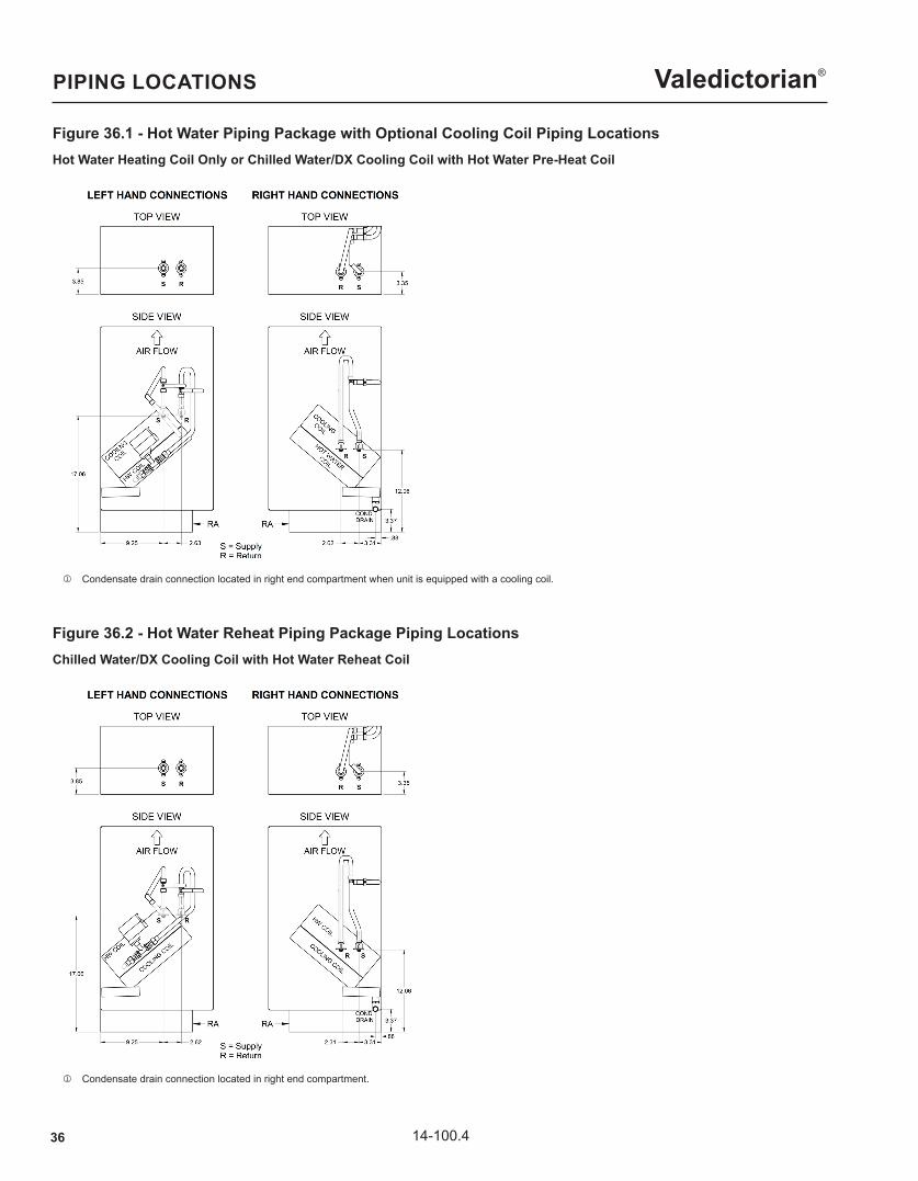
Valedictorian®PIPING LOCATIONS
Figure 36.1 - Hot Water Piping Package with Optional Cooling Coil Piping LocationsHot Water Heating Coil Only or Chilled Water/DX Cooling Coil with Hot Water Pre-Heat Coil
Figure 36.2 - Hot Water Reheat Piping Package Piping LocationsChilled Water/DX Cooling Coil with Hot Water Reheat Coil
j Condensate drain connection located in right end compartment when unit is equipped with a cooling coil.
j Condensate drain connection located in right end compartment.
3714-100.4
Valedictorian®PIPING LOCATIONS
Figure 37.1 - Steam Heating Piping Package with Optional Cooling Coil Piping LocationsSteam Heating Coil Only or Chilled Water/DX Cooling Coil with Steam Pre-Heat Coil
Figure 37.2 - Steam Reheat Piping Package Piping LocationsChilled Water/DX Cooling Coil with Steam Reheat Coil
j For Dimensions A and B refer to Table 33.1. k Condensate drain connection located in right end compartment when unit is equipped with a cooling coil.
j For Dimensions A and B refer to Tabe 33.2. k Condensate drain connection located in right end compartment.
38 14-100.4
Valedictorian®
Up Flow Condenser, Model: YCE18 through YCE36Standard Features
• Quality Condenser Coils - The coil is constructed of aluminum microchannel tubing and enhanced aluminum fins for increased efficiency and corrosion protection
• Protected Compressor - The compressor is internally protected against high pressure, temperature, and externally by a factory installed high pressure switch. This is accomplished by simultaneous operation of high pressure relief valve and a temperature sensor which protects the compressor if undesirable operating conditions occur. A liquid line filter-drier further protects the compressor.
• Hard Start Kit - Provides increased starting torque for areas with low voltage.
• Durable Finish - The cabinet is made of pre-painted steel. The pre-treated galvanized steel provides a better paint to steel bond, which resists corrosion and rust creep. Special primer formulas and matted-textured finish ensure less fading when exposed to sunlight.
• Lower Installed Cost - Installation time and costs are reduced by easy power and control wiring connections. Available in sweat connect models only. The unit contains enough refrigerant for matching indoor coils and 15 feet of interconnecting piping. The small base dimension means less space is required on the ground or roof
• Top Dicharge - The warm air from the top mounted fan is blown up and away from the structure and any landscaping. This allows compact location on multi-unit applications.
• Low Operating Sound Level – The upward air flow carries the normal operating noise away from the living area. The rigid top panel effectively isolates any motor sound. Isolator mounted compressor and rippled fins of the condenser coil muffle the normal fan motor and compressor operating sounds.
• Low Maintenance – Long life permanently lubricated motor-bearings need no annual servicing.
• Easy Service Access – Fully exposed refrigerant connections and a single panel covering the electrical controls makes for easy servicing of the unit.
• Secured Service Valves – Secured re-usable service valves are provided on both the liquid and vapor sweat connections for ease of evacuating and charging.
• U.L. and C.U.L. Listed – Approved for outdoor application.
Field Installed Accessories
• Low Ambient Kit – Fan Cycle Kit for operation down to 0°F outside temperature.
OUTDOOR CONDENSING UNIT
Dimension (in.)Condensing Unit Model
YCE18 YCE24 YCE30 YCE36
A = Height 30 26-3/4 26-3/4 30
B = Depth 24 29-1/4 29-1/4 29-1/4
C = Width 24 29-1/4 29-1/4 29-1/4
Table 38.1 - Outdoor Condensing Unit Dimensions Figure 38.1 - Outdoor Condensing Unit

3914-100.4
Valedictorian®
UnitsCondenser Model
YCE18 YCE24 YCE30 YCE36
PerformanceNominal System Cooling Capacity BTU/h 18,000 24,000 30,000 36,000
Nominal System SEER 14 14 14 14
ConstructionMaterial: Chassis Pre-Treated Galvanized Painted Steel
Color Champagne
Dimensions/WeightsHeight (includes Fan Guard) in 30 26-3/4 26-3/4 30
Width in 24 29-1/4 29-1/4 29-1/4
Depth in 24 29-1/4 29-1/4 29-1/4
Weight lb 125 135 140 145
CompressorType Recip Recip Recip Recip
Crankcase Heater Fitted No No No No
Condenser
Coil Construction Plate Fin Microchannel
Plate Fin Microchannel
Plate Fin Microchannel
Plate Fin Microchannel
Connections jSuction in 3/4 3/4 3/4 3/4Liquid in 3/8 3/8 3/8 3/8
Refrigerant ChargeCondenser-factory charge lbs-oz 3 - 8 3 - 12 3 - 14 4 - 1
Charge Required-Per Foot of Pipework oz 0.62 0.62 0.62 0.62
Electrical DataPower Supply 208-230V/1Ph/60Hz
MCA A 12.7 14.8 18.4 19.6
Maximum Overcurrent Device Amps k A 20 25 30 30
Minimum Overcurrent Device Amps l A 15 15 20 20
CompressorRated Load Amps (RLA) A 9.7 11.2 14.1 14.7
Locked Rotor Amps (LRA) A 46.0 60.8 73.0 75.0
Condenser FanRated Load Amps (RLA) A 0.64 0.80 0.80 1.30
Rated Horsepower HP 1/12 1/8 1/8 1/4
Sound Data
Sound Power Rating m dBA 73.0 74.0 74.0 74.0
Table 39.1 - Technical, Electrical & Sound Data - Outdoor Condensing Unit
j Refrigerant line sizes should always match condensing unit connection sizes. k Dual element fuses or HACR circuit breakers. Maximum allowable overcurrent protection. l Dual element fuses or HACR circuit breakers. Minimum recommended overcurrent protection. m Rated in accordance with AHRI Standard 270.
OUTDOOR CONDENSING UNIT

Products from Modine are designed to provide indoor air-comfort and ventilation solutions for residential, commercial, institutional and industrial applications. Whatever your heating, ventilating and air conditioning requirements, Modine has the product to satisfy your needs, including:
HVAC• Unit Heaters: – Gas – Hydronic – Electric – Oil• Ceiling Cassettes• Duct Furnaces• Hydronic Cabinet Unit Heaters, Fin Tube, Convectors• Infrared Heaters• Make-up Air Systems• Unit Ventilators
Ventilation• Packaged Rooftop Ventilation
School Products• Vertical Packaged Classroom HVAC: – DX Cooling/Heat Pump – Water/Ground Source Heat Pump – Horizontal/Vertical Unit Ventilators
Specific catalogs are available for each product. Catalogs 75-136 and 75-137 provide details on all Modine HVAC equipment.
Modine Manufacturing Company1500 DeKoven AvenueRacine, Wisconsin 53403-2552Phone: 1.800.828.4328 (HEAT)www.modinehvac.com© Modine Manufacturing Company 2020
The Modine brand has been the
industry standard since Arthur B.
Modine invented and patented
the first lightweight, suspended
hydronic unit heater in 1923.
No other manufacturer can
provide the combined application
flexibility, technical expertise and
fast delivery found at Modine.
Consult your local Modine
distributor for help in solving your
indoor air problems.