vertical unit ventilator - rsi comp · page 8 nesbitt vertical unit ventilator (vuv) 1.0 general...
TRANSCRIPT

VERTICAL UNIT VENTILATOR
Comfort ~ Energy Efficiency ~ Indoor Air Quality Low Installed Cost ~ Ease of Service & Maintenance
Replacement for existing EDPAC SE Units
COPYRIGHT 2002 RSI COMPANY

Page 2
Table of Contents
OUTER CABINET DIMENSIONS Page 3
UNIT CHASSIS DIMENSIONS Page 4
OUTDOOR WALL LOUVER DETAILS Page 5
PERFORMANCE DATA / UNIT WEIGHTS Page 6
ELECTRICAL DATA Page 7
SPECIFICATIONS Page 8
SPECIFICATIONS Page 9
START-UP PROCEDURES / MAINTENANCE Page 10
WARRANTY Page 11
COPYRIGHT 2002 RSI COMPANY

RSI NESBITT Page 3
8478 [2156]
3214 [819]
578 [149]
1 [25]
112 [38]
8 [203]
118 [28]
4212 [1080]
3734 [959]
2738 [695]
1358 [346]
3514 [895]
114 [32]
1318 [333]
1614 [413]
1318 [333]
1614 [413]
114 [32]
REMOTE CONTROL ANDDRY COOLER CONTROL
WIRING
ELECTRIC SERCICEENTRANCE
XC/XWPIPING
378 [98] 37
8 [98]1 18 " SWEATCONDENSATE DRAIN
SIDE FRONT BACK
TOP
COPYRIGHT 2002 RSI COMPANY
OUTER CABINET DIMENSIONS MODEL “VUV” (SEHA)
APPROXIMATE SHIPPING WEIGHT
VUV (SEHA) LBS
CABINET CHASSIS
400 850
Page 4
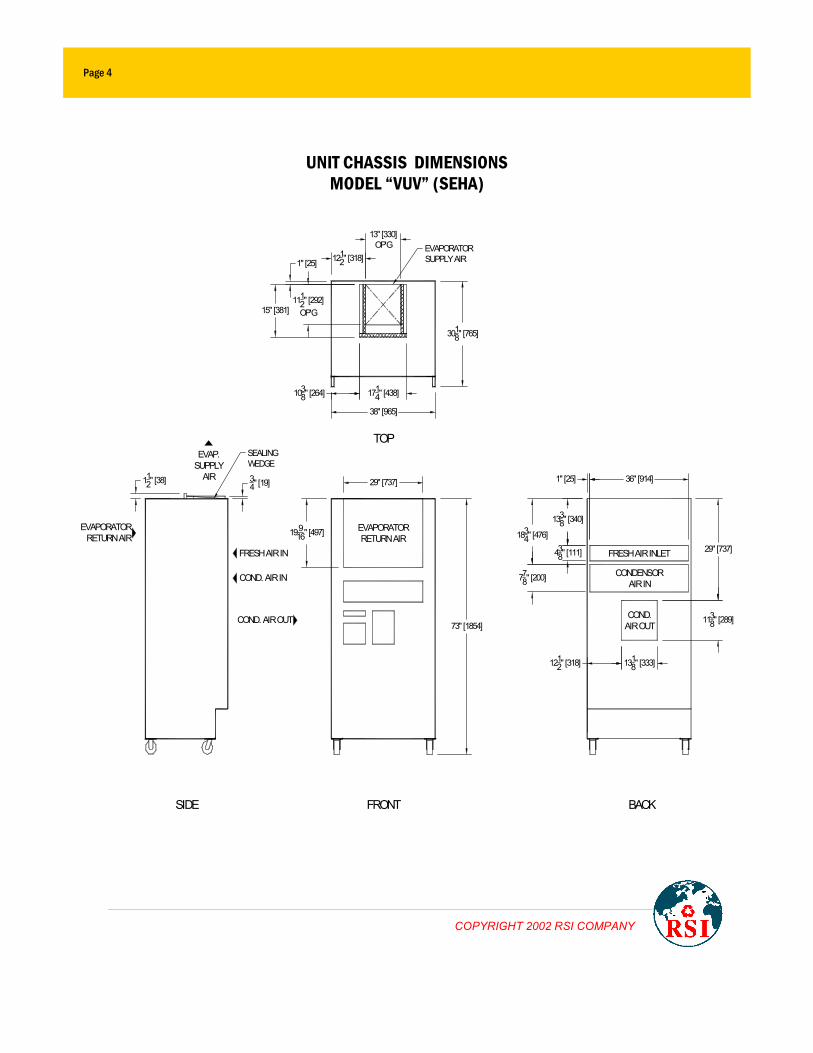
UNIT CHASSIS DIMENSIONS MODEL “VUV” (SEHA)
3018" [765]
38" [965]
1212" [318]
13" [330]OP'G
73" [1854]
1338" [340]
1834" [476]
1" [25] 36" [914]
438" [111]
778" [200]
1212" [318] 131
8" [333]
29" [737]
1138" [289]
SIDE FRONT BACK
TOP
19916" [497]
29" [737]
1" [25]
1112" [292]OP'G15" [381]
1038" [264] 1714" [438]
34" [19]11
2" [38]
EVAPORATORRETURN AIR
FRESH AIR INLET
CONDENSORAIR IN
COND.AIR OUT
FRESH AIR IN
COND. AIR IN
COND. AIR OUT
EVAPORATORSUPPLY AIR
EVAPORATORRETURN AIR
EVAP.SUPPLY
AIR
SEALINGWEDGE
COPYRIGHT 2002 RSI COMPANY

RSI NESBITT Page 5
VUV (SEHA) TYPICAL INSTALLATION DIMENSIONS
FOR OUTDOOR WALL LOUVER (Requires 700 Sq. In. [ 1778 Sq. Cm. ] Free Area)
3714 [945]
3558 [905]
281316 [731]
2718 [689]
3734 [958]
12 [305]
2738 [695]
1334 [349]
1 [25]
SEPERATORBAFFLE ON
OUTERCABINET
FLA
NG
E O
N B
AC
K O
FN
ES
BIT
T C
AB
INE
T
INSULATION
ONE (1) LB/CU. FT.(16 KG/CU.M.)DENSITY FIBERGLASS INSULATION
FOIL BACKING (FACES AIR STREAM)
WATERPROOFADHESIVE
INSULATION
REQUIRED INSULATION CROSS SECTION
FRESHAIR
DISCHARGEAIR
BAFFLE MUST MEET END OF LOUVER
MINIMUM WALL OPENING SIZE
(2712" H X 36" W)(699 X 914)
WARNING:ALL INTERIOR SURFACES OF FIELD FABRICATED TRANSITION SLEEVE MUST BE INSULATED WITH ONE POUND DENSITY, FOIL BACKED FIBERGLASS INSULATION APPLY LAMINATING TYPE WATERPROOF ADHESIVE TO INTERIOR SURFACES AND INSTALL INSULATION WITH FIBERGLASS SIDE DOWN TO INSURE THAT FOIL SIDE FACES THE AIR STREAM. SEAL ALL JOINTS AND ABUTMENTS WITH RTV SEALANT.
TWO (2) VERTICAL SUPPORTS
COPYRIGHT 2002 RSI COMPANY
DIMENSIONS IN BRACKETS ( ) ARE IN MM WEIGHT = 20 LBS. ( 9 KG. )

Page 6
RSI Nesbitt Vertical Unit Ventilator (VUV)
(SEHA) PERFORMANCE DATA – 60Hz
ITEM SIZE 3 4 5 6 Cooling Capacity Mbh (1) 44.8 53.2 58.8 66.7 Heat Pump Capacity Mbh (2) 43.9 49.7 55.9 61.9 SUPPLY FAN Direct Derive Centrifugal Airflow 1400 1400 1600 1800 Max External Static Pressure inWg 0.38” 0.38” 0.38” 0.38”
EXHAUST FAN
Direct Derive Centrifugal Airflow cfm 100% Modulating 1400 1400 1600 1800 Max External Static Pressure inWg 0.5” 0.5” 0.5” 0.5”
FILTER Type 1” Pleated 80% Arrestance
UNIT WEIGHT Cabinet Lbs. 400 400 400 400 Chassis Lbs. 850 870 885 905 OPTIONS Electric Heat Heating Capacity kW / Mbh 12 / 41 12 / 41 12 / 41 12 / 41 Stages 2 2 2 2 NOTES
(1) Cooling capacity based on Air On 80/67°F Dry/ Wet Bulb and 95°F Ambient (2) Heat Pump capacity based on Air On 70/58.5°F Dry/ Wet Bulb and 47°F Ambient
COPYRIGHT 2002 RSI COMPANY
RSI NESBITT Page 7
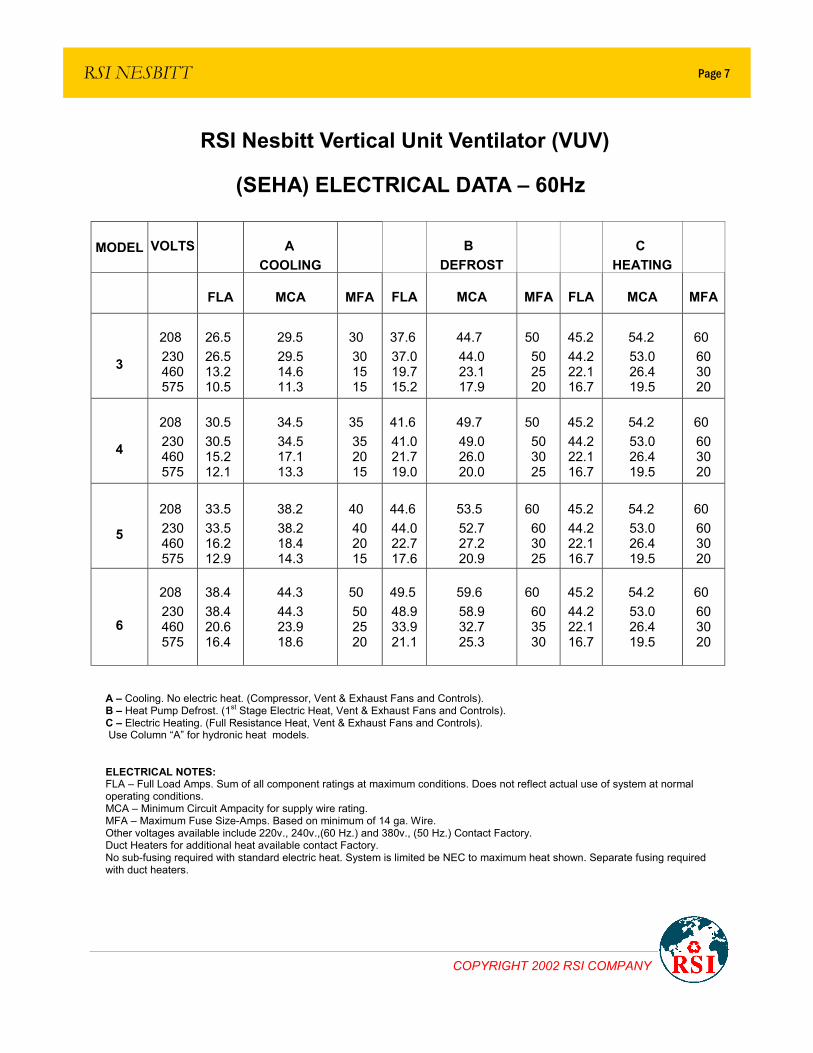
RSI Nesbitt Vertical Unit Ventilator (VUV)
(SEHA) ELECTRICAL DATA – 60Hz
A – Cooling. No electric heat. (Compressor, Vent & Exhaust Fans and Controls). B – Heat Pump Defrost. (1st Stage Electric Heat, Vent & Exhaust Fans and Controls). C – Electric Heating. (Full Resistance Heat, Vent & Exhaust Fans and Controls). Use Column “A” for hydronic heat models. ELECTRICAL NOTES: FLA – Full Load Amps. Sum of all component ratings at maximum conditions. Does not reflect actual use of system at normal operating conditions. MCA – Minimum Circuit Ampacity for supply wire rating. MFA – Maximum Fuse Size-Amps. Based on minimum of 14 ga. Wire. Other voltages available include 220v., 240v.,(60 Hz.) and 380v., (50 Hz.) Contact Factory. Duct Heaters for additional heat available contact Factory. No sub-fusing required with standard electric heat. System is limited be NEC to maximum heat shown. Separate fusing required with duct heaters.
MODEL VOLTS A COOLING
B DEFROST
C HEATING
FLA MCA MFA FLA MCA MFA FLA MCA MFA
3
208 230 460 575
26.5 26.5 13.2 10.5
29.5 29.5 14.6 11.3
30 30 15 15
37.6 37.0 19.7 15.2
44.7 44.0 23.1 17.9
50 50 25 20
45.2 44.2 22.1 16.7
54.2 53.0 26.4 19.5
60 60 30 20
4
208 230 460 575
30.5 30.5 15.2 12.1
34.5 34.5 17.1 13.3
35 35 20 15
41.6 41.0 21.7 19.0
49.7 49.0 26.0 20.0
50 50 30 25
45.2 44.2 22.1 16.7
54.2 53.0 26.4 19.5
60 60 30 20
5
208 230 460 575
33.5 33.5 16.2 12.9
38.2 38.2 18.4 14.3
40 40 20 15
44.6 44.0 22.7 17.6
53.5 52.7 27.2 20.9
60 60 30 25
45.2 44.2 22.1 16.7
54.2 53.0 26.4 19.5
60 60 30 20
6
208 230 460 575
38.4 38.4 20.6 16.4
44.3 44.3 23.9 18.6
50 50 25 20
49.5 48.9 33.9 21.1
59.6 58.9 32.7 25.3
60 60 35 30
45.2 44.2 22.1 16.7
54.2 53.0 26.4 19.5
60 60 30 20
COPYRIGHT 2002 RSI COMPANY
Page 8
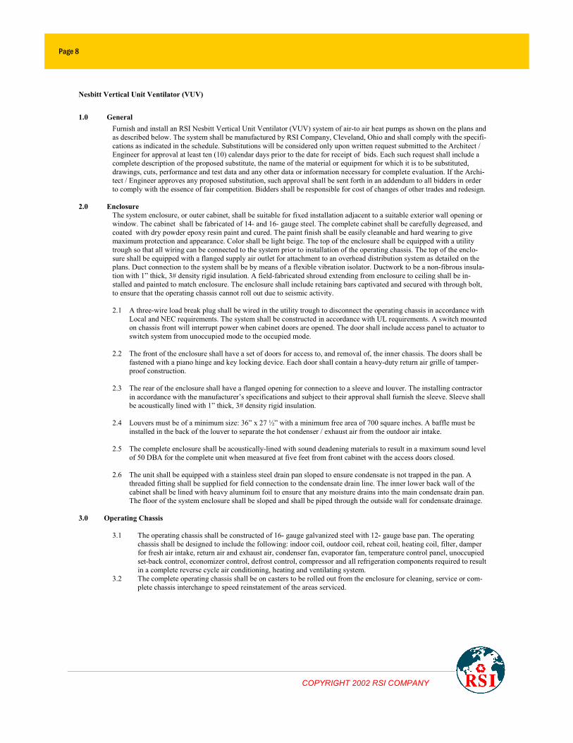
Nesbitt Vertical Unit Ventilator (VUV)
1.0 General Furnish and install an RSI Nesbitt Vertical Unit Ventilator (VUV) system of air-to air heat pumps as shown on the plans and as described below. The system shall be manufactured by RSI Company, Cleveland, Ohio and shall comply with the specifi-cations as indicated in the schedule. Substitutions will be considered only upon written request submitted to the Architect / Engineer for approval at least ten (10) calendar days prior to the date for receipt of bids. Each such request shall include a complete description of the proposed substitute, the name of the material or equipment for which it is to be substituted, drawings, cuts, performance and test data and any other data or information necessary for complete evaluation. If the Archi-tect / Engineer approves any proposed substitution, such approval shall be sent forth in an addendum to all bidders in order to comply with the essence of fair competition. Bidders shall be responsible for cost of changes of other trades and redesign.
2.0 Enclosure
The system enclosure, or outer cabinet, shall be suitable for fixed installation adjacent to a suitable exterior wall opening or window. The cabinet shall be fabricated of 14- and 16- gauge steel. The complete cabinet shall be carefully degreased, and coated with dry powder epoxy resin paint and cured. The paint finish shall be easily cleanable and hard wearing to give maximum protection and appearance. Color shall be light beige. The top of the enclosure shall be equipped with a utility trough so that all wiring can be connected to the system prior to installation of the operating chassis. The top of the enclo-sure shall be equipped with a flanged supply air outlet for attachment to an overhead distribution system as detailed on the plans. Duct connection to the system shall be by means of a flexible vibration isolator. Ductwork to be a non-fibrous insula-tion with 1” thick, 3# density rigid insulation. A field-fabricated shroud extending from enclosure to ceiling shall be in-stalled and painted to match enclosure. The enclosure shall include retaining bars captivated and secured with through bolt, to ensure that the operating chassis cannot roll out due to seismic activity.
2.1 A three-wire load break plug shall be wired in the utility trough to disconnect the operating chassis in accordance with
Local and NEC requirements. The system shall be constructed in accordance with UL requirements. A switch mounted on chassis front will interrupt power when cabinet doors are opened. The door shall include access panel to actuator to switch system from unoccupied mode to the occupied mode.
2.2 The front of the enclosure shall have a set of doors for access to, and removal of, the inner chassis. The doors shall be
fastened with a piano hinge and key locking device. Each door shall contain a heavy-duty return air grille of tamper-proof construction.
2.3 The rear of the enclosure shall have a flanged opening for connection to a sleeve and louver. The installing contractor
in accordance with the manufacturer’s specifications and subject to their approval shall furnish the sleeve. Sleeve shall be acoustically lined with 1” thick, 3# density rigid insulation.
2.4 Louvers must be of a minimum size: 36” x 27 ½” with a minimum free area of 700 square inches. A baffle must be
installed in the back of the louver to separate the hot condenser / exhaust air from the outdoor air intake.
2.5 The complete enclosure shall be acoustically-lined with sound deadening materials to result in a maximum sound level of 50 DBA for the complete unit when measured at five feet from front cabinet with the access doors closed.
2.6 The unit shall be equipped with a stainless steel drain pan sloped to ensure condensate is not trapped in the pan. A
threaded fitting shall be supplied for field connection to the condensate drain line. The inner lower back wall of the cabinet shall be lined with heavy aluminum foil to ensure that any moisture drains into the main condensate drain pan. The floor of the system enclosure shall be sloped and shall be piped through the outside wall for condensate drainage.
3.0 Operating Chassis
3.1 The operating chassis shall be constructed of 16- gauge galvanized steel with 12- gauge base pan. The operating chassis shall be designed to include the following: indoor coil, outdoor coil, reheat coil, heating coil, filter, damper for fresh air intake, return air and exhaust air, condenser fan, evaporator fan, temperature control panel, unoccupied set-back control, economizer control, defrost control, compressor and all refrigeration components required to result in a complete reverse cycle air conditioning, heating and ventilating system.
3.2 The complete operating chassis shall be on casters to be rolled out from the enclosure for cleaning, service or com-plete chassis interchange to speed reinstatement of the areas serviced.
COPYRIGHT 2002 RSI COMPANY
RSI NESBITT Page 9
4.0 Refrigeration System
4.1 The refrigeration system shall consist of a hermetic scroll heat pump grade compressor equipped with a crankcase heater to guard against liquid flood-back conditions and elimination of oil foaming on start-up. The compressor shall be mounted on vibration absorbers to ensure quiet operation and fitted with a sound dampening jacket. The compres-sor shall be protected against excessive motor temperatures and current by means of an internal overload protector. A suction-throttling valve shall be incorporated to prevent frosting of the evaporator coil.
4.2 The refrigeration system shall contain an externally equalized expansion valve, sight glass, and a filter drier. The evaporator and condenser coil shall be constructed of aluminum fins mechanically bonded to copper tubes. High and low refrigerant pressure switches shall be installed. These switches shall be adjustable, contain manual resets and be accessible from the front electrical panel. Service valves for checking operating pressures and reclaiming refrigerant shall be accessible from the front of the unit.
5.0 Fans and Fan Motors
5.1 The forward curved blower wheels shall be constructed from galvanized sheet steel and fitted in a die cast aluminum scroll to ensure long life expectancy. Each motor shall contain internal thermal overload contacts. The supply and exhaust fans shall be statically and dynamically balanced for quiet operation. They shall be of the direct drive design suitable for use with a dual input electronic speed controller. One speed controller shall be fitted for each fan motor.
5.2 The controller shall control the fan at two speeds that are infinitely adjustable by the user. The controller may operate the fans at a minimum speed when the unit is operating in the economy cycle or when the return air temperature is such that neither heating nor cooling is required. During the heating or cooling mode the supply fans) shall run at stan-dard speed. The exhaust fans) shall run at standard speed and operate while the compressor is operating, or while in the purge mode. The speed controller shall be mounted in the control panel outside the air stream and consist of a solid state thyristor that modifies the voltage input to each fan motor(s).
6.0 Filters
Each unit shall be fitted with 1” inch thick disposable pleated filter designed to meet ASHRAE Standard 52-76. The filter shall be treated with a durable, low toxicity, anti-microbial that inhibits the growth of bacteria and fungi on the filter surface.
7.0 Control Damper
A damper system shall control outside air, return air and exhaust air within the unit with outdoor air and room air damper blades suspended on bronze bearings. System shall mix outdoor air, as called for by the automatic control, with return air prior to passing through the coils and air distributing fan. The system shall be capable of exhausting 100% return air from the space. Unit shall be capable of modulating from 0 to 100% outside air.
8.0 Heating Coil An electric heating coil of the capacity as shown on the plans shall be installed down-stream of the cooling coil and the filters.
9.0 Operation Microprocessor Controls – Standard The unit shall be fitted with a programmable microprocessor controller mounted outside of the air stream and specifically de-signed to operate the unit in an energy efficient manner using pre-engineered control strategies. The microprocessor shall deter-mine the mode of operation based on the return air, supply air, and ambient temperatures.
9.1 Unoccupied Operation The cooling and ventilating shall be turned off and the heating coil shall be under control of the “night set-back mode”. The outdoor air damper shall close and the room fan shall operate only after the controller receives a call for heating.
9.2 Occupied Operation The fresh air damper shall automatically move to minimum outdoor air position and the air sup-ply fan operates. Upon a drop in room temperature below the set point of the controller, the compressor discharge gas shall be directed to the indoor coil to provide heated supply air. Upon an increase in the return air temperature above the controller set point, the system shall cool. The outside air changeover sensor shall function, depending on the out-side temperature to further open the outside damper or cause the compressor to operate.
9.3 Economizer Operation When the changeover sensor prevents the compressor operation at low outside ambient, the mixed air temperature controller operates the outside air damper to blend return air and outside air to the adjustable temperature set point. The system shall deliver up to 100% outdoor air if required.
9.4 Auxiliary Electric Heat Option When the outside air temperature is too low for the refrigerant system to provide re-verse cycle heating, the compressor operation shall be locked-out. When this occurs, cycling the electric heating coil as required maintaining the room temperature shall provide heating.
10.0 Start-up and Service
The manufacturer, or shall include first year start-up and service and assign a competent refrigeration service group to completely check each system for refrigerant leaks or other mechanical or electrical failures. After the system is in operation, a qualified refrigeration service contractor shall be responsible for replacement or repair of any faulty equipment for a period of one year after its acceptance by the Architect / Engineer or after the system has been put in op-eration, whichever occurs first.
11.0 Maintenance RSI Company or “authorized trained factory representative” shall instruct the personnel assigned by the “owner” in the proper maintenance of the equipment. The normal maintenance functions, such as changing filters, cleaning drains, inspection of the condenser and evaporator coil, etc., shall be the responsibility of the owner.
COPYRIGHT 2002 RSI COMPANY

RSI Nesbitt Vertical Unit Ventilator (VUV)
START-UP PROCEDURE 1) Before turning on power. Remove front covers from the electrical panel. 2) Check all power wiring and electrical panels for loose connections. 3) Check drains and cabinet for leaks by removing filter and pouring water into condensate pan until it runs out
of cabinet drain system (not on flooring). Reinstall filter. 4) Check damper linkage for proper tightness and operation. 5) Turn on power and check voltage at contactors. See that voltage is within tolerance (plus or minus 10% of
nameplate ratings). 6) Set outside air changeover stat and mixed air stat to 60°F, and damper knob to close. 7) Press occupied switch to start unit. 8) Set minimum position knob so that damper opens about ½” at tip. 9) Check operation of thermostat and economy controls. See operating chart and control wiring (on front of
chassis) for guide to proper sequence. 10) Check operating amperages of fan motors and compressor (on front of chassis). 11) Install electrical panel cover and set control to desired temperature.
MAINTENANCE INSTRUCTIONS
Daily: Shut off blower before sweeping floor to prevent dust from being sucked into machine. Monthly: Inspect filters for excessive dust or dirt – replace if necessary. Clean cabinet exterior with mild soap and water. Vacuum dust from under chassis. Quarterly: Change filters. Annually: Remove chassis for cleaning and inspection.
1) Turn off power to chassis. 2) Disconnect wiring to chassis. 3) Remove cabinet chassis retaining bars. 4) Roll chassis out of cabinet. 5) Clean interior of cabinet. 6) Check drains for free flow. 7) Clean chassis. 8) Remove condenser coil inspection plates from lower sides of chassis.
Check for dust or dirt and clean as necessary. 9) Replace in reverse order of removal.
RSI NESBITT
COPYRIGHT 2002 RSI COMPANY
Page 10
RSI NESBITT
COPYRIGHT 2002 RSI COMPANY
nesbitt Vertical Unit Ventilator
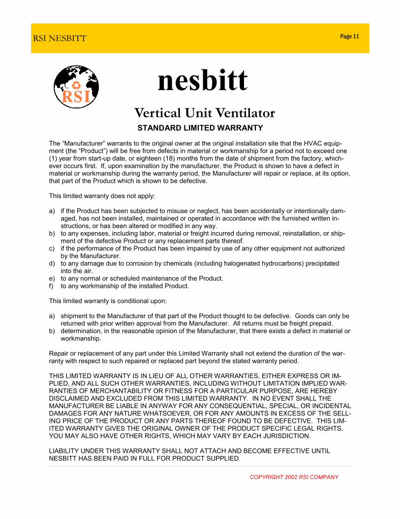
STANDARD LIMITED WARRANTY The “Manufacturer” warrants to the original owner at the original installation site that the HVAC equip-ment (the “Product”) will be free from defects in material or workmanship for a period not to exceed one (1) year from start-up date, or eighteen (18) months from the date of shipment from the factory, which-ever occurs first. If, upon examination by the manufacturer, the Product is shown to have a defect in material or workmanship during the warranty period, the Manufacturer will repair or replace, at its option, that part of the Product which is shown to be defective. This limited warranty does not apply: a) if the Product has been subjected to misuse or neglect, has been accidentally or intentionally dam-
aged, has not been installed, maintained or operated in accordance with the furnished written in-structions, or has been altered or modified in any way.
b) to any expenses, including labor, material or freight incurred during removal, reinstallation, or ship-ment of the defective Product or any replacement parts thereof.
c) if the performance of the Product has been impaired by use of any other equipment not authorized by the Manufacturer.
d) to any damage due to corrosion by chemicals (including halogenated hydrocarbons) precipitated into the air.
e) to any normal or scheduled maintenance of the Product. f) to any workmanship of the installed Product. This limited warranty is conditional upon: a) shipment to the Manufacturer of that part of the Product thought to be defective. Goods can only be
returned with prior written approval from the Manufacturer. All returns must be freight prepaid. b) determination, in the reasonable opinion of the Manufacturer, that there exists a defect in material or
workmanship. Repair or replacement of any part under this Limited Warranty shall not extend the duration of the war-ranty with respect to such repaired or replaced part beyond the stated warranty period. THIS LIMITED WARRANTY IS IN LIEU OF ALL OTHER WARRANTIES, EITHER EXPRESS OR IM-PLIED, AND ALL SUCH OTHER WARRANTIES, INCLUDING WITHOUT LIMITATION IMPLIED WAR-RANTIES OF MERCHANTABILITY OR FITNESS FOR A PARTICULAR PURPOSE, ARE HEREBY DISCLAIMED AND EXCLUDED FROM THIS LIMITED WARRANTY. IN NO EVENT SHALL THE MANUFACTURER BE LIABLE IN ANYWAY FOR ANY CONSEQUENTIAL, SPECIAL, OR INCIDENTAL DAMAGES FOR ANY NATURE WHATSOEVER, OR FOR ANY AMOUNTS IN EXCESS OF THE SELL-ING PRICE OF THE PRODUCT OR ANY PARTS THEREOF FOUND TO BE DEFECTIVE. THIS LIM-ITED WARRANTY GIVES THE ORIGINAL OWNER OF THE PRODUCT SPECIFIC LEGAL RIGHTS. YOU MAY ALSO HAVE OTHER RIGHTS, WHICH MAY VARY BY EACH JURISDICTION. LIABILITY UNDER THIS WARRANTY SHALL NOT ATTACH AND BECOME EFFECTIVE UNTIL NESBITT HAS BEEN PAID IN FULL FOR PRODUCT SUPPLIED.
Page 11

NOTES
COPYRIGHT 2002 RSI COMPANY
Phone: (216) 360-9800
Primary Business Address 24050 Commerce Park Road Cleveland, Ohio 44122-5838
RSI NE SBITT
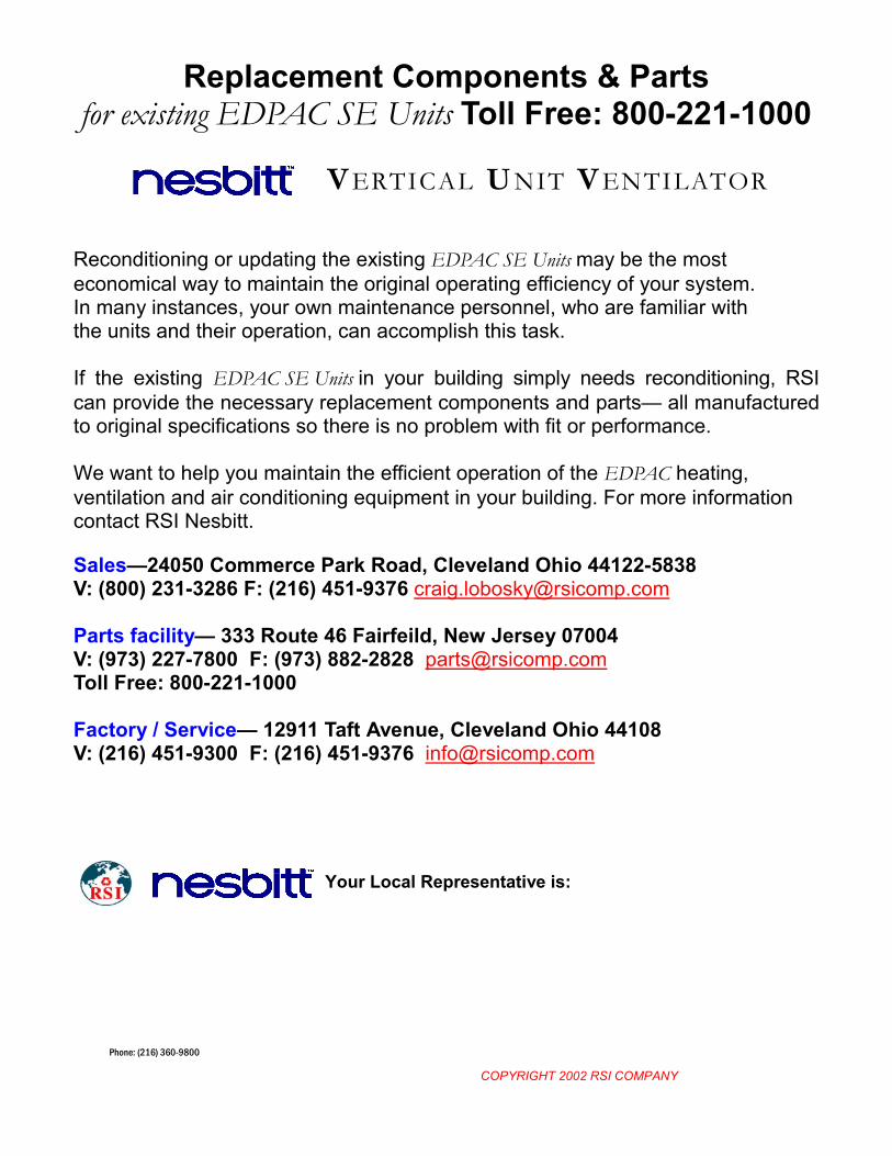
Replacement Components & Parts for existing EDPAC SE Units Toll Free: 800-221-1000
Reconditioning or updating the existing EDPAC SE Units may be the most economical way to maintain the original operating efficiency of your system. In many instances, your own maintenance personnel, who are familiar with the units and their operation, can accomplish this task. If the existing EDPAC SE Units in your building simply needs reconditioning, RSI can provide the necessary replacement components and parts— all manufactured to original specifications so there is no problem with fit or performance. We want to help you maintain the efficient operation of the EDPAC heating, ventilation and air conditioning equipment in your building. For more information contact RSI Nesbitt. Sales—24050 Commerce Park Road, Cleveland Ohio 44122-5838 V: (800) 231-3286 F: (216) 451-9376 [email protected] Parts facility— 333 Route 46 Fairfeild, New Jersey 07004 V: (973) 227-7800 F: (973) 882-2828 [email protected] Toll Free: 800-221-1000 Factory / Service— 12911 Taft Avenue, Cleveland Ohio 44108 V: (216) 451-9300 F: (216) 451-9376 [email protected]
Your Local Representative is:
VERTICAL UNIT VENTILATOR
COPYRIGHT 2002 RSI COMPANY