upper limb powered exoskeleton - bionics labbionics.seas.ucla.edu/publications/jp_15.pdfoctober 23,...
TRANSCRIPT

October 23, 2007 9:32 WSPC/191-IJHR 00114
International Journal of Humanoid RoboticsVol. 4, No. 3 (2007) 529–548c© World Scientific Publishing Company
UPPER LIMB POWERED EXOSKELETON
JACOB ROSEN∗ and JOEL C. PERRY†
Department of Electrical Engineering,University of Washington, Box 352500,Seattle, Washington, 98195-2500, USA
∗[email protected]†[email protected]
Received 8 February 2007Revised 16 March 2007
An exoskeleton is a wearable robot with joints and links corresponding to those of thehuman body. With applications in rehabilitation medicine, virtual reality simulation, andteleoperation, exoskeletons offer benefits for both disabled and healthy populations. Ana-lytical and experimental approaches were used to develop, integrate, and study a poweredexoskeleton for the upper limb and its application as an assistive device. The kinematicand dynamic dataset of the upper limb during daily living activities was one among sev-eral factors guiding the development of an anthropomorphic, seven degree-of-freedom,powered arm exoskeleton. Additional design inputs include anatomical and physiologicalconsiderations, workspace analyses, and upper limb joint ranges of motion. Proximalplacement of motors and distal placement of cable-pulley reductions were incorporatedinto the design, leading to low inertia, high-stiffness links, and back-drivable transmis-sions with zero backlash. The design enables full glenohumeral, elbow, and wrist jointfunctionality. Establishing the human-machine interface at the neural level was facilitatedby the development of a Hill-based muscle model (myoprocessor) that enables intuitiveinteraction between the operator and the wearable robot. Potential applications of theexoskeleton as a wearable robot include (i) an assistive (orthotic) device for human poweramplifications, (ii) a therapeutic and diagnostics device for physiotherapy, (iii) a hapticdevice in virtual reality simulation, and (iv) a master device for teleoperation.
Keywords: Activities of daily living; dynamics; human arm; exoskeleton; kinematics;wearable robotics.
1. Introduction
Integrating capabilities of humans and robotic-machines into a unified system offersnumerous opportunities for developing a new generation of assistive technology.Potential applications could benefit members of both healthy and disabled popula-tions. For many physical tasks, human performance is limited by muscle strength.Similarly, muscle weakness is the primary cause of disability for persons with avariety of neuromuscular diseases including stroke, spinal cord injury, muscular dys-trophies, and other neuro-degenerative disorders. Opposite this limitation in mus-cular strength, humans possess specialized and complex algorithms for control of
529

October 23, 2007 9:32 WSPC/191-IJHR 00114
530 J. Rosen & J. C. Perry
movement, involving both higher and lower neural centers. These algorithms enablehumans to perform very complicated tasks such as locomotion and arm movement,while at the same time avoid object collisions. In contrast, robotic manipulators canbe designed to perform tasks requiring large forces or moments, depending on theirstructure and on the power of their actuators. However, the control algorithms thatgovern their dynamics lack the flexibility to perform in a wide range of conditionswhile preserving the same quality of performance as humans. It seems therefore thatcombining these two entities, the human and the robot, into one integrated systemunder the control of the human, may lead to a solution which will benefit from theadvantages of each subsystem. The mechanical power of the machine, integratedwith the inherent human control system, could allow efficient performance of tasksrequiring higher forces than the human could otherwise produce. At the heart of thishuman-machine integration lie two fundamental scientific and technological issues:(i) the exoskeleton (orthotic device) mechanism itself and its biomechanical inte-gration with the human body, and (ii) the human machine interface (HMI). Thesetwo key issues will determine the quality of the integration between the human andthe exoskeleton in terms of how natural it will be for the operator to control theexoskeleton device as a biological extension of his/her body.
The exoskeleton, as an assistive device, is an external structural mechanismwith joints and links corresponding to those of the human body. The human wearsthe exoskeleton, and its actuators generate torques applied on the human joints.In utilizing the exoskeleton as a human power amplifier, the human provides con-trol signals for the exoskeleton, while the exoskeleton actuators provide most ofthe power necessary for task performance. The human becomes part of the sys-tem and applies a scaled-down force in comparison with the load carried by theexoskeleton. Using the exoskeleton as a master device in a teleoperation systemenables the operator to control a secondary, possibly remote, robotic arm (slave).In a bilateral mode, the forces applied on the remote robotic arm by the environ-ment are reflected back to the master and applied on the operator’s arm by theexoskeleton structure and actuators. In this setup, the operator feels the interac-tion of the robotic arm tool-tip with the environment.1,2 Employing the exoskeletonas a haptic device is a relatively new technology aiming to generate human inter-action with virtual objects simulated in virtual reality. As a result, virtual objectscan be touched by the operator. The exoskeleton structure and its actuators pro-vide force feedback, emulating the real object including its mechanical and textureproperties. The exoskeleton, in that sense, simulates an external environment andadds the sense of touch (haptics) to the graphical virtual environment.1,3−5 Severalmechanisms including arms,6−18 hands,19,20 legs,21−24 and other haptic devices weredeveloped for many applications.25
Throughout the last three decades, several designs of exoskeletons for humanpower amplification have been developed and evaluated. In studying the evolu-tion of these systems, two basic types with different Human Machine Interfaces

October 23, 2007 9:32 WSPC/191-IJHR 00114
Upper Limb Powered Exoskeleton 531
(HMI) seem to emerge, which may be defined as generations. The first exoskeletongeneration was developed based on the mission profile of the US Department ofDefense that defined the exoskeleton as a powered suit to augment the lifting andcarrying capabilities of soldiers. It was originally named “man-amplifier”. The pri-mary intent was to develop a system that would greatly increase the strength of ahuman operator while maintaining human control of the manipulator. The first gen-eration prototype, known as Hardiman, was the first attempt to mechanically designa man-amplifying exoskeleton using a hydraulically powered articulating frame wornby an operator.26−30 The position-controlled architecture led to poor responsive-ness and instability. The second generation of exoskeletons placed the HMI atthe dynamics level, utilizing the direct contact forces (measured by force sensors)between the human and the machine as the main command signals to the exoskele-ton. The human wore the extender, in a way that linked them together mechani-cally. The operator was in full physical contact with the exoskeleton throughout itsmanipulation.22−24,31−34 Several experimental extender prototypes were designedand built in order to study issues associated with this mode of control.
A common feature in both the first and second generation of exoskeletons wasthat the operator must apply an action, either kinematic — position command (firstgeneration) — or dynamic — contact force command (second generation) — in orderto trigger the exoskeleton response. Obviously, this sequence of events constitutesa source of delay in both systems. The inherent time delay of the physiologicalsystem when combined with the delay of the system’s mechanical actuators has adeleterious effect on overall performance. From the control theory perspective, gainand time delays are linked together. Inherent time delays in a system reduce thephase margin, and hence stability will be reduced in addition to inherently limitedbandwidth.35 Moreover, from the operational perspective, the operator feels as if theexoskeleton is following his/her limb movements rather than moving with his/herlimb synergistically. As a result of a limited operational bandwidth in these firstgenerations, the operator will not be able to act and respond quickly, for example,to catch a falling object.
Setting the HMI at higher levels of the human physiological (neurological) sys-tem hierarchy, one can overcome the electro-chemical-mechanical delay, usuallyreferred to as the electro-mechanical delay (EMD).36 This inherent time delay refersto the interval between the time when the neural system activates the muscularsystem and the time when the muscles and the associated soft tissues mechanicallycontract and generate moments around the joints. The main advantage of estab-lishing the interface at the neuromuscular level is the ability to estimate the forcesthat will be generated by the muscles, using a muscle model, before the musclecontraction actually occurs. As a result, the reaction time of the human/machinesystem should decrease, resulting in a more natural control of the task. In line withthis concept, a third generation of exoskeletons may be defined by setting the HMIat the human neuromuscular junction.

October 23, 2007 9:32 WSPC/191-IJHR 00114
532 J. Rosen & J. C. Perry
(a) (b)
(c)
Fig. 1. Three generations of upper limb exoskeletons: (a) 1-DOF exoskeleton, elbow joint,(b) 3-DOF exoskeleton — two degrees of freedom at the shoulder joint and one DOF at theelbow joint — and (c) the CADEN-7 — two exoskeleton arms (left and right arm) with sevendegrees of freedom each.
One of the principle innovative ideas of the research was setting the HMI at theneuromuscular level and utilizing processed surface electromyographic (sEMG) sig-nals as one of the primary command signals of the system (Fig. 1). The exoskeletonas an assistive device will act as a “human-amplifier” increasing the force generatedby the human muscles. As a human amplifier the exoskeleton will provide the oper-ator a scaled-down version of the external load. For example, in case of an objectmanipulation, the human may feel only 10% of the external load while the exoskele-ton carries the remaining 90% of the load. Although this general concept may beapplied to other parts of the human musculoskeletal system, the upper limb (arm)was selected for the purpose of studying the hypotheses associated with the pro-posed HMI of the exoskeleton. The upper limb is composed of segments linked byarticulations with multiple degrees of freedom and is able to perform tasks requiring
October 23, 2007 9:32 WSPC/191-IJHR 00114
Upper Limb Powered Exoskeleton 533
both power and precision of movement. From the technological perspective, an elec-tromechanical system that is fully portable is still not feasible, due to the power toweight ratio of the power source. However, for the human upper limb, portability isnot as critical of an issue as it is for the lower limb. The exoskeleton system may bepart of a stationary working station, or it could be fixed to the frame of a poweredwheelchair and powered by the wheelchair battery.
The primary hypothesis of a neural-controlled exoskeleton is that the HMI canbe set at the neuromuscular level, using processed sEMG signals as the primarycontrol signal to the exoskeleton. These signals are the same signals initiated bythe human’s central nervous system to contract the human’s own actuators (themuscles). The primary component that enables this approach is the myoprocessor.The myoprocessor is a set of computational representations (models) of the humanarm muscles running in real-time and in parallel to the physiological muscles thatpredicts joint torque.
The scope of this manuscript is to provide an overview of a research effort todevelop, integrate, and study a seven degree-of-freedom (DOF) exoskeleton and toexplore its operation as a human amplifier utilizing a neural controller.
2. Methods
Two sets of databases were collected prior to the design of the exoskeleton arm.The kinematics and the dynamics of the human arm during activities of daily liv-ing (ADL) were studied in part to define the engineering specifications for theexoskeleton arm design. In addition, the neural activities in well-structured singleand multi-joint arm activities, under various loading conditions, were studied inorder to develop muscle models (myoprocessor) that further enable development ofthe neural-control approach of the exoskeleton.
2.1. Human arm kinematics — Experimental protocol
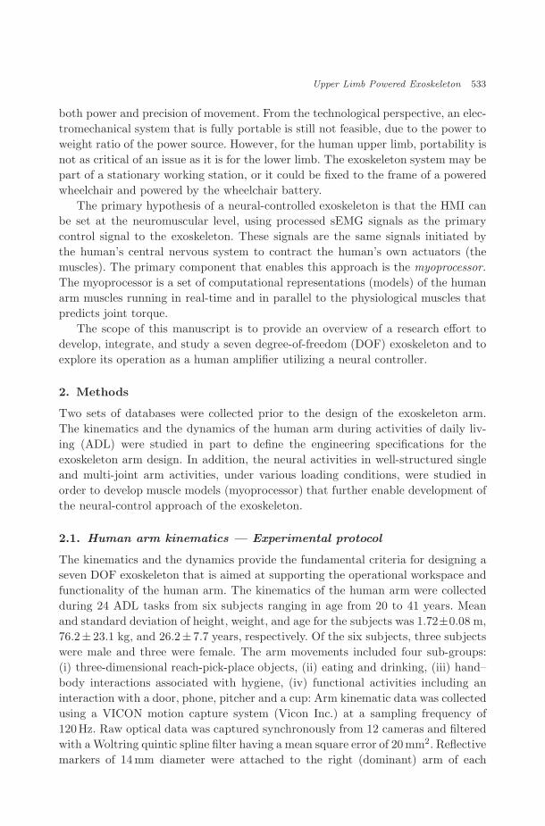
The kinematics and the dynamics provide the fundamental criteria for designing aseven DOF exoskeleton that is aimed at supporting the operational workspace andfunctionality of the human arm. The kinematics of the human arm were collectedduring 24 ADL tasks from six subjects ranging in age from 20 to 41 years. Meanand standard deviation of height, weight, and age for the subjects was 1.72±0.08 m,76.2± 23.1 kg, and 26.2± 7.7 years, respectively. Of the six subjects, three subjectswere male and three were female. The arm movements included four sub-groups:(i) three-dimensional reach-pick-place objects, (ii) eating and drinking, (iii) hand–body interactions associated with hygiene, (iv) functional activities including aninteraction with a door, phone, pitcher and a cup: Arm kinematic data was collectedusing a VICON motion capture system (Vicon Inc.) at a sampling frequency of120Hz. Raw optical data was captured synchronously from 12 cameras and filteredwith a Woltring quintic spline filter having a mean square error of 20mm2. Reflectivemarkers of 14mm diameter were attached to the right (dominant) arm of each

October 23, 2007 9:32 WSPC/191-IJHR 00114
534 J. Rosen & J. C. Perry
(a) (b) (c)
Fig. 2. Human arm kinematics — Experimental setup: (a) Reflective markers attached to the upperarm; (b) subject sitting at the table setup performing a reach-pick-place action; (c) human armjoints, links, and coordinate assignment for the Vicon system (Human model from Bodyworks —Zetec, Ltd. Inc).
subject at seven key anatomical locations (Fig. 2). Individual models and markersets were calibrated for each subject and further used during Vicon post-processingof subject data.
A seven DOF model of the human arm was developed including three segments(upper arm, lower arm, and hand) connected to each other and the human trunkwith a frictionless ball-and-socket shoulder joint, two-axis elbow, and two-axis wrist.Using this model, seven equations of motion were derived. The mass, the center ofmass location, and the inertia of the human arm segments were estimated for eachsubject. The general form of the equations of motion is expressed in Eq. (1).
τ = M(Θ)Θ̈ + V (Θ, Θ̇) + G(Θ), (1)
where M(Θ) is the 7 × 7 mass matrix, V (Θ, Θ̇) is a 7 × 1 vector of centrifugal andCoriolis terms, G(Θ) is a 7×1 vector of gravity terms, and τ is a 7×1 vector of thenet torques applied at the joints. Given the kinematics of the human arm (Θ̈, Θ̇, Θ)the individual contributions on the net joint toque (τ) vector were calculated foreach action of each subject. These allow one to examine the contribution of theindividual components (inertial, centrifugal, and Coriolis, and gravity) to the nettorque.
2.2. Exoskeleton arm — Design methodology
Two exoskeleton arms were developed, each including seven degrees of freedom(DOFs). Each exoskeleton arm is actuated by seven DC brushed motors (Maxon)that transmit the appropriate torque to each joint utilizing a cable-based transmis-sion system. Four force/torque sensors (ATI Industrial Automation) are located at
October 23, 2007 9:32 WSPC/191-IJHR 00114
Upper Limb Powered Exoskeleton 535
all interface elements between the human arm and exoskeleton as well as betweenthe exoskeleton and external load, measuring all forces and torques acting and react-ing between the human arm, the external load, and the exoskeleton [Fig. 1(c)]. Themechanisms are attached to a frame mounted on the wall, which allows both heightand distance between the arms to be adjusted.
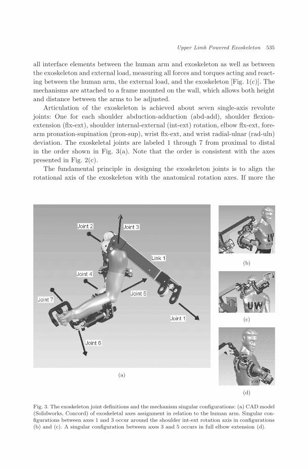
Articulation of the exoskeleton is achieved about seven single-axis revolutejoints: One for each shoulder abduction-adduction (abd-add), shoulder flexion-extension (flx-ext), shoulder internal-external (int-ext) rotation, elbow flx-ext, fore-arm pronation-supination (pron-sup), wrist flx-ext, and wrist radial-ulnar (rad-uln)deviation. The exoskeletal joints are labeled 1 through 7 from proximal to distalin the order shown in Fig. 3(a). Note that the order is consistent with the axespresented in Fig. 2(c).
The fundamental principle in designing the exoskeleton joints is to align therotational axis of the exoskeleton with the anatomical rotation axes. If more the
(a)
(b)
(c)
(d)
Fig. 3. The exoskeleton joint definitions and the mechanism singular configurations: (a) CAD model(Solidworks, Concord) of exoskeletal axes assignment in relation to the human arm. Singular con-figurations between axes 1 and 3 occur around the shoulder int-ext rotation axis in configurations(b) and (c). A singular configuration between axes 3 and 5 occurs in full elbow extension (d).

October 23, 2007 9:32 WSPC/191-IJHR 00114
536 J. Rosen & J. C. Perry
one axis is involved at a particular anatomical joint (e.g. the shoulder and wrist),the exoskeleton joints emulating the anatomical joint intersect at the center ofthe anatomical joint. Consistent with other work, the glenohumeral (G-H) joint ismodeled as a spherical joint composed of three intersecting axes.37 The elbow ismodeled by a single axis orthogonal to the third shoulder axis, with a joint stoppreventing hyperextension. Exoskeletal prono-supination takes place between theelbow and wrist joints as it does in the physiological mechanism. And finally, twointersecting orthogonal axes represent the wrist. Comparing the range of motion ofthe anatomical joints in the ADL study and the range of motion of the exoskeletonshows that the exoskeleton’s joints support 99% of the ranges of motion requiredto perform daily activities.
Upper arm and forearm rotations present special challenges in design as a resultof the human arm occupying a large volume along the joint axis of rotation. Thisspace, which in classical robotics would be occupied by mechanical joints, must bekept not only clear of obstacles but also of component configurations that couldresult in injury or discomfort to the user, such as sharp edges or pinch points.Semi-circular bearings, achieving a laterally-open interface, were used to allow usersto don the device without strain or discomfort. On the adjacent link distal tothese semi-circular axes, the mechanical components of the HMI are mounted. Themechanical HMI (mHMI), as opposed to the neural HMI, consists of a pressure-distributive structural pad that is rigidly mounted to a six-axis force/torque sensorand simultaneously securely strapped to the mid-distal portion of each respectivearm segment.
The open design of the mHMI is a beneficial feature in assistive applications withmobility-impaired users, but the attachment of the interface itself is most critical.The assumption that the human arm can be represented as a seven DOF systemis an assumption pertaining to skeletal and end-effector biomechanics. Componentssuch as skin, musculature, and other soft tissues cannot be represented by a modelas simple as a similar seven DOF representation. This is a significant observationgiven that most exoskeleton research, including the research presented in this text,uses non-invasive techniques for the mHMI. All non-invasive interfaces will haveimperfections that are influenced by the selection of interfacial size, position, andorientation. mHMIs that are placed excessively high (proximal) on the arm, mayproduce unnecessarily large forces, and potential discomfort to the user, throughthe interface points when operated in an assistive mode. Additionally, complianceof relaxed musculature in proximal regions of the limb, as well as non-uniformtransformations during muscular contraction, reduce interfacial stiffness and pro-duce higher non-linear disturbances in force measurement, which would ultimatelyresult in reduced bandwidth of performance. Cross-sections of distal parts of limbsegments are less variable in magnitude and experience fewer underlying skeletaltransformation, making them better apt for mHMI attachment.

October 23, 2007 9:32 WSPC/191-IJHR 00114
Upper Limb Powered Exoskeleton 537
Another significant consideration in exoskeleton design is placement of singu-larities. A singularity is a device configuration where a DOF is lost or compro-mised as a result of alignment of two rotational axes. The fundamental principlein addressing the singularity of the exoskeleton is, if possible, to place singularconfigurations, through joint design, outside or at the edge of the anthropomet-ric reachable workspace of the human arm. For the exoskeleton arm, singulari-ties occur when joints 1 and 3 or joints 3 and 5 align [Figs. 3(b) and 3(c)]. Thesingularity between joints 3 and 5 naturally occurs only in full elbow extension,i.e. on the edge of the forearm workspace [Fig. 3(d)]. Each of these singular con-figurations take place at or near the edge of the human workspace leaving themajority of the workspace free of singularities. Moreover, for optimal ease of move-ment in any direction, singular axes should be placed orthogonal to directionswhere isotropy is of highest importance. For the singularity placement shown inFig. 3, isotropy will be maximized at 42.5◦ of shoulder flexion and 26.4◦ of shoul-der abduction, values that lie in the median of shoulder ROM based on the ADLstudy.
In the field of wearable robotics, weight is a critical factor that frequentlymust be sacrificed for the sake of strength or rigidity. However, development ofa rigid structure that lacks adequate bandwidth is as ineffective of a tool as onethat is lightweight but lacks structural rigidity. To achieve both rigidity and band-width, critical decisions were made regarding transmission type and placement ofactuators.
Placing the motors, the heaviest components in the exoskeleton system, has asignificant impact on the overall performance of the system and the quality of itsinteraction with the human operator. Motors for joints 1–4 were mounted on thestationary base, achieving a 60% reduction in overall weight of the moving parts.The remaining three motors, whose torque requirements are substantially less, werepositioned on the forearm. As each motor carries the weight and inertia of themore distally placed motors, the importance of high power-to-weight ratio increasesfrom shoulder to wrist. Shoulder and elbow joints are each driven by a high torque,low power-to-weight motor (6.23 Nm, 2.2 Nm/kg), while wrist joints are driven bya lower torque, high power-to-weight motor (1.0 Nm, 4.2 Nm/kg). The primaryadvantage of using cable drive transmissions lies in their ability to transmit loadsover long distances without the friction or backlash inherent to gears. The absenceof backlash is achieved through the structural continuity of the cable, enabling adirect link between the driving shaft and the shaft or link being driven. Cable-driven systems, including one stage of speed reduction for joints 5–7 and two stagesof speed reduction for joints 1–4, were developed and integrated to transmit torquesfrom the actuators to the various joints.38 An I-beam cross section shape was usedfor all the links allowing bilateral cable routing, as well as high structural stiffnessand appropriate strength.

October 23, 2007 9:32 WSPC/191-IJHR 00114
538 J. Rosen & J. C. Perry
2.3. The myoprocessor and neural control
Two basic conditions have to be fulfilled in order to establish an HMI at the neuro-muscular junction. The first condition is the capability to measure the bio-signals(myosignal intentions of muscles contraction) involved in the joint’s movement,which can be measured using surface electrodes, a non-invasive technique. The sec-ond condition is the ability to simulate and to predict the functions of the humanbody’s subsystems and organs from the interface level (myosignals) down to thelower levels of the physiological hierarchy (skeletal muscle forces and moments).The term “myoprocessor” is used to define the component of the system that simu-lates the human skeletal muscles behavior and provides an estimation of the muscleforces.39 The myoprocessor runs in real-time and in parallel to the physiologicalmuscles.
During the electro-chemical-mechanical time delay (EMD), the system gath-ers information regarding the physiological muscle’s neural activation level basedon processed EMG signals, the joint positions, and joint angular velocities. Thisinformation is fed into a myoprocessor, which in turn predicts the moments thatare going to be developed by the physiological muscles relative to each joint. Thepredicted moments are fed to the exoskeleton system such that by the time thephysiological muscle contracts, the exoskeleton has amplified the joint moment bya pre-selected gain factor and assisted the movement. Part of the time gained byusing these predicted muscle forces is employed by the electromechanical subsys-tems of the powered exoskeleton to compensate for their own inherent reaction time.Figure 4 depicts the fundamental building block of setting the HMI at the neurallevel. The main advantage of establishing the interface at the neuromuscular levelis the ability to estimate the forces that will be generated by the muscles before themuscle contraction actually occurs. This concept takes advantage of the inherentdelay (EMD) of the musculoskeletal system. The EMD refers to the interval of timebetween neural activation of the muscular system and the generation of momentsaround the joint from the mechanical contraction of musculature and associatedsoft tissue [Fig. 4(b)].
Hill based muscle models (myoprocessor) were developed as the core componentof the exoskeleton control algorithm. The performance evaluation of the myoproces-sor was based on a database that experimentally collected input/output signals ofthe myoprocessor. The experimental setup included passive weight lifting machinesthat were used for single and multiple upper arm joint movements. The data col-lection included the joint kinematics and dynamics in addition to sEMG signalscollected simultaneously from 28 muscles at 1KHz (Fig. 5) under various load-ing conditions (25%, 50%, and 75% of the maximal isometric loading condition).Two types of models were developed and analyzed: (i) Hill based models39,40 and(ii) Neural Networks.40 Genetic algorithms were further used to tune the internalparameters of the Hill-based model that predicted the joint torque within a varianceof 15% of the nominal value.

October 23, 2007 9:32 WSPC/191-IJHR 00114
Upper Limb Powered Exoskeleton 539
(a)
(b)
Fig. 4. The myoprocessor: (a) low-level block diagram of a hill-based muscle model, and (b) system-level block diagram of neural control scheme for the exoskeleton system.
2.4. Exoskeleton performance evaluation protocol
The exoskeleton performance was previously conducted in static and dynamic con-ditions with a fixed external load.41 The current experimental protocol focused onthe exoskeleton performance evaluation under dynamic loading conditions that wereunpredictable from the operator’s perspective. These loading conditions were sim-ulated by generating sudden changes in the external load. The subject was wearingthe exoskeleton in a standing posture with his arm fully stretched and perpendicular

October 23, 2007 9:32 WSPC/191-IJHR 00114
540 J. Rosen & J. C. Perry
Fig. 5. Experimental setup for measuring neural activity (sEMG) along with the kinematics anddynamics of selected arm activities (e.g. flexion and extension of the elbow) under various loadingconditions.
to the ground. The exoskeleton operator was instructed to generate a full elbow flex-ion movement followed by a full elbow extension while caring an external load of1 kg. When the elbow angle reached 90◦, an additional external mass of 1.265kg wasadded to the exoskeleton. As a result, in the elbow joint angular range of 0–90◦, theexternal exoskeleton load was 1 kg and in the angular range of 90–150◦ the externalload was 2.265kg. The mass was added during the flexion movement and releasedduring the extension movement at the elbow joint angle of 90◦.
3. Results
3.1. Human arm kinematics
The statistical distribution of the human arm kinematics, collected experimentallyduring ADL’s, along with the dynamics calculated based on the analytical model aresummarized in Fig. 6. The kinematics and the dynamics of the arm while perform-ing a functional arm reach task are plotted in Fig. 6(a). The last row of Fig. 6(a)depicts, for each joint, the total joint axis torque as well as the gravitational termsand the inertial, centrifugal, and Coriolis terms combined. In general, the magni-tude of joint torque is small for the distal joint and higher for the proximal joints.Regardless of the joint location, the joint torque component that compensates thegravitational loads is significantly larger than the inertial, centrifugal, and Coriolisterms combined.
In fact, the overall shape of the joint axis torque during the selected daily activ-ities is dictated solely by the low frequency gravitational term. This phenomenonwas observed in all the actions included in the ADL database that were collected in

October 23, 2007 9:32 WSPC/191-IJHR 00114
Upper Limb Powered Exoskeleton 541
(a)
(b) (c)
Fig. 6. Kinematic and dynamic data of the human arm during ADL’s: (a) Time histories of the jointangles and the net joint torques during a functional arm reach motion (opening a cupboard door),where joint torques (τ) are separated into total torque (solid), torque due to gravity (dotted), andtorque due to inertial, Coriolis and centrifugal effects (dashed); statistical distribution of (b) jointangles and (c) joint torques are displayed as histograms, plotted sequentially from the top as Viconaxes 1 through 7. Zero position of the arm shown in Fig. 2(c).
this study. Identifying the joint torque component due to gravitational loads as thelargest component provides the justification for incorporating a gravity compensa-tion algorithm not just for the exoskeleton alone but for the human operator armas well as part of the control algorithm of the system.

October 23, 2007 9:32 WSPC/191-IJHR 00114
542 J. Rosen & J. C. Perry
While some distributions appear normal in shape, others possess a bi-modalor even tri-modal form where modal centers correspond to key anthropomorphicconfigurations [Figs. 6(b) and 6(c)]. These configurations are positions of the armthat occur commonly throughout daily activities, often where joint velocities arelow at the initial or final periods of motion trajectories.
3.2. Exoskeleton performance
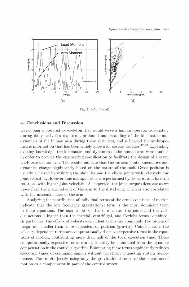
The data collected experimentally under dynamic and unpredictable loading condi-tions indicate a natural and stable movement of the integrated human/exoskeletonsystem (Fig. 7). The EMG signals and the activation levels of the Biceps Brachii(BIC) and the Triceps Brachii (TRI) muscles [Fig. 7(a)] show a high level of activityduring the two transient periods of increasing and decreasing the load. The levelof muscle activity is higher during the process of decreasing the load in both theBIC and the TRI muscles. Those high muscle activation levels are accompaniedwith velocity decrease during the elbow flexion movement, aimed to preserve stablesmooth movement in inertial transient processes [Fig. 7(b)]. The dynamic loadingtransient process appears as a spike phenomenon in both the human arm and theload moments [Fig. 7(c)] indicating the sudden increase/decrease of the load duringthe flexion/extension movement, respectively. The exoskeleton gain is constant dur-ing the elbow flexion/extension movement; however, it tends to change in a boundedrange during transient loading phenomena [Fig. 7(d)]. The straight line in Fig. 7(d)represents a constant mechanical gain. The 45◦ inclination of the line represents amechanical gain of one (non-assistive mode of the exoskeleton).
0 5 10 15 20 25 30-500
0
500
BIC
EM
G
0 5 10 15 20 25 300
0.1
0.2
BIC
Act
ivat
ion
0 5 10 15 20 25 30-500
0
500
TRI E
MG
0 5 10 15 20 25 300
0.1
0.2
Time [s]
TRI A
ctiv
atio
n
0 5 10 15 20 25 300
1
2
3
Ang
le [r
]
0 5 10 15 20 25 30-2
0
2
Vel
ocity
[r/s
]
0 5 10 15 20 25 30-5
0
5
Time [s]
Acc
eler
atio
n [r/
s^2]
(a) (b)
Fig. 7. Exoskeleton operational performance in unpredicted, dynamic loading conditions: (a) rawEMG signals and muscle activation levels of the Biceps Brachii (top) and the Triceps Brachii(bottom); (b) elbow joint kinematics; (c) arm and external load moments about the elbow joint,where the difference between the two moments is generated by the exoskeleton; (d) external loadmoment as a function of the human arm moment.
October 23, 2007 9:32 WSPC/191-IJHR 00114
Upper Limb Powered Exoskeleton 543
0 5 10 15 20 25 300
5
10
15
20
25
Time [s]
Mom
ent [
Nm
]
Load Moment
Arm Moment
0 5 10 15 20 250
5
10
15
20
25
Arm Moment [Nm]
Load
Mom
ent [
Nm
]
(c) (d)
Fig. 7. (Continued)
4. Conclusions and Discussion
Developing a powered exoskeleton that would serve a human operator adequatelyduring daily activities requires a profound understanding of the kinematics anddynamics of the human arm during these activities, and is beyond the anthropo-metric information that has been widely known for several decades.42,43 Expandingexisting knowledge, the kinematics and dynamics of the human arm were studiedin order to provide the engineering specification to facilitate the design of a sevenDOF exoskeleton arm. The results indicate that the various joints’ kinematics anddynamics change significantly based on the nature of the task. Gross position isusually achieved by utilizing the shoulder and the elbow joints with relatively lowjoint velocities. However, fine manipulations are performed by the wrist and forearmrotations with higher joint velocities. As expected, the joint torques decrease as wemove from the proximal end of the arm to the distal end, which is also correlatedwith the muscular mass of the arm.
Analyzing the contribution of individual terms of the arm’s equations of motionindicate that the low frequency gravitational term is the most dominant termin these equations. The magnitudes of this term across the joints and the vari-ous actions is higher than the inertial, centrifugal, and Coriolis terms combined.In particular, the effects of velocity-dependent terms are commonly two orders ofmagnitude smaller than those dependent on position (gravity). Coincidentally, thevelocity-dependent terms are computationally the most expensive terms in the equa-tions of motion, contributing more than half of the total execution time. Thesecomputationally expensive terms can legitimately be eliminated from the dynamiccompensation in the control algorithm. Eliminating these terms significantly reducesexecution times of command signals without negatively impacting system perfor-mance. The results justify using only the gravitational terms of the equations ofmotion as a compensator in part of the control system.

October 23, 2007 9:32 WSPC/191-IJHR 00114
544 J. Rosen & J. C. Perry
The seven DOF exoskeleton design that followed the study of the kinematicsand the dynamics of the arm in ADL’s relied heavily on its findings to provide therequired engineering specifications. Additionally, principles of physiological jointsassisted in achieving a relatively lightweight, high-performance system facilitat-ing full-workspace and ROM, as defined by the ADL study. Proximal placement ofmotors, distal placement of pulley reductions, and open mechanical human-machine-interfaces were incorporated into the design of the exoskeleton. Additional charac-teristics include low inertias, high-stiffness links, and back-drivable transmissionswithout backlash.
The HMI is one of the key factors in creating an exoskeleton that is perceivedand controlled by the operator as a natural extension of his/her own body. It isa point of the integrated human machine system in which energy and informationare exchanged between the two subsystems. The HMI may include two types ofinterfaces that can, in part, merge into a single bioport: (i) the mechanical portwhich serves as the physical interface between the human body and the exoskele-ton system, and (ii) the information port which generates the command signals forthe exoskeleton by the operator. Following biomechanic and anthropometric prin-ciples led to an exoskeleton design that is compatible with the human anatomy.The mechanical design therefore satisfies the requirements for the mechanical port.Setting the information port at the neural level aims to use the same control signalsthat are used by the human body for controlling the exoskeleton subsystems. Theoptimal location of the information port at the neural hierarchy is still an openscientific question. A low-level bioport, such as invasive or non-invasive electrodescollecting neural or myosignals (EMG), utilizes a muscle-modeling approach andtakes advantage of the inherent electromechanical delay to predict the physiologi-cal muscle response. A high-level bioport, such as invasive neural signals collecteddirectly from the motor cortex or a non-invasive approach utilizing EEG signals,relies on the plasticity of the motor cortex to learn and adjust its command signalswhile avoiding the profound complexity involved in understanding the function ofthe neural system. There is no doubt that as research progresses in the biocom-patibility of invasive neural electrodes, coupled with a deeper understanding of theneural system, more viable bioport will emerge for a superior HMI.
From the electromechanical perspective, both relatively high torque-to-weightratio motors as well as the energy density of the exoskeleton energy source are themajor limiting factors in developing portable exoskeleton system. It is recognizedthat in the case of a lower limb exoskeleton, the weight of the power source, as well asthe actuators and structure, is transmitted to the ground without loading the humanbody, and therefore may overcome, in part, this technological deficiency. However,the functionality of an upper limb exoskeleton must be significantly compromisedif the aim is to make the system completely portable.
The proposed myoprocessor enables a neural interface between the human oper-ator and the exoskeleton system. This neural interface contributes to a naturaland stable integration between the wearable robot and its operator such that the

October 23, 2007 9:32 WSPC/191-IJHR 00114
Upper Limb Powered Exoskeleton 545
operator views the exoskeleton as an intuitive extension of his/her body. Fur-ther exploration of the myoprocessor and automatic adjustment of its internalparameters based on patient data will continue to be an active field of research.Using the exoskeleton as a human assistive device remains one among many poten-tial applications of the system, including automatic physiotherapy, utilization as ahaptic device for interaction with virtual objects in a virtual environment, or as amaster device for teleoperation with force-feedback capabilities.
References
1. B. Hannaford, Feeling is believing: Haptics and telerobotics technology, in The Robotin the Garden: Telerobotics and Telepistemology in the Age of the Internet, ed. J. K.Goldberg (MIT Press, Cambridge, MA, 2000).
2. S. C. Jacobsen, F. M. Smith, D. K. Backman and E. K. Iversen, High performance,high dexterity, force reflective teleoperator, in Proc. 38th Int. Conf. Remote SystemsTechnology, Washington DC (1990), pp. 180–185.
3. B. Hannaford and S. Venema, Kinesthetic display for remote and virtual environment,in Virtual Environment and Advanced Interface Design, eds. W. Barfield and T. A.Furness (Oxford University Press, Oxford, 1995), pp. 415–436.
4. J. M. Hollerbach and S. C. Jacobsen, Haptic interfaces for teleoperation and virtualenvironments, in 1st Workshop on Simulation and Interaction in Virtual Environ-ments, Iowa City, IA (1995).
5. G. C. Burdea, Force and Touch Feedback for Virtual Reality (John Wiley & Sons,New York, 1996), pp. 339.
6. B. M. Jau, Anthropomorhic exoskeleton dual arm/hand telerobot controller, in IEEEInt. Workshop on Intelligent Robots and Systems (IROS), Tokyo, Japan (IEEE Press,1988), pp. 715–718.
7. F. P. Brooks Jr., M. Ouh-Young, J. J. Batter and P. J. Kilpatrick, Project GROPE— Haptic displays for scientific visualization, Comput. Graph. 24(4) (1990) 177–185.
8. M. Bergamasco, B. Allotta, L. Bosio, L. Ferretti, G. Parrini, G. M. Prisco, F. Salsedoand G. Sartini, An arm exoskeleton system for teleoperation and virtual environmentsapplications, in IEEE Int. Conf. Robotics and Automation (ICRA), San Diego, USA,Vol. 2 (IEEE Press, 1994), pp. 1449–1454.
9. D. G. Caldwell, O. Kocak and U. Andersen, Multi-armed dexterous manipulator oper-ation using glove/exoskeleton control and sensory feedback, in IEEE/RSJ Int. Conf.Intelligent Robots and Systems (IROS), “Human Robot Interaction and CooperativeRobots”, Pittsburgh, USA, Vol. 2 (IEEE Press, 1995), pp. 567–572.
10. D. W. Repperger, B. O. Hill, C. Hasser, M. Roark and C. A. Phillips, Human trackingstudies involving an actively powered augmented exoskeleton, in IEEE 15th SouthernBiomedical Engineering Conf., Dayton, USA (IEEE Press, 1996), pp. 28–31.
11. Y. Umetani, Y. Yamada, T. Morizono, T. Yoshida and S. Aoki, “Skil Mate” wearableexoskeleton robot, in IEEE Int. Conf. Systems, Man, and Cybernetics (SMC), Tokyo,Japan, Vol. 4 (IEEE Press, 1999), pp. 984 –988.
12. L. Sooyong, L. Jangwook, C. Woojin, K. Munsang, L. Chong-Won and P. Mignon,A new exoskeleton-type masterarm with force reflection: Controller and integration, inIEEE/RSJ Int. Conf. Intelligent Robots and Systems (IROS), Kyongju, South Korea,Vol. 3 (IEEE Press, 1999), pp. 1438–1443.
13. L. Sooyong, L. Jangwook, C. Woojin, K. Munsang and L. Chong-Won, A new master-arm for man-machine interface, in IEEE Int. Conf. Systems, Man, and Cybernetics(SMC), Tokyo, Japan, Vol. 4 (IEEE Press, 1999), pp. 1038–1043.
October 23, 2007 9:32 WSPC/191-IJHR 00114
546 J. Rosen & J. C. Perry
14. A. Frisoli, F. Rocchi, S. Marcheschi, A. Dettori, F. Salsedo and M. Bergamasco,A new force-feedback arm exoskeleton for haptic interaction in virtual environments,in Proc. 1st Joint Eurohaptics Conf. and IEEE Symp. Haptic Interfaces for VirtualEnvironment and Teleoperator Systems, Pisa, Italy (IEEE Press, 2005).
15. C. Carignan, M. Liszka and S. Roderick, Design of an exoskeleton with scapula motionfor shoulder rehabilitation, in IEEE Int. Conf. Advanced Robotics (ICAR), Seattle,USA (IEEE Press, 2005), pp. 524–531.
16. K. Kiguchi, T. Tanaka, K. Watanabe and T. Fukuda, Exoskeleton for human upper-limb motion support, in IEEE Int. Conf. Robotics and Automation (ICRA), Taipei,Taiwan (IEEE Press, 2003), pp. 2206–2211.
17. G. N. Tsagarakis and D. G. Caldwell, Development and control of a “Soft-Actuated”exoskeleton for use in physiotherapy and training, Autonom. Robots 15(1) (2003)21–33.
18. M. Mihelj, T. Nef and R. Riener, ARMin — Toward a six doF upper limb rehabilita-tion robot, in IEEE/RAS-EMBS Int. Conf. Biomedical Robotics and Biomechatronics(BioRob), Pisa, Italy (IEEE Press, 2006).
19. P. Brown, D. Jones, S. K. Singh and J. M. Rosen, The exoskeleton glove for controlof para-lyzed hands, in IEEE Int. Conf. Robotics and Automation (ICRA), Atlanta,USA, Vol. 1 (IEEE Press, 1993), pp. 642–647.
20. B. M. Jau, Dexterous telemanipulation with four fingered hand system, in IEEE Int.Conf. Robotics and Automation (ICRA), Nagoya, Japan, Vol. 1 (IEEE Press, 1995),pp. 338–343.
21. D. P. Ferris, J. M. Czerniecki and B. Hannaford, An ankle-foot orthosis powered byartificial pneumatic muscles, Appl. Biomech. 21 (2005) 189–197.
22. A. Zoss, H. Kazerooni and A. Chu, On the biomechanical design of the Berkeley lowerextremity exoskeleton (BLEEX), IEEE/ASME Trans. Mechatron. 11(2) (2006).
23. H. Kazerooni and R. Steger, The Berkeley lower extremity exoskeletons, ASME J.Dynam. Syst. Measure. Cont. 128 (2006).
24. H. Kazerooni, R. Steger and L. Huang, Hybrid control of the Berkeley lower extremityexoskeleton, Int. J. Robot. Res. 25(5–6) (2006).
25. E. Guizzo and H. Goldstein, IEEE Spectrum (October, 2005).26. R. S. Mosher, Force reflecting electrohydraulic servo manipulator, Electro-Tech. 138
(1960).27. General Electric Company, Exoskeleton prototype project, final report on phase I,
Report S-67-1011, Schenectady, New York (1966).28. General Electric Company, Hardiman I prototype project, special interim study,
Report S-68-1060, Schenectady, New York (1968).29. B. J. Makinson, Research and development prototype for machine augmentation of
human strength and endurance, Hardiman I project, Report S-71-106, GE Company,Schenectady, New York (1971).
30. P. Rabischong, Robotics for the handicapped, in Proc. IFAC Control Aspects of Pros-thetics and Orthotics (IFAC), Columbus, OH (May 1982), pp. 163–167.
31. H. Kazerooni and H. Ming-Gau, The dynamics and control of a haptic interface device,IEEE Trans. Robot. Autom. 10(4) (1994) 453–464.
32. H. Kazerooni and T. J. Snyder, Case study on haptic devices: Human-inducedinstability in powered hand controllers, J. Guid. Contr. Dynam. 18(1) (1995)108–113.
33. H. Kazerooni, The human amplifier technology at the University of California,Berkeley, Robot. Autonom. Syst. 19 (1996) 179–187.

October 23, 2007 9:32 WSPC/191-IJHR 00114
Upper Limb Powered Exoskeleton 547
34. T. J. Snyder and H. Kazerooni, A novel material handling system, in IEEE Int.Conf. Robotics and Automation (ICRA), Minneapolis, USA (IEEE Press, April 1996),pp. 1147–1152.
35. G. F. Franklin, J. D. Powell and M. L. Workman, Digital Control of Dynamic Systems,3rd edn. (Addison-Wesley, Menlo Park, USA, 1998).
36. D. A. Winter, Biomechanics and Motor Control of Human Movement, 2nd edn.(John Wiley & Sons, New York, 1992).
37. B. A. Garner and M. G. Pandy, A kinematic model of the upper limb based on thevisible human project (VHP) image dataset, Computer Methods in Biomechanics andBiomedical Engineering, Vol. 2 (1999), pp. 107–124.
38. J. C. Perry and J. Rosen, Design of a 7 degree-of-freedom upper-limb poweredexoskeleton, in IEEE/RAS-EMBS Int. Conf. Biomedical Robotics and Biomechatron-ics (BioRob), Pisa, Italy (IEEE Press, 2006).
39. E. Cavallaro, J. Rosen, J. C. Perry and S. P. Burns, Myoprocessor for neural controlledpowered exoskeleton arm, IEEE Trans. Biomed. Eng. 53(11) (2006) 2387–2396.
40. J. Rosen, M. B. Fuchs and M. Arcan, Performances of Hill-type and neural networkmuscle models — Towards a myosignal based exoskeleton, Comput. Biomed. Res.32(5) (1999) 415–439.
41. J. Rosen, M. Brand, M. Fuchs and M. Arcan, A myosignal-based powered exoskeletonsystem, IEEE Trans. Syst. Man Cybern. A 31(3) (2001) 210–222.
42. Military Handbook Anthropometry of US Military Personal, DOD-HDBK-747A(1991).
43. Investigation of Internal Properties of the Human Body, DOT HS-801 430 (1975).
Jacob Rosen (M’01) received his B.Sc. degree in MechanicalEngineering and M.Sc. and Ph.D. degrees in Biomedical Engi-neering from Tel-Aviv University, Tel-Aviv, Israel, in 1987, 1993and 1997, respectively. From 1993 to 1997, he was a ResearchAssociate developing and studying the myosignal based pow-ered exoskeleton at the Biomechanics Laboratory, Departmentof Biomedical Engineering, Tel-Aviv University. During the sameperiod of time he held a Biomechanical Engineering position in
a startup company developing innovative orthopedic spine/pelvis implants. Since1997, he has been at the University of Washington, Seattle, currently as a ResearchAssociate Professor of Electrical Engineering with adjunct positions in the Depart-ments of Surgery and Mechanical Engineering. His research interests focus onsurgical robotics, wearable robotics (exoskeleton) biorobotics, biomechanics, andhuman-machine interface.
October 23, 2007 9:32 WSPC/191-IJHR 00114
548 J. Rosen & J. C. Perry
Joel C. Perry was born in 1978 in Bellingham, WA. He receivedhis B.Sc. degree from Gonzaga University in 2000, and M.Sc.and Ph.D. degrees from the University of Washington, Seattle,in 2002 and 2006, both in Mechanical Engineering. From 2000 to2002, he was a Research Assistant developing a powered prosthe-sis at the VA hospital, Seattle. Since 2002, he has been develop-ing an anthropomorphic powered exoskeleton at the BioroboticsLaboratory, Department of Electrical Engineering, University of
Washington. His research interests include medical device development, rehabilita-tion robotics, and assistive technologies for the disabled.