design and control of a lower limb exoskeleton for robot-assisted gait...
TRANSCRIPT
Applied Bionics and BiomechanicsVol. 6, No. 2, June 2009, 229–243
Design and control of a lower limb exoskeleton for robot-assisted gait training
Pieter Beyl∗, Michael Van Damme, Ronald Van Ham, Bram Vanderborght and Dirk Lefeber
Department of Mechanical Engineering, Vrije Universiteit Brussel, Brussels, Belgium
(Received 30 September 2008; final version received 23 January 2009)
Robot-assisted rehabilitation of gait still faces many challenges, one of which is improving physical human-robot interaction.The use of pleated pneumatic artificial muscles to power a step rehabilitation robot has the potential to meet this challenge.This paper reports on the development of a gait rehabilitation exoskeleton with a knee joint powered by pleated pneumaticartificial muscles. It is intended as a platform for the evaluation of design and control concepts in view of improved physicalhuman-robot interaction. The design was focused on the optimal dimensioning of the actuator configuration. Safety beingthe most important prerequisite, a proxy-based sliding mode controller (PSMC) was implemented as it combines accuratetracking during normal operation with a smooth, slow and safe recovery from large position errors. Treadmill walkingexperiments of a healthy subject wearing the powered exoskeleton show the potential of PSMC as a safe robot-in-chargecontrol strategy for robot-assisted gait training.
Keywords: robot-assisted gait rehabilitation; powered exoskeleton; compliant actuator; proxy-based sliding mode control
1. IntroductionLocomotion training is considered an effective approach tohelping incomplete spinal cord injured (SCI) subjects re-cover their walking capabilities (Wernig and Muller 1992;Wirz et al. 2001). The automation of locomotion trainingby means of a powered exoskeleton potentially improvestraining efficacy and rehabilitation outcome (Krebs et al.2000; Colombo et al. 2001). Physiological gait patterns canbe produced and adapted with higher accuracy. Automaticmonitoring of the patient’s progress allows the developmentof more adequate training schemes. The robotic device re-lieves strain on therapists, thus enabling longer trainingsessions and allowing the same number of therapists tosupervise more patients.
Several research groups are developing powered ex-oskeletons for the rehabilitation of gait. The Lokomat(Hocoma AG, Switzerland) is one of the few commer-cialised step rehabilitation systems and well reported inliterature (Colombo et al. 2000; Jezernik et al. 2003). It con-sists of a treadmill, an overhead suspension system with aharness and a robotic exoskeleton powered by electric drivesat the hips and knees that assists the patient in performingwalking movements on the treadmill. The Lokomat has un-dergone substantial testing with mobility impaired patients(Wirz et al. 2005). The Biomechatronics Lab of the Uni-versity of California has developed several robotic devices(ARTHuR: ambulation-assisting robotic tool for human re-habilitation, PAM: pelvic assist manipulator, POGO: pneu-matically operated gait orthosis) to study the mechanisms of
∗Corresponding author. Email: [email protected]
motor learning and the effects of robot-assisted gait trainingin SCI patients (Reinkensmeyer et al. 2006). The rationalebehind these devices is to assist only as needed and providea sensory input as natural as possible to maximise ther-apy outcome. The LOwer extremity Powered ExoSkeleton(LOPES) project of the Laboratory of Biomechanical Engi-neering at the University of Twente aims at improving gaittraining for post-stroke patients. Their robotic exoskele-ton uses series elastic and Bowden cable-based actuatorsto assist in flexion/extension at the knee and both flex-ion/extension and adduction/abduction at the hip (Venemanet al. 2007). Focus is on selective support of gait functionsas opposed to continuous robotic assistance (Ekkelenkampet al. 2007). At the University of Delaware (Agrawal et al.2007) several unmotorised devices (GBO, SUE) and onemotorised leg exoskeleton (ALEX) have been developedfor gait assistance and training of the motor impaired. TheHuman Neuromechanics Laboratory of the University ofMichigan focuses on lower limb orthoses for task-specificgait rehabilitation, powered by McKibben type pneumaticartificial muscles (Ferris et al. 2005). A complete lower-body exoskeleton powered by the same type of actuatorshas been constructed at the Center for Robotics and Au-tomation of the University of Salford (Costa and Caldwell2006). From a broader perspective, research on assistivetechnology for the lower limbs needs to be mentioned.The latter comprise powered orthoses to compensate forgait insufficiency as well as robotic exoskeletons acting asa force/power augmenting device. Although these devices
ISSN: 1176-2322 print / 1754-2103 onlineCopyright C© 2009 Taylor & FrancisDOI: 10.1080/11762320902784393http://www.informaworld.com
230 P. Beyl et al.
are not intended to be used as gait rehabilitation aids, theongoing related research inspires new developments in steprehabilitation robotics. An overview of the state-of-the-artcan be found in Dollar and Herr 2008.
Although the clinical results of automated treadmilltraining reported in literature (Wirz et al. 2005) are encour-aging, existing gait rehabilitation devices do suffer from afew limitations and future research faces some importantchallenges. First of all, most devices do not actively sup-port the ankle joint, which results in poorly constrained andunnatural motion of the foot. The lack of actuation at the an-kle possibly has an adverse effect on the recovery of normalgait, as in normal human walking the largest peak momentsof force occur at the ankle joint, just before toe off. Alsosome causes of gait dysfunction like dropped foot or spasticfoot extension cannot be adequately countered during ther-apy. Secondly, the use of a suspension system with a harnessleads to an unnatural body weight distribution and hin-ders balance and postural reactions of the patient, requiredin functional walking. Thirdly, there is a need for morephysiological robotic joints allowing movements closer tothe three-dimensional kinematics of functional human gait.Fourthly, due to their actuation system and control approachthese robots often lack compliance, which is consideredan important prerequisite for safe human-robot interaction(Bicchi and Tonietti 2004). There is a growing tendencytowards patient-cooperative control strategies, where, in-stead of predefined movements being imposed, the patient’sintentions and efforts are taken into account (Riener et al.2005; Ekkelenkamp et al. 2007; Emken et al. 2008). Still, inmany cases, either compliant behaviour is only built-in onthe control level or only partially built-in on the hardwarelevel. To date, although gradually drawing more attention,these four challenges have not yet been addressed in anintegrated fashion.
We hypothesise that a device providing active ankle as-sistance, full body weight support, three-dimensional gaitassistance and adaptable compliant behaviour, that is bothbuilt-in in the actuation system and taken advantage of onthe control level, has the potential to improve the qual-ity of robot-assisted gait training. Our goal is to developsuch a device and to meet the aforementioned challengesby means of a special type of actuator: the pleated pneu-matic artificial muscle (PPAM) (Daerden and Lefeber 2001,2002; Verrelst et al. 2006). This actuator is inherently com-pliant and we believe that, in conjunction with adequatecontrol strategies, it will provide the necessary safe andsoft touch for a better human-robot interaction. Addition-ally, the actuator’s high pulling force enables the robot tocarry the full weight of the patient, without resorting toan overhead suspension system. Before starting the devel-opment of the complete gait rehabilitation robot, however,we are investigating aspects of design and control on asmaller and less complex scale. Therefore the first phase ofthe project involves the development of a proof-of-concept
unilateral leg exoskeleton with a PPAM powered kneejoint.
In this paper we study the design and control of thispowered knee exoskeleton. Both design and control ofrobotic applications powered by pneumatic artificial mus-cles are very challenging. To compensate for the lim-ited contraction range and non-linear output of the pneu-matic muscles a four bar linkage mechanism has beenconceived to increase the range of motion and to shapethe torque characteristic of the actuated knee joint, whilekeeping the design fairly compact. The intrinsic safetyof the system due to actuator compliance was preservedas much as possible by selecting an adequate controller.A proxy-based sliding mode controller (PSMC) has beenimplemented, since it combines good tracking perfor-mance with a safe response to large deviations from thetarget position. The performance of the controller hasbeen tested in actual gait tracking experiments. Initialtreadmill walking experiments with a healthy subject arepresented.
The paper is organised as follows. Section 2 describesthe design of the prototype with an emphasis on the dimen-sioning of the actuation system. In Section 3 the controlstrategy is introduced and controller characteristics are dis-cussed on the basis of simulation results. The experimentalsetup and results of initial walking experiments are pre-sented and discussed in Section 4. In the final section wecome to conclusions.
2. Exoskeleton design
2.1. Mechanical structure
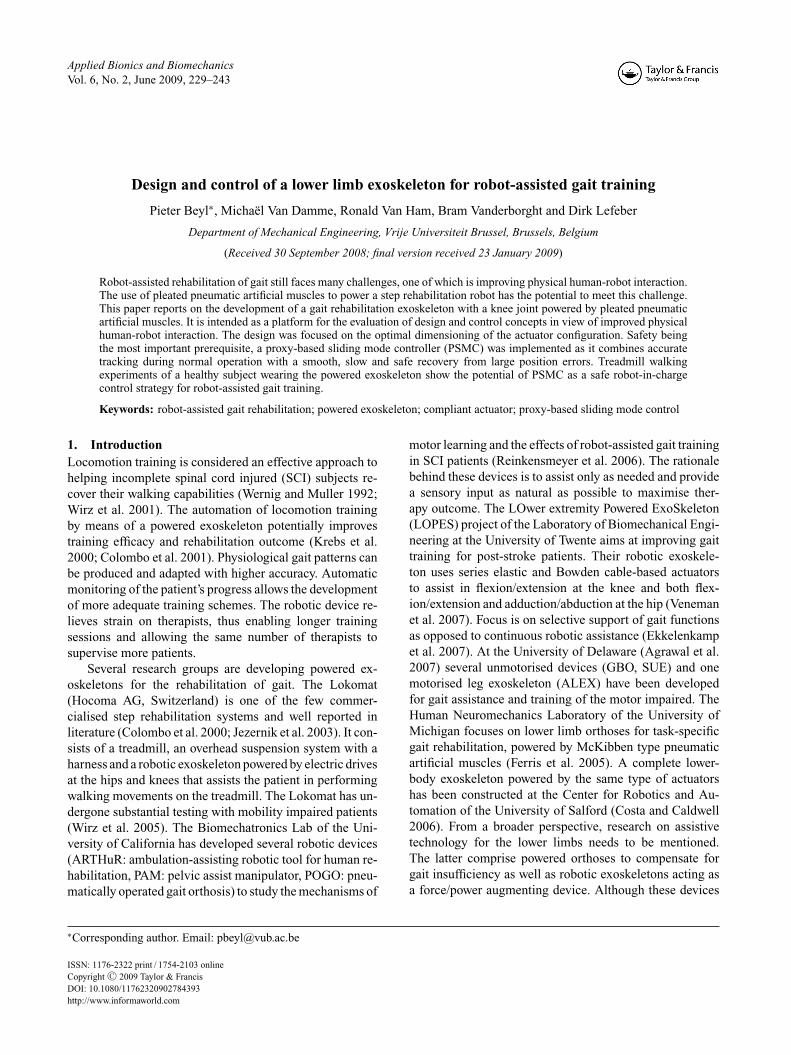
The exoskeleton (see Figure 1) is unilateral and consists ofan adjustable upper body link, upper leg link and lower leg
Figure 1. Close up of the unilateral exoskeleton with the kneejoint powered by pleated pneumatic artificial muscles.
Applied Bionics and Biomechanics 231
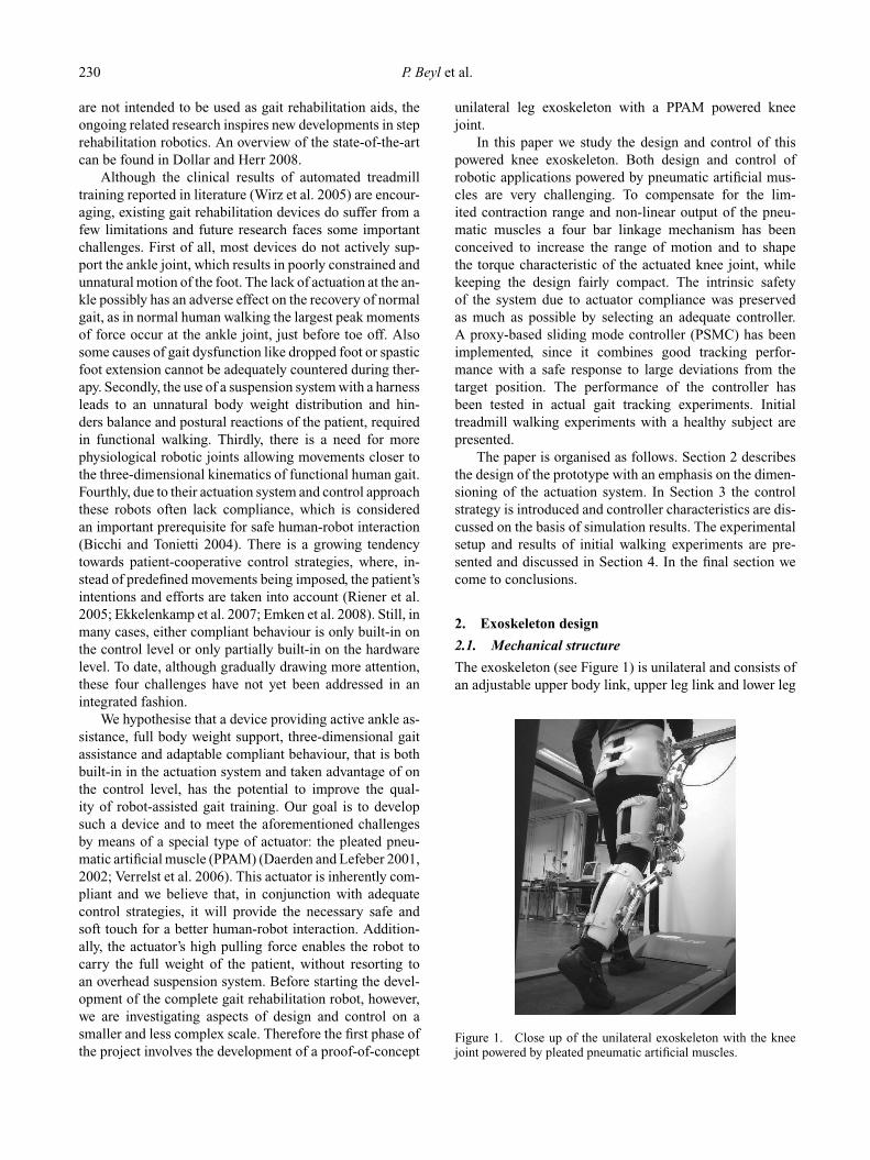
link interconnected by hinge joints. Only the knee joint ispowered by pleated pneumatic artificial muscles (PPAMs).The actuation system has been designed to provide the ex-oskeleton with enough power to fully support normal hu-man gait in the absence of human knee joint power. The de-sign procedure is explained in detail in Subsection 2.2. Theactuators are tethered to an external pressurised air supplysystem with a high performance pressure regulating valve(Kolvenbach KPS 3/4-00) for each PPAM. As mentionedin the introductory section, the exoskeleton is intended as aproof-of-concept device for the development and testing ofdesign and control concepts. For this reason, the design hasbeen tailored to the requirements of an average male subject.For the adjustability of the device only small inter-subjectvariations have been taken into account. Two-piece rigidthermoplastic shells with a foam inlay and Velcro strapsprovide an adaptable fit at the lower and upper leg andthe hip. Their position and orientation with respect to theexoskeleton frame are adjustable by means of slider mech-anisms. Mechanical limiters prevent hyperextension andhyperflexion of the knee. A supportive arm (see Figure 2)with zero free length spring mechanism (Rahman et al.1995) passively gravity-balances the exoskeleton to reduceasymmetrical loading of the subject wearing the device.The telescopic arm is connected to the upper body link bymeans of a ball joint. Additionally, the arm can pivot about ahorizontal and vertical axis near the supporting wall. In thisway all 6 degrees of freedom (DOF) of the upper body linkare unconstrained, allowing unhindered treadmill walking.The weight of the exoskeleton, including the attachments,is 5.8 kg.
Figure 2. Unilateral exoskeleton with supportive arm.
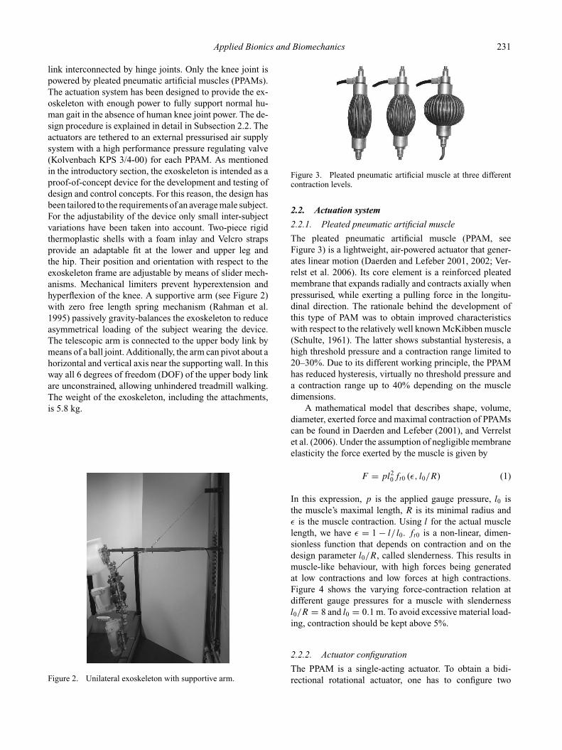
Figure 3. Pleated pneumatic artificial muscle at three differentcontraction levels.
2.2. Actuation system
2.2.1. Pleated pneumatic artificial muscle
The pleated pneumatic artificial muscle (PPAM, seeFigure 3) is a lightweight, air-powered actuator that gener-ates linear motion (Daerden and Lefeber 2001, 2002; Ver-relst et al. 2006). Its core element is a reinforced pleatedmembrane that expands radially and contracts axially whenpressurised, while exerting a pulling force in the longitu-dinal direction. The rationale behind the development ofthis type of PAM was to obtain improved characteristicswith respect to the relatively well known McKibben muscle(Schulte, 1961). The latter shows substantial hysteresis, ahigh threshold pressure and a contraction range limited to20–30%. Due to its different working principle, the PPAMhas reduced hysteresis, virtually no threshold pressure anda contraction range up to 40% depending on the muscledimensions.
A mathematical model that describes shape, volume,diameter, exerted force and maximal contraction of PPAMscan be found in Daerden and Lefeber (2001), and Verrelstet al. (2006). Under the assumption of negligible membraneelasticity the force exerted by the muscle is given by
F = pl20ft0 (ε, l0/R) (1)
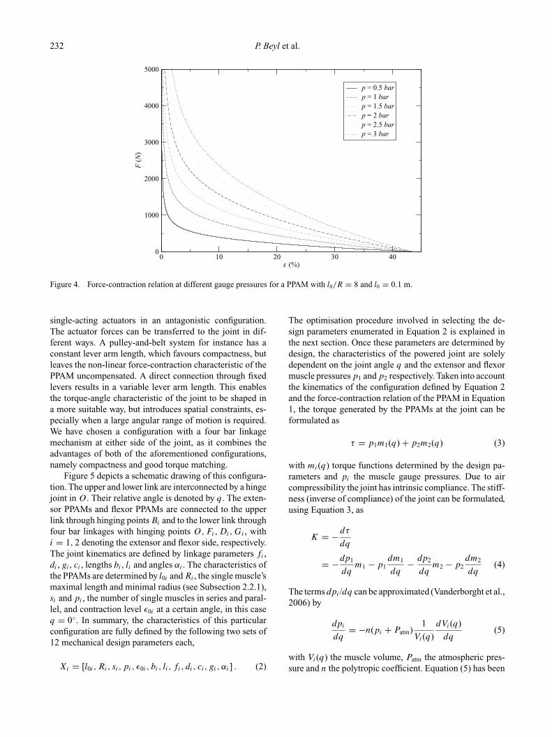
In this expression, p is the applied gauge pressure, l0 isthe muscle’s maximal length, R is its minimal radius andε is the muscle contraction. Using l for the actual musclelength, we have ε = 1 − l/ l0. ft0 is a non-linear, dimen-sionless function that depends on contraction and on thedesign parameter l0/R, called slenderness. This results inmuscle-like behaviour, with high forces being generatedat low contractions and low forces at high contractions.Figure 4 shows the varying force-contraction relation atdifferent gauge pressures for a muscle with slendernessl0/R = 8 and l0 = 0.1 m. To avoid excessive material load-ing, contraction should be kept above 5%.
2.2.2. Actuator configuration
The PPAM is a single-acting actuator. To obtain a bidi-rectional rotational actuator, one has to configure two
232 P. Beyl et al.
0 10 20 30 40ε (%)
0
1000
2000
3000
4000
5000
F (
N)
p = 0.5 barp = 1 barp = 1.5 barp = 2 barp = 2.5 barp = 3 bar
Figure 4. Force-contraction relation at different gauge pressures for a PPAM with l0/R = 8 and l0 = 0.1 m.
single-acting actuators in an antagonistic configuration.The actuator forces can be transferred to the joint in dif-ferent ways. A pulley-and-belt system for instance has aconstant lever arm length, which favours compactness, butleaves the non-linear force-contraction characteristic of thePPAM uncompensated. A direct connection through fixedlevers results in a variable lever arm length. This enablesthe torque-angle characteristic of the joint to be shaped ina more suitable way, but introduces spatial constraints, es-pecially when a large angular range of motion is required.We have chosen a configuration with a four bar linkagemechanism at either side of the joint, as it combines theadvantages of both of the aforementioned configurations,namely compactness and good torque matching.
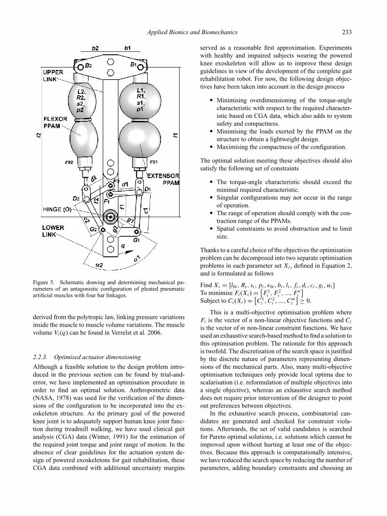
Figure 5 depicts a schematic drawing of this configura-tion. The upper and lower link are interconnected by a hingejoint in O. Their relative angle is denoted by q. The exten-sor PPAMs and flexor PPAMs are connected to the upperlink through hinging points Bi and to the lower link throughfour bar linkages with hinging points O,Fi,Di,Gi , withi = 1, 2 denoting the extensor and flexor side, respectively.The joint kinematics are defined by linkage parameters fi ,di , gi , ci , lengths bi , li and angles αi . The characteristics ofthe PPAMs are determined by l0i and Ri , the single muscle’smaximal length and minimal radius (see Subsection 2.2.1),si and pi , the number of single muscles in series and paral-lel, and contraction level ε0i at a certain angle, in this caseq = 0◦. In summary, the characteristics of this particularconfiguration are fully defined by the following two sets of12 mechanical design parameters each,
Xi = [l0i , Ri, si, pi, ε0i , bi, li , fi, di, ci, gi, αi] . (2)
The optimisation procedure involved in selecting the de-sign parameters enumerated in Equation 2 is explained inthe next section. Once these parameters are determined bydesign, the characteristics of the powered joint are solelydependent on the joint angle q and the extensor and flexormuscle pressures p1 and p2 respectively. Taken into accountthe kinematics of the configuration defined by Equation 2and the force-contraction relation of the PPAM in Equation1, the torque generated by the PPAMs at the joint can beformulated as
τ = p1m1(q) + p2m2(q) (3)
with mi(q) torque functions determined by the design pa-rameters and pi the muscle gauge pressures. Due to aircompressibility the joint has intrinsic compliance. The stiff-ness (inverse of compliance) of the joint can be formulated,using Equation 3, as
K = −dτ
dq
= −dp1
dqm1 − p1
dm1
dq− dp2
dqm2 − p2
dm2
dq(4)
The terms dpi /dq can be approximated (Vanderborght et al.,2006) by
dpi
dq= −n(pi + Patm)
1
Vi(q)
dVi(q)
dq(5)
with Vi(q) the muscle volume, Patm the atmospheric pres-sure and n the polytropic coefficient. Equation (5) has been
Applied Bionics and Biomechanics 233
Figure 5. Schematic drawing and determining mechanical pa-rameters of an antagonistic configuration of pleated pneumaticartificial muscles with four bar linkages.
derived from the polytropic law, linking pressure variationsinside the muscle to muscle volume variations. The musclevolume Vi(q) can be found in Verrelst et al. 2006.
2.2.3. Optimised actuator dimensioning
Although a feasible solution to the design problem intro-duced in the previous section can be found by trial-and-error, we have implemented an optimisation procedure inorder to find an optimal solution. Anthropometric data(NASA, 1978) was used for the verification of the dimen-sions of the configuration to be incorporated into the ex-oskeleton structure. As the primary goal of the poweredknee joint is to adequately support human knee joint func-tion during treadmill walking, we have used clinical gaitanalysis (CGA) data (Winter, 1991) for the estimation ofthe required joint torque and joint range of motion. In theabsence of clear guidelines for the actuation system de-sign of powered exoskeletons for gait rehabilitation, theseCGA data combined with additional uncertainty margins
served as a reasonable first approximation. Experimentswith healthy and impaired subjects wearing the poweredknee exoskeleton will allow us to improve these designguidelines in view of the development of the complete gaitrehabilitation robot. For now, the following design objec-tives have been taken into account in the design process
� Minimising overdimensioning of the torque-anglecharacteristic with respect to the required character-istic based on CGA data, which also adds to systemsafety and compactness.
� Minimising the loads exerted by the PPAM on thestructure to obtain a lightweight design.
� Maximising the compactness of the configuration.
The optimal solution meeting these objectives should alsosatisfy the following set of constraints
� The torque-angle characteristic should exceed theminimal required characteristic.
� Singular configurations may not occur in the rangeof operation.
� The range of operation should comply with the con-traction range of the PPAMs.
� Spatial constraints to avoid obstruction and to limitsize.
Thanks to a careful choice of the objectives the optimisationproblem can be decomposed into two separate optimisationproblems in each parameter set Xi , defined in Equation 2,and is formulated as follows
Find Xi = [l0i , Ri, si, pi, ε0i , bi, li , fi, di, ci, gi, αi]To minimise Fi(Xi) = [
F 1i , F 2
i , ..., F ni
]
Subject to Ci(Xi) = [C1
i , C2i , ..., C
mi
] ≥ 0.
This is a multi-objective optimisation problem whereFi is the vector of n non-linear objective functions and Ci
is the vector of m non-linear constraint functions. We haveused an exhaustive search-based method to find a solution tothis optimisation problem. The rationale for this approachis twofold. The discretisation of the search space is justifiedby the discrete nature of parameters representing dimen-sions of the mechanical parts. Also, many multi-objectiveoptimisation techniques only provide local optima due toscalarisation (i.e. reformulation of multiple objectives intoa single objective), whereas an exhaustive search methoddoes not require prior intervention of the designer to pointout preferences between objectives.
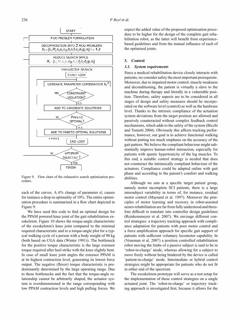
In the exhaustive search process, combinatorial can-didates are generated and checked for constraint viola-tions. Afterwards, the set of valid candidates is searchedfor Pareto optimal solutions, i.e. solutions which cannot beimproved upon without hurting at least one of the objec-tives. Because this approach is computationally intensive,we have reduced the search space by reducing the number ofparameters, adding boundary constraints and choosing an
234 P. Beyl et al.
26 28 30 32 34 36 38
4200
4300
4400
4500
4600
4700
4800
F 1 (Nm)
F3
(N)
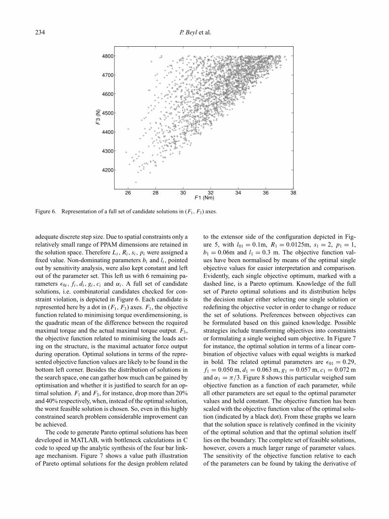
Figure 6. Representation of a full set of candidate solutions in (F1, F3) axes.
adequate discrete step size. Due to spatial constraints only arelatively small range of PPAM dimensions are retained inthe solution space. Therefore Li, Ri, si, pi were assigned afixed value. Non-dominating parameters bi and li , pointedout by sensitivity analysis, were also kept constant and leftout of the parameter set. This left us with 6 remaining pa-rameters ε0i , fi, di, gi, ci and αi . A full set of candidatesolutions, i.e. combinatorial candidates checked for con-straint violation, is depicted in Figure 6. Each candidate isrepresented here by a dot in (F1, F3) axes. F1, the objectivefunction related to minimising torque overdimensioning, isthe quadratic mean of the difference between the requiredmaximal torque and the actual maximal torque output. F3,the objective function related to minimising the loads act-ing on the structure, is the maximal actuator force outputduring operation. Optimal solutions in terms of the repre-sented objective function values are likely to be found in thebottom left corner. Besides the distribution of solutions inthe search space, one can gather how much can be gained byoptimisation and whether it is justified to search for an op-timal solution. F1 and F3, for instance, drop more than 20%and 40% respectively, when, instead of the optimal solution,the worst feasible solution is chosen. So, even in this highlyconstrained search problem considerable improvement canbe achieved.
The code to generate Pareto optimal solutions has beendeveloped in MATLAB, with bottleneck calculations in Ccode to speed up the analytic synthesis of the four bar link-age mechanism. Figure 7 shows a value path illustrationof Pareto optimal solutions for the design problem related
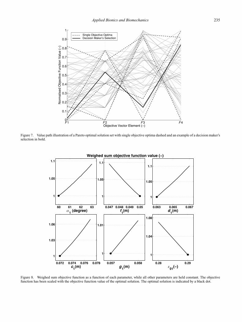
to the extensor side of the configuration depicted in Fig-ure 5, with l01 = 0.1m, R1 = 0.0125m, s1 = 2, p1 = 1,b1 = 0.06m and l1 = 0.3 m. The objective function val-ues have been normalised by means of the optimal singleobjective values for easier interpretation and comparison.Evidently, each single objective optimum, marked with adashed line, is a Pareto optimum. Knowledge of the fullset of Pareto optimal solutions and its distribution helpsthe decision maker either selecting one single solution orredefining the objective vector in order to change or reducethe set of solutions. Preferences between objectives canbe formulated based on this gained knowledge. Possiblestrategies include transforming objectives into constraintsor formulating a single weighed sum objective. In Figure 7for instance, the optimal solution in terms of a linear com-bination of objective values with equal weights is markedin bold. The related optimal parameters are ε01 = 0.29,f1 = 0.050 m, d1 = 0.063 m, g1 = 0.057 m, c1 = 0.072 mand α1 = π/3. Figure 8 shows this particular weighed sumobjective function as a function of each parameter, whileall other parameters are set equal to the optimal parametervalues and held constant. The objective function has beenscaled with the objective function value of the optimal solu-tion (indicated by a black dot). From these graphs we learnthat the solution space is relatively confined in the vicinityof the optimal solution and that the optimal solution itselflies on the boundary. The complete set of feasible solutions,however, covers a much larger range of parameter values.The sensitivity of the objective function relative to eachof the parameters can be found by taking the derivative of
Applied Bionics and Biomechanics 235
F1 F 2 F3 F40
0.1
0.2
0.3
0.4
0.5
0.6
0.7
0.8
0.9
1Single Objective OptimaDecision Maker’s Selection
Figure 7. Value path illustration of a Pareto optimal solution set with single objective optima dashed and an example of a decision maker’sselection in bold.
60 61 62 63
1
1.05
α1 (degree)
0.047 0.048 0.049 0.05
1
1.05
1.11.1
f1(m)
0.063 0.065 0.067
1
1.05
1.1
d1(m)
0.072 0.074 0.076 0.078
1
1.03
1.06
c1(m)
0.057 0.058
1
1.01
g1(m)
0.28 0.29
1
1.04
1.08
ε01
Figure 8. Weighed sum objective function as a function of each parameter, while all other parameters are held constant. The objectivefunction has been scaled with the objective function value of the optimal solution. The optimal solution is indicated by a black dot.
236 P. Beyl et al.
Figure 9. Flow chart of the exhaustive search optimisation pro-cedure.
each of the curves. A 6% change of parameter d1 causesfor instance a drop in optimality of 10%. The entire optimi-sation procedure is summarised in a flow chart depicted inFigure 9.
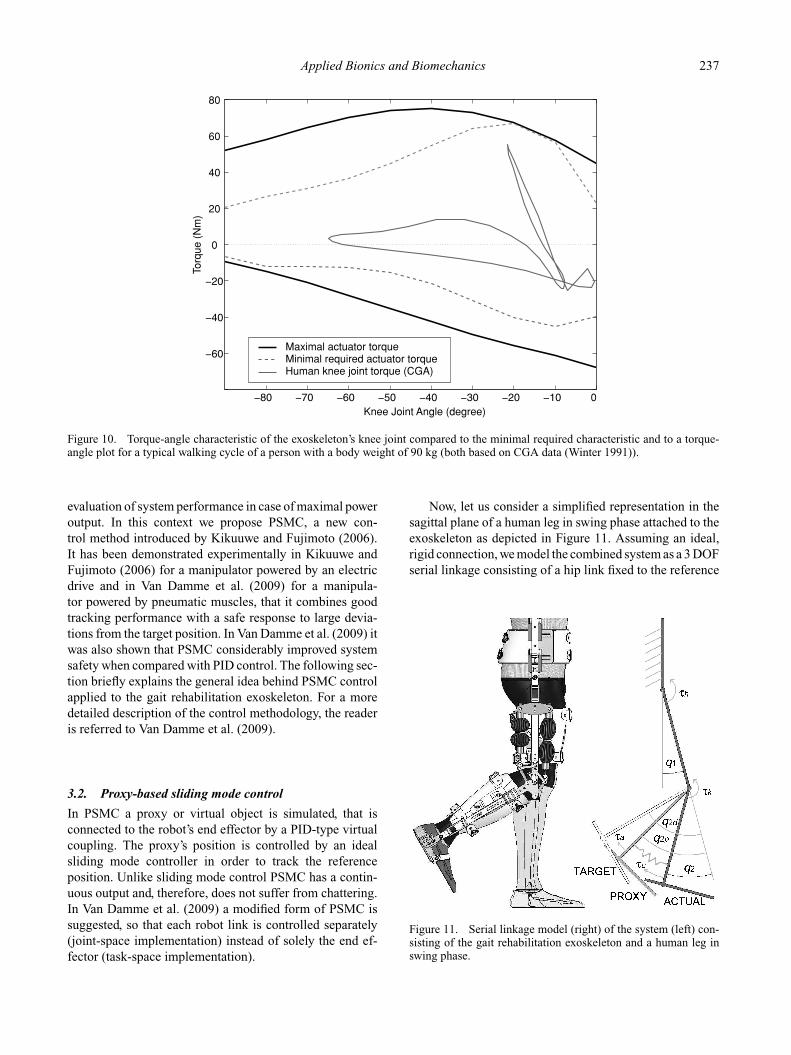
We have used this code to find an optimal design forthe PPAM powered knee joint of the gait rehabilitation ex-oskeleton. Figure 10 shows the torque-angle characteristicof the exoskeleton’s knee joint compared to the minimalrequired characteristic and to a torque-angle plot for a typ-ical walking cycle of a person with a body weight of 90 kg(both based on CGA data (Winter 1991)). The bottleneckfor the positive torque characteristic is the large extensortorque required after heel strike with the knee slightly bent.In case of small knee joint angles the extensor PPAM isat its highest contraction level, generating its lowest forceoutput. The negative (flexor) torque characteristic is pre-dominantly determined by the large operating range. Dueto these bottlenecks and the fact that the torque-angle re-lationship cannot be arbitrarily shaped, the actuator sys-tem is overdimensioned in the range corresponding withlow PPAM contraction levels and high pulling forces. We
expect the added value of the proposed optimisation proce-dure to be higher for the design of the complete gait reha-bilitation robot, as the latter will benefit from experience-based guidelines and from the mutual influence of each ofthe optimised joints.
3. Control
3.1. System requirements
Since a medical rehabilitation device closely interacts withpatients, we consider safety the most important prerequisite.Moreover, due to impaired motor control, muscle weaknessand deconditioning, the patient is virtually a slave to themachine during therapy and literally in a vulnerable posi-tion. Therefore, safety aspects are to be considered in allstages of design and safety measures should be incorpo-rated on the software level (control) as well as the hardwarelevel. Thanks to the intrinsic compliance of the actuationsystem deviations from the target position are allowed andpassively counteracted without complex feedback controlmechanisms, which adds to the safety of the system (Bicchiand Tonietti 2004). Obviously this affects tracking perfor-mance, however, our goal is to achieve functional walkingwithout putting too much emphasis on the accuracy of thegait pattern. We believe the compliant behaviour might sub-stantially improve human-robot interaction, especially forpatients with spastic hypertonicity of the leg muscles. Tothis end, a suitable control strategy is needed that doesnot counteract the intrinsically compliant behaviour of theactuators. Compliance could be adapted online with gaitphase and according to the patient’s comfort and walkingabilities.
Although we aim at a specific target patient group,namely motor incomplete SCI patients, there is a largeintersubject variability in terms of, for instance, residualmotor control (Maynard et al. 1997). Moreover the prin-ciples of motor learning and recovery in robot-assistedneuro-rehabilitation are far from fully understood and there-fore difficult to translate into controller design guidelines(Reinkensmeyer et al. 2007). We envisage different con-trol strategies: a trajectory tracking approach with compli-ance adaptation for patients with poor motor control anda force amplification approach for specific gait support ofpatients with sufficient voluntary locomotor capability. In(Veneman et al. 2007) a position controlled rehabilitationrobot moving the limbs of a passive subject is said to be in‘robot-in-charge’ mode, whereas allowing for a subject tomove freely without being hindered by the device is called‘patient-in-charge’ mode. Intermediate or hybrid controlstrategies might be appropriate for patients who do not fitin either end of the spectrum.
The exoskeleton prototype will serve as a test setup forthe implementation of these control strategies on a singleactuated joint. The ‘robot-in-charge’ or trajectory track-ing approach is investigated first, because it allows for the
Applied Bionics and Biomechanics 237
0
0
20
40
60
80
Knee Joint Angle (degree)
Torq
ue (
Nm
)
Maximal actuator torqueMinimal required actuator torqueHuman knee joint torque (CGA)
Figure 10. Torque-angle characteristic of the exoskeleton’s knee joint compared to the minimal required characteristic and to a torque-angle plot for a typical walking cycle of a person with a body weight of 90 kg (both based on CGA data (Winter 1991)).
evaluation of system performance in case of maximal poweroutput. In this context we propose PSMC, a new con-trol method introduced by Kikuuwe and Fujimoto (2006).It has been demonstrated experimentally in Kikuuwe andFujimoto (2006) for a manipulator powered by an electricdrive and in Van Damme et al. (2009) for a manipula-tor powered by pneumatic muscles, that it combines goodtracking performance with a safe response to large devia-tions from the target position. In Van Damme et al. (2009) itwas also shown that PSMC considerably improved systemsafety when compared with PID control. The following sec-tion briefly explains the general idea behind PSMC controlapplied to the gait rehabilitation exoskeleton. For a moredetailed description of the control methodology, the readeris referred to Van Damme et al. (2009).
3.2. Proxy-based sliding mode control
In PSMC a proxy or virtual object is simulated, that isconnected to the robot’s end effector by a PID-type virtualcoupling. The proxy’s position is controlled by an idealsliding mode controller in order to track the referenceposition. Unlike sliding mode control PSMC has a contin-uous output and, therefore, does not suffer from chattering.In Van Damme et al. (2009) a modified form of PSMC issuggested, so that each robot link is controlled separately(joint-space implementation) instead of solely the end ef-fector (task-space implementation).
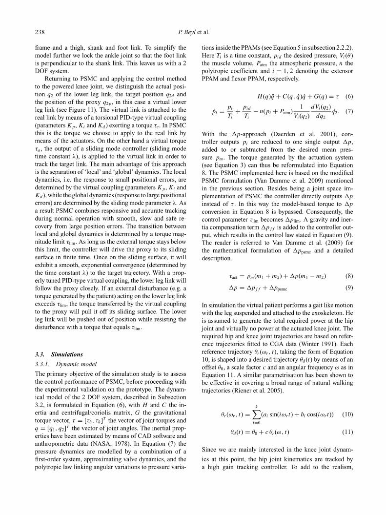
Now, let us consider a simplified representation in thesagittal plane of a human leg in swing phase attached to theexoskeleton as depicted in Figure 11. Assuming an ideal,rigid connection, we model the combined system as a 3 DOFserial linkage consisting of a hip link fixed to the reference
Figure 11. Serial linkage model (right) of the system (left) con-sisting of the gait rehabilitation exoskeleton and a human leg inswing phase.
238 P. Beyl et al.
frame and a thigh, shank and foot link. To simplify themodel further we lock the ankle joint so that the foot linkis perpendicular to the shank link. This leaves us with a 2DOF system.
Returning to PSMC and applying the control methodto the powered knee joint, we distinguish the actual posi-tion q2 of the lower leg link, the target position q2d andthe position of the proxy q2p, in this case a virtual lowerleg link (see Figure 11). The virtual link is attached to thereal link by means of a torsional PID-type virtual coupling(parameters Kp, Ki and Kd ) exerting a torque τc. In PSMCthis is the torque we choose to apply to the real link bymeans of the actuators. On the other hand a virtual torqueτa , the output of a sliding mode controller (sliding modetime constant λ), is applied to the virtual link in order totrack the target link. The main advantage of this approachis the separation of ‘local’ and ‘global’ dynamics. The localdynamics, i.e. the response to small positional errors, aredetermined by the virtual coupling (parameters Kp, Ki andKd ), while the global dynamics (response to large positionalerrors) are determined by the sliding mode parameter λ. Asa result PSMC combines responsive and accurate trackingduring normal operation with smooth, slow and safe re-covery from large position errors. The transition betweenlocal and global dynamics is determined by a torque mag-nitude limit τlim. As long as the external torque stays belowthis limit, the controller will drive the proxy to its slidingsurface in finite time. Once on the sliding surface, it willexhibit a smooth, exponential convergence (determined bythe time constant λ) to the target trajectory. With a prop-erly tuned PID-type virtual coupling, the lower leg link willfollow the proxy closely. If an external disturbance (e.g. atorque generated by the patient) acting on the lower leg linkexceeds τlim, the torque transferred by the virtual couplingto the proxy will pull it off its sliding surface. The lowerleg link will be pushed out of position while resisting thedisturbance with a torque that equals τlim.
3.3. Simulations
3.3.1. Dynamic model
The primary objective of the simulation study is to assessthe control performance of PSMC, before proceeding withthe experimental validation on the prototype. The dynam-ical model of the 2 DOF system, described in Subsection3.2, is formulated in Equation (6), with H and C the in-ertia and centrifugal/coriolis matrix, G the gravitationaltorque vector, τ = [τh, τk]T the vector of joint torques andq = [q1, q2]T the vector of joint angles. The inertial prop-erties have been estimated by means of CAD software andanthropometric data (NASA, 1978). In Equation (7) thepressure dynamics are modelled by a combination of afirst-order system, approximating valve dynamics, and thepolytropic law linking angular variations to pressure varia-
tions inside the PPAMs (see Equation 5 in subsection 2.2.2).Here Ti is a time constant, pid the desired pressure, Vi(θ )the muscle volume, Patm the atmospheric pressure, n thepolytropic coefficient and i = 1, 2 denoting the extensorPPAM and flexor PPAM, respectively.
H (q)q + C(q, q)q + G(q) = τ (6)
pi = pi
Ti
+ pid
Ti
− n(pi + Patm)1
Vi(q2)
dVi(q2)
dq2q2. (7)
With the �p-approach (Daerden et al. 2001), con-troller outputs pi are reduced to one single output �p,added to or subtracted from the desired mean pres-sure pm. The torque generated by the actuation system(see Equation 3) can thus be reformulated into Equation8. The PSMC implemented here is based on the modifiedPSMC formulation (Van Damme et al. 2009) mentionedin the previous section. Besides being a joint space im-plementation of PSMC the controller directly outputs �p
instead of τ . In this way the model-based torque to �p
conversion in Equation 8 is bypassed. Consequently, thecontrol parameter τlim becomes �plim. A gravity and iner-tia compensation term �pff is added to the controller out-put, which results in the control law stated in Equation (9).The reader is referred to Van Damme et al. (2009) forthe mathematical formulation of �ppsmc and a detaileddescription.
τact = pm(m1 + m2) + �p(m1 − m2) (8)
�p = �pff + �ppsmc (9)
In simulation the virtual patient performs a gait like motionwith the leg suspended and attached to the exoskeleton. Heis assumed to generate the total required power at the hipjoint and virtually no power at the actuated knee joint. Therequired hip and knee joint trajectories are based on refer-ence trajectories fitted to CGA data (Winter 1991). Eachreference trajectory θr (ωr, t), taking the form of Equation10, is shaped into a desired trajectory θd (t) by means of anoffset θ0, a scale factor c and an angular frequency ω as inEquation 11. A similar parametrisation has been shown tobe effective in covering a broad range of natural walkingtrajectories (Riener et al. 2005).
θr (ωr, t) =k∑
i=0
(ai sin(iωr t) + bi cos(iωr t)) (10)
θd (t) = θ0 + c θr (ω, t) (11)
Since we are mainly interested in the knee joint dynam-
ics at this point, the hip joint kinematics are tracked bya high gain tracking controller. To add to the realism,
Applied Bionics and Biomechanics 239
0
q 2 (de
gree
)
0 1 2 3 4 5 6 7 8
12
0
Time (s)Pat
ient
Tor
que
(Nm
) q2d
q2 (∆p
lim= 0.5) q
2 (∆p
lim= 0.65)
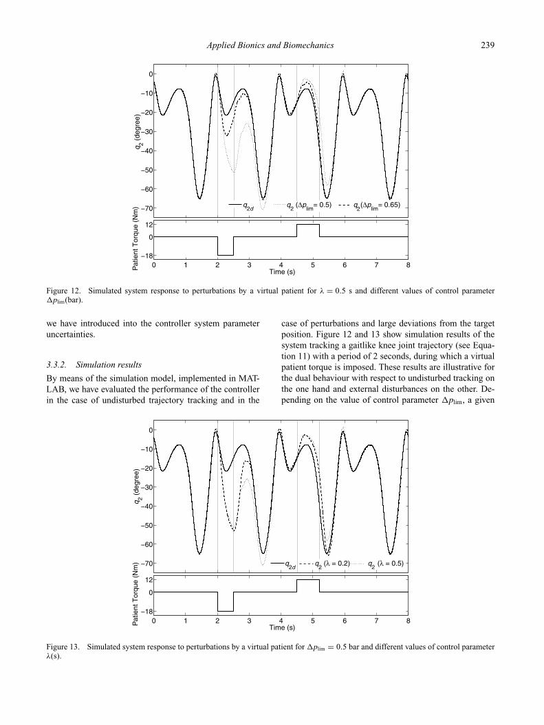
Figure 12. Simulated system response to perturbations by a virtual patient for λ = 0.5 s and different values of control parameter�plim(bar).
we have introduced into the controller system parameteruncertainties.
3.3.2. Simulation results
By means of the simulation model, implemented in MAT-LAB, we have evaluated the performance of the controllerin the case of undisturbed trajectory tracking and in the
case of perturbations and large deviations from the targetposition. Figure 12 and 13 show simulation results of thesystem tracking a gaitlike knee joint trajectory (see Equa-tion 11) with a period of 2 seconds, during which a virtualpatient torque is imposed. These results are illustrative forthe dual behaviour with respect to undisturbed tracking onthe one hand and external disturbances on the other. De-pending on the value of control parameter �plim, a given
0
q 2 (de
gree
)
0 1 2 3 4 5 6 7 8
0
12
Time (s)Pat
ient
Tor
que
(Nm
) q2d
q2 (λ = 0.2) q
2 (λ = 0.5)
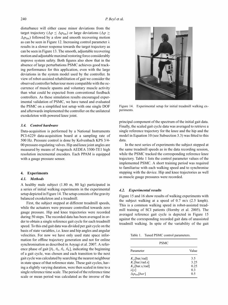
Figure 13. Simulated system response to perturbations by a virtual patient for �plim = 0.5 bar and different values of control parameterλ(s).
240 P. Beyl et al.
disturbance will either cause minor deviations from thetarget trajectory (�p ≤ �plim) or large deviations (�p ≥�plim) followed by a slow and smooth recovering motionas can be seen in Figure 12. Increasing control parameter λ
results in a slower response towards the target trajectory ascan be seen in Figure 13. The smooth, adjustable recoveringmotion and adjustable maximal restoring force considerablyimprove system safety. Both figures also show that in theabsence of large perturbations PSMC achieves good track-ing performance for this application, even with the largedeviations in the system model used by the controller. Inview of robot-assisted rehabilitation of gait we consider theobserved controller behaviour more compatible with the oc-currence of muscle spasms and voluntary muscle activitythan what could be expected from conventional feedbackcontrollers. As these simulation results encouraged exper-imental validation of PSMC, we have tuned and evaluatedthe PSMC on a simplified test setup with one single DOFand afterwards implemented the controller on the unilateralexoskeleton with powered knee joint.
3.4. Control hardware
Data-acquisition is performed by a National InstrumentsPCI-6229 data-acquisition board at a sampling rate of500 Hz. Pressure control is done by Kolvenbach KPS 3/4-00 pressure-regulating valves. Hip and knee joint angles aremeasured by means of Avagotech AEDEA 3300-TE1 highresolution incremental encoders. Each PPAM is equippedwith a gauge pressure sensor.
4. Experiments
4.1. Methods
A healthy male subject (1.80 m, 80 kg) participated ina series of initial walking experiments in the experimentalsetup depicted in Figure 14. The setup consists of the gravitybalanced exoskeleton and a treadmill.
First, the subject stepped at different treadmill speeds,while the actuators were pressure controlled towards zerogauge pressure. Hip and knee trajectories were recordedduring 50 steps. The recorded data has been averaged in or-der to obtain a single reference gait cycle for each treadmillspeed. To this end gait data was divided per gait cycle on thebasis of state variables, i.e. knee and hip angles and angularvelocities. For now we have only used state space infor-mation for offline trajectory generation and not for onlinesynchronisation as described in Aoyagi et al. 2007. A refer-ence phase of gait [θk, θh, θk, θh], indicating the beginningof a gait cycle, was chosen and each transition to the nextgait cycle was calculated by searching the nearest neighbourin state space of that reference state. These gait cycles, hav-ing a slightly varying duration, were then scaled in time to asingle reference time scale. The period of the reference timescale or mean period was calculated as the inverse of the
Figure 14. Experimental setup for initial treadmill walking ex-periments.
principal component of the spectrum of the initial gait data.Finally, the scaled gait cycle data was averaged to retrieve asingle reference trajectory for the knee and the hip and themodel in Equation 10 (see Subsection 3.3) was fitted to thisdata.
In the next series of experiments the subject stepped atthe same treadmill speeds as in the data recording session,while the PSMC tracked the corresponding reference kneetrajectory. Table 1 lists the control parameter values of theimplemented PSMC. A short training period was requiredto familiarise with each walking speed and to synchronisestepping with the device. Hip and knee trajectories as wellas muscle gauge pressures were recorded.
4.2. Experimental results
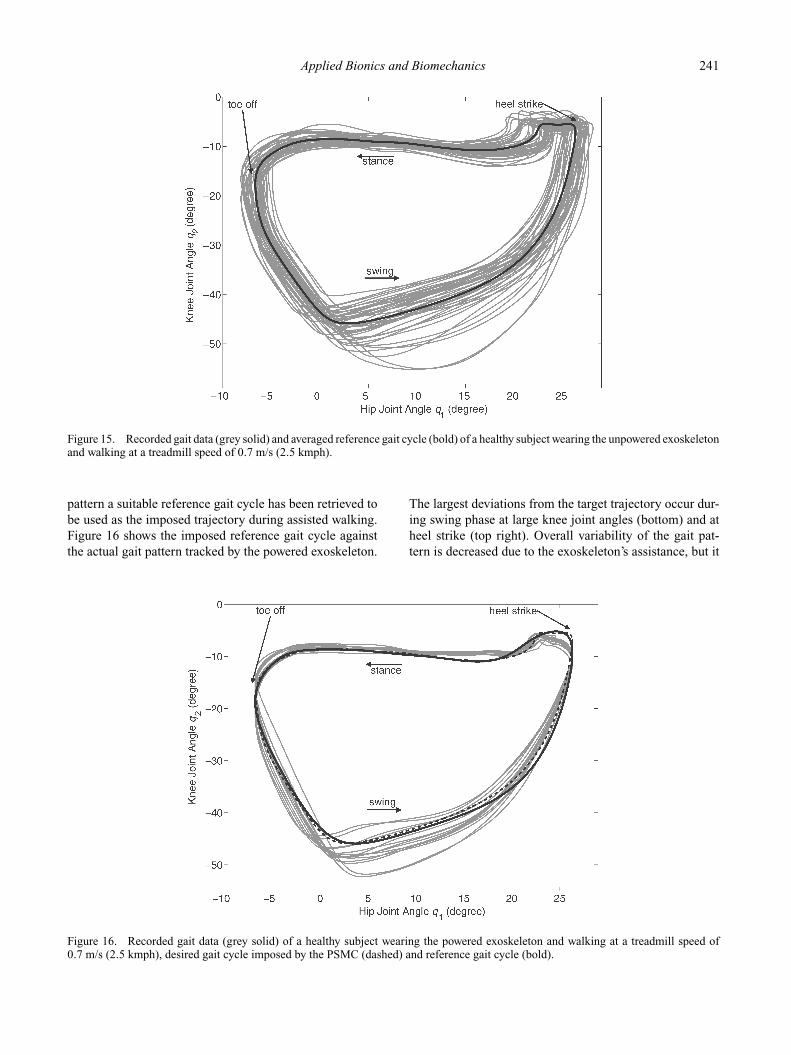
Figure 15 and 16 show results of walking experiments withthe subject walking at a speed of 0.7 m/s (2.5 kmph).This is a common walking speed in robot-assisted tread-mill training of SCI patients (Hornby et al. 2005). Theaveraged reference gait cycle is depicted in Figure 15against the corresponding recorded gait data of unassistedtreadmill walking. In spite of the variability of the gait
Table 1. Tuned PSMC control parameters.
PSMC
Parameter Value
Kp[bar/rad] 3.5Ki[bar/rad.s] 3.25Kd [bar.s/rad] 0.25λ[s] 0.3�plim[bar] 0.5
Applied Bionics and Biomechanics 241
Figure 15. Recorded gait data (grey solid) and averaged reference gait cycle (bold) of a healthy subject wearing the unpowered exoskeletonand walking at a treadmill speed of 0.7 m/s (2.5 kmph).
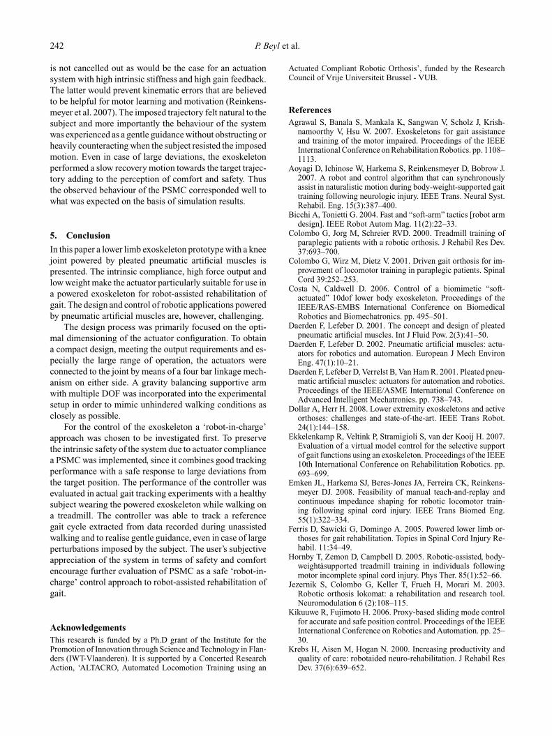
pattern a suitable reference gait cycle has been retrieved tobe used as the imposed trajectory during assisted walking.Figure 16 shows the imposed reference gait cycle againstthe actual gait pattern tracked by the powered exoskeleton.
The largest deviations from the target trajectory occur dur-ing swing phase at large knee joint angles (bottom) and atheel strike (top right). Overall variability of the gait pat-tern is decreased due to the exoskeleton’s assistance, but it
Figure 16. Recorded gait data (grey solid) of a healthy subject wearing the powered exoskeleton and walking at a treadmill speed of0.7 m/s (2.5 kmph), desired gait cycle imposed by the PSMC (dashed) and reference gait cycle (bold).
242 P. Beyl et al.
is not cancelled out as would be the case for an actuationsystem with high intrinsic stiffness and high gain feedback.The latter would prevent kinematic errors that are believedto be helpful for motor learning and motivation (Reinkens-meyer et al. 2007). The imposed trajectory felt natural to thesubject and more importantly the behaviour of the systemwas experienced as a gentle guidance without obstructing orheavily counteracting when the subject resisted the imposedmotion. Even in case of large deviations, the exoskeletonperformed a slow recovery motion towards the target trajec-tory adding to the perception of comfort and safety. Thusthe observed behaviour of the PSMC corresponded well towhat was expected on the basis of simulation results.
5. Conclusion
In this paper a lower limb exoskeleton prototype with a kneejoint powered by pleated pneumatic artificial muscles ispresented. The intrinsic compliance, high force output andlow weight make the actuator particularly suitable for use ina powered exoskeleton for robot-assisted rehabilitation ofgait. The design and control of robotic applications poweredby pneumatic artificial muscles are, however, challenging.
The design process was primarily focused on the opti-mal dimensioning of the actuator configuration. To obtaina compact design, meeting the output requirements and es-pecially the large range of operation, the actuators wereconnected to the joint by means of a four bar linkage mech-anism on either side. A gravity balancing supportive armwith multiple DOF was incorporated into the experimentalsetup in order to mimic unhindered walking conditions asclosely as possible.
For the control of the exoskeleton a ‘robot-in-charge’approach was chosen to be investigated first. To preservethe intrinsic safety of the system due to actuator compliancea PSMC was implemented, since it combines good trackingperformance with a safe response to large deviations fromthe target position. The performance of the controller wasevaluated in actual gait tracking experiments with a healthysubject wearing the powered exoskeleton while walking ona treadmill. The controller was able to track a referencegait cycle extracted from data recorded during unassistedwalking and to realise gentle guidance, even in case of largeperturbations imposed by the subject. The user’s subjectiveappreciation of the system in terms of safety and comfortencourage further evaluation of PSMC as a safe ‘robot-in-charge’ control approach to robot-assisted rehabilitation ofgait.
AcknowledgementsThis research is funded by a Ph.D grant of the Institute for thePromotion of Innovation through Science and Technology in Flan-ders (IWT-Vlaanderen). It is supported by a Concerted ResearchAction, ‘ALTACRO, Automated Locomotion Training using an
Actuated Compliant Robotic Orthosis’, funded by the ResearchCouncil of Vrije Universiteit Brussel - VUB.
ReferencesAgrawal S, Banala S, Mankala K, Sangwan V, Scholz J, Krish-
namoorthy V, Hsu W. 2007. Exoskeletons for gait assistanceand training of the motor impaired. Proceedings of the IEEEInternational Conference on Rehabilitation Robotics. pp. 1108–1113.
Aoyagi D, Ichinose W, Harkema S, Reinkensmeyer D, Bobrow J.2007. A robot and control algorithm that can synchronouslyassist in naturalistic motion during body-weight-supported gaittraining following neurologic injury. IEEE Trans. Neural Syst.Rehabil. Eng. 15(3):387–400.
Bicchi A, Tonietti G. 2004. Fast and “soft-arm” tactics [robot armdesign]. IEEE Robot Autom Mag. 11(2):22–33.
Colombo G, Jorg M, Schreier RVD. 2000. Treadmill training ofparaplegic patients with a robotic orthosis. J Rehabil Res Dev.37:693–700.
Colombo G, Wirz M, Dietz V. 2001. Driven gait orthosis for im-provement of locomotor training in paraplegic patients. SpinalCord 39:252–253.
Costa N, Caldwell D. 2006. Control of a biomimetic “soft-actuated” 10dof lower body exoskeleton. Proceedings of theIEEE/RAS-EMBS International Conference on BiomedicalRobotics and Biomechatronics. pp. 495–501.
Daerden F, Lefeber D. 2001. The concept and design of pleatedpneumatic artificial muscles. Int J Fluid Pow. 2(3):41–50.
Daerden F, Lefeber D. 2002. Pneumatic artificial muscles: actu-ators for robotics and automation. European J Mech EnvironEng. 47(1):10–21.
Daerden F, Lefeber D, Verrelst B, Van Ham R. 2001. Pleated pneu-matic artificial muscles: actuators for automation and robotics.Proceedings of the IEEE/ASME International Conference onAdvanced Intelligent Mechatronics. pp. 738–743.
Dollar A, Herr H. 2008. Lower extremity exoskeletons and activeorthoses: challenges and state-of-the-art. IEEE Trans Robot.24(1):144–158.
Ekkelenkamp R, Veltink P, Stramigioli S, van der Kooij H. 2007.Evaluation of a virtual model control for the selective supportof gait functions using an exoskeleton. Proceedings of the IEEE10th International Conference on Rehabilitation Robotics. pp.693–699.
Emken JL, Harkema SJ, Beres-Jones JA, Ferreira CK, Reinkens-meyer DJ. 2008. Feasibility of manual teach-and-replay andcontinuous impedance shaping for robotic locomotor train-ing following spinal cord injury. IEEE Trans Biomed Eng.55(1):322–334.
Ferris D, Sawicki G, Domingo A. 2005. Powered lower limb or-thoses for gait rehabilitation. Topics in Spinal Cord Injury Re-habil. 11:34–49.
Hornby T, Zemon D, Campbell D. 2005. Robotic-assisted, body-weightasupported treadmill training in individuals followingmotor incomplete spinal cord injury. Phys Ther. 85(1):52–66.
Jezernik S, Colombo G, Keller T, Frueh H, Morari M. 2003.Robotic orthosis lokomat: a rehabilitation and research tool.Neuromodulation 6 (2):108–115.
Kikuuwe R, Fujimoto H. 2006. Proxy-based sliding mode controlfor accurate and safe position control. Proceedings of the IEEEInternational Conference on Robotics and Automation. pp. 25–30.
Krebs H, Aisen M, Hogan N. 2000. Increasing productivity andquality of care: robotaided neuro-rehabilitation. J Rehabil ResDev. 37(6):639–652.
Applied Bionics and Biomechanics 243
Maynard F, Bracken M, Creasey G, Ditunno J, Donovan W, DuckerT, Garber S, Marino R, Stover S, Tator C, Waters R, WilbergerJ, Young W. 1997. International standards for neurological andfunctional classification of spinal cord injury. Spinal Cord 35,266a274.
NASA, 1978. Anthropometric source book, Vol. I: anthropome-try for designers. NASA Scientific and Technical InformationOffice Hampton, VA, USA.
Rahman T, Ramanathan R, Seliktar R, Harwin W. 1995. A simpletechnique to passively gravity-balance articulated mechanisms.Trans. of the ASME- J Mech Des. 117(4):655–658.
Reinkensmeyer D, Aoyagi D, Emken J, Galvez J, Ichinose W,Kerdanyan G, Maneekobkunwong S, Minakata K, Nessler J,Weber R, Roy R, de Leon R, Bobrow J, Harkema S, EdgertonV. 2006. Tools for understanding and optimizing robotic gaittraining. J Rehabil Res Dev. 43(5):657–670.
Reinkensmeyer D, Galvez J, Marchal L, Wolbrecht E, Bobrow J.2007. Some key problems for robot-assisted movement ther-apy research: a perspective from the university of california atirvine. Proceedings of the IEEE 10th International Conferenceon Rehabilitation Robotics. pp. 1009–1015.
Riener R, Lunenburger L, Jezernik S, Anderschitz M, ColomboG, Dietz V. 2005. Patient-cooperative strategies for robot-aidedtreadmill training: first experimental results. IEEE Trans NeuralSys Rehabil Eng. 13(3):380–394.
Schulte H. 1961. The application of external power in prostheticsand orthotics, Publication 874. National Academy of Sciences- National Research Council, Washington DC. Chapter, Thecharacteristics of the McKibben artificial muscle; pp. 94–115.
Van Damme M, Vanderborght B, Van Ham R, Verrelst B, Daer-den F, Lefeber D. 2009. Proxy-based sliding mode control ofa planar pneumatic manipulator. International Journal ofRobotics Research 28(2): 266–284.
Vanderborght B, Verrelst B, Van Ham R, Van Damme M, LefeberD, Meira Y Duran B, Beyl P. 2006. Exploiting natural dynamicsto reduce energy consumption by controlling the complianceof soft actuators. Int J Robot Res. 25(4):343–358.
Veneman J, Kruidhof R, Hekman E, Ekkelenkamp R, Van Assel-donk E, van der Kooij H. 2007. Design and evaluation of thelopes exoskeleton robot for interactive gait rehabilitation. IEEETrans Neural Sys Rehabil Eng. 15(3):379–386.
Verrelst B, Van Ham R, Vanderborght B, Lefeber D, DaerdenF, Van Damme M. 2006. Second generation pleated pneu-matic artificial muscle and its robotic applications. Adv Robot.20(7):783–805.
Wernig A, Muller S. 1992. Laufband locomotion with body sup-port improved walking in persons with severe spinal cord in-juries. Paraplegia 30(4):229–238.
Winter D. 1991. The biomechanics and motor control of humangait: normal, elderly and pathological. 2nd ed. University ofWaterloo Press. Waterloo, ON, Canada.
Wirz M, Colombo G, Dietz V. 2001. Long term effects of locomo-tor training in spinal humans. J Neurol Neurosurg Psychiatry71:93–96.
Wirz M, Zemon D, Rupp R, Scheel A, Colombo G, Dietz V,Hornby G. 2005. Effectiveness of automated locomotor train-ing in patients with chronic incomplete spinal cord injury: amulticenter trial. Arch Phys Med Rehabil. 86(4):672–680.

International Journal of
AerospaceEngineeringHindawi Publishing Corporationhttp://www.hindawi.com Volume 2010
RoboticsJournal of
Hindawi Publishing Corporationhttp://www.hindawi.com Volume 2014
Hindawi Publishing Corporationhttp://www.hindawi.com Volume 2014
Active and Passive Electronic Components
Control Scienceand Engineering
Journal of
Hindawi Publishing Corporationhttp://www.hindawi.com Volume 2014
International Journal of
RotatingMachinery
Hindawi Publishing Corporationhttp://www.hindawi.com Volume 2014
Hindawi Publishing Corporation http://www.hindawi.com
Journal ofEngineeringVolume 2014
Submit your manuscripts athttp://www.hindawi.com
VLSI Design
Hindawi Publishing Corporationhttp://www.hindawi.com Volume 2014
Hindawi Publishing Corporationhttp://www.hindawi.com Volume 2014
Shock and Vibration
Hindawi Publishing Corporationhttp://www.hindawi.com Volume 2014
Civil EngineeringAdvances in
Acoustics and VibrationAdvances in
Hindawi Publishing Corporationhttp://www.hindawi.com Volume 2014
Hindawi Publishing Corporationhttp://www.hindawi.com Volume 2014
Electrical and Computer Engineering
Journal of
Advances inOptoElectronics
Hindawi Publishing Corporation http://www.hindawi.com
Volume 2014
The Scientific World JournalHindawi Publishing Corporation http://www.hindawi.com Volume 2014
SensorsJournal of
Hindawi Publishing Corporationhttp://www.hindawi.com Volume 2014
Modelling & Simulation in EngineeringHindawi Publishing Corporation http://www.hindawi.com Volume 2014
Hindawi Publishing Corporationhttp://www.hindawi.com Volume 2014
Chemical EngineeringInternational Journal of Antennas and
Propagation
International Journal of
Hindawi Publishing Corporationhttp://www.hindawi.com Volume 2014
Hindawi Publishing Corporationhttp://www.hindawi.com Volume 2014
Navigation and Observation
International Journal of
Hindawi Publishing Corporationhttp://www.hindawi.com Volume 2014
DistributedSensor Networks
International Journal of