customizable rehabilitation lower limb …cdn.intechopen.com/pdfs/40516.pdfcustomizable...
TRANSCRIPT
International Journal of Advanced Robotic Systems Customizable Rehabilitation Lower Limb Exoskeleton System Regular Paper
Riaan Stopforth1,*
1 Mechatronics and Robotics Research Group (MR2G) Bio-Engineering Unit, University of KwaZulu-Natal * Corresponding author E-mail: [email protected] Received 16 Jul 2012; Accepted 5 Sep 2012 DOI: 10.5772/53087 © 2012 Stopforth; licensee InTech. This is an open access article distributed under the terms of the Creative Commons Attribution License (http://creativecommons.org/licenses/by/3.0), which permits unrestricted use, distribution, and reproduction in any medium, provided the original work is properly cited.
Abstract Disabled people require assistance with the motion of their lower limbs to improve rehabilitation. Exoskeletons used for lower limb rehabilitation are highly priced and are not affordable to the lowerincome sector of the population. This paper describes an exoskeleton lower limb system that was designed keeping in mind that the cost must be as low as possible. The forward kinematic system that is used must be a simplified model to decrease computational time, yet allow the exoskeleton to be adjustable according to the patient’s leg dimensions. Keywords Lower limb exoskeleton, rehabilitation, customizable
1. Introduction
The 21st century has seen the realization of wearable robots. From their first introduction into the industrial workplace in the 1960s (Craig, 2005), robots have developed at an incredible rate and now encompass almost every aspect of modern society. Wearable robots are defined as “a mechatronic system that is designed
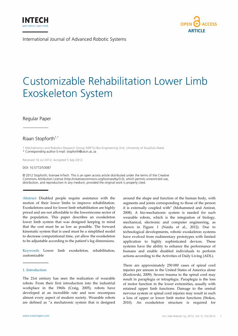
around the shape and function of the human body, with segments and joints corresponding to those of the person it is externally coupled with” (Mohammed and Amirat, 2008). A bio‐mechatronic system is needed for such wearable robots, which is the integration of biology, mechanical, electronic and computer engineering, as shown in Figure 1 (Naidu et al., 2012). Due to technological developments, robotic exoskeleton systems have evolved from rudimentary prototypes with limited application to highly sophisticated devices. These systems have the ability to enhance the performance of humans and enable disabled individuals to perform actions according to the Activities of Daily Living (ADL). There are approximately 250 000 cases of spinal cord injuries per annum in the United States of America alone (Koslowski, 2009). Severe trauma to the spinal cord may result in paraplegia or tetraplegia. Paraplegia is the loss of motor function in the lower extremities, usually with retained upper limb functions. Damage to the central nervous system or spinal cord injuries may result in such a loss of upper or lower limb motor functions (Stokes, 2010). An exoskeleton structure is required for
1Riaan Stopforth: Customizable Rehabilitation Lower Limb Exoskeleton Systemwww.intechopen.com
ARTICLE
www.intechopen.com Int J Adv Robotic Sy, 2012, Vol. 9, 152:2012
individuals wlower limbsimplementat
Figure 1. Bio‐M
The concept enhancementHowever, it wbecame a readevelopment“HARDIMANby General Eand outer excontrol schemhas been m(MohammedHybrid Assisgeneration, amodern techn HAL‐5 was dTsukuba, Japstrength augHAL‐5 is a ftwo control and “cybernecontrol schemdetection forscheme is usno viable EMpredefined m BLEEX is a developed byBerkley, in capabilities oa highly sensensors on tthe operatorthe interactiexoskeleton (
who have losts. Such an ion of the low
Mechatronics in
of using an t has been awas only receality. One of t of poN”. This full bElectric Co. in xoskeleton whme (Pons, 200major developd and Amiratstive Limb (Hand Berkley’snology.
designed by rpan. The HALgmentation anfull body exosschemes, na
etic robot contme utilizes elr augmentatiosed for repetitMG signals. motions for a s
lower limb ry researchers an effort to
of the operatonsitive controlhe exoskeleto. However, thion force be(Kazerooni, 20
t their motor injury coul
wer limb exosk
tegration conce
exoskeleton around for huently that powthe first cont
owered exobody exoskelethe 1960s, co
hich operated 08). In the laspment in exot, 2008). SystHAL), which is BLEEX, disp
researchers atL‐5 was aimednd rehabilitatskeleton whicamely “Bio‐cytrol” (Sanaki, lectromyograpon operation. tive activities This draws specific operat
robotic exoskeat the Univero improve tor. BLEEX is cl system whicon to predict here are no setween the o005).
functions in d result in keleton.
pt
for protectioundreds of ywered exoskeletributions to eoskeletons eton was desigmprising an ion a master/sst five years toskeleton systems such asis now in the play cutting
t the Universid at meeting tion requiremch is controlleybernetic con2006). The forphy (EMG) siThe latter conor when thereon a databastor (Inc, 2011).
eleton which rsity of Califothe load beacontrolled throch uses data fthe movemensensors measuoperator and
their the
on or years. etons early was gned inner slave there tems s the fifth edge
ty of both
ments. d by
ntrol” rmer ignal ntrol e are se of
was ornia, aring ough from nt of uring the
Thedesiexosconsprosrehawithcoul Thisanddesiwerto asystrequsimpare relapers
2. Bi
TheprimDegillus
Figu
ThestabTheuse rese
objectives anign, simulateskeleton sysstruction for sthetics. Thisabilitation of hin the gait cld then be bas
s paper inves mechanical signed exoskelre to develop aallow for thetem is requireuiring a systplified controshown and
tionship betwson in motion.
iological and M
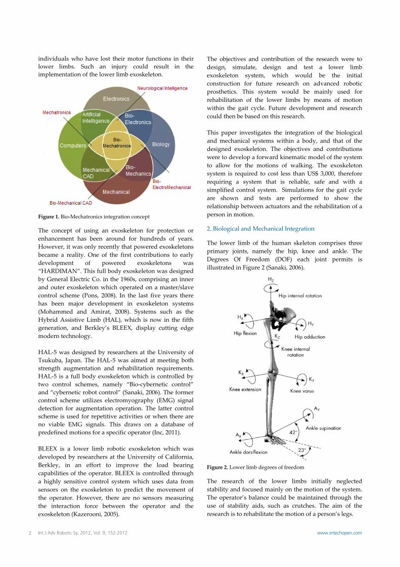
lower limb omary joints, ngrees Of Frestrated in Figu
ure 2. Lower lim
research ofbility and focu operator’s baof stability a
earch is to reha
nd contributioe, design astem, which future resea
s system wothe lower lim
cycle. Future dsed on this res
stigates the insystems withileton. The oba forward kine motions of ed to cost lesstem that is rol system. Simd tests are ween actuators.
Mechanical In
of the humannamely the heedom (DOFure 2 (Sanaki, 2
mb degrees of fre
f the lower used mainly onalance could baids, such as abilitate the m
on of the reseand test a
would be arch on advaould be mainmbs by meandevelopment earch.
ntegration of tin a body, anbjectives and ematic model walking. Thes than US$ 3,0reliable, safe mulations for performed ts and the reha
ntegration
n skeleton comhip, knee andF) each joint2006).
eedom
limbs initialn the motion obe maintainedcrutches. Th
motion of a per
earch were tolower limbthe initial
anced roboticnly used forns of motionand research
the biologicalnd that of thecontributionsof the systeme exoskeleton000, thereforeand with athe gait cycleto show theabilitation of a
mprises threed ankle. Thet permits is
lly neglectedof the system.d through thehe aim of therson’s legs.
o b l c r n h
l e s m n e a e e a
e e s
d . e e
2 Int J Adv Robotic Sy, 2012, Vol. 9, 152:2012 www.intechopen.com
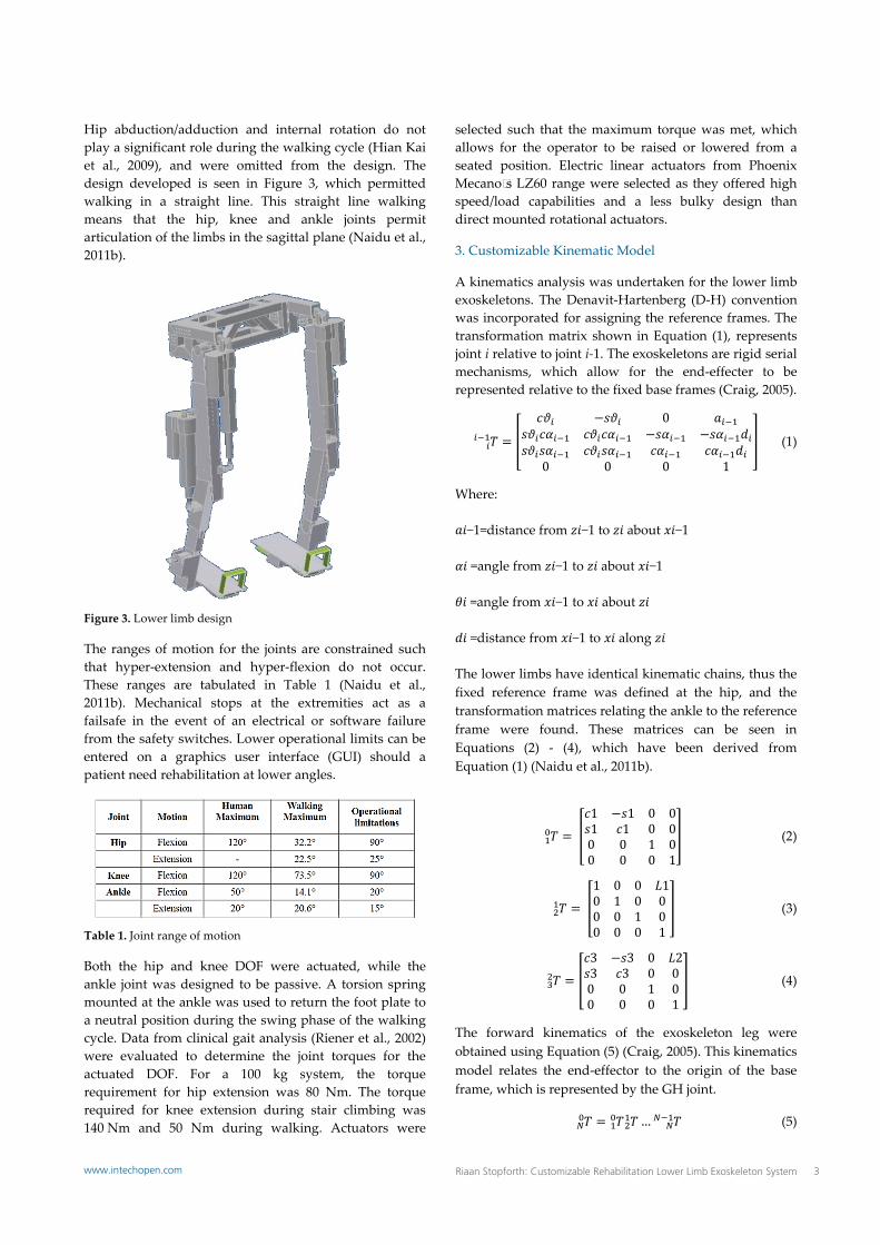
Hip abduction/adduction and internal rotation do not play a significant role during the walking cycle (Hian Kai et al., 2009), and were omitted from the design. The design developed is seen in Figure 3, which permitted walking in a straight line. This straight line walking means that the hip, knee and ankle joints permit articulation of the limbs in the sagittal plane (Naidu et al., 2011b).
Figure 3. Lower limb design
The ranges of motion for the joints are constrained such that hyper‐extension and hyper‐flexion do not occur. These ranges are tabulated in Table 1 (Naidu et al., 2011b). Mechanical stops at the extremities act as a failsafe in the event of an electrical or software failure from the safety switches. Lower operational limits can be entered on a graphics user interface (GUI) should a patient need rehabilitation at lower angles.
Table 1. Joint range of motion
Both the hip and knee DOF were actuated, while the ankle joint was designed to be passive. A torsion spring mounted at the ankle was used to return the foot plate to a neutral position during the swing phase of the walking cycle. Data from clinical gait analysis (Riener et al., 2002) were evaluated to determine the joint torques for the actuated DOF. For a 100 kg system, the torque requirement for hip extension was 80 Nm. The torque required for knee extension during stair climbing was 140 Nm and 50 Nm during walking. Actuators were
selected such that the maximum torque was met, which allows for the operator to be raised or lowered from a seated position. Electric linear actuators from Phoenix Mecano’s LZ60 range were selected as they offered high speed/load capabilities and a less bulky design than direct mounted rotational actuators.
3. Customizable Kinematic Model
A kinematics analysis was undertaken for the lower limb exoskeletons. The Denavit‐Hartenberg (D‐H) convention was incorporated for assigning the reference frames. The transformation matrix shown in Equation (1), represents joint i relative to joint i‐1. The exoskeletons are rigid serial mechanisms, which allow for the end‐effecter to be represented relative to the fixed base frames (Craig, 2005).
����� � ���� ���� 0 ����
�������� �������� ������ ���������������� �������� ����� �������0 0 0 1
� (1)
Where: ��−1=distance from ��−1 to �� about ��−1 �� =angle from ��−1 to �� about ��−1 �� =angle from ��−1 to �� about ��� �� =distance from ��−1 to �� along �� The lower limbs have identical kinematic chains, thus the fixed reference frame was defined at the hip, and the transformation matrices relating the ankle to the reference frame were found. These matrices can be seen in Equations (2) ‐ (4), which have been derived from Equation (1) (Naidu et al., 2011b).
��� � � ��1 ��1 0 0�1 �1 0 00 0 1 00 0 0 1
� (2)
��� � � �1 0 0 �10 1 0 00 0 1 00 0 0 1
� (3)
��� � ��� ��� 0 ���� �� 0 00 0 1 00 0 0 1
� (4)
The forward kinematics of the exoskeleton leg were obtained using Equation (5) (Craig, 2005). This kinematics model relates the end‐effector to the origin of the base frame, which is represented by the GH joint.
� ��� � ��� � ������� (5)
3Riaan Stopforth: Customizable Rehabilitation Lower Limb Exoskeleton Systemwww.intechopen.com
3.1 Inverse Ki
Several invewhich the Dsuperior arouDLS methodvector of thechange in Matrix is terms of the represented bend‐effector exoskeleton. represented
and
The iterationJacobian andkinematics. The JacobianThis will resand n = 4.
The change i2004).
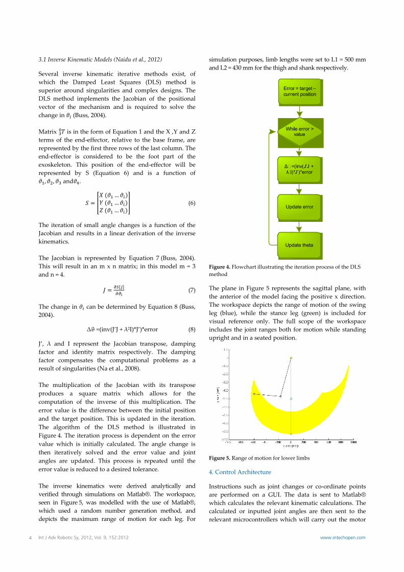
J’, λ and I factor and ifactor compresult of sing The multipliproduces a computationerror value iand the targThe algorithFigure 4. Thevalue which then iterativangles are uerror value is The inverse verified throuseen in Figurwhich used depicts the m
nematic Model
erse kinematiDamped Leaund singularid implements e mechanism(Buss, 2004).
in the form ofend‐effector, by the first thris consideredThis positioby S (Equat
d .
n of small angd results in a
n is representult in an m x
in can be d
Δϑ =(inv
represent theidentity matrpensates the gularities (Na e
ication of thsquare ma
of the inveris the differenet position. Thm of the De iteration prois initially c
vely solved aupdated. Thiss reduced to a
kinematics wugh simulationre 5, was moda random numaximum ran
s (Naidu et al.,
ic iterative mast Squares (ities and comthe Jacobian
m and is requ
f Equation 1 arelative to three rows of thd to be the on of the endtion 6) and
gle changes islinear derivat
ted by Equatix n matrix; in
etermined by
v(J’J + λ2I)*J’)*e
e Jacobian trarix respectivecomputationaet al., 2008).
e Jacobian watrix which rse of this mnce between tThis is updateDLS method ocess is depenalculated. Theand the errors process is rdesired tolera
were derivedns on Matlab®delled with thumber generange of motion
2012)
methods exist(DLS) metho
mplex designs.n of the positiuired to solve
and the X ,Y anhe base framee last column.foot part of
d‐effector wilis a function
s a function otion of the inv
ion 7 (Buss, 2this model m
Equation 8 (B
error
anspose, damly. The damal problems
with its transallows for
multiplication. the initial posed in the iterais illustrated
ndent on the ee angle changr value and repeated untilance.
d analytically ®. The worksphe use of Matlation method, n for each leg
t, of od is The ional e the
nd Z e, are . The f the ll be n of
(6)
f the verse
004). m = 3
(7)
Buss,
(8)
mping mping as a
spose the The
sition ation. d in error ge is joint l the
and pace, lab®, and
. For
simuand
Figumeth
Thethe Theleg visuincluupri
Figu
4. C
Instare whicalcrele
ulation purposL2 = 430 mm f
ure 4. Flowcharthod
plane in Figuanterior of th workspace d(blue), while
ual reference udes the jointight and in a s
ure 5. Range of m
Control Archite
ructions suchperformed onich calculates ulated or inpvant microcon
ses, limb lengtfor the thigh an
Errocurr
Wh
Δ� =λ²I)
Up
Upd
t illustrating the
ure 5 represenhe model facindepicts the ran the stance leonly. The fult ranges both seated position
motion for lowe
ecture
h as joint chann a GUI. Thethe relevant kputted joint anntrollers whic
ths were set tond shank respe
or = target –ent position
hile error > value
=(inv(J’J + )*J’)*error
date error
date theta
e iteration proce
nts the sagittang the positivnge of motioneg (green) is ll scope of thfor motion wn.
er limbs
nges or co‐ore data is senkinematic calcngles are thech will carry o
o L1 = 500 mmectively.
ess of the DLS
al plane, withve x direction.n of the swingincluded for
he workspacewhile standing
rdinate pointsnt to Matlab®culations. Then sent to theout the motor
m
h . g r e g
s ® e e r
4 Int J Adv Robotic Sy, 2012, Vol. 9, 152:2012 www.intechopen.com
control opera(Stopforth et devices. A Psystem. A Gexoskeleton models are references wallow for theFigure 6. Theback to Matla
Figure 6. Contthe exoskeleton
The microcolinear actuat1280 on an Aon the actuafeedback froinaccurate repositions, whtherefore pthemselves. shown in Fig
Figure 7. Syste
5. Tests and R
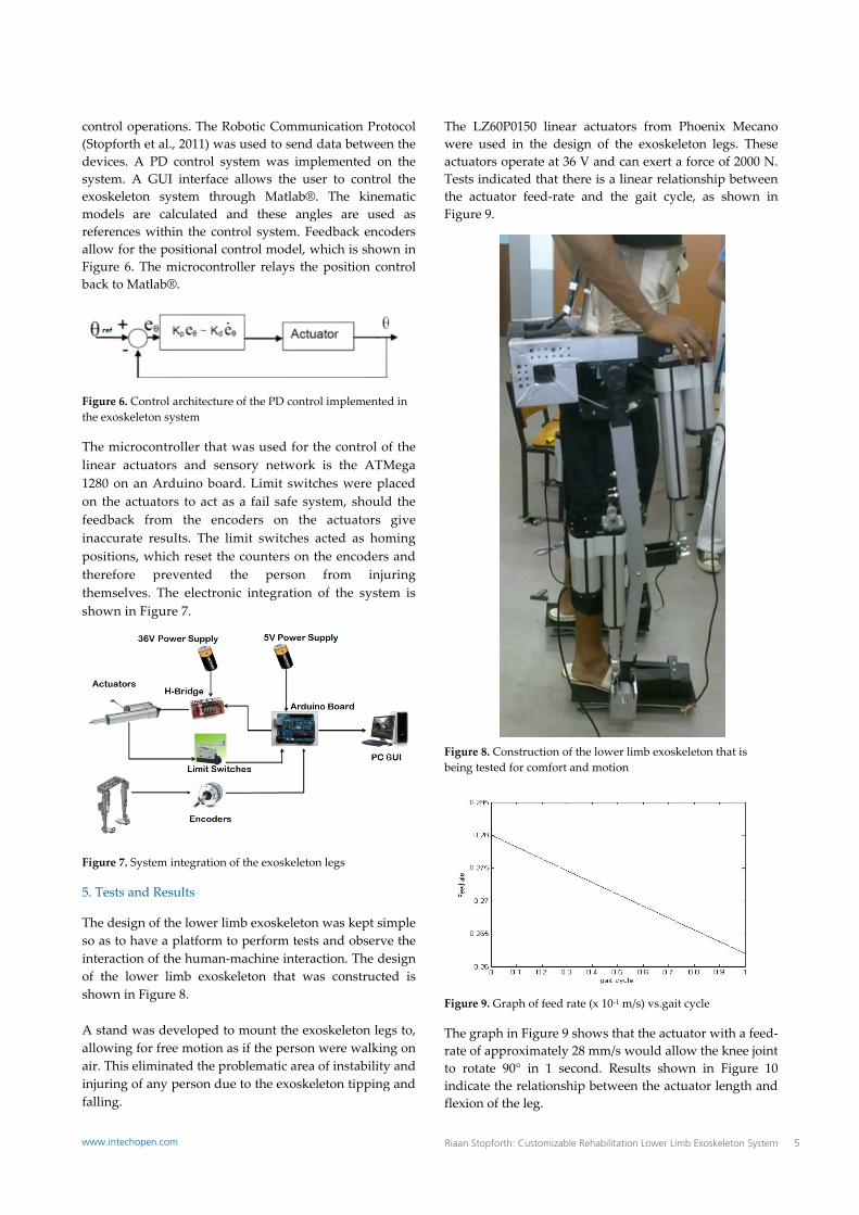
The design oso as to haveinteraction ofof the lowershown in Fig A stand was allowing for air. This eliminjuring of anfalling.
ations. The Roal., 2011) was
PD control syGUI interface system throcalculated an
within the conte positional coe microcontroab®.
trol architecturen system
ntroller that wtors and senArduino boarators to act asom the encoesults. The lihich reset theprevented tThe electronigure 7.
em integration o
Results
of the lower lime a platform tof the human‐mr limb exoskegure 8.
developed tofree motion a
minated the prony person due
obotic Commus used to sendstem was impallows the uugh Matlab®nd these angtrol system. Fontrol model, woller relays th
e of the PD contr
was used for nsory networkrd. Limit swits a fail safe syoders on thmit switches e counters on the person ic integration
of the exoskeleto
mb exoskeletoo perform testmachine interaeleton that w
o mount the exs if the personoblematic areae to the exoske
unication Protd data betweenplemented onser to control®. The kinemgles are usedFeedback encowhich is showhe position con
rol implemented
the control ok is the ATMtches were plystem, shoulde actuators acted as homthe encodersfrom inju
n of the syste
on legs
on was kept simts and observeaction. The de
was constructe
xoskeleton legn were walkina of instabilityeleton tipping
tocol n the n the l the matic d as oders wn in ntrol
d in
f the Mega laced d the give ming s and uring em is
mple e the esign ed is
gs to, ng on y and g and
TheweractuTestthe Figu
Figubein
Figu
Therateto rindiflexi
LZ60P0150 re used in theuators operatets indicated thactuator feedure 9.
ure 8. Constructing tested for com
ure 9. Graph of f
graph in Figu of approximarotate 90° in icate the relatiion of the leg.
linear actuatoe design of the at 36 V and chat there is a ld‐rate and th
ion of the lowermfort and motio
feed rate (x 10‐1
ure 9 shows thately 28 mm/s 1 second. Reionship betwe
ors from Phohe exoskeletocan exert a forlinear relationhe gait cycle,
r limb exoskeleton
m/s) vs.gait cyc
hat the actuatowould allow esults shown een the actuat
oenix Mecanon legs. Theserce of 2000 N.nship betweenas shown in
ton that is
cle
or with a feed‐the knee jointin Figure 10
tor length and
o e . n n
‐t 0 d
5Riaan Stopforth: Customizable Rehabilitation Lower Limb Exoskeleton Systemwww.intechopen.com
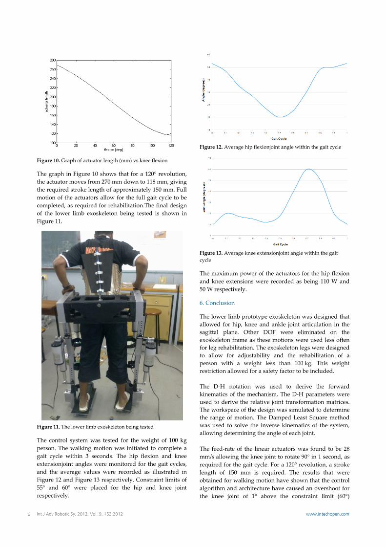
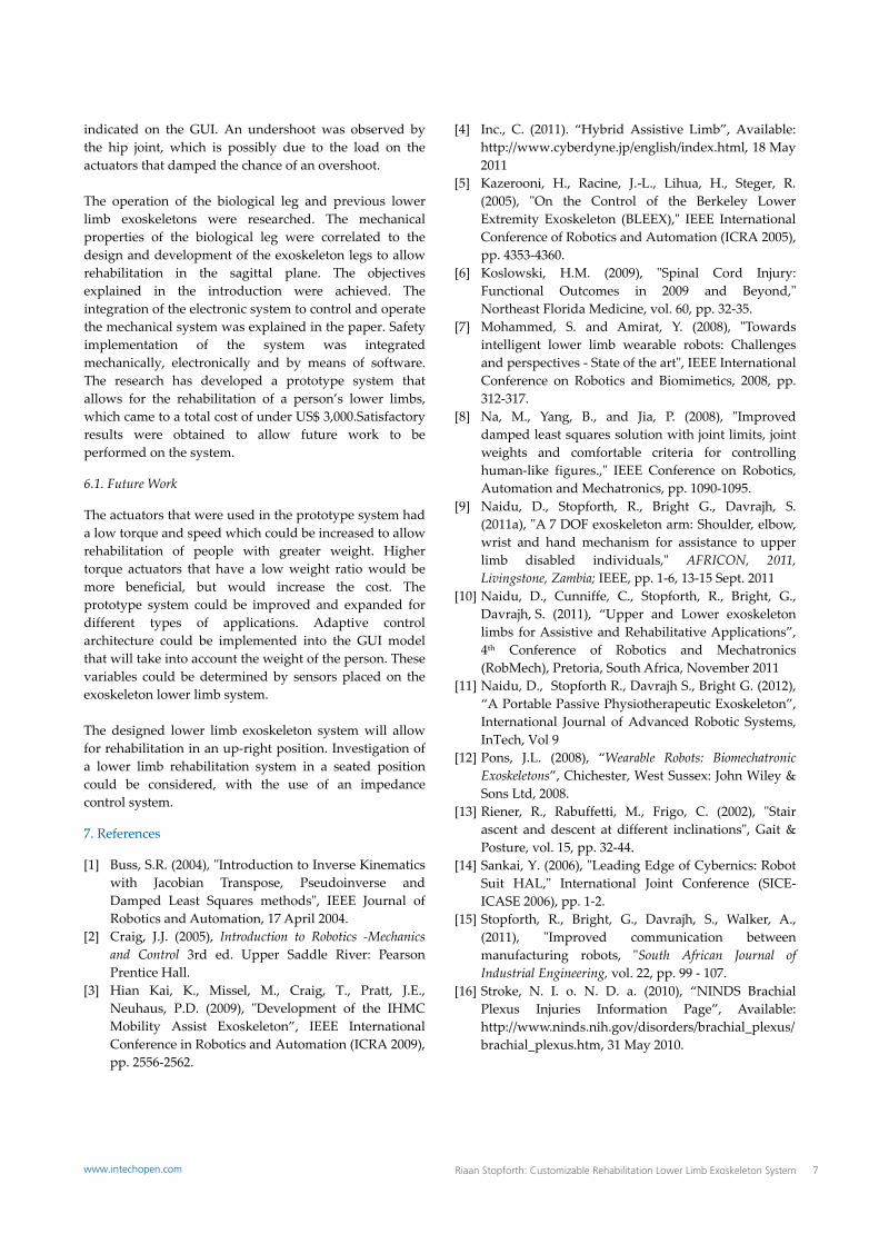
Figure 10. Gra
The graph inthe actuator mthe required motion of thcompleted, aof the lowerFigure 11.
Figure 11. The
The control person. The gait cycle wextensionjoinand the averFigure 12 an55° and 60°respectively.
ph of actuator l
n Figure 10 shmoves from 2stroke length e actuators alas required forr limb exoskel
lower limb exo
system was twalking moti
within 3 seconnt angles wererage values wd Figure 13 re° were placed
length (mm) vs.
hows that for 70 mm down of approximallow for the fur rehabilitatioleton being te
oskeleton being
tested for the ion was initiands. The hip e monitored fwere recordedespectively. Cd for the hip
knee flexion
a 120° revoluto 118 mm, giately 150 mm.ull gait cycle tn.The final deested is show
tested
weight of 10ated to compleflexion and for the gait cyd as illustrateConstraint limip and knee
ution, iving . Full to be esign wn in
00 kg ete a knee ycles, ed in its of joint
Figu
Figucycle
Theand50 W
6. C
Theallowsagiexosfor lto apersrestr ThekineusedThethe wasallow Themmrequlengobtaalgothe
ure 12. Average
ure 13. Average e
maximum po knee extensiW respectively
Conclusion
lower limb pwed for hip, ittal plane. Oskeleton framleg rehabilitatallow for adjson with a wriction allowe
D‐H notatiematics of thed to derive th workspace ofrange of mots used to solvwing determin
feed‐rate of m/s allowing thuired for the ggth of 150 mained for walkorithm and arknee joint o
hip flexionjoint
knee extensionj
ower of the acons were recoy.
prototype exosknee and ankOther DOF
me as these motion. The exoskjustability anweight less ted for a safety
on was usede mechanism. he relative joinf the design wtion. The Damve the inversening the angle
the linear acthe knee joint tgait cycle. Formm is requireking motion hchitecture havof 1° above
t angle within th
joint angle with
ctuators for thorded as bein
skeleton was kle joint articuwere eliminotions were ukeleton legs wnd the rehabithan 100 kg. factor to be in
d to derive The D‐H parnt transformawas simulatedmped Least Sqe kinematics oe of each joint
uators was foto rotate 90° inr a 120° revolued. The resulhave shown thve caused an the constrain
he gait cycle
hin the gait
he hip flexionng 110 W and
designed thatulation in thenated on thesed less oftenwere designedilitation of aThis weight
ncluded.
the forwardrameters weretion matrices.d to determinequare methodof the system,.
ound to be 28n 1 second, asution, a strokelts that werehat the controlovershoot fornt limit (60°)
n d
t e e n d a t
d e . e d ,
8 s e e l r )
6 Int J Adv Robotic Sy, 2012, Vol. 9, 152:2012 www.intechopen.com
indicated on the GUI. An undershoot was observed by the hip joint, which is possibly due to the load on the actuators that damped the chance of an overshoot. The operation of the biological leg and previous lower limb exoskeletons were researched. The mechanical properties of the biological leg were correlated to the design and development of the exoskeleton legs to allow rehabilitation in the sagittal plane. The objectives explained in the introduction were achieved. The integration of the electronic system to control and operate the mechanical system was explained in the paper. Safety implementation of the system was integrated mechanically, electronically and by means of software. The research has developed a prototype system that allows for the rehabilitation of a person’s lower limbs, which came to a total cost of under US$ 3,000.Satisfactory results were obtained to allow future work to be performed on the system.
6.1. Future Work
The actuators that were used in the prototype system had a low torque and speed which could be increased to allow rehabilitation of people with greater weight. Higher torque actuators that have a low weight ratio would be more beneficial, but would increase the cost. The prototype system could be improved and expanded for different types of applications. Adaptive control architecture could be implemented into the GUI model that will take into account the weight of the person. These variables could be determined by sensors placed on the exoskeleton lower limb system. The designed lower limb exoskeleton system will allow for rehabilitation in an up‐right position. Investigation of a lower limb rehabilitation system in a seated position could be considered, with the use of an impedance control system.
7. References
[1] Buss, S.R. (2004), ʺIntroduction to Inverse Kinematics with Jacobian Transpose, Pseudoinverse and Damped Least Squares methodsʺ, IEEE Journal of Robotics and Automation, 17 April 2004.
[2] Craig, J.J. (2005), Introduction to Robotics ‐Mechanics and Control 3rd ed. Upper Saddle River: Pearson Prentice Hall.
[3] Hian Kai, K., Missel, M., Craig, T., Pratt, J.E., Neuhaus, P.D. (2009), ʺDevelopment of the IHMC Mobility Assist Exoskeleton”, IEEE International Conference in Robotics and Automation (ICRA 2009), pp. 2556‐2562.
[4] Inc., C. (2011). “Hybrid Assistive Limb”, Available: http://www.cyberdyne.jp/english/index.html, 18 May 2011
[5] Kazerooni, H., Racine, J.‐L., Lihua, H., Steger, R. (2005), ʺOn the Control of the Berkeley Lower Extremity Exoskeleton (BLEEX),ʺ IEEE International Conference of Robotics and Automation (ICRA 2005), pp. 4353‐4360.
[6] Koslowski, H.M. (2009), ʺSpinal Cord Injury: Functional Outcomes in 2009 and Beyond,ʺ Northeast Florida Medicine, vol. 60, pp. 32‐35.
[7] Mohammed, S. and Amirat, Y. (2008), ʺTowards intelligent lower limb wearable robots: Challenges and perspectives ‐ State of the artʺ, IEEE International Conference on Robotics and Biomimetics, 2008, pp. 312‐317.
[8] Na, M., Yang, B., and Jia, P. (2008), ʺImproved damped least squares solution with joint limits, joint weights and comfortable criteria for controlling human‐like figures.,ʺ IEEE Conference on Robotics, Automation and Mechatronics, pp. 1090‐1095.
[9] Naidu, D., Stopforth, R., Bright G., Davrajh, S. (2011a), ʺA 7 DOF exoskeleton arm: Shoulder, elbow, wrist and hand mechanism for assistance to upper limb disabled individuals,ʺ AFRICON, 2011, Livingstone, Zambia; IEEE, pp. 1‐6, 13‐15 Sept. 2011
[10] Naidu, D., Cunniffe, C., Stopforth, R., Bright, G., Davrajh, S. (2011), “Upper and Lower exoskeleton limbs for Assistive and Rehabilitative Applications”, 4th Conference of Robotics and Mechatronics (RobMech), Pretoria, South Africa, November 2011
[11] Naidu, D., Stopforth R., Davrajh S., Bright G. (2012), “A Portable Passive Physiotherapeutic Exoskeleton”, International Journal of Advanced Robotic Systems, InTech, Vol 9
[12] Pons, J.L. (2008), “Wearable Robots: Biomechatronic Exoskeletons”, Chichester, West Sussex: John Wiley & Sons Ltd, 2008.
[13] Riener, R., Rabuffetti, M., Frigo, C. (2002), ʺStair ascent and descent at different inclinationsʺ, Gait & Posture, vol. 15, pp. 32‐44.
[14] Sankai, Y. (2006), ʺLeading Edge of Cybernics: Robot Suit HAL,ʺ International Joint Conference (SICE‐ICASE 2006), pp. 1‐2.
[15] Stopforth, R., Bright, G., Davrajh, S., Walker, A., (2011), ʺImproved communication between manufacturing robots, ʺSouth African Journal of Industrial Engineering, vol. 22, pp. 99 ‐ 107.
[16] Stroke, N. I. o. N. D. a. (2010), “NINDS Brachial Plexus Injuries Information Page”, Available: http://www.ninds.nih.gov/disorders/brachial_plexus/brachial_plexus.htm, 31 May 2010.
7Riaan Stopforth: Customizable Rehabilitation Lower Limb Exoskeleton Systemwww.intechopen.com