unmanned e-mag september 2015
DESCRIPTION
The Unmanned Systems E-mag brought to you by Military Embedded Systems staff covers certification and DDS, rugged Ethernet switch/router solutions, optical time-of-flight sensing technology, Thermosets’ costs and reliability advantages for auto radar PCBs.TRANSCRIPT

UNMANNEDSystems
EMAG
mil-embedded.com/topics/unmanned-systems
ñ UAS certification and DDS
ñ Thermosets’ cost and reliability
ñ Choosing a rugged Ethernet switch/router solution
ñ LeddarTech optical time-of-flight sensing technology
Sponsored by: Verocel, Isola, Curtiss-Wright Defense Solutions, LeddarTech, GE Intelligent Platforms, Annapolis Micro Systems, Sealevel
2015 Volume 2
Number 1

gedefense.com
If it’s powerful, small, lightweight and rugged you’re looking for – look no further. When space and power consumption are at a premium, but you need leading edge performance – and failure isn’t an option – we at GE have what you need.
No company knows more about acquiring, processing and delivering sensor-derived data in real time – or has more expertise in the high performance embedded computing it takes to do that.
Even better: our solutions are GERugged. You don’t get more robust reliability than that.
But it’s not just about the technology. It’s about our ability to minimize your risk, reduce your cost of development and speed your time to deployment.
Imagination at work
Get the GE Rugged app!
Watch Video

gedefense.com
If it’s powerful, small, lightweight and rugged you’re looking for – look no further. When space and power consumption are at a premium, but you need leading edge performance – and failure isn’t an option – we at GE have what you need.
No company knows more about acquiring, processing and delivering sensor-derived data in real time – or has more expertise in the high performance embedded computing it takes to do that.
Even better: our solutions are GERugged. You don’t get more robust reliability than that.
But it’s not just about the technology. It’s about our ability to minimize your risk, reduce your cost of development and speed your time to deployment.
Imagination at work
Get the GE Rugged app!

Featuring
2015 Volume 2 Number 1
Sponsored By
© 2015 OpenSystems Media, © Military Embedded Systems. All registered brands and trademarks
within the Unmanned Systems E-mag are the property of their respective owners.
UNMANNEDSystems
EMAG
Unmanned Air Systems certification and DDS
By George Romanski, Verocel, Inc.
Thermosets’ cost and reliability advantages
for auto radar PCBsBy Isola Group
Choosing a rugged Ethernet switch/router solution
By Mike Southworth, Curtiss-Wright Defense Solutions
Leddar optical time-of-flight sensing technology: a new approach to
detection and rangingBy Pierre Olivier,
LeddarTech Inc.
Above: Management protocols such as Quality of Service can be use to prioritize network traffic. Photo courtesy of Curtiss-Wright Defense Solutions.
Cover: MQ-9 unmanned aircraft system, Point Mugu, CA, July, 2015. Photo courtesy of Department of Defense (DoD)/ Lisa Ferdinando .

5
Unmanned Air Systems certification and DDS
By George Romanski, Verocel, Inc.
Thermosets’ cost and reliability advantages
for auto radar PCBsBy Isola Group
Choosing a rugged Ethernet switch/router solution
By Mike Southworth, Curtiss-Wright Defense Solutions
Leddar optical time-of-flight sensing technology: a new approach to
detection and rangingBy Pierre Olivier,
LeddarTech Inc.
Photo Credit: US Air Force
COTS and Full Custom Military Solutions
COMMUNICATE WITH CONFIDENCEThe modern battlefield demands ruggedized equipment that deliver a combat advantage. Sealevel computing and communications solutions are proven effective even in the harshest environments. Choose from an array of COTS products or partner with us to create a custom solution ideally suited to your particular application.
The Relio R2 Sync Server solid-state computer offers designers robust synchronous serial communications, small size, powerful processing, and long product life.
Perfect for radar, satellite, and other military applications, the R2 Sync Server's four synchronous ports are individually configu-rable for RS-232, RS-422, RS-485, RS-530, RS-530A or V.35. The system operates over a wide 0-50°C temperature range and is compliant to MIL-STD-810 specifications for shock and vibration.
SYNCHRONOUSCOMMUNICATIONSPOWERFUL SOLID-STATEPROCESSING
sealevel-mil.com • 864.843.4343
SL Radar eMagazine - April 15 F.pdf 1 4/8/2015 1:40:48 PM
Watch Video

6
There is a lot of activity both in industry and among certification authorities directed at the adoption of Unmanned Air Systems (UASs), also known as Drones or Unmanned Air Vehicles (UAVs). As reported in headline news, the small hobby type aircraft are already causing some problems as they are currently flown under minimal regulatory guidelines. Small professional vehicles are regulated more stringently, and the FAA is currently using Section 333 of the FAA Modernization and Reform Act as a temporary measure to govern the sector. This means that small UASs must conform to some basic rules intent on keeping them in the National Air Space (NAS) separated from other aircraft and hazards.
Unmanned Air Systems Certification and DDSBy George Romanski, Verocel, Inc.
MQ-9 unmanned aircraft system, Point Mugu, CA, July, 2015. Photo courtesy of Department of Defense (DoD)/ Lisa Ferdinando .
7
There is a range of Unmanned Air Systems with significant capabilities, range and weight that have flown for many hours using very controlled flight plans in the U.S., in foreign war-zones, and over inter-national waters. The integration of these larger UASs into the NAS means that they must share space with other aircraft and must comply with air traffic regulations, including safety regulations.
Current regulatory requirements for flying in the NAS address several classes of aircraft including Air Transport, General Aviation, Rotorcraft etc; how-ever, there are no specific regulations addressing large UASs in the U.S. at present. This limits the acceptance of UASs in the NAS for the time being.
The expectation is that as regulations for UASs are developed, they will be in-line with the existing regulations governing aircraft already flying in the NAS. Other countries have already adopted regula-tions for the development and verifica-tion of software for large UASs in their airspace. U.S. suppliers delivering UASs to Europe are already being asked to provide evidence of compliance with DO-178C (Software Considerations in Airborne Systems and Equipment Certification). It is widely accepted that the possibility of software failure is greatly reduced if that software has undergone the rigorous development and verification processes as required by DO-178C.
Software for the large UASs already flying was produced quickly to support the needs of the war-fighting effort. The
initial software architectures were built on single monolithic computer systems, or assembled using separate dedicated processors where each provided a single function. Some of this UAS software is on flying vehicles and some is on the con-trol segment, typically ground-based. Coordinating information that is shared and continuously updated between the airborne and ground-based control components is a complex task. Not only must each component send and receive information, but it must also do this within defined time limits. The compo-nents may fail for various reasons. This must be taken into account.
To improve the resilience of the UAS to total failure, its components are often designed to anticipate potential failures. They offer robustness through redun-dancy, restart/recovery, switching to safer degraded modes, and so on. This adds complexity to the UAS compo-nents and they must anticipate “unfore-seen” problems that may arise when some components are connected to other components.
Component Interconnections using DDSUAS component interconnections are complex. The interconnections may be via dedicated memory, various types of data-busses, radio or other links. The response to dropped mes-sage packets between the compo-nents could be a request for a re-trans-mission or a request for a fresh data value. A component may drop out of a network, recover, and re-establish communications. Rather than each

8
application-layer component communi-cating on a network-node making such requests, it may be expedient to use an intermediate layer to help.
The Data Distribution Service (DDS) is a middleware software developed to sup-port cooperation between a network of components. Connext DDS Cert is a DDS implementation developed by Real-Time Innovations, Inc (RTI). It supports a DDS subset that was carefully chosen to pro-vide a balance between the functionality needed and deterministic and verifiable behavior.
Safety critical UAS components may use Connext-Cert to pro-vide some of the resil-ient communication functionality they would normally have to provide themselves. This has been embraced by the UAS-Control Segment (UCS) working group by including the DDS in the approved UCS specification. An additional endorse-ment comes from the Future Aviation Capability Environment specification, which also includes DDS as a middle-ware layer.
UCS and FACE components (known as Units of Conformance in the FACE spec-ification) may be developed and veri-fied to show compliance with DO-178C independently of other components. Fortunately, Connext-Cert is available
with a Certification Data Package (CDP) from RTI, but developed by Verocel, Inc.
This CDP includes all of the information required by an auditor checking compli-ance with DO-178C at the highest level of design assurance, Level A.
Certification Data Package for a DDS implementationAs Connext-Cert is a commercial-off-the-
shelf component, there are no system require-ments for it. Instead, there is a specification of the interfaces to the software, and detailed high-level require-ments that describe the intended behavior of Connext-Cert.
As required by DO-178C, the Plan for Aspects of Certification (PSAC) document for Connext-Cert describes the approach to its certifica-tion with references to a
set of process plans, standards, design documents and other materials provided in the CDP. All low-level requirements and mapping between these and the high-level requirements are provided in the CDP, together with code, test cases, tests, test results and coverage analyses. Derived requirements (requirements introduced as part of the develop-ment process which do not trace up to higher level requirements), and Software Hazard Analysis records are provided to help the integrator perform their safety

9
analysis on the use of Connext-Cert in support of their system. The Software Accomplishment Summary (SAS) docu-ment for Connext-Cert summarizes the successful completion of all certification activities and processes as outlined in the PSAC.
All artifacts in the CDP are reviewed using documented standards and checklists. These review records are “signed-off” by the reviewer in a life-cycle traceability tool developed by Verocel called VeroTrace. VeroTrace records the identity of the developers and reviewers, checks for indepen-dence as necessary, and automates impact analysis if any artifact is changed
throughout the lifecycle. These steps taken by VeroTrace are qualified, which means that the tool’s management of the artifacts can be trusted and does not need additional manual analysis.
In addition to the lifecycle data itself, the CDP contains Configuration Management (CM) and Quality Assurance (QA) records supporting the Connext-Cert certification effort. The histories of all artifacts managed under CM control are held in the VeroTrace tool and are presented for review on the CDP. QA records resulting from audits conducted throughout the project are also present in the CDP. These audits show that the documented processes were followed, the documented criteria were satisfied, and that all of the phases and processes were completed.
Producing a CDP is an automated pro-cess using VeroTrace to structure and link many thousands of artifacts and supporting data elements such as arti-fact versions, traceability links, status information, dates, times, CM locations, and so on. Certification artifacts are managed in the VeroTrace tool and a linked dedicated CM system repository. A baseline identifier may be applied to artifacts in VeroTrace and its linked CM system at any time. Automated checks are performed to verify that VeroTrace versions align with their corresponding CM versions. The links in VeroTrace to artifacts maintained in the CM system must align perfectly. VeroTrace per-forms the consistency and completeness checks, and this functionality has been qualified. There is no need to manually
“ Verocel’s
experience is that
once the final
audit is presented,
auditors will
often search very
hard to produce a
‘finding.’”

10
review all of the relationships between these two repositories.
The baseline certification data and its links are extracted from VeroTrace and recorded on a DVD-ROM or as an ISO image. The result is an HTML based CDP that appears like a website. Information can be found in lists, can be traversed through hyperlinks, or can be searched. Forward and reverse traceability is pro-vided so that a requirement can be traced down to a design component, code, test cases, test results, and all supporting review records. Conversely, if a specific test is selected, it can be traced up to the test case it verifies, the code and the requirement. Forward and reverse traceability are present on a CDP for examination and navigation through a user’s browser.
Audit of the Certification Data PackageIn practice it is unrealistic to expect a certification auditor to review all of the artifacts and review records contained in a CDP; there are tens of thousands of them in the case of Connext-Cert. The approach usually taken by the auditors is to review the process plans very care-fully. If they are convinced that, by fol-lowing the documented processes, an acceptable CDP could be produced, they check that documented processes were actually followed. They inspect the QA records, which provide review evidence that an independent QA reviewer has checked that the engineering work was performed in accordance with the doc-umented plans and procedures. Finally, the auditors select some sample data “threads” for review. Starting at the high-est-level requirements, they follow all of
the traceability links checking the consis-tency of the associated artifacts and their reviews. They check that the documented activities were performed as expected, and they check the history records in CM. These are very detailed checks, but they are samples of the entire CDP.
The certification auditors then make a determination. If they find the threads, the process plans and the QA review evi-dence to be acceptable, then the com-plete audit is passed.
Verocel’s experience is that once the final audit is presented, auditors will often search very hard to produce a ‘finding.’ In practice, providing that good processes have been approved and followed faith-fully, these findings can almost always be fixed in a few days.
The Connext-Cert CDP has been audited a number of times. It is made available to the UCS, FACE, and other commu-nities by RTI. At Verocel, we expect Connext-Cert to be a popular compo-nent of future FACE and UCS programs as UASs are prepared for entry into the National Air Space.
George Romanski is president of Verocel, Inc.
Verocel, Inc.
www.verocel.com
Watch Video

11
Thermosets’ cost and reliability advantages for auto radar PCBs By Isola Group The car radar market for safety and driver assistance applications is exploding, and the critical mass makes the choice of PCB materials a key consideration amid the crucial importance of cost and reliability factors that are intrinsically linked to the automotive environment. So automakers are looking beyond Polytetraflouroethylene (PTFE) and highly filled hydrocarbon resins—traditionally used in high-frequency millimeter wave applications—to lower the cost of built-in vehicle radars and ensure their reliable operation at elevated temperatures. Here, the new thermoset resins are emerging as a viable alternative for advanced automotive safety systems by offering cost and reliability advantages over thermoplastic materials.
The automotive OEMs have already intro-duced radars for adaptive cruise control (ACC) and collision avoidance systems in many high-end vehicles. However, the industry drive behind connected cars and autonomous or semi-autonomous vehicles is pushing automakers to con-sider safety and driver assistance systems for a larger percentage of cars. There is even a debate about mandating some degree of automotive safety features in new vehicles.
Not surprisingly, there-fore, automotive radars are gaining attention for a variety of vehicle safety applications such as blind-spot detec-tion, pedestrian detec-tion, automatic braking, parking assistance and proximity warning. So far, short-range automo-tive radars, which sup-port most of the above
applications, have mostly been oper-ating at 24 GHz frequencies, while long-range radars for applications like adaptive cruise control go for the 77 GHz band.
However, there is a shift to higher fre-quencies of 76 to 81 GHz for both short and long-range radars for improved per-formance, smaller size and lower cost. Today’s automotive radars at 24 GHz
Rear Cross Traffic Alert
Rear Cross Traffic Alert
Side Impact
Side Impact
Lane Change Assist
Backup Aid
Lane Change Assist
BlindSpot
BlindSpot
Adaptive Cruise Control
Amazing Braking
Stop & Go
Figure 1 | The embedded radars are key to the advancement of connected cars and autonomous vehicles.

12
are rather large, while higher frequency bands like millimeter wave allow lighter radars that employ smaller boards and lower overall volumes while achieving equal or better radar performance. In addition, these smaller designs are easier to integrate into the automobile’s body contour.
Moreover, smaller PCBs allow radar OEMs to bring down the cost for the automotive safety market that is wid-ening, but also requires a competitive cost structure. Here, radar makers are increasing looking to single-board solu-tions that combine the RF and high-speed digital parts. However, such hybrid PCB designs will require RF opti-mized substrates next to low-cost FR-4 materials, and that leads to a number of manufacturability challenges.
Reliability is another key driver in advanced automotive safety systems like radars. The PCB construction should be thermally robust while showing con-sistent dielectric constant (Dk) and dissipation factor (Df) over varying humidity and temperatures ranging from -40°C to 85°C. Furthermore, automotive safety radars require larger bandwidths—up to 5 GHz—than other millimeter wave applications to acquire necessary exposure, so it’s imperative that PCB materials are consistent over the entire bandwidth.
PTFE materials, which have long been used for RF applications because of low Dk and Df, exhibit a crystalline structure that is affected by tempera-ture changes and processing steps like sintering above the melting point. The
shift in crystallinity leads to changes in effective density of PCB material, which in turn, results in changes in Dk. Moreover, PTFE materials show a highly variable coefficient of thermal expansion (CTE) that leads to high expansion at elevated temperatures.
Therefore, unlike other millimeter wave applications with more a controlled envi-ronment, such as mobile communica-tions, for automotive safety radars, PTFE shows lower yield and processing difficul-ties at elevated temperatures, especially for hybrid constructions. This article takes a look at the new thermoset materials that boast high glass transition temperatures and high thermal reliability, and shows how these advantages make thermoset a viable alternative to PTFE dielectrics for automotive radar PCBs in terms of lower cost and higher reliability.
Thermoset’s cost meritsAutomotive OEMs are challenged with reducing costs, and one way to bring down the cost is using hybrid PCB constructions, where critical layers uti-lize the highest performance materials while other board layers can use stan-dard FR-4 substrates. For such boards, PTFE materials are less desirable due to high costs, high CTE and a number of processing concerns.
For instance, PTFE uses abrasive fillers to lower CTE, and that increases the drilling costs. Such processing difficul-ties also result in limited compatibility in hybrid PCB designs. Moreover, high CTE in PTFE materials leads to critical issues such as dimensional deformation and residual stress.

13
On the other hand, ther-moset polymers feature low processing and drilling costs because they don’t require plasma de-smear and they don’t use ceramic fillers to shorten drill life. Moreover, the fact that thermoset materials use the processing standard similar to FR-4 means that all the stacks and materials can be compatible with each other, a crucial ben-efit in hybrid PCB designs.
One of the key goals in automotive design is to reduce the number of layers on the board and reduce the number of boards needed. Today, most radar applications use two boards, one for the high-speed digital processing and one for the RF circuitry. These two boards usually communicate through a con-nector, and automotive OEMs want to eliminate that connector for cost, size, and reliability reasons.
Moreover, the current PCB designs have the antenna on the outer layer using a connector, while the two boards are manufactured separately. Again, having just one board eliminates the need for the antenna connector. Automakers can significantly lower radar costs by com-bining the RF and high-speed digital processing in one board instead of two; they can put RF on one side of the stack and high-speed digital on the back.
Thermoset polymers are lower in price compared to PTFE materials. Furthermore, radar OEMs can lower the fabrication cost
by using thermosets that exhibit very low-loss material properties while offering the processing capability that is similar to an FR-4 board. The board material for ther-mosets tends to drill very nicely.
Reliability: the creep factor Another important factor that favors thermoset materials as opposed to PTFE in automotive safety applications like radars is creep rate. Creep is the per-manent deformation that occurs due to thermal expansion at higher tempera-tures. The PTFE materials exhibit creep even at room temperatures, and that makes them less desirable for automo-tive environment that commonly oper-ates at elevated temperatures.
PTFE’s high degree of plastic deforma-tion is especially a problem in the hybrid PCB designs where processing difficulties emerge while combining PTFE with the low-cost FR-4 material. Thermoset mate-rials, on the other hand, display excel-lent electrical as well thermo-mechanical
Figure 2 | Hybrid constructions allow designers to reduce cost by employing expensive PCB materials for high-performance parts like RF and high-speed digital, while they can use FR-4 for non-critical layers.

14
properties in prolonged exposures to high temperatures. Creep isn’t an issue in thermoset materials even at tempera-tures as high as 200°C.
The high dimensional stability also means that yields and reliability are higher for high-frequency radar boards oper-ating over a wide temperature range. Thermosets exhibit consistent Dk and Df over the entire radar bandwidth, and that provides consistent transmission line impedance and prevents phase distortion of RADAR transmit waveform due to fre-quency dependence on phase velocity.
There are more than 100 electronic con-trol units (ECUs) in a vehicle these days, managing nearly every aspect of vehi-cle’s operation. Not surprisingly, there-fore, reliability is a key consideration for PCB designers in safety-conscious automotive electronics. The companies like Isola Group recognize the need for a cost-effective alternative to PTFE and other commercial microwave laminate materials to better serve the reliability aspects for advanced automotive safety and driver assistance systems.
Isola has unveiled a number of glass-re-inforced thermoset materials to ensure superior thermal endurance across a wide range of elevated temperatures and thus to meet the highly demanding PCB mate-rial requirements of automotive radars.
Freescale design win Freescale Semiconductor and RFbeam Microwave have conducted PCB mate-rials evaluation for the joint develop-ment of a 77 GHz radar, and here, Isola’s high Tg thermoset material Astra MT was reviewed for RF performance and processing advantages. Astra was found to show robust electrical as well as ther-mo-mechanical performance and com-patibility with hybrid constructions.
Eventually, Astra MT material was selected for RF and antenna boards in Freescale’s automotive radar demon-stration kit. The ultra low-loss Astra MT dielectric materials have demonstrated a very high suitability for patch antenna designs and RF front-end PCBs for 76 to 81 GHz radar applications, offering a higher yield and lower production costs.
The demonstration of the Astra MT material in Freescale’s radar kit has also shown how easily thermoset polymers can be built in hybrid con-struction alongside a wide range of standard FR-4 materials to opti-mize cost. Moreover, from a reliability standpoint, Astra MT materials were thermally robust with a 200°C Tg and passed the
Figure 3 | Percent change in dielectric loss after 1,000 hours of aging at 125°C is low for high Tg thermosets.
Highly FilledHydrocarbon
OxidationResistant3.48 r18.42%
High TgThermoset
3.0 r0.61%
High TgThermoset
3.5 r2.44%
High TgThermoset
3.56 r5.41%
20
15
5
10
0

15
rigorous tests like 6X 260°C to qualify for the automotive environment.
Next up, for automotive radars oper-ating at 24 GHz, where most of the action is right now for radar applica-tions, Isola has released I-Tera MT mate-rials for RF boards. I-Tera MT boasts stable electrical properties over a broad frequency and temperature range with a Dk that is stable between -55°C and +125°C up to 20 GHz.
Moreover, it exhibits a lower Df that is stable between -55°C and +125°C for up to 20 GHz, which makes I-Tera MT a cost effective alternative to PTFE and other commercial RF and high-speed digital lam-inate materials. Thermoset polymers like Astra MT and I-Tera MT come with a full complement of laminates and prepregs to meet the diverse requirements of high-speed digital, RF and microwave designs.
Thermosets such as Astra MT and I-Tera MT fit nicely into automobile radars PCB requirements where OEMs are trying to bring down materials
cost while raising the bar for reliability because it’s important to have very high yields. These thermoset materials with performance optimized for higher fre-quencies are likely to play a crucial role in bringing the novelty of car radars to the mass market and thus help benefit a larger number of people.
Isola’s materials are used in a range of electronic end-markets including applications in computers, networking and communications equipment, high-end consumer electronics, as well as products designed for use in the advanced automotive, aerospace, military and medical markets.
Isola
www.isola-group.com
@IsolaGroup
Figure 4 | Freescale radar kit uses Isola’s Astra MT material for RF circuitry.
Watch Video

16
Fundamental questions about network architecture When systems integrators develop new platforms or modernize legacy vehicles or aircrafts, there are many fundamental questions asked about network architecture and the platform’s intended mission capabilities, which guide the selection of rugged switch and/or router Line Replaceable Units (LRU). Many of these architectural ques-tions will be addressed including:
By Mike Southworth, Curtiss-Wright Defense Solutions
Choosing a Rugged Ethernet Switch/Router Solution
Mission-critical defense and aerospace applications depend on the power and effectiveness of Ethernet networking. Rugged networking solutions come in many varieties with a host of feature options to choose from. The following article will help systems
integrators and end users explore some of the key networking capabilities available in modern Ethernet switches and router systems designed to support intra- and inter-vehicle/aircraft network architectures. The various commercial-off-the-shelf (COTS) networking systems available from Curtiss-Wright will be compared and contrasted in the context of selecting the most appropriate and capable solution to satisfy mission networking requirements.

17
õ Does the mission platform need a switch, a router, or both?
õ What is the difference between a Layer 2 and a Layer 3 device?
õ Should the network device be fully manageable or just plug-and-play?
õ What devices will be connected and how does the traffic need to be managed?
õ How many Ethernet ports and what speeds should the device support?
õ What physical media (copper or fiber optics) and connectors are most appropriate?
õ What role does size, weight, power, and cost (SWaP-C) play?
õ Is a multi-function appliance or standalone switch/router LRU a better option?
õ Is a ruggedized commercial solution or a natively rugged system a better option?
õ How can existing IT network
training and staff be leveraged to minimize support costs?
õ What environmental/EMI validation testing is required for networking devices?
õ Will the device be compatible with the aircraft generator and/or vehicle battery power input?
õ How will network security and information assurance requirements be satisfied?
Router or switch? Layer 2 or Layer 3?Ethernet switches and routers form the core of network architectures. Switches connect devices on a Local Area Network (LAN) onboard ground vehicles or air-crafts. They enable computers and sen-sors to communicate and share informa-tion locally. Connected devices might include a mission computer, flight com-puter, video camera, weapons system, Ethernet-enabled radio, or other wire-
less device. Routers form the next layer of network connec-tivity. Switches often interface with routers to share information outside the vehicle or aircraft to a Wide Area Network (WAN) via a tactical radio, satel-lite modem, or other wired or wireless back-hauls. This networking paradigm facilitates c o m m u n i c a t i o n across applications and between vehi-cles in aerospace and defense platforms.Figure 1 | OSI model of computer networking

18
The Open Systems Interconnection (OSI) model of computer networking (see figure 1: OSI model) defines “layers” of functionality which correspond to tra-ditional switch and router capabilities. Switching functionality is commonly associated with the Layer 2 data link, whereas routers are traditionally related to the Layer 3 network layer. That being said, some switches are Layer 2 and 3, providing efficient switching, as well as either static or dynamic as Internet Protocol (IP) routing capabilities. Layer 2 refers to a node-to-node frame delivery on the same link, whereas Layer 3 refers to the end-to-end (source to destination) connection including routing through intermediate hosts through optimized network protocols, such as IP.
Figure 2 highlights the corresponding OSI model layers for Curtiss-Wright’s COTS network subsystems.
Need for speed and port countDespite the traditional desire to get lightning fast connectivity and throughput, not every application real-izes tangible benefits from the faster pipes offered by 1, 10, or 40 GbE. In fact, 10/100 Fast Ethernet may meet some network requirements for WAN routing, since real-world network back-haul speeds are often slower than 100 Mbps in the field. This is because the speed of vehicle-to-vehicle platform communications is often constrained by the wireless radio connection, which becomes the bottleneck for speed and performance. Most satellite and tactical radio systems strain to achieve 5-10 Mbps throughput.
Since intra-vehicle LAN communications are not limited by the bottlenecks of a WAN connection, on-board computing devices certainly benefit from Ethernet
switches offering 1 Gigabit/second or even faster con-nectivity. Relatively fewer applications require more than 1 Gbps; however the military is increas-ingly requesting 10 GbE switches in preparation for more bandwidth intensive applica-tions, particularly those associated with high definition video surveillance, signal intelligence, radar, sonar, and high-performance commun i ca t ions Figure 2 | OSI model layers for Curtiss-Wright networking subsystems

19
systems. This trend is expected to increase as 10, 40, and 100 GbE tech-nologies mature and become more commercially available.
In terms of port density, many military vehicle applications often just require 8-10 ports; however, this is largely dependent on the platform’s concept of operations (CONOPS) and its phys-ical constraints relative to SWaP-C. With the military’s “future-proof” stance on technology insertions and the miniatur-ization of the modern networking tech-nologies, 16-20 ports seems to be the “sweet spot” for a growing number of integration programs. Due to varying program requirements, the current Curtiss-Wright COTS systems port-folio includes network subsystems that support a range of speeds from Fast Ethernet up to 10 G Ethernet connec-tivity with port counts starting at five, going up to 53 ports (see figure 3).
Copper or fiber? Connectors types?The type of physical media used for networking – typically copper or fiber optics – is another important choice that requires a balance of budget and func-tionality. Depending on the application, each has its pros and cons. Fiber optics is capable of transmitting data over long distances and providing greater data security than copper. That’s because fiber optics delivers less signal loss and is more resistant to electromagnetic interference (EMI). That being said, the bend radius of fiber optic cabling is less forgiving compared to copper and installation of optical network is often more expen-sive compared to traditional twisted pair copper wiring (e.g. CAT 5E/6), the main-stay of home and office networks. For a large majority of military and aerospace, copper media is considered a “good enough” solution. Some deployed sys-tems use both, playing to each medium’s
Figure 3 | Port count and speeds for Curtiss-Wright networking subsystems.

20
strengths: copper for onboard Gigabit Ethernet communications and fiber optic for higher-speed applications and net-work-to-network communication across considerable distance.
The type of physical network connec-tors to which the copper or optical cabling is wired is another important consideration to achieve reliable net-work connectivity onboard vehicles or aircraft. Protections against envi-ronmental factors, such as water or vibration, for example, should be con-sidered to eliminate the possibility of damage or ports becoming discon-nected. Traditional RJ-45 connectors, for example, which are found on com-mercial-grade networking equipment, are notoriously prone to failure under extreme vibration and provide very lim-ited ingress protection against dust and water. Typically an IP67-rated (dust/water proof) locking connector that rackets down or has a secure push-pull feature is recommended. Many rugged connector types abound, but the most commonly implemented approach in military and aerospace electronics appli-cation is circular MIL-DTL-38999 Series III connectors (see figure 4 – These gen-erally meet the desired requirements up to Gigabit Ethernet speeds.) Micro-miniature versions of these connectors are also now available to support lower size/weight requirements.
Where cost and size are important con-siderations, multiple Ethernet ports can be combined on a single con-nector to reduce the subsystem’s phys-ical size. Human engineering factors described in MIL-STD-1472 should also
be considered for users of networking equipment, including the spacing between connectors on the system, which can impact the ease of installing and/or removing the unit, particularly if installers are wearing gloves. For speeds of 10Gbps or more, or where signal integrity is paramount, new and specialized interconnects are becoming available within DTL-38999 connector shells and other connector types.
Figure 5 highlights the various types of connectors and media used by Curtiss-Wright networking systems.
Managed or unmanaged?Network switches come in two basic varieties, unmanaged and managed. Unmanaged switches require no con-figuration and are designed for simple plug-and-play operation. A managed switch conversely can be configured over a serial Command Line Interface (CLI) and/or Ethernet ports using a Graphical User Interface (GUI) or remote terminal application.
Figure 4 | MIL-DTL-38999 connector.

21
For some military and aerospace plat-forms, an unmanaged switch can be an ideal solution, since these are relatively easy to use and low cost. Unmanaged switches can also be ideal for scenarios where network traffic is light and the data simply needs to pass from one device to another. Rather than giving a user the ability to configure link parame-ters or prioritize network traffic, unman-aged switches “auto-negotiate” the data rate and whether to use half-du-plex or full-duplex mode. Unmanaged switches can also be helpful when a Virtual Local Area Network (VLAN) has already been defined and there’s a need to merely expand the port count on the edge of the network.
Although managed devices are more commonly installed for new technology insertions to provide the most flexibility for growth, unmanaged switches still play an important role as a piece in the overall networking architecture. Since managed switches support capabilities to shape and configure the network traffic, the device’s management software can be
critical to a platform’s mission success. The most widely used network man-agement software has been the Cisco Internetworking (Cisco IOS) software, which is accounted for in more than 50 percent of all switches and routers world-wide, according to Cisco estimates. Consequently, even non-Cisco managed network solutions are often patterned after the command line approach and capabilities introduced by Cisco.
Key management featuresBy providing users with options for mon-itoring and configuring networks, man-aged switches provide military and aero-space platforms with greater control and security over their LAN data. Maintaining situational awareness through the use of video, maps, radio, and satellite technol-ogies requires a networking infrastruc-ture that can manage and prioritize data packets to ensure mission safety and success. There are a variety of important management protocols and capabili-ties available to support such applica-tions, including Quality of Service (QoS), VLANs, Spanning Tree redundancy, and
Figure 5 | Port count and speeds for Curtiss-Wright networking subsystems

22
Simple Network Management Protocol (SNMP), among others.
QoS allows users to prioritize network traffic by assigning a higher priority to traffic from particular ports, VLANs, IP classes, tags, etc. This helps ensure con-sistent network performance for critical, time-sensitive data. QoS is especially critical for military users in a mixed-traffic environment where large data files such as map images (see figure 6) can delay important voice packets or flash messages that need to reach the vehicle operator. QoS allows the user to tag certain traffic as high priority to ensure delay-sensitive data is delivered in a timely manner.
Similarly, VLANs featured on managed switches allow connected devices to be logically grouped together and to isolate traffic between groups, even when the traffic is passing over the same physical
switch. This segmentation and isolation of network traffic helps reduce unneces-sary traffic and provides maximum band-width to devices that need to communi-cate to each other, providing better net-work performance, and in many cases, an additional level of security.
Another common feature of managed switches is support for redundancy – to safeguard a network in case a connec-tion or cable fails by providing an alter-nate data path for traffic. Many switches incorporate Spanning Tree Protocols (STP), such as RSTP or MSTP, to provide path redundancy in the network. Using spanning tree algorithms, STP allows for one active path at a time between two network devices, preventing loops and establishing the redundant links as a backup to keep integrated systems avail-able and to prevent expensive down-time. It is not uncommon for redundant flight electronics onboard manned and unmanned aircraft to be networked by Ethernet switches supporting some form of STP. In this way, onboard mission computers have multiple potential data paths and can quickly recover if critical hardware fails.
Monitoring functions of network switches via the SNMP protocol can pro-vide additional control and efficiency. SNMP facilitates the exchange of man-agement information between network devices, allowing users to determine the health of the network or the status of a particular device. This includes the number of bytes and/or frames trans-mitted and received, errors generated, and port status. By displaying this data
Figure 6 | QoS can be used to prioritize network traffic.

23
over a standard web browser, admin-istrators can monitor the performance of the network and quickly detect and repair network problems without having to physically interact with the switch.
SWaP-C in unmanned systems With shrinking government budgets and program-specific technical require-ments, there is mounting pressure on defense and aerospace contractors to provide networking solutions with reduced Size, Weight, Power, and Cost (SWaP-C). The objective is to fit as much functionality as possible in the smallest, lightest package for the least amount of money to empower the greatest efficiency and performance onboard defense and aerospace applications, including unmanned vehicles.
That being said, managing SWaP-C or “SWaP optimization” isn’t done in a vacuum without considering many other program priorities and tradeoffs that go well beyond SWaP. Program managers ultimately consider cost, performance requirements, supported feature and capabilities, reliability under extreme environments, cooling methods and thermal management, schedule and lead time constraints, use of COTS and open standards versus custom, length of life cycle management and obsolescence mitigation and scalability, among others.
SWaP reduction is a key focus at Curtiss-Wright when developing next genera-tion systems and recent advancements in technology are helping the company achieve impressive results. A noteworthy example of recent SWaP reduction is
with Parvus DuraNET Gigabit Ethernet switches. The latest model, the 20-11 (see figure 7), provides 8 ports of fully managed Gigabit Ethernet switching in an ultra-miniature form factor that is a mere 10 cubic inches in size. This rep-resents a 90 percent size reduction from the next smallest Gigabit Ethernet switch subsystem. SWaP-sensitive platforms – like unmanned air systems (UAS) are driving demand for such small network connectivity devices – and component miniaturization is helping Curtiss-Wright achieve the improvement in SWaP opti-mization. This level of miniaturization is enabling integration of LAN connectivity and more payload electronics than ever before to satisfy mission requirements. Relative size and weight comparison of Curtiss-Wright networking systems is shown in figure 9.
One newer SWaP reduction approach used by Curtiss-Wright is to consolidate networking and processor functions into a single hardware device that uses soft-ware-based networking and hypervisor
Figure 7 | Parvus DuraNET 20-11 Ultra small form.

24
virtualization applications to provide Layer 3 secure mobile routing and/or VPN encrypted security functionality (see figure 10 – This bolt-on network software approach provides the same feature sets available in dedicated hard-ware-based networking devices but in a software format that can be pre-loaded on rugged, general-purpose, x86 mis-sion computers. Logically, this software approach adds no physical size or weight to the LRU – it just utilizes some portion of the processing capabilities. The over-head from the software may not be sig-nificant for multi-core high performance systems like for the quad-core, 4th Gen
Core i7-based Parvus DuraCOR 80-41 computer (see figure 9).
Multi-function appliance vs standalone LRUNot only can combining hardware and software yield SWaP-C reduction, but also consolidating what have been tra-ditionally standalone hardware-based LRUs into a single multi-function system solution. Many military programs have begun to request subsystems that can combine network processing, Ethernet LAN switching and IP traffic routing in a single box (see Figure 10).
Figure 8 | SWaP Comparison of CW networking products.

25
Depending on the project, this can be motivated by var-ious factors, including SWaP constraints or objectives to simplify systems integration. Some programs aim to reduce the number of power supplies or cables on-board a vehicle, while others seek a solu-tion with flexible mechanical installation options. The U.S. Army’s Vehicle Integration for C4ISR/EW Interoperability (VICTORY) initiative is an excellent example of this trend, as ground vehicle architects aim to trim unnecessary fat while leveraging modern computing and networking architectures.
Open architecture, pre-integrated prod-ucts featuring modularity (mix and match functionality) are most attractive to the Department of Defense (DoD) since they do not require significant engineering expertise for customization or tailoring to program needs. To support these objectives, Curtiss-Wright has designed several scalable, rugged multi-function computing and networking subsystems based on Intel x86 or Freescale ARM processors together with various inte-grated network switch/router options, including DuraWORX products and Digital Beachhead systems.
The Parvus DuraWORX product line exemplifies this ultra-rugged multi-func-tion computing and networking system concept, combining a multi-core high performance Intel Core i7 based mis-sion processor together with a Cisco 5915 IOS-managed secure network router and optional Ethernet switch into
a single modular platform designed for extended temperature, high shock, and vibration environments. DuraWORX is a scalable, all-in-one computing appli-ance aimed at reducing SWaP and sim-plifying systems integration (thermal, cabling, power, installation) in tactical computing, IP networking and situa-tional awareness applications.
The Digital Beachhead product line includes LRUs that feature 16 ports of fully managed Layer 2 GbE switching and static Layer 3 routing together with a low-power multi-core ARM-based Freescale i.MX6 processor capable of supporting general-purpose processing requirements or optional VICTORY Data Bus Management and Shared Processor
Figure 9 | Software-based networking functionality.
Figure 10 | Parvus DuraCOR 80-41 4th Gen Core i7 Mission Computer.

26
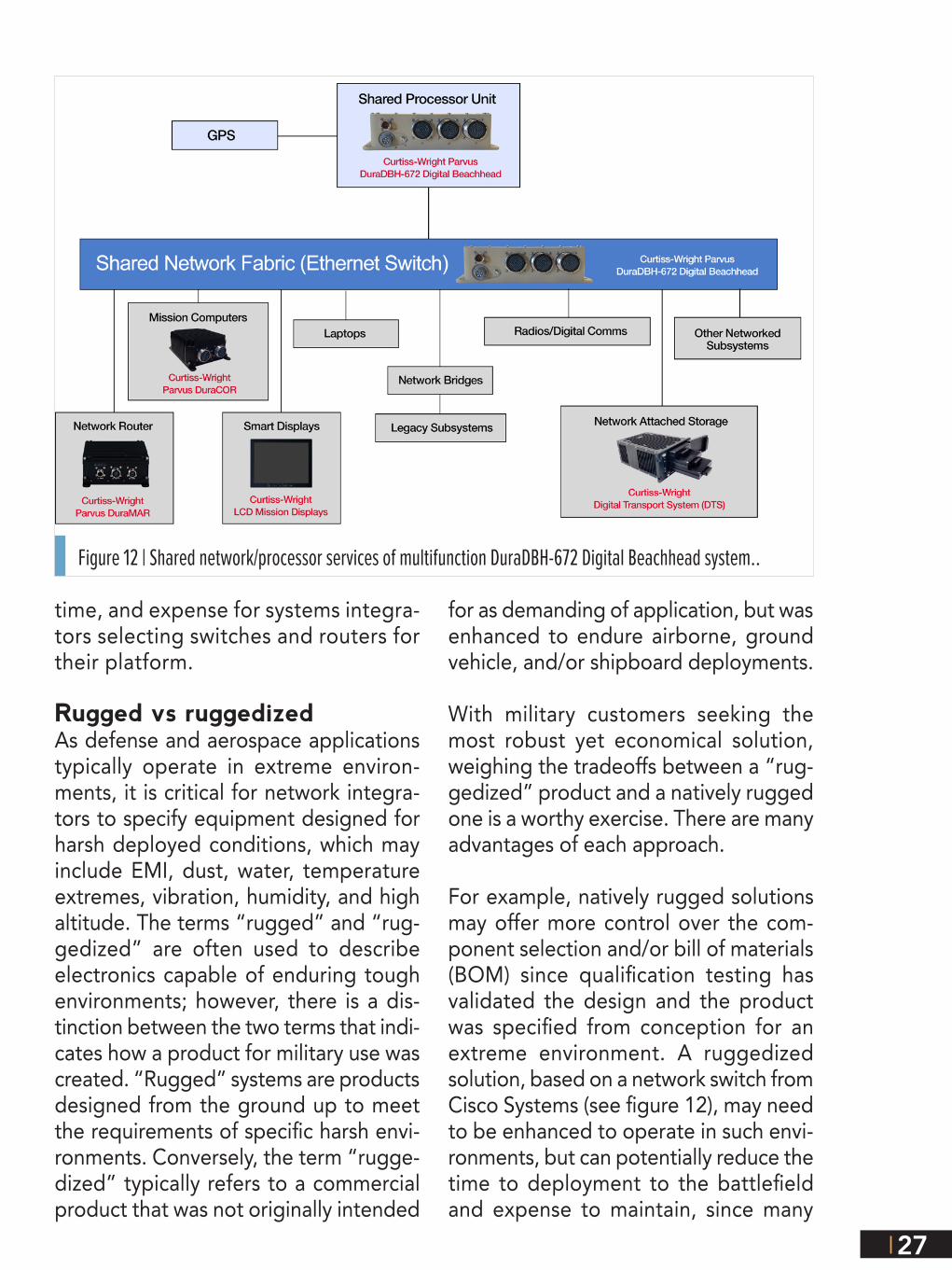
Services. These multi-function com-puting and networking devices serve as SWaP-C optimized vetronics computers with integrated network switch and GPS receiver, providing a digital backbone over Ethernet for network devices to be plugged into a vehicle and utilize CPU processing to deliver services to the platform (see figure 12).
Environmental / EMI / Power testingEthernet switches and routers intended for installation on tactical mobile plat-forms such as ground vehicles, aircraft, or maritime vessels should naturally be designed with reliability in mind, as mission effectiveness and personnel
safety can be compromised if a device fails. Validation testing should be done to either MIL-STD-810 and/or DO-160 (or equivalent) standards to qualify the equipment to specified temperature ranges, vibration frequencies, altitude, humidity offered by the device. In addi-tion, EMI testing for radiated and con-ducted emissions and susceptibility and power quality compliance testing should be performed to MIL-STD-461, MIL-STD-704, and/or MIL-STD-1275 (or equivalent) to ensure compati-bility with aircraft and vehicle voltage inputs, spikes, and transient levels. All Curtiss-Wright COTS networking prod-ucts come pre-validated to some com-bination of these tests to reduce risk,
Figure 11 | Standalone vs Multi-function networking appliance.
27
time, and expense for systems integra-tors selecting switches and routers for their platform.
Rugged vs ruggedizedAs defense and aerospace applications typically operate in extreme environ-ments, it is critical for network integra-tors to specify equipment designed for harsh deployed conditions, which may include EMI, dust, water, temperature extremes, vibration, humidity, and high altitude. The terms “rugged” and “rug-gedized” are often used to describe electronics capable of enduring tough environments; however, there is a dis-tinction between the two terms that indi-cates how a product for military use was created. “Rugged” systems are products designed from the ground up to meet the requirements of specific harsh envi-ronments. Conversely, the term “rugge-dized” typically refers to a commercial product that was not originally intended
for as demanding of application, but was enhanced to endure airborne, ground vehicle, and/or shipboard deployments.
With military customers seeking the most robust yet economical solution, weighing the tradeoffs between a “rug-gedized” product and a natively rugged one is a worthy exercise. There are many advantages of each approach.
For example, natively rugged solutions may offer more control over the com-ponent selection and/or bill of materials (BOM) since qualification testing has validated the design and the product was specified from conception for an extreme environment. A ruggedized solution, based on a network switch from Cisco Systems (see figure 12), may need to be enhanced to operate in such envi-ronments, but can potentially reduce the time to deployment to the battlefield and expense to maintain, since many
Figure 12 | Shared network/processor services of multifunction DuraDBH-672 Digital Beachhead system..

28
military personnel are already trained to operate Cisco’s network manage-ment IOS software. Consequently, sev-eral product models from Curtiss-Wright integrate natively rugged Cisco router/switch board hardware or alternatively integrate ruggedized commercial/indus-trial-grade switching hardware qualified through MIL-STD testing. In cases where performance or physical form factor cannot be satisfied with Cisco hard-ware, Curtiss-Wright also develops its own rugged hardware to meet special-ized customer requirements, including rugged 10 G switches and ultra-small form factor devices.
Leveraging IT InvestmentNetworking products need technically trained staff to operate and maintain them, which presents an opportunity for some organizations to leverage existing IT and network training invest-ment if they select products based on industry standards.
John Chambers, CEO of Cisco Systems, reported during a news interview that the company had more 70 percent market share in the U.S. government public sector. Cisco is also credited with helping to define many of today’s networking standards and protocols, actively contributing to the standards committees within the Internet Task Force, IEEE, and other groups. This per-vasiveness of Cisco technology and its IOS software makes them the “industry standard” to which more network pro-fessionals are trained. It logically fol-lows by selecting products based on Cisco technology or products that are standards-based and are “Cisco-like,” the cost to maintain and operate them should be reduced.
Security and information assuranceBeyond configurability, the information assurance for the network is another important consideration. Many Cisco-based technologies undergo information assurance validation and testing at third-party laboratories for certifications to Federal Information Processing Standard Publication 140-2 (FIPS 140-2), NAIP Common Criteria Evaluation (National Information Assurance Partnership/Common Criteria Evaluation and Validation Scheme), and/or DoD APL approval.
Network security is often achieved through a variety of secure network management protocols and authentication methods supported by switches and routers. For example, Secure Shell (SSH) and Simple Network Management Protocol (SNMP) provide encrypted administrator traffic during Telnet and SNMP sessions. TACACS+ and RADIUS authentication facilitates centralized control and restrict unauthorized users, and Dot1x, port secu-rity and DHCP allow dynamic port-based authentication. These along with intrusion
Figure 13 | Ruggedized Cisco switch, the Parvus DuraNET 3000.

29
detection firewalling, Network Address Translation (NAT), Access Control Lists (ACL), virtual local area networking, and various cryptographic technologies such as AES-256 or NSA Suite B encryption help to protect network data. Many Curtiss-Wright systems also support a non-de-structive zeroization feature to sanitize the switch or router should the platform be compromised, clearing out system firmware, as well as network addresses and configuration settings.
ConclusionDefense and aerospace integrators are expected to increasingly look to Ethernet network-based technologies to achieve fast, flexible and secure network com-munications onboard vehicles and air-craft. Advancements in throughput, man-agement capabilities, and rugged (and low SWaP) system design will give many
new options to systems integrators to achieve their network-centric operational goals. The COTS portfolio of networking solutions from Curtiss-Wright will continue to evolve to even better meet these needs and offer modern capable network solu-tions well suited for deployment at the network edge.
Mike Southworth is the Product Marketing Manager for Curtiss-Wright Defense Solutions.
Curtiss-Wright Defense Solutions
www.curtisswrightds.co
Figure 14 | Cisco technologies integrated into Curtiss-Wright rugged systems.
Watch Video

30
Leddar optical time-of-flight sensing technology: a new approach to detection and ranging
By Pierre Olivier, LeddarTech Inc.
National Optics Institute (INO) in Quebec City originally discovered Leddar optical time-of-flight sensing technology, but it was developed and commercialized by LeddarTech. It is a unique technology in the field of optical sensing. Combining fast, high-resolution analog-to-digital conversion, and innovative signal processing, Leddar light processing brings the benefits of time-domain processing to optical time-of-flight sensing.
The following will give a high-level overview of the Leddar optical time-of-flight sensing technology and its advantages compared with competing technologies. It will also describe architectural choices for sensors incorporating Leddar technology as well as the benefits that such sensors provide. Detection and ranging Remote sensing consists of acquiring information about a specific object in the vicinity of a sensor without making physical contact with the object. Countless appli-cations, including automotive driver assistance, robot guidance, traffic management, and level sensing exist for this technique.
Multiple technology options are available for remote sensing; we can divide them into three broad applications:
õ Presence or proximity detection, where the absence or presence of an object in a general area is the only information that is required (e.g., for security applications). This is the simplest form of remote sensing;
õ Speed measurement, where the exact position of an object does not need to be known but where its accurate speed is required (e.g., for law enforcement applications); and

31
õ Detection and ranging, where the position of an object relative to the sensor needs to be precisely and accurately determined.
The most complex of the three applications is the detection and ranging, and the following will focus primarily on the technologies that provide this functionality. From the position information, presence and speed can be retrieved so technol-ogies capable of detection and ranging can be universally applied to all remote sensing applications.
Although it is possible to obtain distance information with passive technologies, such as stereo triangulation of camera images, these passive technologies are usu-ally very constrained in capability. For instance, stereo triangulation requires well-de-fined edges for the matching algorithms to work. Therefore, the most commonly used technologies for measuring the position of an object involve sending energy towards the object to be measured, collecting the echo signal, and analyzing this echo signal to determine the position of one or several objects located in the sen-sor’s field of view. Since energy is intentionally emitted towards the object to be measured, we will refer to these technologies as being “active.”
Of these, some technologies rely on the geometric location of the return echo to infer position information. For instance, structured lighting involves projecting an array of dots towards the object to be measured, and analyzing the geometric dis-persion of the dots on the object using a camera and image analysis.
Other technologies rely on the time characteristic of the return echo to determine the position of the object to be measured. These are generally known as “time-of-flight measurement” technologies.
Remotesensing
Presence/Proximity
SpeedPassive Stereo Vision
Geometric Structured light
Radio
Sound
Detection and Ranging
Active
Time-of-flight
Light
Phase Detection
Range Gated Imaging
Direct Time-of Flight
Leddar
Other Direct ToF
Figure 1 | Remote sensing technologies taxonomy.

32
Although the implementa-tion differs, time-of-flight measurement can be accomplished with radio waves (radar), sound or ultrasonic waves (sonar), or light waves (lidar).
Figure 1 is a visual repre-sentation of the different remote sensing technol-ogies currently available. In the next section we will cover light-based, or optical, time-of-flight measurement technologies in more detail.
Optical time-of-flight measurement Optical time-of-flight measurement computes the distance to a target from the round-trip time of flight between a sensor and an object. Since the speed of light in air changes very little over normal temperature and pressure extremes, and its order of magnitude is faster than the speed of objects to be measured, optical time-of-flight measurement is one of the most reliable ways to accurately measure distance to objects in a contactless fashion.
Conventional optical time-of-flight sensors fall into three broad categories: direct time-of-flight, range-gated imaging, and phase detection. Leddar is a new and unique technology for performing time-of-flight measurement. This section will describe the operating principle for each measurement technology.
Direct time-of-flight measurementIn the direct time-of-flight measurement method, a discrete pulse is emitted and one or several timers are used to measure the time difference between the emitted pulse and the return echo, based on threshold detection. This time difference can be directly converted to a distance, based on the following equation:
d = (C * t) / 2
C is the speed of light, which is 299,792,458 m/s in a vacuum. The division by 2 accounts for the fact that light has to travel from the sensor to the object and then back to the sensor.
The difficulty in implementing the direct time-of-flight measurement method resides in the time intervals to be measured. In order to resolve a distance to centimeter-level accuracy, the required accuracy for the timers is 67 ps. Implemented in digital logic,
Transmit pulse
Receive echo
Start reference
Pulsethreshold
Leadingedge timer
Trailing edge

33
this would require a 15 GHz clock speed, which is obviously not practical. Therefore, various time-to-digital conversion methods are typically used.
Both edges of the pulse are commonly used to maintain accuracy independently of varying echo amplitude.
Range-gated imaging Whereas direct time-of-flight relies on measurements made on the immediate value of the received signal, range-gated imaging uses signal integration methods, typically with CCD or CMOS imagers.
By measuring the energy received in successive integration intervals, it is possible to extrapolate the distance between the sensor and the mea-sured object, based on the ratio of energy received in the dif-ferent intervals.
The difficulty with range-gated imaging is that CCD and CMOS imagers have a limited dynamic
range; therefore, strong ambient light can easily cause saturation and impair mea-surement. Furthermore, since neither the emitted and received pulses are perfect rectangle pulses, nor is the sensor perfectly linear, compensation is required and accuracy is ultimately limited.
Phase difference measurement In contrast to the previous two methods, phase difference mea-surement relies on a modulated light source and eval-uates the phase
Transmit pulse
Receive echo
Start reference
Integration Integration
Transmit signal
Receive echo
Phasedifference

34
difference between the transmit signal and the receive echo. This phase difference can be converted to distance, using the following formula:
d = (C * Ø)/ (4 * π * f)
C is the speed of light, Ø is the phase difference in radians, and f is the modulation frequency.
Correlation methods are typically used to measure the phase difference of the receive echo respective to the transmit signal as well as recover the propagation delay and therefore the distance to the object to be measured.
Of course, a phase difference greater than 2 π is not resolvable; for instance, 3 π or 5 π will be measured as a � radian phase difference. Therefore, depending on the chosen modulation frequency, an artefacting phenomenon will occur where far-away objects will appear to be much closer than in reality.
Leddar optical time-of-flight technology Leddar optical time-of-flight sensing technology is based on direct time-of-flight measurement; however, rather than working directly on the analog signal, Leddar light pro-cessing starts by sampling the receive echo for the com-
plete detection range of the sensor. Through patented methods, Leddar iteratively expands the sampling rate and resolution of this sampled signal. Finally, it analyzes the resulting discrete-time signal and recovers the distance for every object.
As opposed to the preceding methods, Leddar light processing can extract the dis-tance for every object found in the field of view.
Where the preceding methods implement detection and ranging mostly through hardware, Leddar light processing utilizes complex algorithms implemented in soft-ware. This characteristic is the key to the flexibility and performance of the technology.
Transmit pulse
Receive echo
Start reference
Object 1distance
Object 2distance

35
Through signal processing, Leddar is capable of computing an accurate distance for an object with a very weak echo. Using various advanced filters, it is also able to detect objects in the presence of nuisance signals, such as that returned by dust, snow or raindrops.
Finally, as opposed to the preceding methods, Leddar light processing can extract the distance for every object found in the field of view.
Therefore, the key advantages of Leddar technology are high sensitivity, immunity to noise, and powerful data extraction capabilities. Sensors integrating Leddar tech-nology will be able to turn these advantages into measurable benefits, as will be discussed later.
At the heart of Leddar technology is a library of signal processing functions covering four distinct stages of processing as presented in Figure 2.
The Leddar sensor Leddar is the root technology enabling the development and production of high-ef-ficiency sensor modules. Sensors incorporating Leddar optical time-of-flight tech-nology provide three key benefits compared to competing products: a high range-to-power ratio, target detection in low-visibility conditions, and the ability to resolve multiple targets. Below is a review of the key components of a Leddar-based sensor:
Figure 2 | Leddar light processing functional blocks.

36
LeddarCore Implemented in standard submicron CMOS processes, Leddar becomes an ultra-low-power sensor core (i.e., the LeddarCore) that will maxi-mize the performance of any optical time-of-flight sensor. When combined with a pho-todetector, a pulsed light source and optics, it forms a complete sensor system that can easily be integrated into a small footprint at low cost (figure 3).
Photodetector converts light pulsesThe photodetector is the com-
ponent responsible for converting light pulses into an electrical signal that can be read by the LeddarCore. Therefore, its function is key to any Leddar sensor, which can leverage various types of detectors including PIN photodiodes and APDs.
PIN Photodiode achieves long detection range Leddar technology can be used with low-cost silicon PIN photodiodes, achieving a long detection range and immunity to ambient light conditions.
The main benefit of PIN photodiodes is that the rise and fall times are very rapid (typically 10 ns or less); therefore, they are well suited for receiving short light pulses on the order of 25 ns. Furthermore, they exhibit a very high linearity, enabling very small signals to be detected even in the presence of strong incident light.
Multi-element arrays, either one- or two-dimensional, can be used to build 2-D or 3-D sensors with fast, parallel measurement and no moving parts. These sensors can be used in applications requiring rapid and accurate presence, position, or speed information.
APD enables detecting weak signalsAvalanche photodiodes can also be used. They share most of their characteristics with PIN photodiodes; however, with the use of a high reverse bias voltage (typically up to 300 V), they exhibit a current gain (typically 100 or more), enabling very weak signals to be detected.
However, one of their main drawbacks is that this gain is highly dependent on tempera-ture and bias voltage; and that bias voltage also significantly affects the dark current. Therefore, the bias voltage normally has to be adjusted depending on temperature.
Figure 3 | Main components of a Leddar sensor.
LeddarPropriety
Algorithms
LeddarCore
Integrated Circ
uit
Application/System
Pho
tode
te
ctor Light Source
Optics
Proc
essin
g Interfaces
Power
Pac
kagi
ng
IC SIGNAL PROCESSING
SENSOR MODULE
COMPLETE MODULE
INTEGRATED SOLUTION

37
Although Leddar technology has been originally developed for use with PIN or avalanche photodiodes, other types of photodetectors with sufficient bandwidth may also be used.
Light source is criticalWhereas the photodetector detects the return echo, it is the light source that is responsible for initially emitting the transmit pulse. It is therefore equally critical to the Leddar sensor.
Leddar technology can be used with visible or infrared light sources. Any light source that can generate sufficiently fast pulses can be utilized, including LEDs, lasers, or VCSELs.
LEDs as an inexpensive light sourceLEDs constitute an ideal light source for many Leddar-based applications. Moreover, the growth in LED illumination has driven the development of a large quantity of commercial light shaping components, such as collimators and reflec-tors. Furthermore, LEDs are inexpensive, available in various wavelengths, easy to assemble on printed circuit boards, and highly reliable. It is also easy to design eye-safe solutions around LEDs.
For many applications, Leddar technology can make use of a LED source that is already used for illumination or signaling. The short measurement pulses of Leddar (typically less than 50 ns) can be made imperceptible to the human eye.
Leddar is not limited to single-wavelength LEDs; white LEDs can also be used, which is particularly attractive for many smart lighting and automotive applications.
The short measurement pulses and very low duty cycle required by Leddar light processing also mean that in most cases, no specific thermal management needs to be implemented.
Lasers for maximum light requirementsPulsed laser diodes are well suited for long-range, narrow-beam applications. They are a good choice for delivering a maximum light intensity and can be colli-mated with small optics.
One drawback of pulsed laser diodes is that they have very low allowable duty cycles, limiting the measurement rate.
Figure 4 | Example of wide beam and different detection zones produced by a multi-element platform.

38
The cost per watt of laser diodes is also significantly higher than LEDs. For high-power applications, however, the footprint and the number of optical and electronic components required can be much smaller with a laser diode than with an equivalent number of LEDs.
Finally, the regulatory environment for laser products is more complex than for LED-based products; therefore, product approval and distribution for these products will be more expensive.
VCSEL comparable to edge emitting laser diodesVCSELs are a type of laser diode that emits light perpendicularly to the top surface of the wafer. They can therefore be produced at much lower cost than conven-tional, edge-emitting laser diodes. They can also be built into arrays. Therefore, they can achieve performance comparable to edge emitting laser diodes at a cost approaching LEDs.
Aside from that, the other comments on lasers stated above also apply to VCSELs.
Optics are customizable to the applicationSince Leddar is an optical technology, the field of view of a Leddar sensor can be easily tailored by selection of the source and reception optics.
Solutions ranging from a collimated beam to a 180-degree field of view can there-fore be easily designed using simple aspheric lenses.
More complex solutions can also be engineered to address specific requirements. For instance, it may be desirable for an automotive driver assistance sensor to have a longer detection range or higher resolution for the zone directly in front of the vehicle than for the sides. This is a scenario that is easily accomplishable with Leddar technology.
Benefits of Leddar technology The first benefit of Leddar optical time-of-flight sensing technology is its high range-to-power ratio. What this means is that, compared with other optical time-of-flight technologies, it can detect at a farther range with an equivalent amount of light.
This benefit can be leveraged in many different ways, depending on the target appli-cation. Compared to a sensor integrating another optical time-of-flight technology, a sensor integrating Leddar technology can:
õ Have a longer detection range with an equivalent light output; or
õ Have a similar detection range with a lower light output.

39
Another way to leverage the high range-to-power ratio of Leddar is by using a dif-fuse light source instead of a collimated source. In this case, each detection element can cover a large area. Simple optics can then be employed to customize the emis-sion and reception patterns for specific applications.
The second benefit of Leddar technology is its capability to detect targets in low-visibility conditions. Since each measurement is formed from hundreds or even thousands of discrete light pulses, the likelihood that the technology is able to obtain reliable measurements under environmental conditions such as rain, snow, or dust is very high. This is particularly true when using a diffuse light source.
Finally, the third benefit of Leddar technology is its ability to resolve multiple tar-gets with a single detector element. Once again, this benefit can be fully exploited with a diffused light source, where a small object may not fully occupy the field of view, and where the distance to background objects can be simultaneously mea-sured. Detecting multiple targets at once can represent significant added value and increased versatility for many applications. Even a single-element sensor can provide a high degree of spatial awareness.
The low-power characteristics of the technology make it suitable for mobile or por-table applications. Leddar technology is applicable to sensors starting from one detection element — and ranging up to thousands or even millions such elements.
Conclusion Backed by a decade of focused R&D, Leddar technology has reached a high level of maturity and has already been deployed in commercial solutions. With its novel, highly efficient approach to optical time-of-flight sensing, Leddar technology helps developers and integrators meet the key sensor requirements sought after for ultra-high-volume deployments: small size, low cost, low power consumption, reliability, robustness, and adaptability. With its unique characteristics, Leddar opens up an array of new possibilities in detection and ranging, and contributes to increasing efficiency, productivity, safety, or quality of life in a variety of industrial, commercial, and consumer applications.
Pierre Olivier is Vice President, Engineering and Manufacturing, of LeddarTech Inc.
LeddarTech Inc.
www.leddartech.com
[email protected] Video

SPONSORS
UNMANNEDSystems
EMAG
© 2015 OpenSystems Media, © Military Embedded Systems. All registered brands and trademarks within the Unmanned Systems E-mag are the property of their respective owners.