turboexpander: alternative fueling concept for fuel cell ... · • the turboexpander device will...
TRANSCRIPT

Turboexpander: Alternative Fueling Concept for Fuel Cell Electric Vehicle Fast Fill
Matthew Post (PI) and Daniel Leighton National Renewable Energy Laboratory April 30th , 2019
DOE Hydrogen and Fuel Cells Program 2019 Annual Merit Review and Peer Evaluation Meeting
Project ID # H2039
This presentation does not contain any proprietary, confidential, or otherwise restricted information.
Overview
Timeline and Budget
• Project start date: 10/01/18
• Project end date: 06/01/19
• Total project budget: $225K
– Total recipient share: $125K
– Total federal share: $100K
– Total DOE funds spent*: $75K
* As of 3/01/19
Delivery Technical Barriers
• Other Fueling Site/Terminal Operations
• Reliability and Costs of Gaseous Hydrogen Compression
Partners • Toyota Motor Sales
• Honda R&D Americas, Inc.
NREL | 2
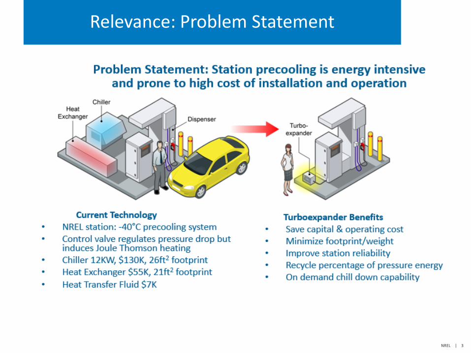
Relevance: Problem Statement
NREL | 3
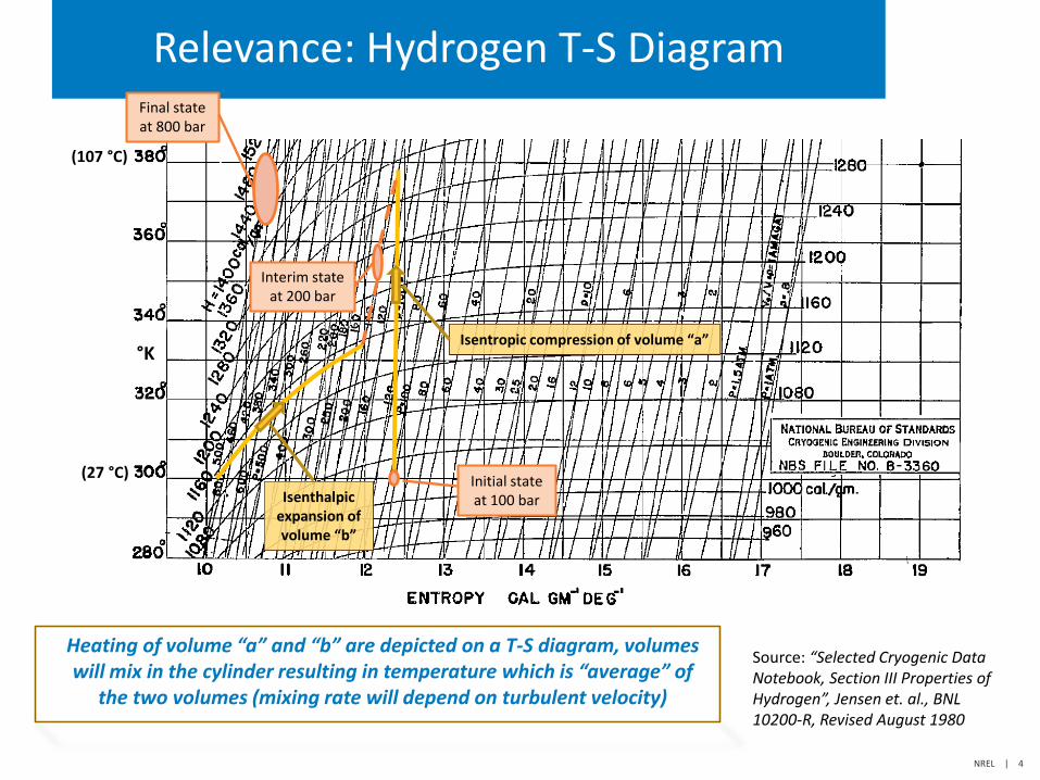
Relevance: Hydrogen T-S Diagram
Isenthalpic expansion of volume “b”
Interim state at 200 bar
Final state at 800 bar
°K
(107 °C)
(27 °C)
Isentropic compression of volume “a”
Initial state at 100 bar
Heating of volume “a” and “b” are depicted on a T-S diagram, volumes will mix in the cylinder resulting in temperature which is “average” of
the two volumes (mixing rate will depend on turbulent velocity)
Source: “Selected Cryogenic Data Notebook, Section III Properties of Hydrogen”, Jensen et. al., BNL 10200-R, Revised August 1980
NREL | 4
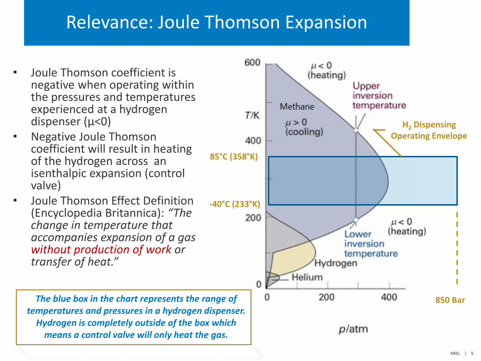
Relevance: Joule Thomson Expansion
-40°C (233°K)
85°C (358°K)
850 Bar
H2 Dispensing Operating Envelope
The blue box in the chart represents the range of temperatures and pressures in a hydrogen dispenser.
Hydrogen is completely outside of the box which means a control valve will only heat the gas.
• Joule Thomson coefficient is negative when operating within the pressures and temperatures experienced at a hydrogen dispenser (μ<0)
• Negative Joule Thomson coefficient will result in heating of the hydrogen across an isenthalpic expansion (control valve)
• Joule Thomson Effect Definition (Encyclopedia Britannica): “The change in temperature that accompanies expansion of a gas without production of work or transfer of heat.”
NREL | 5
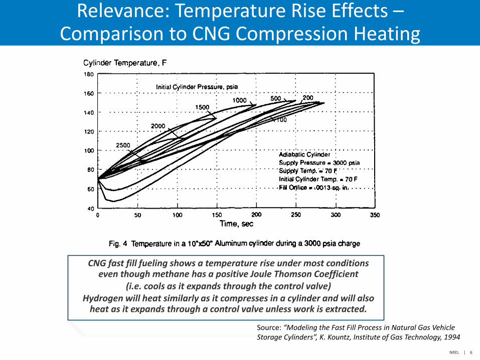
Relevance: Temperature Rise Effects – Comparison to CNG Compression Heating
CNG fast fill fueling shows a temperature rise under most conditions even though methane has a positive Joule Thomson Coefficient
(i.e. cools as it expands through the control valve) Hydrogen will heat similarly as it compresses in a cylinder and will also
heat as it expands through a control valve unless work is extracted.
Source: “Modeling the Fast Fill Process in Natural Gas Vehicle Storage Cylinders”, K. Kountz, Institute of Gas Technology, 1994
NREL | 6
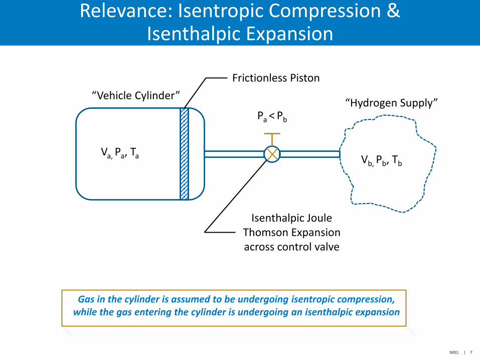
Relevance: Isentropic Compression & Isenthalpic Expansion
Frictionless Piston
“Vehicle Cylinder” “Hydrogen Supply”
Va, Pa, Ta Vb, Pb, Tb
Isenthalpic Joule Thomson Expansion across control valve
Pa < Pb
Gas in the cylinder is assumed to be undergoing isentropic compression, while the gas entering the cylinder is undergoing an isenthalpic expansion
NREL | 7
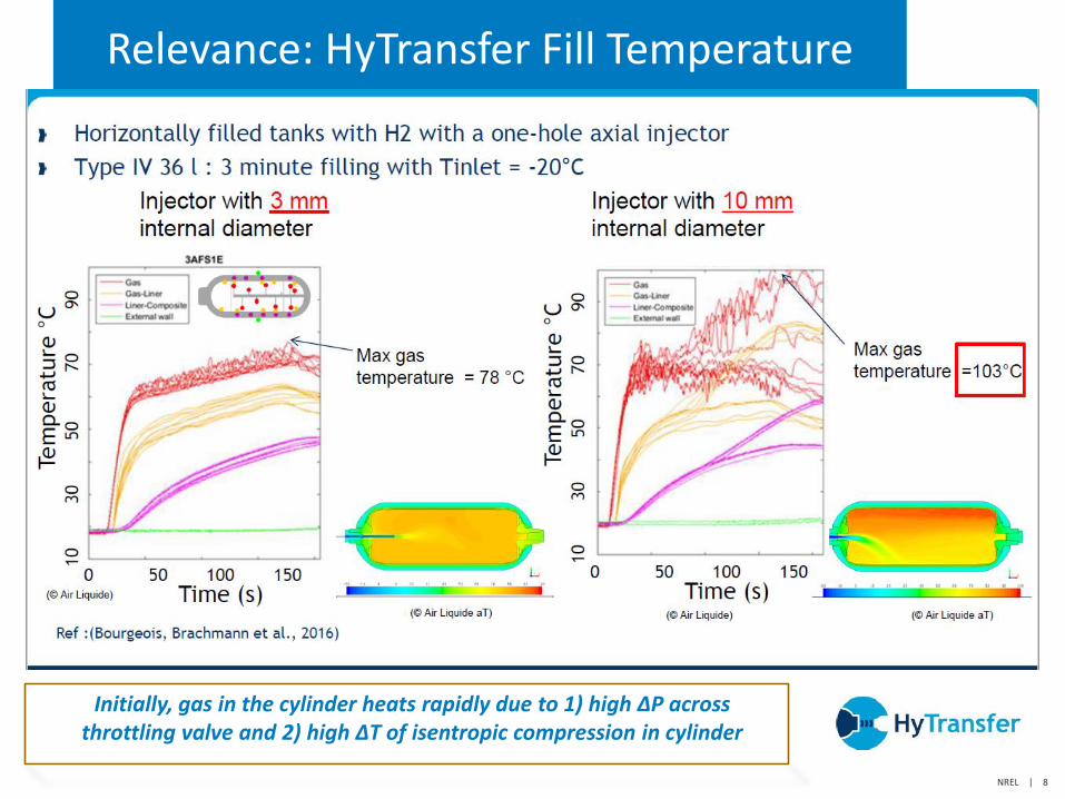
Relevance: HyTransfer Fill Temperature
Initially, gas in the cylinder heats rapidly due to 1) high ∆P across throttling valve and 2) high ∆T of isentropic compression in cylinder
NREL | 8
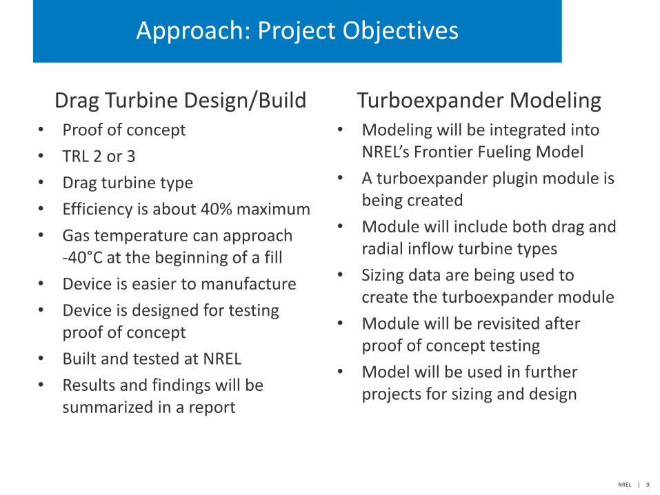
Approach: Project Objectives
Drag Turbine Design/Build • Proof of concept
• TRL 2 or 3
• Drag turbine type
• Efficiency is about 40% maximum
• Gas temperature can approach -40°C at the beginning of a fill
• Device is easier to manufacture
• Device is designed for testing proof of concept
• Built and tested at NREL
• Results and findings will be summarized in a report
Turboexpander Modeling • Modeling will be integrated into
NREL’s Frontier Fueling Model
• A turboexpander plugin module is being created
• Module will include both drag and radial inflow turbine types
• Sizing data are being used to create the turboexpander module
• Module will be revisited after proof of concept testing
• Model will be used in further projects for sizing and design
NREL | 9
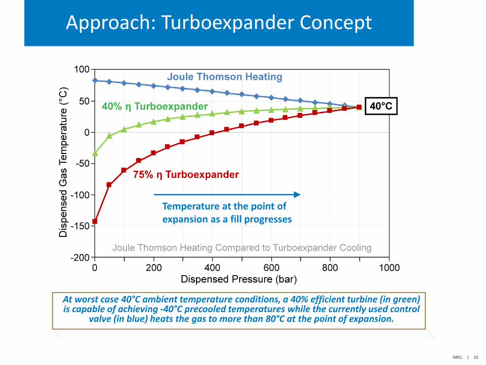
Approach: Turboexpander Concept
At worst case 40°C ambient temperature conditions, a 40% efficient turbine (in green) is capable of achieving -40°C precooled temperatures while the currently used control
valve (in blue) heats the gas to more than 80°C at the point of expansion.
Temperature at the point of expansion as a fill progresses
NREL | 10
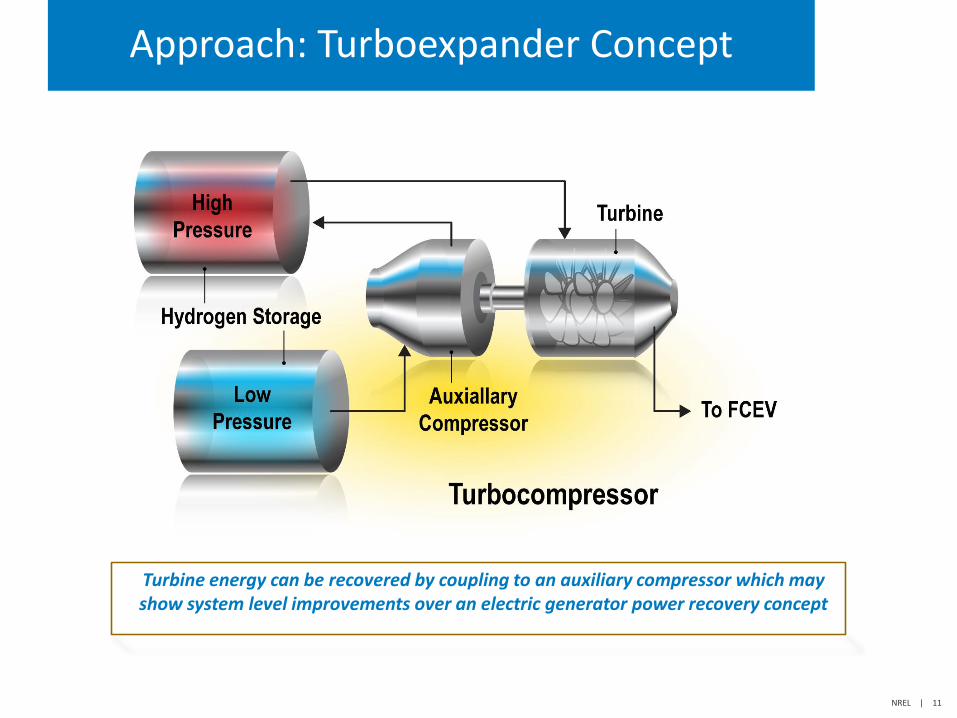
Approach: Turboexpander Concept
Turbine energy can be recovered by coupling to an auxiliary compressor which may show system level improvements over an electric generator power recovery concept
NREL | 11
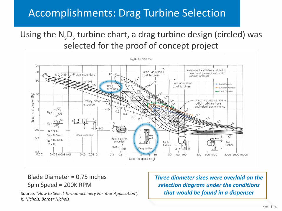
Accomplishments: Drag Turbine Selection
Using the NsDs turbine chart, a drag turbine design (circled) was selected for the proof of concept project
Blade Diameter = 0.75 inches Spin Speed = 200K RPM
Source: “How to Select Turbomachinery For Your Application”, K. Nichols, Barber Nichols
NREL | 12
Three diameter sizes were overlaid on the selection diagram under the conditions
that would be found in a dispenser
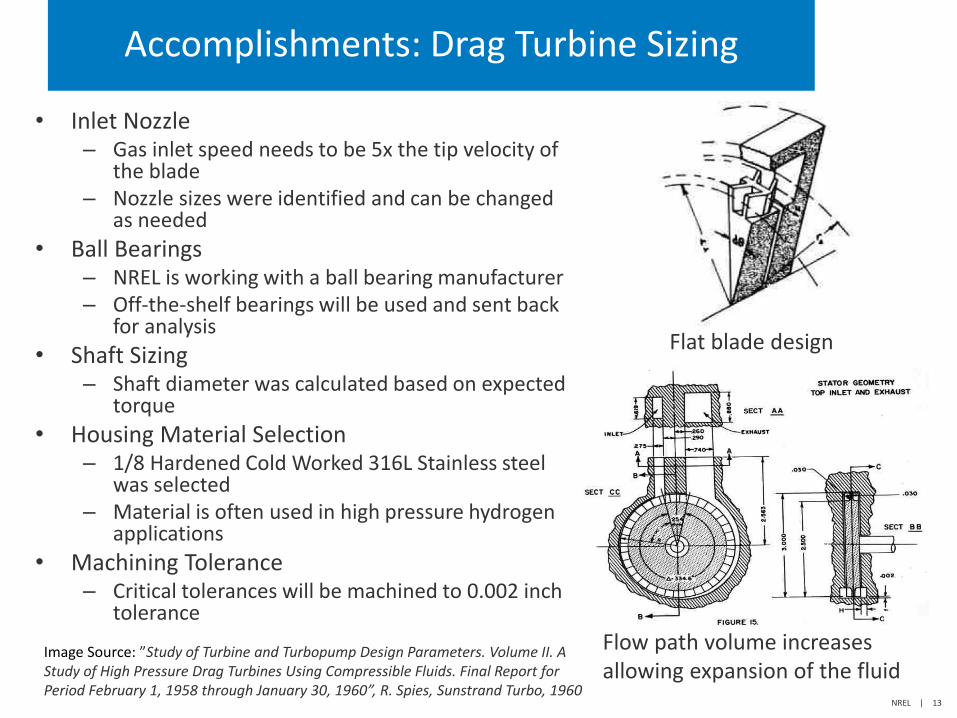
Accomplishments: Drag Turbine Sizing
• Inlet Nozzle – Gas inlet speed needs to be 5x the tip velocity of
the blade – Nozzle sizes were identified and can be changed
as needed
• Ball Bearings – NREL is working with a ball bearing manufacturer – Off-the-shelf bearings will be used and sent back
for analysis
• Shaft Sizing – Shaft diameter was calculated based on expected
torque
• Housing Material Selection – 1/8 Hardened Cold Worked 316L Stainless steel
was selected – Material is often used in high pressure hydrogen
applications
• Machining Tolerance – Critical tolerances will be machined to 0.002 inch
tolerance
Image Source: ”Study of Turbine and Turbopump Design Parameters. Volume II. A Study of High Pressure Drag Turbines Using Compressible Fluids. Final Report for Period February 1, 1958 through January 30, 1960”, R. Spies, Sunstrand Turbo, 1960
Flat blade design
Flow path volume increases allowing expansion of the fluid
NREL | 13
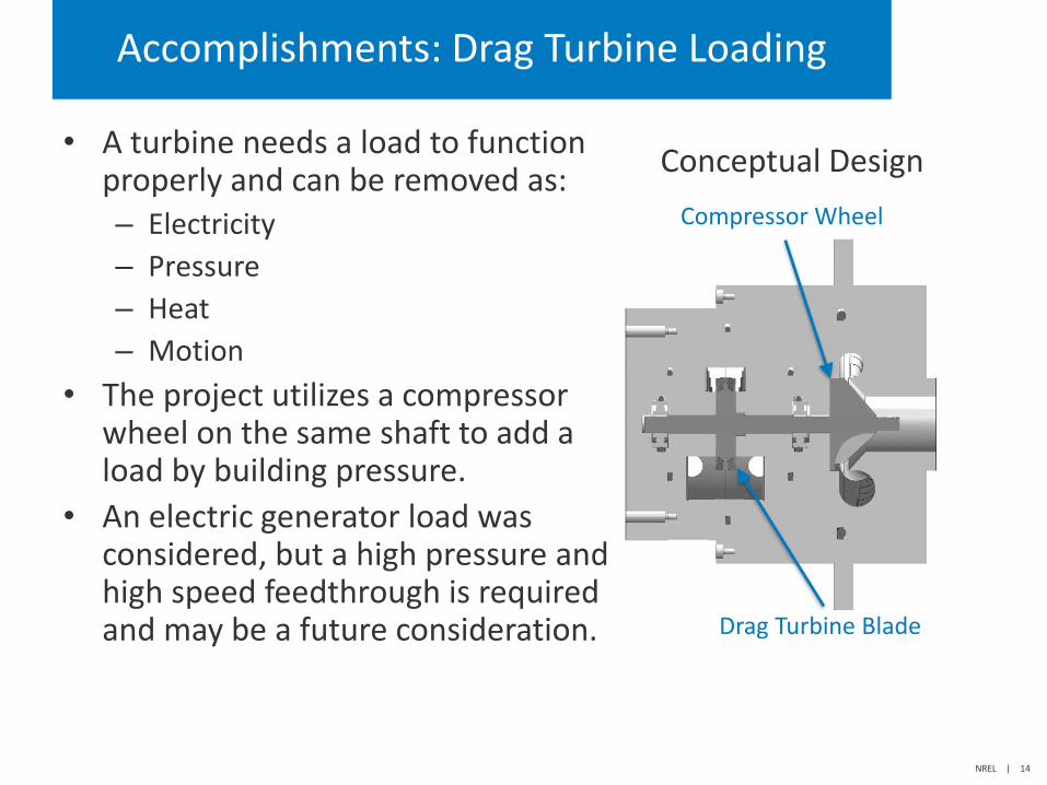
Compressor Wheel
Drag Turbine Blade
Accomplishments: Drag Turbine Loading
• A turbine needs a load to function Conceptual Design
properly and can be removed as: – Electricity
– Pressure
– Heat
– Motion
• The project utilizes a compressor wheel on the same shaft to add a load by building pressure.
• An electric generator load was considered, but a high pressure and high speed feedthrough is required and may be a future consideration.
NREL | 14
Accomplishments and Progress: Responses to Previous Year Reviewers’ Comments
• This project was not previously reviewed.
NREL | 15
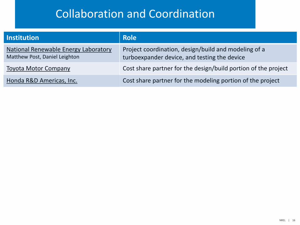
Collaboration and Coordination
Institution Role
National Renewable Energy Laboratory Matthew Post, Daniel Leighton
Project coordination, design/build and modeling of a turboexpander device, and testing the device
Toyota Motor Company Cost share partner for the design/build portion of the project
Honda R&D Americas, Inc. Cost share partner for the modeling portion of the project
NREL | 16
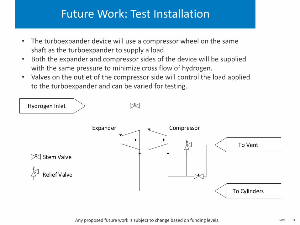
Future Work: Test Installation
• The turboexpander device will use a compressor wheel on the same shaft as the turboexpander to supply a load.
• Both the expander and compressor sides of the device will be supplied with the same pressure to minimize cross flow of hydrogen.
• Valves on the outlet of the compressor side will control the load applied to the turboexpander and can be varied for testing.
Hydrogen Inlet
To Cylinders
To Vent
Expander Compressor
Stem Valve
Relief Valve
Any proposed future work is subject to change based on funding levels. NREL | 17
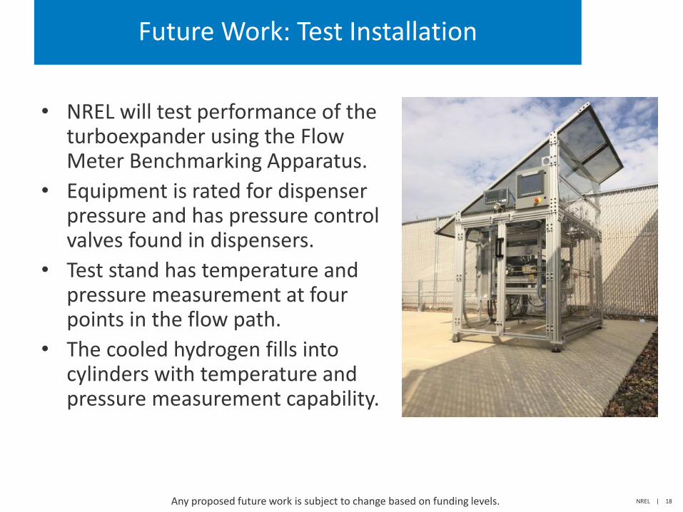
Future Work: Test Installation
• NREL will test performance of the turboexpander using the Flow Meter Benchmarking Apparatus.
• Equipment is rated for dispenser pressure and has pressure control valves found in dispensers.
• Test stand has temperature and pressure measurement at four points in the flow path.
• The cooled hydrogen fills into cylinders with temperature and pressure measurement capability.
Any proposed future work is subject to change based on funding levels. NREL | 18
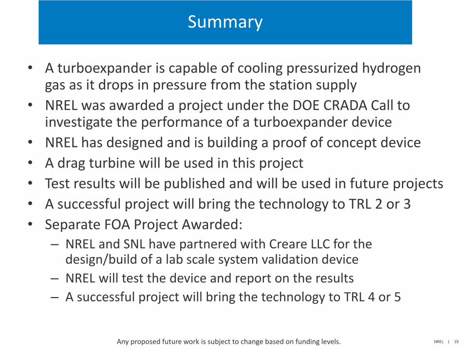
Summary
• A turboexpander is capable of cooling pressurized hydrogen gas as it drops in pressure from the station supply
• NREL was awarded a project under the DOE CRADA Call to investigate the performance of a turboexpander device
• NREL has designed and is building a proof of concept device
• A drag turbine will be used in this project
• Test results will be published and will be used in future projects
• A successful project will bring the technology to TRL 2 or 3
• Separate FOA Project Awarded: – NREL and SNL have partnered with Creare LLC for the
design/build of a lab scale system validation device
– NREL will test the device and report on the results
– A successful project will bring the technology to TRL 4 or 5
Any proposed future work is subject to change based on funding levels. NREL | 19
Thank You
www.nrel.gov
Publication Number
This work was authored in part by the National Renewable Energy Laboratory, operated by Alliance for Sustainable Energy, LLC, for the U.S. Department of Energy (DOE) under Contract No. DE-AC36-08GO28308. Sandia National Laboratories is a multi-mission laboratory managed and operated by National Technology and Engineering Solutions of Sandia, LLC., a wholly owned subsidiary of Honeywell International, Inc., for the U.S. Department of Energy’s National Nuclear Security Administration under contract DE-NA0003525. Funding provided by U.S. Department of Energy Office of Energy Efficiency and Renewable Energy Fuel Cell Technologies Office. The views expressed in the article do not necessarily represent the views of the DOE or the U.S. Government. The U.S. Government retains and the publisher, by accepting the article for publication, acknowledges that the U.S. Government retains a nonexclusive, paid-up, irrevocable, worldwide license to publish or reproduce the published form of this work, or allow others to do so, for U.S. Government purposes.

Technical Back-Up Slides
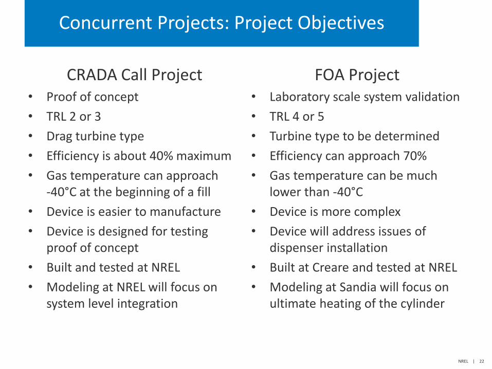
Concurrent Projects: Project Objectives
CRADA Call Project • Proof of concept
• TRL 2 or 3
• Drag turbine type
• Efficiency is about 40% maximum
• Gas temperature can approach -40°C at the beginning of a fill
• Device is easier to manufacture
• Device is designed for testing proof of concept
• Built and tested at NREL
• Modeling at NREL will focus on system level integration
FOA Project • Laboratory scale system validation
• TRL 4 or 5
• Turbine type to be determined
• Efficiency can approach 70%
• Gas temperature can be much lower than -40°C
• Device is more complex
• Device will address issues of dispenser installation
• Built at Creare and tested at NREL
• Modeling at Sandia will focus on ultimate heating of the cylinder
NREL | 22
Concurrent FOA Project: Sandia Modeling
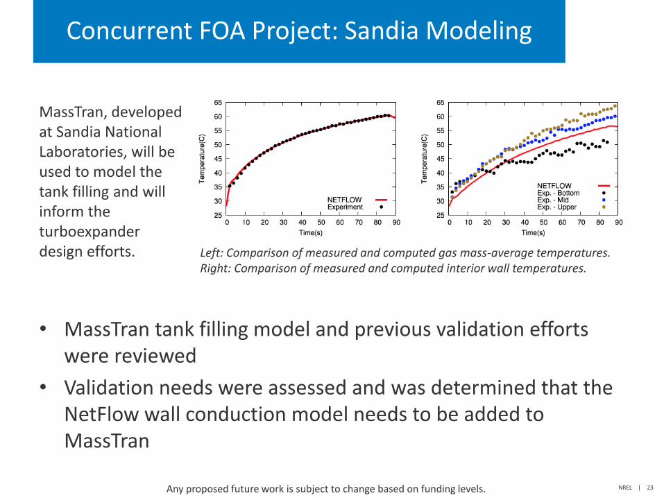
MassTran, developed at Sandia National Laboratories, will be used to model the tank filling and will inform the turboexpander design efforts.
• MassTran tank filling model and previous validation efforts were reviewed
• Validation needs were assessed and was determined that the NetFlow wall conduction model needs to be added to MassTran
NREL | 23 Any proposed future work is subject to change based on funding levels.
Left: Comparison of measured and computed gas mass-average temperatures. Right: Comparison of measured and computed interior wall temperatures.
Concurrent FOA Project: Sandia Modeling
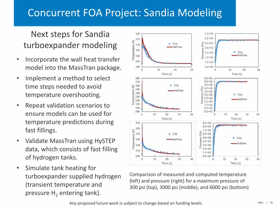
Next steps for Sandia turboexpander modeling
• Incorporate the wall heat transfer model into the MassTran package.
• Implement a method to select time steps needed to avoid temperature overshooting.
• Repeat validation scenarios to ensure models can be used for temperature predictions during fast fillings.
• Validate MassTran using HySTEP data, which consists of fast filling of hydrogen tanks.
• Simulate tank heating for turboexpander supplied hydrogen (transient temperature and pressure H2 entering tank).
NREL | 24 Any proposed future work is subject to change based on funding levels.
Comparison of measured and computed temperature (left) and pressure (right) for a maximum pressure of 300 psi (top), 3000 psi (middle), and 6000 psi (bottom)