the high pressure expander process (hpxp™) …€¦ · a second high pressure...
TRANSCRIPT
Yijun Liu, ExxonMobil Upstream Research Company
THE HIGH PRESSURE EXPANDER PROCESS (HPXP™) TECHNOLOGY
Fritz Pierre Jr., Yijun Liu, Stephanie A. Freeman, Ananda Krishna Nagavarapu, and Chuck J. Mart (ExxonMobil)
ExxonMobil Upstream Research Company
ExxonMobil has developed the High Pressure Expander Process (HPXP™) technology, a
liquefaction process using a single phase methane refrigerant operating at distinguishingly
high pressures followed by a single phase nitrogen refrigerant. HPXP™ technology has a
specific power similar to that of commercially available single mixed refrigerant (SMR)
technologies and is 10 – 25% more efficient than other expander-based technologies. The
capacity of a HPXP™ train can be double that of a SMR process and other comparable
expander-based technologies (up to 4 million tons per year) without needing parallel
equipment. The equipment count and process flow would remain essentially the same from
a small scale application of 0.5 MTA to a large scale application of 4 MTA. Integrating with
front-end heavy hydrocarbon removal unit, the technology also enables a standardized
liquefaction train design that is capable of processing a wide range of gas composition for a
given nominal train capacity. The standard design is well suited for the multiple parallel
train configurations and phased development philosophy to increase execution and
commercial efficiency.
Introduction
Since 1970, ExxonMobil has been an LNG producer and has established a strong track record of developing and
utilizing state-of-the art technology to reduce the cost of supply of LNG. These technologies reach across the LNG
value chain from gas treating, liquefaction, shipping, transfer, and regasification. Recently, ExxonMobil has been
focusing on developing technologies to decrease capital investment and increase operational efficiency to reduce
overall LNG cost of supply. Pursuing this target, ExxonMobil has developed the High Pressure Expander Process
(HPXP™) to monetize offshore and onshore gas assets. The process uses a single phase methane refrigerant
stream followed by a single phase nitrogen refrigerant, or alternatively, a recycled vaporizing LNG stream, in lieu of
conventional heavier hydrocarbon refrigerants such as ethane and propane. The process employs a significantly
higher operating pressure within the methane refrigerant stream in order to achieve the super cooling needed to
efficiently produce LNG. The elevated operating pressure allows for the HPXP™ technology to have a specific
power similar to that of commercially available single mixed refrigerant technologies (Pierre Jr, F. et al., 2018).
In comparison to other expander-based technologies, the HPXP™ technology has several advantages in efficiency
and facility design. The high efficiency of the HPXP™ technology distinguishes it from other expander-based
technologies which are 10 to 25% less efficient. In addition, the high pressure operation results in smaller
refrigerant line size and smaller refrigerant compressor casing. Furthermore, the capacity of a typical train using
the HPXP™ technology can be more than double that of other expander-based technologies (up to 4 million tons
per year) without needing parallel equipment (Pierre Jr, F. et al., 2018).
The HPXP™ technology also has several advantages when compared to mixed refrigerant (MR) technologies. The
single composition and single phase of the refrigerants simplify its operation and make the process less susceptible
to motion particularly in floating applications. Directly sourcing and making up from feed gas, the technology
eliminates not only the fractionation scope to generate MR make-up components, but also refrigerant transport,
handling, and storage of MR used in traditional liquefaction systems. The reduced hydrocarbon inventory
decreases the provisions needed to handle cryogenic spills and lowers blast loads, thereby increasing personnel
safety. The elimination of MR allows the use of a simple front-end scrubber and provides an opportunity for a
standard design capable of handling a wide range of gas composition.
The reduced equipment count and weights, decreased footprint, and smaller piping size result in CAPEX reduction.
The HPXP™ technology can also use a cold box instead of a spiral wound heat exchanger, which shortens
equipment delivery. Furthermore, this technology leverages current advances in turbo-machinery to enable high
pressure operation of this equipment. It is applicable for both offshore and onshore opportunities and presents
significant execution and operational benefits.
HPXPTM
Technology Description
HPXPTM
liquefies and sub-cools the natural gas into LNG using two closed refrigeration loops, the primary cooling
loop and the sub-cooling loop (Pierre Jr, F. et al., 2018). The technology comprises eight main process equipment
Firstname Surname, Affiliation/Company
which include two refrigerant compressor casings, three turboexpander-compressors, a single brazed aluminum
heat exchanger (BAHX) cold box, a printed circuit heat exchanger (PCHE) and a hydraulic turbine. Figure 1
provides a simplified illustration of the HPXPTM
technology.
Prior to being liquefied, the feed gas is pretreated to remove components such as carbon dioxide, sulfur
compounds, and water. The sweetened and dry feed gas is then further treated to remove the heavy hydrocarbons
which would freeze during liquefaction. It is preferable to remove the heavy hydrocarbons upstream of the main
cryogenic heat exchanger in order to maximize the production capacity and increase process flexibility. The treated
feed gas is liquefied to a temperature between -70°C to -90°C by exchanging heat with the cold methane
refrigerant of the primary cooling loop. The liquefied feed gas is then sub-cooled to a temperature below -140°C by
exchanging heat with the cold nitrogen refrigerant of the sub-cooling loop resulting in the formation of pressurized
LNG. In most applications, the pressure of the feed gas will be greater than 60 bara. Liquefying the feed gas at a
pressure above its critical point typically improves process efficiency. The pressurized LNG is letdown to a
pressure sufficiently above its bubble point using a single phase hydraulic turbine. It should be noted that the use of
hydraulic turbine for pressure letdown is not required by the HPXPTM
technology. Similar to other liquefaction
technologies, it is employed to improve process efficiency by approximately 3 to 5%, which for most applications
justifies inclusion.
The primary cooling loop is charged mostly with methane, typically at a molar concentration of greater than 90
mol%. The methane may be primarily sourced directly from the treated feed gas and optionally from LNG boil off
gas. The concentration of ethane or heavier hydrocarbons in primary cooling loop is controlled such that no liquids
form in the refrigerant stream at the cold inlet of the cold box. The primary cooling loop refrigerant is discharged
from the methane compressor at an approximate pressure of 200 bara. This elevated discharge pressure is one of
the distinguishing characteristics of the HPXPTM
technology. The high pressure methane refrigerant is cooled by
an ambient cooling heat exchanger and then is further cooled within the printed circuit heat exchanger. The
cooled high pressure methane refrigerant is isentropically expanded within two expanders configured in series to a
pressure between 30 bara to 45 bara to form the cold methane refrigerant. The cold methane refrigerant has a
temperature in the range of -75°C to -95°C depending on the desired refrigeration balance between the primary
cooling loop and the sub-cooling loop. A majority, approximately 80% to 85%, of the cold methane refrigerant is
used to liquefy the feed gas within the BAHX cores of the cold box. The remaining portion of the cold methane
refrigerant assist in the cooling the compressed nitrogen refrigerant of the sub-cooling loop. For the majority of
operating conditions, the warm methane refrigerant exiting the cold box is at a temperature sufficiently below the
ambient temperature. This available cooling duty is used to further cool the high pressure methane refrigerant
within the printed circuit heat exchanger as described earlier. The warm methane refrigerant is then compressed
using the compressors of the medium pressure turboexpander-compressor and the high pressure turboexpander-
compressor. Finally, the methane refrigerant is sent to the gas turbine driven methane compressor where it is
compressed in two stages to form the high pressure methane refrigerant, thus completing the primary cooling loop
cycle.
As Figure 1 shows, the turboexpander-compressors of the primary cooling loop are arranged in the post-boost
configuration where the turboexpander compressors are placed upstream of the gas turbine driven compressors.
Alternatively, the turboexpander-compressors can be arranged in the pre-boost configuration. The optimal
configurations can be decided based on overall optimization of compression efficiency and equipment selections.
The HPXPTM
technology is enabled by the high pressure turboexpande-compressor. The feasibility of high pressure
turboexpander-compressor, in both the post-boost and pre-boost configurations, was examined by multiple turbo-
machinery vendors. The vendors concluded that the equipment falls within their existing design methods,
machinery design configuration, and manufacturing techniques.
The sub-cooling loop is charged with nitrogen at a molar concentration of greater than 95 mol%, which is within the
concentration range provided by a typical air separation plant at most gas processing facilities. The nitrogen
refrigerant is discharged from the nitrogen compressor at a pressure near to the maximum operating pressure of
the cold box, typically below 110 bara. In contrast to the primary cooling loop, the operating conditions of the sub-
cooling loop fall within that of conventional nitrogen expander-based cycles. The compressed nitrogen refrigerant
is cooled by an ambient cooling heat exchanger. Within the cold box, the compressed nitrogen refrigerant is then
cooled to a temperature in range of -70°C to -90°C by exchanging heat with a portion of the cold methane
refrigerant and the cold nitrogen refrigerant. The cooled compressed nitrogen refrigerant is isentropically expanded
within the nitrogen turboexpander-compressor to provide the cold nitrogen refrigerant at a temperature of at least
1°C colder than the desired pressurized LNG temperature. The cold nitrogen refrigerant is used to sub-cool the
liquefied feed gas and then it is used to cool the compressed nitrogen refrigerant within the BAHX cores of the cold
box. The warm nitrogen refrigerant exiting the cold box is compressed using the compressor of the nitrogen
turboexpander-compressor. The warm nitrogen refrigerant is then sent to the gas turbine driven nitrogen
compressor where it is compressed in two stages to form the compressed nitrogen refrigerant, thus completing the
sub-cooling loop cycle. As Figure 1 shows, the nitrogen turboexpander-compressor is arranged in the post-boost
configuration in order to mirror the configuration of the primary cooling loop’s turboexpander-compressors. The
pre-boost configuration is the usual arrangement for nitrogen expander-based cycles. Either configurations can be
used for the HPXPTM
sub-cooling loop without a significant change to overall process performance. Thus, the
choice is a matter of preference.
Figure 1 shows the preferred compressor arrangement where a single gas turbine is used to drive both the primary
cooling loop compressor and the sub-cooling loop compressor. Both compressors rotate at the same speed set by
the desired discharge pressure of the primary cooling loop compressor. Alternatively, the technology has the
flexibility to balance the power between the primary cooling loop and the sub-cooling loop such that a first gas
turbine can be used to drive the primary cooling loop compressor and a second identical gas turbine, of equal
power rating as the first, can be used to drive the sub-cooling loop compressor. Although this configuration
increases gas turbine count, it provides some flexibility to optimize each compressor speed independently.
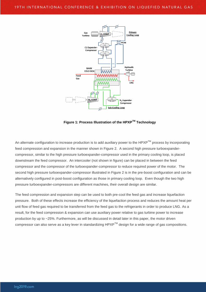
Figure 1: Process Illustration of the HPXPTM
Technology
An alternate configuration to increase production is to add auxiliary power to the HPXPTM
process by incorporating
feed compression and expansion in the manner shown in Figure 2. A second high pressure turboexpander-
compressor, similar to the high pressure turboexpander-compressor used in the primary cooling loop, is placed
downstream the feed compressor. An intercooler (not shown in figure) can be placed in between the feed
compressor and the compressor of the turboexpander-compressor to reduce required power of the motor. The
second high pressure turboexpander-compressor illustrated in Figure 2 is in the pre-boost configuration and can be
alternatively configured in post-boost configuration as those in primary cooling loop. Even though the two high
pressure turboexpander-compressors are different machines, their overall design are similar.
The feed compression and expansion step can be used to both pre-cool the feed gas and increase liquefaction
pressure. Both of these effects increase the efficiency of the liquefaction process and reduces the amount heat per
unit flow of feed gas required to be transferred from the feed gas to the refrigerants in order to produce LNG. As a
result, for the feed compression & expansion can use auxiliary power relative to gas turbine power to increase
production by up to ~25%. Furthermore, as will be discussed in detail later in this paper, the motor driven
compressor can also serve as a key lever in standardizing HPXPTM
design for a wide range of gas compositions.
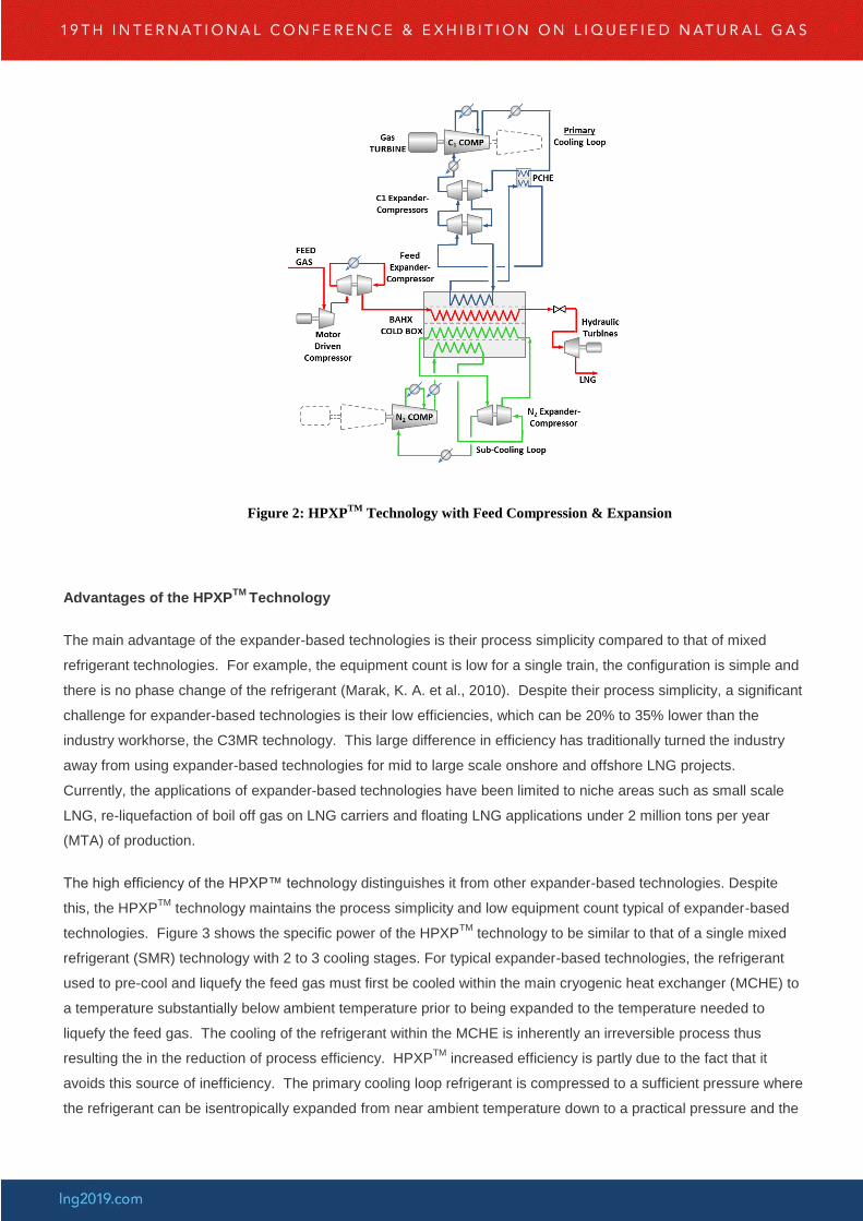
Figure 2: HPXPTM
Technology with Feed Compression & Expansion
Advantages of the HPXPTM
Technology
The main advantage of the expander-based technologies is their process simplicity compared to that of mixed
refrigerant technologies. For example, the equipment count is low for a single train, the configuration is simple and
there is no phase change of the refrigerant (Marak, K. A. et al., 2010). Despite their process simplicity, a significant
challenge for expander-based technologies is their low efficiencies, which can be 20% to 35% lower than the
industry workhorse, the C3MR technology. This large difference in efficiency has traditionally turned the industry
away from using expander-based technologies for mid to large scale onshore and offshore LNG projects.
Currently, the applications of expander-based technologies have been limited to niche areas such as small scale
LNG, re-liquefaction of boil off gas on LNG carriers and floating LNG applications under 2 million tons per year
(MTA) of production.
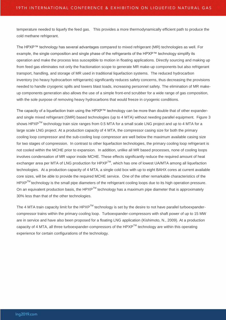
The high efficiency of the HPXP™ technology distinguishes it from other expander-based technologies. Despite
this, the HPXPTM
technology maintains the process simplicity and low equipment count typical of expander-based
technologies. Figure 3 shows the specific power of the HPXPTM
technology to be similar to that of a single mixed
refrigerant (SMR) technology with 2 to 3 cooling stages. For typical expander-based technologies, the refrigerant
used to pre-cool and liquefy the feed gas must first be cooled within the main cryogenic heat exchanger (MCHE) to
a temperature substantially below ambient temperature prior to being expanded to the temperature needed to
liquefy the feed gas. The cooling of the refrigerant within the MCHE is inherently an irreversible process thus
resulting the in the reduction of process efficiency. HPXPTM
increased efficiency is partly due to the fact that it
avoids this source of inefficiency. The primary cooling loop refrigerant is compressed to a sufficient pressure where
the refrigerant can be isentropically expanded from near ambient temperature down to a practical pressure and the
temperature needed to liquefy the feed gas. This provides a more thermodynamically efficient path to produce the
cold methane refrigerant.
The HPXP™ technology has several advantages compared to mixed refrigerant (MR) technologies as well. For
example, the single composition and single phase of the refrigerants of the HPXP™ technology simplify its
operation and make the process less susceptible to motion in floating applications. Directly sourcing and making up
from feed gas eliminates not only the fractionation scope to generate MR make-up components but also refrigerant
transport, handling, and storage of MR used in traditional liquefaction systems. The reduced hydrocarbon
inventory (no heavy hydrocarbon refrigerants) significantly reduces safety concerns, thus decreasing the provisions
needed to handle cryogenic spills and lowers blast loads, increasing personnel safety. The elimination of MR make-
up components generation also allows the use of a simple front-end scrubber for a wide range of gas composition,
with the sole purpose of removing heavy hydrocarbons that would freeze in cryogenic conditions.
The capacity of a liquefaction train using the HPXP™ technology can be more than double that of other expander-
and single mixed refrigerant (SMR) based technologies (up to 4 MTA) without needing parallel equipment. Figure 3
shows HPXPTM
technology train size ranges from 0.5 MTA for a small scale LNG project and up to 4 MTA for a
large scale LNG project. At a production capacity of 4 MTA, the compressor casing size for both the primary
cooling loop compressor and the sub-cooling loop compressor are well below the maximum available casing size
for two stages of compression. In contrast to other liquefaction technologies, the primary cooling loop refrigerant is
not cooled within the MCHE prior to expansion. In addition, unlike all MR based processes, none of cooling loops
involves condensation of MR vapor inside MCHE. These effects significantly reduce the required amount of heat
exchanger area per MTA of LNG production for HPXPTM
, which has one of lowest UA/MTA among all liquefaction
technologies. At a production capacity of 4 MTA, a single cold box with up to eight BAHX cores at current available
core sizes, will be able to provide the required MCHE service. One of the other remarkable characteristics of the
HPXPTM
technology is the small pipe diameters of the refrigerant cooling loops due to its high operation pressure.
On an equivalent production basis, the HPXPTM
technology has a maximum pipe diameter that is approximately
30% less than that of the other technologies.
The 4 MTA train capacity limit for the HPXPTM
technology is set by the desire to not have parallel turboexpander-
compressor trains within the primary cooling loop. Turboexpander-compressors with shaft power of up to 15 MW
are in service and have also been proposed for a floating LNG application (Kishimoto, N., 2009). At a production
capacity of 4 MTA, all three turboexpander-compressors of the HPXPTM
technology are within this operating
experience for certain configurations of the technology.
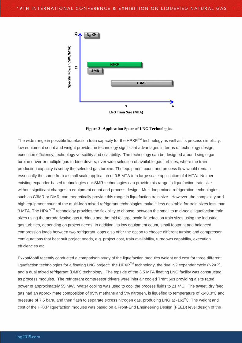
Figure 3: Application Space of LNG Technologies
The wide range in possible liquefaction train capacity for the HPXPTM
technology as well as its process simplicity,
low equipment count and weight provide the technology significant advantages in terms of technology design,
execution efficiency, technology versatility and scalability. The technology can be designed around single gas
turbine driver or multiple gas turbine drivers, over wide selection of available gas turbines, where the train
production capacity is set by the selected gas turbine. The equipment count and process flow would remain
essentially the same from a small scale application of 0.5 MTA to a large scale application of 4 MTA. Neither
existing expander-based technologies nor SMR technologies can provide this range in liquefaction train size
without significant changes to equipment count and process design. Multi-loop mixed refrigeration technologies,
such as C3MR or DMR, can theoretically provide this range in liquefaction train size. However, the complexity and
high equipment count of the multi-loop mixed refrigerant technologies make it less desirable for train sizes less than
3 MTA. The HPXPTM
technology provides the flexibility to choose, between the small to mid-scale liquefaction train
sizes using the aeroderivative gas turbines and the mid to large scale liquefaction train sizes using the industrial
gas turbines, depending on project needs. In addition, its low equipment count, small footprint and balanced
compression loads between two refrigerant loops also offer the option to choose different turbine and compressor
configurations that best suit project needs, e.g. project cost, train availability, turndown capability, execution
efficiencies etc.
ExxonMobil recently conducted a comparison study of the liquefaction modules weight and cost for three different
liquefaction technologies for a floating LNG project: the HPXPTM
technology, the dual N2 expander cycle (N2XP),
and a dual mixed refrigerant (DMR) technology. The topside of the 3.5 MTA floating LNG facility was constructed
as process modules. The refrigerant compressor drivers were inlet air cooled Trent 60s providing a site rated
power of approximately 55 MW. Water cooling was used to cool the process fluids to 21.4°C. The sweet, dry feed
gas had an approximate composition of 95% methane and 5% nitrogen, is liquefied to temperature of -148.3°C and
pressure of 7.5 bara, and then flash to separate excess nitrogen gas, producing LNG at -162oC. The weight and
cost of the HPXP liquefaction modules was based on a Front-End Engineering Design (FEED) level design of the
modules. The weight and cost of the N2XP and DMR liquefaction modules was based on scaled values from a
FEED level design of the modules for the technologies.
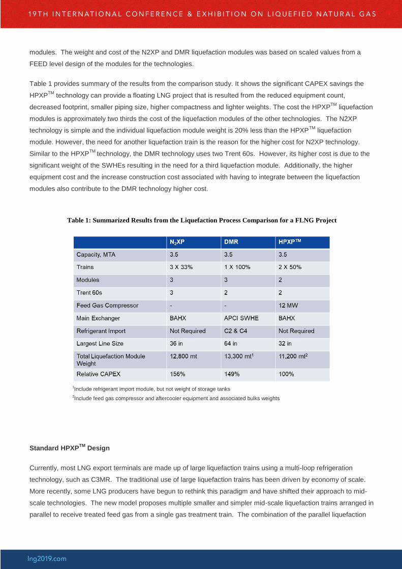
Table 1 provides summary of the results from the comparison study. It shows the significant CAPEX savings the
HPXPTM
technology can provide a floating LNG project that is resulted from the reduced equipment count,
decreased footprint, smaller piping size, higher compactness and lighter weights. The cost the HPXPTM
liquefaction
modules is approximately two thirds the cost of the liquefaction modules of the other technologies. The N2XP
technology is simple and the individual liquefaction module weight is 20% less than the HPXPTM
liquefaction
module. However, the need for another liquefaction train is the reason for the higher cost for N2XP technology.
Similar to the HPXPTM
technology, the DMR technology uses two Trent 60s. However, its higher cost is due to the
significant weight of the SWHEs resulting in the need for a third liquefaction module. Additionally, the higher
equipment cost and the increase construction cost associated with having to integrate between the liquefaction
modules also contribute to the DMR technology higher cost.
Table 1: Summarized Results from the Liquefaction Process Comparison for a FLNG Project
1Include refrigerant import module, but not weight of storage tanks
2Include feed gas compressor and aftercooler equipment and associated bulks weights
Standard HPXPTM
Design
Currently, most LNG export terminals are made up of large liquefaction trains using a multi-loop refrigeration
technology, such as C3MR. The traditional use of large liquefaction trains has been driven by economy of scale.
More recently, some LNG producers have begun to rethink this paradigm and have shifted their approach to mid-
scale technologies. The new model proposes multiple smaller and simpler mid-scale liquefaction trains arranged in
parallel to receive treated feed gas from a single gas treatment train. The combination of the parallel liquefaction
trains and the gas treatment train is now taken to be a single LNG train. This type of LNG train is now thought to
provide a cheaper and faster way to get LNG to market compared to the conventional LNG train comprising a
single, large liquefaction train. Diocee et al. discusses many of the benefits of this new approach including more
efficient project execution and increase plant availability (Diocee, T. et al., 2009). However, a question remains on
what is the right production capacity for the liquefaction trains. The right production capacity, of course, may be
specific to each LNG project. For example, should a 7.8 MTA LNG train, be designed as three 2.6 MTA
liquefaction trains or as five 1.56 MTA liquefaction trains? Regardless, the HPXPTM
technology provides a wide
range of train sizes while maintaining process simplicity and low equipment count, giving the LNG producer the
opportunity to optimize between liquefaction train size and number of trains.
What makes HPXPTM
technology particularly suitable for multiple parallel train configurations is its potential for
standardization for a wide range of feed gas composition. As discussed previously and shown in Figure 2, the feed
compressor and expansion step act to increase both the efficiency and production capacity of the HPXPTM
train.
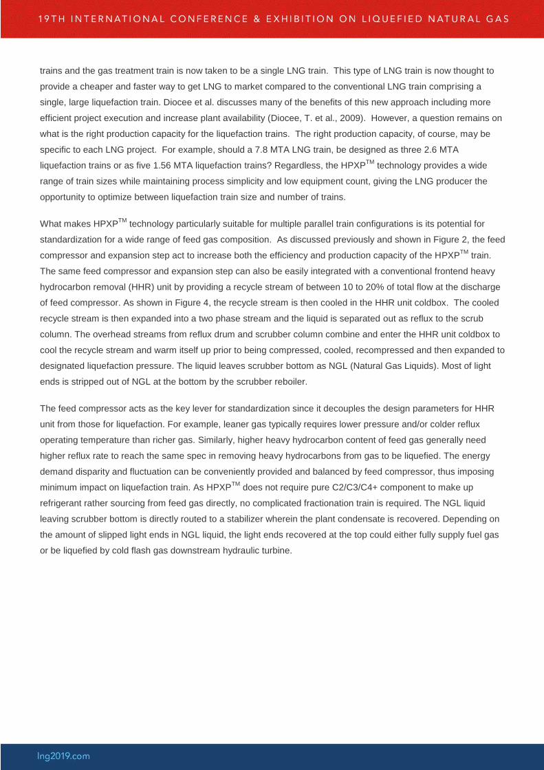
The same feed compressor and expansion step can also be easily integrated with a conventional frontend heavy
hydrocarbon removal (HHR) unit by providing a recycle stream of between 10 to 20% of total flow at the discharge
of feed compressor. As shown in Figure 4, the recycle stream is then cooled in the HHR unit coldbox. The cooled
recycle stream is then expanded into a two phase stream and the liquid is separated out as reflux to the scrub
column. The overhead streams from reflux drum and scrubber column combine and enter the HHR unit coldbox to
cool the recycle stream and warm itself up prior to being compressed, cooled, recompressed and then expanded to
designated liquefaction pressure. The liquid leaves scrubber bottom as NGL (Natural Gas Liquids). Most of light
ends is stripped out of NGL at the bottom by the scrubber reboiler.
The feed compressor acts as the key lever for standardization since it decouples the design parameters for HHR
unit from those for liquefaction. For example, leaner gas typically requires lower pressure and/or colder reflux
operating temperature than richer gas. Similarly, higher heavy hydrocarbon content of feed gas generally need
higher reflux rate to reach the same spec in removing heavy hydrocarbons from gas to be liquefied. The energy
demand disparity and fluctuation can be conveniently provided and balanced by feed compressor, thus imposing
minimum impact on liquefaction train. As HPXPTM
does not require pure C2/C3/C4+ component to make up
refrigerant rather sourcing from feed gas directly, no complicated fractionation train is required. The NGL liquid
leaving scrubber bottom is directly routed to a stabilizer wherein the plant condensate is recovered. Depending on
the amount of slipped light ends in NGL liquid, the light ends recovered at the top could either fully supply fuel gas
or be liquefied by cold flash gas downstream hydraulic turbine.
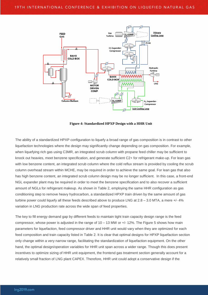
Figure 4: Standardized HPXP Design with a HHR Unit
The ability of a standardized HPXP configuration to liquefy a broad range of gas composition is in contrast to other
liquefaction technologies where the design may significantly change depending on gas composition. For example,
when liquefying rich gas using C3MR, an integrated scrub column with propane feed chiller may be sufficient to
knock out heavies, meet benzene specification, and generate sufficient C2+ for refrigerant make-up. For lean gas
with low benzene content, an integrated scrub column where the cold reflux stream is provided by cooling the scrub
column overhead stream within MCHE, may be required in order to achieve the same goal. For lean gas that also
has high benzene content, an integrated scrub column design may be no longer sufficient. In this case, a front-end
NGL expander plant may be required in order to meet the benzene specification and to also recover a sufficient
amount of NGLs for refrigerant makeup. As shown in Table 2, employing the same HHR configuration as gas
conditioning step to remove heavy hydrocarbon, a standardized HPXP train driven by the same amount of gas
turbine power could liquefy all these feeds described above to produce LNG at 2.8 – 3.0 MTA, a mere +/- 4%
variation in LNG production rate across the wide span of feed properties.
The key to fill energy demand gap by different feeds to maintain tight train capacity design range is the feed
compressor, whose power is adjusted in the range of 10 – 13 MW or +/- 12%. The Figure 5 shows how main
parameters for liquefaction, feed compressor driver and HHR unit would vary when they are optimized for each
feed composition and train capacity listed in Table 2. It is clear that optimal designs for HPXP liquefaction section
only change within a very narrow range, facilitating the standardization of liquefaction equipment. On the other
hand, the optimal design/operation variables for HHR unit span across a wider range. Though this does present
incentives to optimize sizing of HHR unit equipment, the frontend gas treatment section generally account for a
relatively small fraction of LNG plant CAPEX. Therefore, HHR unit could adopt a conservative design if the
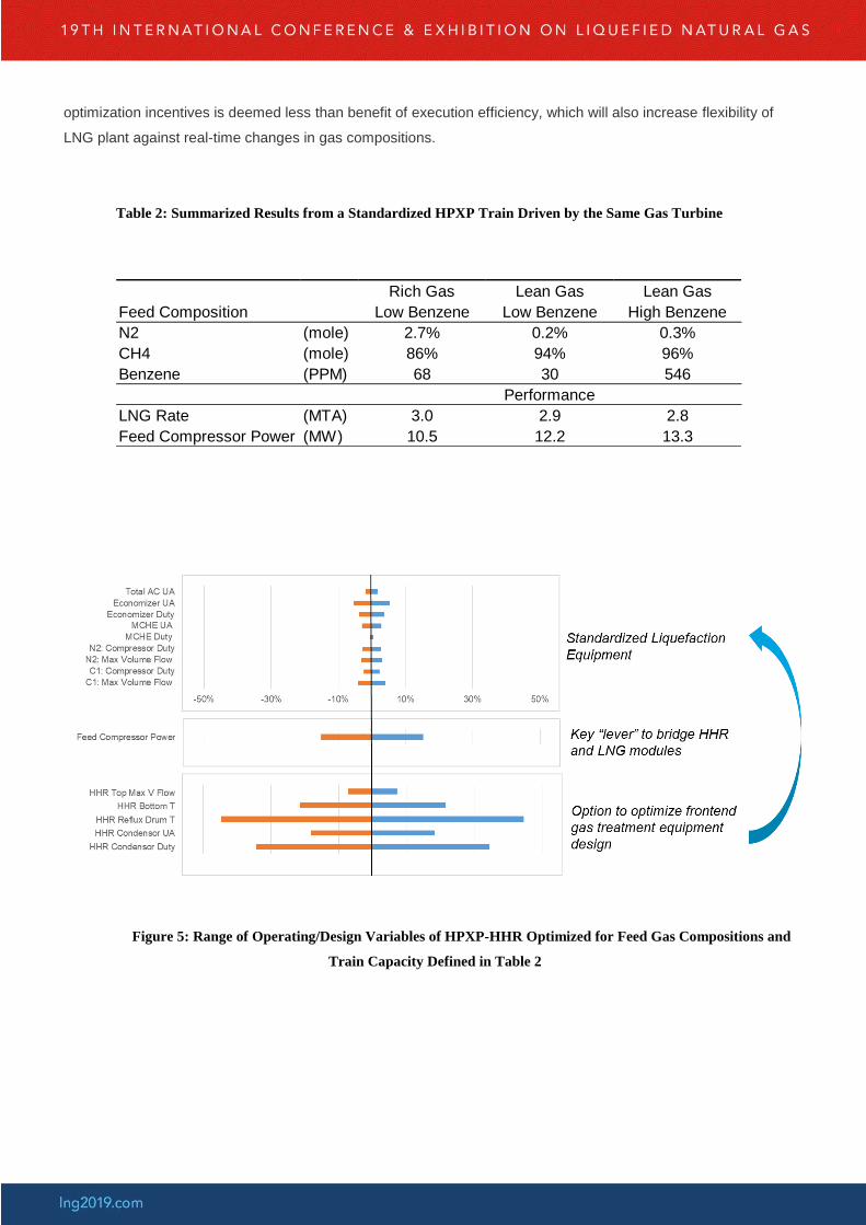
optimization incentives is deemed less than benefit of execution efficiency, which will also increase flexibility of
LNG plant against real-time changes in gas compositions.
Table 2: Summarized Results from a Standardized HPXP Train Driven by the Same Gas Turbine
Figure 5: Range of Operating/Design Variables of HPXP-HHR Optimized for Feed Gas Compositions and
Train Capacity Defined in Table 2
Rich Gas Lean Gas Lean Gas
Feed Composition Low Benzene Low Benzene High Benzene
N2 (mole) 2.7% 0.2% 0.3%
CH4 (mole) 86% 94% 96%
Benzene (PPM) 68 30 546
LNG Rate (MTA) 3.0 2.9 2.8
Feed Compressor Power (MW) 10.5 12.2 13.3
Performance
Conclusion
The ExxonMobil developed HPXPTM
liquefaction technology has an efficiency similar to that of advanced SMR
technologies while maintaining the process simplicity associated with typical expander-based technologies. The
technology’s high efficiency and wide range of train production capacity without requiring parallel equipment
provide it with a unique capability to capture application spaces which have not been traditionally considered for an
expander-based technology. The technology provides the LNG producer with more flexibility in choosing the right
liquefaction train size. In particular, its process simplicity, low equipment count, compact layout and weight over a
wide range of liquefaction train size (0.5 – 4 MTA) provide several advantages including versatility, scalability and
opportunities for modulation. These advantages were recently verified and quantified in an ExxonMobil floating
LNG study. The savings in CAPEX are significant enough to positively affect project economics beyond the amount
typically associated with choice of liquefaction process. Finally, all of these advantages along with the technology’s
standardization over a wide range of feed gas composition make HPXPTM
well suited for use in onshore and
offshore projects.
Reference
[1] Chart Energy & Chemicals, Inc. Brochure. Presented at GasTech Japan 2017.
[2] C. Dubar (BHP Billiton). Liquefaction Process, US Patent 5,768,912, 1997.
[3] K. A. Marak and B. O. Neeraas. Comparison of Expander Processes for Natural Gas Liquefaction, Statoil
Research Center Trondheim, Norway, 2010.
[4] N. Kishimoto and T. Chakrabarti (JGC). An Assessment of Liquefaction Technologies and Critical Equipment
Selection for Floating LNG Applications. FLNG London, October 2009.
[5] T. Diocee and J. M. Ellrich. Jordan Cove LNG Project Optimization through Technology and Execution Strategy.
World Gas Conference 2018.
[6] F. Pierre, Jr., S. A. Freeman, A. K. Nagavarapu, Y. Liu, C. J. Mart, 2018. The High Pressure Expander Process
(HPXP™) Technology for Floating LNG Applications. Gastech 2018 Conference.