turboexpander compressor technology for ethyleneplants
DESCRIPTION
Turboexpander compressor Technology For EthylenePlantsTRANSCRIPT
GE Oil & Gas
GE imagination at work
Turboexpander-compressor technology for ethylene plants By Kara ByrnE, GaBriElE MariOTTi / GE Oil & Gas
1
GE Oil & Gas
This paper was prepared for presentation at the alChE 2010 spring national Meeting, held in san antonio, Usa, March 21-25, 2010
ForewordThe importance of turboexpanders has increased significantly over the past few decades since the first application of a turboexpander in the oil and gas industry by the founder of rotoflow, Dr. Judson swearingen. Typically, turboexpanders were used to replace a Joule-Thompson (JT) valve in order to increase the overall efficiency of air separation plants. Driven by increased competition in the oil and gas market , it is increasingly common to find a turboexpander as a key component for overall production in a hydrocarbon gas separation plant. This is especially important for designing a more efficient and competitive ethylene plant.
While the turboexpander alone can easily reach isentropic efficiencies of up to 90%, when it is directly coupled to a compressor the interaction of the two machines must be taken into account. The turboexpander efficiency is limited by the compressor (and vice versa) and, therefore, cannot be optimized beyond the mechanical limitations of each machine.
This paper, after a brief discussion of current technologies and the characteristics of GE Oil & Gas turboexpanders, will focus on some typical turboexpander compressor selections showing the interaction between the selection of the turboexpander and re-compressor.
Turboexpander-compressor technology for ethylene plants By Kara ByrnE, GaBriElE MariOTTi / GE Oil & Gas
AbstractToday’s ethylene plants incorporate turboexpander systems to optimize cryogenic recovery and reduce energy demand. The molecular weight and flow rate of the residue gas depends directly on the selected upstream feedstock gas composition, conversion, and feed rates. Recently, a variety of ethylene units have generated residue gas volumetric flow ranges around 100-200%. Hence, the turboexpander system is designed and manufactured accordingly.
As we know, the typical naphtha cracker produces a methane-rich residue gas (bulk hydrogen is recovered, treated, and delivered as a high pressure co-product). Conversely, the typical ethane or E/P cracker produces a very high hydrogen content residue gas. Current designs and revamps require a wider range of feedstocks and, therefore, a correspondingly wide range of residue gas composition and quantity.
In order to meet these demands, the turboexpander solution must be flexible. As an overview, we will discuss the typical performance of one- and two-stage turboexpander solutions for the expansion and re-compression of the residue gas. Key mechanical design recommendations (e.g., magnetic bearings, variable nozzles, multistage control, high head wheels) will be outlined. Based on demand from the different feedstocks and the industry requirements for feedstock flexibility, we will then discuss the technology and mechanical solutions. This presentation will also include related design improvements that have been successfully utilized in other turboexpander applications.
2
GE Oil & Gas
Turboexpander historyThe turboexpander is a reaction type radial turbine originally developed to replace the Joule-Thompson (JT) valve in air separation plants.
The French engineer, George Claude, utilized the first radial turbine for air liquefaction in the early 1900s. German engineers, including Dr. Carl von linde, further developed and improved the turbines for many other applications, such as refrigeration and jet propulsion engines.
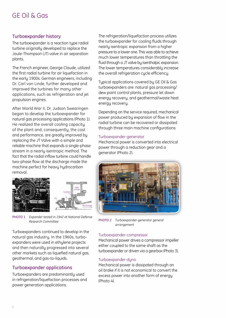
after World War ii, Dr. Judson swearingen began to develop the turboexpander for natural gas processing applications (Photo 1). He realized the overall cooling capacity of the plant and, consequently, the cost and performance, are greatly improved by replacing the JT Valve with a simple and reliable machine that expands a single-phase stream in a nearly isentropic method. The fact that the radial inflow turbine could handle two-phase flow at the discharge made the machine perfect for heavy hydrocarbon removal.
PhoTo 1 Expander tested in 1942 at National Defense Research Committee
Turboexpanders continued to develop in the natural gas industry. in the 1960s, turbo-expanders were used in ethylene projects and then naturally progressed into several other markets such as liquefied natural gas, geothermal, and gas-to-liquids.
Turboexpander applicationsTurboexpanders are predominantly used in refrigeration/liquefaction processes and power generation applications.
The refrigeration/liquefaction process utilizes the turboexpander for cooling fluids through nearly isentropic expansion from a higher pressure to a lower one. This was able to achieve much lower temperatures than throttling the fluid through a JT valve by isenthalpic expansion. The lower temperatures considerably increase the overall refrigeration cycle efficiency.
Typical applications covered by GE Oil & Gas turboexpanders are: natural gas processing/dew point control plants, pressure let down energy recovery, and geothermal/waste heat energy recovery.
Depending on the service required, mechanical power produced by expansion of flow in the radial turbine can be recovered or dissipated through three main machine configurations:
Turboexpander-generatorMechanical power is converted into electrical power through a reduction gear and a generator (Photo 2).
PhoTo 2 Turboexpander-generator general arrangement
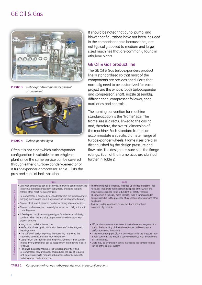
Turboexpander-compressorMechanical power drives a compressor impeller either coupled to the same shaft as the turboexpander or driven via a gearbox (Photo 3).
Turboexpander-dynoMechanical power is dissipated through an oil brake if it is not economical to convert the excess power into another form of energy (Photo 4).
oil A
nozzles
inletvolute
discharge
3
GE Oil & Gas
PhoTo 3 Turboexpander-compressor general arrangement
PhoTo 4 Turboexpander-dyno
Often it is not clear which turboexpander configuration is suitable for an ethylene plant since the same service can be covered through either a turboexpander-generator or a turboexpander-compressor. Table 1 lists the pros and cons of both solutions.
Pros Cons
Turb
oexp
ande
r-ge
nera
tor
• Very high efficiencies can be achieved. The wheel can be optimized to achieve the best aerodynamics by freely changing the rpm without other machinery constraints
• Re-compressor is designed independently from the turboexpander, merging more stages into a single machine with higher efficiency
• Simpler plant layout: reduced number of piping interconnections
• Simpler machine control can easily be set-up for a fully automatic control system
• A fixed speed machine can typically perform better in off-design condition when the enthalpy drop is maintained constant with process controls
• The machine has a tendency to speed up in case of electric load rejection. This limits the maximum tip speed of the wheel and tripping devices need to be redundant for safety reasons
• The machine is typically more complex than a turboexpander-compressor due to the presence of a gearbox, generator, and other auxiliaries
• Cost per unit is higher and oil free solutions are not yet economically feasible
Turb
oexp
ande
r-co
mpr
esso
r
• Very robust and simple machine• Perfect for oil free applications with the use of active magnetic
bearings (aMB)• The stiff shaft design improves the operating range and the
capability to withstand very high imbalances• Labyrinth, or similar, seals and the pressurized auxiliaries system
makes it very difficult for gas to escape from the machine in case of failure
• For a well-balanced machine, the turboexpander flow and re-compressor flow are linked. This reduces the size of required anti-surge systems to manage imbalances in flow between the turboexpander and compressor
• Efficiencies are sometimes lower than turboexpander-generator due to the balancing of the turboexpander and compressor performance and limitations
• If the plant throughput (flow) is decreased while the pressure ratio is kept constant, the machine speed will reduce with a significant loss in efficiency
• Units may be arranged in series, increasing the complexity and tuning of the control system
it should be noted that dyno, pump, and blower configurations have not been included in the comparison table because they are not typically applied to medium and large sized machines that are commonly found in ethylene plants.
GE oil & Gas product lineThe GE Oil & Gas turboexpanders product line is standardized so that most of the components are pre-designed. Parts that normally need to be customized for each project are the wheels (both turboexpander and compressor), shaft, nozzle assembly, diffuser cone, compressor follower, gear, auxiliaries and controls.
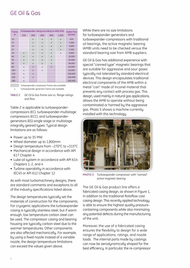
The naming convention for machine standardization is the “frame” size. The frame size is directly linked to the casing and, therefore, the overall dimension of the machine. Each standard frame can accommodate a specific diameter range of turboexpander wheels. Frame sizes are also distinguished by the design pressure and flow rate. The design pressure sets the flange ratings. Each of the frame sizes are clarified further in Table 2.
TAblE 1 Comparison of various turboexpander machinery configurations
4
GE Oil & Gas
Frame #
Turboexpander rating according to ANSI (PSI) outlet Flow (ACMh)150 300 600 900 1,500
10 x x x x 450
15 x x x x 1,000
20 x x x x 4,000
25 x x x x 5,500
30 x x x x x 9,000
40 x x x x 16,000
50 x x x x 25,000
60 x x x x 36,000
80 x x x x 45,000
100 x x x 65,000
130 x x 100,000
160 x x 160,000
180 x 200,000
Turboexpander compressor frame size available
x Turboexpander generator frame size available
TAblE 2 GE Oil & Gas frame size vs. flange ratings and flow
Table-2 is applicable to turboexpander-compressors (EC), turboexpander-multistage compressors (ECC), and turboexpander-generators (EG) single stage or multistage integrally geared types. Typical design limitations are as follows:
• Power up to 35 MW• Wheel diameter up to 1,800mm• Design temperature from –270°C to +315°C• Mechanical design in accordance with API 617 Chapter 4• Lube oil system in accordance with API 614 Chapters 1, 2, and 4• Turbine operability in accordance with iEC45 or aPi 612 Chapter 12
as with most turbomachinery designs, there are standard comments and exceptions to all of the industry specifications listed above.
The design temperatures typically set the materials of construction for the components. For cryogenic applications the turboexpander casing is typically stainless steel, but if warm enough, low temperature carbon steel can be used. The compressor casing and bearing housing are typically carbon steel due to the warmer temperatures. Other components are also affected mechanically. For example, by using a fixed nozzle instead of a variable nozzle, the design temperature limitations can exceed the values given above.
While there are no size limitations for turboexpander-generators and turboexpander-compressors with traditional oil bearings, the active magnetic bearing (aMB) units need to be checked versus the standard bearing size from aMB suppliers.
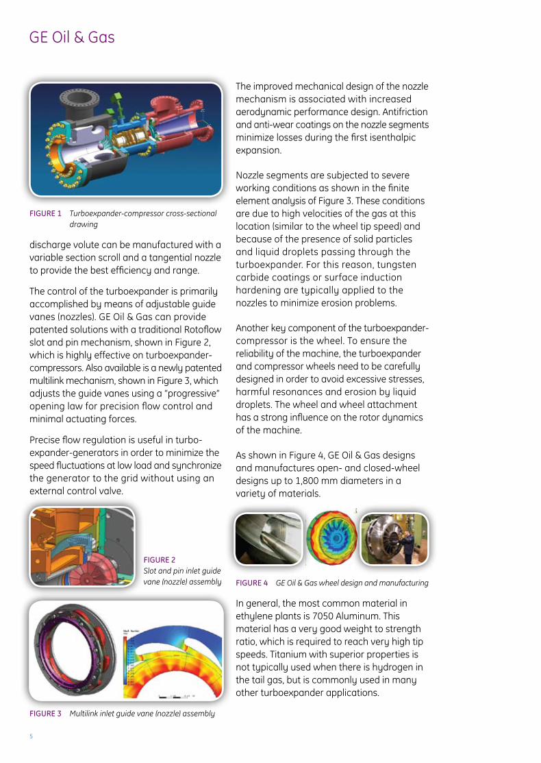
GE Oil & Gas has additional experience with special “canned type” magnetic bearings that are suitable for aggressive and sour gases typically not tolerated by standard electrical devices. This design encapsulates traditional electrical components of the aMB within a metal “can” made of inconel material that prevents any contact with process gas. This design, used mainly in natural gas applications, allows the aMB to operate without being contaminated or harmed by the aggressive gas. Photo 5 shows a machine currently installed with this technology.
PhoTo 5 Turboexpander-compressor with “canned” active magnetic bearing
The GE Oil & Gas product line offers a fabricated casing design, as shown in Figure 1, in addition to the traditional rotoflow cast casing design. This recently applied technology is able to ensure the highest quality pressure- containing components while also minimizing any potential defects during the manufacturing of the unit.
Moreover, the use of a fabricated casing ensures the flexibility to design for a wide range of applications, ratings, and nozzle loads. The internal parts made by castings can now be aerodynamically shaped for the best efficiency. in particular, the re-compressor
5
GE Oil & Gas
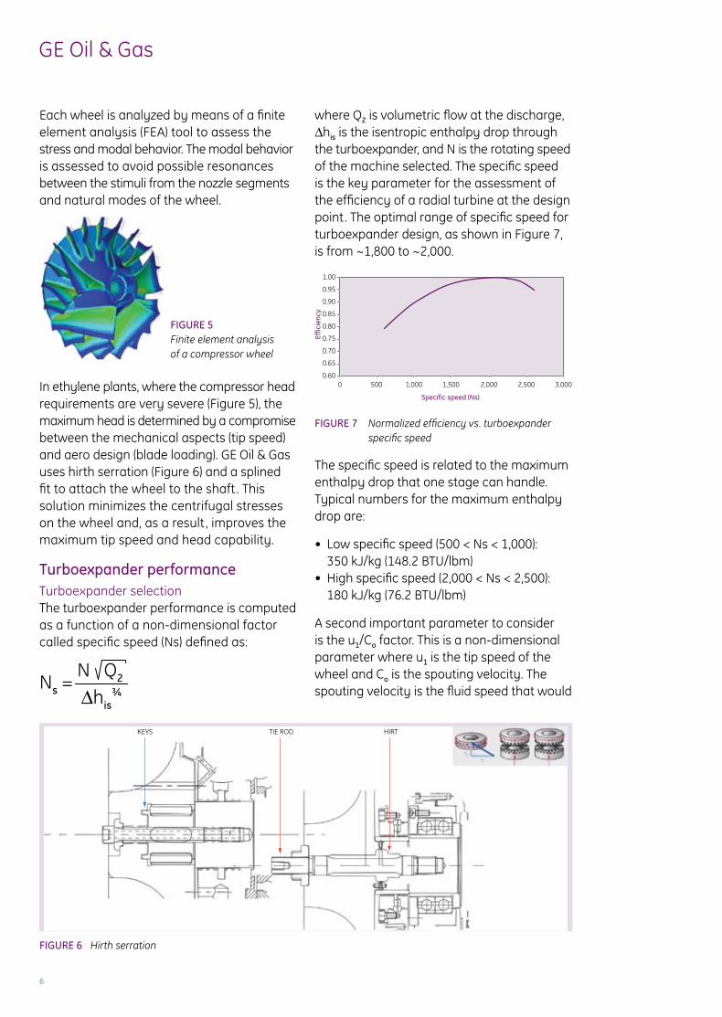
FIGURE 1 Turboexpander-compressor cross-sectional drawing
discharge volute can be manufactured with a variable section scroll and a tangential nozzle to provide the best efficiency and range.
The control of the turboexpander is primarily accomplished by means of adjustable guide vanes (nozzles). GE Oil & Gas can provide patented solutions with a traditional rotoflow slot and pin mechanism, shown in Figure 2, which is highly effective on turboexpander-compressors. also available is a newly patented multilink mechanism, shown in Figure 3, which adjusts the guide vanes using a “progressive” opening law for precision flow control and minimal actuating forces.
Precise flow regulation is useful in turbo-expander-generators in order to minimize the speed fluctuations at low load and synchronize the generator to the grid without using an external control valve.
FIGURE 2 Slot and pin inlet guide vane (nozzle) assembly
FIGURE 3 Multilink inlet guide vane (nozzle) assembly
The improved mechanical design of the nozzle mechanism is associated with increased aerodynamic performance design. antifriction and anti-wear coatings on the nozzle segments minimize losses during the first isenthalpic expansion.
nozzle segments are subjected to severe working conditions as shown in the finite element analysis of Figure 3. These conditions are due to high velocities of the gas at this location (similar to the wheel tip speed) and because of the presence of solid particles and liquid droplets passing through the turboexpander. For this reason, tungsten carbide coatings or surface induction hardening are typically applied to the nozzles to minimize erosion problems.
another key component of the turboexpander-compressor is the wheel. To ensure the reliability of the machine, the turboexpander and compressor wheels need to be carefully designed in order to avoid excessive stresses, harmful resonances and erosion by liquid droplets. The wheel and wheel attachment has a strong influence on the rotor dynamics of the machine.
as shown in Figure 4, GE Oil & Gas designs and manufactures open- and closed-wheel designs up to 1,800 mm diameters in a variety of materials.
FIGURE 4 GE Oil & Gas wheel design and manufacturing
in general, the most common material in ethylene plants is 7050 Aluminum. This material has a very good weight to strength ratio, which is required to reach very high tip speeds. Titanium with superior properties is not typically used when there is hydrogen in the tail gas, but is commonly used in many other turboexpander applications.
ZC
XCYC
6
GE Oil & Gas
Each wheel is analyzed by means of a finite element analysis (FEa) tool to assess the stress and modal behavior. The modal behavior is assessed to avoid possible resonances between the stimuli from the nozzle segments and natural modes of the wheel.
FIGURE 5 Finite element analysis of a compressor wheel
in ethylene plants, where the compressor head requirements are very severe (Figure 5), the maximum head is determined by a compromise between the mechanical aspects (tip speed) and aero design (blade loading). GE Oil & Gas uses hirth serration (Figure 6) and a splined fit to attach the wheel to the shaft . This solution minimizes the centrifugal stresses on the wheel and, as a result , improves the maximum tip speed and head capability.
Turboexpander performanceTurboexpander selectionThe turboexpander performance is computed as a function of a non-dimensional factor called specific speed (ns) defined as:
FIGURE 6 Hirth serration
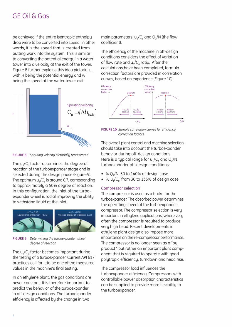
where Q2 is volumetric flow at the discharge, Δhis is the isentropic enthalpy drop through the turboexpander, and n is the rotating speed of the machine selected. The specific speed is the key parameter for the assessment of the efficiency of a radial turbine at the design point. The optimal range of specific speed for turboexpander design, as shown in Figure 7, is from ~1,800 to ~2,000.
FIGURE 7 Normalized efficiency vs. turboexpander specific speed
The specific speed is related to the maximum enthalpy drop that one stage can handle. Typical numbers for the maximum enthalpy drop are:
• Low specific speed (500 < Ns < 1,000): 350 kJ/kg (148.2 BTU/lbm)• High specific speed (2,000 < Ns < 2,500): 180 kJ/kg (76.2 BTU/lbm)
a second important parameter to consider is the u1/Co factor. This is a non-dimensional parameter where u1 is the tip speed of the wheel and Co is the spouting velocity. The spouting velocity is the fluid speed that would
TIE RODKEYS HIRT
ns = n Q2
Δhis¾
1.00
0.95
0.90
0.85
0.80
0.75
0.70
0.65
0.600 500 1,000 1,500 2,000 2,500 3,000
Effic
ienc
y
Specific speed (Ns)
7
GE Oil & Gas
be achieved if the entire isentropic enthalpy drop were to be converted into speed. in other words, it is the speed that is created from putting work into the system. This is similar to converting the potential energy in a water tower into a velocity at the exit of the tower. Figure 8 further explains this idea pictorially, with H being the potential energy and w being the speed at the water tower exit.
FIGURE 8 Spouting velocity pictorially represented
The u1/Co factor determines the degree of reaction of the turboexpander stage and is selected during the design phase (Figure-9). The optimum u1/Co is around 0.7, corresponding to approximately a 50% degree of reaction. in this configuration, the inlet of the turbo-expander wheel is radial, improving the ability to withstand liquid at the inlet.
FIGURE 9 Determining the turboexpander wheel degree of reaction
The u1/Co factor becomes important during the testing of a turboexpander. Current API 617 practices call for it to be one of the measured values in the machine’s final testing.
in an ethylene plant, the gas conditions are never constant. it is therefore important to predict the behavior of the turboexpander in off-design conditions. The turboexpander efficiency is affected by the change in two
main parameters: u1/Co and Q2/n (the flow coefficient).
The efficiency of the machine in off-design conditions considers the effect of variation of flow rate and u1/Co ratio. after the calculations have been completed, formula correction factors are provided in correlation curves, based on experience (Figure 10).
FIGURE 10 Sample correlation curves for efficiency correction factors
The overall plant control and machine selection should take into account the turboexpander behavior during off-design conditions. Here is a typical range for u1/Co and Q2/n turboexpander off-design conditions:
• % Q2/n: 30 to 140% of design case• % u1/Co: from 30 to 135% of design case
Compressor selectionThe compressor is used as a brake for the turboexpander. The absorbed power determines the operating speed of the turboexpander-compressor. The compressor selection is very important in ethylene applications, where very often the compressor is required to produce very high head. recent developments in ethylene plant design also impose more importance on the re-compressor performance. The compressor is no longer seen as a “by product,” but rather an important plant comp- onent that is required to operate with good polytropic efficiency, turndown and head rise.
The compressor load influences the turboexpander efficiency. Compressors with controllable power absorption characteristics can be supplied to provide more flexibility to the turboexpander.
H
W
Co = Δhts,is
spouting velocity:
u1/C0 = 0.63Low degree of reaction (~0.35)
u1/C0 = 0.68Average degree of reaction (~0.55)
Efficiencycorrectionfactor
EfficiencycorrectionfactorDESIGN
nozzle opening
nozzleclosing
DESIGN
u1/c0 Q/N
nozzle opening
nozzleclosing
8
GE Oil & Gas
The compressor selection is made using three main parameters:
• Flow coefficient:
• Compressor peripheral Mach number:
• Flow coefficient:
where Q1 is the volumetric flow at the inlet, D2 is the impeller diameter and u2 is the wheel peripheral speed.
The capability for a given wheel to produce power depends on both τ and u2 squared and the mass flow rate that is handled by the compressor wheel.
The work coefficient is limited by the aerodynamic design of the wheel and the peripheral speed affects the static stress on the impeller. in ethylene applications, the Mach number is normally not an issue because of the low molecular weight gas.
Typical numbers for the maximum enthalpy change on the compressor wheel are as follows:
• Low flow coefficient (0.025 < φ < 0.100): 150 kJ/kg (63.5 BTU/lbm)• High flow coefficient (0.180 < φ < 0.280): 120 kJ/kg (50.8 BTU/lbm)
a well-balanced turboexpander and compressor wheel depends on the process design. The turboexpander wheel power (including mechanical losses) should be the same as the compressor absorbed power.
it should be noted that the capability for the compressor to act as a load for the turboexpander does not depend on the polytropic efficiency. For this reason, an
optional hot bypass around the compressors can be used to artificially increase the absorbed power, also reducing the turboexpander speed. as a consequence, the efficiency of the compressor will drop because of the “internal” recirculation.
Turboexpander and compressor interactionas seen earlier, the specific speed (ns) is one of the main parameters to determine the efficiency of the expander. The efficiency vs. ns curve has a flat peak portion ranging from ~1,800 to ~2,000 (Graph 2).
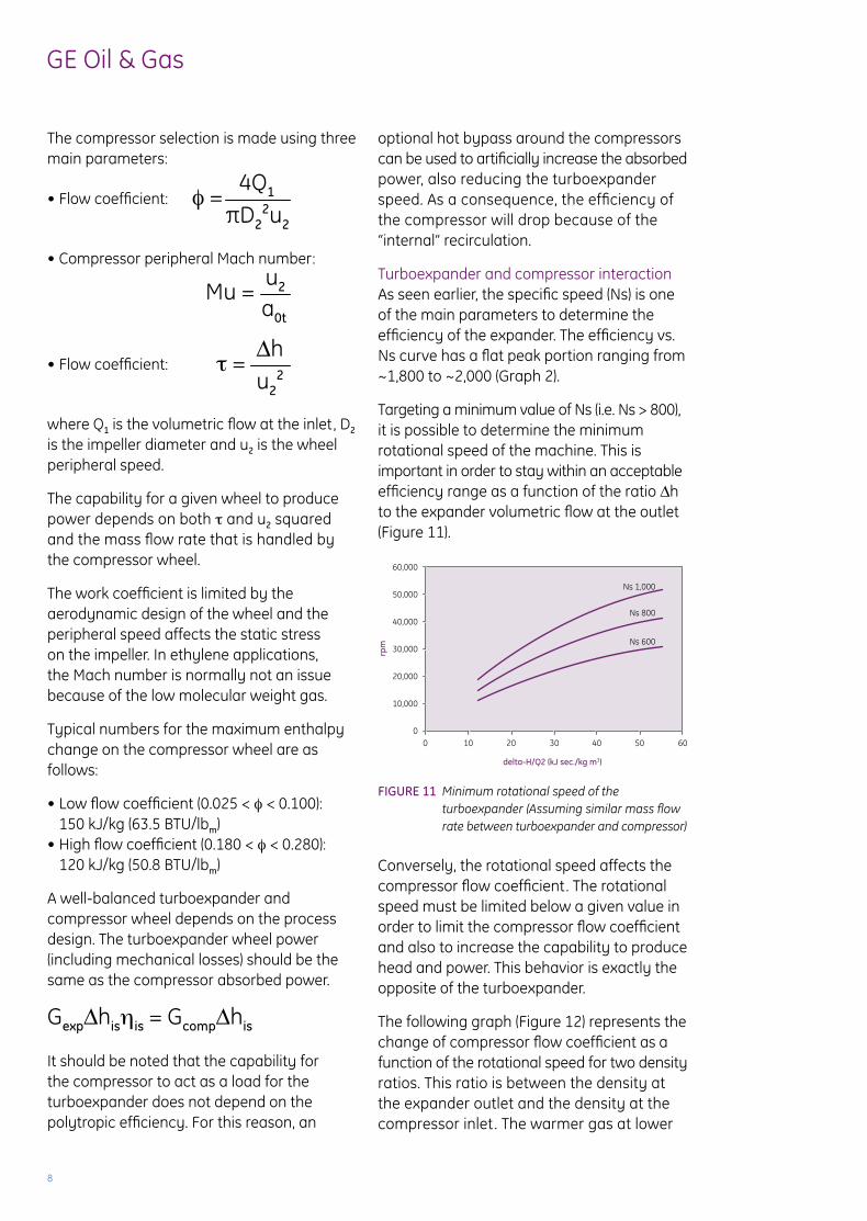
Targeting a minimum value of ns (i.e. ns > 800), it is possible to determine the minimum rotational speed of the machine. This is important in order to stay within an acceptable efficiency range as a function of the ratio Δh to the expander volumetric flow at the outlet (Figure 11).
FIGURE 11 Minimum rotational speed of the turboexpander (Assuming similar mass flow rate between turboexpander and compressor)
Conversely, the rotational speed affects the compressor flow coefficient. The rotational speed must be limited below a given value in order to limit the compressor flow coefficient and also to increase the capability to produce head and power. This behavior is exactly the opposite of the turboexpander.
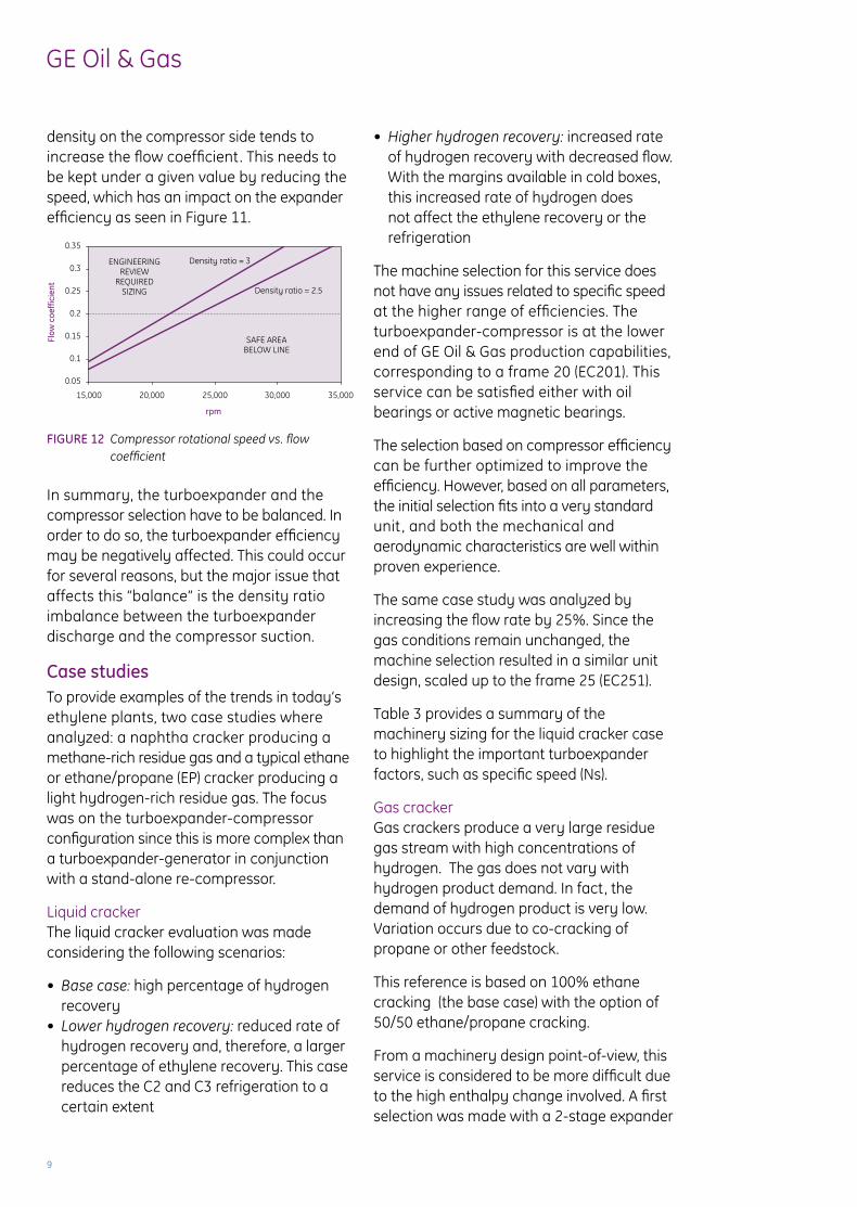
The following graph (Figure 12) represents the change of compressor flow coefficient as a function of the rotational speed for two density ratios. This ratio is between the density at the expander outlet and the density at the compressor inlet . The warmer gas at lower
φ = 4Q1
πD22u2
τ = Δhu2
2
Mu = u2
a0t
GexpΔhisηis = GcompΔhis
60,000
50,000
40,000
30,000
20,000
10,000
00 10 20 30 40 50 60
Ns 1,000
Ns 800
Ns 600
delta-H/Q2 (kJ sec./kg m3)
rpm
9
GE Oil & Gas
density on the compressor side tends to increase the flow coefficient. This needs to be kept under a given value by reducing the speed, which has an impact on the expander efficiency as seen in Figure 11.
FIGURE 12 Compressor rotational speed vs. flow coefficient
in summary, the turboexpander and the compressor selection have to be balanced. in order to do so, the turboexpander efficiency may be negatively affected. This could occur for several reasons, but the major issue that affects this “balance” is the density ratio imbalance between the turboexpander discharge and the compressor suction.
Case studiesTo provide examples of the trends in today’s ethylene plants, two case studies where analyzed: a naphtha cracker producing a methane-rich residue gas and a typical ethane or ethane/propane (EP) cracker producing a light hydrogen-rich residue gas. The focus was on the turboexpander-compressor configuration since this is more complex than a turboexpander-generator in conjunction with a stand-alone re-compressor.
liquid cracker The liquid cracker evaluation was made considering the following scenarios:
• Base case: high percentage of hydrogen recovery• Lower hydrogen recovery: reduced rate of hydrogen recovery and, therefore, a larger percentage of ethylene recovery. This case reduces the C2 and C3 refrigeration to a certain extent
• Higher hydrogen recovery: increased rate of hydrogen recovery with decreased flow. With the margins available in cold boxes, this increased rate of hydrogen does not affect the ethylene recovery or the refrigeration
The machine selection for this service does not have any issues related to specific speed at the higher range of efficiencies. The turboexpander-compressor is at the lower end of GE Oil & Gas production capabilities, corresponding to a frame 20 (EC201). This service can be satisfied either with oil bearings or active magnetic bearings.
The selection based on compressor efficiency can be further optimized to improve the efficiency. However, based on all parameters, the initial selection fits into a very standard unit , and both the mechanical and aerodynamic characteristics are well within proven experience.
The same case study was analyzed by increasing the flow rate by 25%. since the gas conditions remain unchanged, the machine selection resulted in a similar unit design, scaled up to the frame 25 (EC251).
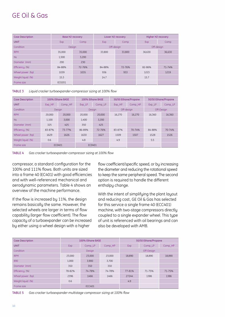
Table 3 provides a summary of the machinery sizing for the liquid cracker case to highlight the important turboexpander factors, such as specific speed (ns).
Gas crackerGas crackers produce a very large residue gas stream with high concentrations of hydrogen. The gas does not vary with hydrogen product demand. in fact, the demand of hydrogen product is very low. Variation occurs due to co-cracking of propane or other feedstock.
This reference is based on 100% ethane cracking (the base case) with the option of 50/50 ethane/propane cracking.
From a machinery design point-of-view, this service is considered to be more difficult due to the high enthalpy change involved. a first selection was made with a 2-stage expander
0.35
0.3
0.25
0.2
0.15
0.1
0.05
15,000 20,000 25,000 30,000 35,000
Flow
coe
ffic
ient
rpm
ENGINEERINGREVIEW
REQUIREDSIZING
SAFE AREABELOW LINE
Density ratio = 3
Density ratio = 2.5
10
GE Oil & Gas
Case Description base h2 recovery lower h2 recovery higher h2 recovery
UNIT Exp Comp Exp Comp Exp Comp
Condition Design Off-design Off-design
rPM 35,000 35,000 33,800 33,800 36,630 36,630
ns 1,500 3,200
Diameter (mm) 200 230
Efficiency (%) 84-88% 72-76% 84-88% 72-76% 82-86% 71-74%
Wheel power (hp) 1039 1035 936 933 1223 1219
Weight liquid (%) 15.3 14.7 15.7
Frame size EC0201
Case Description 100% Ethane bASE 100% Ethane bASE 50/50 Ethane/Propane 50/50 Ethane/Propane
UNIT Exp_HP Comp_HP Exp_lP Comp_lP Exp_HP Comp_HP Exp_lP Comp_lP
Condition Design Design Off-design Off-Design
rPM 20,000 20,000 20,000 20,000 16,270 16,270 16,360 16,360
ns 1,100 3,000 1,400 3,200
Diameter (mm) 325 425 350 425
Efficiency (%) 83-87% 73-77% 86-89% 72-76% 83-87% 70-74% 84-88% 70-74%
Wheel power (hp) 1629 1626 1630 1627 1509 1507 1528 1526
Weight liquid (%) 0.6 4.8 4.9 5.5
Frame size EC0401 EC0401
compressor, a standard configuration for the 100% and 111% flows. Both units are sized into a frame 40 (EC401) with good efficiencies and with well-referenced mechanical and aerodynamic parameters. Table 4 shows an overview of the machine performance.
if the flow is increased by 11%, the design remains basically the same. However, the selected wheels are larger in terms of flow capability (larger flow coefficient). The flow capacity of a turboexpander can be increased by either using a wheel design with a higher
flow coefficient/specific speed, or by increasing the diameter and reducing the rotational speed to keep the same peripheral speed. The second option is required to handle the different enthalpy change.
With the intent of simplifying the plant layout and reducing cost, GE Oil & Gas has selected for this service a single frame 40 (ECC401) machine, with two-stage compressors directly coupled to a single expander wheel. This type of unit is referenced with oil bearings and can also be developed with aMB.
TAblE 3 Liquid cracker turboexpander-compressor sizing at 100% flow
TAblE 4 Gas cracker turboexpander-compressor sizing at 100% flow
TAblE 5 Gas cracker turboexpander-multistage compressor sizing at 100% flow
Case Description 100% Ethane bASE 50/50 Ethane/Propane
UNIT Exp Comp_lP Comp_HP Exp Comp_lP Comp_HP
Condition Design Off-Design
rPM 23,000 23,000 23,000 18,890 18,890 18,890
890 1,000 3,900 3,700
Diameter (mm) 350 350 350
Efficiency (%) 78-82% 74-78% 74-78% 77-81% 71-75% 71-75%
Wheel power (hp) 2396 1466 1466 27244 1386 1386
Weight liquid (%) 0.6 4.9
Frame size ECC401
11
GE Oil & Gas
Due to the very high enthalpy drop across the expander stage, the efficiency is highly penalized with respect to the traditional design at nearly the same specific speed.
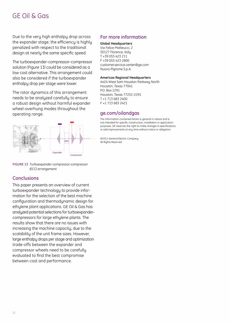
The turboexpander-compressor-compressor solution (Figure 13) could be considered as a low cost alternative. This arrangement could also be considered if the turboexpander enthalpy drop per stage were lower.
The rotor dynamics of this arrangement needs to be analyzed carefully to ensure a robust design without harmful expander wheel-overhung modes throughout the operating range.
FIGURE 13 Turboexpander-compressor-compressor (ECC) arrangement
ConclusionsThis paper presents an overview of current turboexpander technology to provide infor- mation for the selection of the best machine configuration and thermodynamic design for ethylene plant applications. GE Oil & Gas has analyzed potential selections for turboexpander-compressors for large ethylene plants. The results show that there are no issues with increasing the machine capacity, due to the scalability of the unit frame sizes. However, large enthalpy drops per stage and optimization trade-offs between the expander and compressor wheels need to be carefully evaluated to find the best compromise between cost and performance.
For more informationGlobal HeadquartersVia Felice Matteucci, 250127 Florence, ItalyT +39 055 423 211F +39 055 423 [email protected] Pignone s.p.a.
Americas Regional Headquarters4424 West sam Houston Parkway northHouston, Texas 77041P.O. Box 2291Houston, Texas 77252-2291T +1 713 683 2400F +1 713 683 2421
ge.com/oilandgasThe information contained herein is general in nature and is not intended for specific construction, installation or application purposes. GE reserves the right to make changes in specifications or add improvements at any time without notice or obligation.
©2011 General Electric Company all rights reserved
ExpanderCompressor
BRG