economic assessment of a hybrid turboexpander-fuel cell...
TRANSCRIPT
Turk J Elec Eng & Comp Sci
(2016) 24: 733 – 745
c⃝ TUBITAK
doi:10.3906/elk-1303-7
Turkish Journal of Electrical Engineering & Computer Sciences
http :// journa l s . tub i tak .gov . t r/e lektr ik/
Research Article
Economic assessment of a hybrid turboexpander-fuel cell gas energy extraction
plant
Ahmad DARABI1,∗, Ahmad SHARIATI1, Reza GHANAEI1, Ali SOLEIMANI1,21Faculty of Electrical Engineering, Shahrood University of Technology, Shahrood, Iran
2Research Center of Marine Propulsions, Shahrood University of Technology, Iran
Received: 02.03.2013 • Accepted/Published Online: 02.08.2013 • Final Version: 23.03.2016
Abstract: In this paper, a hybrid turboexpander-fuel cell (TE-FC) is investigated for extraction of electrical energy
from high pressure gas in which the fuel cells are used for preheating the gas. Combination of expanders and fuel cells
will reduce the fuel consumption and greenhouse gas emission. This study reveals that there are some circumstances in
which the use of fuel cells in conjunction with a turboexpander is not recommended from an economic point of view.
This paper seeks the region in which utilization of fuel cells along with a turboexpander presents maximum economic
profit. Using the strategy provided in this paper one can decide whether to invest in the hybrid fuel cells-turboexpander
or individually planned turboexpander with a conventional gas fired preheating system. Almost all effective parameters
are taken into account and this can be considered a superiority of the present paper.
Key words: Clean energy resources, gas energy extraction system, turboexpander, fuel cell
1. Introduction
The worldwide energy crisis and increasing demand for energy necessitate optimizing consumption. In this
regard, many countries are compiling some programs for the future years in order to supply securely their
energy requirements. On the other hand, the large amounts of greenhouse gas emissions are a global concern
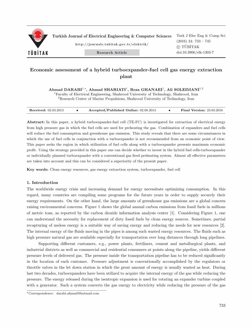
raising environmental concerns. Figure 1 shows the global annual carbon emissions from fossil fuels in millions
of metric tons, as reported by the carbon dioxide information analysis center [1]. Considering Figure 1, one
can understand the necessity for replacement of dirty fossil fuels by clean energy sources. Sometimes, partial
recapturing of useless energy is a suitable way of saving energy and reducing the needs for new resources [2].
The internal energy of the fluids moving in the pipes is among such wasted energy resources. The fluids such as
high pressure natural gas are available especially for transportation over long distances through long pipelines.
Supporting different customers, e.g., power plants, fertilizers, cement and metallurgical plants, and
industrial districts as well as commercial and residential consumers at points along the pipeline, yields different
pressure levels of delivered gas. The pressure inside the transportation pipeline has to be reduced significantly
in the location of each customer. Pressure adjustment is conventionally accomplished by the regulators or
throttle valves in the let down station in which the great amount of energy is usually wasted as heat. During
last two decades, turboexpanders have been utilized to acquire the internal energy of the gas while reducing the
pressure. The energy released during the isentropic expansion is used for rotating an expander turbine coupled
with a generator. Such a system converts the gas energy to electricity while reducing the pressure of the gas
∗Correspondence: darabi [email protected]
733
DARABI et al./Turk J Elec Eng & Comp Sci
to a value specified properly for each customer. This system produces electrical energy without any NOx and
SOx emissions, meeting the environmental criteria.
0
2.000
4.000
6.000
8.000
10.000
12.000
17
51
17
60
17
69
17
78
17
87
17
96
18
05
18
14
18
23
18
32
18
41
18
50
18
59
18
68
18
77
18
86
18
95
19
04
19
13
19
22
19
31
19
40
19
49
19
58
19
67
19
76
19
85
19
94
20
03
20
12
Mil
ion
to
nes o
f carb
on
Figure 1. Global carbon dioxide emission from fossil fuel burning (www.cdiac.ornl.gov).
It is a few decades since turboexpanders were installed across the gas pipe lines and they are operating
now in some countries like Italy, Russia, Germany, Denmark, the USA, and the UK. However, unavailability
of the complicated technology and installation costs are the main reasons for less development and use of
turboexpanders in some countries [1]. Turboexpanders were employed in steam compressors in 1978 in Denmark
and then used in other applications gradually (www.cdiac.ornl.gov). A gas turboexpander is employed in
Belgium’s public distribution network; it was commissioned by Electrabel, Belgium’s main electricity generator,
the largest distributor of gas and electricity in the country. It uses a turboexpander designed to reduce natural
gas pressure within 8–14 to about 1.7 bars in preparation for delivery to the final distribution network. The
potential energy of the gas drives a 2.6 MW alternator [3]. Furthermore, a turboexpander is installed in
a power plant at ERG’s oil refinery in Priolo Gargallo, near Siracusa, Sicily in Italy. The turboexpander
was manufactured at GE Energy’s facilities in Belfort, France, and was shipped to the project site in late
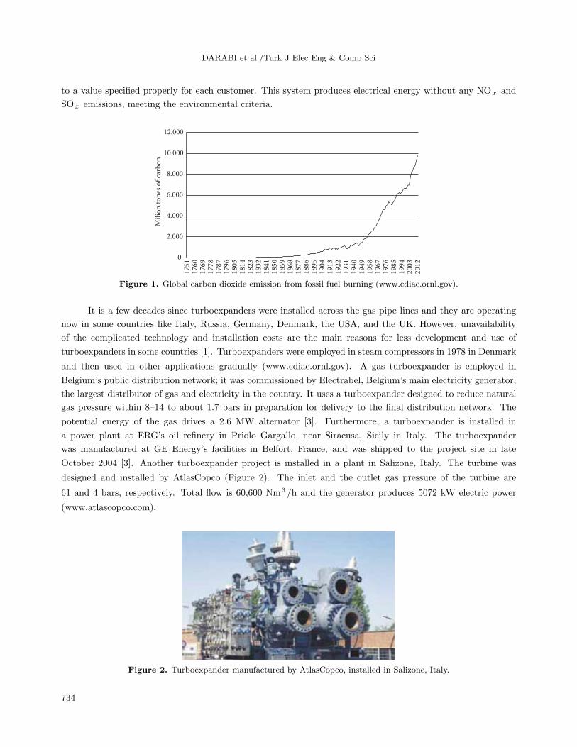
October 2004 [3]. Another turboexpander project is installed in a plant in Salizone, Italy. The turbine was
designed and installed by AtlasCopco (Figure 2). The inlet and the outlet gas pressure of the turbine are
61 and 4 bars, respectively. Total flow is 60,600 Nm3 /h and the generator produces 5072 kW electric power
(www.atlascopco.com).
Figure 2. Turboexpander manufactured by AtlasCopco, installed in Salizone, Italy.
734
DARABI et al./Turk J Elec Eng & Comp Sci
An analytic method for calculation of electric power generated by the pressure of the natural gas is
presented in [4]. It contains useful and practical points regarding the design of energy recovery systems based
on a turboexpander. The authors of [4] explained the required number of stages, the flow rate of the gas, and
the requirements of the preheater. They delivered some experimental results of a recovery system in [5]. The
system was operating in Ravenna (Italy) in 1987 and produced 971 MWh electric power during two individual
periods with the total length of 84 days.
The simulation results of a pressure reduction station of Czech Republic are reported in [6] in which the
preheating is done by use of the heat produced by the generator, gearbox, etc. This preheating system and the
influence of isentropic efficiency on the output power are studied in that paper.
In [7] a comparison between different combinations of TE-FC like a single turboexpander with a boiler, a
single turboexpander with a fuel cell system, and a dual turboexpander with a fuel cell system and an expansion
valve is presented. In other words, the income of the hybrid TE-FC system is studied using some cases.
A comprehensive thermodynamic analysis regarding energy and exergy calculations subject to varying
operating conditions is presented in [8]. Furthermore, a simplified and novel method is used in this paper for a
cost analysis to assess the amortization of the system.
Some papers like [9–12] investigate the performance of a gas turbine coupled with the fuel cell via heat
exchangers. The performance of such systems depends on the operating conditions. Therefore, the authors of
[9] present a parametric study to examine the effect of varying operating pressure, temperature, and current
density on the performance of the system. Improving of the efficiency by increasing steam to methane ratio
and pressure, and decreasing air feed rate is investigated in this paper. Although via the combination of fuel
cell and power plant as the bottoming cycle better performances and higher efficiencies can be obtained, the
pollution of the air as a result of burning of the gas is still a disadvantage. Therefore, simultaneous pressure
reduction and electrical energy production without any pollution make the hybrid TE-FC system a distinctive
and attractive alternative for energy extraction compared with other systems like the one indicated in [9].
The pressure reduction is accompanied by a temperature drop, which may cause a gas frizzing problem in
the low pressure side. Therefore, preheating of the gas is essential before passing through the expansion system.
It is done commonly by a gas-fired preheater while imposing fuel costs and CO2 emissions.
The hybrid system comprising a turboexpander and fuel cells is investigated in the current paper. In this
configuration both the turboexpander and the fuel cells produce electrical power while the fuel cell prepares
thermal energy for preheating the inlet gas of the turboexpander too.
The ratio of turboexpander and fuel cell investment costs has a significant impact on the tolerability
of the system from the economic point of view. There are many circumstances where the fuel cell utilization
along with a turboexpander does not suggest any considerable profits compared with an individually operated
turboexpander. A review of the literature reveals that although the hybrid TE-FC recapturing energy system
is investigated in some papers, the conditions in which the profit of the TE-FC combination is more than that
of an individually operated TE is not determined. Therefore, the conditions in which the use of the TE-FC
combination is justified need to be studied carefully. These conditions depend on the investment cost of the TE
and FC.The present paper proposes a methodology to specify the situation where the investment on the hybrid
TE-FC is reasonable regarding the target function defined properly. Using the proposed method, one can
understand when the application of FCs in conjunction with a TE is profitable. In this paper, the basic concept
of gas pressure energy is presented and the hybrid TE-FC system is considered from the economic point of view.
The investment strategy and the simulation results are presented and finally a conclusion is given.
735
DARABI et al./Turk J Elec Eng & Comp Sci
2. Gas energy extraction concept
The efficient transportation of natural gas from the production places to the end user locations is commonly
accomplished by extensive and complex pipeline networks [3]. Natural gas is compressed at a refinery in the
production place and then transported over long distances by pipelines. The pressure of the gas has to be
decreased again when delivering to the customers. In general, the pressure of the gas is reduced by wasting
energy devices, namely throttle valves through isenthalpic expansion. Recently, turboexpanders are suggested
and employed economically in some cases for the pressure reduction of large volume gas streams extracting
the electrical energy during the pressure conversion process. If the energy wasted by a conventional valve is
considerable, the pressure reduction valve can be replaced by a turboexpander getting the benefit of electrical
power too.
Many turboexpanders are designed to operate in the pressure within 130–200 bars. According to some
publications [1] and marketing web sites [13], turboexpanders are now available from 75 kW up to 130 MW.
Natural gas expansion through turboexpanders generates electric power with far greater efficiency than the
conventional thermal power utilities burning gas as fuel. In addition, turboexpanders do not create greenhouse
gases or significant environmental pollution [14].
For more reliability and safety of operation, the existing conventional pressure reduction valves are kept
and the expansion turbines are installed in parallel with them. In this condition, the redundant standby
regulator valve ensures continued safe operation in the event of turboexpander failure [15].
Most gases cool during expansion (Joule–Thompson effect) [3]. Nevertheless, temperature drop of the
gas is high in the case of employing turboexpanders; therefore, preheating of the gas is required to avoid
gas freezing at the outlet [6]. In some gas compositions, water or liquid hydrocarbons are produced at low
temperatures that yield hydrates, blockage of the pipeline, corrosion of the blades of the turbine, and failure
of the equipment. Therefore, it is essential to keep the outlet temperature above the hydrate formation range.
The Hammerschmidt correlation is used to predict the hydrate formation temperature as follows [16]:
T = 8.9P 0.285 (1)
The pressure reduction by the throttle valve and turboexpander is illustrated in Appendix A. As mentioned
earlier, preheating is the first stage of the pressure reduction process (points 1 and 2 of Appendix A). If the
flow of gas is given bym , the required power of the heat exchanger can be obtained by
Q = m (h2 − h1), (2)
where h1 and h2 are the gas enthalpies before and after preheating, respectively.
After preheating, high pressure gas passes through the turbine. Pressure reduction using a turboexpander
is an isentropic process that converts the released internal energy or enthalpy of the gas (points 2 and 3 of
Appendix A) to electric power via a generator coupled with the shaft of the turbine. The power delivered to
the turboexpander can be calculated using the equations as follows:
W = m (h3 − h2) (3)
Wact = ηturW , (4)
where h2 and h3 are the enthalpies of points 2 and 3 and, W is the power released by the gas, and Wact is
the output power of the turbine. The parameter ηtur is the efficiency of the turbine. Typical efficiency of the
turboexpanders is within 84% to 86% [13,17,18]. In this study, the value of ηtur is assumed to be 0.85.
736
DARABI et al./Turk J Elec Eng & Comp Sci
Given the temperature of the inlet gas, the temperature of the outlet gas of the turboexpander can be
evaluated by [19,20]:
T3 = T2
(P3
P2
)( k−1k )
, (5)
where P2 and P3 are the pressures of the inlet and outlet gas of the turboexpander, T2 and T3 are the
temperatures of the inlet and outlet gas of the turboexpander, and k is the isentropic constant.
Gas fired heaters or multipass water-bath or oil bath heat exchangers warm the gas passing through the
turboexpander [13]. The required heat can be gained from any nearby energy sources, preferably a gratis one
such as energy losses in the gearboxes, generators, gas engines, fuel cells, etc. [15]. Fuel cells generate electric
power, heat, and water from combination of hydrogen and oxygen with efficiency up to 85% of combined
heat/electricity. Fuel cells burn the natural gas and produce more electricity per unit of fuel while releasing less
carbon content pollution in comparison with combustion technology [3].
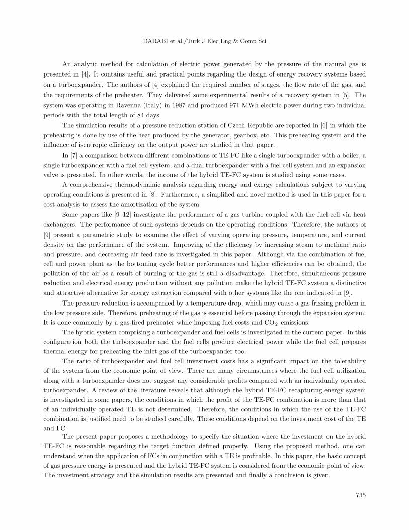
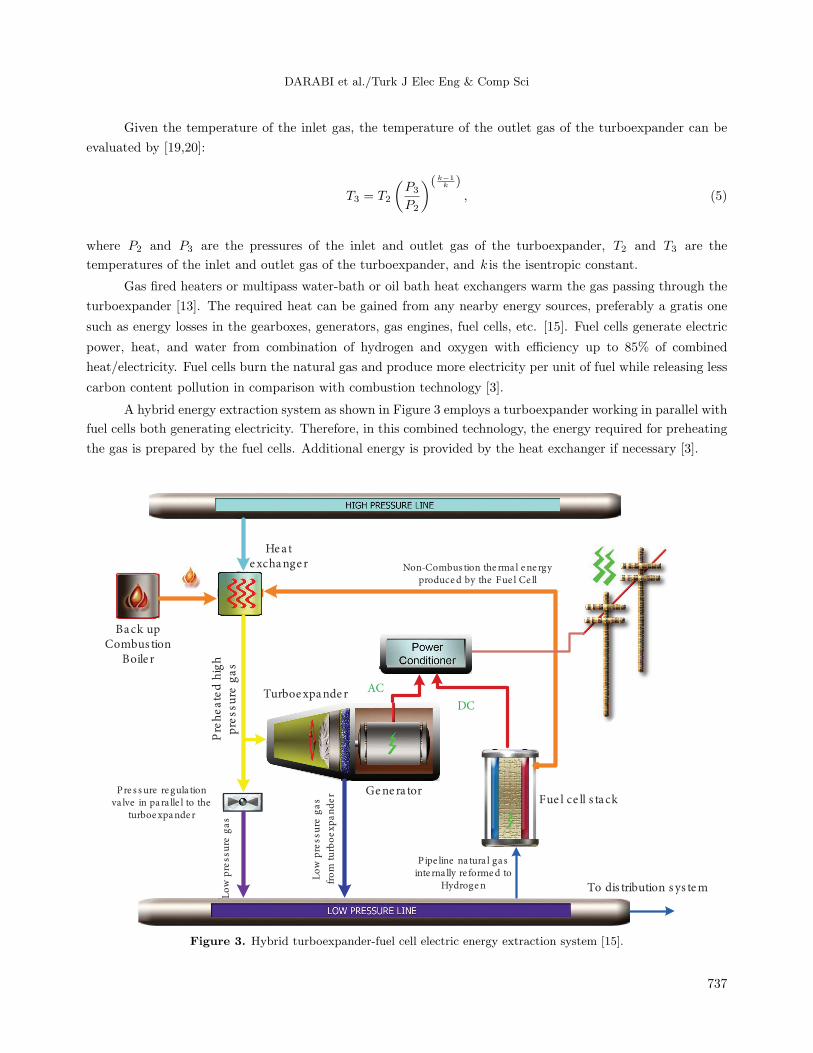
A hybrid energy extraction system as shown in Figure 3 employs a turboexpander working in parallel with
fuel cells both generating electricity. Therefore, in this combined technology, the energy required for preheating
the gas is prepared by the fuel cells. Additional energy is provided by the heat exchanger if necessary [3].
Back upCombus tion
Boile r
Hea texchange r
Turboexpande r
Pre s sure regula tionva lve in para lle l to the
turboexpande r
Lo
wp
ressu
reg
as
Fue l ce ll s tack
Pipe line na tura l gasinte rna lly re formed to
Hydrogen To dis tribution s ys tem
Pre
he
ate
dh
i gh
pr e
ssu
reg
as
Non-Combus tion the rma l ene rgyproduced by the Fue l Ce ll
AC
DC
Gene ra tor
Lo
wp
ressu
reg
as
fro
mtu
rbo
exp
an
de
r
Figure 3. Hybrid turboexpander-fuel cell electric energy extraction system [15].
737
DARABI et al./Turk J Elec Eng & Comp Sci
3. Economic assessment
For the economic assessment of the combined fuel cell-turboexpander application in gas pressure reduction
stations, investment cost and annual profit comprising the fuel, maintenance, and operation costs have to be
evaluated. For this purpose, in the first step the required thermal power is calculated using the temperature,
pressure, and flow of the inlet gas. The volume of consuming gas is determined according to the heating value
of the gas and then the energy extracted from the turboexpander is evaluated versus the pressures of the inlet
and the outlet gas and the efficiency of the turbine. Subsequently, the fuel consumption and the electrical and
thermal powers of the fuel cells are determined according to specifications available for the fuel cells.
3.1. Investment and annual profit
The initial investment cost of the project is the summation of the installation costs of the turboexpander
(TEInv), the fuel cells (FCInv), and the heat exchanger (ExcInv) written as
PR = TEInv + FCInv + ExcInv (6)
The annual profit is the difference between the income of the electric power and the operation costs, the
latter involving the fuel cost and the maintenance costs of the equipment. Therefore, the annual profit can be
calculated using the equations given as
PMT = TERev + FCRev − ExcFuel − FCFuel − TEOM − FCOM − ExcOM (7)
PMT = k1 ∗PTE + k1 ∗PFC − k2 ∗ (QTot− QFC) ∗CFuel −k1 ∗ PFC
efc−elec ∗HVfuel× CFuel
CElec−PTEMax ∗OMTE (8)
k1 = 8760 ∗ 3600 ∗ CElec (9)
k2 =8760 ∗ 3600
eExc ∗HVfuel(10)
QFC = α ∗ PFC (11)
The symbols used in the above equations are explained in the nomenclature. For further investigation let us
define variables X , Y and Z as below:
X =CFuel
CElec(12)
Y =PFC
PTE(13)
Z =CFC
CTE(14)
Applying the defined variables in Eqs. (12), (13), and (14), Eqs. (6) and (8) can be rewritten respectively as
PR = k15 + k11 ∗ Y ∗ Z − k13 ∗ Y (15)
PMT = k14 + k7 ∗ Y + k8 ∗X + k9 ∗ Y ∗X + k4 ∗ Y ∗ Z (16)
The coefficients used in Eqs. (15) and (16) are given in Table 1. In coefficient k4, γ is the O/M coefficient,
which indicates the operation and maintenance cost as a percent of investment cost. The transition from Eq.
(8) to Eq. (16) is presented in Appendix A.
738
DARABI et al./Turk J Elec Eng & Comp Sci
Table 1. List of variables.
TEP/TEMaxP*TEOM13k =
TETE CP4k =
TEP*3k5k =
TotMaxQ*ExcOM6k =
)ExcOM*1k(*TEP7k +=
TotMaxQ*2k*ElecC8k =
))fuelHV*elecfce(1kElecC**2k(*TEP9k =
TEC*TEMaxP10k =
TEC*TEP11k =
ExcC*TotMaxQ12k =
ExcC**TEP13k =
6k5k14k +=
12k10k15k +=
The fuel cell is a clean energy producer with no greenhouse gases. However, the fuel cells may be
considered costly; thus the necessity of economic assessment is inevitable. Two economic criteria are addressed
in the next section for economic assessment.
4. Economic criteria calculation
Variation in the currency influences the economic evaluations. Particularly in some countries due to sanctions
and political and economic instabilities, variation in the national currency versus international ones is substan-
tial. For considering this matter properly, a discounting rate as an alternative of currency variation is employed
for the profit evaluation. In fact, discounting rate is a parameter that indicates the profit of the same money if
it were invested in other projects instead.
Internal rate of return (IRR) is the discounting rate at which the costs of the project are equal to its
profits. Therefore, IRR is the real profit of the project obtained by solving the nonlinear equation of
−PR+ PMT ((1 + r)n − 1
r × (1 + r)n) = 0 (17)
Payback period (PP) is one of the most important criteria in the economic evaluation. PP is a period in which
the profit of the project covers the capital investment costs. Therefore, PP can be calculated as
PP =Log( PMT
PMT−r×PR )
Log(1 + r)(18)
Installation of fuel cells with a turboexpander will be reasonable if any increment in the capacity of the fuel
cells improves the economic criteria, e.g. decreases the payback period or increases the internal rate of return.
It means the rates of variations of PP and IRR versus capacity increment of fuel cells are negative and positive,
respectively. Obviously the reasonable boundaries of the fuel cells investment correspond to the conditions in
which the variation of the aforementioned criteria with respect to capacity of the fuel cells becomes zero.
739
DARABI et al./Turk J Elec Eng & Comp Sci
To clarify the procedure, let us consider a pressure reduction station in which the flow, temperature, and
pressure of the inlet gas are as given in Table 2.
The pressure and temperature of the output gas are regulated at 250 psi and 10 ◦C, respectively. Using
these data, the enthalpies of the input and output gas of this station are determined and given in Table 2.
In order to calculate the thermal power required to preheat the gas, at first the temperature of the inlet gas
of the turboexpander (as given in Table 2) is determined using Eq. (5). The enthalpy of the inlet gas of the
turboexpander is then determined. Finally, using the flow of the gas and the difference between the enthalpies
of the inlet and outlet gas of the exchanger, the required total thermal power as given in Table 3 is calculated
by Eq. (2).
Table 2. Data of pressure reduction station.
h3(kJ/kg) T3(°C) P3 (psi) h2 (kJ/kg) T2 (o C) P2( psi) h1
(kJ/kg) T1 (°C) P1(psi)
Flow
(kg/s)
Flow
(m3/s) Month
–50 10 250 145.6 103 780 –76.5 16 780 138.9 3.47 Jan
–50 10 250 129 94.6 720 –75 15 720 128.1 3.49 Feb
–50 10 250 145.4 102.2 770 –75.2 16 770 155.2 3.26 March
–50 10 250 161 108 855 –70.2 21 855 126.9 2.93 April
–50 10 250 174.5 115 920 –80 19 920 135.5 2.85 May
–50 10 250 185.5 119 985 –86.6 18.5 985 140.5 2.74 June
–50 10 250 200.2 126 1030 –85.8 20 1030 158.8 2.97 July
–50 10 250 209 130 1090 –86.5 21 1090 160.5 2.84 Aug
–50 10 250 216.1 132.3 1140 –79.7 23 1140 179.1 3.05 Sep
–50 10 250 181.64 118.5 980 –90.5 19 980 160.0 3.14 Oct
–50 10 250 169.7 112.7 905 –89.8 17 905 152.3 3.24 Nov
–50 10 250 154 107 830 –80.8 16 830 145.8 3.40 Dec
Table 3. Required thermal power calculation.
. . Q(1012J) Q(Mw) Δh1-2 (kJ/kg) Avg. "ow (kg/s) Month
80.0 45.4 222.1 138.9 Jan
67.8 47.4 204.0 128.1 Feb
88.7 53.0 220.7 155.2 March
78.6 43.6 231.2 126.9 April
92.3 39.5 254.5 135.5 May
102.4 34.2 272.1 140.5 June
121.7 30.8 286.0 158.8 July
127.0 26.1 295.5 160.5 Aug
141.9 34.2 295.8 179.1 Sep
112.9 29.3 272.1 160.0 Oct
102.5 34.5 259.5 152.3 Nov
88.7 38.2 234.8 145.8 Dec
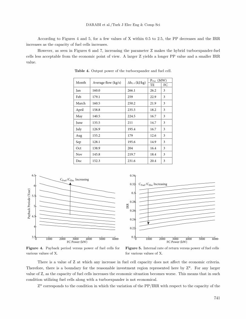
Table 4 shows the monthly electrical power produced by the turboexpander. Knowing that, the investment
cost and the annual profit are calculated applying Eqs. (15) and (16) and then the IRR and PP are obtained
using Eqs. (17) and (18). Considering the peripheral losses, the efficiency of the heat exchanger is assumed to
be 70% in this calculation. Moreover, the heating value of the gas is assumed to be 37200 kJ/m3 . Figures 4
to 7 show the PP and the IRR of the TE-FC combination studied in this paper versus capacity of the fuel cells
for various values of X and Z.
740
DARABI et al./Turk J Elec Eng & Comp Sci
According to Figures 4 and 5, for a few values of X within 0.5 to 2.5, the PP decreases and the IRR
increases as the capacity of fuel cells increases.
However, as seen in Figures 6 and 7, increasing the parameter Z makes the hybrid turboexpander-fuel
cells less acceptable from the economic point of view. A larger Z yields a longer PP value and a smaller IRR
value.
Table 4. Output power of the turboexpander and fuel cell.
Month Average !ow (kg/s) Δh2-3 (kJ/kg)POut (MW)
TE FC
Jan 160.0 266.1 26.2 3
Feb 179.1 259 22.9 3
March 160.5 250.2 21.9 3
April 158.8 235.5 18.2 3
May 140.5 224.5 16.7 3
June 135.5 211 14.7 3
July 126.9 195.4 16.7 3
Aug 155.2 179 12.6 3
Sep 128.1 195.6 14.9 3
Oct 138.9 204 16.4 3
Nov 145.8 219.7 18.4 3
Dec 152.3 231.6 20.4 3
0 1000 2000 3000 4000 5000 60003.5
4
4.5
5
5.5
6
6.5
FC Power (kW)
Pay
bac
k P
erio
de
(Yea
r)
CFuel /CElec Increasing
0 1000 2000 3000 4000 5000 60000.2
0.22
0.24
0.26
0.28
0.3
0.32
0.34
FC Power (kW)
IRR
CFuel /CElec Increasing
Figure 4. Payback period versus power of fuel cells for
various values of X.
Figure 5. Internal rate of return versus power of fuel cells
for various values of X.
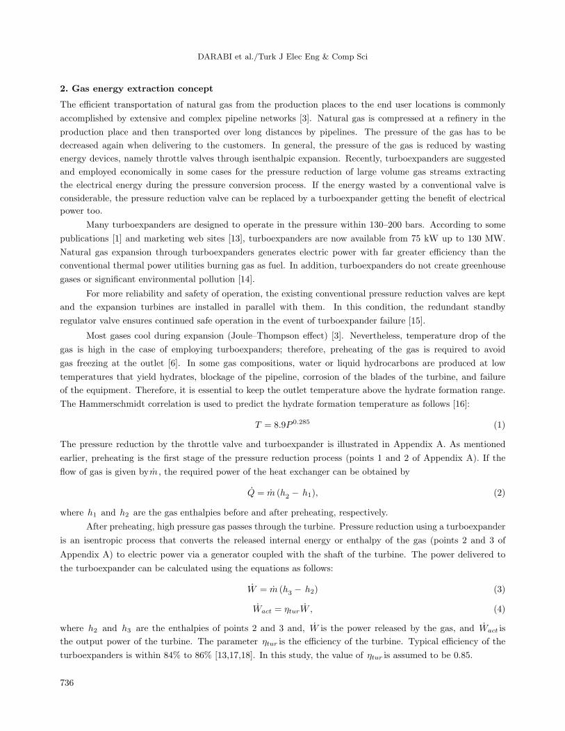
There is a value of Z at which any increase in fuel cell capacity does not affect the economic criteria.
Therefore, there is a boundary for the reasonable investment region represented here by Z*. For any larger
value of Z, as the capacity of fuel cells increases the economic situation becomes worse. This means that in such
condition utilizing fuel cells along with a turboexpander is not economical.
Z* corresponds to the condition in which the variation of the PP/IRR with respect to the capacity of the
741
DARABI et al./Turk J Elec Eng & Comp Sci
fuel cells is zero, i.e.
∂PP
∂PFC=
∂(
Log( PMTPMT−r×PR )
Log(1+r)
)∂PFC
= 0
∂(Log( PMT
PMT−r×PR ))
∂PFC= 0
∂PMT
∂PFC×(PMT − r × PR)− ∂(PMT − r × PR)
∂PFC×PMT = −∂PMT
∂PFC×r×PR+
∂(r × PR)
∂PFC×PMT = 0 (19)
A× (k7 + k9×X) + Z × (k4×A+D × (k14 + k8×X)) − C × (k8×X + k14) = 0 (20)
0 1000 2000 3000 4000 5000 60003.6
3.7
3.8
3.9
4
4.1
4.2
4.3
4.4
4.5
4.6
FC Power (kW)
Pay
bac
k P
erio
d (
Yea
r)
CFC/CTE=1.5
CFC /CTE=1
CFC /CTE =2
0 1000 2000 3000 4000 5000 60000.27
0.28
0.29
0.3
0.31
0.32
0.33
0.34
FC Power (kW)
IRR CFC /CTE =1.5
CFC
/CTE
=1
CFC /CTE =2
Figure 6. Payback period versus power of the fuel cells
for various values of Z.
Figure 7. Internal rate of return versus power of the fuel
cells for various values of Z.
Therefore, the value of Z* becomes
Z∗ =C × (k8×X + k14)−A× (k7 + k9×X)
(k4×A+D × (k14 + k8×X))(21)
The variables of Eqs. (19) to (21) were defined earlier in Table 1. The transition from Eq. (19) to Eq. (20) is
presented in Appendix A. As seen in Eq. (21) and illustrated by Figure 8, the value of Z∗ depends on the value
of X. This figure shows the situation where the investment in the hybrid TE-FC plant is reasonable regarding
the economic point of view. Using Figure 8, one can decide whether to utilize the hybrid turboexpander-fuel
cells or an individual turboexpander regarding the economic aspects such as fuel and electrical energy prices.
In other words, for a given fuel to electrical energy price, the hybrid FC-TE system is reasonable if the FC to
TE investment cost is lower than the critical value indicated in Figure 8.
742
DARABI et al./Turk J Elec Eng & Comp Sci
0 0.5 1 1.5 2 2.51.3
1.4
1.5
1.6
1.7
1.8
1.9
2
2.1
2.2
2.3
Fuel to electrical energy price
Cri
tica
l F
C t
o T
E i
nve
stm
ent
cost
(Z
*)
Figure 8. Critical value of Z (Z∗) versus X.
5. Conclusion
For the purpose of extracting electrical energy from gas flow, this paper presented a detailed investigation for
replacing the existing pressure reduction valves by hybrid plants comprising turboexpanders and fuel cells. A
procedure for economic assessment was developed and the results were given. The results indicate that from
the economic point of view, utilization of fuel cells may be undeserved in some conditions. These depend on
the turboexpander and fuel cell investment costs, fuel cost, and electrical energy price. Any increase in the fuel
cells to turboexpander investment costs ratio makes the hybrid system less acceptable. A critical value for the
fuel cells to the turboexpander investment cost ratio was obtained indicating the boundary of the profitable
fuel cell application. It is shown that for a value larger than the critical value, utilization of fuel cells along
with a turboexpander will not be economically acceptable. Considering the daily increasing advances in fuel
cells technology, the authors think that the method proposed in this paper can be applied to evaluate the
reasonability of hybrid TE-FC utilization with some confidence.
Nomenclature
T Temperature (◦F)P Pressure (psi)
W Power
Wact Output power of the turbine delivered tothe generator
m Flow of gash Enthalpy of gas
Q Thermal powerηtur Efficiency of the turbinek Isentropic constantsTE TurboexpanderFC Fuel cellTEInv Total investment cost of turboexpanderFCInv Total investment cost of fuel cellExcInv Total investment cost of exchangerCFC Fuel cell investment cost per kW ($/kW)
CTE Turboexpander investment cost per kW($/kW)
PR Investment costPMT Annual profitTERev Annual revenue of the turboexpanderFCRev Annual revenue of the fuel cellsExcFuel Annual fuel cost of the heat exchangerFCFuel Annual fuel cost of the fuel cellTEOM Annual operation and maintenance cost of
the turboexpanderFCOM Annual operation and maintenance cost of
the fuel cellExcOM Annual operation and maintenance cost of
the exchangerPTE Average output power of the turboexpanderPFC Average output power of the fuel cell
QTot Required total thermal power
743
DARABI et al./Turk J Elec Eng & Comp Sci
QFC Thermal output power of the fuel cellsCFuel Fuel cost ($/m3)efc−elec Electrical efficiency of the fuel cellsHVfuel Heating value of the fuel (BTU/m3)CElec Electrical energy price ($/kWh)PTEMax Maximum output power of the turboexpan-
der
QTotMaxRequired maximum thermal power
α Thermal to electrical power ratio of the fuelcells
eExc Efficiency of the heat exchangerγ O/M coefficientr Discounting raten Life time of the hybrid systemPP Payback periodIRR Internal rate of return
Acknowledgments
The authors would like to thank the Iranian National Science Foundation (INSF) for the financial support and
the Research Centre of Marine Propulsions, Shahrood University of Technology, Iran, where the project was
conducted.
References
[1] Bloch H, Soares C. Turboexpanders and Process Applications. 1st ed. USA: Gulf Professional Publishing, 2001.
[2] Taheri Seresht R, Khodaei Jalalabadi H, Rashidian B. Retrofit of Tehran City Gate Station (C.G.S.No.2) by Using
Turboexpander. In: Thirty-second Industrial Energy Technology Conference; 19–22 May 2010; New Orleans, LA,
USA: pp. 22-28.
[3] Daneshi H, Khorashadi Zadeh H, Lotfjou Choobari A. Turboexpander as a distributed generator. In: IEEE Power
and Energy Society General Meeting; 20–24 July 2008; Pittsburgh, PA, USA: IEEE. pp. 1-7.
[4] Mirandola A, Minca L. Energy recovery by expansion of high pressure natural gas. In: 21st Intersociety Energy
Conversion Engineering Conference; 25–29 Augest 1986; San Diego, CA, USA: pp. 16-21.
[5] Mirandola A, Macor A. Experimental analysis of an energy recovery plant by expansion of natural gas. In: 23rd
Intersociety Energy Conversion Engineering Conference; 31 July–5 August 1988; Denver, CO, USA: pp. 33-38.
[6] Pozivil J. Use of expansion turbines in natural gas pressure reduction stations. Acta Montan Slovaca 2004; 9:
258-260.
[7] Howard C, Oosthuizen P, Peppley B. An investigation of the performance of a hybrid turboexpander-fuel cell system
for power recovery at natural gas pressure reduction stations. Appl Therm Eng 2011; 31: 2165-2170.
[8] Rashidi R, Berg P, Dincer I. Performance investigation of a combined MCFC system. Int J Hydrogen Energ 2009;
34: 4395-4405.
[9] Rashidi R, Dincer I, Berg P. Energy and exergy analyses of a hybrid MCFC system. J Power Sources 2008; 185:
1107-1114.
[10] Simon G, Parodi F, Fermeglia M, Taccani R. Simulation of process for electrical energy production based on molten
carbonate fuel cells. J Power Sources 2003; 115: 210-218.
[11] Gemmen R, Liese E, Rivera J, Brouwer J. Development of dynamic modeling tools for solid oxide and molten
carbonate hybrid fuel cell gas turbine systems. In: ASME/IGTI Turbo Expo; 15–19 June 2000; Munich, Germany:
pp. 25-34.
[12] Gnann M. The MTU fuel cell hot module cogeneration unit 250 kW. In: 7th Grove Fuel Cell Symposium; 11–13
September 2001; London, UK: pp. 23-28.
[13] Bloch H. Consider turbo expanders. Hydrocarb Process 2001; 80: 1-7.
[14] Mansoor S, Mansoor A. Power generation opportunities in Bangladesh from gas pressure reducing stations. In: 3rd
International Conference on Electrical & Computer Engineering; 28–30 December 2004; Dhaka, Bangladesh: pp.
36-42.
744
DARABI et al./Turk J Elec Eng & Comp Sci
[15] Howard CR. Hybrid turboexpander and fuel cell system for power recovery at natural gas pressure reduction
stations. MSc, Queen’s University Kingston, Ontario, Canada, 2009.
[16] Fattah KAA. Evaluation of empirical correlations for natural gas hydrate predictions. Oil and Gas Business Journal
2004; 2: 1-12.
[17] Maddaloni J, Rowe A. Natural gas exergy recovery powering distributed hydrogen production. Int J Hydrogen
Energ 2007; 32: 557-566.
[18] Bloch H. Become familiar with turbo expander applications. Hydrocarb Process 2001; 80: 8–17.
[19] Rahman M. Power generation from pressure reduction in the natural gas supply chain in Bangladesh. J Mech Eng
2010; 41: 89-95.
[20] Krahenbuhl D, Zwyssig C, Weser H, Kolar J. Experimental results of a mesoscale electric power generation system
from pressurized gas flow. J Micromech Microeng 2009; 19: 1-6.
745
DARABI et al./Turk J Elec Eng & Comp Sci
A. Appendix
Figure A.1 shows the gas pressure reduction by the pressure reduction valve (PRV).
Figure A.1. Gas pressure reduction by PRV.
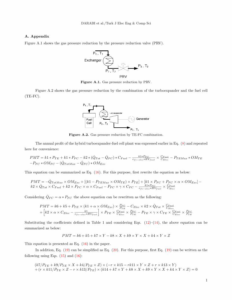
Figure A.2 shows the gas pressure reduction by the combination of the turboexpander and the fuel cell
(TE-FC).
Figure A.2. Gas pressure reduction by TE-FC combination.
The annual profit of the hybrid turboexpander-fuel cell plant was expressed earlier in Eq. (8) and repeated
here for convenience:
PMT = k1 ∗ PTE + k1 ∗ PFC − k2 ∗ (QTot − QFC) ∗ CFuel − k1∗PFC
efc−elec∗HVfuel× CFuel
CElec− PTEMax ∗OMTE
−PFC ∗OMFC − (QTotMax − QFC) ∗OMExc
This equation can be summarized as Eq. (16). For this purpose, first rewrite the equation as below:
PMT = −QTotMax ×OMExc + [(k1− PTEMax ×OMTE)× PTE ] + [k1× PFC + PFC × α×OMExc]−k2× QTot × CFuel + k2× PFC × α× CFuel − PFC × γ × CFC − k1∗PFC
efc−elec∗HVfuel× CFuel
CElec
Considering QFC = α ∗ PFC the above equation can be rewritten as the following:
PMT = k6 + k5 + PTE × (k1 + α×OMExc)× PFC
PTE− CElec × k2× QTot × CFuel
CElec
+[k2× α× CElec − k1
efc−elec∗HVfuel
]× PTE × CFuel
CElec× PFC
PTE− PTE × γ × CTE × CFuel
CElec× PFC
PTE
Substituting the coefficients defined in Table 1 and considering Eqs. (12)–(14), the above equation can be
summarized as below:
PMT = k6 + k5 + k7× Y − k8×X + k9× Y ×X + k4× Y × Z
This equation is presented as Eq. (16) in the paper.
In addition, Eq. (19) can be simplified as Eq. (20). For this purpose, first Eq. (19) can be written as the
following using Eqs. (15) and (16):
(k7/PTE + k9/PTE ×X + k4/PTE × Z)× (−r × k15− rk11× Y × Z + r × k13× Y )+ (r × k11/PTE × Z − r × k13/PTE)× (k14 + k7× Y + k8×X + k9× Y ×X + k4× Y × Z) = 0
1
DARABI et al./Turk J Elec Eng & Comp Sci
Multiplication of the terms can extend the above equation as:
−k7× r × k15/PTE − k9×X × r × k15/PTE − k4× Z × r × k15/PTE − k7× r × k11× Y × Z/PTE
−k9×X × r × k11× Y × Z/PTE − k4× Z × r × k11× Y × Z/PTE + k7× k13× r × Y/PTE
+k9×X × k13× r × Y/PTE + k4× Z × k13× r × Y/PTE + r × k11× Z × k14/PTE + k7×Y × r × k11× Z/PTE + k8×X × r × k11× Z/PTE + k9× Y ×X × r × k11× Z/PTE
+k4× Y × Z × r × k11× Z/PTE − r × k13× k14/PTE − k7× Y × r × k13/PTE − k8×X×r × k13/PTE − k9× Y ×X × r × k13/PTE − k4× Y × Z × r × k13/PTE = 0
The above equation can be simplified as below:
−k7× r × k15/PTE − k9×X × r × k15/PTE − k4× Z × r × k15/PTE + r × k11× Z × k14/PTE
+k8×X × r × k11× Z/PTE − r × k13× k14/PTE − k8×X × r × k13/PTE = 0
Define some symbols as below:
A = −r × k15/PTE
B = r × k14/PTE
C = r × k13/PTE
D = r × k11/PTE
Finally, with substituting of A, B, C, and D, Eq. (19) can be expressed as below:
A× (k7 + k9×X) + Z × (k4×A+D × (k14 + k8×X)) − C × (k8×X + k14) = 0
This equation is presented as Eq. (20) in the paper.
2