turbocharger design analysis solutions - ansys assets/auto...turbocharger design & analysis...
TRANSCRIPT

Turbocharger Design & Analysis Solutions
Bill HolmesBrad Hutchinson
Detroit, October 2012

Agenda
• ANSYS overview• ANSYS TurboSystem• Blade row solutions
– The ANSYS Transformation methods
• An example: turbocharger compressor analysis
• Summary

ANSYS Vision for Rotating Machinery:• Full machine simulation
– High fidelity simulation of all components
– Simulate complex phenomena and processes• Unsteady combustion, compressor stall, cavitation, noise, fracture, component interactions, advanced materials.....
– Integrated tool set for all geometry and physics
– Large scale High Performance Computing (HPC) enabled

ANSYS TurboSystem

Turbomachinery @ ANSYS
• Axial and centrifugal compressors
• Axial and radial turbines (Steam & gas)
• Centrifugal, mixed‐flow and axial pumps
• Axial and radial fans• Automotive turbomachinery
• Water turbines• Wind turbines

ANSYS TurboSystem• Complete turbomachinery design and analysis in ANSYS Workbench– Geometry– Throughflow– Meshing– CFD– Thermal– Combustion– Structural mechanics– Rotordynamics– Post‐processing– Optimization
This presentation will focus on ANSYS blade row fluid dynamics for turbocharger compressors

ANSYS WorkbenchParametric Geometry (Meanline & Through-Flow)
Mesh AnalysisRobust Design

ANSYS Workbench

ANSYS Workbench

ANSYS Workbench
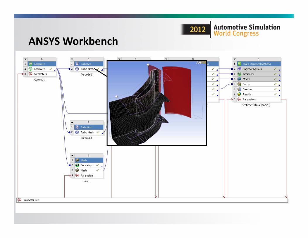
ANSYS Workbench

ANSYS Workbench

ANSYS Workbench

ANSYS Workbench
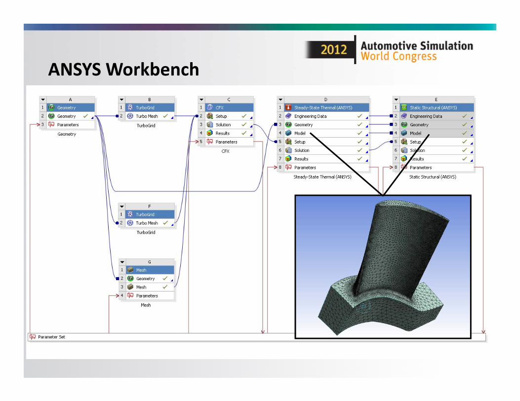
ANSYS Workbench

ANSYS Workbench

ANSYS Workbench

BladeModeler ‐Meanline Design
• Vista CCD– Centrifugal compressor rotor design
• Real gas capability

BladeModeler – Meanline Design
• Vista RTD– Radial turbine preliminary design

ANSYS BladeModeler
• Design comparison• Visible in meridionalsketches, angle/thickness views, blade‐to‐blade view and 3D view

ANSYS TurboGrid
• Automated grid generation for bladed turbomachinery components
• High quality hexahedral grids
• Repeatable– Minimize mesh
influence in design comparison
• Scalable– Maintain quality with
mesh refinement

Centrifugal Compressor

ANSYS CFD @ Turbomachinery
• Fast & scalable solver• Low speed to supersonic• Steady/transient• Turbo‐specific BC’s
• Turbulence & heat transfer• Multiple Frame of Reference• Multi‐phase flow• Real fluids• Fluid/structure interaction• …

SST Model
Laminar‐turbulent transition Streamline
curvature & rotation
'Automatic' wall
functions
Stagnation line flows
EARSM
Wall roughness
Scale‐Adaptive Simulation
Detached Eddy
Simulation
Turbulence Model

ANSYS Design Exploration
• Sensitivity analysis• Design optimization• Robustness evaluation
initial

Mechanical• Mechanical deformation
– Rotational forces– Surface pressure loads
• Thermal stress– Temperature, Heat flux,
…• Modal analysis
– Frequencies• Blade flutter
– Aerodynamic damping• Forced response
– Transient Rotor‐Stator– Full 2‐way FSI

ANSYS Transient Blade Row Methods

TBR with pitch change: The ANSYS Transformation methods
– Problem: How to obtain the full‐wheel transient solution, but at low cost?
• Solution: The ANSYS TBR Transformation family of methodsoNew models minimize number of simulated passages, providing enormous efficiency gains and reduced infrastructure requirements

Transientwith Pitch Change
Transientwith Pitch Change
Steadywith Pitch Change
TransientFull-Domain
TransientFull-Domain
Profile Transformation
Profile Transformation
Time Transformation
Time Transformation
Fourier Transformation
Fourier Transformation
Time Domain Status:Release & Beta
HarmonicTransformation
HarmonicTransformation
Frequency Domain
Fast Blade Row Solutions
Status:Development

ANSYS TBR Applications
Turbine
Gust pitch
Blade Passage pitchGust speed
Gust AnalysisGust Analysis
Turbine
Gust pitch
Blade Passage pitchGust speed
Gust AnalysisBlade FlutterBlade Flutter
PeriodPeriod
displacemen
tdisplacemen
tIBPAIBPA
Damping
Coe
f.Da
mping
Coe
f.
Blade Flutter
Period
displacemen
t
102 Nbjj
NbIBPA
IBPADa
mping
Coe
f.
TBR Applications
Multi‐StageMulti‐StageMulti‐StageSingle‐Stage

Trends @ Turbocharging
• Unsteady‐State– Rotor‐Stator Interaction
(Off‐Design)– Inlet distortion– Acoustics
• Turbulent flow with conjugate heat transfer
• Multi‐physics– Forced response– Thermal
• Optimization & Robust Design
• Map Width Enhancement, mixed flow turbine wheels, volute configuration
ETH Zurich

Multi Physics Modeling
3D CAD
CSM Mesh CFD Mesh
Static & Thermal CSM Aerodynamic CFD
Load Transfer

ANSYS Workbench
ANSYS Turbo System
Geometry Mesh Analysis
CA
D
Throughflow Robust Design

Example Application: Turbocharger Compressor

Turbocharger Compressor Analysis: A Best Practice Example
• Methodology• Preliminary Design• Geometry & Meshing• Impeller‐only analysis• Impeller‐diffuser‐volute analysis
• Post‐processing and interpretation

Methodology
• Pre‐CFD– Start with geometry that meets design specifications
• From Vista CCD, CCM, TF and BladeModeler• Impeller‐only analysis
– The impeller is the heart of the compression system ‐‐‐understand it first
– Overall performance: how good can it be, can it be better?– Nature of the flow, strengths and weaknesses– What factors affect performance? Predictions?
• Whole system– Impeller‐diffuser‐volute analysis– Volute‐only analysis ‐‐‐ useful?
• Post‐processing– Quantitative and qualitative

Geometry
• 1‐D design developed in VISTA CCD– Based on prescribed duty, design constraints
• Impeller Geometry– VISTA CCD, CCM BladeModeler VISTA TF– Make adjustments according to package constraints, design rules,
approach etc.• Meridional path• Blade profile/thickness• Hub/backface• Tip clearance
• Volute Geometry– Spreadsheet based design
• Mass + angular momentum conservation approach (free vortex)• Drives a parameterized DesignModeler geometry

Compressor Design Requirements
Parameter Value
Diameter 48 [mm]
Number of Vanes 6 + 6
Inlet Temperature 288 [K]
Inlet Pressure 101.35 [kPa]
Mass Flow Rate 0.12 [kg/s]
Pressure Ratio 2.15
Tip Speed 391 [m/s]
Shaft Speed 155,733 [rev min^‐1]
• High Specific Flow impeller with vaneless diffuser of radius ratio 1.7
• Typical for a gasoline engine with capacity of 1.6L.
• Mid map operating point

Initial Sizing
• Vista CCD used to create a geometry from design requirements

Vista CCD: Output
• Iterate in CCD to achieve acceptable preliminary design

Vista CCM: Input
• Vista CCM used to create a preliminary compressor map

Vista CCM: Output
• Turbocharger compressor is typically operating at off design

Initial Geometry Creation
• VISTA TF requires a geometry: from BladeModeler– Push‐button solution from Vista CCD
Compressor Shroud Section

Initial Geometry Creation
Compressor Hub Section
Vista TF: 2D Analysis
• Vista TF is a throughflow (streamline curvature) solver– Used to provide further insight into design– Contour plots show circumferentially averaged
quantities– 2D Charts show various design parameters such as
loading, incidence and deviation• Based on results, geometry can be quickly modified and analyzed again– Blade and flowpath design improved– Can be parametric and optimization can be
performed

Vista TF: Qualitative OutputTangential velocity Solution
error
Meridionalvelocity
Static pressure

Vista TF

Final Impeller Design
• Final impeller geometry steps prior to meshing– Direct to TurboGrid for hex– Create fluid flow path for tet meshing
• Volute geometry is generated to match impeller– Details later

Final GeometriesImpeller and vaneless diffuser Volute
Meshing
• Impeller Mesh– Use a hexahedral mesh: TurboGrid ATM – Pay attention to:
• Target mesh size• Balance• Boundary layer resolution• Y+• Tip clearance• Aspect ratio
• Volute mesh• ANSYS meshing
– Tets + prisms for boundary layer resolution– Local mesh refinement near tongue– Match diffuser outlet/volute inlet spanwise mesh distribution

Impeller‐only Analysis
• Impeller + part of vaneless diffuser– How much of the vaneless space to model?
• Grid refinement study– Grid: The biggest factor affecting predictions– Tetrahedral Elements Vs. Hexahedral Elements– Understand the effect of grid size on prediction
• Target: “working grid” size with Y+=2• Ideally, double/half the grid size in each direction
– 1/8X, 1X, 8X working grid size• Estimate of grid independent‐solution
– Effect of fillets– Look at key points on the map
• Nominal design, near surge line, near choke, choke

Example: Mesh Independence Study
• Impeller + Vaneless Diffuser Analyzed at 155, 733 rpm• Three operating points
– Design Flow Rate– Near Choke– Near Stall/Surge
• Compared Hex mesh vs. Tet mesh

Mesh Summary
# of Nodes
Blade Y+
Meshing Tool
Meshing Method
Meshing Time
MeshFile Size
Max VolRatio
Max Length Ratio
0.142m 8 TurboGrid ATM 1 min 3.67MB 159 2132
1.12m 4 TurboGrid ATM 1 min 34.8MB 88 4308
8.58m 2 TurboGrid ATM 3 min 273MB 34 3547
# of Nodes
Blade Y+
Meshing Tool
Meshing Method
Meshing Time
MeshFile Size
MinAngle
MinQuality
0.143m 8 ICEM CFD Octree ~5 min 56.7MB 0.65 0.01
1.08m 4 ICEM CFD Octree ~30 min 601MB 0.31 0.0029
7.50m 2 ICEM CFD Octree ~1.5 hr 4.4GB 0.23 1.3e‐06
Hexahedral
Tetrahedral

Hex Coarse Mesh

Hex Medium Mesh

Hex Fine Mesh

Tet Coarse Mesh

Tet Medium Mesh

Tet Fine Mesh

Mesh Independence: Hex vs. TetTotal Pressure
Tet mesh at approximately 8 million nodes still is not as accurate as Hex mesh at 125 thousand nodes!

Mesh Independence: Hex vs. TetIsentropic Efficiency

Mesh Sensitivity: Hex speedline

Mesh Sensitivity: Fine Tet speedline added
Tet mesh at approximately 8 million nodes still is not as accurate as Hex mesh at 125 thousand nodes!

Effect of Fillet
• 1.5 mm fillet included at main and splitter blade root – compared to blade geometry without fillet

Fillet Study: Effect on Pressure Ratio
Difference only apparent at/near choke
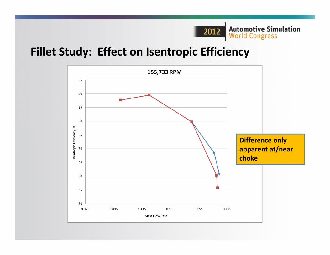
Fillet Study: Effect on Isentropic Efficiency
Difference only apparent at/near choke
Assembly Analysis
• How much do I really need to model, and using what methods?– Impeller‐diffuser‐volute?– Volute only (including part of vaneless diffuser)?
• Inlet specified from exit of impeller‐only analysis– Steady state, transient?
• We did the following, for comparison purposes:– “Frozen rotor” ‐‐‐ full 360 degrees– “Stage” analysis ‐‐‐ one impeller with full volute– Transient Rotor Stator ‐‐‐ full 360 degrees– Volute only
• Constant Pt, Tt, flow direction• As above but with a spanwise profile

Volute Mesh• Relatively Coarse Mesh used for Study
• Size: 370,000 nodes– Tet Elements = 1.1
million– Prism Elements = 0.32
million• Quality Statistics
– Average Element Quality = 0.71
– Min Element Quality = 0.046

Effects of Diffuser and Volute
• Comparison of three different configurations– Impeller Only (Single Passage)– Impeller + Vaneless Diffuser (Single Passage)– Impeller + Vaneless Diffuser + Volute (Full 360, frozen rotor)
• Compare speedlines– 155,733 rpm– Pt ratio = (Pt outlet/Pt inlet)– Isentropic Efficiency

Pressure ratio predictions

Isentropic efficiency predictions

Impeller Behavior
• Now look at impeller only performance in two configurations– Impeller‐only simulation– Impeller‐diffuser‐volute simulation
• Speedlines shows Impeller behaves similarly regardless of downstream geometry– Pt ratio = (Pt impeller outlet/Pt impeller inlet)– Isentropic Efficiency for impeller only
• Significant value in examining individual components to gain insight

Impeller pressure ratio predictions for two configurations

Isentropic efficiency predictions for two configurations

Effect of rotating‐stationary frame interface type
• Comparison of three interface types between diffuser and volute– Stage (single passage impeller/diffuser, full volute)– Frozen rotor (full 360 degrees)– Transient Rotor Stator
• For all cases– Impeller + vaneless diffuser modeled in rotating frame
– Volute modeled in stationary frame

Effect of interface type on total pressure prediction
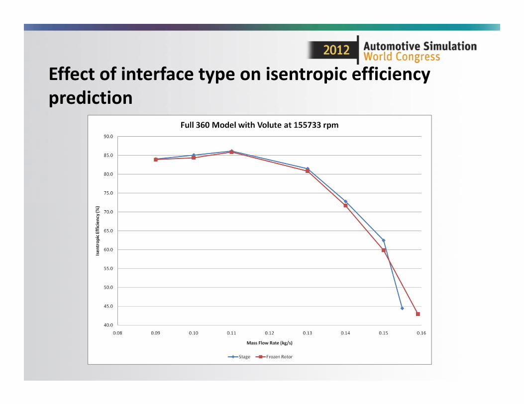
Effect of interface type on isentropic efficiency prediction

Post Processing
• Before starting:– Make sure solutions are converged!
• Run with a big enough time step!• Quantitative
– Impeller• Pt, Tt, Abs. flow angle, isentropic efficiency• Distortion factor• Blade loading
– Volute: recovery factor, loss coefficient– Estimate grid‐independent solution
• Qualitative– Blade‐to‐blade and meridional averaged– Unrolled plot at exit of impeller

CFD Results
• Examine results from Compressor Report in CFD Post

CFD Results
• Or use table generation tool in CFD Post to extract custom information at various streamwise locations
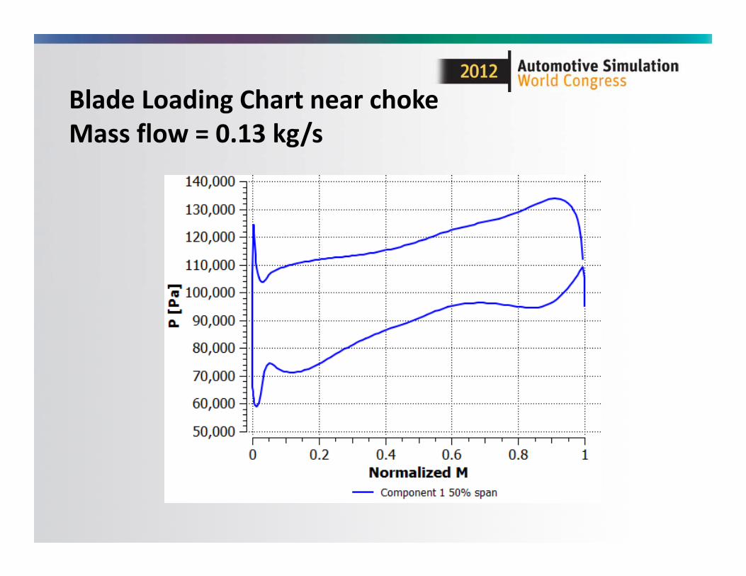
Blade Loading Chart near chokeMass flow = 0.13 kg/s

Relative Mach Number near chokeMass flow = 0.13 kg/s

Relative Velocity near chokeMass flow = 0.13 kg/s

Meridional velocity near chokeMass Flow = 0.13 kg/s

Static pressure near chokeMass flow = 0.13 kg/s

Relative Mach Number near chokeMass flow = 0.13 kg/s
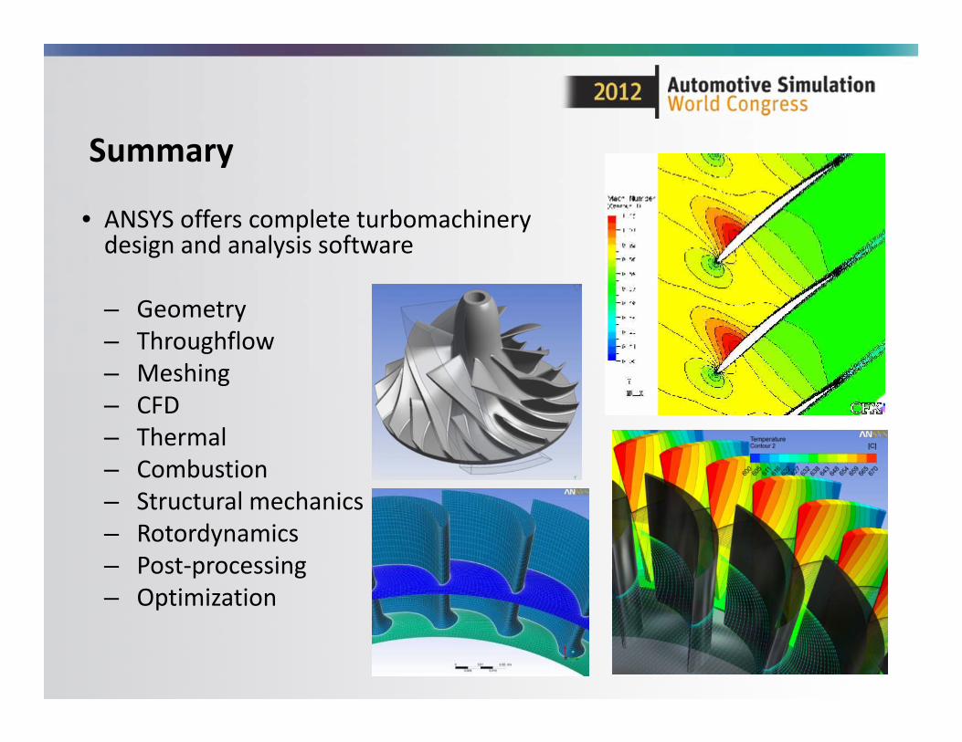
Summary
• ANSYS offers complete turbomachinery design and analysis software
– Geometry– Throughflow– Meshing– CFD– Thermal– Combustion– Structural mechanics– Rotordynamics– Post‐processing– Optimization